investigation of flow in elbow pipe using lattice...
TRANSCRIPT

NIK MUQAFFI BIN NIK JAFFAR NOV 2009
INVESTIGATION OF FLOW IN ELBOW PIPE USING LATTICE BOLTZMANN METHOD
NIK MUQAFFI BIN NIK JAFFAR
Report submitted in fulfilment of the requirements
for the award of the degree of
Bachelor of Mechanical Engineering
Faculty of Mechanical Engineering
UNIVERSITI MALAYSIA PAHANG
NOVEMBER 2009

NIK MUQAFFI BIN NIK JAFFAR NOV 2009
SUPERVISOR’S DECLARATION
I hereby declare that I have checked this project and in my opinion, this project is adequate
in terms of scope and quality for the award of the degree of Bachelor of Mechanical.
Signature :
Name of Supervisor : MR. MUHAMAD ZUHAIRI SULAIMAN
Position :
Date :

NIK MUQAFFI BIN NIK JAFFAR NOV 2009
STUDENT’S DECLARATION
I hereby declare that the work in this project is my own except for quotations and
summaries which have been duly acknowledged. The project has not been accepted for any
degree and is not concurrently submitted for award of other degree.
Signature :
Name : NIK MUQAFFI BIN NIK JAFFAR
I.D Number : MA06087
Date :

NIK MUQAFFI BIN NIK JAFFAR NOV 2009
Dedicated to my parents and my siblings

NIK MUQAFFI BIN NIK JAFFAR NOV 2009
ACKNOWLEDGEMENT
Grateful and thanks to Allah SWT for making it possible for me to complete this project on time. I am also like to express my sincere gratitude to my supervisor Mr Muhamad Zuhairi Sulaiman for his germinal ideas, invaluable guidance, continuous encouragement and constant support in making this research possible. I appreciate his consistent support from the first day I applied to graduate program to these concluding moments. I sincerely thanks for the time spent proofreading and correcting my many mistakes.
My thanks also go to all members of the staff of the Mechanical Engineering
Department, UMP, who helped me in many ways and made my stay at UMP pleasant and unforgettable.
I acknowledge my sincere indebtedness and gratitude to my parents and siblings for their love, dream and sacrifice throughout my life. I cannot find the appropriate words that could properly describe my appreciation for their devotion, support and faith in my ability to attain my goals.

NIK MUQAFFI BIN NIK JAFFAR NOV 2009
ABSTRACT
The investigation is about the flow in elbow pipe with the different Reynold numbers and geometry mesh. There are three types of elbow pipe geometry in this case study which known as elbow pipe with expansion ratio 1.0, 1.5 and 2.0. All types of elbow pipe that has been applied with laminar flow that Reynold number 100, 150, 200 and 250. The simulation of the model was studied under isothermal lattice Boltzmann method condition in which we investigated computationally in a two-dimensional configuration using a fluid dynamics program. The different Reynold numbers and expansion ratio has given the different flow pattern around the elbow pipe region. The minimum Reynold numbers has been increased after the flow pattern in elbow pipe was simulate and elbow pipe with expansion ratio 2.0 has given the maximum reattachment length of the circulation that occur in elbow pipe. Finally, for future investigation the correlations obtained from this numerical result could be used to investigate the flow in the elbow pipe.

NIK MUQAFFI BIN NIK JAFFAR NOV 2009
ABSTRAK
Kajian mengenai aliran didalam paip bersiku telah dibuat dengan nombor Reynold dan bentuk paip bersiku yang berbeza. Tiga rekabentuk paip bersiku yang di kaji yang dikenali paip bersiku dengan nisbah pembesaran 1.0, 1.5 dan 2.0. Ketiga-tiga paip bersiku ini telah di aplikasikan dengan aliran seragam iaitu nombor Reynold 100, 150, 200 dan 250. Simulasi model dikaji dengan kaedah isothermal lattice boltzmann menggunakan program dinamik bendalir dua dimensi. Nombor Reynold dan bentuk paip bersiku yang berbeza memberi bentuk aliran yang berbeza disekitar paip bersiku. Nombor reynold minimum telah di pertingkatkan selepas bentuk aliran disimulasikan dan paip bersiku nisbah pembesaran 2.0 memberi pusaran yang paling maksimum didalam paip bersiku. Kajian dan analisis parameter atau faktor lain yang mempengaruhi aliran didalam paip bersiku perlu diambil kira untuk kajian masa akan datang.

NIK MUQAFFI BIN NIK JAFFAR NOV 2009
TABLE OF CONTENTS
Page
SUPERVISOR’S DECLARATION ii STUDENT’S DECLARATION iii ACKNOWLEDGEMENTS v ABSTRACT vi ABSTRAK vii TABLE OF CONTENTS viii LIST OF FIGURES x LIST OF TABLES xi LIST OF SYMBOLS xii LIST OF ABBREVIATIONS xiv
CHAPTER 1 INTRODUCTION
1.1 Introduction 1
1.2 Objective 2
1.3 Scope 3
1.4 Problem statement 3
CHAPTER 2 LITERATURE REVIEW
2.1 Elbow Pipe 4
2.2 Computational Fluid dynamics (CFD) 4
2.3 Molecular Dynamics 6
2.4 Lattice gas approach 7
2.5 Lattice Boltzmann method (LBM) 8
2.6 Numerical of Lattice Boltzmann method 9
2.7 Boltzmann Collision function 11
2.8 Bhatnagar-Gross-Krook (BGK) Collision Model 13

NIK MUQAFFI BIN NIK JAFFAR NOV 2009
2.9 Single Relaxation Time Bhatnagar-Gross-Krook 14
2.10 Viscosity 15
2.11 Boundary Conditions 15
2.12 Backward-Facing Step 16
CHAPTER 3 METHODOLOGY
3.1 Description of numerical method 18
3.2 Boundary condition 20
3.3 Simulation Algorithm 23
CHAPTER 4 RESULT AND DISCUSSION
4.1 Simulation of flow pattern in elbow pipe 24
4.2 Comparison flow pattern with different expansion ratio 32
4.3 Discussion 33
CHAPTER 5 CONCLUSION
5.1 Conclusion 34
5.2 Recommendation 36
REFERENCES 37
APPENDIXS
A Programming language 39
B Simulation of flow in elbow pipe 46

NIK MUQAFFI BIN NIK JAFFAR NOV 2009
LIST OF FIGURES
Figure No. Title Page
2.1 D2Q9 x,y velocity component 14
2.2 Collisions of FHP LGA model 15
3.1 Sketch of elbow pipe geometry 20
3.2 Expansion ratio, H/h 21
3.3 Bounce back boundary 22
3.4 Simulation algorithm 23
4.1 Flow pattern in the elbow pipe. Expansion ratio H/h = 1.0; ( a ) Re = 100; ( b ) Re = 150; ( c ) Re = 200; ( d ) Re = 250
25
4.2 Vortex length / inlet height vs. Reynolds numbers for expansion ratio, H/h = 1.0
26
4.3 Flow pattern in the elbow pipe. Expansion ratio H/h = 1.5; ( a ) Re = 100; ( b ) Re = 150; ( c ) Re = 200; ( d ) Re = 250
28
4.4 Vortex length / inlet height vs. Reynolds numbers for expansion ratio, H/h = 1.5
29
4.5 Flow pattern in the elbow pipe. Expansion ratio H/h = 2.0; ( a ) Re = 100; ( b ) Re = 150; ( c ) Re = 200; ( d ) Re = 250
30
4.6 Vortex length / inlet height vs. Reynolds numbers for expansion ratio, H/h = 2.0.
31
4.7 Comparison of vortex length / inlet height vs. Reynolds numbers for expansion ratio, H/h = 1.0, 1.5 and 2.0
32

NIK MUQAFFI BIN NIK JAFFAR NOV 2009
LIST OF TABLES
Table No. Title Page
4.1 Comparison of vortex length / inlet height vs. Reynolds numbers for different expansion ratio of elbow pipe
32
NIK MUQAFFI BIN NIK JAFFAR NOV 2009
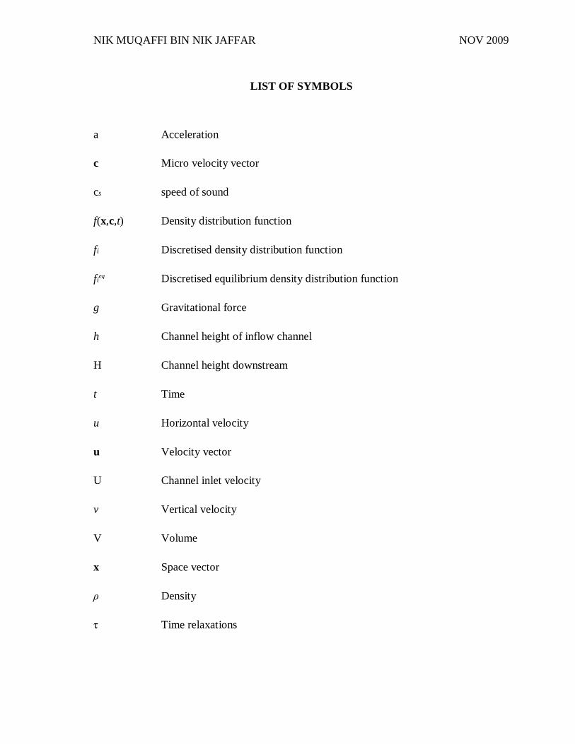
LIST OF SYMBOLS
a Acceleration
c Micro velocity vector
cs speed of sound
f(x,c,t) Density distribution function
fi Discretised density distribution function
fieq Discretised equilibrium density distribution function
g Gravitational force
h Channel height of inflow channel
H Channel height downstream
t Time
u Horizontal velocity
u Velocity vector
U Channel inlet velocity
v Vertical velocity
V Volume
x Space vector
ρ Density
τ Time relaxations

NIK MUQAFFI BIN NIK JAFFAR NOV 2009
LIST OF ABBREVIATIONS
BGK Bhatnagar Gross Krook
CFD Computational fluid dynamic
D2Q9 Two dimensional nine velocities model
LB Lattice Boltzmann
LBE Lattice Boltzmann equation
LBM Lattice Boltzmann method
LGA Lattice gas approach
MD Molecular dynamic
2-D Two dimensional
Non-dimensional parameters
Re Reynold number

NIK MUQAFFI BIN NIK JAFFAR NOV 2009
CHAPTER 1
INTRODUCTION
In recent years the lattice Boltzmann equation (LBE) method has been developed as
an alternative numerical approach in computational fluid dynamics (CFD). Originated from
the discrete kinetic theory, the lattice Boltzmann equation method has emerged with the
promise to become a superior modeling platform, both computationally and conceptually,
compared to the existing arsenal of the continuum-based computational fluid dynamics
methods. The lattice Boltzmann equation method has been applied for simulation of various
kinds of fluid flows under different conditions. The number of papers on the lattice
Boltzmann equation method and its applications continues to grow rapidly, especially in the
direction of complex and multiphase media. The focus is placed on the fundamental
principles of the lattice Boltzmann equation approach. Special attention is paid to
advantages and limitations of the method, and its perspectives to be a useful framework for
description of complex flows and interfacial (and multiphase) phenomena. The
computational performance of the lattice Boltzmann equation method is examined,
comparing it to other computational fluid dynamics methods, which directly solve for the
transport equations of the macroscopic variables.
By study lattice Boltzmann equation method approach in computational fluid
dynamics, we can study fluid mechanics that concerned with understanding, predicting, and
controlling the behavior of a fluid. Since we live in a dense gas atmosphere on a planet
NIK MUQAFFI BIN NIK JAFFAR NOV 2009
mostly covered by liquid, a rudimentary grasp of fluid mechanics is part of everyday life.
For an engineer, fluid mechanics is an important field of the applied sciences with many
practical and exciting applications. The field of fluid mechanics has historically been
divided into two branches, fluid statics and fluid dynamics. Fluid statics, or hydrostatics, is
concerned with the behavior of a fluid at rest or nearly so. Fluid dynamics involves the
study of a fluid in motion.
Piping, which uses fluid to transport particles through a pipeline, has been used
commercially for many years in a wide range of applications. Nevertheless, the details of
the flow behavior of the particles and fluid continue to be of interest to engineers concerned
with design of piping systems. Elbows, which provide piping systems with considerable
flexibility by allowing routing and distributing, are one of the key parameters affecting the
fluid flow structure. Centrifugal forces in the elbow cause the fluid and solid particles to
segregate, with the solid particles impinging on the outer wall of the elbow and forming a
relatively dense phase structure. Most of the particles are piped within a small portion of
the pipe cross-section just after the elbow. In addition, the particles are decelerated in the
elbow due to particle–wall and particle–particle interactions and, thus, an acceleration
region is required in the pipe downstream of the elbow to reaccelerate the particles to the
piping fluid velocity. In the case of horizontal-to-horizontal elbows, formation of deposits
near the elbow exit and concluded the particle deposit was created traveling along the
bottom of the pipe, was slowed by frictional forces to a velocity of zero. In this project will
concern with fluid dynamics that investigates the fluid flow in elbow pipe by using lattice
Boltzmann equation method.
1.1 OBJECTIVES
1. To study isothermal lattice Boltzmann method.
2. To simulate fluid flow in the elbow pipe geometry.
3. To investigate fluid flow behavior in the elbow pipe.

NIK MUQAFFI BIN NIK JAFFAR NOV 2009
1.2 SCOPES
Scope of this project is study Lattice Boltzmann method within isothermal flow.
Lattice Boltzmann method programming language will be applied in FORTRAN software.
Simulation of fluid flow in elbow pipe will be considered to study the flow pattern in elbow
pipe.
1.3 PROBLEM STATEMENT
An analytical solution of the governing equations of fluid dynamics is usually not
possible. Complex engineering geometries and a natural tendency for fluid flows to become
unstable ensure that analytical solutions will remain elusive. Computational methods
include finite difference, finite element, finite volume, and other computational approaches
in which digital computers are used to supply numerical solutions of approximate versions
of the governing equations. Lattice Boltzmann method is still under development process
by various researchers. Lattice Boltzmann method has vast advantages for example in
channel flow. In this study, investigation on fluid flow behavior will be carried out by using
lattice Boltzmann method.
NIK MUQAFFI BIN NIK JAFFAR NOV 2009
CHAPTER 2
LITERATURE REVIEW
2.1 ELBOW PIPE
A pipe fitting installed between two lengths of pipe or tube allowing a change of
direction, usually 90° or 45°. The ends may be machined for butt welding or threaded.
When the two ends differ in size, it is called a reducing or reducer elbow. Most of the
elbows are available in short radius or long radius of types. The short radius elbows have a
center to end distance equal. A tee is used to either combine or split a fluid flow. Most
common are tees with the same inlet and outlet sizes, but 'reducing' tees are available as
well. Tee-fittings are also an integral part of the computer-enthusiast level water cooling
solutions found in many modern enthusiast PCs. The fitting is one of the three main
components of a T-Line, alongside an end-cap or fill port and a length of tubing. They are
plumbed into the system, with the perpendicular barb and its attached stretch of tubing
leading to a fill port or a cap.
2.2 COMPUTATIONAL FLUID DYNAMICS (CFD)
Nowadays, computational methods such as computational fluid dynamics (CFD)
has become an essential tool in solving the Navier-Stokes Equation, the continuity
equation, the energy equation and the equation derived from them. Incompressible Navier-

NIK MUQAFFI BIN NIK JAFFAR NOV 2009
Stokes equation is the heart of the CFD, which represent a local conservation law for the
momentum in the system. This equation only partially addresses the complexity of most
fluids of interest in engineering applications; it is successfully applied in different areas for
predictions of fluid flows.
The classical approach in CFD, treat of such fluids and describe the new physical
properties in terms of transport phenomena are related to a new observable, macroscopic
property. A PDE is written down for the dynamics of this property then is solved by an
appropriate numerical technique. In a fluid with important temperature variations for
example, a new observable property, the temperature, is introduced and its dynamics is
described by a heat transport equation.
The setting up of a numerical simulation begins with creating a computational grid.
The flow variables are calculated at the node points of this grid and, in some methods, at
some intermediate points as well. The spacing between grid points has to be fine enough to
attain a high enough degree of accuracy. The are advantages, however, to keep the number
of grid points small since more grids points means more computer memory is required and
a greater time is needed to perform each iteration of the calculation. The simplest
computational grid is a rectangular lattice with fixed spacing between node points in each
dimension. There are a range of methods that use unstructured grids where the density of
the node points is not constant and is higher in the regions where more accuracy is required.
Unstructured meshes often end up being connected in a triangular or tetrahedral fashion
because these shapes fill space well and they require a minimum number of vertices. Some
methods even use adaptive meshes where node points are created and destroyed as flow
features move through the computational domain. This keeps the total number of nodes to a
minimum, while still providing the required resolution for certain flow features.

NIK MUQAFFI BIN NIK JAFFAR NOV 2009
Figure 2.1: D2Q9 x,y velocity component
Source: M C. Sukop, et.al, 2003
2.3 MOLECULAR DYNAMICS
One obviously way to simulate a fluid flow on a computer is to model the individual
molecules which make up the fluid which so called the molecular dynamics (MD)
approach. MD approach is based on Newton’s second law or the equation of motion, F =
ma. From the knowledge of the force on each atom, it is possible to determine the
acceleration of each atom in the system. Integration of the equations of the motion then
yields a trajectory that describes the positions, velocities and accelerations of the particles
as they vary with time. The method is deterministic; once the position and velocities of
each atom are known, the state of the system can be predicted at any time in the future or
the past. However, this can be restrictively time consuming when considering even a very
small volume of fluid. Even when a gas is being considered where there are fewer

NIK MUQAFFI BIN NIK JAFFAR NOV 2009
molecules and a larger time step can be used, because of the longer mean free path of the
molecules, the number of molecules that can be considered is severely limited.
2.4 LATTICE GAS APPROACH
The LGA model Frisch et al. and Wolfram proposed evolves on a 2D triangular
lattice space. The particles have momentum which allows them to move from one site on
the lattice to another in discrete time steps. On a particular lattice site, there is either no
particle or one particle with a particular momentum pointing to a nearest neighbor site.
Therefore, there are at most six particles at one site simultaneously; hence this model is
called the 6-bit model or FHP model. The evolution of the LGA model consists of two
steps: collision and advection. The collision process is partially described in Fig. 3.For
example; two particles colliding with opposite momentum will rotate their momentum 60o
clockwise or counter-clockwise with equal probability.
Figure 2.2: Collisions of FHP LGA model.
Source: M C. Sukop, et.al, 2003
NIK MUQAFFI BIN NIK JAFFAR NOV 2009
The configurations can be easily obtained by rotational transformation, and which
are invariant under the collision process. It should be noticed that the particle number, the
momentum, and the energy are conserved in the collision process locally and exactly
because the FHP model has only one speed, the energy is no longer an independent
variable: it is equivalent to the particle number. However, for multi-speed models, the
energy is an independent variable.
To summarize, LGA are inherently simple; their discrete nature makes them straight
forward to implement by computer and they lend themselves to agent based approaches
which reflect the intrinsic individuality of cells. Local rules can be developed from a
microscopic level phenomenon understanding which is direct and intuitive. LGA provide
an opportunity to study interactions and behavior which are difficult to formulate as
continuum equations.
2.5 LATTICE BOLTZMANN METHOD (LBM)
Furthermore, Lattice Boltzmann method has the ease and accuracy with which it
enables complicated boundary geometries to be processed, hence, investigating suitable
boundary conditions for lattice Boltzmann simulations has become a highly researched area
in many engineering and scientific applications. Another advantage of using LBM is the
simplicity of programming, the parallelism of the algorithm, and the capability of
incorporating complex microscopic interactions. It is an approach that bridges microscopic
phenomena with the continuum macroscopic equations.
In particular, this method is promising for simulations of fluid flow involving
complex interfacial dynamics. It is a discrete computational method based upon the
Boltzmann equation. It considers a typical volume element of fluid to be composed of a
collection of particles that are represented by a particle velocity distribution function for
each fluid component at each grid point. It obtains macroscopic flow information based on
integration of probability density function.

NIK MUQAFFI BIN NIK JAFFAR NOV 2009
Recently, research on LBM was focus on two-dimensional simulation. Hui et.al
2007 extended to study the dumbbell moving in a pressure-driven Poiseuille flow in two
dimensions and choose to work on a two-dimensional square lattice with nine velocities.
Two dimensional channel flows with different Reynolds number is tested using lattice
Boltzmann method under different pressure and velocity boundary condition. (Ying et.al,
2005).
The LBM has a number of advantages over other conventional CFD methods. The
algorithm is simple and can be implemented with a kernel of just a few hundred lines. The
algorithm can also be easily modified to allow for the application of other, more complex
simulation components. For example the LBM can be extended to describe the evolution of
binary fluid, or extended to allow for more complex boundary conditions. Thus the LBM is
an ideal tool in fluid simulation.
2.6 NUMARICAL OF LATTICE BOLTZMANN METHOD
In the Lattice-Boltzmann method, space is divided into a regular lattice and real
numbers at each lattice site represent the single-particle distribution function at that site,
which is equal to the expected number of identical particles in each of the available particle
states i. In the simplest model, each particle state i is defined by a particle velocity, which is
limited to a discrete set of allowed velocities. During each discrete time step of the
simulation, particles move, or hop, to the nearest lattice site along their direction of motion,
where they “collide” with other particles that arrive at the same site. The outcome of the
collision is determined by solving the kinetic Boltzmann equation for the new particle-
distribution function at that site and the particle distribution function is updated.
The outcome of collisions is very simply approximated by assuming that the
moment a of the interacting particles will be redistributed at some constant rate toward an
equilibrium distribution . This simplification is called the single-time-relaxation
approximation. In mathematical terms, the time evolution of the single-particle distribution
is given by
eqif

NIK MUQAFFI BIN NIK JAFFAR NOV 2009
(2.1)
where is the density distribution function along the і direction at lattice site x, ∆t the
time step and cі is the particle velocity in the і direction. The second term on the right-hand
side is the simplified collision operator Ωi. The rate of change toward equilibrium is 1/τ, the
inverse of the relaxation time, and is chosen to produce the desired value of the fluid
viscosity. The equilibrium function can be written as
2
/ 2 exp22
eqi D
nfR TR T
c v
(2.2)
The macroscopic density n and velocity vector u are calculated by the conservation laws,
(2.3)
For single phase flow, pressure can be calculated from 2sp c n with the speed of sound
1 3sc .
To obtain the Navier-Stokes equations, the equilibrium distribution functional form must be
carefully chosen. In the 9-speed square lattice, a suitable equilibrium distribution function
has been proposed with Maxwell-Boltzmann equilibrium distribution function
(2.4)
(2.5)
In the limit of long wavelengths, the LBE recovers the following quasi-incompressible
NSEs by the Chapman–Enskog expansion
eqif
eqif
361,9
1,94
9~65~21
22
23
2931 uucuc iii
eqif
ii
i ii
n f
n f
u c
tftftftttf eqiiiii ,,1,, xxxcx

NIK MUQAFFI BIN NIK JAFFAR NOV 2009
20
1 0s
p utc
(2.6)
2
0
1u u u p ut
(2.7)
Where ρ0 is the constant average density in the system and the kinematics viscosity is
2 16
(2.8)
If, in addition, a low Mach number assumption is invoked as the nearly incompressible
limit is approached, equations will approximate the incompressible Navier-
Stokes equations with error of the order of M². Here, the primed quantities denote
fluctuations. It should be pointed out that using the artificial compressibility to simulate
incompressible Navier-Stokes equations has been proposed by Chorin and others. One of
the main differences between the lattice Boltzmann method and previous artificial-
compressible methods is that a different set of primitive variables is used in each approach.
In addition, all terms in LBM, including convection terms and dissipation terms, are solved
through relaxation to equilibrium (via the collision operator),whereas in the artificial-
compressible methods, some explicit finite difference schemes must be employed for these
terms.
2.7 BOLTZMANN COLLISION FUNCTION
Any solution of the Boltzmann equation, requires that an expression for the
collision operator Ω(ƒ). If the collision is to conserve mass, momentum and energy, it is
required that
∫ 1풄푐
Ω(ƒ)푑푥 (2.9)
Collision can change the distribution function ƒ(x,c,t) in two ways;
0).( u
t