investigation of footing settlements adjacent to circular ... · direction of the tunnel by an...
TRANSCRIPT

Investigation of Footing Settlements Adjacent to
Circular Tunnels
Ahmed Elzoghby Elsaied Assistant Professor, Construction Research Institute
Cairo, Egypt
Abstract-Urbanization developments with limited available area
for construction, have led transportation to go underground
areas. Unexpected damages due to wrong predictions for the
tunnel lining behavior, the surrounding soil, and footing
settlements on/or adjacent to the tunnel emphasized the
importance of the current study. A 2-D finite element model
using Plaxis V 8.6 program was developed to simulate the tunnel
system performance based on Cairo, Egypt, metro tunnel-Line 3
measurements as a case study. An elasto-plastic constitutive
model was adopted to represent the soil behavior surrounding
the tunnel. Studying the rate of a footing settlement within the
vicinity of tunnel was therefore of great importance. The effects
were expressed in terms of surface displacement and soil stress
change caused by tunneling. The horizontal and the vertical
distances between the tunnel and the footing subjected to
various loads, and the diameter of the tunnel at different depths
were carefully considered. Also, rotation of the footing adjacent
to tunnel was taken into account. Results indicated that the
volume loss in soil due to tunneling is an important parameter in
soil-tunnel numerical models to predict the ground settlements.
The influence of the tunnel becomes negligible on the adjacent
footing settlements beyond a horizontal distance of about 2.5
times the tunnel diameter or a vertical depth equal to twice the
footing width. Correlation was achieved between measured and
numerical results and predictions have been made on probable
advance values to occur in the future.
Keywords- Tunnel, Soil, Footing settlements, Numerical model
I. INTRODUCTION
A shield tunnel is constructed by excavating the soil at the
front of the Tunnel Boring Machine (TBM) and installing a
tunnel lining behind it. In this procedure the soil is generally
over-excavated, which means that the cross section area
occupied by the final tunnel lining is always less than the
excavated soil area. As a result of the tunnel construction
process, measures are taken to fill up this gap to avoid
damage to the existing structure above the tunnel. However,
there are no enough studies to develop a method that can
accurately predict of ground deformations according to the
tunneling effects on the surroundings. Most problems are
related to damage of the surrounding buildings due to surface
and subsurface ground subsidence [1 - 3]. Finite element
method as an analytical technique to solve tunneling
geotechnical problems were used [4 - 7]. An appropriate
model to predict the behavior of the tunnel in Tehran No. 3
subway line was carried out [8]. They determined the
variation of radial displacements along the longitudinal
direction of the tunnel by an empirical method. Also, the
tunnel deformations were defined. The ground movement
properties caused by shield tunneling and expanding
construction were numerically discussed [9]. Wang et al. [10]
used finite element analysis to predict surface settlement
above tunnel in clayey soil. The influence of drainage
condition on surface settlement was also investigated.
In the present study, a finite element model was used to
model the greater Cairo metro-Line-3 tunnel system
performance as a case study. The Greater Cairo metro tunnel-
Line 3 was constructed in 2011. A numerical analysis of the
interaction between adjacent strip footing and circular
tunneling was carried out. Various simulations were done
using a finite element technique which takes into
consideration the presence of the footing during tunneling.
The numerous models for adjacent footing and the tunnel are
assumed and the results are estimated and analyzed.
Numerical analysis was conducted using a commercial finite
element program PLAXIS V8, 6 [11] to examine
configurations which have not been measured
experimentally. The study explained the direct effect of the
variation of the tunnel diameter and the horizontal and
vertical distance between the tunnel and the footing on the
footing settlement behavior. The constitutive model for this
analysis utilizes elasto-plastic materials. The hardening soil
models were employed for soil and a linear constitutive
model was representing the tunnel liner. Model boundaries
and volume losses (VL) were discussed to elaborate the
performance of the metro tunnel. The associated stress
changes in soil were studied and presented based on the
tunnel construction process. The results obtained are
compared with those obtained by the field measurement to
verify the accuracy of the finite element model.
II. CASE STUDY PARAMETERS
The analyzed metro tunnel area lies within the Nile valley in
Cairo vicinity. The soil layers and their parameters required
to model the performance of the tunnel were indicated in
Figure 1. The distinct soil layers encountered through the
case study was analyzed by the author based on the National
Authority for Tunnels report (after NAT, 2009) [12]. Duncan
and Chang [13] material model was used to simulate soil as it
assumes a hyperbolic stress-strain relation.
373
International Journal of Engineering Research & Technology (IJERT)
IJERT
IJERT
ISSN: 2278-0181
www.ijert.orgIJERTV3IS100298
(This work is licensed under a Creative Commons Attribution 4.0 International License.)
Vol. 3 Issue 10, October- 2014

Where: Ʋ = Poisson’s ratio, γb =Bulk density, E=Modulus of Elasticity, ɸ=Angle of internal friction of soil,
C=Cohesion of soil, Rf =Failure ratio, m= Power for stress-level dependency of stiffness, degree) =Angle of dilatancy
Figure 1 Cross section of soil layer including their parameters along the Greater Cairo metro-line 3 tunnel.
III. NUMERICAL ANALYSIS
The FEM can be particularly useful for identifying the
patterns of deformations and stress distribution in the soil, at
all various loading stages. A plane strain elasto-plastic finite
element analysis was carried out. The boundary conditions
were chosen such that the right and the left vertical boundary
were constrained horizontally. The bottom horizontal
boundary was constrained in both the horizontal and vertical
directions. The finite element model (FEM) takes into
account the effects of the vertical overburden pressure, the
lateral earth pressure, the non-linear properties of the soil,
and the linear properties of the tunnel. Moreover, the
interface between the soil media and the tunnel liner was
considered in the numerical model. The soil was modeled
using hardening soil model, which is elasto-plastic hyperbolic
model. This model has the following basic characteristics: a-
stress dependent stiffness according to a power law, b-
hyperbolic relationship between strain and deviatoric stress,
c- distinction between primary deviatoric loading and
unloading/reloading, d- failure behavior according to the
Mohr-Coulomb model, and e-an elasto-plastic Duncan-Chang
model. The hardening soil model parameters that used in the
finite element calculation were derived from a series of a
laboratory tests carried by the National Authority for
Tunnels.
A tunnel lining consists of curved beams. The lining
properties can be specified in the material for beams.
Similarly, a tunnel interface is modeled as a curved interface.
The contraction parameter was used to simulate the volume
loss in the soil due to the tunnel construction. This procedure
Fill
Medium dense
Sand
Medium dense
sand
Silty clay
Dense sand
ν = 0.30, γb = 17 KN/m3, E = 4000 KN/m
2, ɸ = 27
o,
C = 0 KN/m2, R f =0.9,
o, m=0.6
ν = 0.30, γb = 19 KN/m3, E = 45000 KN/m
2, ɸ = 36
o
C = 0 KN/m2, R f =0.9,
o, m=0.6
ν = 0.30, γb = 19.5 KN/m3, E = 70000 KN/m
2, ɸ = 38
o,
C = 0 KN/m2, R f =0.9,
o, m=0.6
ν = 0.35, γb = 18 KN/m3, E = 31000 KN/m
2, ɸ = 29
o,
C = 0 KN/m2, R f =0.9,
o, m=0.8
ν = 0.30, γb = 20 KN/m3, E = 105000 KN/m
2, ɸ = 38
o,
C = 0 KN/m2, R f =0.9,
o, m=0.6
Ground Surface
Ground Water 3.00 m
4.00 m
8.00 m
3.00 m
5.00 m
9.00 m
8.00 m
Tunnel
374
International Journal of Engineering Research & Technology (IJERT)
IJERT
IJERT
ISSN: 2278-0181
www.ijert.orgIJERTV3IS100298
(This work is licensed under a Creative Commons Attribution 4.0 International License.)
Vol. 3 Issue 10, October- 2014
can be activated in a plastic calculation. The tunnel
construction was under initial insitu stress condition. The
excavation of the metro tunnel causes the soil around the
excavated tunnel to respond in an unloading manner. Under
the unload-reload condition, the ratio of unload and reload
modulus (Eur) to the vertical drained modulus (Ev) was used
and considered equal 2 for sand [14, 15]. The 6-nodes
element is used as the basic element type to create the fine
mesh. The mesh should be refined in this area of stress
concentrations occur around the tunnel. The tunnel composed
of 50-cm thick segments. The characteristic of the tunnel and
the adjacent footing are shown in Table 1.
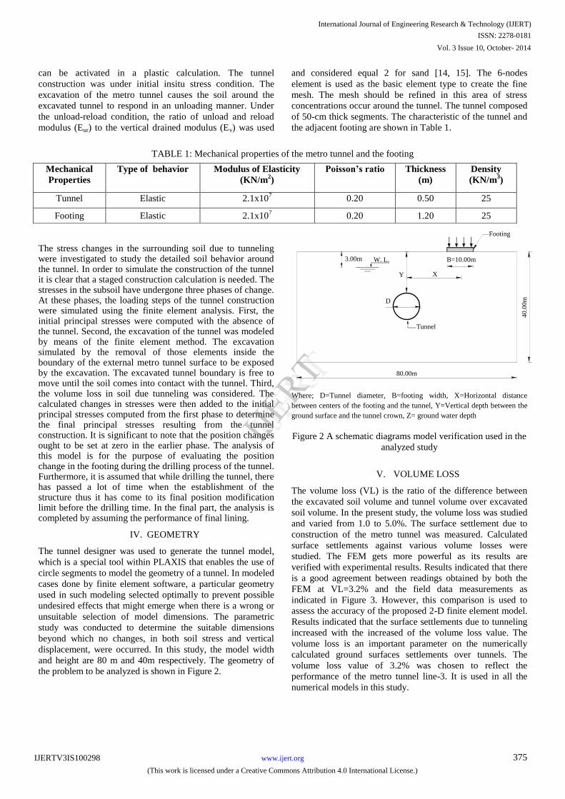
TABLE 1: Mechanical properties of the metro tunnel and the footing
The stress changes in the surrounding soil due to tunneling were investigated to study the detailed soil behavior around the tunnel. In order to simulate the construction of the tunnel it is clear that a staged construction calculation is needed. The stresses in the subsoil have undergone three phases of change. At these phases, the loading steps of the tunnel construction were simulated using the finite element analysis. First, the initial principal stresses were computed with the absence of the tunnel. Second, the excavation of the tunnel was modeled by means of the finite element method. The excavation simulated by the removal of those elements inside the boundary of the external metro tunnel surface to be exposed by the excavation. The excavated tunnel boundary is free to move until the soil comes into contact with the tunnel. Third, the volume loss in soil due tunneling was considered. The calculated changes in stresses were then added to the initial principal stresses computed from the first phase to determine the final principal stresses resulting from the tunnel construction. It is significant to note that the position changes ought to be set at zero in the earlier phase. The analysis of this model is for the purpose of evaluating the position change in the footing during the drilling process of the tunnel. Furthermore, it is assumed that while drilling the tunnel, there has passed a lot of time when the establishment of the structure thus it has come to its final position modification limit before the drilling time. In the final part, the analysis is completed by assuming the performance of final lining.
IV. GEOMETRY
The tunnel designer was used to generate the tunnel model,
which is a special tool within PLAXIS that enables the use of
circle segments to model the geometry of a tunnel. In modeled
cases done by finite element software, a particular geometry
used in such modeling selected optimally to prevent possible
undesired effects that might emerge when there is a wrong or
unsuitable selection of model dimensions. The parametric
study was conducted to determine the suitable dimensions
beyond which no changes, in both soil stress and vertical
displacement, were occurred. In this study, the model width
and height are 80 m and 40m respectively. The geometry of
the problem to be analyzed is shown in Figure 2.
B=10.00m
X
D
Tunnel
Y
W. L.
Footing
80.00m
3.00m
40.0
0m
Where; D=Tunnel diameter, B=footing width, X=Horizontal distance
between centers of the footing and the tunnel, Y=Vertical depth between the
ground surface and the tunnel crown, Z= ground water depth
Figure 2 A schematic diagrams model verification used in the
analyzed study
V. VOLUME LOSS
The volume loss (VL) is the ratio of the difference between
the excavated soil volume and tunnel volume over excavated
soil volume. In the present study, the volume loss was studied
and varied from 1.0 to 5.0%. The surface settlement due to
construction of the metro tunnel was measured. Calculated
surface settlements against various volume losses were
studied. The FEM gets more powerful as its results are
verified with experimental results. Results indicated that there
is a good agreement between readings obtained by both the
FEM at VL=3.2% and the field data measurements as
indicated in Figure 3. However, this comparison is used to
assess the accuracy of the proposed 2-D finite element model.
Results indicated that the surface settlements due to tunneling
increased with the increased of the volume loss value. The
volume loss is an important parameter on the numerically
calculated ground surfaces settlements over tunnels. The
volume loss value of 3.2% was chosen to reflect the
performance of the metro tunnel line-3. It is used in all the
numerical models in this study.
Mechanical
Properties
Type of behavior Modulus of Elasticity
(KN/m2)
Poisson’s ratio Thickness
(m)
Density
(KN/m3)
Tunnel Elastic 2.1x10⁷ 0.20 0.50 25
Footing Elastic 2.1x10⁷ 0.20 1.20 25
375
International Journal of Engineering Research & Technology (IJERT)
IJERT
IJERT
ISSN: 2278-0181
www.ijert.orgIJERTV3IS100298
(This work is licensed under a Creative Commons Attribution 4.0 International License.)
Vol. 3 Issue 10, October- 2014

Figure 3 Comparison between measured and calculated
settlements for different VL values
VI. NUMERICAL MODEL RESULTS
The model results obtained were discussed to study the effect
of different parameters on the settlement of the adjacent
footing to the tunnel. These different parameters were the
vertical and the horizontal distance between the footing and
the tunnel. Also, the effect of changing the tunnel diameter
was studied.
A. Vertical Depth between Footing and Tunnel
Variations in the depth of the tunnel located vertically
underneath the footing have been considered. Demonstration
of the settlement changes as a result of increasing the depth of
the tunnel has diameter (D=9.0m) are plotted in Figure 4.
Footing settlement was expressed in a dimensionless
parameters (S/B) where S= average footing settlement and
B=footing width. As expected, with decreasing the tunnel
depth (Y) the footing settlement was increased. This is due to
the tunneling effect which loss the soil around the tunnel.
Increasing the tunnel depth near or equal to twice the footing
width the footing settlements reduced dramatically. This is
due to the vertical stress beneath the footing rapidly reduced
with increasing the depth. Results also show that the soil
above the crown of the tunnel moves down due to the final
vertical stress moved downward. But the soil under the invert
of the tunnel heaves as a result of the soil stress reduction
which pushes the soil to move upward. There are fully agreed
with the soil movements and vertical stress change, with their
directions and magnitudes, after tunneling (D=9.0m and
Y=23.0 m) underneath a footing subjected to 100 KN/m2 as
shown in Figures 5 and 6 respectively. The vertical stress,
shown in Fig. 6, was calculated as an average stress along the
tunnel width. Also, the effective stress as principal stresses,
with an indication of their direction and relative magnitude
after tunneling for the same case is shown in Figure 7. The
plot of the effective stresses shows that an arching
phenomenon occurs around the tunnel which reduces the
stresses acting on the tunnel lining, also minims the effect of
the loosed soil around the tunnel on the footing settlements.
Figure 4 Footing settlements versus vertical tunnel depth (Y)
for different footing pressure, (D=9.0)
Figure 5 Soil movements after tunneling
45.9 KN/m2
14.5 KN/m
2
Figure 6 Vertical stress changes after tunneling
Figure 7 Effective stress changes after tunneling
Tunnel
376
International Journal of Engineering Research & Technology (IJERT)
IJERT
IJERT
ISSN: 2278-0181
www.ijert.orgIJERTV3IS100298
(This work is licensed under a Creative Commons Attribution 4.0 International License.)
Vol. 3 Issue 10, October- 2014
B. tunnel diameter
Figures 8,a and b illustrate the provided models for the
settlements of footing subjected to different pressure and
underneath by a tunnel with various diameters. It is clear that
increasing the tunnel diameter leads to increasing the footing
settlement as a result of increasing the volume loss in soil due
to tunneling. The increase in footing settlements in case of
tunnel (D=9.0m) reached to 1.2 times than that of (D=5.0m).
a) In the case of footing pressure = 10.0 KN/m
2
b) In the case of footing pressure = 100.0 KN/m
2
Figure 8 Settlements of footing versus tunnel depth (Y) for
different tunnel diameters
C. Horizontal distance between footing and tunnel
The simultaneous influence of variation in the horizontal
distance between centers of the footing and the tunnel was
considered. The model tunnel is located at different
horizontal distances from the adjacent footing (X/D =0.0, 1.0,
2.0, 2.5, and 3.0). Figure 9 shows the deformed mesh (scaled
up) at the end of the calculated phases of constructing the
tunnel (D=9.0m, Y=9.0m, and X/D=1.0) adjacent to footing
subjected to 100 KN/m2. The deformed mesh indicates a
settlement trough at the ground surface. Figure 10
demonstrates the effect of increasing the horizontal distance
between centers of the tunnel and the footing versus footing
settlements for different footing pressures. In addition, Figure
11 illustrates the footing rotation, for the same cases. It was
observed that while the horizontal distance between the
footing and the tunnel increased the footing settlements and
rotation reduced. Beyond a distance of about 2.5 times the
tunnel width, away from the tunnel center to footing center,
the influence of the tunnel becomes negligible on the footing
settlements.
Figure 9 deformed mesh after tunneling adjacent to footing
Figure 10 Footing settlements versus (X/D) for different
footing pressure (D=9.0m and Y=9.0m)
Figure 11 Footing rotation versus(X/D) for different footing
pressure (D=9.0m and Y=9.0m)
CONCLUSION
Based on the above soil investigations and Cairo metro-Line-
3 tunnel, the following conclusions were reached:
1- A 2-D numerical model with PLAXIS 8.6 program is
a good tool for investigating the performance of the
footing settlements adjacent to the tunnel.
2- The influence of the tunnel becomes negligible on the
adjacent footing settlements beyond a horizontal
distance of about 2.5 times the tunnel width or a
vertical depth equal to twice the footing width.
3- The volume loss of soil due to tunneling is an
important parameter in tunnel numerical models to
predict the ground settlements. It is recommended a
volume loss value equal 3.2 % for the Cairo metro-
Line-3.
4- The footing settlements due to tunneling (D=9.0m)
reached to 1.2 times than that of tunnel (D=5.0m).
377
International Journal of Engineering Research & Technology (IJERT)
IJERT
IJERT
ISSN: 2278-0181
www.ijert.orgIJERTV3IS100298
(This work is licensed under a Creative Commons Attribution 4.0 International License.)
Vol. 3 Issue 10, October- 2014
5- The soil above the crown of the tunnel moves down
however the soil under the invert of the tunnel moves
upward.
REFERENCES
1 Lee, C. J., Chiang, K. H., and Kuo, C. M., “Ground
movement and tunnel stability when tunneling in
sandy ground”, Journal of the Chinese Institute of
Engineers, Vol. 27, No. 7, pp. 1021–1032, 2004.
2 Mazek, S. A., Law, K. T., and Lau, D. T., “Effect of
grouting on soil reinforcing and tunnel deformation”,
International underground infrastructure research
conference, Waterloo University, Kitchener, Canada,
2001a.
3 Azadi, M., Pourakbar, S., and Kashfi, A.,
“Assessment of optimum settlement of structure
adjacent urban tunnel by using neural network
methods”, Tunnelling and underground space
technology, Vol. 37, pp. 1-9, 2013.
4 Abu-Krisha, A., “Settlement control of CWO Sewer
tunnel during boring El-Azhar road tunnels in Cairo”
Proceeding of the international world to congress
Milano, pp. 3–9, 2001.
5 Abu-Farsakh, M. Y., Tumay, M. T., Fellow ASCE.
“Finite element analysis of ground response due to
tunnel excavation in soils”, Proceeding of the
international journal for numerical and analytical
methods in geomechanics engineering, Ain Shams
University, Egypt, Vol. 23.,pp. 524–5, 1999.
6 Shahram, P., Mohammad, A., Bujang, H., and
Afshin, A., “Estimation of Adjacent Building
Settlement During Drilling of Urban Tunnels”, The
Electronic Journal of Geotechnical Engineering, Vol.
19, pp. 469-479, 2014.
7 Mazek, S. A., Almannaei, H. A., “Finite element
model of Cairo metro tunnel-Line 3 performance ”,
Ain Shams Engineering Journal, Vol. 4, pp. 709-716,
2013.
8 Darabi, A., Ahangari, K., Noorzad, A., and Arab,
A., “Subsidence estimation utilizing various
approaches – a case study: Tehran No. 3 subway
line”, Tunnelling Underground Space Technology,
Vol. 31, pp. 117–127, 2012.
9 Liu Jiangfeng, Qi Taiyue, and Wu Zhanrui, “Analysis
of ground movement due to metro station driven with
enlarging shield tunnels under building and its
parameter sensitivity analysis”, Tunnelling and
Underground Space Technology, Vol. 28, pp. 287–
296, 2012.
10 Wang Zhechao, Wong Ron C. K., Li Shucai, and
Qiao Liping, “Finite element analysis of long-term
surface settlement above a shallow tunnel in soft
ground”, Tunnel Underground Space Technol, Vol.
30, pp. 85–92, 2012.
11 Brinkgreve, R. B. J., and Vermeer, P. A., “Plaxis-
finite element code for soil and rock analysis”,
Version 8.6 Plaxis B. V., The Netherlands, 1998.
12 National Authority for Tunnels (NAT), Project
Document, 2009.
13 Duncan, J. M., and Chang, C.Y., “Nonlinear analysis
of stress and strain in soils”, Journal of the Soil
Mechanics and Foundations Division, ASCE, Vol.
96(SM5), pp. 1629-1653, 1970.
14 Duncan, J. M., Byrne, P. M., Wong, K. S., and
Mabry, P., “Strength, stress strain, and bulk modulus
parameters for finite element analysis of stresses and
movements in soil masses”, University of California,
Berkeley, CA Report No. UCB/GT/80-01, 1980.
15 Byrne, P. M., Cheung, H., and Yan, L., “Soil
parameters for deformation analysis of sand masses”,
Canadian Geotechnical Journal, Vol. 24, pp. 366–
376, 1987.
378
International Journal of Engineering Research & Technology (IJERT)
IJERT
IJERT
ISSN: 2278-0181
www.ijert.orgIJERTV3IS100298
(This work is licensed under a Creative Commons Attribution 4.0 International License.)
Vol. 3 Issue 10, October- 2014
