investigation of mesh phasing in a planetary gear train...
TRANSCRIPT
Investigation of mesh phasing in a planetary gear train using combined FE and Multibody simulations
S. Shweiki1, D. Mundo
1, J. Korta
1,2, P. Oranges
1, A. Palermo
1
1 Department of Mechanical, Energy and Management Engineering, University of Calabria, Via P. Bucci
Cubo 46C, 87036 Arcavacata di Rende (CS), Italy
email: [email protected]
2 AGH University of Science and Technology, al. A. Mickiewicza 30, 30-059 Krakow, Poland
Abstract
In this paper, we propose the employment of the Finite Element (FE) method in combination with MB
simulation technique, in order to analyse the dynamic characteristics of a planetary gear. The described
approach consists of two steps: first, a static transmission error curve is generated using nonlinear static
FE simulations and, subsequently, MB analyses are performed on a three-dimensional model of the
transmission. The described simulation approach is applied to analyse the dynamic behaviour of the
planetary stage of a wind turbine transmission model, in order to minimize unwanted vibrations and
improve system dynamics by using different mesh phasing sequences of the planets. The obtained results
allow assessing the degree of sensitivity of the dynamic behaviour of the analysed gearbox to this
important design parameter, i.e. planet mesh phasing, and the applicability of the proposed modelling
approach for the improvement of the dynamic behaviour of planetary gearbox systems.
1 Introduction
Mechanical transmissions are extensively used in many industrial applications, attracting the interest of
researchers and engineers, who dedicated consistent resources and efforts since the second half of the past
century to investigate the multiple and interconnected phenomena that are typical in transmission
dynamics. In several high-technology areas, such as transportation, energy production and industrial
automation, product and process sustainability, with a main focus on impact on the environment, has
become a key factor in assessing system performance. Mechanical transmissions play a crucial role in all
the technological areas mentioned above. For this reason, although extensively studied in the last decades,
system-level dynamics of the full mechanical transmission is gaining a game-changer role and requires a
deeper understanding and a more detailed knowledge to allow designers addressing at the same time
multiple and even conflicting performance attributes.
Planetary gears are a specific class of epicyclic gear sets, commonly employed in several applications
related to automotive, aerospace and wind turbine industries, thanks to the high value of power-to-weight
ratio enabled by the presence of multiple planet branches. Additional advantages come from their axi-
symmetric and compact configuration, which allows accommodating wider manufacturing tolerances [1]
and results, typically, in lower levels of noise and vibrations (N&V) [2] in comparison with fixed-axis
gearboxes. Moreover, the possibility to generate a different speed ratios by simply commuting the input,
output and reaction members of the train makes planetary gearboxes the preferred choice in several
applications, such as automatic transmissions in automobiles.
In the last decades, a wide literature was dedicated to the investigation of the dynamic behaviour of
planetary gears, with the aim of understanding the crucial aspects, which strongly affect the reliability and
N&V performance of the transmission.
A review of the scientific literature addressing the different aspects of planetary and epicyclic gear
dynamics is provided by Cooley and Parker in [3]. Mathematical models able to provide dynamic response
1407
predictions that include nonlinear phenomena and mesh stiffness fluctuations are reviewed and different
aspects, including elastic compliance, gyroscopic effects, planet load sharing and mesh phasing, are
discussed. Recently, several researchers studied the significant impact that planet mesh phasing has on the
dynamic response of planetary gearboxes. Canchi and Parker [4] studied the effects of mesh phasing and
contact ratio on the vibration resonances of a planetary gear ring, with the aim of identifying those
conditions that allow suppressing the instabilities linked to the parametric excitation of the rotating ring
subject to moving time-varying stiffnesses. Two different 2D predictive models, a lumped-parameter
model and a FE model, were used in [5] to analyse the complex, nonlinear dynamic behaviour of spur
planetary gears. The authors show that a proper mesh phasing allows to suppress rotational and
translational vibrations even when nonlinearity from tooth contact loss occurs, but mesh phasing rules are
not valid in the regions where a chaotic behaviour is predicted.
Parker and Lin derived the analytical relationships that allow to properly incorporate mesh phasing in the
analytical models of planetary and epicyclic gears [6], while a physical explanation of vibration
suppression by planet phasing was provided by Parker in [7], based on the analysis of the dynamic forces
acting at the sun-planet and ring-planet meshes, which enabled the identification of simple rules for the
suppression of a particular harmonic of the mesh frequency in the dynamic response.
In [8] Kahraman proposed a simulation model of a single-stage planetary gear with helical gears, which
allows describing the effects of the planet mesh phasing conditions on the dynamic behaviour of a four-
planet system. An analytical procedure for contact analysis of gear meshing, based on plate deflection
models, was used by Kartik and Houser in [9] to predict the load distribution and transmission error in
multiple-mesh gear-trains. The proposed model allows taking into account mesh phasing, thus enabling an
assessment of its effects on the dynamic behaviour of planetary gear trains and split-path transmissions.
Another behaviour that most measured vibration and noise data from planetary gear transmissions exhibit,
namely modulation sidebands, has been studied by Inapolat and Kahraman in [10], where the authors
provide a detailed investigation of the mechanisms that are behind such a typical dynamic phenomenon
exhibited by planetary transmissions.
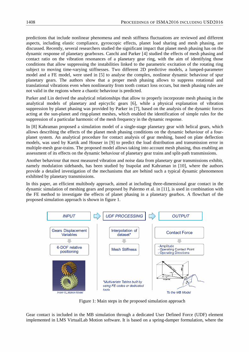
In this paper, an efficient multibody approach, aimed at including three-dimensional gear contact in the
dynamic simulation of meshing gears and proposed by Palermo et al. in [11], is used in combination with
the FE method to investigate the effects of planet phasing in a planetary gearbox. A flowchart of the
proposed simulation approach is shown in figure 1.
Figure 1: Main steps in the proposed simulation approach
Gear contact is included in the MB simulation through a dedicated User Defined Force (UDF) element
implemented in LMS VirtualLab Motion software. It is based on a spring-damper formulation, where the
1408 PROCEEDINGS OF ISMA2016 INCLUDING USD2016

actual value of the mesh stiffness is interpolated from a dataset calculated for a discretized range of
operating conditions and stored in multivariate look-up tables. This is achieved in a preparation phase,
where a series of non-linear Finite Element (NLFE) static simulations of the meshing gears are run for a
discrete number of relative ring-planet and planet-sun angular positions along the meshing cycle. The aim
is to compute the static transmission error (STE) curves, from which the mesh stiffness is derived. In this
way, time-demanding NLFE simulations are limited to a pre-processing phase, without jeopardizing the
computational efficiency of gear meshing dynamic simulations, carried out in the MB environment.
The outline of the paper is as follows. In section 2, the two main steps of the simulation approach, i.e. the
MB dynamic simulation of gear meshing and the estimation of STE curves by NLFE static simulations,
are described. Section 3 provides a description of the case-study analysed in this work, consisting of a
planetary gear derived from a wind-turbine gearbox application. Simulation results are illustrated in
section 4, while the concluding remarks in section 5 close the paper.
2 Multibody dynamic simulation of gear meshing
Dynamic simulations of gear meshing, aimed at assessing the effects of planet phasing on the dynamic
transmission error (DTE) of the planetary stage, were carried out by using a dedicated UDF element
implemented in MB simulation environment. This section provides a brief description of the proposed
contact formulation, while full details can be found in [11]. The approach used to estimate the STE curves
of meshing gears, to be used in the MB environment to calculate the actual value of the time-varying mesh
stiffness, is described as well.
2.1 Multibody formulation of gear meshing
In the proposed approach, a UDF element used for MB simulation of gear meshing is defined for each
gear pair in the model. It computes the meshing forces derived from the instantaneous conditions and
determines the proper load location on the teeth flanks at the subsequent step of the dynamic simulation.
The process of contact force determination starts with the computation of the DTE between the gears and
its time derivative. The DTE is derived by comparing the position of two reference systems connected to
the gear bodies with the position of a third reference system for each time step of the simulation. It is
computed in a transverse plane, which is tangential to the pitch circles of the meshing gears, as the relative
displacement between the two reference frames in the tangential direction and accounts for two different
contributions: the relative rotations of the two meshing gears (𝐷𝑇𝐸𝑟) and the relative translation in the
tangential direction (𝐷𝑇𝐸𝑡), according to the following equation:
𝐷𝑇𝐸 = 𝐷𝑇𝐸𝑟 + 𝐷𝑇𝐸𝑡 (1)
The gear contact force defined by the UDF element is derived from the DTE according to the following
formulation:
{
𝐹𝑡𝑡𝑻 = 𝑭𝐹𝑡𝑡 = 𝐹𝑡𝑡𝑘 + 𝐹𝑡𝑡𝑐𝐹𝑡𝑡𝑘 = 𝑘𝐷𝑇𝐸
𝐹𝑡𝑡𝑐 = 𝑐𝑑𝐷𝑇𝐸
𝑑𝑡
(2)
where 𝑭 is the normal contact force, 𝐹𝑡𝑡 is the magnitude of the tangential contact force and 𝑻 is the
transformation vector from the tangential direction to the direction normal to the tooth surface in the force
application point. 𝐹𝑡𝑡𝑘 and 𝐹𝑡𝑡𝑐 represent the elastic and the damping components of the tangential contact
force. The constants k and c are the instantaneous mesh stiffness and the viscous damping coefficient
respectively. The transformation vector, which allows computing the radial, the tangential and the axial
components of the contact force for a pair of helical gears, is defined as:
FP7 DEMETRA: DESIGN OF MECHANICAL TRANSMISSIONS 1409
𝑻 = {𝑡𝑎𝑛𝜑𝑛/𝑐𝑜𝑠𝛽
1−𝑡𝑎𝑛𝛽
} (3)
where 𝛽 and 𝜑𝑛 are the helix and the normal pressure angles respectively.
The meshing force is applied in the operating contact point, which is always located at the operating pitch
point in the transversal plane according to the proposed formulation. In the case study analysed in this
work, the operating contact point is considered to be always located in the middle plane of each gear,
which implies neglecting shuttling phenomena.
Under the assumption that the external load is constant, the time-varying nature of the mesh stiffness is
taken into account by calculating it, at each time step in the simulation, as:
𝑘(𝑃𝑀𝐶, 𝐶𝐷,𝑀) =𝐹𝑡𝑡𝑛
𝑆𝑇𝐸(𝑃𝑀𝐸,𝐶𝐷,𝑀)/ cos𝜑𝑡 (4)
where PMC, CD and M are the actual values of the position along the meshing cycle, of the gears centre
distance and angular misalignment in the plane of action respectively. In the case study analysed in this
paper, ideal revolute joints are used in the model, which prevent the gear rotational axes from any parallel
and angular misalignment, while the PMC, which assumes values in the range between 0 and 1, is
calculated at each time step as:
𝑃𝑀𝐶 =1
𝜃𝑃1[|𝜃1+ 𝜃1𝑠| − 𝑓𝑙𝑜𝑜𝑟 (
|𝜃1+ 𝜃1𝑠|
𝜃𝑃1) 𝜃𝑃1] (5)
where 𝜃1 is the actual rotation of one of the meshing gears, 𝜃𝑃1 is its angular pitch and 𝜃1𝑠 is its initial
angular position. By setting proper values for the latter parameter, different ring-planet and sun-planet
phasing strategies can be tested in planetary gears, as it will be illustrated in the next section.
In the approach proposed here, the STE curves for each pair, to be used for the estimation of the mesh
stiffness according to equation 4, are calculated through static NLFE simulations, as described in the
following sub-section.
2.2 Estimation of STE curves by NLFE simulations
The transmission error (TE) is considered as one of the main excitation sources in a system where
meshing gears are present. It is defined as “the difference between the angular position that the output
shaft of a drive would occupy if the drive were perfect and the actual position of the output” [12]. It is
commonplace to translate such a difference in angles into a linear displacement, according to the
following formulation:
𝑇𝐸 = 𝑟𝑏𝐺𝜃𝐺 − 𝑟𝑏𝑃𝜃𝑃 (6)
where 𝜃𝑃 and 𝜃𝐺 represent the rotation of the pinion and of the gear respectively, while 𝑟𝑏𝑃 and 𝑟𝑏𝐺 are
their base radii.
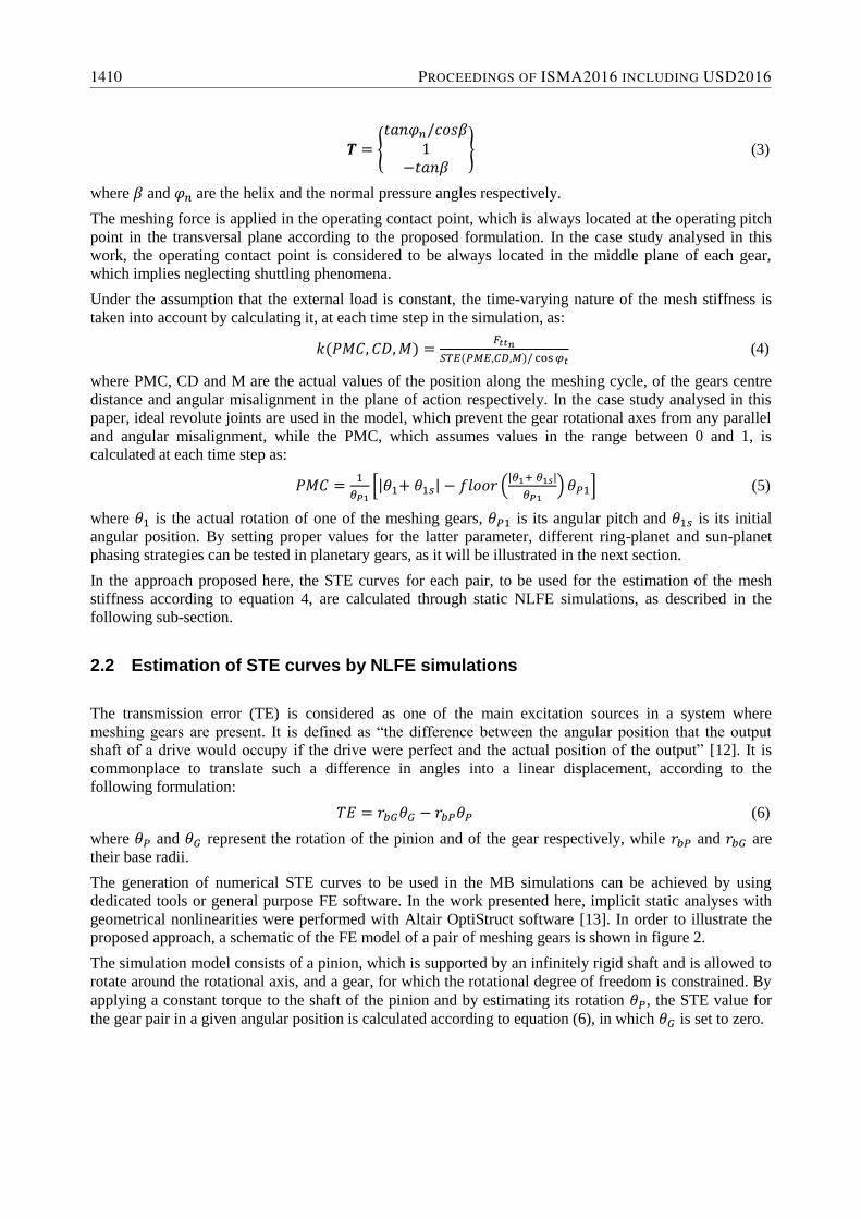
The generation of numerical STE curves to be used in the MB simulations can be achieved by using
dedicated tools or general purpose FE software. In the work presented here, implicit static analyses with
geometrical nonlinearities were performed with Altair OptiStruct software [13]. In order to illustrate the
proposed approach, a schematic of the FE model of a pair of meshing gears is shown in figure 2.
The simulation model consists of a pinion, which is supported by an infinitely rigid shaft and is allowed to
rotate around the rotational axis, and a gear, for which the rotational degree of freedom is constrained. By
applying a constant torque to the shaft of the pinion and by estimating its rotation 𝜃𝑃, the STE value for
the gear pair in a given angular position is calculated according to equation (6), in which 𝜃𝐺 is set to zero.
1410 PROCEEDINGS OF ISMA2016 INCLUDING USD2016

Figure 2: Schematic of the FE-based approach used to estimate STE curves
3 Case-study description
In order to show the capabilities of the simulation methodology proposed in this work to analyse the
effects of planet phasing on the dynamic behaviour of an epicyclic gear, a planetary gear set, derived from
a wind turbine application case, was analysed. The MB model of the gear train is shown in figure 3. The
main macro-geometry parameters are listed in Table 1, while involute profiles, without any modifications,
were assumed for the teeth. This model was built starting from the low speed stage of the MB model of
the GRC 750 kW gearbox, with design layout characteristics that are typical for current multi-megawatt
wind turbines, used by the National Renewable Energy Laboratory (NREL) in the Gearbox Reliability
Collaborative [14].
Root
diameter
[mm]
Helix
angle
[deg]
Number of
teeth
Face width
[mm]
Pressure
angle [deg]
Planets 372 7.5 L 39 227.5
20 Ring 1047 7.5 L 99 230
Sun gear 186 7.5 R 21 220
Table 1: Macro-geometry parameters for the analysed planetary stage.
Figure 3: MB model of the analysed planetary gearbox
In this model six gear contact elements are present, which are intended to model the contact between the
ring and the three planets and between the latter and the sun.With the aim of focusing on the effects of
planet phasing on the torsional behaviour of the planetary stage and hence on the DTE between input and
output shafts, while keeping the overall inertia properties of the full transmission unchanged, a proper
rotational inertia value was estimated by analysing the entire gearbox on both sides of the planetary stage
FP7 DEMETRA: DESIGN OF MECHANICAL TRANSMISSIONS 1411

and lumped on each of the two shafts. Ideal rotational joints, instead of bushings, were used to model
planet-carrier, sun-housing and carrier-housing connections, while a bracket joint prevents the ring from
any displacement. Therefore, in such a simplified model, the compliance of structural components,
bearings and mountings is neglected. The periodic, time-varying gear mesh stiffness, which is recognized
as one of the main internal excitation sources in a mechanical transmission, is taken into account in the
MB simulation environment by the dedicated UDF element.
As described in section 2, in a preliminary phase the FE models of ring-planet and planet-sun pairs were
built by using 8-node hexahedral elements and analysed through static NLFE simulations that allowed
estimating the STE curves. Examples of contact stress distributions on the ring and on the planet analysed
in a given configuration are shown in figure 4, while the estimated STE curves for the ring-planet and for
the planet-sun pairs are illustrated in figure 5 respectively. Each STE curve was built by analysing the gear
pair in a set of 50 angular positions, equally distributed along the meshing cycle. For both gear pairs, the
static simulations were executed by considering the supporting shafts as infinitely rigid, by applying a 45
kNm torque on the planet and by keeping the other gear (sun or ring) stationary by constraining all the
degrees of freedom of central nodes through rigid connection elements. The results of the static
simulations are shown in figure 4, where the STE estimated for the ring-planet and planet-sun pairs are
represented as a function of the gears position along the meshing cycle.
a) b)
Figure 4: Examples of contact stress distributions on the ring and on the planet in a given configuration.
a) b)
Figure 5: STE curves estimated for ring-planet pair (a) and sun-planet pair (b)
4 MB simulation and results
With the aim of investigating the effects of planet mesh phasing, two different configurations of the
planetary were analysed, the in-phase and the sequentially-phased planets configurations. To properly set
relative phasing between ring-planet and planet-sun meshes, the kinematic relationships between the
relative positions of the different elements of planetary stages, described by Parker and Lin in [6], were
1412 PROCEEDINGS OF ISMA2016 INCLUDING USD2016
used. Such relations allow calculating mesh phasing based on the geometrical proprieties and assembly
requirements of the planetary. Three quantities completely describe the relative position of the
transmission components in a planetary stage, which are typically normalized with respect to the angular
pitch: the relative phase 𝛾𝑠𝑛 between the nth sun-planet mesh and the 1
st sun-planet mesh; the relative phase
𝛾𝑟𝑛 between the nth
ring-planet mesh and the 1st
ring-planet mesh; and the relative phase 𝛾𝑟𝑠 between the
sun-planet and the ring-planet meshes for a given planet,which is equal for all the planets. According to
the configuration of the planetary set analysed in this work, where the ring is fixed and the carrier is the
input element, the first two phase parameters are defined by the following equations:
γ𝑠𝑛 = 𝑧𝑠𝜓𝑛
2𝜋 (7)
γ𝑟𝑛 = − 𝑧𝑟𝜓𝑛
2𝜋 (8)
where 𝜓𝑛is the circumferential orientation of the planets into the carrier and 𝑧𝑟and 𝑧𝑠 are the teeth number
of the ring and of the sun gear respectively. To fulfil assembly constraints, 𝜓𝑛 has to be an integer
multiple of the least mesh angle according to the following equation:
𝜓𝑛 = 𝑝𝑛2𝜋
𝑍𝑟+𝑍𝑠 (9)
where 𝑝𝑛is an integer that varies from planet to planet.
The relative phase 𝛾𝑟𝑠 between the the sun-planet and the ring-planet meshes for a given planet is
calculated using the analytical formulation described in [6], which gives, for the case-study analysed in
this paper, a value of γrsequal to 0.2805, corresponding to an angular phase of 2.589 deg.
Ring-planet and planet-sun mesh phases calculated for the two different phasing strategies are listed in
table 2, along with 𝑝𝑛values chosen to generate in-phase and sequentially-phased configurations. It is
worthy to notice that the former configuration corresponds to a planetary with equally-spaced planets.
𝒑𝟏 𝒑𝟐 𝒑𝟑 𝛄𝐬𝟏 𝛄𝐬𝟐 𝛄𝐬𝟑 𝛄𝐫𝟏 𝛄𝐫𝟐 𝛄𝐫𝟑
In-phase 0 40 80 0 0 0 0.2805 0.2805 0.2805
Seq-phase 0 42 84 0 0.35 0.70 0.2805 0.9305 0.5805
Table 2: Ring-planet and planet-sun mesh phasing for in-phase and sequentially-phased configurations
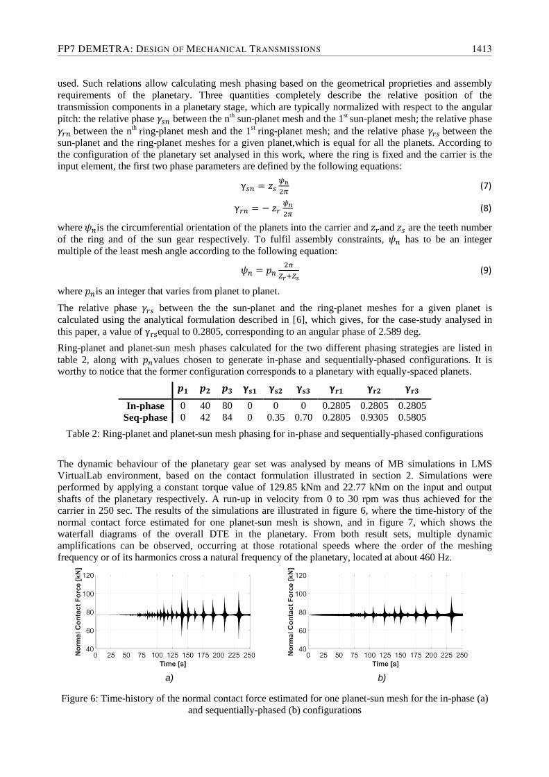
The dynamic behaviour of the planetary gear set was analysed by means of MB simulations in LMS
VirtualLab environment, based on the contact formulation illustrated in section 2. Simulations were
performed by applying a constant torque value of 129.85 kNm and 22.77 kNm on the input and output
shafts of the planetary respectively. A run-up in velocity from 0 to 30 rpm was thus achieved for the
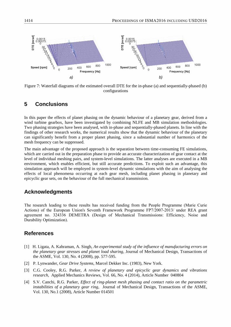
carrier in 250 sec. The results of the simulations are illustrated in figure 6, where the time-history of the
normal contact force estimated for one planet-sun mesh is shown, and in figure 7, which shows the
waterfall diagrams of the overall DTE in the planetary. From both result sets, multiple dynamic
amplifications can be observed, occurring at those rotational speeds where the order of the meshing
frequency or of its harmonics cross a natural frequency of the planetary, located at about 460 Hz.
a) b)
Figure 6: Time-history of the normal contact force estimated for one planet-sun mesh for the in-phase (a)
and sequentially-phased (b) configurations
FP7 DEMETRA: DESIGN OF MECHANICAL TRANSMISSIONS 1413
a) b)
Figure 7: Waterfall diagrams of the estimated overall DTE for the in-phase (a) and sequentially-phased (b)
configurations
5 Conclusions
In this paper the effects of planet phasing on the dynamic behaviour of a planetary gear, derived from a
wind turbine gearbox, have been investigated by combining NLFE and MB simulation methodologies.
Two phasing strategies have been analysed, with in-phase and sequentially-phased planets. In line with the
findings of other research works, the numerical results show that the dynamic behaviour of the planetary
can significantly benefit from a proper planet phasing, since a substantial number of harmonics of the
mesh frequency can be suppressed.
The main advantage of the proposed approach is the separation between time-consuming FE simulations,
which are carried out in the preparation phase to provide an accurate characterization of gear contact at the
level of individual meshing pairs, and system-level simulations. The latter analyses are executed in a MB
environment, which enables efficient, but still accurate predictions. To exploit such an advantage, this
simulation approach will be employed in system-level dynamic simulations with the aim of analysing the
effects of local phenomena occurring at each gear mesh, including planet phasing in planetary and
epicyclic gear sets, on the behaviour of the full mechanical transmission.
Acknowledgments
The research leading to these results has received funding from the People Programme (Marie Curie
Actions) of the European Union's Seventh Framework Programme FP7/2007-2013/ under REA grant
agreement no. 324336 DEMETRA (Design of Mechanical Transmissions: Efficiency, Noise and
Durability Optimization).
References
[1] H. Ligata, A. Kahraman, A. Singh, An experimental study of the influence of manufacturing errors on
the planetary gear stresses and planet load sharing, Journal of Mechanical Design, Transactions of
the ASME, Vol. 130, No. 4 (2008), pp. 577-595.
[2] P. Lynwander, Gear Drive Systems, Marcel Dekker Inc. (1983), New York.
[3] C.G. Cooley, R.G. Parker, A review of planetary and epicyclic gear dynamics and vibrations
research, Applied Mechanics Reviews, Vol. 66, No. 4 (2014), Article Number 040804
[4] S.V. Canchi, R.G. Parker, Effect of ring-planet mesh phasing and contact ratio on the parametric
instabilities of a planetary gear ring, Journal of Mechanical Design, Transactions of the ASME,
Vol. 130, No.1 (2008), Article Number 014501
1414 PROCEEDINGS OF ISMA2016 INCLUDING USD2016
[5] V.K. Ambarisha, R.G. Parker, Nonlinear dynamics of planetary gears using analytical and finite
element models, Journal of Sound and Vibration, Vol. 302, No. 3 (2007), pp. 577-595.
[6] R.G. Parker, J. Lin, Mesh phasing relationships in planetary and epicyclic gears, Journal of
Mechanical Design, Transactions of the ASME, Vol. 126, No. 2 (2004), pp. 365-370.
[7] R.G. Parker, Physical explanation for the effectiveness of planet phasing to suppress planetary gear
vibration, Journal of Sound and Vibration, Vol. 236, No. 4 (2000), pp. 561-573.
[8] A. Kahraman, Planetary gear train dynamics, Journal ofMechanical Design, Transactions Of the
ASME, Vol. 116, No. 3 (1997), pp. 713-720.
[9] V. Kartik, D.R. Houser, Analytical predictions for the transmission error excitation in various
multiple-mesh gear-trains, Proceedings of the ASME Design Engineering Technical Conference,
(2003), pp. 515-524.
[10] M. Inalpolat, A. Kahraman, A theoretical and experimental investigation of modulation sidebands of
planetary gears, Journal of Sound and Vibration, Vol. 323, (2009), pp. 677–696.
[11] A. Palermo, D. Mundo, R. Hadjit, W. Desmet, Multibody element for spur and helical gear meshing
based on detailed three-dimensional contact calculations, Mechanism and Machine Theory, Vol. 62,
(2013), pp. 13–30.
[12] J. D. Smith, Gear noise and vibration. Marcel Dekker (2003), Cambridge.
[13] J. Korta, A. Palermo, D. Mundo, S. Shweiki, Combining Finite Element and Multibody Modelling
Techniques for Time-Efficient Simulation of Nonlinear Gear Dynamics, Proceedings of the Seventh
International Conference on Advances in System Simulation SIMUL 2015, (2015), Barcelona (Spain).
[14] J. Keller and R. Wallen, Gearbox Reliability Collaborative Phase 3 Gearbox 2 Test Report, National
Renewable Energy Laboratory Technical Report, NREL/TP-5000-63693, (2015).
FP7 DEMETRA: DESIGN OF MECHANICAL TRANSMISSIONS 1415

1416 PROCEEDINGS OF ISMA2016 INCLUDING USD2016