investigation of the effects of profile shift in helical ...same mechanism were verified by using...
TRANSCRIPT

World Journal of Mechanics, 2018, 8, 200-209 http://www.scirp.org/journal/wjm
ISSN Online: 2160-0503 ISSN Print: 2160-049X
DOI: 10.4236/wjm.2018.85015 May 22, 2018 200 World Journal of Mechanics
Investigation of the Effects of Profile Shift in Helical Gear Mechanisms with Analytical and Numerical Methods
Gultekin Karadere1, Ilhan Yilmaz1,2
1Department of Mechanical Engineering, Faculty of Engineering, Uludag University, Bursa, Turkey 2 Borcelik Celik Sanayii Ticaret A.S., Bursa, Turkey
Abstract
In this paper, the effects of profile shift in cylindrical helical gear mechanisms have been investigated with numerical and analytical calculations. The ma-thematical model for computer simulation of gears has been designed and the numerical calculations have been carried out. Analytical calculations have been made with an excel program which was designed at different profile shift coefficients for a selected mechanism. Analytical calculations of the same mechanism have been verified by using ANSYS 14.5. The results of analytical and numerical solutions have been compared to profile shift coefficients.
Keywords
Profile Shift, Cylindrical Helical Gears, Tooth Root Stress, Hertzian Contact Stress, Finite Element Analysis, ANSYS
1. Introduction
Cylindrical gears are essential machine elements and widely used in many fields, such as wind power, coastal ships, automotive products, and general gear boxes. The helical gears offer considerable advantages for high speed and heavy-duty gear drives. For helical gears the total contact ratio is higher owing to the axial tooth overlap. Helical gears, therefore, tend to have greater load-carrying capac-ity compared with spur gears which material, quality of manufacture, lubrica-tion, type of loading, and other factors are the same. They also possess the ability to a much smoother and quieter running [1] [2].
Helical gears produce an end thrust along the axis of the shafts in addition to
How to cite this paper: Karadere, G. and Yilmaz, I. (2018) Investigation of the Ef-fects of Profile Shift in Helical Gear Me-chanisms with Analytical and Numerical Methods. World Journal of Mechanics, 8, 200-209. https://doi.org/10.4236/wjm.2018.85015 Received: February 1, 2018 Accepted: May 19, 2018 Published: May 22, 2018 Copyright © 2018 by authors and Scientific Research Publishing Inc. This work is licensed under the Creative Commons Attribution International License (CC BY 4.0). http://creativecommons.org/licenses/by/4.0/
Open Access

G. Karadere, I. Yilmaz
DOI: 10.4236/wjm.2018.85015 201 World Journal of Mechanics
the separating and tangential (driving) loads of spur gears, where suitable means can be provided to take this thrust, such as thrust collars or ball or tapered-roller bearings; it is no great disadvantage. The axial load increases as the helix angle increases. Helix angles typically range from 15˚ to 45˚. At high values of helix angle (for 45˚), the improvement in noise tends to peak [3].
There are two basic strength calculations for two primary fatigue related fail-ure modes in the design of gear. The first is to calculate the maximum bending stress which leads to fracture at the root of the gear tooth. The most common type of surface failure is pitting which is caused by the repeating high contact stress (Hertz surface pressure). The second job is to calculate the maximum sur-face pressure [3].
Profile shift is used by designers for many reasons including the elimination of undercut when hobbing or shaping gears with few teeth, increasing the load carrying capacity or the lifetime of the gears, decreasing the noise level, increas-ing or decreasing the center distance and changing tooth thickness. Profile shift—sometimes known as “addendum modification”—is the displacement of the basic rack (or cutting tool) datum line from the reference diameter of the gear. The size of the profile shift is usually made to be non-dimensional by di-viding it by the normal module, and it is then defined by the profile shift coeffi-cient “x”. A positive profile shift increases the tooth thickness while a negative profile shift reduces tooth thickness.
Some of the studies done recently on profile shift in cylindrical gear mechan-isms have been mentioned below.
Antal et al. presented a new method for the determination of the specific ad-dendum modifications at helical gears. The method is based on the equalization of the relative velocities at the points where the meshing of the teeth begins and ends [4].
Senthil Kumar et al. worked on optimization of asymmetric spur gear drives to improve the bending load capacity. They concluded that the optimum value of profile shift coefficient for pinion increased with the increase in the values of speed ratio and teeth number in pinion [5].
Mallesh et al. investigated the effect of profile shift in asymmetric spur gears on tooth root bending stress by finite element analysis [6].
Magalhaes et al. investigated the influence of tooth profile and oil formulation on gear power loss. In the study mentioned the power losses reduction has been obtained using two different approaches: using lower modulus helical gears and significant positive profiles shifts and using gear oil formulations with different base oils [7].
Baglioni et al. investigated the influence of the addendum modification on spur gear efficiency [8].
Li et al. worked on optimal selection of addendum modification coefficients of involute cylindrical gears [9].
In this paper, the effects of profile shift in cylindrical involute helical gear mechanisms have been investigated with numerical and analytical calculations.

G. Karadere, I. Yilmaz
DOI: 10.4236/wjm.2018.85015 202 World Journal of Mechanics
The mathematical model for computer simulation of helical gears has been de-signed and the numerical calculations have been carried out. Analytical calcula-tions were made with an excel program which was designed at different profile shift coefficients for a selected gear mechanism. Analytical calculations of the same mechanism were verified by using ANSYS 14.5. In this paper, the effects of profile shift coefficient on parameters such as center distance, normal pressure angle, transverse contact ratio, pinion tooth root stress, gear tooth root stress, Hertzian contact stress (surface pressure at tooth flank) in helical gear mechan-isms have been investigated with numerical and analytical methods. Analytical solutions have been carried out according to DIN 3990. Numerical solutions have been performed using the finite element method. The most realistic mod-eling of the operation of the all gear mechanism has been done with the aid of three-dimensional finite-element analysis. It has also not been applied any ex-ternal load. The results of analytical and numerical solutions have been com-pared to profile shift coefficients [10].
2. Methodology
In analytical solutions, initially, module and other size calculations are done for helical gear mechanism given in Table 1. In gear systems, there has not been any change except profile shift coefficients. Input parameters of gear systems, the main geometric dimensions and tooth forces remained constant. Center dis-tances, pressure angles, transverse contact ratios, pinion tooth root stresses, gear tooth root stresses, Hertzian contact stresses have been calculated according to DIN 3990.
According to the data in Table 1, the module and the number of teeth of gear were chosen as m = 5 and zg = 59. Pinion profile shift coefficient (xp) is selected according to the following equation proposed by DIN 3992 where xg represents gear profile shift coefficient [11]. Table 1. Properties of selected in volute helical gear mechanism.
Input power P 45 kW
Input speed n1 1500 rpm
Output speed n2 410 rpm
Normal pressure angle αn 20˚
Helix angle β 15˚
Number of teeth of the pinion zp 16
Facewidth/Reference diameter ψd = b/d 0.7
Material of the pinion
20 MnCr5 (Case-hardening steel)
Material of the gear
16 MnCr5 (Case-hardening steel)
Drive system
Electric motor
Operating conditions
Moderate impact
G. Karadere, I. Yilmaz
DOI: 10.4236/wjm.2018.85015 203 World Journal of Mechanics
log0.5
2 2log
100
g
pp g p gp
p g
zzx x x x
xz z
+ + ≈ + − ⋅
⋅ (1)
Thus, tooth root stresses for the pinion and the gear have been expected in the near values. The most frequently used numerical method is the finite element method, as can be seen from many papers [12]. Numerical solutions were made with the program ANSYS 14.5.
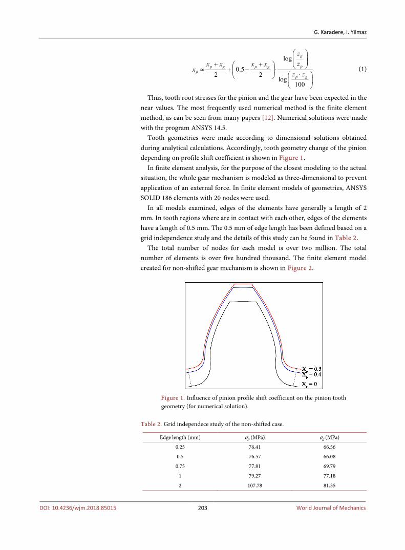
Tooth geometries were made according to dimensional solutions obtained during analytical calculations. Accordingly, tooth geometry change of the pinion depending on profile shift coefficient is shown in Figure 1.
In finite element analysis, for the purpose of the closest modeling to the actual situation, the whole gear mechanism is modeled as three-dimensional to prevent application of an external force. In finite element models of geometries, ANSYS SOLID 186 elements with 20 nodes were used.
In all models examined, edges of the elements have generally a length of 2 mm. In tooth regions where are in contact with each other, edges of the elements have a length of 0.5 mm. The 0.5 mm of edge length has been defined based on a grid independence study and the details of this study can be found in Table 2.
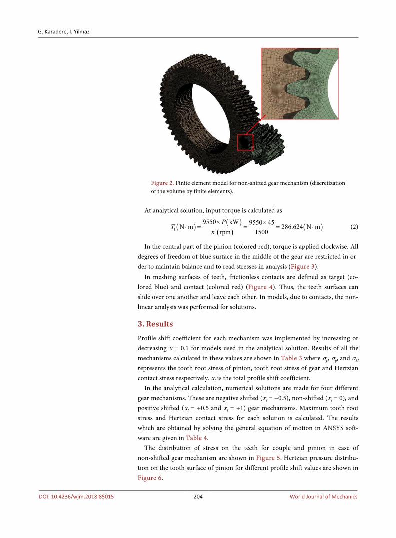
The total number of nodes for each model is over two million. The total number of elements is over five hundred thousand. The finite element model created for non-shifted gear mechanism is shown in Figure 2.
Figure 1. Influence of pinion profile shift coefficient on the pinion tooth geometry (for numerical solution).
Table 2. Grid independece study of the non-shifted case.
Edge length (mm) σp (MPa) σg (MPa)
0.25 76.41 66.56
0.5 76.57 66.08
0.75 77.81 69.79
1 79.27 77.18
2 107.78 81.35
G. Karadere, I. Yilmaz
DOI: 10.4236/wjm.2018.85015 204 World Journal of Mechanics
Figure 2. Finite element model for non-shifted gear mechanism (discretization of the volume by finite elements).
At analytical solution, input torque is calculated as
( ) ( )( ) ( )1
1
9550 kW 9550 45N m 286.624 N mrpm 1500P
Tn× ×
⋅ = = = ⋅ (2)
In the central part of the pinion (colored red), torque is applied clockwise. All degrees of freedom of blue surface in the middle of the gear are restricted in or-der to maintain balance and to read stresses in analysis (Figure 3).
In meshing surfaces of teeth, frictionless contacts are defined as target (co-lored blue) and contact (colored red) (Figure 4). Thus, the teeth surfaces can slide over one another and leave each other. In models, due to contacts, the non-linear analysis was performed for solutions.
3. Results
Profile shift coefficient for each mechanism was implemented by increasing or decreasing x = 0.1 for models used in the analytical solution. Results of all the mechanisms calculated in these values are shown in Table 3 where σp, σg, and σH represents the tooth root stress of pinion, tooth root stress of gear and Hertzian contact stress respectively. xt is the total profile shift coefficient.
In the analytical calculation, numerical solutions are made for four different gear mechanisms. These are negative shifted (xt = −0.5), non-shifted (xt = 0), and positive shifted (xt = +0.5 and xt = +1) gear mechanisms. Maximum tooth root stress and Hertzian contact stress for each solution is calculated. The results which are obtained by solving the general equation of motion in ANSYS soft-ware are given in Table 4.
The distribution of stress on the teeth for couple and pinion in case of non-shifted gear mechanism are shown in Figure 5. Hertzian pressure distribu-tion on the tooth surface of pinion for different profile shift values are shown in Figure 6.

G. Karadere, I. Yilmaz
DOI: 10.4236/wjm.2018.85015 205 World Journal of Mechanics
Figure 3. Boundary conditions.
Figure 4. Contact surfaces.
Figure 5. The distribution of von-Mises stress on the teeth for couple and pinion.

G. Karadere, I. Yilmaz
DOI: 10.4236/wjm.2018.85015 206 World Journal of Mechanics
Figure 6. Hertzian pressure distribution on the tooth surface of pinion for different profile shift values.
Table 3. Analytical solution results for profile shifted gear mechanisms.
xt xp xg σp (MPa) σg (MPa) σH (MPa)
−0.5 0.19 −0.69 86.29 92.00 555.87
−0.4 0.21 −0.61 85.34 90.10 547.55
−0.3 0.23 −0.53 83.75 86.29 540.26
−0.2 0.25 −0.45 83.12 84.07 533.95
−0.1 0.27 −0.37 82.48 81.85 527.71
0 0 0 96.76 72.97 522.50
0.1 0.31 −0.21 79.95 78.36 517.53
0.2 0.33 −0.13 79.31 77.09 512.85
0.3 0.35 −0.05 78.68 74.24 508.41
0.4 0.37 0.03 77.72 72.65 504.17
0.5 0.40 0.10 75.82 72.33 500.38
0.6 0.42 0.18 75.19 70.75 496.76
0.7 0.44 0.26 74.24 69.79 493.17
0.8 0.46 0.34 73.28 68.84 490.02
0.9 0.48 0.42 72.65 67.89 486.81
1 0.50 0.50 71.70 66.94 483.99
Table 4. Numerical solution results for profile shifted gear mechanisms.
Xt Xp Xg σp (MPa) σg (MPa) σH (MPa)
−0.5 0.19 −0.69 69.65 74.66 410.81
0 0 0 76.57 66.08 363.95
0.5 0.40 0.10 67.87 67.50 349.19
1 0.50 0.50 66.98 65.60 344.61

G. Karadere, I. Yilmaz
DOI: 10.4236/wjm.2018.85015 207 World Journal of Mechanics
The following conclusions have been reached in the analytical solution. Ac-cording to non-shifted gear mechanism, the center distance has decreased ap-proximately 0.27% for negative profile shift of each x = −0.1. According to non-shifted gear mechanism, the center distance has increased approximately 0.25% for positive profile shift of each x = +0.1.
According to non-shifted gear mechanism, the pressure angle has decreased approximately 2.24% for negative profile shift of each x = −0.1. According to non-shifted gear mechanism, the pressure angle has increased approximately 1.88% for positive profile shift of each x = +0.1.
Due to small number of teeth of the pinion, only positive profile shift is ap-plied to prevent undercut in pinion. According to non-shifted gear mechanism, the pinion tooth root stress has decreased approximately 5.44% for positive pro-file shift of each x = +0.1.
According to non-shifted gear mechanism, the gear tooth root stress has in-creased approximately 3.63% for negative profile shift of each x = −0.1. Accord-ing to non-shifted gear mechanism, the gear tooth root stress has decreased ap-proximately 1.52% for positive profile shift of each x = +0.1.
According to non-shifted gear mechanism, Hertzian contact stress has in-creased approximately 1.14% for negative profile shift of each x = −0.1. Accord-ing to non-shifted gear mechanism, Hertzian contact stress has decreased ap-proximately 0.83% for positive profile shift of each x = +0.1.
Profile shift coefficient for each mechanism was implemented by increasing or decreasing x = 0.5 for models used in the numerical solution.
Tooth root stresses and Hertzian contact stresses are increased with negative profile shift, while they are decreased with positive profile shift.
Compared to the numerical simulation results, the pinion tooth root stress has decreased approximately 3.42% for each x = +0.1 positive profile shift coeffi-cient, according to non-shifted gear mechanism.
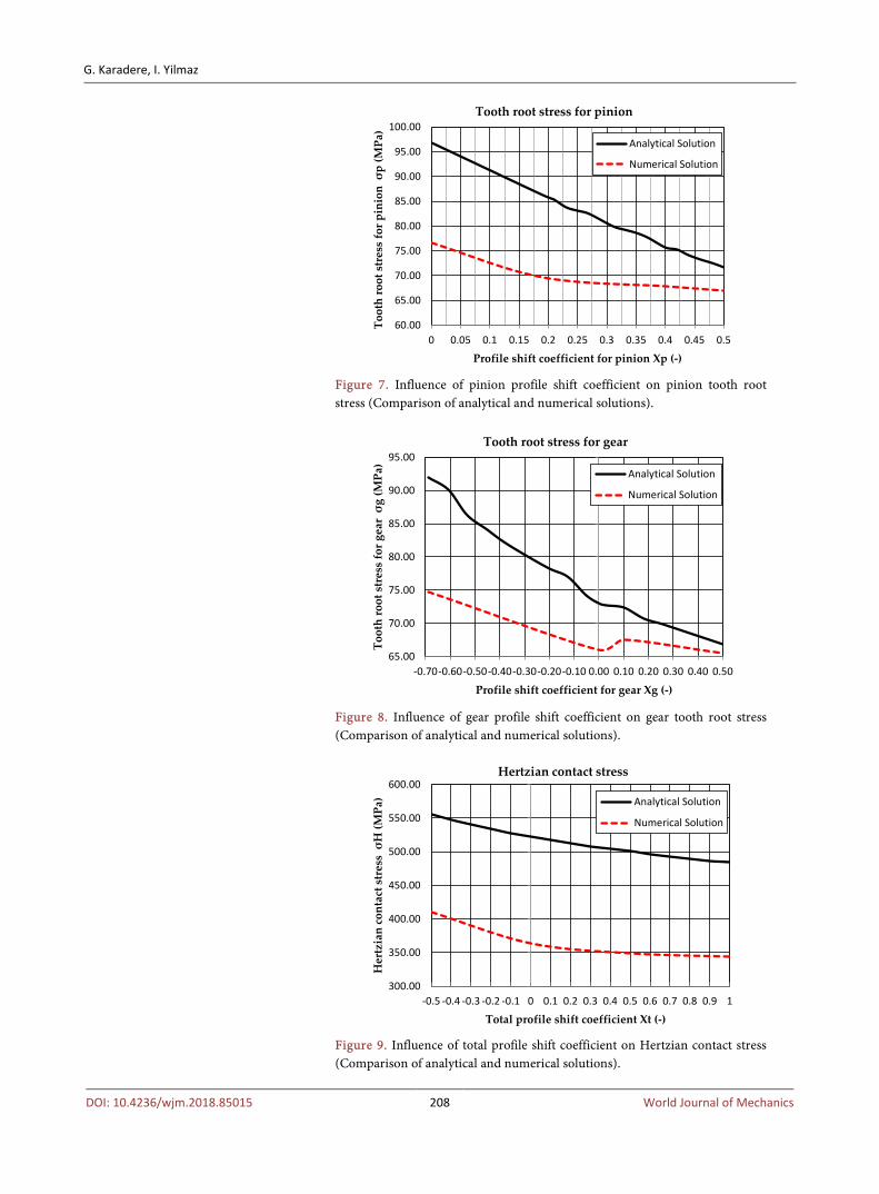
If the analytical and the numerical results are compared, the analytical results are found to be at higher values. This is because the analytical calculation is done for the most critical case. As seen from Figure 7 and Figure 8, the analyti-cal-numerical result differences from negative profile shifting towards positive profile shifting have been decreased.
While the difference for tooth root stress of non-shifted pinion is 20.72%, the difference is 6.58% for positive shifted pinion of xp = 0.5 (Figure 7). While the difference for tooth root stress of negative shifted gear of xg = −0.69 is 18.85%, the difference is 2% for positive shifted gear of xg = 0.5 (Figure 8). As seen from Figure 9, Hertzian contact stresses in the analytical solution have been decreased approximately 28% compared to numerical results.
4. Conclusion
Consequently, in this study, the results of the analytical solution, have been found to be larger according to the results of the numerical solution. The differ-ences of tooth root stresses found through analytical and numerical methods is
G. Karadere, I. Yilmaz
DOI: 10.4236/wjm.2018.85015 208 World Journal of Mechanics
Figure 7. Influence of pinion profile shift coefficient on pinion tooth root stress (Comparison of analytical and numerical solutions).
Figure 8. Influence of gear profile shift coefficient on gear tooth root stress (Comparison of analytical and numerical solutions).
Figure 9. Influence of total profile shift coefficient on Hertzian contact stress (Comparison of analytical and numerical solutions).
60.00
65.00
70.00
75.00
80.00
85.00
90.00
95.00
100.00
0 0.05 0.1 0.15 0.2 0.25 0.3 0.35 0.4 0.45 0.5
Toot
h ro
ot s
tres
s fo
r pin
ion
σp
(MPa
)Profile shift coefficient for pinion Xp (-)
Tooth root stress for pinion
Analytical Solution
Numerical Solution
65.00
70.00
75.00
80.00
85.00
90.00
95.00
-0.70-0.60-0.50-0.40-0.30-0.20-0.10 0.00 0.10 0.20 0.30 0.40 0.50
Toot
h ro
ot s
tres
s fo
r gea
r σg
(MPa
)
Profile shift coefficient for gear Xg (-)
Tooth root stress for gear
Analytical Solution
Numerical Solution
300.00
350.00
400.00
450.00
500.00
550.00
600.00
-0.5 -0.4 -0.3 -0.2 -0.1 0 0.1 0.2 0.3 0.4 0.5 0.6 0.7 0.8 0.9 1
Her
tzia
n co
ntac
t str
ess
σH
(MPa
)
Total profile shift coefficient Xt (-)
Hertzian contact stress
Analytical Solution
Numerical Solution

G. Karadere, I. Yilmaz
DOI: 10.4236/wjm.2018.85015 209 World Journal of Mechanics
gradually decreased in the direction of a positive shift. Hertzian contact stress differences between the two solutions, have been remained almost the same. However, the differences are much greater compared to the tooth root stresses. The effect of profile shifting on tooth root stresses, is larger than in Hertzian contact stresses. The effect of negative profile shifting on especially tooth root stresses, is larger than in positive profile shifting. Selecting the appropriate pro-file shift coefficients, the fatigue strength and service life of gears can be in-creased as mentioned in the references. Similarly, vibrations and noise can be reduced. Similar theoretical studies/practical research results such as this article will guide the designer in design decisions process.
References [1] Hamrock, B.J., Schmid, S.R. and Jacobson, B.O. (2006) Fundamentals of Machine
Elements. McGraw-Hill Education, New York, 673-674.
[2] Maitra, G.M. (2008) Handbook of Gear Design. McGraw-Hill Education, New Del-hi, 11-12.
[3] Shigley, J.E. and Mischke, C.R. (1996) Machine Design. McGraw-Hill Education, New York.
[4] Antal, T.A., Antal, A. and Arghir, M. (2008) Determination of the Addendum Mod-ification at Helical Gears, at the Points Where the Meshing Starts and Ends, Based on the Relative Velocity Equalization Criterion. 79th Annual Meeting of the Inter-national Association of Applied Mathematics and Mechanics (GAMM), Bremen, December 2008, 10965-10966. https://doi.org/10.1002/pamm.200810965
[5] Senthil Kumar, V., Muni, D.V. and Muthuveerappan, G. (2008) Optimization of Asymmetric Spur Gear Drives to Improve the Bending Load Capacity. Mechanism and Machine Theory, 43, 829-858. https://doi.org/10.1016/j.mechmachtheory.2007.06.006
[6] Mallesh, G., Math, V.B., Ashwij, Dutt, R.P.S. and Shanbhag, R. (2009) Effect of Tooth Profile Modification in Asymmetric Spur Gear Tooth Bending Stress by Fi-nite Element Analysis. 14th National Conference on Machines and Mechanisms (NaCoMM09), Durgapur, 17-18 December 2009, 62-67.
[7] Magalhaes, L., Martins, R., Locateli, C. and Seabra, J. (2010) Influence of Tooth Pro-file and Oil Formulation on Gear Power Loss. Tribology International, 43, 1861-1871. https://doi.org/10.1016/j.triboint.2009.10.001
[8] Baglioni, S., Cianetti, F. and Landi, L. (2012) Influence of the Addendum Modifica-tion on Spur Gear Efficiency. Mechanism and Machine Theory, 49, 216-233. https://doi.org/10.1016/j.mechmachtheory.2011.10.007
[9] Li, X., Jiang, S. and Zeng, Q. (2013) Optimal Selection of Addendum Modification Coefficients of Involute Cylindrical Gears. Journal of Computers, 8 2156-2161. https://doi.org/10.4304/jcp.8.8.2156-2161
[10] Yilmaz, I. (2013) Investigation of the Effect of Profile Shifting in Helical Gear Me-chanisms with Analytical and Numerical Methods. M.Sc. Thesis, Graduate School of Natural and Applied Science, Uludag University, Bursa. (In Turkish)
[11] German Institute for Standardization (1964) Addendum Modification of External Spur and Helical Gears (DIN 3992). Berlin.
[12] Mackerle, J. (1999) Finite Element Analysis of Machine Elements: A Bibliography (1977-1997). Engineering Computations, 16, 677-748. https://doi.org/10.1108/02644409910286429