investigation of the opportunity for heat integration at...
TRANSCRIPT

chalmers university of technologyse 412 96 Gothenburg, SwedenPhone: + 46 - (0)31 772 10 00Web: www.chalmers.se
Investigation of the opportunity for
heat integration at Preemraff Göteborg
Master’s Thesis within the Innovative and Sustainable Chemical Engineering programme
ROBIN GOTTFRIDSSON & ISABELLE JOHANSSON Department of Energy and Environment Division of Heat and Power Technology CHALMERS UNIVERSITY OF TECHNOLOGY Göteborg, Sweden 2011

MASTER’S THESIS
Investigation of the opportunity for
heat integration at Preemraff Göteborg
Master’s Thesis within the Innovative and Sustainable Chemical Engineering programme
ROBIN GOTTFRIDSSON & ISABELLE JOHANSSON
SUPERVISORS:
Viktor Andersson
Cecilia Hellman
Sofia Ohlsson
EXAMINER
Thore Berntsson
Department of Energy and Environment Division of Heat and Power Technology
CHALMERS UNIVERSITY OF TECHNOLOGY
Göteborg, Sweden 2011

Investigation of the opportunity for heat integration at Preemraff Göteborg Master’s Thesis within the Innovative and Sustainable Chemical Engineering programme ROBIN GOTTFRIDSSON & ISABELLE JOHANSSON
© ROBIN GOTTFRIDSSON, ISABELLE JOHANSSON, 2011
Department of Energy and Environment Division of Heat and Power Technology Chalmers University of Technology SE-412 96 Göteborg Sweden Telephone: + 46 (0)31-772 1000 Cover: Picture showing air-cooled exchangers in the crude distillation unit. To the right are four heat exchangers connected to the district heating system. Chalmers Reproservice Göteborg, Sweden 2011

I
Investigation of the opportunity for heat integration at Preemraff Göteborg Master’s Thesis in the Innovative and Sustainable Chemical Engineering programme ROBIN GOTTFRIDSSON & ISABELLE JOHANSSON Department of Energy and Environment Division of Heat and Power Technology Chalmers University of Technology
ABSTRACT
The industrial society is a large contributor to the anthropogenic climate change. It is therefore crucial to decrease the use of fossil fuels and to find better and more sustainable alternatives that are economically feasible. When price of energy and carbon credits increases due to limited reserves and environmental issues, the significance for improving energy efficiency becomes more important. For an energy demanding industry like oil refining, the incentives to decrease energy consumption is large in order to keep down the running costs. Pinch analysis is than a helpful tool for identifying potential energy savings at an existing plant.
In this master thesis, a pinch analysis has been performed at Preemraff Göteborg with the objective to investigate the option for increased internal heat recovery, thereby decreasing the utility demand. The potential for energy savings has been evaluated using information and stream-data collected at the refinery.
The pinch analysis shows that Preemraff Göteborg has a theoretical potential to save 40,2 MW of hot and 47,8 MW of cold utility. A retrofit replacing 12,9 MW of hot and 10,9 MW of cold utility, out of which 3,1 MW is reduction of deliveries to the district heating system, has been identified. The proposed heat exchanger network consists of 10 heat exchangers, and the cost was estimated to 28,5 MSEK with a payback time of 0,48 year. The retrofit also corresponds to approximately 25 kton of decreasing CO2 emissions annually.
Key words: Pinch analysis, retrofit, energy savings, oil refinery

II
En utredning över möjligheten för ökad värmeintegrering på Preemraff Göteborg Examensarbete inom masterprogrammet Innovative and Sustainable Chemical Engineering ROBIN GOTTFRIDSSON & ISABELLE JOHANSSON Institutionen för Energi och Miljö Avdelningen för Värmeteknik och maskinlära Chalmers Tekniska Högskola
SAMMANFATTNING
Industrisektorn är en stor källa till de antropogena utsläpp som orsakar global klimatförändring. Det är därför viktigt att minska användandet av fossila bränslen och finna bättre och mer miljövänliga alternativ som är ekonomiskt hållbara. Med ökande priser på bränsle och utsläppsrätter på grund av begränsade energitillgångar blir energieffektiviseringar allt viktigare. Detta blir extra viktigt för energiintensiva industrier som oljeraffinaderier där bränslekostnader är en stor utgift. Pinchanalys är då ett kraftfullt och hjälpfullt verktyg för att identifiera potentiella energibesparingar inom en befintlig anläggning.
I detta examensarbete har en pinchanalys utförts vid Preemraff Göteborg med målet att undersöka möjligheten för en ökad intern värmeåtervinning, och därmed minska behovet av befintliga hjälpsystem. Med hjälp av tillgänglig information och insamlad data från Preemraff Göteborg har potentialen för en ökad energibesparing undersökts.
Pinchanalysen visar att det är teoretiskt möjligt att minska värmetillförseln med 40,2 MW och kylbehovet med 47,8 MW. Ett förslag till ombyggnad som ersätter 12,9 MW varma och 10,9 MW kalla hjälpsystem, varav 3,1 MW består av minskade fjärrvärmeleveranser, har presenterats. Det föreslagna värmeväxlarnätverket består av 10 värmeväxlare och kostnaden för detta uppgår till 28,5 MSEK med en återbetalningsperiod på 0,48 år. Förslaget motsvarar också en årlig minskning av CO2-utsläpp med cirka 25 kton.
Nyckelord: Pinchanalys, ombyggnation, energieffektivisering, oljeraffinaderi
III
Contents
ABSTRACT I
SAMMANFATTNING II
CONTENTS III
PREFACE V
NOTATIONS VI
1 INTRODUCTION 1
1.1 Objective 2
1.2 Problem analysis 2
1.3 Method 2
1.4 Limitations 2
2 PINCH ANALYSIS 5
2.1 Theory 5
2.2 Retrofitting a heat exchanger network 8
2.2.1 Matrix method 9
2.3 ProPi 10
3 PREEM REFINERY 11
3.1 The process 11
3.2 Energy 12
3.2.1 District heating 13
3.2.2 Utilities 13
4 METHODOLOGY 15
4.1 Data collection 15
4.2 Evaluation of the data 15
4.2.1 Stream representation 16
4.3 Economical aspects 16
4.4 The Matrix method 18
5 PRESENT SITUATION 19
5.1 Composite curves 19
IV
6 RETROFIT SUGGESTION 23
6.1 Retrofit proposal 24
6.1.1 Pinch violations 27
6.1.2 Economy 27
6.2 Emission savings 29
6.3 District heating 30
7 DISCUSSION 31
7.1 Retrofit 31
7.2 The district heating system 33
7.3 Economy 34
8 CONCLUSIONS 35
9 FURTHER WORK 37
10 REFERENCES 39
11 APPENDIX 1 – STREAM DATA 41
12 APPENDIX 2 – HEAT TRANSFER COEFFICIENT 45
13 APPENDIX 3 – MATRIX WITH DUTY ABOVE THE PINCH 47
14 APPENDIX 4 – MATRIX WITH DUTY BELOW THE PINCH 49
15 APPENDIX 5 – EMISSIONS FOR A CAR 51

V
Preface
In this master’s thesis Preemraff Göteborg has been studied using pinch analysis. The objective has been to investigate the opportunity to decrease the energy consumption by replacing utilities with internal heat exchangers. The work has been carried out at the Division of Heat and Power at Chalmers University of Technology in cooperation with Preemraff Göteborg and COWI.
We would like to express our gratitude to our supervisors Cecilia Hellman at Preemraff, Viktor Andersson at Chalmers and Sofia Ohlsson at COWI for all helpful inputs and support. We would also like to thank the process engineers at Preemraff Göteborg for much valued help during this project.
Göteborg, June 2011
Robin Gottfridsson and Isabelle Johansson

VI
Notations
A Heat exchanger area [m2] CC Composite Curve Cp Specific heat capacity [J/kg K] F Flow rate [Sm3/d, Nm3/h] GCC Grand Composite Curve HP High pressure steam, 15 barg HX Heat exchanger h hour h1 Heat transfer coefficient for stream 1 [kW/(m2K)] h2 Heat transfer coefficient for stream 2 [kW/(m2K)] J Joule kW kilowatt LP Low pressure steam, 3,5 barg MER Maximum energy recovery MK1 Diesel with environmental classification 1, containing low sulphur MWh Megawatt hour PBP Payback period [yr] Q Heat duty [W] RME Rapeseed Methyl Esther U Overall heat transfer coefficient [kW/(m2K)] ∆TC Temperature difference on cold side [K] ∆TH Temperature difference on hot side [K]
∆Tlm Logarithmic mean temperature difference [K] ∆Tmin Minimum temperature difference [K]

1
1 Introduction
In today’s energy-consuming society it is important, from both an economical and an environmental aspect, to decrease the energy demand and to find more sustainable solutions for providing the required energy. As fuel and electricity prices rise, using energy more efficient is of growing importance. To reach a more sustainable future worldwide, the EU adopted a new energy and climate policy in 2008 which includes targets for the year 2020, the so called “20/20/20”-package. It involves 20% reduction of greenhouse gases based on the levels in 1990, 20% reduction of energy consumption through energy efficiency and that 20% of the energy supply should come from renewable sources1. [2]
Refining oil is an energy-intense process. In 2009, the fuel consumption and electricity demand at Preemraff Göteborg was 2570 GWh and 150 GWh respectively. [3] If this is compared to 25 MWh, the energy consumption in a Swedish normal household in a year, Preemraff Göteborg corresponds to 110 000 normal households. [4] The refinery is situated at Hisingen and has a capacity of refining 6 million ton crude oil every year. [5]
Preemraff Göteborg is working hard to decrease their environmental impact. One example is the newly developed bio refinery unit producing bio diesel from tall oil for mixing with fossil diesel, which was built in 2010. [1] They also mix renewable components such as RME2 and ethanol with diesel and gasoline and drive the question to increase the maximum allowed levels of these additives. In the latest study from Solomon Associates, a consulting company that performs a bench marketing study of participating refineries every second year, Preem was ranked in the top compared to other refineries in Europe. It shows that Preem emits 25% less CO2, 70% less NOx and 95% less SO2 compared to an average refinery in Western Europe. [1] A reason for this is the opportunity to deliver district heating. This is due to that the refinery produces a lot of heat at temperatures which are to low to be used at most places in the process. Instead of cooling to the surroundings Preemraff heats the district heating system with it.
This excess heat is delivered to Göteborg Energi AB, GEAB, via two separate systems, one going straight to Volvo Torslanda and one connected to the municipal district heating system. During the cold seasons, when demand for district heating is high, the refinery’s cooling demand is met mainly by the district heating system but during summer excess heat must be removed by air fans. It is desirable to instead make use of the excess heat internally in the process and thereby minimize the fuel consumption and the need for cooling during summer.
1 For Sweden this means that 50 % of all energy will come from renewable sources by 2020. [1] 2 Rapeseed Methyl Esther

2
1.1 Objective
The aim of this master thesis is to investigate the opportunity for an increased use of internal heat exchanging at Preemraff Göteborg using pinch analysis. Investigation of the refinery’s energy consumption and current system will result in a retrofit proposal that increases internal heat recovery, thereby decreasing the fuel consumption and the resulting emissions. It is also desirable to compare today´s energy consumption and the minimum energy needed if the studied system was constructed as a MER3 network.
1.2 Problem analysis
To simplify the data collection as much as possible it is important to first identify a system boundary. This because the data collection is a very large and time consuming part that can easily slow down the work if there is no clear structure. The studied system, further explained and limited in 1.4 Limitations includes streams heated or cooled using utilities at all units of the refinery. To be able to calculate the individual duty for all streams density, flow, start and target temperature and specific heat capacity or enthalpy have been extracted.
1.3 Method
The project consists of three main parts; literature study, data collection and an evaluation of the data.
The literature study will focus on oil refining in general and at Preemraff Göteborg in particular. Pinch technology will also be studied more closely. The second part includes collection of all necessary data and is the most time consuming part. This information is used to identify misuse of utilities and streams with a potential for heat exchanging.
In the third part of the project the data is analysed using pinch analysis. Streams suitable for heat exchanging are identified and a rough economical estimation, for the suggested retrofit, is performed.
1.4 Limitations
To be able to perform this master thesis within 20 weeks a complete pinch study including all streams at the refinery will not be performed. Instead the system boundaries are set so that only streams heated or cooled with utilities such as steam, furnaces, air cooling and district heating are included. This means that all process streams currently heat exchanged with other process streams are rejected. Apart from streams using utilities some streams not presently used for heating or cooling will be included. These are mainly effluent flue gases where further cooling is possible and cold feed of combustion air into furnaces with the potential for preheating.
3 Maximum Energy Recovery

3
The data, and therefore, the pinch analysis will be valid for a summer case when the need for cooling is at its highest. During the winter, cooling is performed by the district heating system and air coolers combined, but during the summer air coolers are used to a larger extent since the demand for district heating is low.
Apart from air cooling and cooling through the district heating system there is a cooling water system at Preemraff. It has been decided, in discussion with Preemraff Göteborg, not to include this system due to seasonal intermittence and lack of data. The cooling water system is small compared to the other cold utilities included in the analysis. Note that the district heating system and the cooling water system are two separate systems.

4

2 Pinch analysis
Pinch analysis was developed at the Manchester in the late 1970systematically determining the minimum heating and cooling demand of a process and a tool for optimizing the energy recovery and thereby minimizing the need for hot and cold utilities. Pinch analysis is a useful tool when performing energy analysis on both existing industrial plants and for grass rot designsand money. [6]
2.1 Theory
This chapter only covers pinch analysis briefly.book: Pinch Analysis and Processsection is originally from.
When starting to use pinch analysis identified as a hot or cold stream. A hot stream is, regardless of its temperature, a stream which requires cooling and a cold stream is forrequiring heating. Each stream has a start and target
By combining all the individual loads the hot streams it is possible to produce a hot Composite Curve, CCfor the cold streams produces the cold composite curve.can be seen as a summation of all individual hot and cold streams.plotted in a temperature/enthalpyenergy demand can be drawn.
Figure 1. Hot and cold composite curveand the thin line the cold composite curve.
The different streams in the composite curves have different slopes since the slope corresponds to the product of flow and specific heat. It is preferable to use the
5
Pinch analysis
Pinch analysis was developed at the Institute of Science and TechnologyManchester in the late 1970s by Professor Bodo Linhoff. It is a methodologysystematically determining the minimum heating and cooling demand of a process
ng the energy recovery and thereby minimizing the need for hot Pinch analysis is a useful tool when performing energy analysis on
both existing industrial plants and for grass rot designs, in order to save both energy
covers pinch analysis briefly. For further information refer to Pinch Analysis and Process Integration where most of the information in this
[7]
When starting to use pinch analysis all streams requiring heating or coolinghot or cold stream. A hot stream is, regardless of its temperature, a
ooling and a cold stream is for the same reason a stream requiring heating. Each stream has a start and target temperature as well as a duty.
the individual loads and the corresponding temperature intervalsit is possible to produce a hot Composite Curve, CC. Doing the same
for the cold streams produces the cold composite curve. The two composite curves can be seen as a summation of all individual hot and cold streams. If these curves are plotted in a temperature/enthalpy-diagram valuable information about theenergy demand can be drawn. See Figure 1 for an example of composite curves.
. Hot and cold composite curve. Bold line represents the hot composite curve
and the thin line the cold composite curve.
The different streams in the composite curves have different slopes since the slope corresponds to the product of flow and specific heat. It is preferable to use the
Institute of Science and Technology in is a methodology to
systematically determining the minimum heating and cooling demand of a process ng the energy recovery and thereby minimizing the need for hot
Pinch analysis is a useful tool when performing energy analysis on in order to save both energy
For further information refer to the where most of the information in this
requiring heating or cooling must be hot or cold stream. A hot stream is, regardless of its temperature, a
the same reason a stream as well as a duty.
temperature intervals of Doing the same
The two composite curves If these curves are
valuable information about the systems for an example of composite curves.
. Bold line represents the hot composite curve
The different streams in the composite curves have different slopes since the slope corresponds to the product of flow and specific heat. It is preferable to use the

6
available heat from the hot stream as much as possible. As seen in Figure 1 the maximum possible energy recovery is the area where the hot and cold composite curves overlap. As long as the hot composite curve, (which needs cooling) has a higher temperature than the cold composite curve it is possible to recover energy by internal heat exchanging. Also shown in the figure is the minimum hot and cold utility demand which is the need for external heating and cooling if maximum energy is recovered. A network which meets this target of maximum energy recovery and thereby minimizing the need for external utility use is called a Maximum Energy Recovery, MER, network.
The shortest distance between the two composite curves is called the pinch. The temperature where the pinch is situated is therefore called the pinch temperature. The temperature difference between the hot and cold composite curves at the pinch is called the minimum temperature difference, (∆Tmin), and represents the lowest acceptable temperature difference between the hot and the cold streams in a heat exchanger. The minimum temperature difference is free to choose but is usually in the region of 10-20 K. One can select an individual ∆Tmin in all heat exchangers or use a global value throughout the process. The temperature difference has however significant impact on the heat exchanger cost, remembering that:
� � � � ΔTlm 1�
Where Q= Duty [W] A= Area [m2] ∆Tlm = Logarithmic mean temperature difference [ K] U= Overall heat transfer coefficient [W/m2K]
As seen the temperature difference is inverse proportional to the size of the heat exchanger required between two streams. With a large temperature difference between two heat exchanging streams the driving force will be large and consequently the heat exchanging area decreases, whilst the need for external utility increases. This can be seen in the above figure since with a larger ∆Tmin the cold composite curve must be shifted to the right causing internal energy recovery to decrease and thereby external utility need to increase. Because of this, choosing ∆Tmin is important since it is correlated to operating cost and investment cost.
The pinch temperature divides the system into two thermodynamically separate systems. The system acting above the pinch temperature will have a heating demand and the system acting below the pinch will have a cooling demand. Hot streams above the pinch temperature can be used to heat the cold streams above the pinch. The cold streams below the pinch can be heated using the hot streams below the pinch. Deviations from a MER network, resulting in increased demand of utilities, can be explained by violations to the three pinch rules:
• Do not use coolers above the pinch • Do not use heaters below the pinch • Do not transfer heat through the pinch

7
Figure 2: Illustration of the three pinch rules. [22]
As seen in the figure above, breaking these rules will result in a heating and cooling demand that is higher than the minimum possible. Cooling above the pinch, where heat is needed, will result in a larger heating demand above the pinch. Heating below the pinch, where there is a heat surplus, will for the same reasons result in an increased cooling demand. Transferring heat through the pinch will lead to a higher utility demand on both sides of the pinch, since removing heat from above the pinch results in a higher hot utility demand and adding heat below the pinch will result in a larger need for cooling. Instead internal heat exchanging above and below the pinch should be used to ensure that no energy is wasted.
When performing a pinch analysis it is convenient to work with so called interval temperatures. The interval temperature is calculated by subtracting ∆Tmin/2 from all hot streams and adding ∆Tmin/2 to all cold streams. By plotting the net heat flow against the shifted temperatures a Grand Composite Curve, GCC, can be created as seen in Figure 3. This represents the net heat flow to the interval temperatures. From this it is possible to see not only the minimum amount of cooling and heating necessary to run the process but also at what temperatures this heating and cooling demand must operate, which is a large benefit. Another advantage of this GCC is that it can be used for studying different potential for heat integration and use of waste heat.

8
Figure 3. Grand composite curve showing the minimum hot and cold utility demand
The minimum heating and cooling demand of the process are easily read of from the GCC above. A so-called “pocket” can also be seen in the GCC and represent a region where the cold stream is not in need of external heating using utility, since it can be heat exchanged with a hot process stream within the process. The pinch temperature is found where the GCC touches the temperature axis and divides the process in the two networks above and below the pinch. It is important to note that a change in ∆Tmin can have a drastic effect on the shape of the GCC and thereby also the pinch temperature, since a change in ∆Tmin changes the need for external heating and cooling supplied by utility.
As mentioned before, a MER network can be created if all energy possible to recover is recovered. This implies that all heat exchangers are placed according to the pinch rules so that no pinch violation is present. The MER network will have the same heating and cooling demand as the one shown in the GCC. It is however not economically feasible to construct all heat exchangers recommended in the MER network. That would require building a heat exchanger network with unreasonable large heat exchanger area, numerous small heat exchangers and large piping distance.
2.2 Retrofitting a heat exchanger network
Rebuilding an existing plant to follow all pinch rules requires extensive reconstructions which is often costly. A better alternative is to do a retrofit. When using pinch analysis to modify an existing process, the energy demand can be decreased in an economically feasible way. The goal when retrofitting is never to construct a maximum energy recovery network. Built-in constraints, lack of space and economical issues are limiting the options of possible heat recovery as the investment cost increases with increasing internal heat recovery.
The basic principle when retrofitting a heat exchanger network is to retrain existing heat exchangers in their original positions as far as possible. Existing heat exchangers have already been invested in and although they might not be perfectly fitted in the network it would not be economically feasible to replace all of them. Instead

9
modification of some of them can be done in order to make them fit in the new process. Of course some new heat exchangers must be invested in. It is also preferable to re-pipe as little as possible since piping is expensive and might require other changes in the process. In a proposed heat exchanger network it will always be a compromise between energy savings and economy.
The goal is to make economically sustainable and effective heat exchangers that follow the pinch rules and also to eliminate current pinch violations as much as possible.
2.2.1 Matrix method
When performing a retrofit it is important to include as many streams as possible to keep all opportunities open and not exclude streams because one may think that it is unnecessary due to temperature, location etc. All this should be left to the pinch analysis. The way to find the best retrofit design can be a very complex and iterative process since it includes a lot of different choices when it comes to heat exchanger alternatives.
The Matrix method, developed at the division of Heat and Power Technology at Chalmers, is a strategy for retrofitting heat exchanger networks and to identify energy-saving and economically feasible heat exchanging possibilities. It is well suited to handle a large number of possible heat exchanger alternatives and the economic aspects. Instead of only looking at the cost for the new heat exchanger area which in most cases only refers to one part of the total cost of the retrofit, the Matrix method also takes parameters as piping costs, maintenance costs and costs associated with pressure drop into account. The area costs are easily calculated compared to the piping and maintenance costs that must be approximated with the site in mind as they are dependent of distance, type of material and space respectively. [8] To simplify the analysis only investment costs based on the heat exchanger area and piping costs are considered in this thesis.
The base in the Matrix method is two matrices, one above and one below the pinch, containing all heat exchanger possibilities and the resulting cost. In both matrices rows correspond to hot streams and columns correspond to cold streams. When dividing all streams into these two matrices, pinch violations due to existing heat exchangers are taken into account and often the pinch rule has to be omitted. This results in some pinch violations that are considered acceptable, since it is not economically feasible to for example, install two new heat exchangers, one operating above and one below the pinch instead of using the already existing one operating to some extent through the pinch.
The construction of the network is an iterative process where the cheapest heat exchanger is placed first. An existing heat exchanger has low or none cost whereas a new one has a higher cost. After heat exchangers are placed between all possible streams the Matrix is recalculated for the new setup and placing of heat exchangers continue until all streams have reached their target temperature. It is possible when selecting a cheap heat exchanger first that one may end up with a really expensive one in the end, so it is important to look out for these effects and test different paths. When heat exchanging between two streams no longer is possible the remaining duty must be met by utility.

10
2.3 ProPi
Propi is an add-in in Excel developed by CIT Industriell Energy AB and is a helpful tool when working with pinch analysis. [8] By having a start and target temperature as well as the duty for all streams as input data, graphs of CC and GCC can easily be constructed showing the minimum hot and cold utility and naturally the pinch temperature. It is also possible to construct a heat exchanger network and locate pinch violations in existing networks.
11
3 Preem refinery
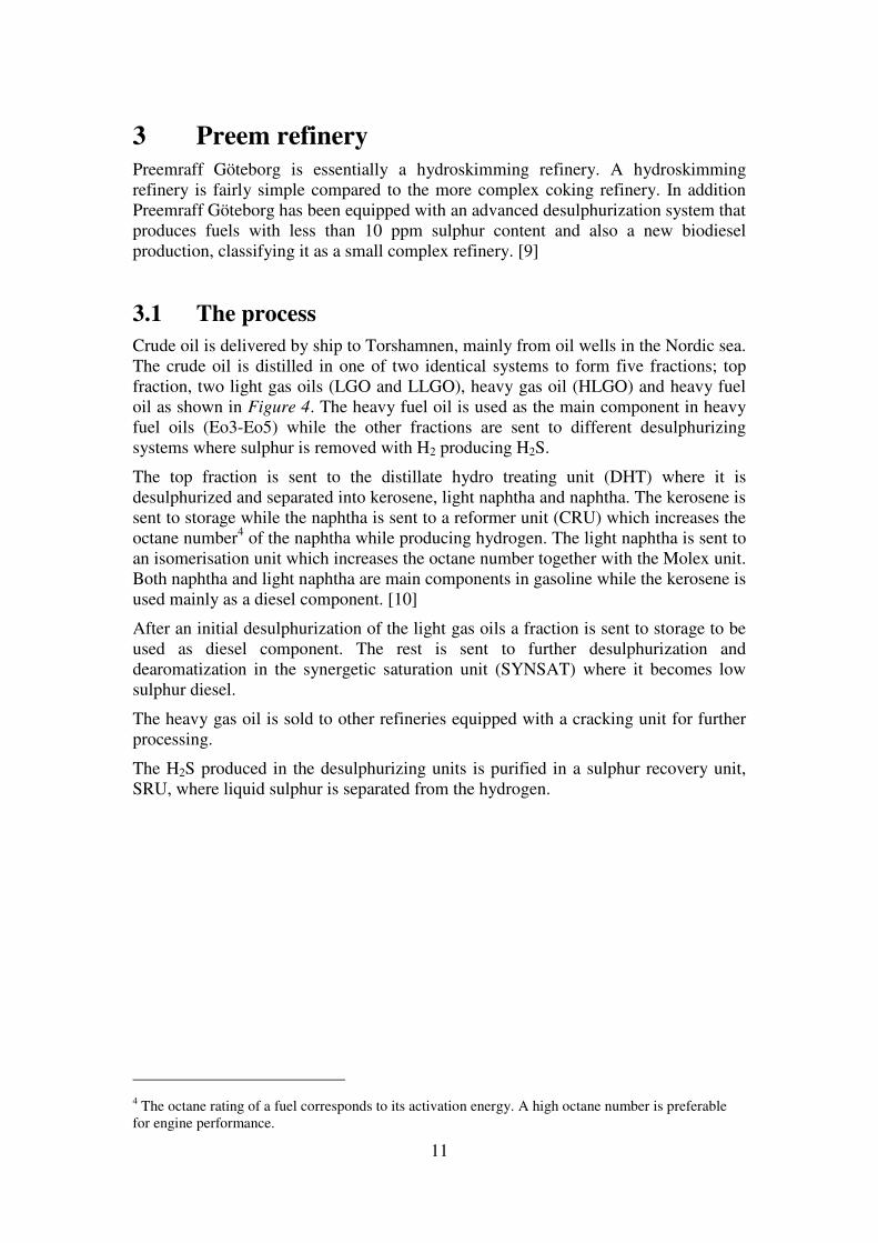
Preemraff Göteborg is essentially a hydroskimming refinery. A hydroskimming refinery is fairly simple compared to the more complex coking refinery. In addition Preemraff Göteborg has been equipped with an advanced desulphurization system that produces fuels with less than 10 ppm sulphur content and also a new biodiesel production, classifying it as a small complex refinery. [9]
3.1 The process
Crude oil is delivered by ship to Torshamnen, mainly from oil wells in the Nordic sea. The crude oil is distilled in one of two identical systems to form five fractions; top fraction, two light gas oils (LGO and LLGO), heavy gas oil (HLGO) and heavy fuel oil as shown in Figure 4. The heavy fuel oil is used as the main component in heavy fuel oils (Eo3-Eo5) while the other fractions are sent to different desulphurizing systems where sulphur is removed with H2 producing H2S.
The top fraction is sent to the distillate hydro treating unit (DHT) where it is desulphurized and separated into kerosene, light naphtha and naphtha. The kerosene is sent to storage while the naphtha is sent to a reformer unit (CRU) which increases the octane number4 of the naphtha while producing hydrogen. The light naphtha is sent to an isomerisation unit which increases the octane number together with the Molex unit. Both naphtha and light naphtha are main components in gasoline while the kerosene is used mainly as a diesel component. [10]
After an initial desulphurization of the light gas oils a fraction is sent to storage to be used as diesel component. The rest is sent to further desulphurization and dearomatization in the synergetic saturation unit (SYNSAT) where it becomes low sulphur diesel.
The heavy gas oil is sold to other refineries equipped with a cracking unit for further processing.
The H2S produced in the desulphurizing units is purified in a sulphur recovery unit, SRU, where liquid sulphur is separated from the hydrogen.
4 The octane rating of a fuel corresponds to its activation energy. A high octane number is preferable for engine performance.

12
Figure 4: Schematic figure of the process.
3.2 Energy
The energy demand of the refinery is provided by fuel gas and fuel oil produced on site and imported natural gas as a complement. The fuel gas consists of the non-condensable gases ethane, methane and hydrogen but butane and propane are also used. An excess of fuel gas can arise if problem occurs in one of the units, and in that case the fuel gas is lead to the flare. [11]
Earlier Preemraff had a gas turbine to generate electricity on site, but since it broke down in 2004 all electricity is imported. [11] In 2009, the refinery used 2566 GWh of energy. Most of this was used to heat streams and produce steam. 152 GWh was electricity mainly used to drive equipment like compressors and pumps. [12]
Both HP and LP steam is produced on site in steam boilers and are explained further in 3.2.2 Utilities. When the process at Preemraff is running on its maximum on all units the total demand of steam is approximately 110 ton/h. During the cold seasons the demand is increased with 10-15 ton/h to heat tanks and pipes. [11] The largest consumers of HP steam are the reboiler to the benzene tower in the reformer unit, a reboiler and a preheating exchanger within the isomerisation unit (ISOM) and steam turbines for running pumps. For the LP consumers the large units are Molex, crude oil units, Amin, LPG, tanks and pipes. [11]
There are several furnaces and steam boilers on Preemraff Göteborg. They mainly use gaseous fuels although some of them can be powered with fuel oil. The two furnaces preheating the crude oil, before distillation, are the largest in terms of effect.

13
3.2.1 District heating
Gothenburg has a well developed district heating system that delivers approximately 3800 GWh of heat every year. The heat is mainly produced by Sävenäs CHP-plant, Rya CHP-plant and excess heat from industries. Preemraff Göteborg is only a small contributor; approximately 7 % (310 GWh) of the heat supplied by GEAB comes from Preemraff. [3, 13]
There is also a separate district heating system for Volvo Torslanda. Preem delivers approximately 140 GWh to Volvo with peaks in winter. [3] The heat to Volvo is delivered at 130-140 °C compared to 90 °C for the GEAB system. The reason for this is that Volvo, unlike GEAB, is not only using the heat for heating buildings but also in the process. The two district heating systems at Preemraff are working independently but there is a possibility to transfer heat from one system to the other. Both systems are constructed in the same way and consist of a number of parallel circuits that pick up heat in different heat exchangers and economizers at different temperature levels throughout the process. A large amount of the heat delivered to Volvo comes from cooling the residue and HGO5 from the crude distillate towers. The heat to GEAB is transferred from all over the plant. [14]
The district heating system’s need for heat varies over the year. During the summer when the district heating demand is low Preemraff Göteborg remove their excess heat by air fans and to some degree by cooling towards GEAB’s system.
3.2.2 Utilities
The utilities used at Preemraff Göteborg are:
• Steam • District heating • Air coolers • Furnaces • Cooling water • Steam generators
Steam is mainly produced in 4 steam boilers as high and low pressure steam at 15 and 3,5 barg respectively. Preemraff has a capacity to produce 136 ton/h of HP steam and 33 ton/h of LP steam [11]. The steam is mainly used in reboilers to evaporate hydrocarbons being distilled. District heating is used both as a cold and a hot utility since it is used for cooling high temperature hydrocarbon streams but also to preheat air into one crude furnace and to heat raw water going to the deionization unit. Air is used both as the cooling media in air-cooled exchangers and as a safety system. The air coolers consist of finned tubes containing the hot streams and a fan used to increase heat transfer to the air. The air-cooled exchangers are often used as a complement to the district heating coolers, either as a replacement when the need for district heating is low, or to cool streams further down in temperature.
5 Heavy Gas Oil

14
Furnaces are used to heat streams to temperatures where steam cannot be used. The furnaces are powered mainly by fuel gas. The fuel gas mainly consists of non condensable gases from the process and includes methane and ethane. Other gases produced on site are also used and among them are propane, butane and hydrogen. The hydrogen is used for the desulphurization processes as described in 3.1 The process. Imported natural gas covers the remaining fuel gas demand and is considered as the margin fuel. [11]
Steam generators are used for cooling streams of high temperatures and produce steam. They are fed with low pressure steam condensate which is evaporated by the process streams to produce low pressure steam.

15
4 Methodology
Much of the work in this master thesis has been to study the plant and collect all the necessary data to analyze the existing situation at the plant. All data collection was carried out at Preemraff Göteborg, mostly using the program Aspen Process Explorer that stores all continuously measured data.
4.1 Data collection
Data was collected for process streams heated or cooled with utilities. A summer case with MK16 production was studied since the process runs slower when producing MK1 diesel creating a smaller load of excess energy as compared to MK3 that runs faster and thereby creates more excess energy. Since Preemraff is turning more and more towards producing MK1 diesel it is reasonable to only look at this mode. The studied periods were 16/6 – 28/6, 15/7 – 1/8 and 10/8 – 19/8 in 2010 because at these times MK1 production was stable for longer periods of times.
Most data were retrieved from online sensors via Aspen Process Explorer. Parameters such as temperature, flow and duty were taken as a mean over the period in question. If the variation of the value was large, a reasonable average was taken with help from the process operator and process engineers at Preemraff Göteborg. Apart from this, intermittent data and disabled streams could be identified.
In some cases data was not found since no measurements existed or it was not possible to calculate it through heat- and mass balances. In these cases data was taken as estimations from process engineers at site. No measurements were done in the plant since this would have given misleading information as the data collection took place during the winter when the heat profile is different. With a limited time schedule in mind these measurements would also have taken too much time.
Heat capacity, enthalpies, density and, in some cases, degree of condensation was collected from simulations in PROII, a process simulation program used at Preemraff. Data has been extracted from previously made simulations to save time. By modifying an already existing stream in PROII to correspond to the actual temperature in the studied period, it was possible to recover the necessary data. For streams undergoing phase change, the heat of vaporisation and the temperature at which it occurs was extracted. For cases where there is a phase change occurring over several temperatures a mean temperature over the interval has been used.
4.2 Evaluation of the data
All values such as flow and temperature were taken for the process side of the utility units in order to calculate the loads, except for the district heating units where reliable duties were available to extract straight from Aspen Process Explorer. This resulted in close to 150 streams, which can be quite overwhelming. To reduce the number of streams, only hot streams with a starting temperature higher than 65 °C were included. This resulted in 71 hot streams and 39 cold streams, in total 110 streams.
6 Environmental class 1 diesel

16
4.2.1 Stream representation
Using the Excel add-in ProPi, it is important that all streams have a constant value of specific heat enthalpy, Cp, within its temperature interval. This will not be true for streams that undergo a phase change as well as a temperature change. These steams have to be split in two separate streams, one representing the phase change and one representing the temperature change, both with a constant value of Cp. The duty for condensing or evaporating streams was calculated using heat of vaporisation for streams extracted from PROII simulations.
All streams have been assigned individual temperature differences depending on phase and can be seen in the table below.
Table 1: Individual ∆Tmin/2
Phase ∆Tmin/2 [K]
Gas 10
Liquid 5
Mixture of gas and liquid 7
Condensing and evaporating 5
The streams can have soft or hard temperature targets. An example of a soft target is preheating of combustion air to the furnaces. The target temperature is currently set to 150 °C, but can be heated both to a higher and lower temperature. A hard target on the other hand requires that the target temperature is reached. An example of a hard target is a reboiler, it cannot function if the temperature target isn’t reached. When constructing the heat exchanger network it is important to keep in mind which targets that are soft and which are hard. [15]
Regarding the streams identified as having a potential for internal heat exchanging a target temperature was selected. For all flue gas streams a target temperature of 180°C was chosen since this is the lowest acceptable temperature for the flue gases. If cooled further, compounds containing sulphur start to precipitate. [19]
4.3 Economical aspects
The equipment cost for the retrofit proposals were based on the heat exchanger area. The area was calculated using the duty (Q), the overall heat transfer coefficient (U) and the logarithmic mean temperature difference (∆Tlm) as mentioned below in the equations. Both the duty and the logarithmic mean temperature difference were taken from ProPi whereas the overall heat transfer coefficient was approximated with equation (1). The heat transfer coefficients (h1 & h2) were taken from Chemical Engineering Design. [16] For the individual h-values used in this thesis see Appendix 2 – heat transfer coefficient.

17
1� � 1
�� 1
� 2�
∆��� � ∆�� � ∆��
�� �∆��∆��
� 3�
� � � · � · ∆��� � � � �� · ∆���
4�
In this master thesis, focus was on finding locations where a utility heat exchanger can be swopped for an internal heat exchanger and therefore only cost of new heat exchangers has been considered. Costs for the new equipment were derived from equations in Chemical Engineering Design [17] using cost index (CE) from Chemical Engineering [18, 19].
! � " � # · $%� · !&��!&'(
· ) 5�
Where for a U-tube shell and tube heat exchanger in carbon steel: C = Purchased equipment cost in SEK for 2011 a = {Cost constant} = 24 000 b = {Cost constant} = 46 S = Size parameter in this case the area calculated from eq. 3 n = {Exponent for a certain type of equipment} = 1,2 CE11 = {Cost index for jan 2011} = 564,8 CE07 = {Cost index for jan 2007} = 509,7 v = {Currency value} = 7 SEK/USD
To get a better approximation of the costs for the possible heat exchangers in the Matrix method a cost for piping has to be added. According to Preemraff the costs for the pipe and to get it in place is roughly 1000 SEK/m. The distance between the two locations was estimated with help of an air photo where the pipe route could be followed.
To account for expenses such as installation, engineering cost, labour etc. a Lang factor was multiplied to the capital cost. The Lang factor is an empirically decided constant used to estimate the final price when all costs are taken into account. Since this is a system where fluids are handled a factor of 4,7 is used. [17]

18
4.4 The Matrix method
When using the Matrix method all possible heat exchanger loads where first calculated above and below the pinch in two separate matrices. By using this together with the overall heat transfer coefficient and the logarithmic mean temperature two new matrices could be created containing all heat transfer areas. With help of equation (5) the corresponding costs could be calculated and by summation with the piping costs a total estimation of all possible heat exchangers were made. If the Matrix method is to be followed strictly, the costs for maintenance and pressure drop should also be included. This has not been done due to time limitation.
A new matrix including possible load per Swedish crown was also made above and below the pinch, making it easier to compare all the potential heat exchangers.
Heat exchangers where selected from the matrices. It is always preferable to satisfy at least one of the streams heating or cooling demand. All selected heat exchangers identified as having potential for being used internally was disused with Preemraff Göteborg. Some choices that from the first point of view looked preferable had to be excluded due to reasons like costs, distance, technical issues etc.

19
5 Present situation
The studied system at Preemraff does not exchange heat internally instead it is strictly using utilities for heating and cooling. The utilities used for heating cold streams are low and high pressure steam, district heating water and furnaces. The utilities used for cooling hot streams are air (by air-cooled exchangers), district heating to Volvo and GEAB and steam generators producing low pressure steam. The present use of utilities, within the studied system, is:
Table 2: Present use of hot utilities
Hot utility Load [MW]
Low pressure steam 20,0
High pressure steam 16,3
Furnace* 78,0
Total 114,3
* Note that not all furnaces are included in this study. The effect above is only including preheating of combustion air and process streams to furnaces.
Table 3: Present use of cold utilities
Cold utility Load [MW]
Air cooling 102,1
Volvo district heating 23,6
GEAB district heating 27,7
Steam generator 6,1
Total 159,5
For more information on which streams are included see section 4.1 Data collection.
5.1 Composite curves
The heating and cooling demand of the present system can be studied and evaluated using composite curves as described in chapter 2.1. By using ProPi, both a composite curve and a grand composite curve have been constructed, and these are shown in Figure 5 and Figure 6 below. The pinch temperature was determined to be 134 °C, as seen in the GCC.

20
Figure 5: Composite curve. The grey arrows represent potential internal heat exchanging
Figure 6: Grand composite curve. The individual ∆Tmin/2 used are: 10 K for gases, 5 K for liquids and phase changes. 7 K is used for mixtures of gas and liquid.
The minimum cooling and heating demand of the system is seen in both the CC and the GCC and are as following.
• Minimum hot utility demand 74,1 MW • Minimum cold utility demand 111,7 MW
When comparing the minimum utility demand to the amount actually used within the process, shown in Table 2 and Table 3, it can be seen that 47,8 MW and 40,2 MW of cold respectively hot utility can be saved.
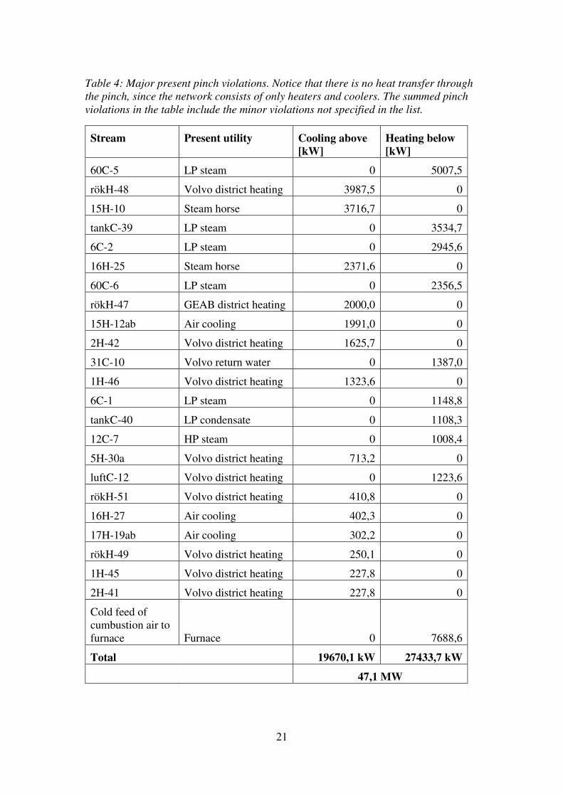
In order to achieve the theoretical hot and cold minimum demands presented above all pinch violations must be removed. In Table 4 below, the major pinch violations in the present system are listed together with the utility in use.
21
Table 4: Major present pinch violations. Notice that there is no heat transfer through the pinch, since the network consists of only heaters and coolers. The summed pinch violations in the table include the minor violations not specified in the list.
Stream Present utility Cooling above
[kW]
Heating below
[kW]
60C-5 LP steam 0 5007,5
rökH-48 Volvo district heating 3987,5 0
15H-10 Steam horse 3716,7 0
tankC-39 LP steam 0 3534,7
6C-2 LP steam 0 2945,6
16H-25 Steam horse 2371,6 0
60C-6 LP steam 0 2356,5
rökH-47 GEAB district heating 2000,0 0
15H-12ab Air cooling 1991,0 0
2H-42 Volvo district heating 1625,7 0
31C-10 Volvo return water 0 1387,0
1H-46 Volvo district heating 1323,6 0
6C-1 LP steam 0 1148,8
tankC-40 LP condensate 0 1108,3
12C-7 HP steam 0 1008,4
5H-30a Volvo district heating 713,2 0
luftC-12 Volvo district heating 0 1223,6
rökH-51 Volvo district heating 410,8 0
16H-27 Air cooling 402,3 0
17H-19ab Air cooling 302,2 0
rökH-49 Volvo district heating 250,1 0
1H-45 Volvo district heating 227,8 0
2H-41 Volvo district heating 227,8 0
Cold feed of cumbustion air to furnace Furnace 0 7688,6
Total 19670,1 kW 27433,7 kW
47,1 MW

22
The main pinch violations are cooling above the pinch using district heating and heating below the pinch using low pressure steam. A reason for this is the temperature intervals at which these utilities work. Low pressure steam is condensed at 146 °C, only 12 °C higher than the pinch temperature. District heating water is delivered at 90 °C and 130°C to GEAB and Volvo respectively, which means that many of the streams used to heat the district heating system must be cooled above the pinch. Another large contributor to the pinch violations is heating of the combustion air in the furnaces below the pinch temperature. This follows from that cold combustion air is currently directly injected in the most furnaces without any preheating.
The chosen value of ∆Tmin/2 can have drastic effect on the shape of the GCC and hence the minimum heating and cooling demand. It was tested using half and double the actual value of ∆Tmin/2, with a change in the pinch temperature of only a few degrees Celsius and no significant change in minimum hot and cold utility need. The main pinch violations mentioned above still remained in both cases.

23
6 Retrofit suggestion
As has been shown in the analysis of the present system there is potential to decrease the energy consumption at Preemraff Göteborg. As earlier described the system boundaries are limited to streams using utilities, and streams identified as having a potential for heating or cooling like preheating of the combustion air and further cooling of flue gases. The possibility for energy savings can be summed in 6 points.
1. Preheating of combustion air. This will decrease the fuel demand in the furnace.
2. Preheating cold process streams before heated in a furnace. This will decrease the energy consumption in the furnace.
3. Further cooling of flue gases. Currently most furnaces have stack temperatures that are higher than necessary.
4. Replacing whole or part of a steam-driven heater with a hot process stream. 5. Replacing whole or part of an air cooled exchanger with a cold process stream. 6. Produce steam in steam generators and thereby decreasing the production of
steam in the steam boilers.
The Matrix method, presented in chapter 2.2.1 Matrix method and 4.4 The Matrix method, has been used to select streams for the retrofit proposal. The large number of streams has made the selection strict, keeping only the streams with highest potential from an energy and economical point of view. See Appendix 3 – Matrix with duty above the pinch and Appendix 4 – Matrix with duty below the pinch for the matrices above and below the pinch, containing the corresponding duties for all possible matches between the process streams.

24
6.1 Retrofit proposal
A retrofit proposal, presented below, has been produced using the Matrix method.
Table 5: Retrofit proposal
Hot
stream
Cold
stream Duty,
[kW] Individual
duty
hot/cold,
[kW]
Piping
distance,
[m]
Utility in use,
hot/cold stream
Flue gases [rökH-47]
Crude oil [förvC-27] 1974 2000/26100 0
District heating/ Furnace
Reactor effluent [5H-30cd]
Reboiler [6C-2] 2946 20000/2946 190
Air cooling / LP steam
Residue [2H-41]
Reboiler [6C-1] 1149 2088/1149 200
District heating/ LP steam
Flue gases [rökH-50]
Combustion air [luftC-14] 459 459/578 0
Flue gas/ Combustion air
Reactor effluent [3H-31]
Combustion air [luftC-23/24/25] 1265 4249/2182 300
Air cooling/ Combustion air
Flue gases [rökH-54]
Reboiler [9C-4] 1571 1571/5007 0
Flue gas/ LP steam
Condenser [9H-7ab]
Reboiler [60C-5] 1442 1656/5007 550
Air cooling/ LP steam
Product to tank [12H-24]
Water to deionization [tankC-40] 665 1514/665 100
Air cooling/ LP condensate
Condenser [15H-12ab]
Reactor inlet [12C-7] 1452 1991/1452 480
Air cooling/ HP steam
Total 12923 kW
From Table 5 it can be seen that the retrofit suggestion is able to recover 12,9 MW by internal heat exchanging of process streams. This will save 12,9 MW of hot utility and 10,9 MW of cold utility. The lower value of cold utility is a consequence from that the flue gases is not cooled with any cold utility with exception for rökH-47 that is connected to the GEAB system.The major decrease in usage of utilities is distributed as:
• 1,45 MW of HP steam • 7,11 MW of LP steam • 1,72 MW of fuel gas by preheating of combustion air • 1,97 MW of fuel gas by preheating of streams heated in the furnace

25
• 7,77 MW of air cooling • 1,15 MW of Volvo district heating • 1,97 MW of GEAB district heating
The main decrease in cold utilities is the air cooling. Compared to the district heating system the air coolers do not bring any income, it is also preferable to lower the dependence on the air-cooled exchangers during the summer. The air cooled exchangers are, in some cases, replacing coolers connected to the district heating system during the summer since the need for district heating is low. Due to the studied period it is likely that the decreased deliveries to the district heating system will decrease further during winter. The deliveries to the district heating system is decreased by 3,1 MW in the retrofit proposal.
It is not always wanted to replace a district heating cooler, in many cases the district heating water itself can be used to replace more expensive hot utilities with small piping costs. This is shown further in chapter 6.3 District heating. For saving fuel gas in the furnaces preheating has been proposed at both the air and process streams heated in the furnaces. Heat is brought both from replacing air and district heating coolers and from cooling the flue gases further than that is presently done.

26
Figure 7: The proposed retrofit. Unchanged streams are not displayed.

27
6.1.1 Pinch violations
When doing a retrofit using pinch analysis one of the goals is to remove pinch violations from the existing system, and not bringing any new violations into the system. In the proposed retrofit design there are three pinch violations shown in Table 6, all of the character heating through the pinch.
Table 6: Pinch violations for the retrofit proposal above
Hot stream Cold stream Pinch violation, [kW]
Residue [2H-41]
Reboiler [6C-1] 228
Flue gases [rökH-50]
Combustion air [luftC-14] 459
Condenser [15H-12ab]
Reactor inlet [12C-7] 1008
Total pinch violation 1695 kW
The suggested heat exchangers will have approximately 1,7 MW of pinch violations.
The proposal will remove in total 11,5 MW pinch violations from the existing system. The reason this value does not equal the 12,9 MW presented in the retrofit proposal is that the match between rökH-54 and 9C-4 don’t lead to any elimination of pinch violations. They were, however, not connected before making the proposed heat exchanger between them save energy, in this case LP steam.
6.1.2 Economy
All investments must be able to pay for themselves, either by allowing a higher production capacity or by decreasing the need for energy. An easy way to measure an investment´s economical potential is the simple payback period which is defined as
+", #"-. /01234 � 5�)06780�7 !367���9"� 2�-380 31 6")2�:6 6�
The heat exchangers proposed in the retrofit, their cost and the payback period is shown in Table 7 below. The price for a heat exchanger is explained in section 4.3 Economical aspects. The annual income is given by the price of the saved energy. Many of the new heat exchangers will require new pumping equipment due to the increased pressure drop. The cost for pumps, fans or compressors are however not included in the cost presented below. To include more indirect costs for the equipment a Lang factor7 of 4,7 is used.
7 A Lang factor is an empirical constant representing the many small expenses not included in the
equipment cost.

28
The price for steam is given as SEK/ton while the furnaces are given as SEK/MWh fuel. The efficiency of the furnaces and boilers are estimated as 85% and 90% respectively. Air cooling is assumed to be free, and the electric cost for running the fans is neglected. The income from district heating has been approximated as the mean price over the whole year and is given in SEK/MWh.
Table 7: Investment cost and pay-back-period for both individual and total retrofit proposal.
Hot/cold stream Duty,
[kW]
Heat exchanger
and piping cost,
[MSEK]
Annual saving,
[MSEK/yr]
PBP,
[Year]
Flue gases/Crude oil [rökH-47/förvC-27] 1974 7,04 7,53 0,94
Reactor effluent/Reboiler [5H-30cd/6C-2] 2946 3,50 14,00 0,25
Residue/Reboiler [2H-41/6C-1] 1149 1,52 1,46 1,04
Flue gases/ Combustion air [rökH-50/luftC-14] 459 1,02 1,75 0,58
Reactor effluent/ Combustion air [3H-31/luftC-23/24/25] 1265 5,94 4,56 1,30
Flue gases/Reboiler [rökH-54/9C-4] 1571 1,57 7,47 0,21
Condenser/Reboiler [9H-7ab/60C-5] 1442 2,30 6,85 0,34
Product to tank/ Water to deionization [12H-24/tankC-40] 665 1,12 2,39 0,47
Condenser/Reactor inlet [15H-12ab/12C-7] 1452 1,82 8,11 0,22
Total 25,8 MSEK 54,1 MSEK/yr 0,48 yr

29
6.2 Emission savings
The possible energy savings, from the proposed retrofit, also results in decreased emissions. This contributes to a smaller impact on the environment and an economical saving for Preemraff because fewer carbon credits have to be bought. In Table 8 below one can see the individual emission savings for all suggested heat exchangers and the total. The calculations is based on that natural gas is on the margin with an emission factor of 15 gC/MJ. [21] An efficiency of 0,85 for the furnaces and 0,9 for the boilers is also used by consultation with Preem. [19]
The suggested retrofit will decrease the carbon dioxide emissions with approximately 25 kton, 4,7 % of the total CO2 emissions from Preemraff Göteborg, annually. [23] For comparison an average car emits 2,7 ton CO2 per year, see Appendix 5 – Emissions for a car for assumptions and calculations. Making this reduction correspond to emissions from approximately 9300 cars.
Table 8: Resulting decrease in CO2 emission
Hot
stream
Cold
stream
Replaced
utility
Qeff,
[kW]
Qeff,
[TJ/yr]
Qfuel,
[TJ/yr]
Emissions,
[ktCO2/yr]
Flue gases [rökH-47]
Crude oil [förvC-27]
Flue gas/ Furnace 1974 62,3 73,2 4,03
Reactor effluent [5H-30cd]
Reboiler [6C-2]
Air/ LP steam 2946 92,9 103,2 5,68
Residue [2H-41]
Reboiler [6C-1]
Volvo/ LP steam 1149 36,2 40,3 2,21
Flue gases [rökH-50]
Combustion air [luftC-14]
Flue gas/ Furnace 459 14,5 17,0 0,94
Reactor effluent [3H-31]
Combustion air [luftC -23/24/25]
Air/ Furnace 1265 39,9 44,3 2,44
Flue gases [rökH-54]
Reboiler [9C-4]
Flue gas/ LP steam 1571 49,5 55,0
3,03
Condenser [9H-7ab]
Reboiler [60C-5]
Air/ LP steam 1442 45,5 50,5
2,78
Product to tank [12H-24]
Water to deionization [tankC-40]
Air/ LP condensate 665 21,0 23,3
1,28
Condenser [15H-12b]
Reactor inlet [12C-7]
Air/ HP steam 1452 45,8 50,9
2,80
Total 12923 407,5 457,8 25,2

30
The reduction of CO2-emissions results in an annual saving of 4,82 MSEK in carbon credits, based on a carbon credit cost of 18,7 Euro/tCO2 and the assumption that 1 Euro costs 9 SEK . Apart from decreasing the emission of carbon dioxide, other pollutants such as sulphur- and sodium oxides also decrease. These can cause acidification, eutrophication, health issues and a reinforcement of the global greenhouse effect. [11]
6.3 District heating
The district heating system is used to remove excess heat from the process plant. GEAB and Volvo pays for the delivered heat but during the summer when need for district heating is low, the economical winning are small. When district heating cannot be used to remove excess heat, air coolers are used as a replacement. The capacity of the air coolers is limited and it would be beneficial both from an energy savings perspective and a process robustness view to be able to use the energy elsewhere.
One way of utilizing the excess energy better during the summer is to use the district heating water system as a hot utility on site. Presently it is only used in two places but the hot district heating water has the potential to replace low pressure steam and preheat combustion air in many places. In Table 9 below are a few suggestions of places where district heating could be used as a hot utility.
Table 9: Some potential internal uses for district heating
Cold stream Tstart, °C Ttarget, °C Duty, kW Utility
Reboiler, [60C-5] 112 112 5007 LP steam Reboiler, [60C-6] 112 112 2356 LP steam Caustic water, [12C-9] 37 47 25 LP steam Resudie tank, [tankC-39] 60 70 1108 LP steam All combustion air, [luftC-XX] 17 150 216 to 3278 Furnace
A stream with large potential for using district heating is tankC-39, heating of the residue tanks. At present the heat is delivered through low pressure steam. The location in the tank-park makes it inappropriate to heat exchange with any stream in the main refinery area, due to the distance and that currently used pipes is not constructed to high temperatures. The pipes delivering district heat to Volvo however passes close to the tanks and to reroute a portion of the hot water might be possible.
Preheating of combustion air is also an option. Volvo district heating water is currently used to preheat the combustion air into one of the furnaces that heats the crude oil, and is something that could be done on more furnaces.
Apart from being able to use the district heating system as a hot utility there are some streams that could be cooled by the district heating system. The possibility to produce more district heating has not been investigated further although some conclusions and suggestions are given in the discussion.

31
7 Discussion
The studied system has a theoretical potential for saving 40,2 MW of hot utility and 47,8 of cold utility. It would however not be economically feasible to reconstruct the system to achieve this saving. Instead a retrofit proposal containing 10 new heat exchangers saving 12,9 MW of hot and 10,9 MW of cold utilities has been identified.
The data used in this pinch analysis is collected for a summer case when producing MK1 diesel. During the summer, demand for district heating is low leading to an increased use of air cooling. Differences in air temperature between seasons are of smaller meaning since most energy consumers are well isolated, even if some pipes need extra heating to avoid freezing during the winter. The production of MK1 diesel requires less energy than other qualities due to lower production rates. Further studies concerning the impact of producing a different quality, or seasonal aspects, is necessary. When producing the retrofit proposal deviation from the studied period has been kept in mind.
7.1 Retrofit
The retrofit proposal presented in Table 5 consists of 10 pair of streams that can be heat exchanged instead of using utilities for cooling and heating.
As mentioned earlier, the proposal has been discussed with Cecilia Hellman at Preemraff Göteborg. Some of the aspects brought up and some general comments about the proposed heat exchangers are listed below.
• RökH-47 / förvC-27
The purpose of this heat exchanger is to preheat the crude oil, using the hot flue gases, before entering the furnace. The proposed heat exchanger would replace ECO-4 which currently cools flue gases to the district heating system. The economizer is located after the superheater but before the recuperator8. An option to this suggestion would be reconstruction of either the convection bank or the air preheater to allow for a replacement of eco-4. Studies have been done at Preemraff Göteborg about modifying the superheater but they have all assumed that ECO-4 remains in its place. Preheating the crude oil would mean higher driving forces than possible in a reconstructed superheater.
• 5H-30cd / 6C-2
The fan, 5H-30cd, is presently working with a high load. Removing some of its load is wanted also from a process robustness view. [19] As seen in Table 5: Retrofit proposal, the fan will still be needed to a large extent. Only a smaller side stream needs to be extracted from it. The low temperature required in the reboiler, 6C-2, means that the Volvo district heating water could be used to heat it. Unfortunately, the Volvo district heating system is not present close to the reboiler and much piping would be needed.
8 Heat exchanger heating combustion air using flue gases

32
• 2H-41 / 6C-1
The residue is currently cooled to the district heating system and by cooling water. The residue must be cooled to a certain temperature, meaning that the cooling water will still be needed. The piping needed to connect the residue to the reboiler is rather large.
• rökH-50 / luftC-14
Preheating the combustion air to the furnace means that less fuel is needed. The combustion air is currently brought in through several individual inlets, one for each burner. This means that, besides the recuperator itself, an air channel and a fan is needed.
• 3H-31 / luftC23/24/25
3H-31 has been studied earlier with the purpose of creating district heating but it has not been found economically possible. [11] Two of the air inlets above are connected to the same air channel meaning that only two units in total are needed. The third furnace is situated separately from the other two. The temperature of the combustion air will be below the intended 150°C although it is not a problem because of its soft target.
• rökH-54 / 9C-4
rökH-54 is the flue gas from the incinerator. The purpose of the incinerator is to combust sulphur containing gas at a high temperature where it is degraded. It would therefore require reconstruction before being able to cool its flue gases. The distance to 9C-4 is small.
An alternative to this proposal is to produce steam in the incinerator whilst heating 9C-4 with district heating water. Using district heating water for 9C-4 would require extensive repiping though.
• 9H-7ab / 60C-5
The unit where 60C-5 is situated is built separately from the rest of the refinery, meaning that long piping is required for this proposal. Otherwise it is very beneficial, space to build is available and there is no competition with the district heating system.
• 12H-24 / tankC-40
Heating the raw water a few degrees will both increase efficiency in the water treaters and save fuel in the steam boilers. Distance between the two streams is small and there is plenty of room to build around the raw water pipe.
• 15H-12ab / 12C-7
15H-12ab is an air cooled exchanger operating as a complement to the district heating system. Distance between the two streams is unfortunately rather long.

33
Some potential retrofitted heat exchangers are not included in this proposal. Reasons for rejecting possible matches are mainly distance between the matching streams and construction limitations. The process plant is very large and the streams subjected to this study are brought from all areas of the site making long distances possible. When deciding whether a distance is too long, duty and other variables have been taken into account. There are more reasons for not recommending a heat exchanger to be constructed than distance. For example removing a steam generator, producing LP steam, and instead using it to replace a reboiler using HP steam are not economically possible. Exchanging heat between flue gases and combustion air has been limited to being possible only in the same furnace due to the large pipes required for gas at atmospheric pressure.
There are complications that are of a more complex nature. These can be of the mechanical sort, for example it is not possible to preheat the combustion air to some of the furnaces due to location and type of the existing air inlet. The most obvious problems have been detected with help from Cecilia Hellman [19] and been avoided.
This retrofit proposal has 1,7 MW of pinch violations built in, however 11,5 MW is removed by constructing it. The pinch violations that will be built in by the retrofit proposal will not directly increase the energy demand of the refinery. They will however, make future retrofits more expensive since the pinch violations must be removed in order to get closer to a MER network.
7.2 The district heating system
As shown there are many possibilities for exchanging process streams directly with each other. However the profitability and logic of this is decreased when one of them is a cooler to the district heating system, since this generates revenue. Even so it is always preferable to make use of the energy on site, since this lower the demand of utilities. The district water systems are all over the site meaning that there is seldom a long distance to the nearest pipe, as opposed to building a process/process heat exchanger requiring lots of piping. As shown in Table 9 the possibilities for replacing some low pressure steam heaters with the current district heating water system is good. There are some requirements of how much heat can be taken out of the system and especially at high temperatures of the district heating system. It should be noticed that the district heating system does not operate at one temperature; the delivered temperature is always the same though. This makes the usage of it more complex.
A good side of using the present district heating system is that it can bring heat out of the system also in the summer and thereby increase the capacity and take some load of the fans. Using the district heating system would also mean some, potential, flexibility.
Two of the places where using the district heating system for internal purposes seems to be most beneficial are for preheating combustion air and to heat the residue tanks, tankC-39. The residue tanks are currently using LP steam for heating the tanks to between 60°C and 70°C. The low temperature makes switching to another, cheaper, heat source possible.
As well as replacing LP steam in the tank park, the current district heating water can also be used to preheat combustion air. This has already been done in one of the

34
furnaces for the crude oil. The district heating water is first heated in an economizer, and part of that hot water heats the combustion air to 140°C. The target temperature of 150 °C is a soft target meaning that all district heating water of all temperatures can be used, even though they can’t raise the temperature to 150 °C.
A side track brought from the pinch analysis and gathering of data is that there is a potential for more delivery to the district heating system. Some of the streams with possibility to deliver heat to the district heating system are shown below.
Table 10: Some streams with potential for delivering district heating
Hot stream Duty, [kW] Temperature, [ºC]
rökH-49 500 360-180
rökH-53 3455 293-180
rökH-54 1571 700-180
rökH-51 787 410-180
15H-13 7001 140-35
16H-27 2816 153-55
Both rökH-53 and 15H-13 are connected in series with cooler connected to the district heating system at present. Finding ways to use district heating system on site would mean that less heat would be sent to air cooled exchangers during the summer.
7.3 Economy
The economical estimates presented in the chapter 6.1.2 are approximate. Apart from the heat exchanger and piping there are many costs associated. It is likely that the proposed heat exchangers will introduce higher pressure drops than earlier requiring that a pump or a fan is installed. The installation cost is also a large contributor to the final cost. The main effect would be the PBP which would increase, however the PBP is very low at the moment so it would probably not lead to any new rejections.
A further and more accurate cost estimate is needed. As it is now the results are, as mentioned earlier, based on that all heat exchangers are of the type tube and shell which might not always be the best choice. In reality there are perhaps more efficient heat exchanger types suited for the job. For the gas/gas heat exchangers as well as the ones involving condensation and evaporation the model presented in chapter 4.3 Economical aspects will not be as accurate.
The cost for constructing and installing a proposed unit can differ due to many reasons. For example preheating of combustion air into two of the high pressure steam boilers is easier than the other places since they have a prepared air inlet channel. Many of the proposed heat exchangers will not be necessary to construct from scratch. Reconstruction of tube and shell heat exchangers, as are used now, is common. Usually the tube bundle is replaced while keeping the shell thereby changing the area of the heat exchanger.

35
8 Conclusions
The studied system currently uses 114,3 MW and 159,5 MW respectively of hot and cold utility, and contains 47,1 MW of pinch violations.
The retrofit suggestion consists of 10 heat exchangers replacing usage of utilities completely or partly. It would decrease the hot and cold utility demand with 12,9 MW respectively 10,9 MW with an investment cost of 25,8 MSEK and a payback time of 0,48 year. The delivered load to the district heating system will decrease with 3,1 MW.
The heat exchangers are replacing hot utilities by preheating combustion air to furnaces, preheating hydrocarbon streams to furnaces, replacing part or whole reboilers and heaters using steam. The cold utilities are saved by replacing air cooled exchangers and coolers connected to the district heating system.
Apart from heat exchanging process streams directly, the district heating system could be used internally to replace hot utilities. Two places where utility usage could be decreased are heating of the residue tanks and preheating of combustion air. The residue tanks are currently heated with low pressure steam to 60 °C and many of the furnaces does not have preheating of the combustion air.

36

37
9 Further work
In a society with increasing costs of fossil fuel and carbon credits it must be remembered that earlier rejected investments can be both attractive and profitable in the future.
Based on the proposed retrofit it would be preferable to make more rigorous economic calculation of the proposed heat exchangers than the estimations done in this project. This includes better values for the overall heat transfer coefficient, more precise values for the piping distance and an evaluation of using other types of heat exchangers than a tube and shell heat exchanger. It would also be desirable to investigate the possibility to keep some of the existing heat exchangers and replace the utility with the process stream instead of investing in new heat exchangers and scrap the old ones. Another example worth investigating is the possibility to have two separate tube packet inside the same shell, one for a process stream and on for steam, instead of two heat exchangers in a sequence. This can be an option for the reboilers that are not completely satisfied with the heat integration and therefore still need a certain amount of steam, for example 13C-3 and 60C-5.
Because the possibility of preheating the crude oil feed from tank not was investigated since it includes process/process heat exchangers it is of large interest to look further into this. An advantage when doing so is that this master thesis has located possible heat sources that might be used. It is also preferable to look at the option to preheat the fraction of the feed to the two DHT units coming from tank, before entering the existing heat exchangers 3E-1 and 4E-1, since like the crude oil it would decrease the demand of the furnaces with equal amount.
One option that was discussed with our supervisor at Preem, Cecilia Hellman, was that an interesting point of view is if the district heating system instead is seen as a hot water system that can be used to preheat different process streams within the refinery. As it is constructed today the district heating system is well integrated in the plant and could be a good option to transfer heat throughout the process instead of building new pipes for the process streams. This results in that even more heat could be transferred into the district heating system without increasing the amount of heat delivered to GEAB and Volvo and is something that is recommended to further investigate.

38

39
10 References
[1] Preem AB. (2010). Årsredovisning 2009. Available at: http://www.preem.se/upload/Arsredovisning/PreemPres09-sv.pdf [2011-01-20]
[2] European Commision. (2008). EU action against climate change. Available at: http://ec.europa.eu/climateaction/eu_action/index_en.htm [2011-01-21]
[3] Preemraff Göteborg (2009). Miljörapport 2009. [4] E.On. Jämför din förbrukning. Available at: http://www.eon.se/templates/Eon2TextPage.aspx?id=47760&epslanguage=SV [2011-05-09]
[5] Preem AB (2009). Årsredovisning 2008. Available at: http://preem.se/upload/Arsredovisning/PreemPres_sv_08.pdf [2011-01-25]
[6] Ebrahim, M. (2000). Pinch technology: An efficient tool for chemical-plant energy and capital-cost saving. Applied Energy vol. 65 p. 45–49
[7] Kemp, I. C. (2007). Pinch Analysis and Process Integration: A user guide on process integration for efficient use of energy. Second edition, Butterworth-Heinemann, Oxford, UK p. 1-40
[8] Berntsson, T and Franck, P-Å. (2008). Pinch Analysis and Retrofit of Existing Processes. Gothenburg: Chalmers University of Technology. Course material in Industrial Energy Systems, 2008
[9] Wieringa, K and Nickson, J. (2005). Energy Improvement Program at Preemraff Gothenburg. Gothenburg, Shell Global Solutions. Internal report at Preemraff Göteborg
[10] Fransson R. (1998). Utökning av fjärrleveranser från Preem raffinaderi. Examensarbete vid institutionen för Kemiteknik och miljövetenskap/Värmeteknik och maskinlära
[11] Wennerberg, T. (2005). Energiutredning enligt villkor E4 i deldom 2002-07-03. Unpublished report. Göteborg: Preem
[12] Statens energimyndighet (2010). Energiläget 2010. Available at: http://webbshop.cm.se/System/TemplateView.aspx?p=Energimyndigheten&view=default&cat=/Broschyrer&id=6792e3736ce045c4a41f2c397b1eff97 [2011-01-25]

40
[13] Göteborgs energi AB (2010). Göteborg energi årsredovisning 2009 del 2. Available at: http://www.goteborgenergi.se/Om_oss/Finansiell_information/Arsredovisningar?GeneralInfoListCategory=9851572 [2011-01-25]
[14] Foster Wheeler. (2000). Heating System Review. Göteborg. Internal report at Preemraff Göteborg
[15] Kemp, I. C. (2007). Pinch Analysis and Process Integration: A user guide on process integration for efficient use of energy. Second edition, Butterworth-Heinemann, Oxford, UK p. 296
[16] Sinnott, R. and Towler G. (2009). Chemical Engineering Design, Fifth Edition, Butterworth-Heinemann, Oxford, UK, p. 817-821
[17] Sinnott, R. and Towler, G. (2009). Chemical Engineering Design, Fifth Edition, Butterworth-Heinemann, Oxford, UK, p. 312-317
[18] Chemical Engineering. New York: May 2007. Vol. 114, Iss. 5; pg. 95
[19] Discussions with Cecilia Hellman, process engineer and supervisor at Preemraff Göteborg
[20] Chemical Engineering. New York: Apr 2011. Vol. 118, Iss. 4; pg. 67
[21] Azar, C. (2010) Thinking about energy systems: Concepts and tools. Gothenburg: Chalmers University of Technology. Course material in Sustainable Energy Futures, 2010
[22] Eriksson, L. and Hermansson, S. (2010) Pinch analysis of Billerud Karlsborg, a partly integrated pulp and paper mill. Master thesis at the department of energy and enviroment, Heat and Power technology. Göteborg: Chalmers university of technology.
[23] Preemraff Göteborg (2010). Miljörapport 2010.

41
11 Appendix 1 – Stream data
Hot streams
# Tstart, [°C] Ttarget, [°C] Cp, [J/kgK] ∆Hvap, [kJ/kg] Q, [kW]
6H-1 80 35 2720 363 6H-3a 90 55 2934 256 6H-3b 75 75 262 220 13H-4 80 80 332 11069 14H-5 265 165 2121(1) 37 9H-6 65 40 3510 2156 9H-7a 122 122 2202 1442 9H-7b 122 44 4200 215 60H-8 117 90 2578 1179 60H-9 105 87 250(2)
15H-10 172 150 2121(1) 3717 15H-11a 110 30 7239 1054 15H-11b 30 30 182 321 15H-12a 195 165 1870 35 15H-12b 165 165 1087 1956 15H-13 140 35 2364 7002 17H-14 122 45 4248 1275 17H-15a 119 119 1296 203 17H-15b 119 96 4298 2 17H-16 90 32 14400 543 17H-17 95 35 14400 562 17H-19a 150 65 2854(3)
17H-19b 110 110 1871(3)
17H-20 125 22 2361 63 12H-21 80 25 5213 114 12H-22 85 35 1902 1549 12H-23a 80 35 2291 65 12H-23b 60 60 317 1289 12H-24 82 35 2520 1514 16H-25a 230 160 2121(1) 2372 16H-26 144 22 2216 466 16H-27 153 55 2514 2816 16H-28a 153 120 2397 12 16H-28b 135 135 669 277 5H-29 70 33 2061 2010 5H-30a 150 128,2 3276 2593 5H-30b 125 125 365 3407 5H-30c 128,2 30 4036 (gas), 1989 (liq) 8966 5H-30d 65 65 601 11034

42
# Tstart, [°C] Ttarget, [°C] Cp, [J/kgK] ∆Hvap, [kJ/kg] Q, [kW]
3H-31 115 50 2315 4249
3H-32a 72 40 2010 71 3H-32b 55 55 327 1289 3H-33 105 30 2013 567 3H-34 115 60 2286 1415 4H-35 105 30 2091 221 4H-36 120 45 2315 5049 4H-37a 72 40 2010 95 4H-37b 55 55 327 1718 4H-38 115 35 2268 3185 2H-39a 100 80 5163(4)
2H-39b 85 85 6837(4)
2H-40a 80 44 9035(5)
2H-40b 65 65 3131(5)
2H-41 145 90 2036 2088 2H-42 215 55 2608 3423 1H-43a 100 80 4732(4) 1H-43b 90 90 6268(4) 1H-44a 80 45 8282(5)
1H-44b 65 65 2870(5)
1H-45 145 95 2036 1898 1H-46 205 55 2608 3008 rökH-47 365 264 1,45 2000 rökH-48 385 187 1,45 3988 rökH-49 360 180 1,45 500 rökH-50 275 180 1,45 459 rökH-51 410 180 1,45 787 rökH-52 210 180 1,45 175 rökH-53 293 180 1,45 3455 rökH-54 700 180 1,45 1571 rökH-56 270 180 1,45 254 rökH-57 275 180 1,45 172
(1) Enthalpy of vaporization for saturated water at 3,5 barg
(2) Load taken directly from Aspen Process Explorer
(3) The sum of loads of 17H-14 and 17H-19 where given directly by Aspen Process Explorer. The load of 17H-14 could then by subtracted.
(4) Load taken directly from Aspen Process Explorer and divided into the condensing fraction and cooling fraction.
(5) Load taken directly from simulation in PROII.

43
Cold streams
# Tstart, [°C] Ttarget, [°C] Cp, [J/kgK] ∆Hvap, [kJ/kg] Q, [kW]
6C-1 103 103 2121(1) 1149 6C-2 84 84 2121(1) 2946 13C-3 144 144 1935(2) 11288 9C-4 129 129 2121(1) 5007 60C-5 112 112 2121(1) 5007 60C-6 112 112 2121(1) 2356 12C-7 104 140 1935(2) 1452,1 12C-8 162 162 1935(2) 3485,1 12C-9 37 47 2121(1) 24,743 31C-10 20 50 4182 1387 luftC-11 147 150 1,013 37 luftC-12 17 150 1,009 1521 luftC-13 17 150 1,009 333 luftC-14 17 150 1,009 578 luftC-15 17 150 1,009 410 luftC-16 17 150 1,009 699 luftC-17 17 150 1,009 3278 luftC-18 17 150 1,009 361 luftC-19 17 150 1,009 361 luftC-20 17 150 1,009 386 luftC-21 17 150 1,009 337 luftC-22 17 150 1,009 217 luftC-23 18 150 1,009 813 luftC-24 22 150 1,009 742 luftC-25 17 150 1,009 627 luftC-26 30 150 1,009 435 förvC-27 250 375 2762 26100 förvC-28 250 375 2762 25050 förvC-29a 243 243 6 33 förvC-29b 243 295 2705 1814 förvC-30 195 210 2716 6469 förvC-31a 245 245 6 33 förvC-31b 245 300 2705 1919 förvC-32 200 210 2716 7426 förvC-33 232 248 2960 5912 förvC-34a 238 238 551 867 förvC-34b 238 320 3440 2397 tankC-39 60 70 2121(1) 3535 tankC-40 10 35 4200 1108
(1) Enthalpy of vaporization for saturated water at 3,5 barg
(2) Enthalpy of vaporization for saturated water at 15 barg

44

45
12 Appendix 2 – heat transfer coefficient
Fluid Phase h- value [W/m2K]
Air Gas 50
Light oil Gas 50
Light oil Gas, high pressure 300
Light oil Liquid 500
Light oil Condensing 1000
Light oil Evaporating 1100
Heavy oil Liquid 800
Brine Liquid 1000
Cooling tower water Liquid 1250
Lean amin, (dilute aq) Liquid 1500
Water Condensate 2000
Water Condensing vapour 2700
In the case were a stream consists of both gas and liquid a weighted value has been used based on the quota between gas and liquid.

46

47
13 Appendix 3 – Matrix with duty above the pinch

48
Numbers within the cells represents the potential heat exchanger duty. A zero indicates that heat exchanging is not possible due to temperatures.

49
14 Appendix 4 – Matrix with duty below the pinch
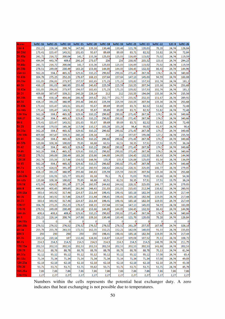
50
Numbers within the cells represents the potential heat exchanger duty. A zero indicates that heat exchanging is not possible due to temperatures.

51
15 Appendix 5 – Emissions for a car
�)"1":0 412)2�: 4267"�-0 � 15000 .8,1
=90� -3�698/723� � 0,07 @ :"63�2�0.8
&�01:, -3�70�7 3A :"63�2�0 � 34,5 BC@
!"1#3� 0826623� A"-731 � 20 :!BC
B3�0 D02: 7 3A !E� � 44 :83�
B3�0 D02: 7 3A ! � 12 :83�
Above values are all taken from the course book in Sustainable Energy Futures. [20]
Resulting emission from a car assumed driven on gasoline:
0 � 4267"�-0,1 · -3�698/723�
4267"�-0 · 0�01:, -3�70�7 · 0826623� A"-731 · BFGHBF
0 � 1500 · 0,7 · 34,5 · 20 · 4412 � 2656500 :!E�
,1 I 2,7 73�!E�,1

52

chalmers university of technologyse 412 96 Gothenburg, SwedenPhone: + 46 - (0)31 772 10 00Web: www.chalmers.se
Investigation of the opportunity for
heat integration at Preemraff Göteborg
Master’s Thesis within the Innovative and Sustainable Chemical Engineering programme
ROBIN GOTTFRIDSSON & ISABELLE JOHANSSON Department of Energy and Environment Division of Heat and Power Technology CHALMERS UNIVERSITY OF TECHNOLOGY Göteborg, Sweden 2011