invitation for bid (ifb) # mack facility reroofing
TRANSCRIPT

Invitation for Bid (IFB) #
Mack Facility Reroofing Building
Envelope Repairs 20234 Mack Street
Hayward, CA 94545
Architect Interactive Resources, Inc
117 Park Place Richmond, CA 94801
www.intres.com
September 18, 2018
Alameda-Contra Costa County Transit District

AC Transit TABLE OF CONTENTS 09/18/18 Oakland, CA SECTION 00 01 10 – Page 1 of 3
Section 00 01 10 Table of Contents
Division Section Title Date Pages
PROCUREMENT AND CONTRACTING DOCUMENTS GROUP
DIVISION 0 - BIDDING AND CONTRACTING REQUIREMENTS 00100 NOTICE INVITING BIDS 100200 INSTRUCTIONS TO BIDDERS 500300 PRE-BID CONFERENCE 1300400 BID FORMS 1500410 SCHEDULE OF BID PRICES 6600490 BIDDING ADDENDA 7100500 CONTRACT 7300600 CONTRACT BONDS 7900700 GENERAL CONDITIONS 8700800 SPECIAL PROVISIONS 16300820 FEDERAL REQUIREMENTS 16400840 PREVAILING WAGES 18300860 INSURANCE REQUIREMENTS 187
SPECIFICATIONS GROUP
General Requirements Subgroup
DIVISION 01 - GENERAL REQUIREMENTS 011000 SUMMARY 09/18/18 4012500 SUBSTITUTION PROCEDURES 09/18/18 4012600 CONTRACT MODIFICATION PROCEDURES 09/18/18 3012900 PAYMENT PROCEDURES 09/18/18 6013100 PROJECT MANAGEMENT AND COORDINATION 09/18/18 10013200 CONSTRUCTION PROGRESS DOCUMENTATION 09/18/18 10013300 SUBMITTAL PROCEDURES 09/18/18 14014000 QUALITY REQUIREMENTS 09/18/18 10015000 TEMPORARY FACILITIES AND CONTROLS 09/18/18 6016000 PRODUCT REQUIREMENTS 09/18/18 6017300 EXECUTION 09/18/18 8017700 CLOSEOUT PROCEDURES 09/18/18 7017823 OPERATION AND MAINTENANCE DATA 09/18/18 8017839 PROJECT RECORD DOCUMENTS 09/18/18 5

AC Transit TABLE OF CONTENTS 09/18/18 Oakland, CA SECTION 00 01 10 – Page 2 of 3
DIVISION 02 - EXISTING CONDITIONS 02 41 19 SELECTIVE DEMOLITION 09/18/18 6
DIVISION 03 – CONCRETE 03 30 53 MISCELLANEOUS CAST-IN-PLACE CONCRETE 09/18/18 7
DIVISION 05 – METALS 05 50 00 METAL FABRICATIONS 09/18/18 9
DIVISION 07 - THERMAL AND MOISTURE PROTECTION 07 25 00 WEATHER BARRIERS 09/18/18 207 41 13 METAL ROOF PANELS 09/18/18 1407 42 13 FORMED METAL WALL PANELS 09/18/18 607 62 00 SHEET METAL FLASHING AND TRIM 09/18/18 807 72 00 ROOF ACCESSORIES 09/18/18 607 84 13 PENETRATION FIRESTOPPING 09/18/18 507 92 00 JOINT SEALANTS 09/18/18 5
DIVISION 08 - OPENINGS 08 62 00 UNIT SKYLIGHTS 09/18/18 5
DIVISION 09 – FINISHES 09 91 13 PAINTING 09/18/18 6
DIVISION 23 – HEATING VENTILATING AND AIR CONDITIONING 23 05 17 SLEEVES AND SLEEVE SEALS FOR HVAC PIPING 09/18/18 523 05 18 ESCUTCHEONS FOR HVAC PIPING 09/18/18 223 05 29 HANGERS AND SUPPORTS FOR HVAC PIPING AND
EQUIPMENT 09/18/18 7
23 05 48 VIBRATION AND SEISMIC CONTROLS FOR HVAC 09/18/18 523 05 53 IDENTIFICATION FOR HVAC PIPING AND EQUIPMENT 09/18/18 523 05 93 TESTING, ADJUSTING, AND BALANCING FOR HVAC 09/18/18 1223 07 13 DUCT INSULATION 09/18/18 1023 07 19 HVAC PIPING INSULATION 09/18/18 1023 11 23 FACILITY NATURAL GAS PIPING 09/18/18 1323 23 00 REFRIGERANT PIPING 09/18/18 823 31 13 METAL DUCTS 09/18/18 1023 33 00 AIR DUCT ACCESSORIES 09/18/18 923 34 23 HVAC POWER VENTILATORS 09/18/18 423 37 13 DIFFUSERS, REGISTERS, AND GRILLES 09/18/18 3

AC Transit TABLE OF CONTENTS 09/18/18 Oakland, CA SECTION 00 01 10 – Page 3 of 3
23 62 13 VARIABLE FLOW REFRIGERANT HVAC EQUIPMENT 09/18/18 1923 74 23 PACKAGED, DIRECT-FIRED, OUTDOOR, HEATING-ONLY
MAKEUP-AIR UNITS 09/18/18 10
DIVISION 26 – ELECTRICAL 26 05 00 ELECTRICAL BASIC MATERIALS AND METHODS 09/18/18 1226 22 13 LOW-VOLTAGE DISTRIBUTION TRANSFORMERS 09/18/18 726 24 16 PANELBOARDS 09/18/18 11
END OF SECTION 00 01 10

AC Transit Oakland, CA
SUMMARY Section 01 10 00 – Page 1 of 4
9/18/18
SECTION 01 10 00 SUMMARY
PART 1 - GENERAL
1.1 RELATED DOCUMENTS
A. Drawings and general provisions of the Contract, including General and Supplementary Conditions and other Division 01 Specification Sections, apply to this Section.
1.2 SUMMARY
A. Section Includes:
1. Project information. 2. Work covered by Contract Documents. 3. Phased construction. 4. Access to site. 5. Coordination with occupants. 6. Work restrictions. 7. Specification and drawing conventions. 8. Miscellaneous provisions.
B. Related Requirements:
1. Section 01 50 00 "Temporary Facilities and Controls" for limitations and procedures governing temporary use of Owner's facilities.
1.3 PROJECT INFORMATION
A. Project Identification: Mack Facility Reroofing Building Envelope Repairs
1. Project Location: 20234 Mack Street, Hayward, CA 94545
B. Owner: AC Transit, 1600 Franklin Street, Oakland, CA 94612
1. Owner's Representative: Stephen P. Stanley
C. Architect: Interactive Resources, 117 Park Place, Richmond, CA 94801.
1. Architect of Record: Tom Butt
D. Construction Manager: TBD 1. Construction Manager may be engaged for this Project to serve as an advisor to District
and to provide assistance in administering the Contract for Construction between District

AC Transit Oakland, CA
SUMMARY Section 01 10 00 – Page 2 of 4
9/18/18
and Contractor, according to a separate contract between the District and Construction Manager.
E. District’s Web-based Project Management Software: The District provides a web-based Project Management Software to be used for purposes of managing communication and documents during the construction stage. 1. See Section 01 31 00 "Project Management and Coordination." for requirements for
using the District’s Project Management Software.
1.4 WORK COVERED BY CONTRACT DOCUMENTS
A. The Work of Project is defined by the Contract Documents and consists of the following:
1. Removing and replacing the existing metal roof and associated skylights. 2. Removing existing rooftop mechanical equipment and installing new mechanical
equipment. 3. Removing, making repairs and reinstalling portions of existing metal siding.
B. Type of Contract:
1. Project will be constructed under a single prime contract.
1.5 ACCESS TO SITE
A. General: Contractor shall have limited use of Project site for construction operations as indicated on Drawings by the Contract limits and as indicated by requirements of this Section.
B. Use of Site: Limit use of Project site to work in areas indicated. Do not disturb portions of Project site beyond areas in which the Work is indicated.
1. Driveways, Walkways and Entrances: Keep driveways loading areas, and entrances serving premises clear and available to Owner, Owner's employees, and emergency vehicles at all times. Do not use these areas for parking or storage of materials.
a. Schedule deliveries to minimize use of driveways and entrances by construction operations.
b. Schedule deliveries to minimize space and time requirements for storage of materials and equipment on-site.
C. Condition of Existing Building: Maintain portions of existing building affected by construction operations in a weathertight condition throughout construction period. Repair damage caused by construction operations.
1.6 COORDINATION WITH OCCUPANTS
A. Full District Occupancy: District will occupy site and existing adjacent building(s) during entire construction period. Cooperate with Owner during construction operations to minimize

AC Transit Oakland, CA
SUMMARY Section 01 10 00 – Page 3 of 4
9/18/18
conflicts and facilitate Owner usage. Perform the Work so as not to interfere with Owner's day-to-day operations. Maintain existing exits unless otherwise indicated.
1. Maintain access to existing walkways, corridors, and other adjacent occupied or used facilities. Do not close or obstruct walkways, corridors, or other occupied or used facilities without written permission from Owner and approval of authorities having jurisdiction.
2. Notify Owner not less than 72 hours in advance of activities that will affect Owner's operations.
1.7 WORK RESTRICTIONS
A. Work Restrictions, General: Comply with restrictions on construction operations.
1. Comply with limitations on use of public streets and with other requirements of authorities having jurisdiction.
B. On-Site Work Hours: Limit work in the existing building to normal business working hours of 6:00 a.m. to 4:00 p.m., Monday through Friday, unless otherwise indicated.
1. Weekend Hours: 6:00 a.m. to 5:00 p.m.
2. Hours of Core Drilling or other noisy activities: Notify Project Manager forty-eight (48) hours in advance of start of core drilling or other noise centric activity to allow time to notify District employees and the public, as well as to allow for coordination with ongoing District operations within the building.
C. Existing Utility Interruptions: Do not interrupt utilities serving facilities occupied by District or others unless permitted under the following conditions and then only after providing temporary utility services according to requirements indicated:
1. Notify District not less than two (2) days in advance of proposed utility interruptions.
2. Obtain District’s written permission before proceeding with utility interruptions.
D. Noise, Vibration, and Odors: Coordinate operations that may result in high levels of noise and vibration, odors, or other disruption to District occupancy with District.
1. Notify District not less than two (2) days in advance of proposed disruptive operations.
2. Obtain District’s written permission before proceeding with disruptive operations or perform disruptive operations that result in noise of 60 dBa or more in any occupied area on weekends or before 6:00 a.m. and after 5:00 p.m. on weekdays.
E. Nonsmoking Building: Smoking is not permitted within the building or within twenty-five (25)
feet of entrances, operable windows, or outdoor-air intakes.
F. Employee Identification: District will provide identification tags for Contractor personnel working on Project site. Require personnel to use identification tags at all times.

AC Transit Oakland, CA
SUMMARY Section 01 10 00 – Page 4 of 4
9/18/18
1.8 SPECIFICATION AND DRAWING CONVENTIONS
A. Specification Content: The Specifications use certain conventions for the style of language and the intended meaning of certain terms, words, and phrases when used in particular situations. These conventions are as follows:
1. Imperative mood and streamlined language are generally used in the Specifications. The words "shall," "shall be," or "shall comply with," depending on the context, are implied where a colon (:) is used within a sentence or phrase.
2. Specification requirements are to be performed by Contractor unless specifically stated otherwise.
B. Division 01 General Requirements: Requirements of Sections in Division 01 apply to the Work of all Sections in the Specifications.
C. Drawing Coordination: Requirements for materials and products identified on Drawings are described in detail in the Specifications. One or more of the following are used on Drawings to identify materials and products:
1. Terminology: Materials and products are identified by the typical generic terms used in the individual Specifications Sections.
2. Abbreviations: Materials and products are identified by abbreviations published as part of the U.S. National CAD Standard and scheduled on Drawings.
3. Keynoting: Materials and products are identified by reference keynotes referencing Specification Section numbers found in this Project Manual.
PART 2 - PRODUCTS (Not Used)
PART 3 - EXECUTION (Not Used)
END OF SECTION 01 10 00
AC Transit Oakland, CA
SUBSITUTION PROCEDURES Section 01 25 00 – Page 1 of 4
9/18/18
SECTION 01 25 00 SUBSTITUTION PROCEDURES
PART 1 - GENERAL
1.1 RELATED DOCUMENTS
A. Drawings and general provisions of the Contract, including General and Supplementary Conditions and other Division 01 Specification Sections, apply to this Section.
1.2 SUMMARY
A. Section includes administrative and procedural requirements for substitutions.
B. Related Requirements:
1. Section 01 60 00 "Product Requirements" for requirements for submitting comparable product submittals for products by listed manufacturers.
1.3 DEFINITIONS
A. Substitutions: Changes in products, materials, equipment, and methods of construction from those required by the Contract Documents and proposed by Contractor.
1. Substitutions for Cause: Changes proposed by Contractor that are required due to changed Project conditions, such as unavailability of product, regulatory changes, or unavailability of required warranty terms.
2. Substitutions for Convenience: Changes proposed by Contractor or Owner that are not required in order to meet other Project requirements but may offer advantage to Contractor or Owner.
1.4 ACTION SUBMITTALS
A. Substitution Requests: Submit three copies of each request for consideration. Identify product or fabrication or installation method to be replaced. Include Specification Section number and title and Drawing numbers and titles.
1. Documentation: Show compliance with requirements for substitutions and the following, as applicable:
a. Statement indicating why specified product or fabrication, or installation cannot be provided, if applicable.
b. Coordination information, including a list of changes or revisions needed to other parts of the Work and to construction performed by Owner and separate contractors, that will be necessary to accommodate proposed substitution.

AC Transit Oakland, CA
SUBSITUTION PROCEDURES Section 01 25 00 – Page 2 of 4
9/18/18
c. Detailed comparison of significant qualities of proposed substitution with those of the Work specified. Include annotated copy of applicable Specification Section. Significant qualities may include attributes such as performance, weight, size, durability, visual effect, sustainable design characteristics, warranties, and specific features and requirements indicated. Indicate deviations, if any, from the Work specified.
d. Product Data, including drawings and descriptions of products and fabrication and installation procedures.
e. Samples, where applicable or requested. f. Certificates and qualification data, where applicable or requested. g. List of similar installations for completed projects with project names and
addresses and names and addresses of architects and owners. h. Material test reports from a qualified testing agency indicating and interpreting test
results for compliance with requirements indicated. i. Research reports evidencing compliance with building code in effect for Project,
from ICC-ES. j. Detailed comparison of Contractor's construction schedule using proposed
substitution with products specified for the Work, including effect on the overall Contract Time. If specified product or method of construction cannot be provided within the Contract Time, include letter from manufacturer, on manufacturer's letterhead, stating date of receipt of purchase order, lack of availability, or delays in delivery.
k. Cost information, including a proposal of change, if any, in the Contract Sum. l. Contractor's certification that proposed substitution complies with requirements in
the Contract Documents except as indicated in substitution request, is compatible with related materials, and is appropriate for applications indicated.
m. Contractor's waiver of rights to additional payment or time that may subsequently become necessary because of failure of proposed substitution to produce indicated results.
2. Architect's Action: If necessary, Architect will request additional information or documentation for evaluation within seven days of receipt of a request for substitution. Architect will notify Contractor through Construction Manager of acceptance or rejection of proposed substitution within 15 days of receipt of request, or seven days of receipt of additional information or documentation, whichever is later.
a. Forms of Acceptance: Change Order, Construction Change Directive, or Architect's Supplemental Instructions for minor changes in the Work.
b. Use product specified if Architect does not issue a decision on use of a proposed substitution within time allocated.
1.5 QUALITY ASSURANCE
A. Compatibility of Substitutions: Investigate and document compatibility of proposed substitution with related products and materials. Engage a qualified testing agency to perform compatibility tests recommended by manufacturers.

AC Transit Oakland, CA
SUBSITUTION PROCEDURES Section 01 25 00 – Page 3 of 4
9/18/18
1.6 PROCEDURES
A. Coordination: Revise or adjust affected work as necessary to integrate work of the approved substitutions.
PART 2 - PRODUCTS
2.1 SUBSTITUTIONS
A. Substitutions for Cause: Submit requests for substitution immediately on discovery of need for change, but not later than 15 days prior to time required for preparation and review of related submittals.
1. Conditions: Architect will consider Contractor's request for substitution when the following conditions are satisfied. If the following conditions are not satisfied, Architect will return requests without action, except to record noncompliance with these requirements:
a. Requested substitution is consistent with the Contract Documents and will produce indicated results.
b. Requested substitution provides sustainable design characteristics that specified product provided.
c. Substitution request is fully documented and properly submitted. d. Requested substitution will not adversely affect Contractor's construction schedule. e. Requested substitution has received necessary approvals of authorities having
jurisdiction. f. Requested substitution is compatible with other portions of the Work. g. Requested substitution has been coordinated with other portions of the Work. h. Requested substitution provides specified warranty.
B. Substitutions for Convenience: Architect will consider requests for substitution if received within 60 days after commencement of the Work. Requests received after that time may be considered or rejected at discretion of Architect.
1. Conditions: Architect will consider Contractor's request for substitution when the following conditions are satisfied. If the following conditions are not satisfied, Architect will return requests without action, except to record noncompliance with these requirements:
a. Requested substitution offers Owner a substantial advantage in cost, time, energy conservation, or other considerations, after deducting additional responsibilities Owner must assume. Owner's additional responsibilities may include compensation to Architect for redesign and evaluation services, increased cost of other construction by Owner, and similar considerations.
b. Requested substitution does not require extensive revisions to the Contract Documents.
c. Requested substitution is consistent with the Contract Documents and will produce indicated results.

AC Transit Oakland, CA
SUBSITUTION PROCEDURES Section 01 25 00 – Page 4 of 4
9/18/18
d. Requested substitution provides sustainable design characteristics that specified product provided.
e. Substitution request is fully documented and properly submitted. f. Requested substitution will not adversely affect Contractor's construction schedule. g. Requested substitution has received necessary approvals of authorities having
jurisdiction. h. Requested substitution is compatible with other portions of the Work. i. Requested substitution has been coordinated with other portions of the Work. j. Requested substitution provides specified warranty. k. If requested substitution involves more than one contractor, requested substitution
has been coordinated with other portions of the Work, is uniform and consistent, is compatible with other products, and is acceptable to all contractors involved.
2. Review Costs: Contractor shall pay for costs of Architect to review substitution requests at the Architect’s normal hourly rate for other services on this project.
PART 3 - EXECUTION (Not Used)
END OF SECTION 01 25 00
AC Transit Oakland, CA
PROJECT MANAGEMENT AND COORDINATION Section 01 31 00 – Page 1 of 10
9/18/18
SECTION 01 31 00 PROJECT MANAGEMENT AND COORDINATION
PART 1 - GENERAL
1.1 RELATED DOCUMENTS
A. Drawings and general provisions of the Contract, including General and Supplementary Conditions and other Division 01 Specification Sections, apply to this Section.
1.2 SUMMARY
A. Section includes administrative provisions for coordinating construction operations on Project including, but not limited to, the following:
1. General coordination procedures. 2. Coordination drawings. 3. Requests for Information (RFIs). 4. Project Web site. 5. Project meetings.
B. Each contractor shall participate in coordination requirements. Certain areas of responsibility are assigned to a specific contractor.
C. Related Requirements:
1. Section 01 32 00 "Construction Progress Documentation" for preparing and submitting Contractor's construction schedule.
2. Section 01 73 00 "Execution" for procedures for coordinating general installation and
field-engineering services, including establishment of benchmarks and control points.
3. Section 01 77 00 "Closeout Procedures" for coordinating closeout of the Contract.
1.3 DEFINITIONS
A. RFI: Request from District, Architect, or Contractor seeking information required by or clarifications of the Contract Documents.
1.4 INFORMATIONAL SUBMITTALS
A. Subcontract List: See Section 00 20 00 – Instructions to Bidders.
B. Key Personnel Names: Within 15 days of starting construction operations, submit a list of key personnel assignments, including superintendent and other personnel in attendance at Project site. Identify individuals and their duties and responsibilities; list addresses and telephone numbers, including home, office, and cellular telephone numbers and e-mail addresses. Provide

AC Transit Oakland, CA
PROJECT MANAGEMENT AND COORDINATION Section 01 31 00 – Page 2 of 10
9/18/18
names, addresses, and telephone numbers of individuals assigned as alternates in the absence of individuals assigned to Project.
1. Post copies of list in project meeting room, in temporary field office, and by each temporary telephone. Keep list current at all times.
1.5 GENERAL COORDINATION PROCEDURES
A. Coordination: Coordinate construction operations included in different Sections of the Specifications to ensure efficient and orderly installation of each part of the Work. Coordinate construction operations, included in different Sections that depend on each other for proper installation, connection, and operation.
1. Schedule construction operations in sequence required to obtain the best results where installation of one part of the Work depends on installation of other components, before or after its own installation.
2. Coordinate installation of different components to ensure maximum performance and
accessibility for required maintenance, service, and repair.
3. Make adequate provisions to accommodate items scheduled for later installation.
B. Prepare memoranda for distribution to each party involved, outlining special procedures required for coordination. Include such items as required notices, reports, and list of attendees at meetings.
1. Prepare similar memoranda for District and separate contractors if coordination of their Work is required
C. Administrative Procedures: Coordinate scheduling and timing of required administrative procedures with other construction activities and activities of other contractors to avoid conflicts and to ensure orderly progress of the Work. Such administrative activities include, but are not limited to, the following:
1. Preparation of Contractor's construction schedule
2. Preparation of the schedule of values
3. Installation and removal of temporary facilities and controls
4. Delivery and processing of submittals
5. Progress meetings
6. Pre-installation conferences
7. Project closeout activities
8. Startup and adjustment of systems

AC Transit Oakland, CA
PROJECT MANAGEMENT AND COORDINATION Section 01 31 00 – Page 3 of 10
9/18/18
D. Conservation: Coordinate construction activities to ensure that operations are carried out with consideration given to conservation of energy, water, and materials. Coordinate use of temporary utilities to minimize waste.
1. Salvage materials and equipment involved in performance of, but not actually incorporated into, the Work. See other Sections for disposition of salvaged materials that are designated as District’s property.
1.6 REQUESTS FOR INFORMATION (RFIs)
A. General: Immediately on discovery of the need for additional information or interpretation of the Contract Documents, Contractor shall prepare and submit an RFI in the form specified.
1. Architect will return RFIs submitted to Architect by other entities controlled by Contractor with no response.
2. Coordinate and submit RFIs in a prompt manner so as to avoid delays in Contractor's
work or work of subcontractors.
B. Content of the RFI: Include a detailed, legible description of item needing information or interpretation and the following:
1. Project name 2. Project number 3. Date 4. Name of Contractor 5. Name of Architect 6. RFI number, numbered sequentially 7. RFI subject 8. Specification Section number and title and related paragraphs, as appropriate 9. Drawing number and detail references, as appropriate 10. Field dimensions and conditions, as appropriate 11. Contractor's suggested resolution: If Contractor's suggested resolution impacts the
Contract Time or the Contract Sum, Contractor shall state impact in the RFI 12. Contractor's signature 13. Attachments: Include sketches, descriptions, measurements, photos, product data, shop
drawings, coordination drawings, and other information necessary to fully describe items needing interpretation
a. Include dimensions, thicknesses, structural grid references, and details of affected materials,
assemblies, and attachments on attached sketches.
C. RFI Forms: RFI Forms will be generated upon entering information into the District’s Project Management Software PMWeb.
1. Attachments shall be electronic files in Adobe Acrobat PDF format
D. Architect's Action: Architect will review each RFI, determine action required, and respond. Allow seven working days for Architect's response for each RFI. RFIs received by Architect after 1:00 p.m. will be considered as received the following working day.

AC Transit Oakland, CA
PROJECT MANAGEMENT AND COORDINATION Section 01 31 00 – Page 4 of 10
9/18/18
1. The following Contractor-generated RFIs will be returned without action:
a. Requests for approval of submittals b. Requests for approval of substitutions c. Requests for approval of Contractor's means and methods d. Requests for coordination information already indicated in the Con-
tract Documents e. Requests for adjustments in the Contract Time or the Contract Sum f. Requests for interpretation of Architect's actions on submittals g. Incomplete RFIs or inaccurately prepared RFIs
2. Architect's action may include a request for additional information, in which case Architect's time for response will date from time of receipt of additional information.
3. Architect's action on RFIs that may result in a change to the Contract Time or the
Contract Sum may be eligible for Contractor to submit Change Proposal according to Section 00 70 00, Part 6 "Changes in the Work."
a. If Contractor believes the RFI response warrants change in the Con-
tract Time or the Contract Sum, notify Architect in writing within ten (10) days of receipt of the RFI response.
E. RFI Log: Prepare, maintain, and submit a tabular log of RFIs organized by the RFI number. Submit log weekly. Use Construction Specifications Institute (CSI) I Log Form 13.2B, or if available, use software log that is part of District’s Project Management Software. Include the following:
1. Project name 2. Name and address of Contractor 3. Name and address of Architect 4. RFI number including RFIs that were returned without action or withdrawn. 5. RFI description 6. Date the RFI was submitted 7. Date Architect's response was received
F. On receipt of Architect's action, update the RFI log and immediately distribute the RFI response to affected parties. Review response and notify Architect within seven (7) days if Contractor disagrees with response.
1. Identification of related Minor Change in the Work, Construction Change Directive, and Proposal Request, as appropriate.
2. Identification of related Field Order, Work Change Directive, and Proposal Request, as
appropriate.

AC Transit Oakland, CA
PROJECT MANAGEMENT AND COORDINATION Section 01 31 00 – Page 5 of 10
9/18/18
1.7 District’s Web-based Project Management Software
A. The Contractor is required to use the District’s Project Management Software, currently PMWeb, for document control and district workflows necessary for approval of all documents including, but not limited to RFI’s submittals, change orders and other document types. Final copies of all project documentation as listed below shall be uploaded and/or logged into the software’s document manager and appropriate module within the folder structure as agreed upon with the Project Manager:
1. Project directory 2. Project correspondence 3. Meeting minutes 4. Change Orders and logs 5. RFI’s and logs 6. Issues and risk logs 7. Photo documentation 8. Schedules 9. Submittals and logs 10. Payment applications 11. Drawing and specification documents 12. Project calendar
1.8 PROJECT MEETINGS
A. General: Schedule and conduct meetings and conferences at Project site unless otherwise indicated.
1. Attendees: Inform participants and others involved, including individuals whose presence is required, of date and time of each meeting. Notify District and Architect of scheduled meeting dates and times
2. Agenda: Prepare the meeting agenda and distribute to all invited attendees.
3. Minutes: Entity responsible for conducting meeting will record significant discussions
and agreements achieved. Distribute the meeting minutes to everyone concerned, including District and Architect, within three (3) days of the meeting.
B. Preconstruction Conference: Architect will schedule and conduct a preconstruction conference before starting construction, at a time convenient to District and Architect, but no later than fifteen (15) days after execution of the Contract.
1. Conduct the conference to review responsibilities and personnel assignments.
2. Attendees: Authorized representatives of the District, the District’s Commissioning Authority, Architect, and their consultants; Contractor and its superintendent; major subcontractors; suppliers; and other concerned parties shall attend the conference. Participants at the conference shall be familiar with Project and authorized to conclude matters relating to the Work.

AC Transit Oakland, CA
PROJECT MANAGEMENT AND COORDINATION Section 01 31 00 – Page 6 of 10
9/18/18
3. Agenda: Discuss items of significance that could affect progress, including the following:
a. Tentative construction schedule b. Phasing c. Critical work sequencing and long-lead items d. Designation of key personnel and their duties e. Lines of communications f. Procedures for processing field decisions and Change Orders g. Procedures for RFIs h. Procedures for testing and inspecting i. Procedures for processing Applications for Payment j. Distribution of the Contract Documents k. Submittal procedures l. Preparation of record documents m. Use of the premises and existing building n. Work restrictions o. Working hours p. District’s occupancy requirements q. Responsibility for temporary facilities and controls r. Procedures for moisture and mold control s. Procedures for disruptions and shutdowns t. Construction waste management and recycling u. Parking availability v. Office, work, and storage areas w. Equipment deliveries and priorities x. First aid y. Security z. Progress cleaning
4. Minutes: Entity responsible for conducting meeting will record and distribute meeting minutes.
C. Pre-installation Conferences: Conduct a pre-installation conference at Project site before each construction activity that requires coordination with other construction.
1. Attendees: Installer and representatives of manufacturers and fabricators involved in or affected by the installation and its coordination or integration with other materials and installations that have preceded or will follow, shall attend the meeting. Advise Architect, and the District’s Commissioning Authority of scheduled meeting dates.
2. Agenda: Review progress of other construction activities and preparations for the
particular activity under consideration, including requirements for the following:
a. Contract Documents b. Options c. Related RFIs d. Related Change Orders e. Purchases f. Deliveries g. Submittals

AC Transit Oakland, CA
PROJECT MANAGEMENT AND COORDINATION Section 01 31 00 – Page 7 of 10
9/18/18
h. Review of mockups i. Possible conflicts j. Compatibility requirements k. Time schedules l. Weather limitations m. Manufacturer's written instructions n. Warranty requirements o. Compatibility of materials p. Acceptability of substrates q. Temporary facilities and controls r. Space and access limitations s. Regulations of authorities having jurisdiction t. Testing and inspecting requirements u. Installation procedures v. Coordination with other work w. Required performance results x. Protection of adjacent work y. Protection of construction and personnel
3. Record significant conference discussions, agreements, and disagreements, including required corrective measures and actions.
4. Reporting: Distribute minutes of the meeting to each party present and to other parties
requiring information.
5. Do not proceed with installation if the conference cannot be successfully concluded. Initiate whatever actions are necessary to resolve impediments to performance of the Work and reconvene the conference at earliest feasible date.
A. Project Closeout Conference: Schedule and conduct a project closeout conference, at a time convenient to District and Architect, but no later than ninety (90) days prior to the scheduled date of Substantial Completion.
1. Conduct the conference to review requirements and responsibilities related to Project closeout.
2. Attendees: Authorized representatives of District, District’s Commissioning Authority,
Architect, and their consultants; Contractor and its superintendent; major subcontractors; suppliers; and other concerned parties shall attend the meeting. Participants at the meeting shall be familiar with Project and authorized to conclude matters relating to the Work.
3. Agenda: Discuss items of significance that could affect or delay Project closeout,
including the following:
a. Preparation of record documents b. Procedures required prior to inspection for Substantial Completion
and for final inspection for acceptance c. Submittal of written warranties d. Requirements for preparing operations and maintenance data

AC Transit Oakland, CA
PROJECT MANAGEMENT AND COORDINATION Section 01 31 00 – Page 8 of 10
9/18/18
e. Requirements for delivery of material samples, attic stock, and spare parts
f. Requirements for demonstration and training g. Preparation of Contractor's punch list h. Procedures for processing Applications for Payment at Substantial
Completion and for final payment i. Submittal procedures j. Coordination of separate contracts k. District’s partial occupancy requirements l. Installation of District’s furniture, fixtures, and equipment m. Responsibility for removing temporary facilities and controls
4. Minutes: Entity conducting meeting will record and distribute meeting minutes.
B. Progress Meetings: Conduct progress meetings at weekly intervals.
1. Coordinate dates of meetings with preparation of payment requests.
2. Attendees: In addition to representatives of District and Architect, each contractor, subcontractor, supplier, and other entity concerned with current progress or involved in planning, coordination, or performance of future activities shall be represented at these meetings. All participants at the meeting shall be familiar with Project and authorized to conclude matters relating to the Work.
3. Agenda: Review and correct or approve minutes of previous progress meeting. Review
other items of significance that could affect progress. Include topics for discussion as appropriate to status of Project.
a. Contractor's Construction Schedule: Review progress since the last
meeting. Determine whether each activity is on time, ahead of sched-ule, or behind schedule, in relation to Contractor's construction sched-ule. Determine how construction behind schedule will be expedited; secure commitments from parties involved to do so. Discuss whether schedule revisions are required to ensure that current and subsequent activities will be completed within the Contract Time.
1) Review schedule for next period
b. Review present and future needs of each entity present, including the following:
1) Interface requirements 2) Sequence of operations 3) Resolution of Building Information Modeling (BIM)
component conflicts 4) Status of submittals 5) Deliveries 6) Off-site fabrication

AC Transit Oakland, CA
PROJECT MANAGEMENT AND COORDINATION Section 01 31 00 – Page 9 of 10
9/18/18
7) Access 8) Site utilization 9) Temporary facilities and controls 10) Progress cleaning 11) Quality and work standards 12) Status of correction of deficient items 13) Field observations 14) Status of RFIs 15) Status of proposal requests 16) Pending changes 17) Status of Change Orders 18) Pending claims and disputes 19) Documentation of information for payment requests
4. Minutes: Entity responsible for conducting the meeting will record and distribute the meeting minutes to each party present and to parties requiring information.
5. Schedule Updating: Revise Contractor's construction schedule after each progress
meeting where revisions to the schedule have been made or recognized. Issue revised schedule concurrently with the report of each meeting.
C. Coordination Meetings: Conduct Project coordination meetings at appropriate interval intervals. Project coordination meetings are in addition to specific meetings held for other purposes, such as progress meetings and pre-installation conferences.
1. Attendees: In addition to representatives of District and Architect, each contractor, subcontractor, supplier, and other entity concerned with current progress or involved in planning, coordination, or performance of future activities shall be represented at these meetings. All participants at the meetings shall be familiar with Project and authorized to conclude matters relating to the Work.
2. Agenda: Review and correct or approve minutes of the previous coordination meeting.
Review other items of significance that could affect progress. Include topics for discussion as appropriate to status of Project.
a. Combined Contractor's Construction Schedule: Review progress
since the last coordination meeting. Determine whether each contract is on time, ahead of schedule, or behind schedule, in relation to com-bined Contractor's construction schedule. Determine how construc-tion behind schedule will be expedited; secure commitments from parties involved to do so. Discuss whether schedule revisions are re-quired to ensure that current and subsequent activities will be com-pleted within the Contract Time.
b. Schedule Updating: Revise combined Contractor's construction schedule after each coordination meeting where revisions to the schedule have been made or recognized. Issue revised schedule con-currently with report of each meeting.
c. Review present and future needs of each contractor present, including the following:

AC Transit Oakland, CA
PROJECT MANAGEMENT AND COORDINATION Section 01 31 00 – Page 10 of 10
9/18/18
1) Interface requirements 2) Sequence of operations 3) Resolution of BIM component conflicts 4) Status of submittals 5) Deliveries 6) Off-site fabrication 7) Access 8) Site utilization 9) Temporary facilities and controls 10) Work hours 11) Hazards and risks 12) Progress cleaning 13) Quality and work standards 14) Change Orders
3. Reporting: Record meeting results and distribute copies to everyone in attendance and to others affected by decisions or actions resulting from each meeting.
PART 2 - PRODUCTS (Not Used) PART 3 - EXECUTION (Not Used)
END OF SECTION 01 31 00

AC Transit Oakland, CA
CONSTRUCTION PROGRESS DOCUMENTATION Section 01 32 00 – Page 1 of 10
9/18/18
SECTION 01 32 00 CONSTRUCTION PROGRESS DOCUMENTATION
PART 1 - GENERAL
1.1 SUMMARY
A. Section includes administrative and procedural requirements for documenting the progress of construction during performance of the Work, including the following:
1. Startup construction schedule 2. Contractor's construction schedule 3. Construction schedule updating reports 4. Daily construction reports 5. Material location reports 6. Site condition reports 7. Special reports
B. Related Requirements:
1. Section 01 33 00 "Submittal Procedures" for submitting schedules and reports. 2. Section 01 40 00 "Quality Requirements" for submitting a schedule of tests and
inspections.
1.2 DEFINITIONS
A. Activity: A discrete part of a project that can be identified for planning, scheduling, monitoring, and controlling the construction project. Activities included in a construction schedule consume time and resources.
1. Critical Activity: An activity on the critical path that must start and finish on the planned early start and finish times.
2. Predecessor Activity: An activity that precedes another activity in the network.
3. Successor Activity: An activity that follows another activity in the network.
B. Cost Loading: The allocation of the schedule of values for the completion of an activity as scheduled. The sum of costs for all activities must equal the total Contract Sum unless otherwise approved by Architect.
C. CPM: Critical path method, which is a method of planning and scheduling a construction project where activities are arranged based on activity relationships. Network calculations determine when activities can be performed and the critical path of Project.
D. Critical Path: The longest connected chain of interdependent activities through the network schedule that establishes the minimum overall Project duration and contains no float.

AC Transit Oakland, CA
CONSTRUCTION PROGRESS DOCUMENTATION Section 01 32 00 – Page 2 of 10
9/18/18
E. Event: The starting or ending point of an activity.
F. Float: The measure of leeway in starting and completing an activity.
1. Float time is not for the exclusive use or benefit of either District or Contractor, but is a jointly owned, expiring Project resource available to both parties as needed to meet schedule milestones and Contract completion date.
2. Free float is the amount of time an activity can be delayed without adversely affecting
the early start of the successor activity.
3. Total float is the measure of leeway in starting or completing an activity without adversely affecting the planned Project completion date.
G. Resource Loading: The allocation of manpower and equipment necessary for the completion of an activity as scheduled.
1.3 INFORMATIONAL SUBMITTALS
A. Format for Submittals: Submit required submittals in the following format:
1. Working electronic copy of schedule file, where indicated 2. PDF electronic file 3. Two paper copies
B. Startup construction schedule
1. Approval of cost-loaded, startup construction schedule will not constitute approval of schedule of values for cost-loaded activities.
C. Startup Network Diagram: Of size required to display entire network for entire construction period. Show logic ties for activities.
D. Contractor's Construction Schedule: Initial schedule, of size required to display entire schedule for entire construction period.
1. Submit a working electronic copy of schedule, using software indicated, and labeled to comply with requirements for submittals. Include type of schedule (initial or updated) and date on label.
E. CPM Reports: Concurrent with CPM schedule, submit each of the following reports. Format for each activity in reports shall contain activity number, activity description, cost and resource loading, original duration, remaining duration, early start date, early finish date, late start date, late finish date, and total float in calendar days.
1. Activity Report: List of all activities sorted by activity number and then early start date, or actual start date if known.

AC Transit Oakland, CA
CONSTRUCTION PROGRESS DOCUMENTATION Section 01 32 00 – Page 3 of 10
9/18/18
2. Logic Report: List of preceding and succeeding activities for all activities, sorted in ascending order by activity number and then early start date, or actual start date if known.
3. Total Float Report: List of all activities sorted in ascending order of total float
4. Earnings Report: Compilation of Contractor's total earnings from commencement of
the Work until most recent Application for Payment
F. Construction Schedule Updating Reports: Submit with Applications for Payment
G. Daily Construction Reports: Submit at weekly intervals
H. Material Location Reports: Submit at weekly intervals
I. Site Condition Reports: Submit at time of discovery of differing conditions
J. Special Reports: Submit at time of unusual event
K. Qualification Data: For scheduling consultant
1.4 QUALITY ASSURANCE
A. Scheduling Consultant Qualifications: An experienced specialist in CPM scheduling and reporting, with capability of producing CPM reports and diagrams within twenty-four (24) hours of Architect's request.
B. Prescheduling Conference: Conduct conference at Project site to comply with requirements in Section 01 31 00 "Project Management and Coordination." Review methods and procedures related to the preliminary construction schedule and Contractor's construction schedule, including, but not limited to, the following:
1. Review software limitations and content and format for reports 2. Verify availability of qualified personnel needed to develop and update schedule 3. Discuss constraints, including phasing work stages area separations interim milestones
and partial District occupancy 4. Review delivery dates for Contract-furnished products 5. Review schedule for work of Contract’s separate contracts 6. Review submittal requirements and procedures 7. Review time required for review of submittals and resubmittals 8. Review requirements for tests and inspections by independent testing and inspecting
agencies 9. Review time required for Project closeout and Contract startup procedures, including
commissioning activities 10. Review and finalize list of construction activities to be included in schedule 11. Review procedures for updating schedule

AC Transit Oakland, CA
CONSTRUCTION PROGRESS DOCUMENTATION Section 01 32 00 – Page 4 of 10
9/18/18
1.5 COORDINATION
A. Coordinate Contractor's construction schedule with the schedule of values, list of subcontracts, submittal schedule, progress reports, payment requests, and other required schedules and reports.
1. Secure time commitments for performing critical elements of the Work from entities involved.
2. Coordinate each construction activity in the network with other activities and schedule
them in proper sequence.
PART 2 - PRODUCTS
2.1 CONTRACTOR'S CONSTRUCTION SCHEDULE, GENERAL
A. Time Frame: Extend schedule from date established for commencement of the Work to date of Substantial Completion.
1. Contract completion date shall not be changed by submission of a schedule that shows an early completion date, unless specifically authorized by Change Order.
B. Activities: Treat each story or separate area as a separate numbered activity for each main element of the Work. Comply with the following:
1. Activity Duration: Define activities so no activity is longer than twenty (20) days, unless specifically allowed by Architect.
2. Procurement Activities: Include procurement process activities for the following long
lead items and major items, requiring a cycle of more than sixty (60) days, as separate activities in schedule. Procurement cycle activities include, but are not limited to, submittals, approvals, purchasing, fabrication, and delivery.
3. Submittal Review Time: Include review and resubmittal times indicated in Section 01
33 00 "Submittal Procedures" in schedule. Coordinate submittal review times in Contractor's construction schedule with submittal schedule.
4. Startup and Testing Time: Include no fewer than fifteen (15) days for startup and
testing.
5. Substantial Completion: Indicate completion in advance of date established for Substantial Completion, and allow time for Architect's administrative procedures necessary for certification of Substantial Completion.
6. Punch List and Final Completion: Include not more than thirty (30) days for
completion of punch list items and final completion.
C. Constraints: Include constraints and work restrictions indicated in the Contract Documents and as follows in schedule, and show how the sequence of the Work is affected.

AC Transit Oakland, CA
CONSTRUCTION PROGRESS DOCUMENTATION Section 01 32 00 – Page 5 of 10
9/18/18
1. Phasing: Arrange list of activities on schedule by phase
2. Work under More Than One Contract: Include a separate activity for each contract
3. Work by District: Include a separate activity for each portion of the Work performed by District
4. Products Ordered in Advance: Include a separate activity for each product. Include
delivery date indicated in Section 01 10 00 "Summary." Delivery dates indicated stipulate the earliest possible delivery date.
5. District-Furnished Products: Include a separate activity for each product. Include
delivery date indicated in Section 01 10 00 "Summary." Delivery dates indicated stipulate the earliest possible delivery date.
6. Work Restrictions: Show the effect of the following items on the schedule:
a. Coordination with existing construction a. Limitations of continued occupancies b. Uninterruptible services c. Partial occupancy before Substantial Completion d. Use of premises restrictions e. Provisions for future construction f. Seasonal variations g. Environmental control
7. Work Stages: Indicate important stages of construction for each major portion of the Work, including, but not limited to, the following:
a. Subcontract awards b. Submittals c. Purchases d. Mockups e. Fabrication f. Sample testing g. Deliveries h. Installation i. Tests and inspections j. Adjusting k. Curing l. Building flush-out m. Startup and placement into final use and operation
8. Construction Areas: Identify each major area of construction for each major portion of the Work. Indicate where each construction activity within a major area must be sequenced or integrated with other construction activities to provide for the following:
a. Structural completion b. Temporary enclosure and space conditioning

AC Transit Oakland, CA
CONSTRUCTION PROGRESS DOCUMENTATION Section 01 32 00 – Page 6 of 10
9/18/18
c. Permanent space enclosure d. Completion of mechanical installation e. Completion of electrical installation f. Substantial Completion
D. Milestones: Include milestones indicated in the Contract Documents in schedule, including, but not limited to, the Notice to Proceed, Substantial Completion, and final completion
E. Cost Correlation: Superimpose a cost correlation timeline, indicating planned and actual costs. On the line, show planned and actual dollar volume of the Work performed as of planned and actual dates used for preparation of payment requests.
1. See Section 00 70 00 General Conditions Part 9 "Payment Procedures" for cost reporting and payment procedures.
F. Upcoming Work Summary: Prepare summary report indicating activities scheduled to occur or commence prior to submittal of next schedule update. Summarize the following issues:
1. Unresolved issues 2. Unanswered Requests for Information 3. Rejected or unreturned submittals 4. Notations on returned submittals 5. Pending modifications affecting the Work and Contract Time
G. Recovery Schedule: When periodic update indicates the Work is fourteen (14) or more calendar days behind the current approved schedule, submit a separate recovery schedule indicating means by which Contractor intends to regain compliance with the schedule. Indicate changes to working hours, working days, crew sizes, and equipment required to achieve compliance, and date by which recovery will be accomplished.
H. Computer Scheduling Software: If applicable, prepare schedules using current version of a program that has been developed specifically to manage construction schedules.
1. Use Microsoft Project or Primavera P6. Provide native file format and PDF file of required schedules in District’s project management software as specified in section 00 31 00.
2.2 STARTUP CONSTRUCTION SCHEDULE
A. Bar-Chart Schedule: Submit startup, horizontal, bar-chart-type construction schedule within seven days of date established for commencement of the Work.
B. Preparation: Indicate each significant construction activity separately. Identify first workday of each week with a continuous vertical line. Outline significant construction activities for first 90 days of construction. Include skeleton diagram for the remainder of the Work and a cash requirement prediction based on indicated activities.

AC Transit Oakland, CA
CONSTRUCTION PROGRESS DOCUMENTATION Section 01 32 00 – Page 7 of 10
9/18/18
2.3 CONTRACTOR'S CONSTRUCTION SCHEDULE (GANTT CHART)
A. Gantt-Chart Schedule: Submit a comprehensive, fully developed, horizontal, Gantt-chart-type, Contractor's construction schedule within thirty (30) days of date established for commencement of the Work. Base schedule on the startup construction schedule and additional information received since the start of Project.
B. Preparation: Indicate each significant construction activity separately. Identify first workday of each week with a continuous vertical line.
1. For construction activities that require three months or longer to complete, indicate an estimated completion percentage in ten (10%) percent increments within time bar.
2.4 CONTRACTOR'S CONSTRUCTION SCHEDULE
A. General: Prepare network diagrams using AON (activity-on-node) format.
B. Startup Network Diagram: Submit diagram within fourteen (14) days of date established for commencement of the Work. Outline significant construction activities for the first ninety (90) days of construction. Include skeleton diagram for the remainder of the Work and a cash requirement prediction based on indicated activities.
C. Contract Modifications: For each proposed contract modification and concurrent with its submission, prepare a time-impact analysis using a network fragment to demonstrate the effect of the proposed change on the overall project schedule.
D. Initial Issue of Schedule: Prepare initial network diagram from a sorted activity list indicating straight "early start-total float." Identify critical activities. Prepare tabulated reports showing the following:
1. Contractor or subcontractor and the Work or activity 2. Description of activity 3. Main events of activity 4. Immediate preceding and succeeding activities 5. Early and late start dates 6. Early and late finish dates 7. Activity duration in workdays 8. Total float or slack time 9. Average size of workforce 10. Dollar value of activity (coordinated with the schedule of values)
E. Schedule Updating: Concurrent with making revisions to schedule, prepare a narrative report containing the following:
1. Description of the current Critical Path and Near Critical Paths, including for each:
a. Description of change in Critical Path and Near Critical Paths, if any

AC Transit Oakland, CA
CONSTRUCTION PROGRESS DOCUMENTATION Section 01 32 00 – Page 8 of 10
9/18/18
b. Amount of Float associated with each, and progress made on each during the reporting period, including explanation for lack of progress on Critical Path activities that were planned to be performed
c. Description of critical activities schedule to be performed in the next reporting period
2. Status of major project components (including percent complete, amount of time ahead or behind schedule)
3. Listing of current and potential delays including cause of delay, actual/estimated impact
on delay on Contract Milestone Dates or other milestone completion dates, and discussion of current/potential corrective/mitigated action(s) to address the issues/delays
4. Status of major material and equipment procurement
5. Explanation for any schedule revisions organized by Work grouping, including
identification of logic change, Activity Duration changes, and Activity additions/deletions along with reasons for the changes
6. List of approved Change Orders incorporated or pending incorporation into the Current
Schedule and a report identifying the resultant changes in resource and/or cost loading
7. Identification of unplanned restrictions or conditions regarding labor, equipment or material. Update of manual labor staffing plan, crew sizes, shifts per day, shift hours, and major equipment usage plan showing actual “head count” and major equipment use for the reporting period versus the most recently approved baseline construction schedule (BCS).
2.5 REPORTS
A. Daily Construction Reports: Prepare a daily construction report recording the following information concerning events at Project site:
1. List of subcontractors at Project site 2. List of separate contractors at Project site 3. Approximate count of personnel at Project site 4. Equipment at Project site 5. Material deliveries 6. High and low temperatures and general weather conditions, including presence of rain
or snow 7. Accidents 8. Meetings and significant decisions 9. Unusual events (see special reports) 10. Stoppages, delays, shortages, and losses 11. Meter readings and similar recordings 12. Emergency procedures 13. Orders and requests of authorities having jurisdiction 14. Change Orders received and implemented

AC Transit Oakland, CA
CONSTRUCTION PROGRESS DOCUMENTATION Section 01 32 00 – Page 9 of 10
9/18/18
15. Construction Change Directives received and implemented 16. Services connected and disconnected 17. Equipment or system tests and startups 18. Partial completions and occupancies 19. Substantial Completions authorized
B. Material Location Reports: At weekly intervals, prepare and submit a comprehensive list of materials delivered to and stored at Project site. List shall be cumulative, showing materials previously reported plus items recently delivered. Include with list a statement of progress on and delivery dates for materials or items of equipment fabricated or stored away from Project site. Indicate the following categories for stored materials:
1. Material stored prior to previous report and remaining in storage 2. Material stored prior to previous report and since removed from storage and installed 3. Material stored following previous report and remaining in storage
C. Site Condition Reports: Immediately on discovery of a difference between site conditions and the Contract Documents, prepare and submit a detailed report. Submit with a Request for Information. Include a detailed description of the differing conditions, together with recommendations for changing the Contract Documents.
2.6 SPECIAL REPORTS
A. General: Submit special reports directly to the District within one day(s) of an occurrence. Distribute copies of report to parties affected by the occurrence.
B. Reporting Unusual Events: When an event of an unusual and significant nature occurs at Project site, whether or not related directly to the Work, prepare and submit a special report. List chain of events, persons participating, response by Contractor's personnel, evaluation of results or effects, and similar pertinent information. Advise the District in advance when these events are known or predictable.
PART 3 - EXECUTION
3.1 CONTRACTOR'S CONSTRUCTION SCHEDULE
A. Scheduling Consultant: Engage a consultant to provide planning, evaluation, and reporting using CPM scheduling.
1. In-House Option: The District may waive the requirement to retain a consultant if Contractor employs skilled personnel with experience in CPM scheduling and reporting techniques. Submit qualifications.
2. Meetings: Scheduling consultant shall attend all meetings related to Project progress,
alleged delays, and time impact.

AC Transit Oakland, CA
CONSTRUCTION PROGRESS DOCUMENTATION Section 01 32 00 – Page 10 of 10
9/18/18
B. Contractor's Construction Schedule Updating: At monthly intervals, update schedule to reflect actual construction progress and activities. Issue schedule one (1) week before each regularly scheduled progress meeting.
1. Revise schedule immediately after each meeting or other activity where revisions have been recognized or made. Issue updated schedule concurrently with the report of each such meeting.
2. Include a report with updated schedule that indicates every change, including, but not
limited to, changes in logic, durations, actual starts and finishes, and activity durations.
3. As the Work progresses, indicate final completion percentage for each activity.
C. Distribution: Distribute copies of approved schedule to Architect, District, separate contractors, testing and inspecting agencies, and other parties identified by Contractor with a need-to-know schedule responsibility.
1. Post copies in Project meeting rooms and temporary field offices.
2. When revisions are made, distribute updated schedules to the same parties and post in the same locations. Delete parties from distribution when they have completed their assigned portion of the Work and are no longer involved in performance of construction activities.
END OF SECTION 01 32 00
AC Transit Oakland, CA
SUBMITTAL PROCEDURES Section 01 33 00 – Page 1 of 14
9/18/18
SECTION 01 33 00 SUBMITTAL PROCEDURES
PART 1 - GENERAL
SUMMARY
A. Section includes requirements for the submittal schedule and administrative and procedural requirements for submitting Shop Drawings, Product Data, Samples, and other submittals.
1. Submittal Procedures 2. Submittal Review 3. Progress Schedules 4. Submittal Schedule 5. Proposed Products List 6. Product Data 7. Shop Drawings 8. Samples 9. Design Data 10. Test Reports 11. Certificates 12. Manufacturer’s Instructions 13. Manufacturer’s Field Reports
B. Related Requirements
1. Division 0, Section 00 70 00, Part 9 for submitting Applications for Payment and the schedule of values.
2. Division 1, Section 01 32 00 "Construction Progress Documentation" for submitting schedules and reports, including Contractor's construction schedule.
3. Division 1, Section 01 78 23 "Operation and Maintenance Data" for submitting operation and maintenance manuals.
4. Division 1, Section 01 78 39 "Project Record Documents" for submitting record Drawings, record Specifications, and record Product Data and providing demonstration of equipment and training of Owner's personnel.
1.2 DEFINITIONS
A. Action Submittals: Written and graphic information and physical samples that require Architect's responsive action. Action submittals are those submittals indicated in individual Specification Sections as "action submittals."
B. Informational Submittals: Written and graphic information and physical samples that do not require Architect's responsive action. Submittals may be rejected for not complying with requirements. Informational submittals are those submittals indicated in individual Specification Sections as "informational submittals."

AC Transit Oakland, CA
SUBMITTAL PROCEDURES Section 01 33 00 – Page 2 of 14
9/18/18
C. File Transfer Protocol (FTP): Communications protocol that enables transfer of files to and from another computer over a network and that serves as the basis for standard Internet protocols. An FTP site is a portion of a network located outside of network firewalls within which internal and external users are able to access files.
D. Portable Document Format (PDF): An open standard file format licensed by Adobe Systems used for representing documents in a device-independent and display resolution-independent fixed-layout document format.
1.3 ACTION SUBMITTALS
A. Submittal Schedule: Submit a schedule of submittals, arranged in chronological order by dates required by construction schedule. Include time required for review, ordering, manufacturing, fabrication, and delivery when establishing dates. Include additional time required for making corrections or revisions to submittals noted by Architect and additional time for handling and reviewing submittals required by those corrections.
1. Coordinate submittal schedule with list of subcontracts, the schedule of values, and Contractor's construction schedule.
2. Initial Submittal: Submit concurrently with startup construction schedule. Include submittals required during the first 60 days of construction. List those submittals required to maintain orderly progress of the Work and those required early because of long lead time for manufacture or fabrication.
3. Final Submittal: Submit concurrently with the first complete submittal of Contractor's construction schedule.
a. Submit revised submittal schedule to reflect changes in current status and timing for submittals.
4. Format: Arrange the following information in a tabular format:
a. Scheduled date for first submittal. b. Specification Section number and title. c. Submittal category: Action; informational. d. Name of subcontractor. e. Description of the Work covered. f. Scheduled date for Architect's final release or approval. g. Scheduled date of fabrication. h. Scheduled dates for purchasing. i. Scheduled dates for installation. j. Activity or event number.
1.4 SUBMITTAL ADMINISTRATIVE REQUIREMENTS
A. Architect's Digital Data Files: Electronic digital data files of the Contract Drawings will be provided by Architect for Contractor's use in preparing submittals.
1. Architect will furnish Contractor one set of digital data drawing files of the Contract Drawings for use in preparing Shop Drawings and Project record drawings.

AC Transit Oakland, CA
SUBMITTAL PROCEDURES Section 01 33 00 – Page 3 of 14
9/18/18
a. Architect makes no representations as to the accuracy or completeness of digital data drawing files as they relate to the Contract Drawings.
b. Digital Drawing Software Program: The Contract Drawings are available in AutoCad 2013 or subsequent releases.
c. Contractor shall execute a data licensing agreement in the form of AIA Document C106, Digital Data Licensing Agreement.
B. Coordination: Coordinate preparation and processing of submittals with performance of construction activities.
1. Coordinate each submittal with fabrication, purchasing, testing, delivery, other submittals, and related activities that require sequential activity.
2. Submit all submittal items required for each Specification Section concurrently unless partial submittals for portions of the Work are indicated on approved submittal schedule.
3. Submit action submittals and informational submittals required by the same Specification Section as separate packages under separate transmittals.
4. Coordinate transmittal of different types of submittals for related parts of the Work so processing will not be delayed because of need to review submittals concurrently for coordination.
a. Architect reserves the right to withhold action on a submittal requiring coordination with other submittals until related submittals are received.
C. Processing Time: Allow time for submittal review, including time for resubmittals, as follows. Time for review shall commence on Architect's receipt of submittal. No extension of the Contract Time will be authorized because of failure to transmit submittals enough in advance of the Work to permit processing, including resubmittals.
1. Initial Review: Allow 15 days for initial review of each submittal. Allow additional time if coordination with subsequent submittals is required. Architect will advise Contractor when a submittal being processed must be delayed for coordination.
2. Intermediate Review: If intermediate submittal is necessary, process it in same manner as initial submittal.
3. Resubmittal Review: Allow 15 days for review of each resubmittal. 4. Sequential Review: Where sequential review of submittals by Architect's consultants,
Owner, or other parties is indicated, allow 21 days for initial review of each submittal. 5. Concurrent Consultant Review: Where the Contract Documents indicate that submittals
may be transmitted simultaneously to Architect and to Architect's consultants, allow 15 days for review of each submittal. Submittal will be returned to Architect before being returned to Contractor.
D. Paper Submittals: Place a permanent label or title block on each submittal item for identification.
1. Indicate name of firm or entity that prepared each submittal on label or title block. 2. Provide a space approximately 6 by 8 inches (150 by 200 mm) on label or beside title
block to record Contractor's review and approval markings and action taken by Architect. 3. Include the following information for processing and recording action taken:
a. Project name. b. Date.

AC Transit Oakland, CA
SUBMITTAL PROCEDURES Section 01 33 00 – Page 4 of 14
9/18/18
c. Name of Architect. d. Name of Construction Manager. e. Name of Contractor. f. Name of subcontractor. g. Name of supplier. h. Name of manufacturer. i. Submittal number or other unique identifier, including revision identifier.
1) Submittal number shall use Specification Section number followed by a decimal point and then a sequential number (e.g., 061000.01). Resubmittals shall include an alphabetic suffix after another decimal point (e.g., 061000.01.A).
j. Number and title of appropriate Specification Section. k. Drawing number and detail references, as appropriate. l. Location(s) where product is to be installed, as appropriate. m. Other necessary identification.
4. Additional Paper Copies: Unless additional copies are required for final submittal, and unless Architect observes noncompliance with provisions in the Contract Documents, initial submittal may serve as final submittal.
a. Submit one copy of submittal to concurrent reviewer in addition to specified number of copies to Architect.
5. Transmittal for Paper Submittals: Assemble each submittal individually and appropriately for transmittal and handling. Transmit each submittal using a transmittal form. Architect will discard submittals received from sources other than Contractor.
a. Transmittal Form for Paper Submittals: Use AIA Document G810. b. Transmittal Form for Paper Submittals: Provide locations on form for the
following information:
1) Project name. 2) Date. 3) Destination (To:). 4) Source (From:). 5) Name and address of Architect. 6) Name of Construction Manager. 7) Name of Contractor. 8) Name of firm or entity that prepared submittal. 9) Names of subcontractor, manufacturer, and supplier. 10) Category and type of submittal. 11) Submittal purpose and description. 12) Specification Section number and title. 13) Specification paragraph number or drawing designation and generic name
for each of multiple items. 14) Drawing number and detail references, as appropriate. 15) Indication of full or partial submittal. 16) Transmittal number, numbered consecutively. 17) Submittal and transmittal distribution record.

AC Transit Oakland, CA
SUBMITTAL PROCEDURES Section 01 33 00 – Page 5 of 14
9/18/18
18) Remarks. 19) Signature of transmitter.
E. Electronic Submittals: Identify and incorporate information in each electronic submittal file as follows:
1. Assemble complete submittal package into a single indexed file incorporating submittal requirements of a single Specification Section and transmittal form with links enabling navigation to each item.
2. Name file with submittal number or other unique identifier, including revision identifier.
a. File name shall use project identifier and Specification Section number followed by a decimal point and then a sequential number (e.g., LNHS-061000.01). Resubmittals shall include an alphabetic suffix after another decimal point (e.g., LNHS-061000.01.A).
3. Provide means for insertion to permanently record Contractor's review and approval markings and action taken by Architect.
4. Transmittal Form for Electronic Submittals: Use software-generated form from electronic project management software or electronic form acceptable to Owner, containing the following information:
a. Project name. b. Date. c. Name and address of Architect. d. Name of Construction Manager. e. Name of Contractor. f. Name of firm or entity that prepared submittal. g. Names of subcontractor, manufacturer, and supplier. h. Category and type of submittal. i. Submittal purpose and description. j. Specification Section number and title. k. Specification paragraph number or drawing designation and generic name for each
of multiple items. l. Drawing number and detail references, as appropriate. m. Location(s) where product is to be installed, as appropriate. n. Related physical samples submitted directly. o. Indication of full or partial submittal. p. Transmittal number, numbered consecutively. q. Submittal and transmittal distribution record. r. Other necessary identification. s. Remarks.
5. Metadata: Include the following information as keywords in the electronic submittal file metadata:
a. Project name. b. Number and title of appropriate Specification Section. c. Manufacturer name. d. Product name.

AC Transit Oakland, CA
SUBMITTAL PROCEDURES Section 01 33 00 – Page 6 of 14
9/18/18
F. Options: Identify options requiring selection by Architect.
G. Deviations and Additional Information: On an attached separate sheet, prepared on Contractor's letterhead, record relevant information, requests for data, revisions other than those requested by Architect on previous submittals, and deviations from requirements in the Contract Documents, including minor variations and limitations. Include same identification information as related submittal.
H. Resubmittals: Make resubmittals in same form and number of copies as initial submittal.
1. Note date and content of previous submittal. 2. Note date and content of revision in label or title block and clearly indicate extent of
revision. 3. Resubmit submittals until they are marked with approval notation from Architect's action
stamp.
I. Distribution: Furnish copies of final submittals to manufacturers, subcontractors, suppliers, fabricators, installers, authorities having jurisdiction, and others as necessary for performance of construction activities. Show distribution on transmittal forms.
J. Use for Construction: Retain complete copies of submittals on Project site. Use only final action submittals that are marked with approval notation from Architect's action stamp.
1.5 SUBMITTAL REVIEW
A. Submittals will be reviewed for conformance with requirements of the Contract Documents. Review of a separate item will not constitute review of an assembly in which the item functions. Review will not relieve the Contractor from Contractor's responsibility for accuracy of submittals; for conformity of submittals to requirements of Contract Documents; for coordinating Work with that of other trades; for compatibility of described product with contiguous products and the rest of the system; for conforming and correlating quantities and dimensions; for selecting fabrication processes and techniques of construction; for performing Work in a safe and satisfactory manner; and for prosecution and completion of the Contract in accordance with the Contract Documents.
B. It must be understood that the provisions herein apply to Engineer's review, A/E's review, District review, and review by other District representatives.
C. Review is only for the limited purpose of checking for general conformance with the information given and the design concept expressed in the Contract Documents.
1. Review is not conducted for the purpose of determining the accuracy and completeness of
details such as dimensions and quantities, or for substantiating instructions of installation or performance. Compliance with specified characteristics is the Contractor's responsibility. Submittals which do not include the Contractor's certification that the information complies with the Contract Documents will be returned without action.
2. Review of submittals does not authorize variation from Contract Documents unless
approval of proposed variation has been expressly requested and specifically noted as a variation on the submittal.

AC Transit Oakland, CA
SUBMITTAL PROCEDURES Section 01 33 00 – Page 7 of 14
9/18/18
3. Review is only for items to be furnished by the submitting supplier and does not constitute
approval of any assemblage of which the submitted item is a component nor approval of construction sequence or method.
D. The Engineer will indicate its reviews of submittals and the action taken by means of its review stamp. The review stamp will be affixed by the Engineer, the action block will be marked, and the stamp will be signed and dated. The review-stamp action-block marks will have the following meanings:
1. The mark FURNISH AS SUBMITTED - NO EXCEPTIONS TAKEN is an acceptance,
and means that every illustration and description appears to conform to the respective requirements of the Contract Documents; that fabrication, assembly, manufacture, installation, application, and erection of the illustrated and described product may proceed; and that the submittal need not be resubmitted.
2. The mark FURNISH AS CORRECTED - RESUBMISSION NOT REQUIRED is an
acceptance, and means that every illustration and description appears to conform to the respective requirements of the Contract Documents upon incorporation of the reviewer's corrections/and that fabrication, assembly, manufacture, installation, application, and erection of the illustrated and described product may proceed. Submittals so marked need not be resubmitted unless the Contractor challenges the reviewer's exception.
3. The mark REVISE AND RESUBMIT - RESUBMISSION REQUIRED WITHIN DAYS is
an acceptance, and means that every illustration and description appears to conform to the respective requirements of the Contract Documents, and that fabrication, assembly, manufacture, installation, application, and erection of the illustrated and described product may proceed after incorporation of the reviewer's corrections and verification by the Engineer that the reviewer's corrections have been properly incorporated in the submittal. Resubmission within the time period specified is also required if the Contractor challenges the reviewer's corrections.
4. The mark SUBMIT SPECIFIED ITEM or REJECTED is a disapproval, and means that the submittal does not comply with Contract Documents or is deficient to the degree that the reviewer cannot correct the submittal with a reasonable degree of effort, has not made a thorough review of the submittal, and that the submittal needs revision and is to be corrected and resubmitted. Do not proceed with that part of the Work covered by the submittal, including purchasing, fabrication, delivery, or other activity. Contractor must make a new submittal. Submittals stamped SUBMIT SPECIFIED ITEM or REJECTED are not to be used and not permitted on the job site.

AC Transit Oakland, CA
SUBMITTAL PROCEDURES Section 01 33 00 – Page 8 of 14
9/18/18
PART 2 - PRODUCTS
2.1 SUBMITTAL PROCEDURES
A. General Submittal Procedure Requirements: Prepare and submit submittals required by individual Specification Sections. Types of submittals are indicated in individual Specification Sections.
1. Post electronic submittals as PDF electronic files directly to Project Web site or Architect's FTP site specifically established for Project.
a. Architect will return annotated file. Annotate and retain one copy of file as an electronic Project record document file.
2. Submit electronic submittals via email as PDF electronic files.
a. Architect will return annotated file. Annotate and retain one copy of file as an electronic Project record document file.
3. Action Submittals: Submit three paper copies of each submittal unless otherwise indicated. Architect will return two copies.
4. Informational Submittals: Submit two paper copies of each submittal unless otherwise indicated. Architect will not return copies.
5. Certificates and Certifications Submittals: Provide a statement that includes signature of entity responsible for preparing certification. Certificates and certifications shall be signed by an officer or other individual authorized to sign documents on behalf of that entity.
a. Provide a digital signature with digital certificate on electronically submitted certificates and certifications where indicated.
b. Provide a notarized statement on original paper copy certificates and certifications where indicated.
B. Product Data: Collect information into a single submittal for each element of construction and type of product or equipment.
1. If information must be specially prepared for submittal because standard published data are not suitable for use, submit as Shop Drawings, not as Product Data.
2. Mark each copy of each submittal to show which products and options are applicable. 3. Include the following information, as applicable:
a. Manufacturer's catalog cuts. b. Manufacturer's product specifications. c. Standard color charts. d. Statement of compliance with specified referenced standards. e. Testing by recognized testing agency. f. Application of testing agency labels and seals. g. Notation of coordination requirements. h. Availability and delivery time information.

AC Transit Oakland, CA
SUBMITTAL PROCEDURES Section 01 33 00 – Page 9 of 14
9/18/18
4. For equipment, include the following in addition to the above, as applicable:
a. Wiring diagrams showing factory-installed wiring. b. Printed performance curves. c. Operational range diagrams. d. Clearances required to other construction, if not indicated on accompanying Shop
Drawings.
5. Submit Product Data before or concurrent with Samples. 6. Submit Product Data in the following format:
a. PDF electronic file. b. Three paper copies of Product Data unless otherwise indicated. Architect will
return two copies.
C. Shop Drawings: Prepare Project-specific information, drawn accurately to scale. Do not base Shop Drawings on reproductions of the Contract Documents or standard printed data, unless submittal based on Architect's digital data drawing files is otherwise permitted.
1. Preparation: Fully illustrate requirements in the Contract Documents. Include the following information, as applicable:
a. Identification of products. b. Schedules. c. Compliance with specified standards. d. Notation of coordination requirements. e. Notation of dimensions established by field measurement. f. Relationship and attachment to adjoining construction clearly indicated. g. Seal and signature of professional engineer if specified.
2. Sheet Size: Except for templates, patterns, and similar full-size drawings, submit Shop Drawings on sheets at least 8-1/2 by 11 inches (215 by 280 mm), but no larger than 30 by 42 inches (750 by 1067 mm).
3. Submit Shop Drawings in the following format:
a. PDF electronic file. b. Two opaque (bond) copies of each submittal. Architect will return one copy(ies). c. Three opaque copies of each submittal. Architect will retain two copies; remainder
will be returned.
D. Samples: Submit Samples for review of kind, color, pattern, and texture for a check of these characteristics with other elements and for a comparison of these characteristics between submittal and actual component as delivered and installed.
1. Transmit Samples that contain multiple, related components such as accessories together in one submittal package.
2. Identification: Attach label on unexposed side of Samples that includes the following:
a. Generic description of Sample. b. Product name and name of manufacturer. c. Sample source.

AC Transit Oakland, CA
SUBMITTAL PROCEDURES Section 01 33 00 – Page 10 of 14
9/18/18
d. Number and title of applicable Specification Section. e. Specification paragraph number and generic name of each item.
3. For projects where electronic submittals are required, provide corresponding electronic submittal of Sample transmittal, digital image file illustrating Sample characteristics, and identification information for record.
4. Disposition: Maintain sets of approved Samples at Project site, available for quality-control comparisons throughout the course of construction activity. Sample sets may be used to determine final acceptance of construction associated with each set.
a. Samples that may be incorporated into the Work are indicated in individual Specification Sections. Such Samples must be in an undamaged condition at time of use.
b. Samples not incorporated into the Work, or otherwise designated as Owner's property, are the property of Contractor.
5. Samples for Initial Selection: Submit manufacturer's color charts consisting of units or sections of units showing the full range of colors, textures, and patterns available.
a. Number of Samples: Submit one full set(s) of available choices where color, pattern, texture, or similar characteristics are required to be selected from manufacturer's product line. Architect will return submittal with options selected.
6. Samples for Verification: Submit full-size units or Samples of size indicated, prepared from same material to be used for the Work, cured and finished in manner specified, and physically identical with material or product proposed for use, and that show full range of color and texture variations expected. Samples include, but are not limited to, the following: partial sections of manufactured or fabricated components; small cuts or containers of materials; complete units of repetitively used materials; swatches showing color, texture, and pattern; color range sets; and components used for independent testing and inspection.
a. Number of Samples: Submit three sets of Samples. Architect will retain two Sample sets; remainder will be returned. Mark up and retain one returned Sample set as a project record sample.
1) Submit a single Sample where assembly details, workmanship, fabrication techniques, connections, operation, and other similar characteristics are to be demonstrated.
2) If variation in color, pattern, texture, or other characteristic is inherent in material or product represented by a Sample, submit at least three sets of paired units that show approximate limits of variations.
E. Product Schedule: As required in individual Specification Sections, prepare a written summary indicating types of products required for the Work and their intended location. Include the following information in tabular form:
1. Type of product. Include unique identifier for each product indicated in the Contract Documents or assigned by Contractor if none is indicated.
2. Manufacturer and product name, and model number if applicable. 3. Number and name of room or space.

AC Transit Oakland, CA
SUBMITTAL PROCEDURES Section 01 33 00 – Page 11 of 14
9/18/18
4. Location within room or space. 5. Submit product schedule in the following format:
a. PDF electronic file. b. Three paper copies of product schedule or list unless otherwise indicated.
Architect will return two copies.
F. Coordination Drawing Submittals: Comply with requirements specified in Section 013100 "Project Management and Coordination."
G. Contractor's Construction Schedule: Comply with requirements specified in Section 013200 "Construction Progress Documentation."
H. Application for Payment and Schedule of Values: Comply with requirements specified in Section 012900 "Payment Procedures."
I. Test and Inspection Reports and Schedule of Tests and Inspections Submittals: Comply with requirements specified in Section 014000 "Quality Requirements."
J. Closeout Submittals and Maintenance Material Submittals: Comply with requirements specified in Section 017700 "Closeout Procedures."
K. Maintenance Data: Comply with requirements specified in Section 017823 "Operation and Maintenance Data."
L. Qualification Data: Prepare written information that demonstrates capabilities and experience of firm or person. Include lists of completed projects with project names and addresses, contact information of architects and owners, and other information specified.
M. Welding Certificates: Prepare written certification that welding procedures and personnel comply with requirements in the Contract Documents. Submit record of Welding Procedure Specification and Procedure Qualification Record on AWS forms. Include names of firms and personnel certified.
N. Installer Certificates: Submit written statements on manufacturer's letterhead certifying that Installer complies with requirements in the Contract Documents and, where required, is authorized by manufacturer for this specific Project.
O. Manufacturer Certificates: Submit written statements on manufacturer's letterhead certifying that manufacturer complies with requirements in the Contract Documents. Include evidence of manufacturing experience where required.
P. Product Certificates: Submit written statements on manufacturer's letterhead certifying that product complies with requirements in the Contract Documents.
Q. Material Certificates: Submit written statements on manufacturer's letterhead certifying that material complies with requirements in the Contract Documents.
R. Material Test Reports: Submit reports written by a qualified testing agency, on testing agency's standard form, indicating and interpreting test results of material for compliance with requirements in the Contract Documents.

AC Transit Oakland, CA
SUBMITTAL PROCEDURES Section 01 33 00 – Page 12 of 14
9/18/18
S. Product Test Reports: Submit written reports indicating that current product produced by manufacturer complies with requirements in the Contract Documents. Base reports on evaluation of tests performed by manufacturer and witnessed by a qualified testing agency, or on comprehensive tests performed by a qualified testing agency.
T. Research Reports: Submit written evidence, from a model code organization acceptable to authorities having jurisdiction, that product complies with building code in effect for Project. Include the following information:
1. Name of evaluation organization. 2. Date of evaluation. 3. Time period when report is in effect. 4. Product and manufacturers' names. 5. Description of product. 6. Test procedures and results. 7. Limitations of use.
U. Preconstruction Test Reports: Submit reports written by a qualified testing agency, on testing agency's standard form, indicating and interpreting results of tests performed before installation of product, for compliance with performance requirements in the Contract Documents.
V. Compatibility Test Reports: Submit reports written by a qualified testing agency, on testing agency's standard form, indicating and interpreting results of compatibility tests performed before installation of product. Include written recommendations for primers and substrate preparation needed for adhesion.
W. Field Test Reports: Submit written reports indicating and interpreting results of field tests performed either during installation of product or after product is installed in its final location, for compliance with requirements in the Contract Documents.
X. Design Data: Prepare and submit written and graphic information, including, but not limited to, performance and design criteria, list of applicable codes and regulations, and calculations. Include list of assumptions and other performance and design criteria and a summary of loads. Include load diagrams if applicable. Provide name and version of software, if any, used for calculations. Include page numbers.
Y. Manufacturer’s Instructions:
1. When specified in individual specification sections, submit printed instructions for delivery, storage, assembly, installation, start-up, adjusting, and finishing, to Engineer for delivery to the District in quantities specified for Product Data.
2. Submit manufacturer's instructions for information for the limited purpose of assessing conformance with information given and the design concept expressed in the Contract Documents.
3. In dicate special procedures, perimeter conditions requiring special attention, and special environmental criteria required for application or installation

AC Transit Oakland, CA
SUBMITTAL PROCEDURES Section 01 33 00 – Page 13 of 14
9/18/18
2.2 DELEGATED-DESIGN SERVICES
A. Performance and Design Criteria: Where professional design services or certifications by a design professional are specifically required of Contractor by the Contract Documents, provide products and systems complying with specific performance and design criteria indicated.
1. If criteria indicated are not sufficient to perform services or certification required, submit a written request for additional information to Architect.
B. Delegated-Design Services Certification: In addition to Shop Drawings, Product Data, and other required submittals, submit digitally signed PDF electronic file and three paper copies of certificate, signed and sealed by the responsible design professional, for each product and system specifically assigned to Contractor to be designed or certified by a design professional.
1. Indicate that products and systems comply with performance and design criteria in the Contract Documents. Include list of codes, loads, and other factors used in performing these services.
2. Prepare delegated-design drawings in the following format: Same digital data software program, version, and operating system as the original Drawings.
PART 3 - EXECUTION
3.1 CONTRACTOR'S REVIEW
A. Action and Informational Submittals: Review each submittal and check for coordination with other Work of the Contract and for compliance with the Contract Documents. Note corrections and field dimensions. Mark with approval stamp before submitting to Architect.
B. Project Closeout and Maintenance Material Submittals: See requirements in Section 017700 "Closeout Procedures."
C. Approval Stamp: Stamp each submittal with a uniform, approval stamp. Include Project name and location, submittal number, Specification Section title and number, name of reviewer, date of Contractor's approval, and statement certifying that submittal has been reviewed, checked, and approved for compliance with the Contract Documents.
3.2 ARCHITECT'S ACTION
A. Action Submittals: Architect will review each submittal, make marks to indicate corrections or revisions required, and return it. Architect will stamp each submittal with an action stamp and will mark stamp appropriately to indicate action.
B. Informational Submittals: Architect will review each submittal and will not return it, or will return it if it does not comply with requirements. Architect will forward each submittal to appropriate party.
C. Partial submittals prepared for a portion of the Work will be reviewed when use of partial submittals has received prior approval from Architect.

AC Transit Oakland, CA
SUBMITTAL PROCEDURES Section 01 33 00 – Page 14 of 14
9/18/18
D. Incomplete submittals are unacceptable, will be considered nonresponsive, and will be returned for resubmittal without review.
E. Submittals not required by the Contract Documents may be returned by the Architect without action.
END OF SECTION 01 33 00
AC Transit Oakland, CA
QUALITY REQUIREMENTS Section 01 14 00 – Page 1 of 10
9/18/18
SECTION 01 14 00 QUALITY REQUIREMENTS
PART 1 - GENERAL
1.1 SUMMARY
A. Section includes administrative and procedural requirements for quality assurance and quality control.
B. Testing and inspecting services are required to verify compliance with requirements specified or indicated. These services do not relieve Contractor of responsibility for compliance with the Contract Document requirements.
1. Specific quality-assurance and -control requirements for individual construction activities are specified in the Sections that specify those activities. Requirements in those Sections may also cover production of standard products.
2. Specified tests, inspections, and related actions do not limit Contractor's other quality-assurance and -control procedures that facilitate compliance with the Contract Document requirements.
3. Requirements for Contractor to provide quality-assurance and -control services required
by Architect, District, or authorities having jurisdiction are not limited by provisions of this Section.
4. Specific test and inspection requirements are not specified in this Section.
1.2 DEFINITIONS
A. Quality-Assurance Services: Activities, actions, and procedures performed before and during execution of the Work to guard against defects and deficiencies and substantiate that proposed construction will comply with requirements.
B. Quality-Control Services: Tests, inspections, procedures, and related actions during and after execution of the Work to evaluate that actual products incorporated into the Work and completed construction comply with requirements. Services do not include contract enforcement activities performed by Architect.
C. Mockups: Full-size physical assemblies that are constructed on-site. Mockups are constructed to verify selections made under Sample submittals; to demonstrate aesthetic effects and, where indicated, qualities of materials and execution; to review coordination, testing, or operation; to show interface between dissimilar materials; and to demonstrate compliance with specified installation tolerances. Mockups are not Samples. Unless otherwise indicated, approved mockups establish the standard by which the Work will be judged.
1. Laboratory Mockups: Full-size physical assemblies constructed at testing facility to verify performance characteristics.

AC Transit Oakland, CA
QUALITY REQUIREMENTS Section 01 14 00 – Page 2 of 10
9/18/18
2. Integrated Exterior Mockups: Mockups of the exterior envelope erected separately from
the building but on Project site, consisting of multiple products, assemblies, and subassemblies.
3. Room Mockups: Mockups of typical interior spaces complete with wall, floor, and ceiling finishes, doors, windows, millwork, casework, specialties, furnishings and equipment, and lighting.
D. Preconstruction Testing: Tests and inspections performed specifically for Project before products and materials are incorporated into the Work, to verify performance or compliance with specified criteria.
E. Product Testing: Tests and inspections that are performed by an NRTL, an NVLAP, or a testing agency qualified to conduct product testing and acceptable to authorities having jurisdiction, to establish product performance and compliance with specified requirements.
F. Source Quality-Control Testing: Tests and inspections that are performed at the source, e.g., plant, mill, factory, or shop.
G. Field Quality-Control Testing: Tests and inspections that are performed on-site for installation of the Work and for completed Work.
H. Testing Agency: An entity engaged to perform specific tests, inspections, or both. Testing laboratory shall mean the same as testing agency.
I. Installer/Applicator/Erector: Contractor or another entity engaged by Contractor as an employee, Subcontractor, or Sub-subcontractor, to perform a particular construction operation, including installation, erection, application, and similar operations.
1. Use of trade-specific terminology in referring to a trade or entity does not require that certain construction activities be performed by accredited or unionized individuals, or that requirements specified apply exclusively to specific trade(s).
J. Experienced: When used with an entity or individual, "experienced" means having successfully completed a minimum of five previous projects similar in nature, size, and extent to this Project; being familiar with special requirements indicated; and having complied with requirements of authorities having jurisdiction.
1.3 CONFLICTING REQUIREMENTS
A. Referenced Standards: If compliance with two or more standards is specified and the standards establish different or conflicting requirements for minimum quantities or quality levels, comply with the most stringent requirement. Refer conflicting requirements that are different, but apparently equal, to Architect for a decision before proceeding.
B. Minimum Quantity or Quality Levels: The quantity or quality level shown or specified shall be the minimum provided or performed. The actual installation may comply exactly with the minimum quantity or quality specified, or it may exceed the minimum within reasonable limits.

AC Transit Oakland, CA
QUALITY REQUIREMENTS Section 01 14 00 – Page 3 of 10
9/18/18
To comply with these requirements, indicated numeric values are minimum or maximum, as appropriate, for the context of requirements. Refer uncertainties to Architect for a decision before proceeding.
1.4 INFORMATIONAL SUBMITTALS
A. Contractor's Quality-Control Plan: For quality-assurance and quality-control activities and responsibilities.
B. Qualification Data: For Contractor's quality-control personnel.
C. Contractor's Statement of Responsibility: When required by authorities having jurisdiction, submit copy of written statement of responsibility sent to authorities having jurisdiction before starting work on the following systems:
1. Seismic-force-resisting system, designated seismic system, or component listed in the designated seismic system quality-assurance plan prepared by Architect.
2. Main wind-force-resisting system or a wind-resisting component listed in the wind-force-resisting system quality-assurance plan prepared by Architect.
D. Testing Agency Qualifications: For testing agencies specified in "Quality Assurance" Article to demonstrate their capabilities and experience. Include proof of qualifications in the form of a recent report on the inspection of the testing agency by a recognized authority.
E. Schedule of Tests and Inspections: Prepare in tabular form and include the following:
1. Specification Section number and title 2. Entity responsible for performing tests and inspections 3. Description of test and inspection 4. Identification of applicable standards 5. Identification of test and inspection methods 6. Number of tests and inspections required 7. Time schedule or time span for tests and inspections 8. Requirements for obtaining samples 9. Unique characteristics of each quality-control service
1.5 CONTRACTOR'S QUALITY-CONTROL PLAN
A. Quality-Control Plan, General: Submit quality-control plan within ten (10) days of Notice of Award, and not less than five days prior to preconstruction conference. Submit in format acceptable to Architect. Identify personnel, procedures, controls, instructions, tests, records, and forms to be used to carry out Contractor's quality-assurance and quality-control responsibilities. Coordinate with Contractor's construction schedule.
B. Quality-Control Personnel Qualifications: Engage qualified full-time personnel trained and experienced in managing and executing quality-assurance and quality-control procedures similar in nature and extent to those required for Project.

AC Transit Oakland, CA
QUALITY REQUIREMENTS Section 01 14 00 – Page 4 of 10
9/18/18
1. Project quality-control manager may also serve as Project superintendent
C. Submittal Procedure: Describe procedures for ensuring compliance with requirements through review and management of submittal process. Indicate qualifications of personnel responsible for submittal review.
D. Testing and Inspection: In quality-control plan, include a comprehensive schedule of Work requiring testing or inspection, including the following:
1. Contractor-performed tests and inspections including subcontractor-performed tests and inspections. Include required tests and inspections and Contractor-elected tests and inspections
2. Special inspections required by authorities having jurisdiction and indicated on the "Statement of Special Inspections."
3. District-performed tests and inspections indicated in the Contract Documents.
E. Continuous Inspection of Workmanship: Describe process for continuous inspection during construction to identify and correct deficiencies in workmanship in addition to testing and inspection specified. Indicate types of corrective actions to be required to bring work into compliance with standards of workmanship established by Contract requirements and approved mockups.
F. Monitoring and Documentation: Maintain testing and inspection reports including log of approved and rejected results. Include work Architect has indicated as nonconforming or defective. Indicate corrective actions taken to bring nonconforming work into compliance with requirements. Comply with requirements of authorities having jurisdiction.
1.6 REPORTS AND DOCUMENTS
A. Test and Inspection Reports: Prepare and submit certified written reports specified in other Sections. Include the following:
1. Date of issue 2. Project title and number 3. Name, address, and telephone number of testing agency 4. Dates and locations of samples and tests or inspections 5. Names of individuals making tests and inspections 6. Description of the Work and test and inspection method 7. Identification of product and Specification Section 8. Complete test or inspection data 9. Test and inspection results and an interpretation of test results 10. Record of temperature and weather conditions at time of sample taking and testing and
inspecting 11. Comments or professional opinion on whether tested or inspected Work complies with
the Contract Document requirements 12. Name and signature of laboratory inspector 13. Recommendations on retesting and re-inspecting

AC Transit Oakland, CA
QUALITY REQUIREMENTS Section 01 14 00 – Page 5 of 10
9/18/18
B. Manufacturer's Technical Representative's Field Reports: Prepare written information documenting manufacturer's technical representative's tests and inspections specified in other Sections. Include the following:
1. Name, address, and telephone number of technical representatives making report 2. Statement on condition of substrates and their acceptability for installation of product 3. Statement that products at Project site comply with requirements 4. Summary of installation procedures being followed, whether they comply with
requirements and, if not, what corrective action was taken 5. Results of operational and other tests and a statement of whether observed performance
complies with requirements 6. Statement whether conditions, products, and installation will affect warranty 7. Other required items indicated in individual Specification Sections
C. Factory-Authorized Service Representative's Reports: Prepare written information documenting manufacturer's factory-authorized service representative's tests and inspections specified in other Sections. Include the following:
1. Name, address, and telephone number of factory-authorized service representative making report
2. Statement that equipment complies with requirements 3. Results of operational and other tests and a statement of whether observed performance
complies with requirements 4. Statement whether conditions, products, and installation will affect warranty 5. Other required items indicated in individual Specification Sections
D. Permits, Licenses, and Certificates: For District’s records, submit copies of permits, licenses, certifications, inspection reports, releases, jurisdictional settlements, notices, receipts for fee payments, judgments, correspondence, records, and similar documents, established for compliance with standards and regulations bearing on performance of the Work.
1.7 QUALITY ASSURANCE
A. General: Qualifications paragraphs in this article establish the minimum qualification levels required; individual Specification Sections specify additional requirements.
B. Manufacturer Qualifications: A firm experienced in manufacturing products or systems similar to those indicated for this Project and with a record of successful in-service performance, as well as sufficient production capacity to produce required units.
C. Fabricator Qualifications: A firm experienced in producing products similar to those indicated for this Project and with a record of successful in-service performance, as well as sufficient production capacity to produce required units.
D. Installer Qualifications: A firm or individual experienced in installing, erecting, or assembling work similar in material, design, and extent to that indicated for this Project, whose work has resulted in construction with a record of successful in-service performance.
E. Professional Engineer Qualifications: A professional engineer who is legally qualified to practice in jurisdiction where Project is located and who is experienced in providing

AC Transit Oakland, CA
QUALITY REQUIREMENTS Section 01 14 00 – Page 6 of 10
9/18/18
engineering services of the kind indicated. Engineering services are defined as those performed for installations of the system, assembly, or product that are similar in material, design, and extent to those indicated for this Project.
F. Specialists: Certain Specification Sections require that specific construction activities shall be performed by entities who are recognized experts in those operations. Specialists shall satisfy qualification requirements indicated and shall be engaged for the activities indicated.
1. Requirements of authorities having jurisdiction shall supersede requirements for specialists.
G. Testing Agency Qualifications: An NRTL, an NVLAP, or an independent agency with the experience and capability to conduct testing and inspecting indicated, as documented according to ASTM E 329; and with additional qualifications specified in individual Sections; and, where required by authorities having jurisdiction, that is acceptable to authorities.
1. NRTL: A nationally recognized testing laboratory
2. NVLAP: A testing agency accredited according to NIST's National Voluntary Laboratory Accreditation Program.
H. Manufacturer's Technical Representative Qualifications: An authorized representative of manufacturer who is trained and approved by manufacturer to observe and inspect installation of manufacturer's products that are similar in material, design, and extent to those indicated for this Project.
I. Factory-Authorized Service Representative Qualifications: An authorized representative of manufacturer who is trained and approved by manufacturer to inspect installation of manufacturer's products that are similar in material, design, and extent to those indicated for this Project.
J. Mockups: Before installing portions of the Work requiring mockups, build mockups for each form of construction and finish required to comply with the following requirements, using materials indicated for the completed Work:
1. Build mockups in location and of size indicated or, if not indicated, as directed by Architect.
2. Notify Architect seven (7) days in advance of dates and times when mockups will be constructed.
3. Employ supervisory personnel who will oversee mockup construction. Employ workers that will be employed during the construction at Project.
4. Demonstrate the proposed range of aesthetic effects and workmanship.
5. Obtain Architect's approval of mockups before starting work, fabrication, or construction.
a. Allow seven (7) days for initial review and each re-review of each mockup.

AC Transit Oakland, CA
QUALITY REQUIREMENTS Section 01 14 00 – Page 7 of 10
9/18/18
6. Maintain mockups during construction in an undisturbed condition as a standard for judging the completed Work.
7. Demolish and remove mockups when directed unless otherwise indicated.
1.8 QUALITY CONTROL
A. District Responsibilities: Where quality-control services are indicated as District’s responsibility, District will engage a qualified testing agency to perform these services.
1. District will furnish Contractor with names, addresses, and telephone numbers of testing agencies engaged and a description of types of testing and inspecting they are engaged to perform.
2. Payment for these services will be arranged and paid for separately by the District.
3. Costs for retesting and re-inspecting construction that replaces or is necessitated by work that failed to comply with the Contract Documents will be charged to Contractor, and the Contract Sum will be adjusted by Change Order.
B. Contractor Responsibilities: Tests and inspections not explicitly assigned to District are Contractor's responsibility. Perform additional quality-control activities required to verify that the Work complies with requirements, whether specified or not.
1. Unless otherwise indicated, provide quality-control services specified and those required by authorities having jurisdiction. Perform quality-control services required of Contractor by authorities having jurisdiction, whether specified or not.
2. Where services are indicated as Contractor's responsibility, engage a qualified testing agency to perform these quality-control services.
a. Contractor shall not employ same entity engaged by District, unless
agreed to in writing by District.
3. Notify testing agencies at least twenty-four (24) hours in advance of time when Work that requires testing or inspecting will be performed.
4. Where quality-control services are indicated as Contractor's responsibility, submit a certified written report, in duplicate, of each quality-control service.
5. Testing and inspecting requested by Contractor and not required by the Contract Documents are Contractor's responsibility.
6. Submit additional copies of each written report directly to authorities having jurisdiction, when they so direct.
C. Manufacturer's Field Services: Where indicated, engage a factory-authorized service representative to inspect field-assembled components and equipment installation, including

AC Transit Oakland, CA
QUALITY REQUIREMENTS Section 01 14 00 – Page 8 of 10
9/18/18
service connections. Report results in writing as specified in Section 01 33 00 "Submittal Procedures."
D. Manufacturer's Technical Services: Where indicated, engage a manufacturer's technical representative to observe and inspect the Work. Manufacturer's technical representative's services include participation in pre-installation conferences, examination of substrates and conditions, verification of materials, observation of Installer activities, inspection of completed portions of the Work, and submittal of written reports.
E. Retesting/Re-inspecting: Regardless of whether original tests or inspections were Contractor's responsibility, provide quality-control services, including retesting and re-inspecting, for construction that replaced Work that failed to comply with the Contract Documents.
F. Testing Agency Responsibilities: Cooperate with Architect and Contractor in performance of duties. Provide qualified personnel to perform required tests and inspections.
1. Notify Architect and Contractor promptly of irregularities or deficiencies observed in the Work during performance of its services.
2. Determine the location from which test samples will be taken and in which in-situ tests are conducted.
3. Conduct and interpret tests and inspections and state in each report whether tested and inspected work complies with or deviates from requirements.
4. Submit a certified written report, in duplicate, of each test, inspection, and similar quality-control service through Contractor.
5. Do not release, revoke, alter, or increase the Contract Document requirements or approve or accept any portion of the Work.
6. Do not perform any duties of Contractor.
G. Associated Services: Cooperate with agencies performing required tests, inspections, and similar quality-control services, and provide reasonable auxiliary services as requested. Notify agency sufficiently in advance of operations to permit assignment of personnel. Provide the following:
1. Access to the Work
2. Incidental labor and facilities necessary to facilitate tests and inspections
3. Adequate quantities of representative samples of materials that require testing and inspecting. Assist agency in obtaining samples.
4. Facilities for storage and field curing of test samples
5. Delivery of samples to testing agencies
6. Preliminary design mix proposed for use for material mixes that require control by testing
agency

AC Transit Oakland, CA
QUALITY REQUIREMENTS Section 01 14 00 – Page 9 of 10
9/18/18
7. Security and protection for samples and for testing and inspecting equipment at Project
site
H. Coordination: Coordinate sequence of activities to accommodate required quality-assurance and -control services with a minimum of delay and to avoid necessity of removing and replacing construction to accommodate testing and inspecting.
1. Schedule times for tests, inspections, obtaining samples, and similar activities.
I. Schedule of Tests and Inspections: Prepare a schedule of tests, inspections, and similar quality-control services required by the Contract Documents as a component of Contractor's quality-control plan. Coordinate and submit concurrently with Contractor's construction schedule. Update as the Work progresses.
1. Distribution: Distribute schedule to District, Architect, testing agencies, and each party involved in performance of portions of the Work where tests and inspections are required.
1.9 SPECIAL TESTS AND INSPECTIONS
A. Special Tests and Inspections: Engage a qualified testing agency or special inspector to conduct special tests and inspections required by authorities having jurisdiction as the responsibility of District, and as follows:
B. Special Tests and Inspections: Conducted by a qualified testing agency or special inspector as required by authorities having jurisdiction, as indicated in individual Specification Sections, and as follows:
1. Verifying that manufacturer maintains detailed fabrication and quality-control procedures and reviews the completeness and adequacy of those procedures to perform the Work.
2. Notifying Architect and Contractor promptly of irregularities and deficiencies observed in the Work during performance of its services.
a. Submitting a certified written report of each test, inspection, and similar quality-
control service to Architect with copy to Contractor and to authorities having jurisdic-tion.
3. Submitting a final report of special tests and inspections at Substantial Completion, which includes a list of unresolved deficiencies.
4. Interpreting tests and inspections and stating in each report whether tested and inspected work complies with or deviates from the Contract Documents.
5. Retesting and re-inspecting corrected work.

AC Transit Oakland, CA
QUALITY REQUIREMENTS Section 01 14 00 – Page 10 of 10
9/18/18
PART 2 - PRODUCTS Not Used
PART 3 - EXECUTION
3.1 TEST AND INSPECTION LOG
A. Test and Inspection Log: Prepare a record of tests and inspections. Include the following:
1. Date test or inspection was conducted
2. Description of the Work tested or inspected
3. Date test or inspection results were transmitted to Architect
4. Identification of testing agency or special inspector conducting test or inspection
B. Maintain log at Project site. Post changes and revisions as they occur. Provide access to test and inspection log for Architect's reference during normal working hours.
3.2 REPAIR AND PROTECTION
A. General: On completion of testing, inspecting, sample taking, and similar services, repair damaged construction and restore substrates and finishes.
1. Provide materials and comply with installation requirements specified in other Specification Sections or matching existing substrates and finishes. Restore patched areas and extend restoration into adjoining areas with durable seams that are as invisible as possible. Comply with the Contract Document requirements for cutting and patching in Section 01 73 00 "Execution."
B. Protect construction exposed by or for quality-control service activities.
C. Repair and protection are Contractor's responsibility, regardless of the assignment of responsibility for quality-control services.
END OF SECTION 01 40 00

AC Transit Oakland, CA
TEMPORARY FACILITIES AND CONTROLS Section 01 50 00 – Page 1 of 6
9/18/18
SECTION 01 50 00 TEMPORARY FACILITIES AND CONTROLS
PART 1 - GENERAL
1.1 SUMMARY
A. Section includes requirements for temporary utilities, support facilities, and security and protection facilities.
B. Related Requirements:
1. Section 01 10 00 "Summary" for work restrictions and limitations on utility interruptions.
1.2 USE CHARGES
A. General: Installation and removal of and use charges for temporary facilities shall be included in the Contract Sum unless otherwise indicated. Allow other entities to use temporary services and facilities without cost, including, but not limited to, Architect, testing agencies, and authorities having jurisdiction.
B. Water and Sewer Service from Existing System: Water from District’s existing water system is available for use without metering and without payment of use charges. Provide connections and extensions of services as required for construction operations.
C. Electric Power Service from Existing System: Electric power from District’s existing system is available for use without metering and without payment of use charges. Provide connections and extensions of services as required for construction operations.
1.3 INFORMATIONAL SUBMITTALS
A. Site Plan: Show temporary facilities, utility hookups, staging areas, and parking areas for construction personnel.
B. Fire-Safety Program: Show compliance with requirements of NFPA 241 and authorities having jurisdiction. Indicate Contractor personnel responsible for management of fire-prevention program.
C. Moisture-Protection Plan: Describe procedures and controls for protecting materials and construction from water absorption and damage.
1. Describe delivery, handling, and storage provisions for materials subject to water
absorption or water damage.
2. Indicate procedures for discarding water-damaged materials, protocols for mitigating water intrusion into completed Work, and replacing water-damaged Work.

AC Transit Oakland, CA
TEMPORARY FACILITIES AND CONTROLS Section 01 50 00 – Page 2 of 6
9/18/18
3. Indicate sequencing of work that requires water, such as sprayed fire-resistive materials, plastering, and terrazzo grinding, and describe plans for dealing with water from these operations. Show procedures for verifying that wet construction has dried sufficiently to permit installation of finish materials.
D. Dust- and HVAC-Control Plan: Submit coordination drawing and narrative that indicates the dust- and HVAC-control measures proposed for use, proposed locations, and proposed time frame for their operation. Identify further options if proposed measures are later determined to be inadequate. Include the following:
1. Locations of dust-control partitions at each phase of work 2. HVAC system isolation schematic drawing 3. Location of proposed air-filtration system discharge 4. Waste handling procedures 5. Other dust-control measures
1.4 QUALITY ASSURANCE
A. Electric Service: Comply with NECA, NEMA, and UL standards and regulations for temporary electric service. Install service to comply with NFPA 70.
B. Tests and Inspections: Arrange for authorities having jurisdiction to test and inspect each temporary utility before use. Obtain required certifications and permits.
C. Accessible Temporary Egress: Comply with applicable provisions in the U.S. Architectural & Transportation Barriers Compliance Board's ADA-ABA Accessibility Guidelines.
1.5 PROJECT CONDITIONS
A. Temporary Use of Permanent Facilities: Engage Installer of each permanent service to assume responsibility for operation, maintenance, and protection of each permanent service during its use as a construction facility before District’s acceptance, regardless of previously assigned responsibilities.
PART 2 - PRODUCTS
2.1 MATERIALS
A. Portable Chain-Link Fencing: Minimum 2-inch (50-mm), 0.148-inch- (3.8-mm-) thick, galvanized-steel, chain-link fabric fencing; minimum 6 feet (1.8 m) high with galvanized-steel pipe posts; minimum 2-3/8-inch- (60-mm-) OD line posts and 2-7/8-inch- (73-mm-) OD corner and pull posts, with 1-5/8-inch- (42-mm-) OD top and bottom rails. Provide concrete bases for supporting posts.
B. Polyethylene Sheet: Reinforced, fire-resistive sheet, 10-mil (0.25-mm) minimum thickness, with flame-spread rating of 15 or less per ASTM E 84 and passing NFPA 701 Test Method 2.

AC Transit Oakland, CA
TEMPORARY FACILITIES AND CONTROLS Section 01 50 00 – Page 3 of 6
9/18/18
C. Dust-Control Adhesive-Surface Walk-off Mats: Provide mats minimum 36 by 60 inches (914 by 1624 mm).
2.2 EQUIPMENT
A. Fire Extinguishers: Portable, UL rated; with class and extinguishing agent as required by locations and classes of fire exposures.
B. Air-Filtration Units: Primary and secondary HEPA-filter-equipped portable units with four-stage filtration. Provide single switch for emergency shutoff. Configure to run continuously.
2.3 SWING STAGE
A. If a swing stage is used, verify, and if necessary obtain, certification of davits.
PART 3 - EXECUTION
3.1 INSTALLATION, GENERAL
A. Locate facilities where they will serve Project adequately and result in minimum interference with performance of the Work. Relocate and modify facilities as required by progress of the Work.
1. Locate facilities to limit site disturbance as specified in Section 01 10 00 "Summary."
B. Provide each facility ready for use when needed to avoid delay. Do not remove until facilities are no longer needed or are replaced by authorized use of completed permanent facilities.
3.2 SUPPORT FACILITIES INSTALLATION
A. Parking: Use designated areas of District’s existing parking areas for construction personnel.
B. Comply with the City of Oakland “Construction and Demolition Debris Waste Reduction and
C. Recycling Requirements” (Chapter 15.34, Oakland Municipal Code.
D. Lifts and Hoists: Provide facilities necessary for hoisting materials and personnel.
1. Truck cranes and similar devices used for hoisting materials are considered "tools and equipment" and not temporary facilities.
E. Existing Elevator Use: Use of District’s existing elevators will be permitted, provided elevators are cleaned and maintained in a condition acceptable to District. At Substantial Completion, restore elevators to condition existing before initial use, including replacing worn cables, guide shoes, and similar items of limited life.
1. Do not load elevators beyond their rated weight capacity.

AC Transit Oakland, CA
TEMPORARY FACILITIES AND CONTROLS Section 01 50 00 – Page 4 of 6
9/18/18
2. Provide protective coverings, barriers, devices, signs, or other procedures to protect
elevator car and entrance doors and frame. If, despite such protection, elevators become damaged, engage elevator Installer to restore damaged work so no evidence remains of correction work. Return items that cannot be refinished in field to the shop, make required repairs and refinish entire unit, or provide new units as required.
F. Existing Stair Usage: Use of District’s existing stairs will be permitted, provided stairs are cleaned and maintained in a condition acceptable to District. At Substantial Completion, restore stairs to condition existing before initial use.
1. Provide protective coverings, barriers, devices, signs, or other procedures to protect stairs
and to maintain means of egress. If stairs become damaged, restore damaged areas so no evidence remains of correction work.
3.3 SECURITY AND PROTECTION FACILITIES INSTALLATION
A. Protection of Existing Facilities: Protect existing vegetation, equipment, structures, utilities, and other improvements at Project site and on adjacent properties, except those indicated to be removed or altered. Repair damage to existing facilities.
B. Environmental Protection: Provide protection, operate temporary facilities, and conduct construction as required to comply with environmental regulations and that minimize possible air, waterway, and subsoil contamination or pollution or other undesirable effects.
1. Comply with work restrictions specified in Section 01 10 00 "Summary."
C. Tree and Plant Protection: Install temporary fencing located as indicated or outside the drip line of trees to protect vegetation from damage from construction operations. Protect tree root systems from damage, flooding, and erosion.
D. Barricades, Warning Signs, and Lights: Comply with requirements of authorities having jurisdiction for erecting structurally adequate barricades, including warning signs and lighting.
E. Temporary Egress: Maintain temporary egress from existing occupied facilities as indicated and as required by authorities having jurisdiction.
F. Temporary Enclosures: Provide temporary enclosures for protection of construction, in progress and completed, from exposure, foul weather, other construction operations, and similar activities. Provide temporary weathertight enclosure for building exterior.
G. Temporary Partitions: Provide floor-to-ceiling dustproof partitions to limit dust and dirt migration and to separate areas occupied by District from fumes and noise.
1. Construct dustproof partitions with two layers of 6-mil (0.14-mm) polyethylene sheet on
each side. Cover floor with two layers of 6-mil (0.14-mm) polyethylene sheet, extending sheets 18 inches (460 mm) up the sidewalls. Overlap and tape full length of joints. Cover floor with fire-retardant-treated plywood.

AC Transit Oakland, CA
TEMPORARY FACILITIES AND CONTROLS Section 01 50 00 – Page 5 of 6
9/18/18
H. Construct vestibule and airlock at each entrance through temporary partition with not less than 48 inches (1219 mm) between doors. Maintain water-dampened foot mats in vestibule.
1. Provide walk-off mats at each entrance through temporary partition.
3.4 MOISTURE AND MOLD CONTROL
A. Contractor's Moisture-Protection Plan: Avoid trapping water in finished work. Document visible signs of mold that may appear during construction.
B. Exposed Construction Phase: Before installation of weather barriers, when materials are subject to wetting and exposure and to airborne mold spores, protect as follows:
1. Protect porous materials from water damage 2. Protect stored and installed material from flowing or standing water 3. Keep porous and organic materials from coming into prolonged contact with concrete 4. Remove standing water from decks 5. Keep deck openings covered or dammed
C. Partially Enclosed Construction Phase: After installation of weather barriers but before full enclosure and conditioning of building, when installed materials are still subject to infiltration of moisture and ambient mold spores, protect as follows:
1. Do not load or install drywall or other porous materials or components, or items with
high organic content, into partially enclosed building. 2. Keep interior spaces reasonably clean and protected from water damage. 3. Periodically collect and remove waste containing cellulose or other organic matter. 4. Discard or replace water-damaged material. 5. Do not install material that is wet. 6. Discard, replace, or clean stored or installed material that begins to grow mold. 7. Perform work in a sequence that allows any wet materials adequate time to dry before
enclosing the material in drywall or other interior finishes.
3.5 OPERATION, TERMINATION, AND REMOVAL
A. Supervision: Enforce strict discipline in use of temporary facilities. To minimize waste and abuse, limit availability of temporary facilities to essential and intended uses.
B. Maintenance: Maintain facilities in good operating condition until removal.
1. Maintain operation of temporary enclosures, heating, cooling, humidity control, ventilation, and similar facilities on a twenty-four (24) hour basis where required to achieve indicated results and to avoid possibility of damage.
C. Termination and Removal: Remove each temporary facility when need for its service has ended, when it has been replaced by authorized use of a permanent facility, or no later than Substantial Completion. Complete or, if necessary, restore permanent construction that may have been delayed because of interference with temporary facility. Repair damaged Work, clean exposed surfaces, and replace construction that cannot be satisfactorily repaired.

AC Transit Oakland, CA
TEMPORARY FACILITIES AND CONTROLS Section 01 50 00 – Page 6 of 6
9/18/18
1. Materials and facilities that constitute temporary facilities are property of Contractor.
District reserves right to take possession of Project identification signs.
2. Remove temporary roads and paved areas not intended for or acceptable for integration into permanent construction. Where area is intended for landscape development, remove soil and aggregate fill that do not comply with requirements for fill or subsoil. Remove materials contaminated with road oil, asphalt and other petrochemical compounds, and other substances that might impair growth of plant materials or lawns. Repair or replace street paving, curbs, and sidewalks at temporary entrances, as required by authorities having jurisdiction.
3. At Substantial Completion, repair, renovate, and clean permanent facilities used during construction period. Comply with final cleaning requirements specified in Section 01 77 00 "Closeout Procedures."
END OF SECTION 01 50 00

AC Transit Oakland, CA
PRODUCT REQUIREMENTS Section 01 60 00 – Page 1 of 6
9/18/18
SECTION 01 60 00 PRODUCT REQUIREMENTS
PART 1 - GENERAL
1.1 SUMMARY
A. Section includes administrative and procedural requirements for selection of products for use in Project; product delivery, storage, and handling; manufacturers' standard warranties on products; special warranties; and comparable products.
B. Related Requirements:
1. Section 01 25 00 "Substitution Procedures" for requests for substitutions.
1.2 DEFINITIONS
A. Products: Items obtained for incorporating into the Work, whether purchased for Project or taken from previously purchased stock. The term "product" includes the terms "material," "equipment," "system," and terms of similar intent.
1. Named Products: Items identified by manufacturer's product name, including make or
model number or other designation shown or listed in manufacturer's published product literature that is current as of date of the Contract Documents.
2. New Products: Items that have not previously been incorporated into another project or facility. Products salvaged or recycled from other projects are not considered new products.
3. Comparable Product: Product that is demonstrated and approved through submittal process to have the indicated qualities related to type, function, dimension, in-service performance, physical properties, appearance, and other characteristics that equal or exceed those of specified product.
B. Basis-of-Design Product Specification: A specification in which a specific manufacturer's product is named and accompanied by the words "basis-of-design product," including make or model number or other designation, to establish the significant qualities related to type, function, dimension, in-service performance, physical properties, appearance, and other characteristics for purposes of evaluating comparable products of additional manufacturers named in the specification.
1.3 ACTION SUBMITTALS
A. Comparable Product Requests: Submit request for consideration of each comparable product. Identify product or fabrication or installation method to be replaced. Include Specification Section number and title and Drawing numbers and titles.

AC Transit Oakland, CA
PRODUCT REQUIREMENTS Section 01 60 00 – Page 2 of 6
9/18/18
1. Include data to indicate compliance with the requirements specified in "Comparable Products" Article.
2. Architect's Action: If necessary, Architect will request additional information or documentation for evaluation within one week of receipt of a comparable product request. Architect will notify Contractor of approval or rejection of proposed comparable product request within fifteen (15) days of receipt of request, or seven (7) days of receipt of additional information or documentation, whichever is later.
a. Form of Approval: As specified in Section 01 33 00 "Submittal Pro-
cedures." Use product specified if Architect does not issue a decision on use of a comparable product request within time allocated.
B. Basis-of-Design Product Specification Submittal: Comply with requirements in Section 01 33 00 "Submittal Procedures." Show compliance with requirements.
1.4 QUALITY ASSURANCE
A. Compatibility of Options: If Contractor is given option of selecting between two or more products for use on Project, select product compatible with products previously selected, even if previously selected products were also options.
1. Each contractor is responsible for providing products and construction methods
compatible with products and construction methods of other contractors.
2. If a dispute arises between contractors over concurrently selectable but incompatible products, Architect will determine which products shall be used.
1.5 PRODUCT DELIVERY, STORAGE, AND HANDLING
A. Deliver, store, and handle products using means and methods that will prevent damage, deterioration, and loss, including theft and vandalism. Comply with manufacturer's written instructions.
B. Delivery and Handling:
1. Schedule delivery to minimize long-term storage at Project site and to prevent overcrowding of construction spaces.
2. Coordinate delivery with installation time to ensure minimum holding time for items that are flammable, hazardous, easily damaged, or sensitive to deterioration, theft, and other losses.
3. Deliver products to Project site in an undamaged condition in manufacturer's original sealed container or other packaging system, complete with labels and instructions for handling, storing, unpacking, protecting, and installing.

AC Transit Oakland, CA
PRODUCT REQUIREMENTS Section 01 60 00 – Page 3 of 6
9/18/18
4. Inspect products on delivery to determine compliance with the Contract Documents and to determine that products are undamaged and properly protected.
C. Storage:
1. Store products to allow for inspection and measurement of quantity or counting of units.
2. Store materials in a manner that will not endanger Project structure.
3. Store products that are subject to damage by the elements, under cover in a weathertight enclosure above ground, with ventilation adequate to prevent condensation.
4. Protect foam plastic from exposure to sunlight, except to extent necessary for period of installation and concealment.
5. Comply with product manufacturer's written instructions for temperature, humidity, ventilation, and weather-protection requirements for storage.
6. Protect stored products from damage and liquids from freezing.
7. Provide a secure location and enclosure at Project site for storage of materials and equipment by the Contractor’s construction forces. Coordinate location with District.
1.6 PRODUCT WARRANTIES
A. Warranties specified in other Sections shall be in addition to, and run concurrent with, other warranties required by the Contract Documents. Manufacturer's disclaimers and limitations on product warranties do not relieve Contractor of obligations under requirements of the Contract Documents.
1. Manufacturer's Warranty: Written warranty furnished by individual manufacturer for a
particular product and specifically endorsed by manufacturer to District.
2. Special Warranty: Written warranty required by the Contract Documents to provide specific rights for District.
B. Special Warranties: Prepare a written document that contains appropriate terms and identification, ready for execution.
1. Manufacturer's Standard Form: Modified to include Project-specific information and
properly executed.
2. Specified Form: When specified forms are included with the Specifications, prepare a written document using indicated form properly executed.
3. See other Sections for specific content requirements and particular requirements for submitting special warranties.
C. Submittal Time: Comply with requirements in Section 01 77 00 "Closeout Procedures."

AC Transit Oakland, CA
PRODUCT REQUIREMENTS Section 01 60 00 – Page 4 of 6
9/18/18
PART 2 - PRODUCTS
2.1 PRODUCT SELECTION PROCEDURES
A. General Product Requirements: Provide products that comply with the Contract Documents, are undamaged and, unless otherwise indicated, are new at time of installation.
1. Provide products complete with accessories, trim, finish, fasteners, and other items
needed for a complete installation and indicated use and effect.
2. Standard Products: If available, and unless custom products or nonstandard options are specified, provide standard products of types that have been produced and used successfully in similar situations on other projects.
3. District reserves the right to limit selection to products with warranties not in conflict with requirements of the Contract Documents.
4. Where products are accompanied by the term "as selected," Architect will make selection.
5. Descriptive, performance, and reference standard requirements in the Specifications establish salient characteristics of products.
6. Or Equal: For products specified by name and accompanied by the term "or equal," or "or approved equal," or "or approved," comply with requirements in "Comparable Products" Article to obtain approval for use of an unnamed product.
B. Product Selection Procedures:
1. Product: Where Specifications name a single manufacturer and product, provide the named product that complies with requirements. Comparable products or substitutions for Contractor's convenience will not be considered.
2. Manufacturer/Source: Where Specifications name a single manufacturer or source, provide a product by the named manufacturer or source that complies with requirements. Comparable products or substitutions for Contractor's convenience will not be considered.
3. Products:
a. Restricted List: Where Specifications include a list of names of both manufacturers and products, provide one of the products listed that complies with requirements. Comparable products or substitutions for Contractor's convenience will not be considered unless otherwise indicated.
b. Non-restricted List: Where Specifications include a list of names of
both available manufacturers and products, provide one of the prod-ucts listed, or an unnamed product, that complies with requirements.

AC Transit Oakland, CA
PRODUCT REQUIREMENTS Section 01 60 00 – Page 5 of 6
9/18/18
Comply with requirements in "Comparable Products" Article for con-sideration of an unnamed product.
4. Manufacturers:
a. Restricted List: Where Specifications include a list of manufacturers'
names, provide a product by one of the manufacturers listed that com-plies with requirements. Comparable products or substitutions for Contractor's convenience will not be considered unless otherwise in-dicated.
b. Non-restricted List: Where Specifications include a list of available
manufacturers, provide a product by one of the manufacturers listed, or a product by an unnamed manufacturer, that complies with re-quirements. Comply with requirements in "Comparable Products" Article for consideration of an unnamed manufacturer's product.
5. Basis-of-Design Product: Where Specifications name a product, or refer to a product indicated on Drawings, and include a list of manufacturers, provide the specified or indicated product or a comparable product by one of the other named manufacturers. Drawings and Specifications indicate sizes, profiles, dimensions, and other characteristics that are based on the product named. Comply with requirements in "Comparable Products" Article for consideration of an unnamed product by one of the other named manufacturers.
C. Visual Matching Specification: Where Specifications require "match Architect's sample", provide a product that complies with requirements and matches Architect's sample. Architect's decision will be final on whether a proposed product matches.
1. If no product available within specified category matches and complies with other
specified requirements, comply with requirements in Section 01 25 00 "Substitution Procedures" for proposal of product.
D. Visual Selection Specification: Where Specifications include the phrase "as selected by Architect from manufacturer's full range" or similar phrase, select a product that complies with requirements. Architect will select color, gloss, pattern, density, or texture from manufacturer's product line that includes both standard and premium items.
2.2 COMPARABLE PRODUCTS
A. Conditions for Consideration: Architect will consider Contractor's request for comparable product when the following conditions are satisfied. If the following conditions are not satisfied, Architect may return requests without action, except to record noncompliance with these requirements:
1. Evidence that the proposed product does not require revisions to the Contract Documents
that it is consistent with the Contract Documents and will produce the indicated results, and that it is compatible with other portions of the Work.

AC Transit Oakland, CA
PRODUCT REQUIREMENTS Section 01 60 00 – Page 6 of 6
9/18/18
2. Detailed comparison of significant qualities of proposed product with those named in the
Specifications. Significant qualities include attributes such as performance, weight, size, durability, visual effect, and specific features and requirements indicated.
3. Evidence that proposed product provides specified warranty.
4. List of similar installations for completed projects with project names and addresses and names and addresses of architects and owners, if requested.
5. Samples, if requested.
PART 3 - EXECUTION (Not Used)
END OF SECTION 01 60 00

AC Transit Oakland, CA
EXECUTION Section 01 73 00 – Page 1 of 8
9/18/18
SECTION 01 73 00 EXECUTION
PART 1 - GENERAL
1.1 RELATED DOCUMENTS
A. Drawings and general provisions of the Contract, including General and Supplementary Conditions and other Division 01 Specification Sections, apply to this Section.
1.2 SUMMARY
A. Section includes general administrative and procedural requirements governing execution of the Work including, but not limited to, the following:
1. Construction layout. 2. Installation of the Work. 3. Cutting and patching. 4. Progress cleaning. 5. Protection of installed construction.
B. Related Requirements:
1. Section 011000 "Summary" for limits on use of Project site. 2. Section 024119 "Selective Demolition" for demolition and removal of selected portions
of the building.
1.3 DEFINITIONS
A. Cutting: Removal of in-place construction necessary to permit installation or performance of other work.
B. Patching: Fitting and repair work required to restore construction to original conditions after installation of other work.
1.4 INFORMATIONAL SUBMITTALS
A. Cutting and Patching Plan: Submit plan describing procedures at least 10 days prior to the time cutting and patching will be performed. Include the following information:
1. Extent: Describe reason for and extent of each occurrence of cutting and patching. 2. Changes to In-Place Construction: Describe anticipated results. Include changes to
structural elements and operating components as well as changes in building appearance and other significant visual elements.
3. Products: List products to be used for patching and firms or entities that will perform patching work.

AC Transit Oakland, CA
EXECUTION Section 01 73 00 – Page 2 of 8
9/18/18
4. Dates: Indicate when cutting and patching will be performed. 5. Utilities and Mechanical and Electrical Systems: List services and systems that cutting
and patching procedures will disturb or affect. List services and systems that will be relocated and those that will be temporarily out of service. Indicate length of time permanent services and systems will be disrupted.
a. Include description of provisions for temporary services and systems during interruption of permanent services and systems.
1.5 QUALITY ASSURANCE
A. Cutting and Patching: Comply with requirements for and limitations on cutting and patching of construction elements.
1. Structural Elements: When cutting and patching structural elements, notify Architect of locations and details of cutting and await directions from Architect before proceeding. Shore, brace, and support structural elements during cutting and patching. Do not cut and patch structural elements in a manner that could change their load-carrying capacity or increase deflection
2. Operational Elements: Do not cut and patch operating elements and related components in a manner that results in reducing their capacity to perform as intended or that results in increased maintenance or decreased operational life or safety. Operational elements include the following:
a. Primary operational systems and equipment. b. Fire separation assemblies. c. Air or smoke barriers. d. Fire-suppression systems. e. Mechanical systems piping and ducts. f. Control systems. g. Communication systems. h. Fire-detection and -alarm systems. i. Conveying systems. j. Electrical wiring systems. k. Operating systems of special construction.
3. Other Construction Elements: Do not cut and patch other construction elements or components in a manner that could change their load-carrying capacity, that results in reducing their capacity to perform as intended, or that results in increased maintenance or decreased operational life or safety. Other construction elements include but are not limited to the following:
a. Water, moisture, or vapor barriers. b. Membranes and flashings. c. Exterior curtain-wall construction. d. Sprayed fire-resistive material. e. Equipment supports. f. Piping, ductwork, vessels, and equipment. g. Noise- and vibration-control elements and systems.

AC Transit Oakland, CA
EXECUTION Section 01 73 00 – Page 3 of 8
9/18/18
4. Visual Elements: Do not cut and patch construction in a manner that results in visual evidence of cutting and patching. Do not cut and patch exposed construction in a manner that would, in Architect's opinion, reduce the building's aesthetic qualities. Remove and replace construction that has been cut and patched in a visually unsatisfactory manner.
B. Cutting and Patching Conference: Before proceeding, meet at Project site with parties involved in cutting and patching, including mechanical and electrical trades. Review areas of potential interference and conflict. Coordinate procedures and resolve potential conflicts before proceeding.
C. Manufacturer's Installation Instructions: Obtain and maintain on-site manufacturer's written recommendations and instructions for installation of products and equipment.
PART 2 - PRODUCTS
2.1 MATERIALS
A. General: Comply with requirements specified in other Sections.
1. For projects requiring compliance with sustainable design and construction practices and procedures, use products for patching that comply with requirements in Section 018113.13 "Sustainable Design Requirements - LEED for New Construction and Major Renovations," Section 018113.16 "Sustainable Design Requirements - LEED for Commercial Interiors," Section 018113.19 "Sustainable Design Requirements - LEED for Core and Shell Development," and Section 018113.23 "Sustainable Design Requirements - LEED for Schools."
B. In-Place Materials: Use materials for patching identical to in-place materials. For exposed surfaces, use materials that visually match in-place adjacent surfaces to the fullest extent possible.
1. If identical materials are unavailable or cannot be used, use materials that, when installed, will provide a match acceptable to Architect for the visual and functional performance of in-place materials.
PART 3 - EXECUTION
3.1 EXAMINATION
A. Existing Conditions: The existence and location of underground and other utilities and construction indicated as existing are not guaranteed. Before beginning work, investigate and verify the existence and location of mechanical and electrical systems, and other construction affecting the Work.
B. Examination and Acceptance of Conditions: Before proceeding with each component of the Work, examine substrates, areas, and conditions, with Installer or Applicator present where indicated, for compliance with requirements for installation tolerances and other conditions affecting performance. Record observations.

AC Transit Oakland, CA
EXECUTION Section 01 73 00 – Page 4 of 8
9/18/18
1. Examine roughing-in for mechanical and electrical systems to verify actual locations of connections before equipment and fixture installation.
2. Examine walls, floors, and roofs for suitable conditions where products and systems are to be installed.
3. Verify compatibility with and suitability of substrates, including compatibility with existing finishes or primers.
C. Written Report: Where a written report listing conditions detrimental to performance of the Work is required by other Sections, include the following:
1. Description of the Work. 2. List of detrimental conditions, including substrates. 3. List of unacceptable installation tolerances. 4. Recommended corrections.
D. Proceed with installation only after unsatisfactory conditions have been corrected. Proceeding with the Work indicates acceptance of surfaces and conditions.
3.2 PREPARATION
A. Field Measurements: Take field measurements as required to fit the Work properly. Recheck measurements before installing each product. Where portions of the Work are indicated to fit to other construction, verify dimensions of other construction by field measurements before fabrication. Coordinate fabrication schedule with construction progress to avoid delaying the Work.
B. Space Requirements: Verify space requirements and dimensions of items shown diagrammatically on Drawings.
C. Review of Contract Documents and Field Conditions: Immediately on discovery of the need for clarification of the Contract Documents caused by differing field conditions outside the control of Contractor, submit a request for information to Architect according to requirements in Section 013100 "Project Management and Coordination."
3.3 CONSTRUCTION LAYOUT
A. Verification: Before proceeding to lay out the Work, verify layout information shown on Drawings, in relation to the property survey and existing benchmarks. If discrepancies are discovered, notify Architect promptly.
1. Establish benchmarks and control points to set lines and levels at each story of construction and elsewhere as needed to locate each element of Project.
2. Establish limits on use of Project site. 3. Establish dimensions within tolerances indicated. Do not scale Drawings to obtain
required dimensions. 4. Inform installers of lines and levels to which they must comply. 5. Check the location, level and plumb, of every major element as the Work progresses. 6. Notify Architect when deviations from required lines and levels exceed allowable
tolerances.

AC Transit Oakland, CA
EXECUTION Section 01 73 00 – Page 5 of 8
9/18/18
3.4 INSTALLATION
A. General: Locate the Work and components of the Work accurately, in correct alignment and elevation, as indicated.
1. Make vertical work plumb and make horizontal work level. 2. Where space is limited, install components to maximize space available for maintenance
and ease of removal for replacement. 3. Conceal pipes, ducts, and wiring in finished areas unless otherwise indicated. 4. Maintain minimum headroom clearance of 96 inches (2440 mm) in occupied spaces and
90 inches (2300 mm) in unoccupied spaces.
B. Comply with manufacturer's written instructions and recommendations for installing products in applications indicated.
C. Install products at the time and under conditions that will ensure the best possible results. Maintain conditions required for product performance until Substantial Completion.
D. Conduct construction operations so no part of the Work is subjected to damaging operations or loading in excess of that expected during normal conditions of occupancy.
E. Sequence the Work and allow adequate clearances to accommodate movement of construction items on site and placement in permanent locations.
F. Tools and Equipment: Do not use tools or equipment that produce harmful noise levels.
G. Templates: Obtain and distribute to the parties involved templates for work specified to be factory prepared and field installed. Check Shop Drawings of other work to confirm that adequate provisions are made for locating and installing products to comply with indicated requirements.
H. Attachment: Provide blocking and attachment plates and anchors and fasteners of adequate size and number to securely anchor each component in place, accurately located and aligned with other portions of the Work. Where size and type of attachments are not indicated, verify size and type required for load conditions.
1. Mounting Heights: Where mounting heights are not indicated, mount components at heights directed by Architect.
2. Allow for building movement, including thermal expansion and contraction. 3. Coordinate installation of anchorages. Furnish setting drawings, templates, and
directions for installing anchorages, including sleeves, concrete inserts, anchor bolts, and items with integral anchors, that are to be embedded in concrete or masonry. Deliver such items to Project site in time for installation.
I. Joints: Make joints of uniform width. Where joint locations in exposed work are not indicated, arrange joints for the best visual effect. Fit exposed connections together to form hairline joints.
J. Hazardous Materials: Use products, cleaners, and installation materials that are not considered hazardous.

AC Transit Oakland, CA
EXECUTION Section 01 73 00 – Page 6 of 8
9/18/18
3.5 CUTTING AND PATCHING
A. Cutting and Patching, General: Employ skilled workers to perform cutting and patching. Proceed with cutting and patching at the earliest feasible time, and complete without delay.
1. Cut in-place construction to provide for installation of other components or performance of other construction, and subsequently patch as required to restore surfaces to their original condition.
B. Existing Warranties: Remove, replace, patch, and repair materials and surfaces cut or damaged during installation or cutting and patching operations, by methods and with materials so as not to void existing warranties.
C. Temporary Support: Provide temporary support of work to be cut.
D. Protection: Protect in-place construction during cutting and patching to prevent damage. Provide protection from adverse weather conditions for portions of Project that might be exposed during cutting and patching operations.
E. Adjacent Occupied Areas: Where interference with use of adjoining areas or interruption of free passage to adjoining areas is unavoidable, coordinate cutting and patching according to requirements in Section 011000 "Summary."
F. Existing Utility Services and Mechanical/Electrical Systems: Where existing services/systems are required to be removed, relocated, or abandoned, bypass such services/systems before cutting to minimize interruption to occupied areas.
G. Cutting: Cut in-place construction by sawing, drilling, breaking, chipping, grinding, and similar operations, including excavation, using methods least likely to damage elements retained or adjoining construction. If possible, review proposed procedures with original Installer; comply with original Installer's written recommendations.
1. In general, use hand or small power tools designed for sawing and grinding, not hammering and chopping. Cut holes and slots neatly to minimum size required, and with minimum disturbance of adjacent surfaces. Temporarily cover openings when not in use.
2. Finished Surfaces: Cut or drill from the exposed or finished side into concealed surfaces. 3. Concrete and Masonry: Cut using a cutting machine, such as an abrasive saw or a
diamond-core drill. 4. Mechanical and Electrical Services: Cut off pipe or conduit in walls or partitions to be
removed. Cap, valve, or plug and seal remaining portion of pipe or conduit to prevent entrance of moisture or other foreign matter after cutting.
5. Proceed with patching after construction operations requiring cutting are complete.
H. Patching: Patch construction by filling, repairing, refinishing, closing up, and similar operations following performance of other work. Patch with durable seams that are as invisible as practicable. Provide materials and comply with installation requirements specified in other Sections, where applicable.
1. Inspection: Where feasible, test and inspect patched areas after completion to demonstrate physical integrity of installation.
AC Transit Oakland, CA
EXECUTION Section 01 73 00 – Page 7 of 8
9/18/18
2. Exposed Finishes: Restore exposed finishes of patched areas and extend finish restoration into retained adjoining construction in a manner that will minimize evidence of patching and refinishing.
a. Clean piping, conduit, and similar features before applying paint or other finishing materials.
b. Restore damaged pipe covering to its original condition.
3. Floors and Walls: Where walls or partitions that are removed extend one finished area into another, patch and repair floor and wall surfaces in the new space. Provide an even surface of uniform finish, color, texture, and appearance. Remove in-place floor and wall coverings and replace with new materials, if necessary, to achieve uniform color and appearance.
a. Where patching occurs in a painted surface, prepare substrate and apply primer and intermediate paint coats appropriate for substrate over the patch, and apply final paint coat over entire unbroken surface containing the patch. Provide additional coats until patch blends with adjacent surfaces.
4. Ceilings: Patch, repair, or rehang in-place ceilings as necessary to provide an even-plane surface of uniform appearance.
5. Exterior Building Enclosure: Patch components in a manner that restores enclosure to a weathertight condition and ensures thermal and moisture integrity of building enclosure.
a. Remove and replace portions of plywood sheathing that have decay damage. Remove any mold from plywood panels that are otherwise undamaged by decay.
b. Remove and replace portions of gypsum sheathing and gypsum interior wall panels with mold or water damage.
c. Where interior wall coverings occur at gypsum interior wall panels that must be removed and replaced due to mold or water damage, remove all wall coverings in the plane of the wall in which replacement occurs. Provide a level 4 finish and paint.
I. Cleaning: Clean areas and spaces where cutting and patching are performed. Remove paint, mortar, oils, putty, and similar materials from adjacent finished surfaces.
3.6 PROGRESS CLEANING
A. General: Clean Project site and work areas daily, including common areas. Enforce requirements strictly. Dispose of materials lawfully.
1. Comply with requirements in NFPA 241 for removal of combustible waste materials and debris.
2. Do not hold waste materials more than seven days during normal weather or three days if the temperature is expected to rise above 80 deg F (27 deg C).
3. Containerize hazardous and unsanitary waste materials separately from other waste. Mark containers appropriately and dispose of legally, according to regulations.
a. Use containers intended for holding waste materials of type to be stored.

AC Transit Oakland, CA
EXECUTION Section 01 73 00 – Page 8 of 8
9/18/18
4. Coordinate progress cleaning for joint-use areas where Contractor and other contractors are working concurrently.
B. Site: Maintain Project site free of waste materials and debris.
C. Work Areas: Clean areas where work is in progress to the level of cleanliness necessary for proper execution of the Work.
1. Remove liquid spills promptly. 2. Where dust would impair proper execution of the Work, broom-clean or vacuum the
entire work area, as appropriate.
D. Installed Work: Keep installed work clean. Clean installed surfaces according to written instructions of manufacturer or fabricator of product installed, using only cleaning materials specifically recommended. If specific cleaning materials are not recommended, use cleaning materials that are not hazardous to health or property and that will not damage exposed surfaces.
E. Concealed Spaces: Remove debris from concealed spaces before enclosing the space.
F. Exposed Surfaces in Finished Areas: Clean exposed surfaces and protect as necessary to ensure freedom from damage and deterioration at time of Substantial Completion.
G. During handling and installation, clean and protect construction in progress and adjoining materials already in place. Apply protective covering where required to ensure protection from damage or deterioration at Substantial Completion.
H. Clean and provide maintenance on completed construction as frequently as necessary through the remainder of the construction period. Adjust and lubricate operable components to ensure operability without damaging effects.
I. Limiting Exposures: Supervise construction operations to assure that no part of the construction, completed or in progress, is subject to harmful, dangerous, damaging, or otherwise deleterious exposure during the construction period.
3.7 PROTECTION OF INSTALLED CONSTRUCTION
A. Provide final protection and maintain conditions that ensure installed Work is without damage or deterioration at time of Substantial Completion.
B. Comply with manufacturer's written instructions for temperature and relative humidity.
END OF SECTION 01 73 00

AC Transit Oakland, CA
CLOSEOUT PROCEDURES Section 01 77 00 – Page 1 of 7
9/18/18
SECTION 01 77 00 CLOSEOUT PROCEDURES
PART 1 - GENERAL
1.1 RELATED DOCUMENTS
A. Drawings and general provisions of the Contract, including General and Supplementary Conditions and other Division 01 Specification Sections, apply to this Section.
1.2 SUMMARY
A. Section includes administrative and procedural requirements for contract closeout, including, but not limited to, the following:
1. Substantial Completion procedures. 2. Final completion procedures. 3. Warranties. 4. Final cleaning. 5. Repair of the Work.
B. Related Requirements:
1. Section 017300 "Execution" for progress cleaning of Project site. 2. Section 017823 "Operation and Maintenance Data" for operation and maintenance
manual requirements. 3. Section 017839 "Project Record Documents" for submitting record Drawings, record
Specifications, and record Product Data.
1.3 ACTION SUBMITTALS
A. Product Data: For cleaning agents.
B. Contractor's List of Incomplete Items: Initial submittal at Substantial Completion.
C. Certified List of Incomplete Items: Final submittal at Final Completion.
1.4 CLOSEOUT SUBMITTALS
A. Certificates of Release: From authorities having jurisdiction.
B. Certificate of Insurance: For continuing coverage.
C. Field Report: For pest control inspection.

AC Transit Oakland, CA
CLOSEOUT PROCEDURES Section 01 77 00 – Page 2 of 7
9/18/18
1.5 MAINTENANCE MATERIAL SUBMITTALS
A. Schedule of Maintenance Material Items: For maintenance material submittal items specified in other Sections.
1.6 SUBSTANTIAL COMPLETION PROCEDURES
A. Contractor's List of Incomplete Items: Prepare and submit a list of items to be completed and corrected (Contractor's punch list), indicating the value of each item on the list and reasons why the Work is incomplete.
B. Submittals Prior to Substantial Completion: Complete the following a minimum of 10 days prior to requesting inspection for determining date of Substantial Completion. List items below that are incomplete at time of request.
1. Certificates of Release: Obtain and submit releases from authorities having jurisdiction permitting Owner unrestricted use of the Work and access to services and utilities. Include occupancy permits, operating certificates, and similar releases.
2. Submit closeout submittals specified in other Division 01 Sections, including project record documents, operation and maintenance manuals, final completion construction photographic documentation, damage or settlement surveys, property surveys, and similar final record information.
3. Submit closeout submittals specified in individual Sections, including specific warranties, workmanship bonds, maintenance service agreements, final certifications, and similar documents.
4. Submit maintenance material submittals specified in individual Sections, including tools, spare parts, extra materials, and similar items, and deliver to location designated by Architect. Label with manufacturer's name and model number where applicable.
a. Schedule of Maintenance Material Items: Prepare and submit schedule of maintenance material submittal items, including name and quantity of each item and name and number of related Specification Section. Obtain Architect's signature for receipt of submittals.
5. Submit test/adjust/balance records.
C. Procedures Prior to Substantial Completion: Complete the following a minimum of 10 days prior to requesting inspection for determining date of Substantial Completion. List items below that are incomplete at time of request.
1. Advise Owner of pending insurance changeover requirements. 2. Make final changeover of permanent locks and deliver keys to Owner. Advise Owner's
personnel of changeover in security provisions. 3. Complete startup and testing of systems and equipment. 4. Perform preventive maintenance on equipment used prior to Substantial Completion. 5. Instruct Owner's personnel in operation, adjustment, and maintenance of products,
equipment, and systems. Submit demonstration and training video recordings specified in Section 017900 "Demonstration and Training."
6. Advise Owner of changeover in heat and other utilities.

AC Transit Oakland, CA
CLOSEOUT PROCEDURES Section 01 77 00 – Page 3 of 7
9/18/18
7. Participate with Owner in conducting inspection and walkthrough with local emergency responders.
8. Terminate and remove temporary facilities from Project site, along with mockups, construction tools, and similar elements.
9. Complete final cleaning requirements, including touchup painting. 10. Touch up and otherwise repair and restore marred exposed finishes to eliminate visual
defects.
D. Inspection: Submit a written request for inspection to determine Substantial Completion a minimum of 10 days prior to date the work will be completed and ready for final inspection and tests. On receipt of request, Architect will either proceed with inspection or notify Contractor of unfulfilled requirements. Architect will prepare the Certificate of Substantial Completion after inspection or will notify Contractor of items, either on Contractor's list or additional items identified by Architect, that must be completed or corrected before certificate will be issued.
1. Reinspection: Request reinspection when the Work identified in previous inspections as incomplete is completed or corrected.
2. Results of completed inspection will form the basis of requirements for final completion.
1.7 FINAL COMPLETION PROCEDURES
A. Submittals Prior to Final Completion: Before requesting final inspection for determining final completion, complete the following:
1. Submit a final Application for Payment according to Section 012900 "Payment Procedures."
2. Certified List of Incomplete Items: Submit certified copy of Architect's Substantial Completion inspection list of items to be completed or corrected (punch list), endorsed and dated by Architect. Certified copy of the list shall state that each item has been completed or otherwise resolved for acceptance.
3. Certificate of Insurance: Submit evidence of final, continuing insurance coverage complying with insurance requirements.
4. Submit pest-control final inspection report.
B. Inspection: Submit a written request for final inspection to determine acceptance a minimum of 10 days prior to date the work will be completed and ready for final inspection and tests. On receipt of request, Architect will either proceed with inspection or notify Contractor of unfulfilled requirements. Architect will prepare a final Certificate for Payment after inspection or will notify Contractor of construction that must be completed or corrected before certificate will be issued.
1. Reinspection: Request reinspection when the Work identified in previous inspections as incomplete is completed or corrected.
1.8 LIST OF INCOMPLETE ITEMS (PUNCH LIST)
A. Organization of List: Include name and identification of each space and area affected by construction operations for incomplete items and items needing correction including, if necessary, areas disturbed by Contractor that are outside the limits of construction.

AC Transit Oakland, CA
CLOSEOUT PROCEDURES Section 01 77 00 – Page 4 of 7
9/18/18
1. Organize list of spaces in sequential order, starting with exterior areas first and proceeding from lowest floor to highest floor.
2. Organize items applying to each space by major element, including categories for ceiling, individual walls, floors, equipment, and building systems.
3. Include the following information at the top of each page:
a. Project name. b. Date. c. Name of Architect and Construction Manager. d. Name of Contractor. e. Page number.
4. Submit list of incomplete items in the following format:
a. MS Excel electronic file. Architect will return annotated file. b. PDF electronic file. Architect will return annotated file. c. Three paper copies. Architect will return two copies.
1.9 SUBMITTAL OF PROJECT WARRANTIES
A. Time of Submittal: Submit written warranties on request of Architect for designated portions of the Work where commencement of warranties other than date of Substantial Completion is indicated, or when delay in submittal of warranties might limit Owner's rights under warranty.
B. Partial Occupancy: Submit properly executed warranties within 15 days of completion of designated portions of the Work that are completed and occupied or used by Owner during construction period by separate agreement with Contractor.
C. Organize warranty documents into an orderly sequence based on the table of contents of Project Manual.
1. Bind warranties and bonds in heavy-duty, three-ring, vinyl-covered, loose-leaf binders, thickness as necessary to accommodate contents, and sized to receive 8-1/2-by-11-inch (215-by-280-mm) paper.
2. Provide heavy paper dividers with plastic-covered tabs for each separate warranty. Mark tab to identify the product or installation. Provide a typed description of the product or installation, including the name of the product and the name, address, and telephone number of Installer.
3. Identify each binder on the front and spine with the typed or printed title "WARRANTIES," Project name, and name of Contractor.
4. Warranty Electronic File: Scan warranties and bonds and assemble complete warranty and bond submittal package into a single indexed electronic PDF file with links enabling navigation to each item. Provide bookmarked table of contents at beginning of document.
D. Provide additional copies of each warranty to include in operation and maintenance manuals.
AC Transit Oakland, CA
CLOSEOUT PROCEDURES Section 01 77 00 – Page 5 of 7
9/18/18
PART 2 - PRODUCTS
2.1 MATERIALS
A. Cleaning Agents: Use cleaning materials and agents recommended by manufacturer or fabricator of the surface to be cleaned. Do not use cleaning agents that are potentially hazardous to health or property or that might damage finished surfaces.
1. Use cleaning products that comply with Green Seal's GS-37, or if GS-37 is not applicable, use products that comply with the California Code of Regulations maximum allowable VOC levels.
PART 3 - EXECUTION
3.1 FINAL CLEANING
A. General: Perform final cleaning. Conduct cleaning and waste-removal operations to comply with local laws and ordinances and Federal and local environmental and antipollution regulations.
B. Cleaning: Employ experienced workers or professional cleaners for final cleaning. Clean each surface or unit to condition expected in an average commercial building cleaning and maintenance program. Comply with manufacturer's written instructions.
1. Complete the following cleaning operations before requesting inspection for certification of Substantial Completion for entire Project or for a designated portion of Project:
a. Clean Project site, yard, and grounds, in areas disturbed by construction activities, including landscape development areas, of rubbish, waste material, litter, and other foreign substances.
b. Sweep paved areas broom clean. Remove petrochemical spills, stains, and other foreign deposits.
c. Rake grounds that are neither planted nor paved to a smooth, even-textured surface.
d. Remove tools, construction equipment, machinery, and surplus material from Project site.
e. Remove snow and ice to provide safe access to building. f. Clean exposed exterior and interior hard-surfaced finishes to a dirt-free condition,
free of stains, films, and similar foreign substances. Avoid disturbing natural weathering of exterior surfaces. Restore reflective surfaces to their original condition.
g. Remove debris and surface dust from limited access spaces, including roofs, plenums, shafts, trenches, equipment vaults, manholes, attics, and similar spaces.
h. Sweep concrete floors broom clean in unoccupied spaces. i. Vacuum carpet and similar soft surfaces, removing debris and excess nap; clean
according to manufacturer's recommendations if visible soil or stains remain.

AC Transit Oakland, CA
CLOSEOUT PROCEDURES Section 01 77 00 – Page 6 of 7
9/18/18
j. Clean transparent materials, including mirrors and glass in doors and windows. Remove glazing compounds and other noticeable, vision-obscuring materials. Polish mirrors and glass, taking care not to scratch surfaces.
k. Remove labels that are not permanent. l. Wipe surfaces of mechanical and electrical equipment and similar equipment.
Remove excess lubrication, paint and mortar droppings, and other foreign substances.
m. Clean plumbing fixtures to a sanitary condition, free of stains, including stains resulting from water exposure.
n. Replace disposable air filters and clean permanent air filters. Clean exposed surfaces of diffusers, registers, and grills.
o. Clean ducts, blowers, and coils if units were operated without filters during construction or that display contamination with particulate matter on inspection.
1) Clean HVAC system in compliance with NADCA Standard 1992-01. Provide written report on completion of cleaning.
p. Clean light fixtures, lamps, globes, and reflectors to function with full efficiency. q. Leave Project clean and ready for occupancy.
C. Pest Control: Comply with pest control requirements in Section 015000 "Temporary Facilities and Controls." Prepare written report.
D. Construction Waste Disposal: Comply with waste disposal requirements in Section 015000 "Temporary Facilities and Controls."
3.2 REPAIR OF THE WORK
A. Complete repair and restoration operations before requesting inspection for determination of Substantial Completion.
B. Repair or remove and replace defective construction. Repairing includes replacing defective parts, refinishing damaged surfaces, touching up with matching materials, and properly adjusting operating equipment. Where damaged or worn items cannot be repaired or restored, provide replacements. Remove and replace operating components that cannot be repaired. Restore damaged construction and permanent facilities used during construction to specified condition.
1. Remove and replace chipped, scratched, and broken glass, reflective surfaces, and other damaged transparent materials.
2. Touch up and otherwise repair and restore marred or exposed finishes and surfaces. Replace finishes and surfaces that that already show evidence of repair or restoration.
a. Do not paint over "UL" and other required labels and identification, including mechanical and electrical nameplates. Remove paint applied to required labels and identification.
3. Replace parts subject to operating conditions during construction that may impede operation or reduce longevity.

AC Transit Oakland, CA
CLOSEOUT PROCEDURES Section 01 77 00 – Page 7 of 7
9/18/18
4. Replace burned-out bulbs, bulbs noticeably dimmed by hours of use, and defective and noisy starters in fluorescent and mercury vapor fixtures to comply with requirements for new fixtures.
END OF SECTION 01 77 00

AC Transit Oakland, CA
OPERATION AND MAINTENANCE DATA Section 01 78 23 – Page 1 of 8
9/18/18
SECTION 01 78 23 OPERATION AND MAINTENANCE DATA
PART 1 - GENERAL
1.1 RELATED DOCUMENTS
A. Drawings and general provisions of the Contract, including General and Supplementary Conditions and other Division 01 Specification Sections, apply to this Section.
1.2 SUMMARY
A. Section includes administrative and procedural requirements for preparing operation and maintenance manuals, including the following:
1. Operation and maintenance documentation directory. 2. Emergency manuals. 3. Operation manuals for systems, subsystems, and equipment. 4. Product maintenance manuals. 5. Systems and equipment maintenance manuals.
B. Related Requirements:
1. Section 01 33 00 "Submittal Procedures" for submitting copies of submittals for operation and maintenance manuals.
1.3 DEFINITIONS
A. System: An organized collection of parts, equipment, or subsystems united by regular interaction.
B. Subsystem: A portion of a system with characteristics similar to a system.
1.4 CLOSEOUT SUBMITTALS
A. Manual Content: Operations and maintenance manual content is specified in individual Specification Sections to be reviewed at the time of Section submittals. Submit reviewed manual content formatted and organized as required by this Section.
1. Architect will comment on whether content of operations and maintenance submittals are acceptable.
2. Where applicable, clarify and update reviewed manual content to correspond to revisions and field conditions.
B. Format: Submit operations and maintenance manuals in the following format:

AC Transit Oakland, CA
OPERATION AND MAINTENANCE DATA Section 01 78 23 – Page 2 of 8
9/18/18
1. PDF electronic file. Assemble each manual into a composite electronically indexed file. Submit on digital media acceptable to Architect.
a. Name each indexed document file in composite electronic index with applicable item name. Include a complete electronically linked operation and maintenance directory.
b. Enable inserted reviewer comments on draft submittals.
2. Three paper copies. Include a complete operation and maintenance directory. Enclose title pages and directories in clear plastic sleeves. Architect will return two copies.
C. Initial Manual Submittal: Submit draft copy of each manual at least 30 days before commencing demonstration and training. Architect will comment on whether general scope and content of manual are acceptable.
D. Final Manual Submittal: Submit each manual in final form prior to requesting inspection for Substantial Completion and at least 15 days before commencing demonstration and training. Architect will return copy with comments.
1. Correct or revise each manual to comply with Architect's comments. Submit copies of each corrected manual within 15 days of receipt of Architect's comments and prior to commencing demonstration and training.
PART 2 - PRODUCTS
2.1 OPERATION AND MAINTENANCE DOCUMENTATION DIRECTORY
A. Directory: Prepare a single, comprehensive directory of emergency, operation, and maintenance data and materials, listing items and their location to facilitate ready access to desired information. Include a section in the directory for each of the following:
1. List of documents. 2. List of systems. 3. List of equipment. 4. Table of contents.
B. List of Systems and Subsystems: List systems alphabetically. Include references to operation and maintenance manuals that contain information about each system.
C. List of Equipment: List equipment for each system, organized alphabetically by system. For pieces of equipment not part of system, list alphabetically in separate list.
D. Tables of Contents: Include a table of contents for each emergency, operation, and maintenance manual.
E. Identification: In the documentation directory and in each operation and maintenance manual, identify each system, subsystem, and piece of equipment with same designation used in the Contract Documents. If no designation exists, assign a designation according to

AC Transit Oakland, CA
OPERATION AND MAINTENANCE DATA Section 01 78 23 – Page 3 of 8
9/18/18
ASHRAE Guideline 4, "Preparation of Operating and Maintenance Documentation for Building Systems."
2.2 REQUIREMENTS FOR EMERGENCY, OPERATION, AND MAINTENANCE MANUALS
A. Organization: Unless otherwise indicated, organize each manual into a separate section for each system and subsystem, and a separate section for each piece of equipment not part of a system. Each manual shall contain the following materials, in the order listed:
1. Title page. 2. Table of contents. 3. Manual contents.
B. Title Page: Include the following information:
1. Subject matter included in manual. 2. Name and address of Project. 3. Name and address of Owner. 4. Date of submittal. 5. Name and contact information for Contractor. 6. Name and contact information for Construction Manager. 7. Name and contact information for Architect. 8. Name and contact information for Commissioning Authority. 9. Names and contact information for major consultants to the Architect that designed the
systems contained in the manuals. 10. Cross-reference to related systems in other operation and maintenance manuals.
C. Table of Contents: List each product included in manual, identified by product name, indexed to the content of the volume, and cross-referenced to Specification Section number in Project Manual.
1. If operation or maintenance documentation requires more than one volume to accommodate data, include comprehensive table of contents for all volumes in each volume of the set.
D. Manual Contents: Organize into sets of manageable size. Arrange contents alphabetically by system, subsystem, and equipment. If possible, assemble instructions for subsystems, equipment, and components of one system into a single binder.
E. Manuals, Electronic Files: Submit manuals in the form of a multiple file composite electronic PDF file for each manual type required.
1. Electronic Files: Use electronic files prepared by manufacturer where available. Where scanning of paper documents is required, configure scanned file for minimum readable file size.
2. File Names and Bookmarks: Enable bookmarking of individual documents based on file names. Name document files to correspond to system, subsystem, and equipment names used in manual directory and table of contents. Group documents for each system and subsystem into individual composite bookmarked files, then create composite manual, so that resulting bookmarks reflect the system, subsystem, and equipment names in a readily

AC Transit Oakland, CA
OPERATION AND MAINTENANCE DATA Section 01 78 23 – Page 4 of 8
9/18/18
navigated file tree. Configure electronic manual to display bookmark panel on opening file.
F. Manuals, Paper Copy: Submit manuals in the form of hard copy, bound and labeled volumes.
1. Binders: Heavy-duty, three-ring, vinyl-covered, loose-leaf binders, in thickness necessary to accommodate contents, sized to hold 8-1/2-by-11-inch (215-by-280-mm) paper; with clear plastic sleeve on spine to hold label describing contents and with pockets inside covers to hold folded oversize sheets.
a. If two or more binders are necessary to accommodate data of a system, organize data in each binder into groupings by subsystem and related components. Cross-reference other binders if necessary to provide essential information for proper operation or maintenance of equipment or system.
b. Identify each binder on front and spine, with printed title "OPERATION AND MAINTENANCE MANUAL," Project title or name, and subject matter of contents, and indicate Specification Section number on bottom of spine. Indicate volume number for multiple-volume sets.
2. Dividers: Heavy-paper dividers with plastic-covered tabs for each section of the manual. Mark each tab to indicate contents. Include typed list of products and major components of equipment included in the section on each divider, cross-referenced to Specification Section number and title of Project Manual.
3. Protective Plastic Sleeves: Transparent plastic sleeves designed to enclose diagnostic software storage media for computerized electronic equipment.
4. Supplementary Text: Prepared on 8-1/2-by-11-inch (215-by-280-mm) white bond paper. 5. Drawings: Attach reinforced, punched binder tabs on drawings and bind with text.
a. If oversize drawings are necessary, fold drawings to same size as text pages and use as foldouts.
b. If drawings are too large to be used as foldouts, fold and place drawings in labeled envelopes and bind envelopes in rear of manual. At appropriate locations in manual, insert typewritten pages indicating drawing titles, descriptions of contents, and drawing locations.
2.3 EMERGENCY MANUALS
A. Content: Organize manual into a separate section for each of the following:
1. Type of emergency. 2. Emergency instructions. 3. Emergency procedures.
B. Type of Emergency: Where applicable for each type of emergency indicated below, include instructions and procedures for each system, subsystem, piece of equipment, and component:
1. Fire. 2. Flood. 3. Gas leak. 4. Water leak.
AC Transit Oakland, CA
OPERATION AND MAINTENANCE DATA Section 01 78 23 – Page 5 of 8
9/18/18
5. Power failure. 6. Water outage. 7. System, subsystem, or equipment failure. 8. Chemical release or spill.
C. Emergency Instructions: Describe and explain warnings, trouble indications, error messages, and similar codes and signals. Include responsibilities of Owner's operating personnel for notification of Installer, supplier, and manufacturer to maintain warranties.
D. Emergency Procedures: Include the following, as applicable:
1. Instructions on stopping. 2. Shutdown instructions for each type of emergency. 3. Operating instructions for conditions outside normal operating limits. 4. Required sequences for electric or electronic systems. 5. Special operating instructions and procedures.
2.4 OPERATION MANUALS
A. Content: In addition to requirements in this Section, include operation data required in individual Specification Sections and the following information:
1. System, subsystem, and equipment descriptions. Use designations for systems and equipment indicated on Contract Documents.
2. Performance and design criteria if Contractor has delegated design responsibility. 3. Operating standards. 4. Operating procedures. 5. Operating logs. 6. Wiring diagrams. 7. Control diagrams. 8. Piped system diagrams. 9. Precautions against improper use. 10. License requirements including inspection and renewal dates.
B. Descriptions: Include the following:
1. Product name and model number. Use designations for products indicated on Contract Documents.
2. Manufacturer's name. 3. Equipment identification with serial number of each component. 4. Equipment function. 5. Operating characteristics. 6. Limiting conditions. 7. Performance curves. 8. Engineering data and tests. 9. Complete nomenclature and number of replacement parts.
C. Operating Procedures: Include the following, as applicable:
1. Startup procedures.

AC Transit Oakland, CA
OPERATION AND MAINTENANCE DATA Section 01 78 23 – Page 6 of 8
9/18/18
2. Equipment or system break-in procedures. 3. Routine and normal operating instructions. 4. Regulation and control procedures. 5. Instructions on stopping. 6. Normal shutdown instructions. 7. Seasonal and weekend operating instructions. 8. Required sequences for electric or electronic systems. 9. Special operating instructions and procedures.
D. Systems and Equipment Controls: Describe the sequence of operation, and diagram controls as installed.
E. Piped Systems: Diagram piping as installed and identify color-coding where required for identification.
2.5 PRODUCT MAINTENANCE MANUALS
A. Content: Organize manual into a separate section for each product, material, and finish. Include source information, product information, maintenance procedures, repair materials and sources, and warranties and bonds, as described below.
B. Source Information: List each product included in manual, identified by product name and arranged to match manual's table of contents. For each product, list name, address, and telephone number of Installer or supplier and maintenance service agent, and cross-reference Specification Section number and title in Project Manual and drawing or schedule designation or identifier where applicable.
C. Product Information: Include the following, as applicable:
1. Product name and model number. 2. Manufacturer's name. 3. Color, pattern, and texture. 4. Material and chemical composition. 5. Reordering information for specially manufactured products.
D. Maintenance Procedures: Include manufacturer's written recommendations and the following:
1. Inspection procedures. 2. Types of cleaning agents to be used and methods of cleaning. 3. List of cleaning agents and methods of cleaning detrimental to product. 4. Schedule for routine cleaning and maintenance. 5. Repair instructions.
E. Repair Materials and Sources: Include lists of materials and local sources of materials and related services.
F. Warranties and Bonds: Include copies of warranties and bonds and lists of circumstances and conditions that would affect validity of warranties or bonds.
1. Include procedures to follow and required notifications for warranty claims.

AC Transit Oakland, CA
OPERATION AND MAINTENANCE DATA Section 01 78 23 – Page 7 of 8
9/18/18
2.6 SYSTEMS AND EQUIPMENT MAINTENANCE MANUALS
A. Content: For each system, subsystem, and piece of equipment not part of a system, include source information, manufacturers' maintenance documentation, maintenance procedures, maintenance and service schedules, spare parts list and source information, maintenance service contracts, and warranty and bond information, as described below.
B. Source Information: List each system, subsystem, and piece of equipment included in manual, identified by product name and arranged to match manual's table of contents. For each product, list name, address, and telephone number of Installer or supplier and maintenance service agent, and cross-reference Specification Section number and title in Project Manual and drawing or schedule designation or identifier where applicable.
C. Manufacturers' Maintenance Documentation: Manufacturers' maintenance documentation including the following information for each component part or piece of equipment:
1. Standard maintenance instructions and bulletins. 2. Drawings, diagrams, and instructions required for maintenance, including disassembly
and component removal, replacement, and assembly. 3. Identification and nomenclature of parts and components. 4. List of items recommended to be stocked as spare parts.
D. Maintenance Procedures: Include the following information and items that detail essential maintenance procedures:
1. Test and inspection instructions. 2. Troubleshooting guide. 3. Precautions against improper maintenance. 4. Disassembly; component removal, repair, and replacement; and reassembly instructions. 5. Aligning, adjusting, and checking instructions. 6. Demonstration and training video recording, if available.
E. Maintenance and Service Schedules: Include service and lubrication requirements, list of required lubricants for equipment, and separate schedules for preventive and routine maintenance and service with standard time allotment.
1. Scheduled Maintenance and Service: Tabulate actions for daily, weekly, monthly, quarterly, semiannual, and annual frequencies.
2. Maintenance and Service Record: Include manufacturers' forms for recording maintenance.
F. Spare Parts List and Source Information: Include lists of replacement and repair parts, with parts identified and cross-referenced to manufacturers' maintenance documentation and local sources of maintenance materials and related services.
G. Maintenance Service Contracts: Include copies of maintenance agreements with name and telephone number of service agent.
H. Warranties and Bonds: Include copies of warranties and bonds and lists of circumstances and conditions that would affect validity of warranties or bonds.

AC Transit Oakland, CA
OPERATION AND MAINTENANCE DATA Section 01 78 23 – Page 8 of 8
9/18/18
1. Include procedures to follow and required notifications for warranty claims.
PART 3 - EXECUTION
3.1 MANUAL PREPARATION
A. Operation and Maintenance Documentation Directory: Prepare a separate manual that provides an organized reference to emergency, operation, and maintenance manuals.
B. Emergency Manual: Assemble a complete set of emergency information indicating procedures for use by emergency personnel and by Owner's operating personnel for types of emergencies indicated.
C. Product Maintenance Manual: Assemble a complete set of maintenance data indicating care and maintenance of each product, material, and finish incorporated into the Work.
D. Operation and Maintenance Manuals: Assemble a complete set of operation and maintenance data indicating operation and maintenance of each system, subsystem, and piece of equipment not part of a system.
1. Engage a factory-authorized service representative to assemble and prepare information for each system, subsystem, and piece of equipment not part of a system.
2. Prepare a separate manual for each system and subsystem, in the form of an instructional manual for use by Owner's operating personnel.
E. Manufacturers' Data: Where manuals contain manufacturers' standard printed data, include only sheets pertinent to product or component installed. Mark each sheet to identify each product or component incorporated into the Work. If data include more than one item in a tabular format, identify each item using appropriate references from the Contract Documents. Identify data applicable to the Work and delete references to information not applicable.
1. Prepare supplementary text if manufacturers' standard printed data are not available and where the information is necessary for proper operation and maintenance of equipment or systems.
F. Drawings: Prepare drawings supplementing manufacturers' printed data to illustrate the relationship of component parts of equipment and systems and to illustrate control sequence and flow diagrams. Coordinate these drawings with information contained in record Drawings to ensure correct illustration of completed installation.
1. Do not use original project record documents as part of operation and maintenance manuals.
2. Comply with requirements of newly prepared record Drawings in Section 017839 "Project Record Documents."
G. Comply with Section 01 77 00 "Closeout Procedures" for schedule for submitting operation and maintenance documentation.
END OF SECTION 01 78 23

AC Transit Oakland, CA
PROJECT RECORD DOCUMENTS Section 01 78 39 – Page 1 of 5
9/18/18
SECTION 01 78 39 PROJECT RECORD DOCUMENTS
PART 1 - GENERAL
1.1 RELATED DOCUMENTS
A. Drawings and general provisions of the Contract, including General and Supplementary Conditions and other Division 01 Specification Sections, apply to this Section.
1.2 SUMMARY
A. Section includes administrative and procedural requirements for project record documents, including the following:
1. Record Drawings. 2. Record Specifications. 3. Record Product Data. 4. Miscellaneous record submittals.
B. Related Requirements:
1. Section 01 77 00 "Closeout Procedures" for general closeout procedures. 2. Section 01 78 23 "Operation and Maintenance Data" for operation and maintenance
manual requirements.
1.3 CLOSEOUT SUBMITTALS
A. Record Drawings: Comply with the following:
1. Number of Copies: Submit one set(s) of marked-up record prints. 2. Number of Copies: Submit copies of record Drawings as follows:
a. Initial Submittal:
1) Submit one paper-copy set(s) of marked-up record prints. 2) Submit PDF electronic files of scanned record prints and one of file prints. 3) Submit record digital data files and one set(s) of plots. 4) Architect will indicate whether general scope of changes, additional
information recorded, and quality of drafting are acceptable.
b. Final Submittal:
1) Submit three paper-copy set(s) of marked-up record prints. 2) Submit PDF electronic files of scanned record prints and three set(s) of
prints.

AC Transit Oakland, CA
PROJECT RECORD DOCUMENTS Section 01 78 39 – Page 2 of 5
9/18/18
3) Print each drawing, whether or not changes and additional information were recorded.
c. Final Submittal:
1) Submit one paper-copy set(s) of marked-up record prints. 2) Submit record digital data files and three set(s) of record digital data file
plots. 3) Plot each drawing file, whether or not changes and additional information
were recorded.
B. Record Specifications: Submit one paper copy of Project's Specifications, including addenda and contract modifications.
C. Record Product Data: Submit one paper copy of each submittal.
1. Where record Product Data are required as part of operation and maintenance manuals, submit duplicate marked-up Product Data as a component of manual.
D. Miscellaneous Record Submittals: See other Specification Sections for miscellaneous record-keeping requirements and submittals in connection with various construction activities. Submit one paper copy paper copies of each submittal.
E. Reports: Submit written report weekly indicating items incorporated into project record documents concurrent with progress of the Work, including revisions, concealed conditions, field changes, product selections, and other notations incorporated.
PART 2 - PRODUCTS
2.1 RECORD DRAWINGS
A. Record Prints: Maintain one set of marked-up paper copies of the Contract Drawings and Shop Drawings, incorporating new and revised drawings as modifications are issued.
1. Preparation: Mark record prints to show the actual installation where installation varies from that shown originally. Require individual or entity who obtained record data, whether individual or entity is Installer, subcontractor, or similar entity, to provide information for preparation of corresponding marked-up record prints.
a. Give particular attention to information on concealed elements that would be difficult to identify or measure and record later.
b. Accurately record information in an acceptable drawing technique. c. Record data as soon as possible after obtaining it. d. Record and check the markup before enclosing concealed installations. e. Cross-reference record prints to corresponding archive photographic
documentation.
2. Content: Types of items requiring marking include, but are not limited to, the following:
a. Dimensional changes to Drawings.
AC Transit Oakland, CA
PROJECT RECORD DOCUMENTS Section 01 78 39 – Page 3 of 5
9/18/18
b. Revisions to details shown on Drawings. c. Depths of foundations below first floor. d. Locations and depths of underground utilities. e. Revisions to routing of piping and conduits. f. Revisions to electrical circuitry. g. Actual equipment locations. h. Duct size and routing. i. Locations of concealed internal utilities. j. Changes made by Change Order or Construction Change Directive. k. Changes made following Architect's written orders. l. Details not on the original Contract Drawings. m. Field records for variable and concealed conditions. n. Record information on the Work that is shown only schematically.
3. Mark the Contract Drawings and Shop Drawings completely and accurately. Use personnel proficient at recording graphic information in production of marked-up record prints.
4. Mark record sets with erasable, red-colored pencil. Use other colors to distinguish between changes for different categories of the Work at same location.
5. Mark important additional information that was either shown schematically or omitted from original Drawings.
6. Note Construction Change Directive numbers, alternate numbers, Change Order numbers, and similar identification, where applicable.
B. Record Digital Data Files: Immediately before inspection for Certificate of Substantial Completion, review marked-up record prints with Architect. When authorized, prepare a full set of corrected digital data files of the Contract Drawings, as follows:
1. Format: Same digital data software program, version, and operating system as the original Contract Drawings.
2. Incorporate changes and additional information previously marked on record prints. Delete, redraw, and add details and notations where applicable.
3. Refer instances of uncertainty to Architect for resolution. 4. Architect will furnish Contractor one set of digital data files of the Contract Drawings for
use in recording information.
a. See Section 01 33 00 "Submittal Procedures" for requirements related to use of Architect's digital data files.
b. Architect will provide data file layer information. Record markups in separate layers.
C. Newly Prepared Record Drawings: Prepare new Drawings instead of preparing record Drawings where Architect determines that neither the original Contract Drawings nor Shop Drawings are suitable to show actual installation.
1. New Drawings may be required when a Change Order is issued as a result of accepting an alternate, substitution, or other modification.
2. Consult Architect for proper scale and scope of detailing and notations required to record the actual physical installation and its relation to other construction. Integrate newly prepared record Drawings into record Drawing sets; comply with procedures for formatting, organizing, copying, binding, and submitting.

AC Transit Oakland, CA
PROJECT RECORD DOCUMENTS Section 01 78 39 – Page 4 of 5
9/18/18
D. Format: Identify and date each record Drawing; include the designation "PROJECT RECORD DRAWING" in a prominent location.
1. Record Prints: Organize record prints and newly prepared record Drawings into manageable sets. Bind each set with durable paper cover sheets. Include identification on cover sheets.
2. Format: Annotated PDF electronic file with comment function enabled. 3. Record Digital Data Files: Organize digital data information into separate electronic files
that correspond to each sheet of the Contract Drawings. Name each file with the sheet identification. Include identification in each digital data file.
4. Identification: As follows:
a. Project name. b. Date. c. Designation "PROJECT RECORD DRAWINGS." d. Name of Architect. e. Name of Contractor.
2.2 RECORD SPECIFICATIONS
A. Preparation: Mark Specifications to indicate the actual product installation where installation varies from that indicated in Specifications, addenda, and contract modifications.
1. Give particular attention to information on concealed products and installations that cannot be readily identified and recorded later.
2. Mark copy with the proprietary name and model number of products, materials, and equipment furnished, including substitutions and product options selected.
3. Record the name of manufacturer, supplier, Installer, and other information necessary to provide a record of selections made.
4. For each principal product, indicate whether record Product Data has been submitted in operation and maintenance manuals instead of submitted as record Product Data.
5. Note related Change Orders, record Product Data, and record Drawings where applicable.
B. Format: Submit record Specifications as annotated PDF electronic file or scanned PDF electronic file(s) of marked-up paper copy of Specifications.
2.3 RECORD PRODUCT DATA
A. Preparation: Mark Product Data to indicate the actual product installation where installation varies substantially from that indicated in Product Data submittal.
1. Give particular attention to information on concealed products and installations that cannot be readily identified and recorded later.
2. Include significant changes in the product delivered to Project site and changes in manufacturer's written instructions for installation.
3. Note related Change Orders, record Specifications, and record Drawings where applicable.

AC Transit Oakland, CA
PROJECT RECORD DOCUMENTS Section 01 78 39 – Page 5 of 5
9/18/18
B. Format: Submit record Product Data as annotated PDF electronic file or scanned PDF electronic file(s) of marked-up paper copy of Product Data.
1. Include record Product Data directory organized by Specification Section number and title, electronically linked to each item of record Product Data.
2.4 MISCELLANEOUS RECORD SUBMITTALS
A. Assemble miscellaneous records required by other Specification Sections for miscellaneous record keeping and submittal in connection with actual performance of the Work. Bind or file miscellaneous records and identify each, ready for continued use and reference.
B. Format: Submit miscellaneous record submittals as PDF electronic file or scanned PDF electronic file(s) of marked-up miscellaneous record submittals.
1. Include miscellaneous record submittals directory organized by Specification Section number and title, electronically linked to each item of miscellaneous record submittals.
PART 3 - EXECUTION
3.1 RECORDING AND MAINTENANCE
A. Recording: Maintain one copy of each submittal during the construction period for project record document purposes. Post changes and revisions to project record documents as they occur; do not wait until end of Project.
B. Maintenance of Record Documents and Samples: Store record documents and Samples in the field office apart from the Contract Documents used for construction. Do not use project record documents for construction purposes. Maintain record documents in good order and in a clean, dry, legible condition, protected from deterioration and loss. Provide access to project record documents for Architect's reference during normal working hours.
END OF SECTION 01 78 39

AC Transit Oakland, CA
SELECTIVE DEMOLITION Section 02 41 19 – Page 1 of 6
9/18/18
SECTION 02 41 19 SELECTIVE DEMOLITION
PART 1 - GENERAL
1.1 RELATED DOCUMENTS
A. Drawings and general provisions of the Contract, including General and Supplementary Conditions and Division 01 Specification Sections, apply to this Section.
1.2 SUMMARY
A. Section Includes:
1. Demolition and removal of selected portions of building or structure. 2. Demolition and removal of selected site elements.
B. Related Requirements:
1. Section 01 10 00 "Summary" for restrictions on the use of the premises, District-occupancy requirements, and phasing requirements.
2. Section 01 73 00 "Execution" for cutting and patching procedures.
1.3 DEFINITIONS
A. Remove: Detach items from existing construction and legally dispose of them off-site unless indicated to be removed and salvaged or removed and reinstalled.
B. Remove and Reinstall: Detach items from existing construction, prepare for reuse, and reinstall where indicated.
C. Existing to Remain: Existing items of construction that are not to be permanently removed and that are not otherwise indicated to be removed, removed and salvaged, or removed and reinstalled.
1.4 MATERIALS OWNERSHIP
A. Unless otherwise indicated, demolition waste becomes property of Contractor.
1.5 PREINSTALLATION MEETINGS
A. Predemolition Conference: Conduct conference at Project site .
1. Inspect and discuss condition of construction to be selectively demolished. 2. Review structural load limitations of existing structure.

AC Transit Oakland, CA
SELECTIVE DEMOLITION Section 02 41 19 – Page 2 of 6
9/18/18
3. Review and finalize selective demolition schedule and verify availability of materials, demolition personnel, equipment, and facilities needed to make progress and avoid delays.
4. Review requirements of work performed by other trades that rely on substrates exposed by selective demolition operations.
5. Review areas where existing construction is to remain and requires protection.
1.6 INFORMATIONAL SUBMITTALS
A. Qualification Data: For refrigerant recovery technician.
B. Proposed Protection Measures: Submit report, including drawings, that indicates the measures proposed for protecting individuals and property , for environmental protection , for dust control and , for noise control. Indicate proposed locations and construction of barriers.
C. Schedule of Selective Demolition Activities: Indicate the following:
1. Detailed sequence of selective demolition and removal work, with starting and ending dates for each activity. Ensure District's building manager's on-site operations are uninterrupted.
2. Interruption of utility services. Indicate how long utility services will be interrupted. 3. Coordination for shutoff, capping, and continuation of utility services. 4. Coordination of District's continuing occupancy of portions of existing building and of
District's partial occupancy of completed Work.
D. Statement of Refrigerant Recovery: Signed by refrigerant recovery technician responsible for recovering refrigerant, stating that all refrigerant that was present was recovered and that recovery was performed according to EPA regulations. Include name and address of technician and date refrigerant was recovered.
E. Warranties: Documentation indicated that existing warranties are still in effect after completion of selective demolition.
1.7 QUALITY ASSURANCE
A. Refrigerant Recovery Technician Qualifications: Certified by an EPA-approved certification program.
1.8 FIELD CONDITIONS
A. District will occupy portions of building immediately adjacent to selective demolition area. Conduct selective demolition so District's operations will not be disrupted.
B. Conditions existing at time of inspection for bidding purpose will be maintained by District as far as practical.
C. Notify Architect of discrepancies between existing conditions and Drawings before proceeding with selective demolition.

AC Transit Oakland, CA
SELECTIVE DEMOLITION Section 02 41 19 – Page 3 of 6
9/18/18
D. Hazardous Materials: It is not expected that hazardous materials will be encountered in the Work.
1. If suspected hazardous materials are encountered, do not disturb; immediately notify Architect and District. Hazardous materials will be removed by District under a separate contract.
E. Storage or sale of removed items or materials on-site is not permitted.
F. Utility Service: Maintain existing utilities indicated to remain in service and protect them against damage during selective demolition operations.
1. Maintain fire-protection facilities in service during selective demolition operations.
1.9 WARRANTY
A. Existing Warranties: Remove, replace, patch, and repair materials and surfaces cut or damaged during selective demolition, by methods and with materials so as not to void existing warranties. Notify warrantor before proceeding. Existing warranties include the following:
B. Notify warrantor on completion of selective demolition, and obtain documentation verifying that existing system has been inspected and warranty remains in effect. Submit documentation at Project closeout.
PART 2 - PRODUCTS
2.1 PEFORMANCE REQUIREMENTS
A. Regulatory Requirements: Comply with governing EPA notification regulations before beginning selective demolition. Comply with hauling and disposal regulations of authorities having jurisdiction.
B. Standards: Comply with ANSI/ASSE A10.6 and NFPA 241.
PART 3 - EXECUTION
3.1 EXAMINATION
A. Verify that utilities have been disconnected and capped before starting selective demolition operations.
B. Review record documents of existing construction provided by District. District does not guarantee that existing conditions are same as those indicated in record documents.
C. Survey existing conditions and correlate with requirements indicated to determine extent of selective demolition required.

AC Transit Oakland, CA
SELECTIVE DEMOLITION Section 02 41 19 – Page 4 of 6
9/18/18
D. When unanticipated mechanical, electrical, or structural elements that conflict with intended function or design are encountered, investigate and measure the nature and extent of conflict. Promptly submit a written report to Architect.
3.2 UTILITY SERVICES AND MECHANICAL/ELECTRICAL SYSTEMS
A. Existing Services/Systems to Remain: Maintain services/systems indicated to remain and protect them against damage.
1. Comply with requirements for existing services/systems interruptions specified in Section 011000 "Summary."
B. Existing Services/Systems to Be Removed, Relocated, or Abandoned: Locate, identify, disconnect, and seal or cap off indicated utility services and mechanical/electrical systems serving areas to be selectively demolished.
1. District will arrange to shut off indicated services/systems when requested by Contractor.
2. If services/systems are required to be removed, relocated, or abandoned, provide temporary services/systems that bypass area of selective demolition and that maintain continuity of services/systems to other parts of building.
3. Disconnect, demolish, and remove fire-suppression systems, plumbing, and HVAC systems, equipment, and components indicated to be removed.
a. Piping to Be Removed: Remove portion of piping indicated to be removed and cap or plug remaining piping with same or compatible piping material.
b. Piping to Be Abandoned in Place: Drain piping and cap or plug piping with same or compatible piping material.
c. Equipment to Be Removed: Disconnect and cap services and remove equipment. d. Ducts to Be Removed: Remove portion of ducts indicated to be removed and plug
remaining ducts with same or compatible ductwork material. e. Ducts to Be Abandoned in Place: Cap or plug ducts with same or compatible
ductwork material.
C. Refrigerant: Remove refrigerant from mechanical equipment to be selectively demolished according to 40 CFR 82 and regulations of authorities having jurisdiction.
3.3 PREPARATION
A. Site Access and Temporary Controls: Conduct selective demolition and debris-removal operations to ensure minimum interference with roads, streets, walks, walkways, and other adjacent occupied and used facilities.
1. Comply with requirements for access and protection specified in Section 015000 "Temporary Facilities and Controls."
B. Temporary Facilities: Provide temporary barricades and other protection required to prevent injury to people and damage to adjacent buildings and facilities to remain.

AC Transit Oakland, CA
SELECTIVE DEMOLITION Section 02 41 19 – Page 5 of 6
9/18/18
1. Provide protection to ensure safe passage of people around selective demolition area and to and from occupied portions of building.
2. Provide temporary weather protection, during interval between selective demolition of existing construction on exterior surfaces and new construction, to prevent water leakage and damage to structure and interior areas.
3. Protect walls, ceilings, floors, and other existing finish work that are to remain or that are exposed during selective demolition operations.
4. Cover and protect furniture, furnishings, and equipment that have not been removed. 5. Comply with requirements for temporary enclosures, dust control, heating, and cooling
specified in Section 015000 "Temporary Facilities and Controls."
C. Temporary Shoring: Provide and maintain shoring, bracing, and structural supports as required to preserve stability and prevent movement, settlement, or collapse of construction and finishes to remain, and to prevent unexpected or uncontrolled movement or collapse of construction being demolished.
1. Strengthen or add new supports when required during progress of selective demolition.
3.4 SELECTIVE DEMOLITION, GENERAL
A. General: Demolish and remove existing construction only to the extent required by new construction and as indicated. Use methods required to complete the Work within limitations of governing regulations and as follows:
1. Proceed with selective demolition systematically, from higher to lower level. Complete selective demolition operations above each floor or tier before disturbing supporting members on the next lower level.
2. Neatly cut openings and holes plumb, square, and true to dimensions required. Use cutting methods least likely to damage construction to remain or adjoining construction. Use hand tools or small power tools designed for sawing or grinding, not hammering and chopping, to minimize disturbance of adjacent surfaces. Temporarily cover openings to remain.
3. Cut or drill from the exposed or finished side into concealed surfaces to avoid marring existing finished surfaces.
4. Do not use cutting torches until work area is cleared of flammable materials. At concealed spaces, such as duct and pipe interiors, verify condition and contents of hidden space before starting flame-cutting operations. Maintain fire watch and portable fire-suppression devices during flame-cutting operations.
5. Maintain adequate ventilation when using cutting torches. 6. Remove decayed, vermin-infested, or otherwise dangerous or unsuitable materials and
promptly dispose of off-site. 7. Remove structural framing members and lower to ground by method suitable to avoid
free fall and to prevent ground impact or dust generation. 8. Locate selective demolition equipment and remove debris and materials so as not to
impose excessive loads on supporting walls, floors, or framing. 9. Dispose of demolished items and materials promptly.
a. Comply with City of Hayward “Requirements for Recycling Construction and Demolition Debris.”

AC Transit Oakland, CA
SELECTIVE DEMOLITION Section 02 41 19 – Page 6 of 6
9/18/18
B. Removed and Reinstalled Items:
1. Clean and repair items to functional condition adequate for intended reuse. 2. Pack or crate items after cleaning and repairing. Identify contents of containers. 3. Protect items from damage during transport and storage. 4. Reinstall items in locations indicated. Comply with installation requirements for new
materials and equipment. Provide connections, supports, and miscellaneous materials necessary to make item functional for use indicated.
C. Existing Items to Remain: Protect construction indicated to remain against damage and soiling during selective demolition. When permitted by Architect, items may be removed to a suitable, protected storage location during selective demolition and cleaned and reinstalled in their original locations after selective demolition operations are complete.
3.5 SELECTIVE DEMOLITION PROCEDURES FOR SPECIFIC MATERIALS
A. Concrete: Demolish in small sections. Using power-driven saw, cut concrete to a depth of at least 3/4 inch (19 mm) at junctures with construction to remain. Dislodge concrete from reinforcement at perimeter of areas being demolished, cut reinforcement, and then remove remainder of concrete. Neatly trim openings to dimensions indicated.
B. Roofing and Metal Siding: Ensure that building interior remains watertight and weathertight.
3.6 DISPOSAL OF DEMOLISHED MATERIALS
A. General: Except for items or materials indicated to be recycled, reused, salvaged, reinstalled, or otherwise indicated to remain District's property, remove demolished materials from Project site.
1. Do not allow demolished materials to accumulate on-site. 2. Remove and transport debris in a manner that will prevent spillage on adjacent surfaces
and areas. 3. Remove debris from elevated portions of building by chute, hoist, or other device that
will convey debris to grade level in a controlled descent.
B. Disposal: Transport demolished materials off District's property and legally dispose of them.
3.7 CLEANING
A. Clean adjacent structures and improvements of dust, dirt, and debris caused by selective demolition operations. Return adjacent areas to condition existing before selective demolition operations began.
END OF SECTION 02 41 19

AC Transit Oakland, CA
MISCELLANEOUS CAST-IN-PLACE CONCRETE SECTION 03 30 53 – Page 1 of 7
9/18/18
SECTION 03 30 53
MISCELLANEOUS CAST-IN-PLACE CONCRETE
A. Drawings and general provisions of the Contract, including General and Supplementary Conditions and Division 01 Specification Sections, apply to this Section.
1.2 SUMMARY
A. Section includes cast-in-place concrete, including reinforcement, concrete materials, mixture design, placement procedures, and finishes.
1.3 ACTION SUBMITTALS
A. Product Data: For each type of product.
B. Design Mixtures: For each concrete mixture.
1.4 QUALITY ASSURANCE
A. Ready-Mix-Concrete Manufacturer Qualifications: A firm experienced in manufacturing ready-mixed concrete products and that complies with ASTM C 94/C 94M requirements for production facilities and equipment.
PART 2 - PRODUCTS
2.1 CONCRETE, GENERAL
A. Comply with the following sections of ACI 301 (ACI 301M) unless modified by requirements in the Contract Documents:
1. "General Requirements." 2. "Formwork and Formwork Accessories." 3. "Reinforcement and Reinforcement Supports." 4. "Concrete Mixtures." 5. "Handling, Placing, and Constructing."
B. Comply with ACI 117 (ACI 117M).
2.2 STEEL REINFORCEMENT
A. Reinforcing Bars: ASTM A 615/A 615M, Grade 60 (Grade 420), deformed.
B. Deformed-Steel Welded-Wire Reinforcement: ASTM A 1064/A 1064M, flat sheet.

AC Transit Oakland, CA
MISCELLANEOUS CAST-IN-PLACE CONCRETE SECTION 03 30 53 – Page 2 of 7
9/18/18
2.3 CONCRETE MATERIALS
A. Source Limitations: Obtain each type or class of cementitious material of the same brand from the same manufacturer's plant, obtain aggregate from single source, and obtain admixtures from single source from single manufacturer.
B. Cementitious Materials:
1. Portland Cement: ASTM C 150/C 150M, Type I/II. 2. Fly Ash: ASTM C 618, Class C or F. 3. Slag Cement: ASTM C 989/C 989M, Grade 100 or 120.
C. Normal-Weight Aggregate: ASTM C 33/C 33M, 3/4 inch (38-mm) nominal maximum aggregate size.
D. Air-Entraining Admixture: ASTM C 260/C 260M.
E. Chemical Admixtures: Certified by manufacturer to be compatible with other admixtures and that do not contribute water-soluble chloride ions exceeding those permitted in hardened concrete. Do not use calcium chloride or admixtures containing calcium chloride.
1. Water-Reducing Admixture: ASTM C 494/C 494M, Type A. 2. Retarding Admixture: ASTM C 494/C 494M, Type B. 3. Water-Reducing and Retarding Admixture: ASTM C 494/C 494M, Type D. 4. High-Range, Water-Reducing Admixture: ASTM C 494/C 494M, Type F. 5. High-Range, Water-Reducing and Retarding Admixture: ASTM C 494/C 494M, Type G. 6. Plasticizing and Retarding Admixture: ASTM C 1017/C 1017M, Type II.
F. Water: ASTM C 94/C 94M.
2.4 RELATED MATERIALS
A. Vapor Retarder: Polyethylene sheet, ASTM D 4397, not less than 10 mils (0.25 mm) thick; or plastic sheet, ASTM E 1745, Class C.
B. Joint-Filler Strips: ASTM D 1751, asphalt-saturated cellulosic fiber, or ASTM D 1752, cork or self-expanding cork.
2.5 CURING MATERIALS
A. Evaporation Retarder: Waterborne, monomolecular film forming; manufactured for application to fresh concrete.
B. Absorptive Cover: AASHTO M 182, Class 3, burlap cloth or cotton mats.
C. Moisture-Retaining Cover: ASTM C 171, polyethylene film or white burlap-polyethylene sheet.
D. Water: Potable.
E. Clear, Waterborne, Membrane-Forming Curing Compound: ASTM C 309, Type 1, Class B.

AC Transit Oakland, CA
MISCELLANEOUS CAST-IN-PLACE CONCRETE SECTION 03 30 53 – Page 3 of 7
9/18/18
F. Clear, Waterborne Membrane-Forming Curing and Sealing Compound: ASTM C 1315, Type 1, Class A.
2.6 CONCRETE MIXTURES
A. Comply with ACI 301 (ACI 301M).
B. Normal-Weight Concrete:
1. Minimum Compressive Strength 3000 psi (20.7 MPa) at 28 days. 2. Maximum W/C Ratio: 0.45. 3. Cementitious Materials: Use fly ash, pozzolan, slag cement, and blended hydraulic
cement as needed to reduce the total amount of portland cement, which would otherwise be used, by not less than 40 percent.
4. Slump Limit: 4 inches (100 mm) for concrete with verified slump of 2 to 4 inches (50 to 100 mm) before adding high-range water-reducing admixture or plasticizing admixture] , plus or minus 1 inch (25 mm).
5. Air Content: Maintain within range permitted by ACI 301 (ACI 301M). Do not allow air content of trowel-finished floor slabs to exceed 3 percent.
2.7 CONCRETE MIXING
A. Ready-Mixed Concrete: Measure, batch, mix, and deliver concrete according to ASTM C 94/C 94M and ASTM C 1116/C 1116, and furnish batch ticket information.
1. When air temperature is above 90 deg F (32 deg C), reduce mixing and delivery time to 60 minutes.
B. Project-Site Mixing: Measure, batch, and mix concrete materials and concrete according to ASTM C 94/C 94M. Mix concrete materials in appropriate drum-type batch machine mixer.
1. For mixer capacity of 1 cu. yd. (0.76 cu. m) or smaller, continue mixing at least 1-1/2 minutes, but not more than 5 minutes after ingredients are in mixer, before any part of batch is released.
2. For mixer capacity larger than 1 cu. yd. (0.76 cu. m), increase mixing time by 15 seconds for each additional 1 cu. yd. (0.76 cu. m).
3. Provide batch ticket for each batch discharged and used in the Work, indicating Project identification name and number, date, mix type, mix time, quantity, and amount of water added. Record approximate location of final deposit in structure.
PART 3 - EXECUTION
3.1 FORMWORK INSTALLATION
A. Design, construct, erect, brace, and maintain formwork according to ACI 301 (ACI 301M).

AC Transit Oakland, CA
MISCELLANEOUS CAST-IN-PLACE CONCRETE SECTION 03 30 53 – Page 4 of 7
9/18/18
3.2 EMBEDDED ITEM INSTALLATION
A. Place and secure anchorage devices and other embedded items required for adjoining work that is attached to or supported by cast-in-place concrete. Use setting drawings, templates, diagrams, instructions, and directions furnished with items to be embedded.
3.3 VAPOR-RETARDER INSTALLATION
A. Install, protect, and repair vapor retarders according to ASTM E 1643; place sheets in position with longest dimension parallel with direction of pour.
1. Lap joints 6 inches (150 mm) and seal with manufacturer's recommended adhesive or joint tape.
3.4 STEEL REINFORCEMENT INSTALLATION
A. Comply with CRSI's "Manual of Standard Practice" for fabricating, placing, and supporting reinforcement.
1. Do not cut or puncture vapor retarder. Repair damage and reseal vapor retarder before placing concrete.
3.5 JOINTS
A. General: Construct joints true to line with faces perpendicular to surface plane of concrete.
B. Construction Joints: Install so strength and appearance of concrete are not impaired, at locations indicated or as approved by Architect.
C. Contraction Joints in Slabs-on-Grade: Form weakened-plane contraction joints, sectioning concrete into areas as indicated. Construct contraction joints for a depth equal to at least of concrete thickness, as follows:
1. Grooved Joints: Form contraction joints after initial floating by grooving and finishing each edge of joint to a radius of 1/8 inch (3.2 mm). Repeat grooving of contraction joints after applying surface finishes. Eliminate groover marks on concrete surfaces.
2. Sawed Joints: Form contraction joints with power saws equipped with shatterproof abrasive or diamond-rimmed blades. Cut 1/8-inch- (3.2-mm-) wide joints into concrete when cutting action does not tear, abrade, or otherwise damage surface and before concrete develops random contraction cracks.
D. Isolation Joints in Slabs-on-Grade: After removing formwork, install joint-filler strips at slab junctions with vertical surfaces, such as column pedestals, foundation walls, grade beams, and other locations, as indicated.
1. Extend joint-filler strips full width and depth of joint, terminating flush with finished concrete surface unless otherwise indicated.

AC Transit Oakland, CA
MISCELLANEOUS CAST-IN-PLACE CONCRETE SECTION 03 30 53 – Page 5 of 7
9/18/18
3.6 CONCRETE PLACEMENT
A. Comply with ACI 301 (ACI 301M) for placing concrete.
B. Before test sampling and placing concrete, water may be added at Project site, subject to limitations of ACI 301 (ACI 301M).
C. Do not add water to concrete during delivery, at Project site, or during placement.
D. Consolidate concrete with mechanical vibrating equipment according to ACI 301 (ACI 301M).
E. Equipment Bases and Foundations:
1. Coordinate sizes and locations of concrete bases with actual equipment provided. 2. Construct concrete bases [4 inches (100 mm)] [6 inches (150 mm)] [8 inches (200 mm)]
<Insert dimension> high unless otherwise indicated; and extend base not less than 6 inches (150 mm) in each direction beyond the maximum dimensions of supported equipment unless otherwise indicated or unless required for seismic anchor support.
3. Minimum Compressive Strength: 3000 psi (20.7 MPa) at 28 days. 4. Install dowel rods to connect concrete base to concrete floor. Unless otherwise indicated,
install dowel rods on 18-inch (450-mm) centers around the full perimeter of concrete base.
5. For supported equipment, install epoxy-coated anchor bolts that extend through concrete base, and anchor them into structural concrete substrate.
6. Prior to pouring concrete, place and secure anchorage devices. Use setting drawings, templates, diagrams, instructions, and directions furnished with items to be embedded.
7. Cast anchor-bolt insert into bases. Install anchor bolts to elevations required for proper attachment to supported equipment.
3.7 FINISHING FORMED SURFACES
A. Rough-Formed Finish: As-cast concrete texture imparted by form-facing material with tie holes and defects repaired and patched. Remove fins and other projections exceeding 1/2 inch (13 mm).
1. Apply to concrete surfaces not exposed to public view.
B. Smooth-Formed Finish: As-cast concrete texture imparted by form-facing material, arranged in an orderly and symmetrical manner with a minimum of seams. Repair and patch tie holes and defective areas. Remove fins and other projections exceeding 1/8 inch (3 mm).
1. Apply to concrete surfaces [exposed to public view,] [to receive a rubbed finish,] [or to be covered with a coating or covering material applied directly to concrete] <Insert locations>.
C. Rubbed Finish: Apply the following rubbed finish, defined in ACI 301 (ACI 301M), to smooth-formed-finished as-cast concrete where indicated:
1. Smooth-rubbed finish. 2. Grout-cleaned finish.

AC Transit Oakland, CA
MISCELLANEOUS CAST-IN-PLACE CONCRETE SECTION 03 30 53 – Page 6 of 7
9/18/18
3. Cork-floated finish.
D. Related Unformed Surfaces: At tops of walls, horizontal offsets, and similar unformed surfaces adjacent to formed surfaces, strike off smooth and finish with a texture matching adjacent formed surfaces. Continue final surface treatment of formed surfaces uniformly across adjacent unformed surfaces unless otherwise indicated.
3.8 FINISHING UNFORMED SURFACES
A. General: Comply with ACI 302.1R for screeding, re-straightening, and finishing operations for concrete surfaces. Do not wet concrete surfaces.
B. Screed surfaces with a straightedge and strike off. Begin initial floating using bull floats or darbies to form a uniform and open-textured surface plane before excess moisture or bleed water appears on surface.
1. Do not further disturb surfaces before starting finishing operations.
C. Scratch Finish: Apply scratch finish to surfaces indicated and surfaces to receive concrete floor topping or mortar setting beds for ceramic or quarry tile, portland cement terrazzo, and other bonded cementitious floor finishes unless otherwise indicated.
D. Float Finish: Apply float finish to surfaces indicated, to surfaces to receive trowel finish, and to floor and slab surfaces to be covered with fluid-applied or sheet waterproofing, fluid-applied or direct-to-deck-applied membrane roofing, or sand-bed terrazzo.
E. Trowel Finish: Apply a hard trowel finish to surfaces indicated and to floor and slab surfaces exposed to view or to be covered with resilient flooring, carpet, ceramic or quarry tile set over a cleavage membrane, paint, or another thin film-finish coating system.
F. Trowel and Fine-Broom Finish: Apply a partial trowel finish, stopping after second troweling, to surfaces indicated and to surfaces where ceramic or quarry tile is to be installed by either thickset or thinset methods. Immediately after second troweling, and when concrete is still plastic, slightly scarify surface with a fine broom.
G. Slip-Resistive Broom Finish: Apply a slip-resistive finish to surfaces indicated and to exterior concrete platforms, steps, and ramps. Immediately after float finishing, slightly roughen trafficked surface by brooming with fiber-bristle broom perpendicular to main traffic route.
3.9 CONCRETE PROTECTING AND CURING
A. General: Protect freshly placed concrete from premature drying and excessive cold or hot temperatures. Comply with ACI 306.1 for cold-weather protection and with ACI 305.1 (ACI 305.1M) for hot-weather protection during curing.
B. Evaporation Retarder: Apply evaporation retarder to concrete surfaces if hot, dry, or windy conditions cause moisture loss approaching 0.2 lb/sq. ft. x h (1 kg/sq. m x h) before and during finishing operations. Apply according to manufacturer's written instructions after placing, screeding, and bull floating or darbying concrete, but before float finishing.

AC Transit Oakland, CA
MISCELLANEOUS CAST-IN-PLACE CONCRETE SECTION 03 30 53 – Page 7 of 7
9/18/18
C. Begin curing after finishing concrete but not before free water has disappeared from concrete surface.
D. Curing Methods: Cure formed and unformed concrete for at least seven days by one or a combination of the following methods:
1. Moisture Curing: Keep surfaces continuously moist for not less than seven days with the following materials:
a. Water. b. Continuous water-fog spray. c. Absorptive cover, water saturated, and kept continuously wet. Cover concrete
surfaces and edges with 12-inch (300-mm) lap over adjacent absorptive covers.
2. Moisture-Retaining-Cover Curing: Cover concrete surfaces with moisture-retaining cover for curing concrete, placed in widest practicable width, with sides and ends lapped at least 12 inches (300 mm), and sealed by waterproof tape or adhesive. Cure for not less than seven days. Immediately repair any holes or tears during curing period, using cover material and waterproof tape.
3. Curing Compound: Apply uniformly in continuous operation by power spray or roller according to manufacturer's written instructions. Recoat areas subjected to heavy rainfall within three hours after initial application. Maintain continuity of coating and repair damage during curing period.
4. Curing and Sealing Compound: Apply uniformly to floors and slabs indicated in a continuous operation by power spray or roller according to manufacturer's written instructions. Recoat areas subjected to heavy rainfall within three hours after initial application. Repeat process 24 hours later and apply a second coat. Maintain continuity of coating and repair damage during curing period.
3.10 FIELD QUALITY CONTROL
A. Testing Agency: Owner will engage a qualified testing agency to perform tests and inspections.
B. Tests: Perform according to ACI 301 (ACI 301M).
1. Testing Frequency: Obtain one composite sample for each day's pour of each concrete mixture exceeding 5 cu. yd. (4 cu. m), but less than 25 cu. yd. (19 cu. m), plus one set for each additional 50 cu. yd. (38 cu. m) or fraction thereof.
2. Testing Frequency: Obtain at least one composite sample for each 100 cu. yd. (76 cu. m) or fraction thereof of each concrete mixture placed each day.
END OF SECTION 03 30 53

AC Transit Oakland, CA
METAL FABRICATIONS Section 05 50 00 – Page 1 of 9
9/18/18
SECTION 05 50 00 METAL FABRICATIONS
PART 1 - GENERAL
1.1 RELATED DOCUMENTS
A. Drawings and general provisions of the Contract, including General and Supplementary Conditions and Division 01 Specification Sections, apply to this Section.
1.2 SUMMARY
A. Section Includes:
1. Steel framing and supports for mechanical and electrical equipment. 2. Steel framing and supports for applications where framing and supports are not specified
in other Sections. 3. Metal ladders. 4. Ladder safety cages.
1.3 COORDINATION
A. Coordinate selection of shop primers with topcoats to be applied over them. Comply with paint and coating manufacturers' written recommendations to ensure that shop primers and topcoats are compatible with one another.
B. Coordinate installation of metal fabrications that are anchored to or that receive other work. Furnish setting drawings, templates, and directions for installing anchorages, including sleeves, concrete inserts, anchor bolts, and items with integral anchors, that are to be embedded in concrete or masonry. Deliver such items to Project site in time for installation.
1.4 ACTION SUBMITTALS
A. Product Data: For the following:
1. Paint products. 2. Grout.
B. Shop Drawings: Show fabrication and installation details. Include plans, elevations, sections, and details of metal fabrications and their connections. Show anchorage and accessory items. Provide Shop Drawings for the following:
1. Steel framing and supports for mechanical and electrical equipment. 2. Steel framing and supports for applications where framing and supports are not specified
in other Sections. 3. Metal ladders.

AC Transit Oakland, CA
METAL FABRICATIONS Section 05 50 00 – Page 2 of 9
9/18/18
4. Ladder safety cages.
C. Samples for Verification: For each type and finish of extruded tread.
D. Delegated-Design Submittal: For ladders, including analysis data signed and sealed by the qualified professional engineer responsible for their preparation.
1.5 INFORMATIONAL SUBMITTALS
A. Qualification Data: For professional engineer.
B. Mill Certificates: Signed by stainless-steel manufacturers, certifying that products furnished comply with requirements.
C. Welding certificates.
D. Paint Compatibility Certificates: From manufacturers of topcoats applied over shop primers, certifying that shop primers are compatible with topcoats.
E. Research/Evaluation Reports: For post-installed anchors, from ICC-ES.
1.6 QUALITY ASSURANCE
A. Welding Qualifications: Qualify procedures and personnel according to AWS D1.1/D1.1M, "Structural Welding Code - Steel."
B. Welding Qualifications: Qualify procedures and personnel according to the following:
1. AWS D1.1/D1.1M, "Structural Welding Code - Steel." 2. AWS D1.2/D1.2M, "Structural Welding Code - Aluminum." 3. AWS D1.6/D1.6M, "Structural Welding Code - Stainless Steel."
1.7 FIELD CONDITIONS
A. Field Measurements: Verify actual locations of walls and other construction contiguous with metal fabrications by field measurements before fabrication.
PART 2 - PRODUCTS
2.1 PERFORMANCE REQUIREMENTS
A. Delegated Design: Engage a qualified professional engineer, as defined in Section 01 40 00 "Quality Requirements," to design ladders.
B. Structural Performance of Aluminum Ladders: Aluminum ladders, including landings and attachments, shall withstand the effects of loads and stresses within limits and under conditions specified in ANSI A14.3.

AC Transit Oakland, CA
METAL FABRICATIONS Section 05 50 00 – Page 3 of 9
9/18/18
C. Thermal Movements: Allow for thermal movements from ambient and surface temperature changes acting on exterior metal fabrications by preventing buckling, opening of joints, overstressing of components, failure of connections, and other detrimental effects.
1. Temperature Change: 120 deg F (67 deg C), ambient; 180 deg F (100 deg C), material surfaces.
2.2 METALS
A. Metal Surfaces, General: Provide materials with smooth, flat surfaces unless otherwise indicated. For metal fabrications exposed to view in the completed Work, provide materials without seam marks, roller marks, rolled trade names, or blemishes.
B. Steel Plates, Shapes, and Bars: ASTM A 36/A 36M.
C. Stainless-Steel Sheet, Strip, and Plate: ASTM A 240/A 240M or ASTM A 666, Type 304.
D. Stainless-Steel Bars and Shapes: ASTM A 276, Type 304.
E. Steel Tubing: ASTM A 500/A 500M, cold-formed steel tubing.
F. Steel Pipe: ASTM A 53/A 53M, Standard Weight (Schedule 40) unless otherwise indicated.
G. Slotted Channel Framing: Cold-formed metal box channels (struts) complying with MFMA-4.
H. Aluminum Plate and Sheet: ASTM B 209 (ASTM B 209M), Alloy 6061-T6.
I. Aluminum Extrusions: ASTM B 221 (ASTM B 221M), Alloy 6063-T6.
J. Aluminum-Alloy Rolled Tread Plate: ASTM B 632/B 632M, Alloy 6061-T6.
K. Aluminum Castings: ASTM B 26/B 26M, Alloy 443.0-F.
2.3 FASTENERS
A. General: Unless otherwise indicated, provide Type 304 stainless-steel fasteners for exterior use and zinc-plated fasteners with coating complying with ASTM B 633 or ASTM F 1941 (ASTM F 1941M), Class Fe/Zn 5, at exterior walls. Select fasteners for type, grade, and class required.
1. Provide stainless-steel fasteners for fastening aluminum. 2. Provide stainless-steel fasteners for fastening stainless steel.
B. Steel Bolts and Nuts: Regular hexagon-head bolts, ASTM A 307, Grade A (ASTM F 568M, Property Class 4.6); with hex nuts, ASTM A 563 (ASTM A 563M); and, where indicated, flat washers.
C. Steel Bolts and Nuts: Regular hexagon-head bolts, ASTM A 325, Type 3 (ASTM A 325M, Type 3); with hex nuts, ASTM A 563, Grade C3 (ASTM A 563M, Class 8S3); and, where indicated, flat washers.

AC Transit Oakland, CA
METAL FABRICATIONS Section 05 50 00 – Page 4 of 9
9/18/18
D. Stainless-Steel Bolts and Nuts: Regular hexagon-head annealed stainless-steel bolts, ASTM F 593 (ASTM F 738M); with hex nuts, ASTM F 594 (ASTM F 836M); and, where indicated, flat washers; Alloy Group 1 (A1).
E. Anchor Bolts: ASTM F 1554, Grade 36, of dimensions indicated; with nuts, ASTM A 563 (ASTM A 563M); and, where indicated, flat washers.
1. Hot-dip galvanize or provide mechanically deposited, zinc coating where item being fastened is indicated to be galvanized.
F. Anchors, General: Anchors capable of sustaining, without failure, a load equal to six times the load imposed when installed in unit masonry and four times the load imposed when installed in concrete, as determined by testing according to ASTM E 488/E 488M, conducted by a qualified independent testing agency.
G. Slotted-Channel Inserts: Cold-formed, hot-dip galvanized-steel box channels (struts) complying with MFMA-4, 1-5/8 by 7/8 inches (41 by 22 mm) by length indicated with anchor straps or studs not less than 3 inches (75 mm) long at not more than 8 inches (200 mm) o.c. Provide with temporary filler and tee-head bolts, complete with washers and nuts, all zinc-plated to comply with ASTM B 633, Class Fe/Zn 5, as needed for fastening to inserts.
2.4 MISCELLANEOUS MATERIALS
A. Shop Primers: Provide primers that comply with Section 09 91 13 "Painting.
B. Galvanizing Repair Paint: High-zinc-dust-content paint complying with SSPC-Paint 20 and compatible with paints specified to be used over it.
C. Bituminous Paint: Cold-applied asphalt emulsion complying with ASTM D 1187/D 1187M.
D. Nonshrink, Nonmetallic Grout: Factory-packaged, nonstaining, noncorrosive, nongaseous grout complying with ASTM C 1107/C 1107M. Provide grout specifically recommended by manufacturer for interior and exterior applications.
2.5 FABRICATION, GENERAL
A. Shop Assembly: Preassemble items in the shop to greatest extent possible. Disassemble units only as necessary for shipping and handling limitations. Use connections that maintain structural value of joined pieces. Clearly mark units for reassembly and coordinated installation.
B. Cut, drill, and punch metals cleanly and accurately. Remove burrs and ease edges to a radius of approximately 1/32 inch (1 mm) unless otherwise indicated. Remove sharp or rough areas on exposed surfaces.
C. Form bent-metal corners to smallest radius possible without causing grain separation or otherwise impairing work.
D. Form exposed work with accurate angles and surfaces and straight edges.
AC Transit Oakland, CA
METAL FABRICATIONS Section 05 50 00 – Page 5 of 9
9/18/18
E. Weld corners and seams continuously to comply with the following:
1. Use materials and methods that minimize distortion and develop strength and corrosion resistance of base metals.
2. Obtain fusion without undercut or overlap. 3. Remove welding flux immediately. 4. At exposed connections, finish exposed welds and surfaces smooth and blended so no
roughness shows after finishing.
F. Form exposed connections with hairline joints, flush and smooth, using concealed fasteners or welds where possible. Where exposed fasteners are required, use Phillips flat-head (countersunk) fasteners unless otherwise indicated. Locate joints where least conspicuous.
G. Fabricate seams and other connections that are exposed to weather in a manner to exclude water. Provide weep holes where water may accumulate.
H. Cut, reinforce, drill, and tap metal fabrications as indicated to receive finish hardware, screws, and similar items.
I. Provide for anchorage of type indicated; coordinate with supporting structure. Space anchoring devices to secure metal fabrications rigidly in place and to support indicated loads.
J. Where units are indicated to be cast into concrete or built into masonry, equip with integrally welded steel strap anchors, 1/8 by 1-1/2 inches (3.2 by 38 mm), with a minimum 6-inch (150-mm) embedment and 2-inch (50-mm) hook, not less than 8 inches (200 mm) from ends and corners of units and 24 inches (600 mm) o.c., unless otherwise indicated.
2.6 MISCELLANEOUS FRAMING AND SUPPORTS
A. General: Provide steel framing and supports not specified in other Sections as needed to complete the Work.
B. Fabricate units from steel shapes, plates, and bars of welded construction unless otherwise indicated. Fabricate to sizes, shapes, and profiles indicated and as necessary to receive adjacent construction.
1. Fabricate units from slotted channel framing where indicated. 2. Furnish inserts for units installed after concrete is placed.
C. Galvanize exterior steel miscellaneous fabrications and fasteners.
2.7 METAL LADDERS
A. General:
1. Metal ladder may be fabricated from aluminum or steel. 2. Comply with ANSI A14.3.
B. Steel Ladders:

AC Transit Oakland, CA
METAL FABRICATIONS Section 05 50 00 – Page 6 of 9
9/18/18
1. Space siderails 24 inches (605 mm) apart unless otherwise indicated. 2. Siderails: Continuous, 3/8-by-2-1/2-inch (9.5-by-64-mm) steel flat bars, with eased
edges. 3. Rungs: 3/4-inch- (19-mm-) diameter steel bars. 4. Fit rungs in centerline of siderails; plug-weld and grind smooth on outer rail faces. 5. Provide nonslip surfaces on top of each rung, either by coating rung with aluminum-
oxide granules set in epoxy-resin adhesive or by using a type of manufactured rung filled with aluminum-oxide grout or by coating with abrasive material metallically bonded to rung.
a. Products: Subject to compliance with requirements, available products that may be incorporated into the Work include, but are not limited to, the following:
1) Harsco Industrial IKG, a division of Harsco Corporation; Mebac. 2) SlipNOT Metal Safety Flooring, a division of W. S. Molnar Company;
SlipNOT.
6. Provide platforms as indicated fabricated from welded or pressure-locked steel bar grating, supported by steel angles. Limit openings in gratings to no more than 3/4 inch (19 mm) in least dimension.
7. Support each ladder at top and bottom and not more than 60 inches (1500 mm) o.c. with welded or bolted steel brackets.
8. Galvanize and prime exterior ladders, including brackets and fasteners. 9. Prime exterior ladders, including brackets and fasteners, as indicated in Section 09 91 13
“Painting”.
C. Aluminum Ladders:
1. Manufacturers: Subject to compliance with requirements, provide products by one of the following:
a. ACL Industries, Inc. b. Alco-Lite Industrial Products. c. Halliday Products. d. O'Keeffe's Inc. e. Precision Ladders, LLC. f. Royalite Manufacturing, Inc. g. Thompson Fabricating, LLC.
2. Space siderails 24 inches (605 mm) apart unless otherwise indicated. 3. Siderails: Continuous extruded-aluminum channels or tubes, not less than 2-1/2 inches
(64 mm) deep, 3/4 inch (19 mm) wide, and 1/8 inch (3.2 mm) thick. 4. Rungs: Extruded-aluminum tubes, not less than 3/4 inch (19 mm) deep and not less than
1/8 inch (3.2 mm) thick, with ribbed tread surfaces. 5. Fit rungs in centerline of siderails; fasten by welding or with stainless-steel fasteners or
brackets and aluminum rivets. 6. Provide platforms as indicated fabricated from pressure-locked aluminum bar grating or
extruded-aluminum plank grating, supported by extruded-aluminum framing. Limit openings in gratings to no more than 3/4 inch (19 mm) in least dimension.

AC Transit Oakland, CA
METAL FABRICATIONS Section 05 50 00 – Page 7 of 9
9/18/18
7. Support each ladder at top and bottom and not more than 60 inches (1500 mm) o.c. with welded or bolted aluminum brackets.
2.8 LADDER SAFETY CAGES
A. General:
1. Fabricate ladder safety cages to comply with ANSI A14.3. Assemble by welding or with stainless-steel fasteners.
2. Provide primary hoops at tops and bottoms of cages and spaced not more than 20 feet (6 m) o.c. Provide secondary intermediate hoops spaced not more than 48 inches (1200 mm) o.c. between primary hoops.
3. Fasten assembled safety cage to ladder rails and adjacent construction by welding or with stainless-steel fasteners unless otherwise indicated.
B. Steel Ladder Safety Cages:
1. Primary Hoops: 1/4-by-4-inch (6.4-by-100-mm) flat bar hoops. 2. Secondary Intermediate Hoops: 1/4-by-2-inch (6.4-by-50-mm) flat bar hoops. 3. Vertical Bars: 3/16-by-1-1/2-inch (4.8-by-38-mm) flat bars secured to each hoop. 4. Galvanize and prime ladder safety cages, including brackets and fasteners.
C. Aluminum Ladder Safety Cages:
1. Primary Hoops: 1/4-by-4-inch (6.4-by-100-mm) flat bar hoops. 2. Secondary Intermediate Hoops: 1/4-by-2-inch (6.4-by-50-mm) flat bar hoops. 3. Vertical Bars: 1/4-by-2-inch (6.4-by-50-mm) flat bars secured to each hoop.
2.9 STEEL WELD PLATES AND ANGLES
A. Provide steel weld plates and angles not specified in other Sections, for items supported from concrete construction as needed to complete the Work. Provide each unit with no fewer than two integrally welded steel strap anchors for embedding in concrete.
2.10 FINISHES, GENERAL
A. Finish metal fabrications after assembly.
B. Finish exposed surfaces to remove tool and die marks and stretch lines, and to blend into surrounding surface.
2.11 STEEL AND IRON FINISHES
A. Galvanizing: Hot-dip galvanize items as indicated to comply with ASTM A 153/A 153M for steel and iron hardware and with ASTM A 123/A 123M for other steel and iron products.
1. Do not quench or apply post galvanizing treatments that might interfere with paint adhesion.

AC Transit Oakland, CA
METAL FABRICATIONS Section 05 50 00 – Page 8 of 9
9/18/18
B. Preparation for Shop Priming Galvanized Items: After galvanizing, thoroughly clean railings of grease, dirt, oil, flux, and other foreign matter, and treat with metallic phosphate process.
C. Shop prime iron and steel items not indicated to be galvanized unless they are to be embedded in concrete, sprayed-on fireproofing, or masonry, or unless otherwise indicated.
1. Shop prime with primers specified in Section 09 91 13 "Painting" unless indicated otherwise.
D. Preparation for Shop Priming: Prepare newly fabricated surfaces to comply with requirements indicated below:
1. Exterior Items: SSPC-SP 6/NACE No. 3, "Commercial Blast Cleaning." 2. Items Indicated to Receive Zinc-Rich Primer: SSPC-SP 6/NACE No. 3, "Commercial
Blast Cleaning." 3. Other Items: SSPC-SP 3, "Power Tool Cleaning."
E. Shop Priming: Apply shop primer to comply with SSPC-PA 1, "Paint Application Specification No. 1: Shop, Field, and Maintenance Painting of Steel," for shop painting.
1. Stripe paint corners, crevices, bolts, welds, and sharp edges.
2.12 ALUMINUM FINISHES
A. Clear Anodic Finish: AAMA 611, Class I, AA-M12C22A41.
PART 3 - EXECUTION
3.1 INSTALLATION, GENERAL
A. Cutting, Fitting, and Placement: Perform cutting, drilling, and fitting required for installing metal fabrications. Set metal fabrications accurately in location, alignment, and elevation; with edges and surfaces level, plumb, true, and free of rack; and measured from established lines and levels.
B. Fit exposed connections accurately together to form hairline joints. Weld connections that are not to be left as exposed joints but cannot be shop welded because of shipping size limitations. Do not weld, cut, or abrade surfaces of exterior units that have been hot-dip galvanized after fabrication and are for bolted or screwed field connections.
C. Field Welding: Comply with the following requirements:
1. Use materials and methods that minimize distortion and develop strength and corrosion resistance of base metals.
2. Obtain fusion without undercut or overlap. 3. Remove welding flux immediately. 4. At exposed connections, finish exposed welds and surfaces smooth and blended so no
roughness shows after finishing and contour of welded surface matches that of adjacent surface.

AC Transit Oakland, CA
METAL FABRICATIONS Section 05 50 00 – Page 9 of 9
9/18/18
D. Fastening to In-Place Construction: Provide anchorage devices and fasteners where metal fabrications are required to be fastened to in-place construction. Provide threaded fasteners for use with concrete and masonry inserts, toggle bolts, through bolts, lag screws, wood screws, and other connectors.
E. Provide temporary bracing or anchors in formwork for items that are to be built into concrete, masonry, or similar construction.
F. Corrosion Protection: Coat concealed surfaces of aluminum that come into contact with grout, concrete, masonry, wood, or dissimilar metals with the following:
1. Cast Aluminum: Heavy coat of bituminous paint. 2. Extruded Aluminum: Two coats of clear lacquer.
3.2 INSTALLING MISCELLANEOUS FRAMING AND SUPPORTS
A. General: Install framing and supports to comply with requirements of items being supported, including manufacturers' written instructions and requirements indicated on Shop Drawings.
3.3 ADJUSTING AND CLEANING
A. Touchup Painting: Cleaning and touchup painting of field welds, bolted connections, and abraded areas of shop paint are specified in Section 09 91 13 “Painting”.
B. Galvanized Surfaces: Clean field welds, bolted connections, and abraded areas and repair galvanizing to comply with ASTM A 780/A 780M.
END OF SECTION 05 50 00

AC Transit WEATHER BARRIERS Oakland, CA SECTION 07 25 00 -- PAGE 1 of 2 09/18/18
SECTION 07 25 00
WEATHER BARRIERS
PART 1 - GENERAL
1.1 RELATED DOCUMENTS
A. Drawings and general provisions of the Contract, including General and Supplementary Conditions and Division 01 Specification Sections, apply to this Section.
1.2 SUMMARY
A. Section Includes:
1. Building wrap. 2. Flexible flashing.
1.3 ACTION SUBMITTALS
A. Product Data: For each type of product.
1. For building wrap, include data on air and water-vapor permeance based on testing according to referenced standards.
1.4 INFORMATIONAL SUBMITTALS
A. Evaluation Reports: For water-resistive barrier and flexible flashing, from ICC-ES.
PART 2 - PRODUCTS
2.1 WATER-RESISTIVE BARRIER
A. Building Wrap: ASTM E 1677, Type I air barrier; with flame-spread and smoke-developed indexes of less than 25 and 450, respectively, when tested according to ASTM E 84; UV stabilized; and acceptable to authorities having jurisdiction.
1. Basis of Design: DuPont Tyvek products, or approved equal: DuPont CommercialWrap
B. Building-Wrap Tape: Pressure-sensitive plastic tape recommended by building-wrap manufacturer for sealing joints and penetrations in building wrap: Basis of Design: Dupont Straightflash and FlexWrap, or approved equal.

AC Transit WEATHER BARRIERS Oakland, CA SECTION 07 25 00 -- PAGE 2 of 2 09/18/18
2.2 FLEXIBLE FLASHING
A. Butyl Rubber Flashing: Composite, self-adhesive, flashing product consisting of a pliable, butyl rubber compound, bonded to a high-density polyethylene film, aluminum foil, or spunbonded polyolefin to produce an overall thickness of not less than 0.030 inch (0.8 mm).
1. Basis of Design: Dupont Straightflash and FlexWrap, or approved equal.
B. Primer for Flexible Flashing: Product recommended in writing by flexible flashing manufacturer for substrate.
C. Nails and Staples: Product recommended in writing by flexible flashing manufacturer and complying with ASTM F 1667.
PART 3 - EXECUTION
3.1 WATER-RESISTIVE BARRIER INSTALLATION
A. Cover exposed exterior surface of sheathing with water-resistive barrier securely fastened to framing immediately after sheathing is installed.
B. Cover sheathing with water-resistive barrier as follows:
1. Apply barrier to cover vertical flashing with a minimum 4-inch (100-mm) overlap unless otherwise indicated.
2. Water Resistive Barrier (WRB) and Self Adhered Flashings (SAF): Install and integrate into existing water resistive barriers to provide a watertight assembly prior to application of cement plaster. Provide minimum 4-inch laps.
C. Comply with manufacturer's written instructions and warranty requirements.
1. Seal seams, edges, fasteners, and penetrations with tape. 2. Extend into jambs of openings and seal corners with tape.
3.2 FLEXIBLE FLASHING INSTALLATION
A. Apply flexible flashing where indicated to comply with manufacturer's written instructions.
1. Prime substrates as recommended by flashing manufacturer. 2. Lap seams and junctures with other materials at least 4 inches (100 mm) except that at
flashing flanges of other construction, laps need not exceed flange width. 3. Lap flashing over water-resistive barrier at bottom and sides of openings. 4. Lap water-resistive barrier over flashing at heads of openings. 5. After flashing has been applied, roll surfaces with a hard rubber or metal roller to ensure
that flashing is completely adhered to substrates.
END OF SECTION 07 25 00

AC Transit Oakland, CA
METAL ROOF PANELS Section 07 41 13 – Page 1 of 14
9/18/18
SECTION 07 41 13 METAL ROOF PANELS
PART 1 - GENERAL
1.1 RELATED DOCUMENTS
A. Drawings and general provisions of the Contract, including General and Supplementary Conditions and Division 01 Specification Sections, apply to this Section.
1.2 SUMMARY
A. Section Includes:
1. Foamed-insulation-core metal roof panels. 2. Trim, gutters, downspouts 3. Supplemental thermal insulation
B. Related Sections:
1. Section 05 50 00 “Metal Fabrications” for ladders 2. Section 08 62 00 “Unit Skylights” for skylights. 3. Section 07 72 00 “Roof Accessories” for roof curbs, equipment supports, pipe and
conduit supports and preformed flashing sleeves.
1.3 DEFINITIONS
A. Metal Roof Panel Assembly: Metal roof panels, attachment system components, miscellaneous metal framing, thermal insulation, and accessories necessary for a complete weathertight roofing system.
1.4 PERFORMANCE REQUIREMENTS
A. General Performance: Metal roof panels shall comply with performance requirements without failure due to defective manufacture, fabrication, installation, or other defects in construction.
B. Delegated Design: Design metal roof panel assembly, including comprehensive engineering analysis by a qualified professional engineer licensed in California, using performance requirements and design criteria indicated.
C. Air Infiltration: Air leakage through assembly of not more than 0.06 cfm/sq. ft. (0.3 L/s per sq. m) of roof area when tested according to ASTM E 1680 at the following test-pressure difference:
1. Test-Pressure Difference: Negative 1.57 lbf/sq. ft. (75 Pa).
AC Transit Oakland, CA
METAL ROOF PANELS Section 07 41 13 – Page 2 of 14
9/18/18
2. Positive Preload Test-Pressure Difference: Greater than or equal to 15.0 lbf/sq. ft. (720 Pa) and the greater of 75 percent of building live load or 50 percent of building design positive wind-pressure difference.
3. Negative Preload Test-Pressure Difference: 50 percent of design wind-uplift-pressure difference.
D. Water Penetration: No water penetration when tested according to ASTM E 1646 at the following test-pressure difference:
1. Test-Pressure Difference: 20 percent of positive design wind pressure, but not less than 6.24 lbf/sq. ft. (300 Pa) and not more than 12.0 lbf/sq. ft. (575 Pa).
2. Positive Preload Test-Pressure Difference: Greater than or equal to 15.0 lbf/sq. ft. (720 Pa) and the greater of 75 percent of building live load or 50 percent of building design positive wind-pressure difference.
3. Negative Preload Test-Pressure Difference: 50 percent of design wind-uplift-pressure difference.
E. Hydrostatic-Head Resistance: No water penetration when tested according to ASTM E 2140.
F. Wind-Uplift Resistance: Provide metal roof panel assemblies that comply with UL 580 for wind-uplift-resistance class indicated.
1. Uplift Rating: UL 90.
G. Structural Performance: Provide metal roof panel assemblies capable of withstanding the effects of gravity loads and the following loads and stresses within limits and under conditions indicated, based on testing according to ASTM E 1592:
1. Wind Loads: Determine loads based on the following minimum design wind pressures:
a. Uniform pressure of 30 lbf/sq. ft. (1436 Pa), acting inward or outward. b. Uniform pressure as indicated on Drawings.
2. Deflection Limits: Metal roof panel assemblies shall withstand wind loads with vertical deflections no greater than 1/180 of the span.
H. Thermal Movements: Allow for thermal movements resulting from ambient and surface temperature changes. Base calculations on surface temperatures of materials due to both solar heat gain and nighttime-sky heat loss.
1. Temperature Change (Range): 120 deg F (67 deg C), ambient; 180 deg F (100 deg C), material surfaces.
I. Thermal Performance: Provide insulated metal roof panel assemblies with thermal-resistance value (R-value) indicated when tested according to ASTM C 518.
J. Energy Performance: Provide roof panels with initial solar reflectance not less than 0.70 and emissivity not less than 0.75 when tested according to CRRC-1.

AC Transit Oakland, CA
METAL ROOF PANELS Section 07 41 13 – Page 3 of 14
9/18/18
1.5 ACTION SUBMITTALS
A. Product Data: For each type of product indicated. Include construction details, material descriptions, dimensions of individual components and profiles, and finishes for each type of roof panel and accessory.
B. Shop Drawings: Show fabrication and installation layouts of metal roof panels; details of edge conditions, side-seam and endlap joints, panel profiles, corners, anchorages, trim, flashings, closures, and accessories; and special details. Distinguish between factory- and field-assembled work.
1. Accessories: Include details of the following items, at a scale of not less than 1-1/2 inches per 12 inches (1:10):
a. Flashing and trim. b. Gutters. c. Downspouts. d. Roof curbs.
C. Samples for Initial Selection: For each type of metal roof panel indicated with factory-applied color finishes.
1. Include similar Samples of trim and accessories involving color selection.
D. Delegated-Design Submittal: For metal roof panel assembly indicated to comply with performance requirements and design criteria, including analysis data signed and sealed by the qualified professional engineer responsible for their preparation.
1.6 INFORMATIONAL SUBMITTALS
A. Manufacturer Certificates: Signed by manufacturer certifying that roof panels comply with energy performance requirements specified in "Performance Requirements" Article.
1. Submit evidence of meeting performance requirements.
B. Qualification Data: For qualified Installer and professional engineer.
C. Material Certificates: For thermal insulation, from manufacturer.
D. Product Test Reports: Based on evaluation of comprehensive tests performed by a qualified testing agency, for each product.
E. Field quality-control reports.
F. Warranties: Samples of special warranties.
1.7 CLOSEOUT SUBMITTALS
A. Maintenance Data: For metal roof panels to include in maintenance manuals.

AC Transit Oakland, CA
METAL ROOF PANELS Section 07 41 13 – Page 4 of 14
9/18/18
1.8 QUALITY ASSURANCE
A. Installer Qualifications: An employer of workers trained and approved by manufacturer.
B. Testing Agency Qualifications: Qualified according to ASTM E 329 for testing indicated.
C. Source Limitations: Obtain each type of metal roof panels from single source from single manufacturer.
1. Obtain roofing system manufacturer’s approval for all roof accessories provided by others for warranty purposes.
D. Surface-Burning Characteristics: Provide metal roof panels having insulation core material with the following surface-burning characteristics as determined by testing identical products according to ASTM E 84 by a qualified testing agency. Identify products with appropriate markings of applicable testing agency.
1. Flame-Spread Index: 25 or less. 2. Smoke-Developed Index: 450 or less.
E. Fire-Resistance Ratings: Where indicated, provide metal roof panels identical to those of assemblies tested for fire resistance per ASTM E 119 by a qualified testing agency. Identify products with appropriate markings of applicable testing agency.
1. Indicate design designations from UL's "Fire Resistance Directory" or from the listings of another qualified testing agency.
F. Preinstallation Conference: Conduct conference at Project site.
1. Meet with Owner, Architect, Owner's insurer if applicable, testing and inspecting agency representative, metal roof panel Installer, metal roof panel manufacturer's representative, Installer, and installers whose work interfaces with or affects metal roof panels including installers of roof accessories and roof-mounted equipment.
2. Review and finalize construction schedule and verify availability of materials, Installer's personnel, equipment, and facilities needed to make progress and avoid delays.
3. Review methods and procedures related to metal roof panel installation, including manufacturer's written instructions.
4. Examine purlin and rafter conditions for compliance with requirements, including flatness and attachment to structural members.
5. Review structural loading limitations of purlins and rafters during and after roofing. 6. Review flashings, special roof details, roof drainage, roof penetrations, equipment curbs,
and condition of other construction that will affect metal roof panels. 7. Review governing regulations and requirements for insurance, certificates, and testing
and inspecting if applicable. 8. Review temporary protection requirements for metal roof panel assembly during and
after installation. 9. Review roof observation and repair procedures after metal roof panel installation. 10. Document proceedings, including corrective measures and actions required, and furnish
copy of record to each participant.

AC Transit Oakland, CA
METAL ROOF PANELS Section 07 41 13 – Page 5 of 14
9/18/18
1.9 DELIVERY, STORAGE, AND HANDLING
A. Deliver components, sheets, metal roof panels, and other manufactured items so as not to be damaged or deformed. Package metal roof panels for protection during transportation and handling.
B. Unload, store, and erect metal roof panels in a manner to prevent bending, warping, twisting, and surface damage.
C. Stack metal roof panels on platforms or pallets, covered with suitable weathertight and ventilated covering. Store metal roof panels to ensure dryness. Do not store metal roof panels in contact with other materials that might cause staining, denting, or other surface damage.
D. Protect strippable protective covering on metal roof panels from exposure to sunlight and high humidity, except to extent necessary for period of metal roof panel installation.
E. Protect foam-plastic insulation as follows:
1. Do not expose to sunlight, except to extent necessary for period of installation and concealment.
2. Protect against ignition at all times. Do not deliver foam-plastic insulation materials to Project site before installation time.
3. Complete installation and concealment of plastic materials as rapidly as possible in each area of construction.
1.10 PROJECT CONDITIONS
A. Weather Limitations: Proceed with installation only when existing and forecasted weather conditions permit metal roof panel work to be performed according to manufacturer's written instructions and warranty requirements.
B. Field Measurements: Verify actual dimensions of construction contiguous with metal roof panels by field measurements before fabrication.
1.11 COORDINATION
A. Coordinate sizes and locations of roof curbs, equipment supports, and roof penetrations with actual equipment provided.
B. Coordinate metal roof panels with rain drainage work, flashing, trim, and construction of parapets, walls, and other adjoining work to provide a leakproof, secure, and noncorrosive installation.
1.12 WARRANTY
A. Special Warranty: Manufacturer's standard form in which manufacturer agrees to repair or replace metal roof panel assemblies that fail in materials or workmanship within specified warranty period.

AC Transit Oakland, CA
METAL ROOF PANELS Section 07 41 13 – Page 6 of 14
9/18/18
1. Failures include, but are not limited to, the following:
a. Structural failures including rupturing, cracking, or puncturing. b. Deterioration of metals, metal finishes, and other materials beyond normal
weathering.
2. Warranty Period: Two years from date of Substantial Completion.
B. Special Warranty on Panel Finishes: Manufacturer's standard form in which manufacturer agrees to repair finish or replace metal roof panels that show evidence of deterioration of factory-applied finishes within specified warranty period.
1. Exposed Panel Finish: Deterioration includes, but is not limited to, the following:
a. Color fading more than 5 Hunter units when tested according to ASTM D 2244. b. Chalking in excess of a No. 8 rating when tested according to ASTM D 4214. c. Cracking, checking, peeling, or failure of paint to adhere to bare metal.
2. Finish Warranty Period: 25 years from date of Substantial Completion.
C. Special Weathertightness Warranty for Standing-Seam Metal Roof Panels: Manufacturer's standard form in which manufacturer agrees to repair or replace standing-seam metal roof panel assemblies that fail to remain weathertight, including leaks, within specified warranty period.
1. Warranty Period: 20 years from date of Substantial Completion.
PART 2 - PRODUCTS
2.1 PANEL MATERIALS
A. Metallic-Coated Steel Sheet: Restricted flatness steel sheet metallic coated by the hot-dip process and prepainted by the coil-coating process to comply with ASTM A 755/A 755M.
1. Zinc-Coated (Galvanized) Steel Sheet: ASTM A 653/A 653M, G90 (Z275) coating designation; structural quality.
2. Surface: Smooth, flat finish. 3. Exposed Coil-Coated Finish:
a. 2-Coat Fluoropolymer: AAMA 621. Fluoropolymer finish containing not less than 70 percent PVDF resin by weight in color coat. Prepare, pretreat, and apply coating to exposed metal surfaces to comply with coating and resin manufacturers' written instructions.
4. Concealed Finish: Apply pretreatment and manufacturer's standard white or light-colored acrylic or polyester backer finish, consisting of prime coat and wash coat with a minimum total dry film thickness of 0.5 mil (0.013 mm).
B. Panel Sealants:

AC Transit Oakland, CA
METAL ROOF PANELS Section 07 41 13 – Page 7 of 14
9/18/18
1. Sealant Tape: Pressure-sensitive, 100 percent solids, gray polyisobutylene compound sealant tape with release-paper backing. Provide permanently elastic, nonsag, nontoxic, nonstaining tape 1/2 inch (13 mm) wide and 1/8 inch (3 mm) thick.
2. Joint Sealant: ASTM C 920; elastomeric polyurethane, polysulfide, or silicone sealant; of type, grade, class, and use classifications required to seal joints in metal roof panels and remain weathertight; and as recommended in writing by metal roof panel manufacturer.
3. Butyl-Rubber-Based, Solvent-Release Sealant: ASTM C 1311.
2.2 FIELD-INSTALLED THERMAL INSULATION
A. Polyethylene Vapor Retarders: ASTM D 4397, 6 mils (0.15 mm) thick, with maximum permeance rating of 0.13 perm (7.5 ng/Pa x s x sq. m).
B. Metal Building Insulation: ASTM C 991, Type II, glass-fiber-blanket insulation; 0.5-lb/cu. ft. (8-kg/cu. m) density; 2-inch- (50-mm-) wide, continuous, vapor-tight edge tabs; and with a flame-spread index of 25 or less.
1. Vapor-Retarder Facing: ASTM C 1136, with permeance not greater than 0.02 perm (1.15 ng/Pa x s x sq. m) when tested according to ASTM E 96, Desiccant Method:
a. Composition: Polypropylene faced, scrim reinforced, and kraft-paper backing Vinyl faced, scrim reinforced, and polyester backing.
2. Insulation Retainer Strips: 0.019-inch- (0.48-mm-) thick, formed, galvanized-steel or PVC retainer clips colored to match insulation facing.
2.3 MISCELLANEOUS METAL FRAMING
A. Miscellaneous Metal Framing, General: ASTM C 645, cold-formed metallic-coated steel sheet, ASTM A 653/A 653M, G60 (Z180) hot-dip galvanized or coating with equivalent corrosion resistance unless otherwise indicated.
B. Hat-Shaped, Rigid Furring Channels:
1. Size: As required to meet performance requirements.
C. Cold-Rolled Furring Channels: Minimum 1/2-inch- (13-mm-) wide flange.
1. Nominal Size: As required to meet performance requirements. 2. Furring Brackets: Adjustable, corrugated-edge type of steel sheet with nominal thickness
of 0.040 inch (1.02 mm). 3. Tie Wire: ASTM A 641/A 641M, Class 1 zinc coating, soft temper, 0.062-inch- (1.57-
mm-) diameter wire, or double strand of 0.048-inch- (1.22-mm-) diameter wire.
D. Fasteners for Miscellaneous Metal Framing: Of type, material, size, corrosion resistance, holding power and other properties required to fasten miscellaneous metal framing members to substrates.

AC Transit Oakland, CA
METAL ROOF PANELS Section 07 41 13 – Page 8 of 14
9/18/18
2.4 MISCELLANEOUS MATERIALS
A. Panel Fasteners: Self-tapping screws, bolts, nuts, self-locking rivets and bolts, end-welded studs, and other suitable fasteners designed to withstand design loads. Provide exposed fasteners with heads matching color of metal roof panels by means of plastic caps or factory-applied coating. Provide EPDM, PVC, or neoprene sealing washers.
B. Bituminous Coating: Cold-applied asphalt mastic, SSPC-Paint 12, compounded for 15-mil (0.4-mm) dry film thickness per coat. Provide inert-type noncorrosive compound free of asbestos fibers, sulfur components, and other deleterious impurities.
2.5 FOAMED-INSULATION-CORE METAL ROOF PANELS
A. General: Provide factory-formed and -assembled metal roof panels fabricated from two sheets of metal with insulation core foamed-in-place during fabrication with joints between panels designed to form weathertight seals. Include accessories required for weathertight installation.
1. Panel Performance:
a. Flatwise Tensile Strength: 30 psi (200 kPa) when tested according to ASTM C 297/C 297M.
b. Humid Aging: Volume increase not greater than 6.0 percent and no delamination or metal corrosion when tested for 7 days at 140 deg F (60 deg C) and 100 percent relative humidity according to ASTM D 2126.
c. Heat Aging: Volume increase not greater than 2.0 percent and no delamination, surface blistering, or permanent bowing when tested for 7 days at 200 deg F (93 deg C) according to ASTM D 2126.
d. Cold Aging: Volume decrease not more than 1.0 percent and no delamination, surface blistering, or permanent bowing when tested for 7 days at minus 20 deg F (29 deg C) according to ASTM D 2126.
e. Fatigue: No evidence of delamination, core cracking, or permanent bowing when tested to a 20-lbf/sq. ft. (958-kPa) positive and negative wind load and with deflection of L/180 for 2 million cycles.
f. Autoclave: No delamination when exposed to 2-psi (13.8-kPa) pressure at a temperature of 212 deg F (100 deg C) for 2-1/2 hours.
g. Fire-Test-Response Characteristics: Class A according to ASTM E 108.
2. Insulation Core: Modified isocyanurate or polyurethane foam using a non-CFC blowing agent, with maximum flame-spread and smoke-developed indexes of 25 and 450, respectively.
a. Closed-Cell Content: 90 percent when tested according to ASTM D 2856. b. Density: 2.0 to 2.6 lb/cu. ft. (32 to 42 kg/cu. m) when tested according to
ASTM D 1622. c. Compressive Strength: Minimum 20 psi (140 kPa) when tested according to
ASTM D 1621. d. Shear Strength: 26 psi (179 kPa) when tested according to ASTM C 273.
B. Standing-Seam-Profile, Foamed-Insulation-Core Metal Roof Panels: Formed with vertical tongue-and-groove ribs at panel edges and between ribs; designed for sequential installation by

AC Transit Oakland, CA
METAL ROOF PANELS Section 07 41 13 – Page 9 of 14
9/18/18
interlocking tongue-and-groove panel edges and mechanically attaching panels to supports using concealed clips located between and engaging edges of adjacent panels, and mechanically seaming panels together.
1. Basis-of-Design Product: Subject to compliance with requirements, provide All Weather Insulated Panels SR2 Standing Seam Roof Panel or comparable product by one of the following:
a. Architectural Metal Systems. b. Butler Manufacturing; a BlueScope Steel company. c. Insulated Panel Systems; a division of NCI Building Systems, L.P. d. Metl-Span. e. Kingspan Insulated Panels North America.
2. Facings: Fabricate panel with exterior and interior facings of same material and thickness.
a. Material: Zinc-coated (galvanized) steel sheet, 0.022-inch (0.56-mm) nominal thickness.
b. Exterior Facing Finish: 2-coat fluoropolymer.
1) Color: As selected by Architect from manufacturer's full range.
c. Interior Facing Finish: Siliconized polyester.
1) Color: As selected by Architect from manufacturer's full range.
3. Joint Type: As standard with manufacturer. 4. Panel Coverage: 42 inches (1067 mm). 5. Panel Thickness: 3.0 inches (76 mm). 6. Thermal-Resistance Value (R-Value): R-24.
2.6 ACCESSORIES
A. Roof Panel Accessories: Provide components provided by roof panel manufacturer and as required for a complete metal roof panel assembly including trim, copings, fasciae, corner units, ridge closures, clips, flashings, sealants, gaskets, fillers, closure strips, and similar items. Match material and finish of metal roof panels unless otherwise indicated.
1. Closures: Provide closures at eaves and ridges, fabricated of same metal as metal roof panels.
2. Closure Strips: Closed-cell, expanded, cellular, rubber or crosslinked, polyolefin-foam or closed-cell laminated polyethylene; minimum 1-inch- (25-mm-) thick, flexible closure strips; cut or premolded to match metal roof panel profile. Provide closure strips where indicated or necessary to ensure weathertight construction.
3. Backing Plates: Provide metal backing plates at panel end splices, fabricated from material recommended by manufacturer.
B. Flashing and Trim: Formed from same material as roof panels, prepainted with coil coating, minimum 0.018 inch (0.45 mm) thick. Provide flashing and trim as required to seal against

AC Transit Oakland, CA
METAL ROOF PANELS Section 07 41 13 – Page 10 of 14
9/18/18
weather and to provide finished appearance. Locations include, but are not limited to, eaves, rakes, corners, bases, framed openings, ridges, fasciae, and fillers. Finish flashing and trim with same finish system as adjacent metal roof panels.
C. Gutters: Formed from same material roof panels. Match profile of gable trim, complete with end pieces, outlet tubes, and other special pieces as required. Fabricate in minimum 96-inch- (2400-mm-) long sections, of size and metal thickness according to SMACNA's "Architectural Sheet Metal Manual." Furnish gutter supports spaced a maximum of 36 inches (900 mm) o.c., fabricated from same metal as gutters. Provide wire ball strainers of compatible metal at outlets. Finish gutters to match existing wall panels.
D. Downspouts: Formed from same material as roof panels. Fabricate in 10-foot- (3-m-) long sections, complete with formed elbows and offsets, of size and metal thickness according to SMACNA's "Architectural Sheet Metal Manual". Finish downspouts to match gutters.
E. Penetrations:
1. For small penetrations, pre-manufactured flexible pipe collars and rain collars intended for use on a metal roof made of UV resistant EPDM rubber mounted on an aluminum collar.
2. For larger penetrations, a prefabricated sheet and collar
2.7 FABRICATION
A. Fabricate and finish metal roof panels and accessories at the factory to greatest extent possible, by manufacturer's standard procedures and processes and as necessary to fulfill indicated performance requirements. Comply with indicated profiles and with dimensional and structural requirements.
B. Provide panel profile, including major ribs and intermediate stiffening ribs, if any, for full length of panel.
C. Sheet Metal Accessories: Fabricate flashing and trim to comply with recommendations in SMACNA's "Architectural Sheet Metal Manual" that apply to the design, dimensions, metal, and other characteristics of item indicated.
1. Form exposed sheet metal accessories that are without excessive oil canning, buckling, and tool marks and that are true to line and levels indicated, with exposed edges folded back to form hems.
2. Sealed Joints: Form nonexpansion but movable joints in metal to accommodate elastomeric sealant to comply with SMACNA standards.
3. Conceal fasteners and expansion provisions where possible. Exposed fasteners are not allowed on faces of accessories exposed to view.
4. Fabricate cleats and attachment devices of size and metal thickness recommended by SMACNA's "Architectural Sheet Metal Manual" or by metal roof panel manufacturer for application, but not less than thickness of metal being secured.
AC Transit Oakland, CA
METAL ROOF PANELS Section 07 41 13 – Page 11 of 14
9/18/18
2.8 FINISHES
A. Comply with NAAMM's "Metal Finishes Manual for Architectural and Metal Products" for recommendations for applying and designating finishes.
B. Protect mechanical and painted finishes on exposed surfaces from damage by applying a strippable, temporary protective covering before shipping.
C. Appearance of Finished Work: Noticeable variations in same piece are not acceptable. Variations in appearance of adjoining components are acceptable if they are within the range of approved Samples and are assembled or installed to minimize contrast.
PART 3 - EXECUTION
3.1 EXAMINATION
A. Examine substrates, areas, and conditions, with Installer present, for compliance with requirements for installation tolerances, metal roof panel supports, and other conditions affecting performance of the Work.
B. Examine primary and secondary roof framing to verify that rafters, purlins, angles, channels, and other structural panel support members and anchorages have been installed within alignment tolerances required by metal roof panel manufacturer.
C. Examine roughing-in for components and systems penetrating metal roof panels to verify actual locations of penetrations relative to seam locations of metal roof panels before metal roof panel installation.
D. For the record, prepare written report, endorsed by Installer, listing conditions detrimental to performance of the Work.
E. Proceed with installation only after unsatisfactory conditions have been corrected.
3.2 PREPARATION
A. Miscellaneous Framing: Install subpurlins, eave angles, furring, and other miscellaneous roof panel support members and anchorage according to metal roof panel manufacturer's written instructions.
3.3 THERMAL INSULATION INSTALLATION
A. Install supplementary thermal installation as required to maintain insulation integrity between existing wall insulation and new insulated roof panels.
B. Polyethylene Vapor Retarder: Extend vapor retarder to extremities of areas to be protected from vapor transmission. Repair tears or punctures immediately before concealment by other work.
AC Transit Oakland, CA
METAL ROOF PANELS Section 07 41 13 – Page 12 of 14
9/18/18
C. Blanket Insulation: Install insulation concurrently with metal roof panel installation, in thickness indicated to cover entire roof, according to manufacturer's written instructions and as follows:
1. Set vapor-retarder-faced units with vapor retarder to warm side of construction unless otherwise indicated. Do not obstruct ventilation spaces.
2. Tape joints and ruptures in vapor retarder and seal each continuous area of insulation to surrounding construction to ensure airtight installation.
3. Install blankets straight and true in one-piece lengths with both sets of facing tabs sealed. Comply with the following installation method:
4. Retainer Strips: Install retainer strips at each longitudinal insulation joint, straight and taut, nesting with secondary framing to hold insulation in place.
3.4 METAL ROOF PANEL INSTALLATION, GENERAL
A. Provide metal roof panels of full length from eave to ridge unless otherwise indicated or restricted by shipping limitations.
B. Thermal Movement. Rigidly fasten metal roof panels to structure at one and only one location for each panel. Allow remainder of panel to move freely for thermal expansion and contraction. Predrill panels for fasteners.
1. Avoid attaching accessories through roof panels in a manner that will inhibit thermal movement.
C. Install metal roof panels as follows:
1. Commence metal roof panel installation and install minimum of 300 sq. ft. (27.8 sq. m.) in presence of factory-authorized representative.
2. Field cutting of metal panels by torch is not permitted. 3. Install panels perpendicular to purlins. 4. Locate and space fastenings in uniform vertical and horizontal alignment. 5. Provide metal closures at rake edges rake walls and each side of ridge caps. 6. Flash and seal metal roof panels with weather closures at eaves, rakes, and perimeter of
all openings. 7. Install ridge caps as metal roof panel work proceeds. 8. Install metal flashing to allow moisture to run over and off metal roof panels.
D. Fasteners:
1. Steel Roof Panels: Use stainless-steel fasteners for surfaces exposed to the exterior and galvanized-steel fasteners for surfaces exposed to the interior.
E. Anchor Clips: Anchor metal roof panels and other components of the Work securely in place, using manufacturer's approved fasteners according to manufacturers' written instructions.
F. Metal Protection: Where dissimilar metals will contact each other or corrosive substrates, protect against galvanic action by painting contact surfaces with bituminous coating, by applying rubberized-asphalt underlayment to each contact surface, or by other permanent separation as recommended by metal roof panel manufacturer.

AC Transit Oakland, CA
METAL ROOF PANELS Section 07 41 13 – Page 13 of 14
9/18/18
1. Coat back side of roof panels with bituminous coating where roof panels will contact wood, ferrous metal, or cementitious construction.
G. Joint Sealers: Install gaskets, joint fillers, and sealants where indicated and where required for weatherproof performance of metal roof panel assemblies. Provide types of gaskets, fillers, and sealants indicated or, if not indicated, types recommended by metal roof panel manufacturer.
1. Seal metal roof panel end laps with double beads of tape or sealant, full width of panel. Seal side joints where recommended by metal roof panel manufacturer.
3.5 FOAMED-INSULATION-CORE METAL ROOF PANEL INSTALLATION
A. General: Apply continuous ribbon of sealant to panel joint on concealed side of insulated metal roof panels as vapor seal; apply sealant to panel joint on exposed side of panels for weather seal.
B. Standing-Seam, Foamed-Insulation-Core Metal Roof Panels: Fasten insulated metal roof panels to supports with concealed clips at each standing-seam joint at location, spacing, and with fasteners recommended by manufacturer.
1. Install clips to supports with self-tapping fasteners. 2. Seamed Joint: Crimp standing seams with manufacturer-approved, motorized seamer
tool so cleat, insulated metal roof panel, and factory-applied side-lap sealant are completely engaged.
3.6 ACCESSORY INSTALLATION
A. General: Install accessories with positive anchorage to building and weathertight mounting and provide for thermal expansion. Coordinate installation with flashings and other components.
1. Install components required for a complete metal roof panel assembly including trim, copings, ridge closures, seam covers, flashings, sealants, gaskets, fillers, closure strips, and similar items.
B. Flashing and Trim: Comply with performance requirements, manufacturer's written installation instructions, and SMACNA's "Architectural Sheet Metal Manual." Provide concealed fasteners where possible, and set units true to line and level as indicated. Install work with laps, joints, and seams that will be permanently watertight and weather resistant.
1. Install exposed flashing and trim that is without excessive oil canning, buckling, and tool marks and that is true to line and levels indicated, with exposed edges folded back to form hems. Install sheet metal flashing and trim to fit substrates and to result in waterproof and weather-resistant performance.
2. Expansion Provisions: Provide for thermal expansion of exposed flashing and trim. Space movement joints at a maximum of 10 feet (3 m) with no joints allowed within 24 inches (600 mm) of corner or intersection. Where lapped expansion provisions cannot be used or would not be sufficiently weather resistant and waterproof, form expansion joints of intermeshing hooked flanges, not less than 1 inch (25 mm) deep, filled with mastic sealant (concealed within joints).
AC Transit Oakland, CA
METAL ROOF PANELS Section 07 41 13 – Page 14 of 14
9/18/18
C. Gutters: Join sections with lapped and sealed joints. Attach gutters to eave with gutter hangers spaced not more than 36 inches (914 mm) o.c. using manufacturer's standard fasteners. Provide end closures and seal watertight with sealant. Provide for thermal expansion.
D. Downspouts: Join sections with telescoping joints. Provide fasteners designed to hold downspouts securely 1 inch (25 mm) away from walls; locate fasteners at top and bottom and at approximately 60 inches (1500 mm) o.c. in between.
1. Provide elbows at base of downspouts to direct water away from building where existing downspouts flow onto pavement.
2. Connect downspouts to underground drainage system where existing downspouts are connected to a drainage system.
E. Roof Curbs: Install curbs at locations indicated on Drawings. Install flashing around bases where they meet metal roof panels.
F. Pipe Flashing: Form flashing around pipe penetration and metal roof panels. Fasten and seal to metal roof panels as recommended by manufacturer.
3.7 ERECTION TOLERANCES
A. Installation Tolerances: Shim and align metal roof panel units within installed tolerance of 1/4 inch in 20 feet (6 mm in 6 m) on slope and location lines as indicated and within 1/8-inch (3-mm) offset of adjoining faces and of alignment of matching profiles.
3.8 FIELD QUALITY CONTROL
A. Manufacturer's Field Service: Engage a factory-authorized service representative to inspect metal roof panel installation, including accessories. Report results in writing.
B. Remove and replace applications of metal roof panels where inspections indicate that they do not comply with specified requirements.
C. Additional inspections, at Contractor's expense, will be performed to determine compliance of replaced or additional work with specified requirements.
3.9 CLEANING
A. Remove temporary protective coverings and strippable films, if any, as metal roof panels are installed unless otherwise indicated in manufacturer's written installation instructions. On completion of metal roof panel installation, clean finished surfaces as recommended by metal roof panel manufacturer. Maintain in a clean condition during construction.
B. Replace metal roof panels that have been damaged or have deteriorated beyond successful repair by finish touchup or similar minor repair procedures.
END OF SECTION 07 41 13

AC Transit Oakland, CA
FORMED METAL WALL PANELS SECTION 07 42 13 - Page 1 of 6
9/18/18
SECTION 07 42 13
FORMED METAL WALL PANELS
PART 1 - GENERAL
1.1 RELATED DOCUMENTS
A. Drawings and general provisions of the Contract, including General and Supplementary Conditions and Division 01 Specification Sections, apply to this Section.
1.2 SUMMARY
A. Section Includes:
1. Removal and reinstallation of existing exposed-fastener, lap-seam metal wall panels.
B. Related Sections:
1. Section 01 73 00 “Execution” for cutting and patching of damaged framing, sheathing, insulation and interior finishes.
2. Section 07 25 00 “Weather Barriers” for Water Resistive Barriers (WRB) and Self-Adhered Flashing (SAF) installed as a substrate for metal wall panels.
3. Section 07 41 13 "Metal Roof Panels" for new metal roof panels.
1.3 PREINSTALLATION MEETINGS
A. Preinstallation Conference: Conduct conference at Project site.
1. Meet with Owner, Architect, Owner's insurer if applicable, metal panel Installer, metal panel manufacturer's representative, structural-support Installer, and installers whose work interfaces with or affects metal panels, including installers of doors, windows, and louvers.
2. Review and finalize construction schedule and verify availability of materials, Installer's personnel, equipment, and facilities needed to make progress and avoid delays.
3. Review methods and procedures related to metal panel installation, including manufacturer's written instructions.
4. Examine support conditions for compliance with requirements, including alignment between and attachment to structural members.
5. Review flashings, special siding details, wall penetrations, openings, and condition of other construction that affect metal panels.
6. Review governing regulations and requirements for insurance, certificates, and tests and inspections if applicable.
7. Review temporary protection requirements for metal panel assembly during and after installation.
8. Review of procedures for repair of metal panels damaged after installation.

AC Transit Oakland, CA
FORMED METAL WALL PANELS SECTION 07 42 13 - Page 2 of 6
9/18/18
9. Document proceedings, including corrective measures and actions required, and furnish copy of record to each participant.
1.4 ACTION SUBMITTALS
A. Product Data: For each type of product.
1.5 INFORMATIONAL SUBMITTALS
A. Qualification Data: For Installer.
B. Field quality-control reports.
C. Sample Warranties: For special warranties.
1.6 FIELD CONDITIONS
A. Weather Limitations: Proceed with installation only when existing and forecasted weather conditions permit assembly of metal panels to be performed according to manufacturers' written instructions and warranty requirements.
1.7 COORDINATION
A. Coordinate metal panel installation with rain drainage work, flashing, trim, construction of soffits, and other adjoining work to provide a leakproof, secure, and noncorrosive installation.
PART 2 - PRODUCTS
2.1 PERFORMANCE REQUIREMENTS
A. Water Penetration under Static Pressure: No water penetration when tested according to ASTM E 331 at the following test-pressure difference:
1. Test-Pressure Difference: 6.24 lbf/sq. ft. (300 Pa).
B. Thermal Movements: Allow for thermal movements from ambient and surface temperature changes by preventing buckling, opening of joints, overstressing of components, failure of joint sealants, failure of connections, and other detrimental effects. Base calculations on surface temperatures of materials due to both solar heat gain and nighttime-sky heat loss.
1. Temperature Change (Range): 120 deg F (67 deg C), ambient; 180 deg F (100 deg C), material surfaces.

AC Transit Oakland, CA
FORMED METAL WALL PANELS SECTION 07 42 13 - Page 3 of 6
9/18/18
2.2 MISCELLANEOUS MATERIALS
A. Panel Accessories: Provide components required for a complete, weathertight panel system including trim, copings, fasciae, mullions, sills, corner units, clips, flashings, sealants, gaskets, fillers, closure strips, and similar items. Match material and finish of metal panels unless otherwise indicated.
1. Closures: Provide closures at eaves and rakes, fabricated of same metal as metal panels. 2. Backing Plates: Provide metal backing plates at panel end splices, fabricated from
material recommended by manufacturer. 3. Closure Strips: Closed-cell, expanded, cellular, rubber or crosslinked, polyolefin-foam or
closed-cell laminated polyethylene; minimum 1-inch- (25-mm-) thick, flexible closure strips; cut or premolded to match metal panel profile. Provide closure strips where indicated or necessary to ensure weathertight construction.
B. Flashing and Trim: Provide flashing and trim formed from same material as metal panels as required to seal against weather and to provide finished appearance. Locations include, but are not limited to, bases, drips, sills, jambs, corners, endwalls, framed openings, rakes, fasciae, parapet caps, soffits, reveals, and fillers. Finish flashing and trim with same finish system as adjacent metal panels.
C. Panel Fasteners: Self-tapping screws designed to withstand design loads. . Provide EPDM or PVC sealing washers for exposed fasteners.
D. Panel Sealants: Provide sealant type compatible with panel materials, are nonstaining, and do not damage panel finish.
1. Sealant Tape: Pressure-sensitive, 100 percent solids, gray polyisobutylene compound sealant tape with release-paper backing. Provide permanently elastic, nonsag, nontoxic, nonstaining tape 1/2 inch (13 mm) wide and 1/8 inch (3 mm) thick.
2. Joint Sealant: ASTM C 920; elastomeric polyurethane or silicone sealant; of type, grade, class, and use classifications required to seal joints in metal panels and remain weathertight; and as recommended in writing by metal panel manufacturer.
3. Butyl-Rubber-Based, Solvent-Release Sealant: ASTM C 1311.
PART 3 - EXECUTION
3.1 REMOVAL
A. Carefully remove existing panels and store without damage until reinstallation.
3.2 EXAMINATION
A. Examine substrates, areas, and conditions, with Installer present, for compliance with requirements for installation tolerances, metal panel supports, and other conditions affecting performance of the Work.

AC Transit Oakland, CA
FORMED METAL WALL PANELS SECTION 07 42 13 - Page 4 of 6
9/18/18
1. Examine wall framing to verify that girts, angles, channels, studs, and other structural panel support members and anchorage have been installed within alignment tolerances required by metal wall panel manufacturer.
2. Examine wall sheathing to verify that sheathing joints are supported by framing or blocking and that installation is within flatness tolerances required by metal wall panel manufacturer.
a. Install WRB and SAF over sheathing or backing substrate to prevent air infiltration or water penetration.
B. Examine roughing-in for components and systems penetrating metal panels to verify actual locations of penetrations relative to seam locations of metal panels before installation.
C. Proceed with installation only after unsatisfactory conditions have been corrected.
3.3 METAL PANEL INSTALLATION
A. General: Install metal panels according to industry standards to match existing. Install panels perpendicular to supports unless otherwise indicated. Anchor metal panels and other components of the Work securely in place, with provisions for thermal and structural movement.
1. Shim or otherwise plumb substrates receiving metal panels. 2. Neatly cut and trim panels as required to accommodate new sealant joints as indicated. 3. Flash and seal metal panels at perimeter of all openings. Fasten with self-tapping screws.
Do not begin installation until air- or water-resistive barriers and flashings that will be concealed by metal panels are installed.
4. Install screw fasteners in predrilled holes. 5. Locate and space fastenings in uniform vertical and horizontal alignment. 6. Install flashing and trim as metal panel work proceeds. 7. Locate panel splices over, but not attached to, structural supports. Stagger panel splices
and end laps to avoid a four-panel lap splice condition. 8. Align bottoms of metal panels and fasten with blind rivets, bolts, or self-tapping screws.
Fasten flashings and trim around openings and similar elements with self-tapping screws. 9. Provide weathertight escutcheons for pipe- and conduit-penetrating panels.
B. Fasteners:
1. Steel Panels: Use stainless-steel fasteners for surfaces exposed to the exterior; use galvanized-steel fasteners for surfaces exposed to the interior.
C. Metal Protection: Where dissimilar metals contact each other or corrosive substrates, protect against galvanic action as recommended in writing by metal panel manufacturer.
D. Lap-Seam Metal Panels: Fasten metal panels to supports with fasteners at each lapped joint at location and spacing recommended by manufacturer.
1. Lap ribbed or fluted sheets one full rib. Apply panels and associated items true to line for neat and weathertight enclosure.

AC Transit Oakland, CA
FORMED METAL WALL PANELS SECTION 07 42 13 - Page 5 of 6
9/18/18
2. Provide metal-backed washers under heads of exposed fasteners bearing on weather side of metal panels.
3. Locate and space exposed fasteners in uniform vertical and horizontal alignment. Use proper tools to obtain controlled uniform compression for positive seal without rupture of washer.
4. Install screw fasteners with power tools having controlled torque adjusted to compress washer tightly without damage to washer, screw threads, or panels. Install screws in predrilled holes.
5. Flash and seal panels with weather closures at perimeter of all openings.
E. Watertight Installation:
1. Apply a continuous ribbon of sealant or tape to seal lapped joints of metal panels, using sealant or tape as recommend by manufacturer on side laps of nesting-type panels; and elsewhere as needed to make panels watertight.
2. Provide sealant or tape between panels and protruding equipment, vents, and accessories. 3. At panel splices, nest panels with minimum 6-inch (152-mm) end lap, sealed with sealant
and fastened together by interlocking clamping plates.
F. Accessory Installation: Install accessories with positive anchorage to building and weathertight mounting and provide for thermal expansion. Coordinate installation with flashings and other components.
1. Install components required for a complete metal panel system including trim, copings, corners, seam covers, flashings, sealants, gaskets, fillers, closure strips, and similar items. Provide types indicated by metal wall panel manufacturer; or, if not indicated, provide types recommended by metal panel manufacturer.
G. Flashing and Trim: Comply with performance requirements, manufacturer's written installation instructions, and SMACNA's "Architectural Sheet Metal Manual." Set units true to line and level as indicated. Install work with laps, joints, and seams that are permanently watertight.
1. Install exposed flashing and trim that is without buckling and tool marks, and that is true to line and levels indicated, with exposed edges folded back to form hems. Install sheet metal flashing and trim to fit substrates and achieve waterproof performance.
2. Expansion Provisions: Provide for thermal expansion of exposed flashing and trim. Space movement joints at a maximum of 10 feet (3 m) with no joints allowed within 24 inches (610 mm) of corner or intersection. Where lapped expansion provisions cannot be used or would not be sufficiently waterproof, form expansion joints of intermeshing hooked flanges, not less than 1 inch (25 mm) deep, filled with mastic sealant (concealed within joints).
3.4 FIELD QUALITY CONTROL
A. Water-Spray Test: After installation, test area of assembly as directed by Architect for water penetration according to AAMA 501.2.
B. Remove and replace metal wall panels where tests and inspections indicate that they do not comply with specified requirements.

AC Transit Oakland, CA
FORMED METAL WALL PANELS SECTION 07 42 13 - Page 6 of 6
9/18/18
C. Additional tests and inspections, at Contractor's expense, are performed to determine compliance of replaced or additional work with specified requirements.
D. Prepare test and inspection reports.
END OF SECTION 07 42 13

AC Transit Oakland, CA
SHEET METAL FLASHING AND TRIM Section 07 62 00 – Page 1 of 8
9/18/18
SECTION 07 62 00 SHEET METAL FLASHING AND TRIM
PART 1 - GENERAL
1.1 RELATED DOCUMENTS
A. Drawings and general provisions of the Contract, including General and Supplementary Conditions and Division 01 Specification Sections, apply to this Section.
1.2 SUMMARY
A. Section Includes:
1. Formed low-slope roof sheet metal fabrications. 2. Formed equipment support flashing.
B. Related Requirements:
1. Section 07 41 13 "Metal Roofing Panels" for materials and installation of sheet metal flashing and trim integral with roofing, including gutters, downspouts, penetration flashings and curbs.
2. Section 07 72 00 "Roof Accessories" for set-on-type curbs, equipment supports, roof hatches, vents, and other manufactured roof accessory units.
3. Section 09 91 13 “Painting” for painting flashings.
1.3 COORDINATION
A. Coordinate sheet metal flashing and trim layout and seams with sizes and locations of penetrations to be flashed, and joints and seams in adjacent materials.
B. Coordinate sheet metal flashing and trim installation with adjoining roofing and wall materials, joints, and seams to provide leakproof, secure, and noncorrosive installation.
1.4 PREINSTALLATION MEETINGS
A. Preinstallation Conference: Conduct conference at Project site.
1. Review construction schedule. Verify availability of materials, Installer's personnel, equipment, and facilities needed to make progress and avoid delays.
2. Review special roof details, roof drainage, roof-penetration flashing, equipment curbs, and condition of other construction that affect sheet metal flashing and trim.
3. Review requirements for insurance and certificates if applicable. 4. Review sheet metal flashing observation and repair procedures after flashing installation.

AC Transit Oakland, CA
SHEET METAL FLASHING AND TRIM Section 07 62 00 – Page 2 of 8
9/18/18
1.5 ACTION SUBMITTALS
A. Product Data: For each type of product.
1. Include construction details, material descriptions, dimensions of individual components and profiles, and finishes for each manufactured product and accessory.
B. Shop Drawings: For sheet metal flashing and trim.
1. Include plans, elevations, sections, and attachment details. 2. Detail fabrication and installation layouts, expansion-joint locations, and keyed details.
Distinguish between shop- and field-assembled work. 3. Include identification of material, thickness, weight, and finish for each item and location
in Project. 4. Include details for forming, including profiles, shapes, seams, and dimensions. 5. Include details for joining, supporting, and securing, including layout and spacing of
fasteners, cleats, clips, and other attachments. Include pattern of seams. 6. Include details of termination points and assemblies. 7. Include details of expansion joints and expansion-joint covers, including showing
direction of expansion and contraction from fixed points. 8. Include details of roof-penetration flashing. 9. Include details of edge conditions, including eaves, ridges, valleys, rakes, crickets, and
counterflashings as applicable. 10. Include details of special conditions. 11. Include details of connections to adjoining work. 12. Detail formed flashing and trim at scale of not less than 3 inches per 12 inches (1:5).
1.6 DELIVERY, STORAGE, AND HANDLING
A. Do not store sheet metal flashing and trim materials in contact with other materials that might cause staining, denting, or other surface damage. Store sheet metal flashing and trim materials away from uncured concrete and masonry.
B. Protect strippable protective covering on sheet metal flashing and trim from exposure to sunlight and high humidity, except to extent necessary for period of sheet metal flashing and trim installation.
PART 2 - PRODUCTS
2.1 PERFORMANCE REQUIREMENTS
A. General: Sheet metal flashing and trim assemblies shall withstand wind loads, structural movement, thermally induced movement, and exposure to weather without failure due to defective manufacture, fabrication, installation, or other defects in construction. Completed sheet metal flashing and trim shall not rattle, leak, or loosen, and shall remain watertight.

AC Transit Oakland, CA
SHEET METAL FLASHING AND TRIM Section 07 62 00 – Page 3 of 8
9/18/18
B. Sheet Metal Standard for Flashing and Trim: Comply with NRCA's "The NRCA Roofing Manual" and SMACNA's "Architectural Sheet Metal Manual" requirements for dimensions and profiles shown unless more stringent requirements are indicated.
C. Thermal Movements: Allow for thermal movements from ambient and surface temperature changes to prevent buckling, opening of joints, overstressing of components, failure of joint sealants, failure of connections, and other detrimental effects. Base calculations on surface temperatures of materials due to both solar heat gain and nighttime-sky heat loss.
1. Temperature Change: 120 deg F (67 deg C), ambient; 180 deg F (100 deg C), material surfaces.
2.2 SHEET METALS
A. General: Protect mechanical and other finishes on exposed surfaces from damage by applying strippable, temporary protective film before shipping.
B. Metallic-Coated Steel Sheet: Provide zinc-coated (galvanized) steel sheet according to ASTM A 653/A 653M, G90 (Z275) coating designation.
1. Surface: Smooth, flat and mill phosphatized for field painting.
2.3 UNDERLAYMENT MATERIALS
A. Self-Adhering, High-Temperature Sheet: Minimum 30 mils (0.76 mm) thick, consisting of a slip-resistant polyethylene- or polypropylene-film top surface laminated to a layer of butyl- or SBS-modified asphalt adhesive, with release-paper backing; specifically designed to withstand high metal temperatures beneath metal roofing. Provide primer according to written recommendations of underlayment manufacturer.
1. Products: Subject to compliance with requirements, provide one of the following:
a. Carlisle Residential, a division of Carlisle Construction Materials; WIP 300HT. b. Henry Company; Blueskin PE200 HT. c. Kirsch Building Products, LLC; Sharkskin Ultra SA. d. Metal-Fab Manufacturing, LLC; MetShield. e. Owens Corning; WeatherLock Specialty Tile & Metal Underlayment. f. Polyguard Products, Inc.; Deck Guard HT. g. Protecto Wrap Company; Protecto Jiffy Seal Ice & Water Guard HT. h. SDP Advanced Polymer Products Inc; Palisade SA-HT.
2. Thermal Stability: ASTM D 1970; stable after testing at 240 deg F (116 deg C) or higher.
3. Low-Temperature Flexibility: ASTM D 1970; passes after testing at minus 20 deg F (29 deg C) or lower.

AC Transit Oakland, CA
SHEET METAL FLASHING AND TRIM Section 07 62 00 – Page 4 of 8
9/18/18
2.4 MISCELLANEOUS MATERIALS
A. General: Provide materials and types of fasteners, solder, protective coatings, sealants, and other miscellaneous items as required for complete sheet metal flashing and trim installation and as recommended by manufacturer of primary sheet metal unless otherwise indicated.
B. Fasteners: Wood screws, annular threaded nails, self-tapping screws, self-locking rivets and bolts, and other suitable fasteners designed to withstand design loads .
1. General: Blind fasteners or self-drilling screws, gasketed, with hex-washer head.
a. Exposed Fasteners: Heads matching color of sheet metal using plastic caps or factory-applied coating. Provide metal-backed EPDM or PVC sealing washers under heads of exposed fasteners bearing on weather side of metal.
b. Blind Fasteners: High-strength aluminum or stainless-steel rivets suitable for metal being fastened.
c. Spikes and Ferrules: Same material as gutter; with spike with ferrule matching internal gutter width.
2. Fasteners for Zinc-Coated (Galvanized) Steel Sheet: Series 300 stainless steel or hot-dip galvanized steel according to ASTM A 153/A 153M or ASTM F 2329.
C. Solder:
1. For Zinc-Coated (Galvanized) Steel: ASTM B 32, Grade Sn50, 50 percent tin and 50 percent lead or Grade Sn60, 60 percent tin and 40 percent lead with maximum lead content of 0.2 percent.
D. Sealant Tape: Pressure-sensitive, 100 percent solids, polyisobutylene compound sealant tape with release-paper backing. Provide permanently elastic, nonsag, nontoxic, nonstaining tape 1/2 inch (13 mm) wide and 1/8 inch (3 mm) thick.
E. Elastomeric Sealant: ASTM C 920, elastomeric polyurethane polymer sealant; of type, grade, class, and use classifications required to seal joints in sheet metal flashing and trim and remain watertight.
F. Butyl Sealant: ASTM C 1311, single-component, solvent-release butyl rubber sealant; polyisobutylene plasticized; heavy bodied for hooked-type expansion joints with limited movement.
2.5 FABRICATION, GENERAL
A. General: Custom fabricate sheet metal flashing and trim to comply with details shown and recommendations in cited sheet metal standard that apply to design, dimensions, geometry, metal thickness, and other characteristics of item required. Fabricate sheet metal flashing and trim in shop to greatest extent possible.
1. Fabricate sheet metal flashing and trim in thickness or weight needed to comply with performance requirements, but not less than that specified for each application and metal.
2. Obtain field measurements for accurate fit before shop fabrication.

AC Transit Oakland, CA
SHEET METAL FLASHING AND TRIM Section 07 62 00 – Page 5 of 8
9/18/18
3. Form sheet metal flashing and trim to fit substrates without excessive oil canning, buckling, and tool marks; true to line, levels, and slopes; and with exposed edges folded back to form hems.
4. Conceal fasteners and expansion provisions where possible. Do not use exposed fasteners on faces exposed to view.
B. Fabrication Tolerances: Fabricate sheet metal flashing and trim that is capable of installation to a tolerance of 1/4 inch in 20 feet (6 mm in 6 m) on slope and location lines indicated on Drawings and within 1/8-inch (3-mm) offset of adjoining faces and of alignment of matching profiles.
C. Expansion Provisions: Form metal for thermal expansion of exposed flashing and trim.
1. Form expansion joints of intermeshing hooked flanges, not less than 1 inch (25 mm) deep, filled with butyl sealant concealed within joints.
2. Use lapped expansion joints only where indicated on Drawings.
D. Sealant Joints: Where movable, nonexpansion-type joints are required, form metal to provide for proper installation of elastomeric sealant according to cited sheet metal standard.
E. Fabricate cleats and attachment devices from same material as accessory being anchored or from compatible, noncorrosive metal.
F. Seams: Fabricate nonmoving seams with flat-lock seams. Tin edges to be seamed, form seams, and solder.
2.6 LOW-SLOPE ROOF SHEET METAL FABRICATIONS
A. Counterflashing: Shop fabricate interior and exterior corners. Fabricate from the following materials:
1. Galvanized Steel: 0.022 inch (0.56 mm) thick.
B. Flashing Receivers: Fabricate from the following materials:
1. Galvanized Steel: 0.022 inch (0.56 mm) thick.
2.7 MISCELLANEOUS SHEET METAL FABRICATIONS
A. Equipment Support Flashing: Fabricate from the following materials:
1. Galvanized Steel: 0.028 inch (0.71 mm) thick.

AC Transit Oakland, CA
SHEET METAL FLASHING AND TRIM Section 07 62 00 – Page 6 of 8
9/18/18
PART 3 - EXECUTION
3.1 EXAMINATION
A. Examine substrates, areas, and conditions, with Installer present, for compliance with requirements for installation tolerances, substrate, and other conditions affecting performance of the Work.
1. Verify compliance with requirements for installation tolerances of substrates. 2. Verify that substrate is sound, dry, smooth, clean, sloped for drainage, and securely
anchored. 3. Verify that air- or water-resistant barriers have been installed over sheathing or backing
substrate to prevent air infiltration or water penetration.
B. Proceed with installation only after unsatisfactory conditions have been corrected.
3.2 UNDERLAYMENT INSTALLATION
A. Self-Adhering Sheet Underlayment: Install self-adhering sheet underlayment, wrinkle free. Prime substrate if recommended by underlayment manufacturer. Comply with temperature restrictions of underlayment manufacturer for installation; use primer for installing underlayment at low temperatures. Apply in shingle fashion to shed water, with end laps of not less than 6 inches (150 mm) staggered 24 inches (600 mm) between courses. Overlap side edges not less than 3-1/2 inches (90 mm). Roll laps and edges with roller. Cover underlayment within 14 days.
3.3 INSTALLATION, GENERAL
A. General: Anchor sheet metal flashing and trim and other components of the Work securely in place, with provisions for thermal and structural movement. Use fasteners, solder, protective coatings, separators, sealants, and other miscellaneous items as required to complete sheet metal flashing and trim system.
1. Install sheet metal flashing and trim true to line, levels, and slopes. Provide uniform, neat seams with minimum exposure of solder, welds, and sealant.
2. Install sheet metal flashing and trim to fit substrates and to result in watertight performance. Verify shapes and dimensions of surfaces to be covered before fabricating sheet metal.
3. Space cleats not more than 12 inches (300 mm) apart. Attach each cleat with at least two fasteners. Bend tabs over fasteners.
4. Install exposed sheet metal flashing and trim with limited oil canning, and free of buckling and tool marks.
5. Torch cutting of sheet metal flashing and trim is not permitted.
B. Metal Protection: Where dissimilar metals contact each other, or where metal contacts pressure-treated wood or other corrosive substrates, protect against galvanic action or corrosion by painting contact surfaces with bituminous coating or by other permanent separation as recommended by sheet metal manufacturer or cited sheet metal standard.

AC Transit Oakland, CA
SHEET METAL FLASHING AND TRIM Section 07 62 00 – Page 7 of 8
9/18/18
1. Underlayment: Where installing sheet metal flashing and trim directly on cementitious or wood substrates, install underlayment and cover with slip sheet.
C. Expansion Provisions: Provide for thermal expansion of exposed flashing and trim. Space movement joints at maximum of 10 feet (3 m) with no joints within 24 inches (600 mm) of corner or intersection.
1. Form expansion joints of intermeshing hooked flanges, not less than 1 inch (25 mm) deep, filled with sealant concealed within joints.
2. Use lapped expansion joints only where indicated on Drawings.
D. Fasteners: Use fastener sizes that penetrate wood blocking or sheathing not less than 1-1/4 inches (32 mm) for nails and not less than 3/4 inch (19 mm) for wood screws substrate not less than recommended by fastener manufacturer to achieve maximum pull-out resistance.
E. Conceal fasteners and expansion provisions where possible in exposed work and locate to minimize possibility of leakage. Cover and seal fasteners and anchors as required for a tight installation.
F. Seal joints as required for watertight construction.
1. Use sealant-filled joints unless otherwise indicated. Embed hooked flanges of joint members not less than 1 inch (25 mm) into sealant. Form joints to completely conceal sealant. When ambient temperature at time of installation is between 40 and 70 deg F (4 and 21 deg C), set joint members for 50 percent movement each way. Adjust setting proportionately for installation at higher ambient temperatures. Do not install sealant-type joints at temperatures below 40 deg F (4 deg C).
2. Prepare joints and apply sealants to comply with requirements in Section 079200 "Joint Sealants."
G. Soldered Joints: Clean surfaces to be soldered, removing oils and foreign matter. Pre-tin edges of sheets with solder to width of 1-1/2 inches (38 mm); however, reduce pre-tinning where pre-tinned surface would show in completed Work.
1. Do not use torches for soldering. 2. Heat surfaces to receive solder, and flow solder into joint. Fill joint completely.
Completely remove flux and spatter from exposed surfaces.
3.4 ROOF-DRAINAGE SYSTEM INSTALLATION
A. General: Install sheet metal roof-drainage items to produce complete roof-drainage system according to cited sheet metal standard unless otherwise indicated. Coordinate installation of roof perimeter flashing with installation of roof-drainage system.
B. Downspouts: Join sections with 1-1/2-inch (38-mm) telescoping joints.
1. Provide hangers with fasteners designed to hold downspouts securely to walls. Locate hangers at top and bottom and at approximately 60 inches (1500 mm) o.c.
2. Provide elbows at base of downspout to direct water away from building. 3. Connect downspouts to underground drainage system.

AC Transit Oakland, CA
SHEET METAL FLASHING AND TRIM Section 07 62 00 – Page 8 of 8
9/18/18
3.5 ROOF FLASHING INSTALLATION
A. General: Install sheet metal flashing and trim to comply with performance requirements and cited sheet metal standard. Provide concealed fasteners where possible, and set units true to line, levels, and slopes. Install work with laps, joints, and seams that are permanently watertight and weather resistant.
B. Pipe or Post Counterflashing: Install counterflashing umbrella with close-fitting collar with top edge flared for elastomeric sealant, extending minimum of 4 inches (100 mm) over base flashing. Install stainless-steel draw band and tighten.
C. Roof-Penetration Flashing: Coordinate installation of roof-penetration flashing with installation of roofing and other items penetrating roof. Seal with elastomeric sealant and clamp flashing to pipes that penetrate roof.
3.6 MISCELLANEOUS FLASHING INSTALLATION
A. Equipment Support Flashing: Coordinate installation of equipment support flashing with installation of roofing and equipment. Weld or seal flashing with elastomeric sealant to equipment support member.
3.7 ERECTION TOLERANCES
A. Installation Tolerances: Shim and align sheet metal flashing and trim within installed tolerance of 1/4 inch in 20 feet (6 mm in 6 m) on slope and location lines indicated on Drawings and within 1/8-inch (3-mm) offset of adjoining faces and of alignment of matching profiles.
B. Installation Tolerances: Shim and align sheet metal flashing and trim within installed tolerances specified in MCA's "Guide Specification for Residential Metal Roofing."
3.8 CLEANING AND PROTECTION
A. Clean exposed metal surfaces of substances that interfere with uniform oxidation and weathering.
B. Clean and neutralize flux materials. Clean off excess solder.
C. Clean off excess sealants.
D. Replace sheet metal flashing and trim that have been damaged or that have deteriorated beyond successful repair by finish touchup or similar minor repair procedures.
END OF SECTION 07 62 00

AC Transit Oakland, CA
ROOF ACCESSORIES Section 07 72 00 – Page 1 of 6
9/18/18
SECTION 07 72 00 ROOF ACCESSORIES
PART 1 - GENERAL
1.1 RELATED DOCUMENTS
A. Drawings and general provisions of the Contract, including General and Supplementary Conditions and Division 01 Specification Sections, apply to this Section.
1.2 SUMMARY
A. Section Includes:
1. Roof curbs. 2. Equipment supports. 3. Pipe supports. 4. Preformed flashing sleeves.
B. Related Sections:
1. Section 05 50 00 "Metal Fabrications" for metal vertical ladders. 2. Section 07 41 13 "Metal Roof Panels" for insulated panel sheet metal roofing. 3. Section 07 62 00 "Sheet Metal Flashing and Trim" for shop- and field-formed metal
flashing not specified elsewhere and miscellaneous sheet metal trim and accessories. 4. Section 08 62 00 "Unit Skylights" for single- and double-glazed domed plastic skylights
with curb frame. 5. Section 09 91 13 “Painting” for painting of metal components.
1.3 PERFORMANCE REQUIREMENTS
A. General Performance: Roof accessories shall withstand exposure to weather and resist thermally induced movement without failure, rattling, leaking, or fastener disengagement due to defective manufacture, fabrication, installation, or other defects in construction.
1.4 ACTION SUBMITTALS
A. Product Data: For each type of roof accessory indicated. Include construction details, material descriptions, dimensions of individual components and profiles, and finishes.
B. Shop Drawings: For roof accessories. Include plans, elevations, keyed details, and attachments to other work. Indicate dimensions, loadings, and special conditions. Distinguish between plant- and field-assembled work.

AC Transit Oakland, CA
ROOF ACCESSORIES Section 07 72 00 – Page 2 of 6
9/18/18
1.5 INFORMATIONAL SUBMITTALS
A. Coordination Drawings: Roof plans, drawn to scale, and coordinating penetrations and roof-mounted items. Show the following:
1. Size and location of roof accessories specified in this Section. 2. Method of attaching roof accessories to roof or building structure. 3. Other roof-mounted items including mechanical and electrical equipment, ductwork,
piping, and conduit. 4. Required clearances.
1.6 CLOSEOUT SUBMITTALS
A. Operation and Maintenance Data: For roof accessories to include in operation and maintenance manuals.
1.7 COORDINATION
A. Coordinate layout and installation of roof accessories within interfacing and adjoining construction to provide a leakproof, weathertight, secure, and noncorrosive installation.
B. Coordinate dimensions with rough-in information or Shop Drawings of equipment to be supported.
PART 2 - PRODUCTS
2.1 METAL MATERIALS
A. Zinc-Coated (Galvanized) Steel Sheet: ASTM A 653/A 653M, G90 (Z275) coating designation and mill phosphatized for field painting where indicated.
1. Mill-Phosphatized Finish: Manufacturer's standard for field painting.
B. Steel Shapes: ASTM A 36/A 36M, hot-dip galvanized according to ASTM A 123/A 123M unless otherwise indicated.
C. Galvanized-Steel Tube: ASTM A 500, round tube, hot-dip galvanized according to ASTM A 123/A 123M.
2.2 MISCELLANEOUS MATERIALS
A. General: Provide materials and types of fasteners, protective coatings, sealants, and other miscellaneous items required by manufacturer for a complete installation.
B. Glass-Fiber Board Insulation: ASTM C 726, thickness as indicated.
C. Polyisocyanurate Board Insulation: ASTM C 1289, thickness as indicated.

AC Transit Oakland, CA
ROOF ACCESSORIES Section 07 72 00 – Page 3 of 6
9/18/18
D. Bituminous Coating: Cold-applied asphalt emulsion complying with ASTM D 1187.
E. Fasteners: Roof accessory manufacturer's recommended fasteners suitable for application and metals being fastened. Match finish of exposed fasteners with finish of material being fastened. Provide nonremovable fastener heads to exterior exposed fasteners. Furnish the following unless otherwise indicated:
1. Fasteners for Zinc-Coated or Aluminum-Zinc Alloy-Coated Steel: Series 300 stainless steel or hot-dip zinc-coated steel according to ASTM A 153/A 153M or ASTM F 2329.
2. Fasteners for Aluminum Sheet: Aluminum or Series 300 stainless steel. 3. Fasteners for Stainless-Steel Sheet: Series 300 stainless steel.
F. Gaskets: Manufacturer's standard tubular or fingered design of neoprene, EPDM, PVC, or silicone or a flat design of foam rubber, sponge neoprene, or cork.
G. Elastomeric Sealant: ASTM C 920, elastomeric silicone polymer sealant as recommended by roof accessory manufacturer for installation indicated; low modulus; of type, grade, class, and use classifications required to seal joints and remain watertight.
H. Butyl Sealant: ASTM C 1311, single-component, solvent-release butyl rubber sealant; polyisobutylene plasticized; heavy bodied for expansion joints with limited movement.
2.3 ROOF CURBS
A. Roof Curbs: Internally reinforced roof-curb units capable of supporting superimposed live and dead loads, including equipment loads and other construction indicated on Drawings; with welded or mechanically fastened and sealed corner joints, and integrally formed deck-mounting flange at perimeter bottom.
1. Manufacturers: Subject to compliance with requirements, available manufacturers offering products that may be incorporated into the Work include, but are not limited to, the following:
a. AES Industries, Inc. b. Curbs Plus, Inc. c. Custom Solution Roof and Metal Products. d. Greenheck Fan Corporation. e. LM Curbs. f. Metallic Products Corp. g. Milcor Inc.; Commercial Products Group of Hart & Cooley, Inc. h. Pate Company (The). i. Roof Products, Inc. j. Safe Air of Illinois. k. Thybar Corporation. l. Vent Products Co., Inc.
B. Size: Coordinate dimensions with roughing-in information or Shop Drawings of equipment to be supported.
C. Material: Zinc-coated (galvanized) steel sheet, 0.052 inch (1.32 mm) thick.

AC Transit Oakland, CA
ROOF ACCESSORIES Section 07 72 00 – Page 4 of 6
9/18/18
1. Finish: Mill phosphatized.
D. Construction:
1. Insulation: Factory insulated with 1-1/2-inch- (38-mm-) thick glass-fiber board insulation.
2. Fabricate curb subframing of minimum 0.0598-inch- (1.5-mm-) thick, angle-, C-, or Z-shaped steel sheet. Fabricate curb and subframing to withstand indicated loads, of size and height indicated.
3. Liner: Same material as curb, of manufacturer's standard thickness and finish. 4. Factory-installed wood nailer at top of curb, continuous around curb perimeter. 5. On ribbed or fluted metal roofs, form deck-mounting flange at perimeter bottom to
conform to roof profile. 6. Fabricate curbs to minimum height of 12 inches (300 mm) unless otherwise indicated. 7. Top Surface: Level around perimeter with roof slope accommodated by sloping the
deck-mounting flange. 8. Sloping Roofs: Where roof slope exceeds 1:48, fabricate curb with perimeter curb height
tapered to accommodate roof slope so that top surface of perimeter curb is level. Equip unit with water diverter or cricket on side that obstructs water flow.
9. Security Grille: Provide where indicated. 10. All joints of skylight curbs, including cricket and apron, fully soldered.
2.4 EQUIPMENT SUPPORTS
A. Equipment Supports: Internally reinforced metal equipment supports capable of supporting superimposed live and dead loads, including equipment loads and other construction indicated on Drawings; with welded or mechanically fastened and sealed corner joints, and integrally formed deck-mounting flange at perimeter bottom.
1. Manufacturers: Subject to compliance with requirements, provide products by one of the following:
a. AES Industries, Inc. b. Curbs Plus, Inc. c. Custom Solution Roof and Metal Products. d. Greenheck Fan Corporation. e. LM Curbs. f. Milcor Inc.; Commercial Products Group of Hart & Cooley, Inc. g. Pate Company (The). h. Roof Products, Inc. i. Thybar Corporation. j. Vent Products Co., Inc.
B. Size: Coordinate dimensions with roughing-in information or Shop Drawings of equipment to be supported.
C. Material: Zinc-coated (galvanized) steel sheet, 0.052 inch (1.32 mm) thick.
1. Finish: Mill phosphatized.

AC Transit Oakland, CA
ROOF ACCESSORIES Section 07 72 00 – Page 5 of 6
9/18/18
2.5 PIPE SUPPORTS
A. Pipe Supports: Adjustable-height, extruded-aluminum tube, filled with urethane insulation; 2 inches (50 mm) in diameter; with aluminum baseplate, EPDM base seal, manufacturer's recommended hardware for mounting to structure or structural roof deck as indicated, and extruded-aluminum carrier assemblies; suitable for quantity of pipe runs and sizes.
1. Manufacturers: Subject to compliance with requirements, provide products by one of the following:
a. Thaler Metal USA Inc.
2. Pipe Support Height: As indicated on Drawings. 3. Roller Assembly: With stainless-steel roller, sized for supported pipes. 4. Pipe Support Flashing: Manufacturer's standard sleeve flashing with integral base flange;
aluminum sheet, 0.063 inch (1.60 mm) thick. 5. Finish: Manufacturer's standard.
B. Light-Duty Pipe Supports: Extruded-aluminum base assembly and Type 304 stainless-steel roller assembly for pipe sizes indicated, including manufacturer's recommended load-distributing baseplate.
1. Manufacturers: Subject to compliance with requirements, provide products by one of the following:
a. Thaler Metal USA Inc.
2. Finish: Manufacturer's standard.
2.6 GENERAL FINISH REQUIREMENTS
A. Comply with NAAMM's "Metal Finishes Manual for Architectural and Metal Products" for recommendations for applying and designating finishes.
B. Appearance of Finished Work: Noticeable variations in same piece are not acceptable. Variations in appearance of adjoining components are acceptable if they are within the range of approved Samples and are assembled or installed to minimize contrast.
PART 3 - EXECUTION
3.1 EXAMINATION
A. Examine substrates, areas, and conditions, with Installer present, to verify actual locations, dimensions, and other conditions affecting performance of the Work.
B. Verify that substrate is sound, dry, smooth, clean, sloped for drainage, and securely anchored.
C. Verify dimensions of roof openings for roof accessories.

AC Transit Oakland, CA
ROOF ACCESSORIES Section 07 72 00 – Page 6 of 6
9/18/18
D. Proceed with installation only after unsatisfactory conditions have been corrected.
3.2 INSTALLATION
A. General: Install roof accessories according to manufacturer's written instructions.
1. Install roof accessories level, plumb, true to line and elevation, and without warping, jogs in alignment, excessive oil canning, buckling, or tool marks.
2. Anchor roof accessories securely in place so they are capable of resisting indicated loads. 3. Use fasteners, separators, sealants, and other miscellaneous items as required to complete
installation of roof accessories and fit them to substrates. 4. Install roof accessories to resist exposure to weather without failing, rattling, leaking, or
loosening of fasteners and seals.
B. Metal Protection: Protect metals against galvanic action by separating dissimilar metals from contact with each other or with corrosive substrates by painting contact surfaces with bituminous coating or by other permanent separation as recommended by manufacturer.
C. Roof Curb Installation: Install each roof curb so top surface is level.
D. Equipment Support Installation: Install equipment supports so top surfaces are level with each other.
E. Pipe Support Installation: Install pipe supports so top surfaces are in contact with and provide equally distributed support along length of supported item.
F. Seal joints with elastomeric sealant as required by roof accessory manufacturer.
3.3 REPAIR AND CLEANING
A. Galvanized Surfaces: Clean field welds, bolted connections, and abraded areas and repair galvanizing according to ASTM A 780.
B. Clean exposed surfaces according to manufacturer's written instructions.
C. Clean off excess sealants.
D. Replace roof accessories that have been damaged or that cannot be successfully repaired by finish touchup or similar minor repair procedures.
END OF SECTION 07 72 00

AC Transit Oakland, CA
PENETRATION FIRESTOPPING Section 07 84 33 - Page 1 of 5
9/18/18
SECTION 07 84 13
PENETRATION FIRESTOPPING
PART 1 - GENERAL
1.1 RELATED DOCUMENTS
A. Drawings and general provisions of the Contract, including General and Supplementary Conditions and Division 01 Specification Sections, apply to this Section.
1.2 SUMMARY
A. Section Includes:
1. Penetrations in fire-resistance-rated walls. 2. Penetrations in horizontal assemblies. 3. Penetrations in smoke barriers.
1.3 PREINSTALLATION MEETINGS
A. Preinstallation Conference: Conduct conference at Project site.
1.4 ACTION SUBMITTALS
A. Product Data: For each type of product.
B. Product Schedule: For each penetration firestopping system. Include location, illustration of firestopping system, and design designation of qualified testing and inspecting agency.
1. Engineering Judgments: Where Project conditions require modification to a qualified testing and inspecting agency's illustration for a particular penetration firestopping system, submit illustration, with modifications marked, approved by penetration firestopping system manufacturer's fire-protection engineer as an engineering judgment or equivalent fire-resistance-rated assembly. Obtain approval of authorities having jurisdiction prior to submittal.
1.5 CLOSEOUT SUBMITTALS
A. Installer Certificates: From Installer indicating that penetration firestopping systems have been installed in compliance with requirements and manufacturer's written instructions.

AC Transit Oakland, CA
PENETRATION FIRESTOPPING Section 07 84 33 - Page 2 of 5
9/18/18
1.6 PROJECT CONDITIONS
A. Environmental Limitations: Do not install penetration firestopping system when ambient or substrate temperatures are outside limits permitted by penetration firestopping system manufacturers or when substrates are wet because of rain, frost, condensation, or other causes.
B. Install and cure penetration firestopping materials per manufacturer's written instructions using natural means of ventilations or, where this is inadequate, forced-air circulation.
1.7 COORDINATION
A. Coordinate construction of openings and penetrating items to ensure that penetration firestopping systems can be installed according to specified firestopping system design.
B. Coordinate sizing of sleeves, openings, core-drilled holes, or cut openings to accommodate penetration firestopping systems.
PART 2 - PRODUCTS
2.1 PENETRATION FIRESTOPPING SYSTEMS
A. Penetration Firestopping Systems: Systems that resist spread of fire, passage of smoke and other gases, and maintain original fire-resistance rating of construction penetrated. Penetration firestopping systems shall be compatible with one another, with the substrates forming openings, and with penetrating items if any.
B. Penetrations in Fire-Resistance-Rated Walls: Penetration firestopping systems with ratings determined per ASTM E 814 or UL 1479, based on testing at a positive pressure differential of 0.01-inch wg (2.49 Pa).
1. F-Rating: Not less than the fire-resistance rating of constructions penetrated (this is a 1-hour rated sprinklered building).
C. Penetrations in Horizontal Assemblies: Penetration firestopping systems with ratings determined per ASTM E 814 or UL 1479, based on testing at a positive pressure differential of 0.01-inch wg (2.49 Pa).
1. F-Rating: At least one hour. 2. T-Rating: At least one hour. 3. W-Rating: Provide penetration firestopping systems showing no evidence of water
leakage when tested according to UL 1479.
D. Penetrations in Smoke Barriers: Penetration firestopping systems with ratings determined per UL 1479, based on testing at a positive pressure differential of 0.30-inch wg (74.7 Pa).
1. L-Rating: Not exceeding 5.0 cfm/sq. ft. (0.025 cu. m/s per sq. m) of penetration opening at and no more than 50-cfm (0.024-cu. m/s) cumulative total for any 100 sq. ft. (9.3 sq. m) at both ambient and elevated temperatures.

AC Transit Oakland, CA
PENETRATION FIRESTOPPING Section 07 84 33 - Page 3 of 5
9/18/18
E. Exposed Penetration Firestopping Systems: Flame-spread and smoke-developed indexes of less than 25 and 450, respectively, per ASTM E 84.
F. Accessories: Provide components for each penetration firestopping system that are needed to install fill materials and to maintain ratings required. Use only those components specified by penetration firestopping system manufacturer and approved by qualified testing and inspecting agency for conditions indicated.
1. Permanent forming/damming/backing materials. 2. Substrate primers. 3. Collars. 4. Steel sleeves.
2.2 FILL MATERIALS
A. Cast-in-Place Firestop Devices: Factory-assembled devices for use in cast-in-place concrete floors and consisting of an outer sleeve lined with an intumescent strip, a flange attached to one end of the sleeve for fastening to concrete formwork, and a neoprene gasket.
B. Latex Sealants: Single-component latex formulations that do not re-emulsify after cure during exposure to moisture.
C. Firestop Devices: Factory-assembled collars formed from galvanized steel and lined with intumescent material sized to fit specific diameter of penetrant.
D. Intumescent Composite Sheets: Rigid panels consisting of aluminum-foil-faced intumescent elastomeric sheet bonded to galvanized-steel sheet.
E. Intumescent Putties: Nonhardening, water-resistant, intumescent putties containing no solvents or inorganic fibers.
F. Intumescent Wrap Strips: Single-component intumescent elastomeric sheets with aluminum foil on one side.
G. Mortars: Prepackaged dry mixes consisting of a blend of inorganic binders, hydraulic cement, fillers and lightweight aggregate formulated for mixing with water at Project site to form a nonshrinking, homogeneous mortar.
H. Pillows/Bags: Reusable heat-expanding pillows/bags consisting of glass-fiber cloth cases filled with a combination of mineral-fiber, water-insoluble expansion agents, and fire-retardant additives. Where exposed, cover openings with steel-reinforcing wire mesh to protect pillows/bags from being easily removed.
I. Silicone Foams: Multicomponent, silicone-based liquid elastomers that, when mixed, expand and cure in place to produce a flexible, nonshrinking foam.
J. Silicone Sealants: Single-component, silicone-based, neutral-curing elastomeric sealants.

AC Transit Oakland, CA
PENETRATION FIRESTOPPING Section 07 84 33 - Page 4 of 5
9/18/18
2.3 MIXING
A. Penetration Firestopping Materials: For those products requiring mixing before application, comply with penetration firestopping system manufacturer's written instructions for accurate proportioning of materials, water (if required), type of mixing equipment, selection of mixer speeds, mixing containers, mixing time, and other items or procedures needed to produce products of uniform quality with optimum performance characteristics for application indicated.
PART 3 - EXECUTION
3.1 EXAMINATION
A. Examine substrates and conditions, with Installer present, for compliance with requirements for opening configurations, penetrating items, substrates, and other conditions affecting performance of the Work.
B. Proceed with installation only after unsatisfactory conditions have been corrected.
3.2 PREPARATION
A. Surface Cleaning: Before installing penetration firestopping systems, clean out openings immediately to comply with manufacturer's written instructions and with the following requirements:
1. Remove from surfaces of opening substrates and from penetrating items foreign materials that could interfere with adhesion of penetration firestopping materials.
2. Clean opening substrates and penetrating items to produce clean, sound surfaces capable of developing optimum bond with penetration firestopping materials. Remove loose particles remaining from cleaning operation.
3. Remove laitance and form-release agents from concrete.
B. Prime substrates where recommended in writing by manufacturer using that manufacturer's recommended products and methods. Confine primers to areas of bond; do not allow spillage and migration onto exposed surfaces.
3.3 INSTALLATION
A. General: Install penetration firestopping systems to comply with manufacturer's written installation instructions and published drawings for products and applications.
B. Install forming materials and other accessories of types required to support fill materials during their application and in the position needed to produce cross-sectional shapes and depths required to achieve fire ratings.
1. After installing fill materials and allowing them to fully cure, remove combustible forming materials and other accessories not forming permanent components of firestopping.

AC Transit Oakland, CA
PENETRATION FIRESTOPPING Section 07 84 33 - Page 5 of 5
9/18/18
C. Install fill materials by proven techniques to produce the following results:
1. Fill voids and cavities formed by openings, forming materials, accessories and penetrating items to achieve required fire-resistance ratings.
2. Apply materials so they contact and adhere to substrates formed by openings and penetrating items.
3. For fill materials that will remain exposed after completing the Work, finish to produce smooth, uniform surfaces that are flush with adjoining finishes.
3.4 IDENTIFICATION
A. Wall Identification: Permanently label walls containing penetration firestopping systems with the words "FIRE AND/OR SMOKE BARRIER - PROTECT ALL OPENINGS," using lettering not less than 3 inches (76 mm) high and with minimum 0.375-inch (9.5-mm) strokes.
1. Locate in accessible concealed floor, floor-ceiling, or attic space at 15 feet (4.57 m) from end of wall and at intervals not exceeding 30 feet (9.14 m).
B. Penetration Identification: Identify each penetration firestopping system with legible metal or plastic labels. Attach labels permanently to surfaces adjacent to and within 6 inches (150 mm) of penetration firestopping system edge so labels are visible to anyone seeking to remove penetrating items or firestopping systems. Use mechanical fasteners or self-adhering-type labels with adhesives capable of permanently bonding labels to surfaces on which labels are placed. Include the following information on labels:
1. The words "Warning - Penetration Firestopping - Do Not Disturb. Notify Building Management of Any Damage."
2. Contractor's name, address, and phone number. 3. Designation of applicable testing and inspecting agency. 4. Date of installation. 5. Manufacturer's name. 6. Installer's name.
3.5 CLEANING AND PROTECTION
A. Clean off excess fill materials adjacent to openings as the Work progresses by methods and with cleaning materials that are approved in writing by penetration firestopping system manufacturers and that do not damage materials in which openings occur.
B. Provide final protection and maintain conditions during and after installation that ensure that penetration firestopping systems are without damage or deterioration at time of Substantial Completion. If, despite such protection, damage or deterioration occurs, immediately cut out and remove damaged or deteriorated penetration firestopping material and install new materials to produce systems complying with specified requirements.
END OF SECTION 07 84 13
AC Transit Oakland, CA
JOINT SEALANTS Section 07 92 00 – Page 1 of 5
9/18/18
SECTION 07 92 00
JOINT SEALANTS
PART 1 - GENERAL
1.1 RELATED DOCUMENTS
A. Drawings and general provisions of the Contract, including General and Supplementary Conditions and Division 01 Specification Sections, apply to this Section.
1.2 SUMMARY
A. Section Includes:
1. Urethane joint sealants.
B. Related Requirements:
1. Section 07 41 13 "Metal Roof Panels" for joint seals in metal roof panels.. 2. Section 07 42 13 "Formed Metal Wall Panels" for sealing metal wall panels. 3. Section 07 62 00 "Sheet Metal Flashing and Trim" for sealing joints sheet metal flashing.
1.3 ACTION SUBMITTALS
A. Product Data: For each joint-sealant product.
B. Samples for Initial Selection: Manufacturer's color charts consisting of strips of cured sealants showing the full range of colors available for each product exposed to view.
C. Joint-Sealant Schedule: Include the following information:
1. Joint-sealant application, joint location, and designation. 2. Joint-sealant manufacturer and product name. 3. Joint-sealant formulation. 4. Joint-sealant color.
1.4 INFORMATIONAL SUBMITTALS
A. Do not proceed with installation of joint sealants under the following conditions:
1. When ambient and substrate temperature conditions are outside limits permitted by joint-sealant manufacturer or are below 40 deg F (5 deg C).
2. When joint substrates are wet. 3. Where joint widths are less than those allowed by joint-sealant manufacturer for
applications indicated.

AC Transit Oakland, CA
JOINT SEALANTS Section 07 92 00 – Page 2 of 5
9/18/18
4. Where contaminants capable of interfering with adhesion have not yet been removed from joint substrates.
1.5 WARRANTY
A. Special Installer's Warranty: Installer agrees to repair or replace joint sealants that do not comply with performance and other requirements specified in this Section within specified warranty period.
1. Warranty Period: Two years from date of Substantial Completion.
B. Special Manufacturer's Warranty: Manufacturer agrees to furnish joint sealants to repair or replace those joint sealants that do not comply with performance and other requirements specified in this Section within specified warranty period.
1. Warranty Period: Five years from date of Substantial Completion.
C. Special warranties specified in this article exclude deterioration or failure of joint sealants from the following:
1. Movement of the structure caused by stresses on the sealant exceeding sealant manufacturer's written specifications for sealant elongation and compression.
2. Disintegration of joint substrates from causes exceeding design specifications. 3. Mechanical damage caused by individuals, tools, or other outside agents. 4. Changes in sealant appearance caused by accumulation of dirt or other atmospheric
contaminants.
PART 2 - PRODUCTS
2.1 JOINT SEALANTS, GENERAL
A. Compatibility: Provide joint sealants, backings, and other related materials that are compatible with one another and with joint substrates under conditions of service and application, as demonstrated by joint-sealant manufacturer, based on testing and field experience.
B. Colors of Exposed Joint Sealants: As selected by Architect from manufacturer's full range.
2.2 URETHANE JOINT SEALANTS
A. Urethane, S, NS, 25, NT: Single-component, nonsag, nontraffic-use, plus 35 percent and minus 35 percent movement capability, urethane joint sealant; ASTM C 920, Type S, Grade NS, Class 25, Use NT.
2.3 LATEX JOINT SEALANTS
A. Acrylic Latex: Acrylic latex or siliconized acrylic latex, ASTM C 834, Type OP, Grade NF.

AC Transit Oakland, CA
JOINT SEALANTS Section 07 92 00 – Page 3 of 5
9/18/18
2.4 JOINT-SEALANT BACKING
A. Sealant Backing Material, General: Nonstaining; compatible with joint substrates, sealants, primers, and other joint fillers; and approved for applications indicated by sealant manufacturer based on field experience and laboratory testing.
B. Cylindrical Sealant Backings: ASTM C 1330, Type C (closed-cell material with a surface skin) Type O (open-cell material) Type B (bicellular material with a surface skin) or any of the preceding types, as approved in writing by joint-sealant manufacturer for joint application indicated, and of size and density to control sealant depth and otherwise contribute to producing optimum sealant performance.
C. Bond-Breaker Tape: Polyethylene tape or other plastic tape recommended by sealant manufacturer for preventing sealant from adhering to rigid, inflexible joint-filler materials or joint surfaces at back of joint. Provide self-adhesive tape where applicable.
2.5 MISCELLANEOUS MATERIALS
A. Primer: Material recommended by joint-sealant manufacturer where required for adhesion of sealant to joint substrates indicated, as determined from preconstruction joint-sealant-substrate tests and field tests.
B. Cleaners for Nonporous Surfaces: Chemical cleaners acceptable to manufacturers of sealants and sealant backing materials, free of oily residues or other substances capable of staining or harming joint substrates and adjacent nonporous surfaces in any way, and formulated to promote optimum adhesion of sealants to joint substrates.
C. Masking Tape: Nonstaining, nonabsorbent material compatible with joint sealants and surfaces adjacent to joints.
PART 3 - EXECUTION
3.1 EXAMINATION
A. Examine joints indicated to receive joint sealants, with Installer present, for compliance with requirements for joint configuration, installation tolerances, and other conditions affecting performance of the Work.
B. Proceed with installation only after unsatisfactory conditions have been corrected.
3.2 PREPARATION
A. Surface Cleaning of Joints: Clean out joints immediately before installing joint sealants to comply with joint-sealant manufacturer's written instructions and the following requirements:
1. Remove all foreign material from joint substrates that could interfere with adhesion of joint sealant, including dust, paints (except for permanent, protective coatings tested and

AC Transit Oakland, CA
JOINT SEALANTS Section 07 92 00 – Page 4 of 5
9/18/18
approved for sealant adhesion and compatibility by sealant manufacturer), old joint sealants, oil, grease, waterproofing, water repellents, water, surface dirt, and frost.
2. Clean porous joint substrate surfaces by brushing, grinding, mechanical abrading, or a combination of these methods to produce a clean, sound substrate capable of developing optimum bond with joint sealants. Remove loose particles remaining after cleaning operations above by vacuuming or blowing out joints with oil-free compressed air. Porous joint substrates include the following:
a. Concrete. b. Masonry.
3. Remove laitance and form-release agents from concrete. 4. Clean nonporous joint substrate surfaces with chemical cleaners or other means that do
not stain, harm substrates, or leave residues capable of interfering with adhesion of joint sealants. Nonporous joint substrates include the following:
a. Metal. b. Glass. c. Porcelain enamel. d. Glazed surfaces of ceramic tile.
B. Joint Priming: Prime joint substrates where recommended by joint-sealant manufacturer or as indicated by preconstruction joint-sealant-substrate tests or prior experience. Apply primer to comply with joint-sealant manufacturer's written instructions. Confine primers to areas of joint-sealant bond; do not allow spillage or migration onto adjoining surfaces.
C. Masking Tape: Use masking tape where required to prevent contact of sealant or primer with adjoining surfaces that otherwise would be permanently stained or damaged by such contact or by cleaning methods required to remove sealant smears. Remove tape immediately after tooling without disturbing joint seal.
3.3 INSTALLATION OF JOINT SEALANTS
A. General: Comply with joint-sealant manufacturer's written installation instructions for products and applications indicated, unless more stringent requirements apply.
B. Sealant Installation Standard: Comply with recommendations in ASTM C 1193 for use of joint sealants as applicable to materials, applications, and conditions indicated.
C. Install sealant backings of kind indicated to support sealants during application and at position required to produce cross-sectional shapes and depths of installed sealants relative to joint widths that allow optimum sealant movement capability.
1. Do not leave gaps between ends of sealant backings. 2. Do not stretch, twist, puncture, or tear sealant backings. 3. Remove absorbent sealant backings that have become wet before sealant application, and
replace them with dry materials.
D. Install bond-breaker tape behind sealants where sealant backings are not used between sealants and backs of joints.

AC Transit Oakland, CA
JOINT SEALANTS Section 07 92 00 – Page 5 of 5
9/18/18
E. Install sealants using proven techniques that comply with the following and at the same time backings are installed:
1. Place sealants so they directly contact and fully wet joint substrates. 2. Completely fill recesses in each joint configuration. 3. Produce uniform, cross-sectional shapes and depths relative to joint widths that allow
optimum sealant movement capability.
F. Tooling of Nonsag Sealants: Immediately after sealant application and before skinning or curing begins, tool sealants according to requirements specified in subparagraphs below to form smooth, uniform beads of configuration indicated; to eliminate air pockets; and to ensure contact and adhesion of sealant with sides of joint.
1. Remove excess sealant from surfaces adjacent to joints. 2. Use tooling agents that are approved in writing by sealant manufacturer and that do not
discolor sealants or adjacent surfaces. 3. Provide concave joint profile per Figure 8A in ASTM C 1193 unless otherwise indicated.
3.4 CLEANING
A. Clean off excess sealant or sealant smears adjacent to joints as the Work progresses by methods and with cleaning materials approved in writing by manufacturers of joint sealants and of products in which joints occur.
3.5 PROTECTION
A. Protect joint sealants during and after curing period from contact with contaminating substances and from damage resulting from construction operations or other causes so sealants are without deterioration or damage at time of Substantial Completion. If, despite such protection, damage or deterioration occurs, cut out, remove, and repair damaged or deteriorated joint sealants immediately so installations with repaired areas are indistinguishable from original work.
3.6 JOINT-SEALANT SCHEDULE
A. Joint-Sealant Application: Exterior joints in vertical surfaces and horizontal nontraffic surfaces.
1. Joint Locations: Joints other than those specified in other sections.
2. Joint Sealant: 1-part urethane. Joint-Sealant Application: Interior joints in vertical surfaces and horizontal nontraffic surfaces.
3. Joint Locations: a. Control and expansion joints on exposed interior surfaces of exterior walls. b. Vertical joints on exposed surfaces of unit masonry concrete walls and partitions. c. Other joints as indicated on Drawings.
4. Joint Sealant: Latex
END OF SECTION 07 92 00
AC Transit Oakland, CA
UNIT SKYLIGHTS SECTION 08 62 00 – Page 1 of 5
9/18/18
SECTION 08 62 00 UNIT SKYLIGHTS
PART 1 - GENERAL
1.1 RELATED DOCUMENTS
A. Drawings and general provisions of the Contract, including General and Supplementary Conditions and Division 01 Specification Sections, apply to this Section.
1.2 SUMMARY
A. Section Includes:
1. Unit skylights mounted on prefabricated curbs.
B. Related Requirements:
1. Section 07 72 00 "Roof Accessories" for prefabricated curbs. 2. Section 09 91 13 “Painting” for painting exterior galvanized metal components.
1.3 PREINSTALLATION MEETINGS
A. Preinstallation Conference: Conduct conference at Project site.
1.4 ACTION SUBMITTALS
A. Product Data: For each type of unit skylight.
1. Include construction details, material descriptions, dimensions of individual components and profiles, and finishes for unit skylights.
B. Shop Drawings: For unit skylight work.
1. Include plans, elevations, sections, details, and connections to supporting structure and other adjoining work.
C. Aluminum Finish Samples: For each type of exposed finish required, in a representative section of each unit skylight in manufacturer's standard size.
D. Glazing Samples: For each color and finish of glazing indicated, 12 inches (300 mm) square and of same thickness indicated for the final Work.
E. Product Schedule: For unit skylights.

AC Transit Oakland, CA
UNIT SKYLIGHTS SECTION 08 62 00 – Page 2 of 5
9/18/18
1.5 INFORMATIONAL SUBMITTALS
A. Qualification Data: For qualified Installer and manufacturer.
B. Product Test Reports: For each type and size of unit skylight, for tests performed within the last four years by a qualified testing agency. Test results based on testing of smaller unit skylights than specified will not be accepted.
C. Field quality-control reports.
D. Sample Warranty: For special warranty.
1.6 CLOSEOUT SUBMITTALS
A. Maintenance Data: For unit skylights to include in maintenance manuals.
1.7 QUALITY ASSURANCE
A. Manufacturer Qualifications: A manufacturer capable of fabricating unit skylights that meet or exceed performance requirements indicated and of documenting this performance by inclusion in lists and by labels, test reports, and calculations.
B. Installer Qualifications: An installer acceptable to unit skylight manufacturer for installation of units required for this Project.
1.8 WARRANTY
A. Special Warranty: Manufacturer agrees to repair or replace components of unit skylights that fail in materials or workmanship within specified warranty period.
1. Failures include, but are not limited to, the following:
a. Uncontrolled water leakage. b. Deterioration of metals, metal finishes, and other materials beyond normal
weathering. c. Yellowing of acrylic glazing.
2. Warranty Period: Five years from date of Substantial Completion.
PART 2 - PRODUCTS
2.1 MANUFACTURERS
A. Basis-of-Design Product: Subject to compliance with requirements, provide Wasco Products, Inc. CS Model or comparable product by one of the following:
1. Acralight International.

AC Transit Oakland, CA
UNIT SKYLIGHTS SECTION 08 62 00 – Page 3 of 5
9/18/18
2. American Skylites; a division of the Andi Group, Inc. 3. Auburn Skylights; Major Industries, Inc. 4. Bristolite Skylights. 5. CPI Daylighting Inc. 6. Dur-Red Products. 7. Exarc Skylights, Inc. 8. Fiore Skylights, Inc.; a division of Pepco Manufacturing Co. 9. Fox Lite, Inc.; Skymaster Skylights. 10. Glazed Structures Inc. 11. Kalwall Corporation. 12. Lane-Aire Manufacturing Corporation. 13. Naturalite Skylight Systems; Oldcastle Glass Engineered Products. 14. PECOT Skylights; Plastic Engineering Company of Tulsa, Inc. 15. Plasteco, Inc. 16. SABIC Polymershapes. 17. Skyline Sky-Lites, LLC. 18. Solar Industries, Inc. 19. Sunglo Skylight Products. 20. VELUX America Inc. 21. Wasco Products, Inc.
2.2 PERFORMANCE REQUIREMENTS
A. Unit Skylight Standard: Comply with AAMA/WDMA/CSA 101/I.S.2/A440 for definitions and minimum standards of performance, materials, components, accessories, and fabrication unless more stringent requirements are indicated.
1. Performance Class and Grade: Class CW-PG 30. 2. Certification: AAMA-, WDMA-, or CSA-certified unit skylights with label attached to
each.
B. Thermal Transmittance: NFRC 100 maximum U-factor of 0.88 Btu/sq. ft. x h x deg F
2.3 UNIT SKYLIGHTS
A. General: Provide factory-assembled unit skylights that include glazing, extruded-aluminum glazing retainers, gaskets, and inner frames and that are capable of withstanding performance requirements indicated.
B. Unit Shape and Size: As indicated.
C. Acrylic Glazing: ASTM D 4802, thermoformable, monolithic sheet, category as standard with manufacturer, Finish 1 (smooth or polished), Type UVF (formulated with UV absorber).
1. Double-Glazing Profile: Dome, 25 percent rise.
a. Thicknesses: Not less than thicknesses required to exceed performance requirements.
b. Outer Glazing Color: Colorless, transparent.
AC Transit Oakland, CA
UNIT SKYLIGHTS SECTION 08 62 00 – Page 4 of 5
9/18/18
c. Inner Glazing Color: Colorless, transparent.
2. Self-Ignition Temperature: 650 deg F (343 deg C) or more for plastic sheets in thickness indicated when tested according to ASTM D 1929.
3. Smoke-Production Characteristics: Smoke-developed index of 450 or less when tested according to ASTM E 84, and smoke density of 75 or less when tested according to ASTM D 2843
4. Burning Characteristics: Tested according to ASTM D 635. Class CC2, burning rate of 2-1/2 inches (64 mm) per minute or less for nominal thickness of 0.060 inch (1.5 mm) or thickness indicated for use.
D. Prefabricated Curb: As specified in Section 07 72 00 "Roof Accessories."
E. Condensation Control: Fabricate unit skylights with integral internal gutters and nonclogging weeps to collect and drain condensation to the exterior.
F. Thermal Break: Fabricate unit skylights with thermal barrier separating exterior and interior metal framing.
2.4 ACCESSORY MATERIALS
A. Fasteners: Same metal as metal being fastened, nonmagnetic stainless steel, or other noncorrosive metal as recommended by manufacturer. Finish exposed fasteners to match material being fastened.
B. Bituminous Coating: Cold-applied asphalt mastic, compounded for 15-mil (0.4-mm) dry film thickness per coat.
2.5 ALUMINUM FINISHES
A. Clear Anodic Finish: AAMA 611, AA-M12C22A41, Class I, 0.018 mm or thicker.
PART 3 - EXECUTION
3.1 EXAMINATION
A. Examine openings, substrates, structural support, anchorage, and conditions, with Installer present, for compliance with requirements for installation tolerances and other conditions affecting performance of the Work.
B. Proceed with installation only after unsatisfactory conditions have been corrected.
3.2 INSTALLATION
A. Coordinate installation of unit skylight with installation of substrates, vapor retarders, roof insulation, roofing membrane, and flashing as required to ensure that each element of the Work performs properly and that combined elements are waterproof and weathertight.

AC Transit Oakland, CA
UNIT SKYLIGHTS SECTION 08 62 00 – Page 5 of 5
9/18/18
B. Comply with recommendations in AAMA 1607 and with manufacturer's written instructions for installing unit skylights.
C. Install unit skylights level, plumb, and true to line, without distortion.
D. Anchor unit skylights securely to supporting substrates.
E. Where aluminum surfaces of unit skylights will contact another metal or corrosive substrates, such as preservative-treated wood, apply bituminous coating on concealed metal surfaces or provide other approved permanent separation recommended in writing by unit skylight manufacturer.
3.3 CLEANING
A. Clean exposed unit skylight surfaces according to manufacturer's written instructions. Touch up damaged metal coatings and finishes.
B. Remove excess sealants, glazing materials, dirt, and other substances.
C. Remove and replace glazing that has been broken, chipped, cracked, abraded, or damaged during construction period.
D. Protect unit skylight surfaces from contact with contaminating substances resulting from construction operations.
END OF SECTION 08 62 00

AC Transit Oakland, CA
PAINTING Section 09 91 13 – Page 1 of 6
9/18/18
SECTION 09 91 13 PAINTING
PART 1 - GENERAL
1.1 RELATED DOCUMENTS
A. Drawings and general provisions of the Contract, including General and Supplementary Conditions and Division 01 Specification Sections, apply to this Section.
1.2 SUMMARY
A. Section includes surface preparation and the application of paint systems on the following exterior and new exposed interior substrates that are part of new construction and not prefinished:
1. Steel. 2. Galvanized metal.
B. Related Requirements:
1. Section 01 73 00, “Execution” for painting related to Cutting and Patching items not otherwise specified.
1.3 DEFINITIONS
A. Gloss Level 5: 35 to 70 units at 60 degrees, according to ASTM D 523.
1.4 ACTION SUBMITTALS
A. Product Data: For each type of product. Include preparation requirements and application instructions.
B. Samples for Initial Selection: For each type of topcoat product.
C. Samples for Verification: For each type of paint system and each color and gloss of topcoat.
1. Submit Samples on rigid backing, 8 inches (200 mm) square. 2. Step coats on Samples to show each coat required for system. 3. Label each coat of each Sample. 4. Label each Sample for location and application area.
D. Product List: For each product indicated, include the following:
1. Cross-reference to paint system and locations of application areas. Use same designations indicated on Drawings and in schedules.

AC Transit Oakland, CA
PAINTING Section 09 91 13 – Page 2 of 6
9/18/18
2. Printout of current "MPI Approved Products List" for each product category specified, with the proposed product highlighted.
3. VOC content.
1.5 MAINTENANCE MATERIAL SUBMITTALS
A. Furnish extra materials that match products installed and that are packaged with protective covering for storage and identified with labels describing contents.
1. Paint: 5 percent, but not less than 1 gal. (3.8 L) of each material and color applied.
1.6 DELIVERY, STORAGE, AND HANDLING
A. Store materials not in use in tightly covered containers in well-ventilated areas with ambient temperatures continuously maintained at not less than 45 deg F (7 deg C).
1. Maintain containers in clean condition, free of foreign materials and residue. 2. Remove rags and waste from storage areas daily.
1.7 FIELD CONDITIONS
A. Apply paints only when temperature of surfaces to be painted and ambient air temperatures are between 50 and 95 deg F (10 and 35 deg C).
B. Do not apply paints in snow, rain, fog, or mist; when relative humidity exceeds 85 percent; at temperatures less than 5 deg F (3 deg C) above the dew point; or to damp or wet surfaces.
PART 2 - PRODUCTS
2.1 MANUFACTURERS
A. Paints and Acrylic Coatings: Subject to compliance with requirements, provide products by the following:
1. Behr Process Corporation. 2. Benjamin Moore & Co. 3. California Paints. 4. Cloverdale Paint. 5. Dunn-Edwards Corporation. 6. Euclid Chemical Company. 7. ICI Paints. 8. Kelly-Moore Paints. 9. PARA Paints. 10. Parex LaHabra Inc. 11. Parker Paint Mfg. Co. Inc. 12. PPG Architectural Finishes, Inc. 13. Pratt & Lambert.

AC Transit Oakland, CA
PAINTING Section 09 91 13 – Page 3 of 6
9/18/18
14. Sherwin-Williams Company (The).
2.2 PAINT, GENERAL
A. MPI Standards: Provide products that comply with MPI standards indicated and that are listed in its "MPI Approved Products List."
B. Material Compatibility:
1. Provide materials for use within each paint system that are compatible with one another and substrates indicated, under conditions of service and application as demonstrated by manufacturer, based on testing and field experience.
2. For each coat in a paint system, provide products recommended in writing by manufacturers of topcoat for use in paint system and on substrate indicated.
C. VOC Content: Provide materials that comply with VOC limits of authorities having jurisdiction.
D. Colors: As selected by Architect from manufacturer's full range.
2.3 SOURCE QUALITY CONTROL
A. Testing of Paint Materials: Owner reserves the right to invoke the following procedure:
1. Owner will engage the services of a qualified testing agency to sample paint materials. Contractor will be notified in advance and may be present when samples are taken. If paint materials have already been delivered to Project site, samples may be taken at Project site. Samples will be identified, sealed, and certified by testing agency.
2. Testing agency will perform tests for compliance with product requirements. 3. Owner may direct Contractor to stop applying paints if test results show materials being
used do not comply with product requirements. Contractor shall remove noncomplying paint materials from Project site, pay for testing, and repaint surfaces painted with rejected materials. Contractor will be required to remove rejected materials from previously painted surfaces if, on repainting with complying materials, the two paints are incompatible.
PART 3 - EXECUTION
3.1 EXAMINATION
A. Examine substrates and conditions, with Applicator present, for compliance with requirements for maximum moisture content and other conditions affecting performance of the Work.
B. Maximum Moisture Content of Substrates: When measured with an electronic moisture meter as follows:
1. Portland Cement Plaster: 12 percent.
AC Transit Oakland, CA
PAINTING Section 09 91 13 – Page 4 of 6
9/18/18
C. Portland Cement Plaster Substrates: Verify that plaster is fully cured.
D. Verify suitability of substrates, including surface conditions and compatibility with existing finishes and primers.
E. Proceed with coating application only after unsatisfactory conditions have been corrected.
1. Application of coating indicates acceptance of surfaces and conditions.
3.2 PREPARATION
A. Comply with manufacturer's written instructions and recommendations in "MPI Manual" applicable to substrates and paint systems indicated.
B. Remove hardware, covers, plates, and similar items already in place that are removable and are not to be painted. If removal is impractical or impossible because of size or weight of item, provide surface-applied protection before surface preparation and painting.
1. After completing painting operations, use workers skilled in the trades involved to reinstall items that were removed. Remove surface-applied protection.
C. Remove all existing coatings that are not fully bonded using pressure washing and/or mechanical means.
D. Clean substrates of substances that could impair bond of paints, including dust, dirt, oil, grease, and incompatible paints and encapsulants.
1. Remove incompatible primers and reprime substrate with compatible primers or apply tie coat as required to produce paint systems indicated.
3.3 APPLICATION
A. Apply paints according to manufacturer's written instructions and recommendations in "MPI Manual" and manufacturer’s instructions.
1. Use applicators and techniques suited for paint and substrate indicated. 2. Paint surfaces behind movable items same as similar exposed surfaces. Before final
installation, paint surfaces behind permanently fixed items with prime coat only. 3. Paint both sides and edges of exterior doors and entire exposed surface of exterior door
frames. 4. Paint entire exposed surface of window frames and sashes. 5. Do not paint over labels of independent testing agencies or equipment name,
identification, performance rating, or nomenclature plates. 6. Primers specified in painting schedules may be omitted on items that are factory primed
or factory finished if acceptable to topcoat manufacturers.
B. Tint undercoats same color as topcoat but tint each undercoat a lighter shade to facilitate identification of each coat if multiple coats of same material are to be applied. Provide sufficient difference in shade of undercoats to distinguish each separate coat.

AC Transit Oakland, CA
PAINTING Section 09 91 13 – Page 5 of 6
9/18/18
C. If undercoats or other conditions show through topcoat, apply additional coats until cured film has a uniform paint finish, color, and appearance.
D. Apply paints to produce surface films without cloudiness, spotting, holidays, laps, brush marks, roller tracking, runs, sags, ropiness, or other surface imperfections. Cut in sharp lines and color breaks.
3.4 FIELD QUALITY CONTROL
A. Dry Film Thickness Testing: Owner may engage the services of a qualified testing and inspecting agency to inspect and test paint for dry film thickness.
1. Contractor shall touch up and restore painted surfaces damaged by testing. 2. If test results show that dry film thickness of applied paint does not comply with paint
manufacturer's written recommendations, Contractor shall pay for testing and apply additional coats as needed to provide dry film thickness that complies with paint manufacturer's written recommendations.
B. Adhesion Testing: Perform tests on each substrate, including plaster, CMU and existing coatings to be retained to determine adequate adhesion using ASTM D3359, or other methods recommended by the paint manufacturer. Report results in writing.
3.5 CLEANING AND PROTECTION
A. At end of each workday, remove rubbish, empty cans, rags, and other discarded materials from Project site.
B. After completing paint application, clean spattered surfaces. Remove spattered paints by washing, scraping, or other methods. Do not scratch or damage adjacent finished surfaces.
C. Protect work of other trades against damage from paint application. Correct damage to work of other trades by cleaning, repairing, replacing, and refinishing, as approved by Architect, and leave in an undamaged condition.
D. At completion of construction activities of other trades, touch up and restore damaged or defaced painted surfaces.
3.6 EXTERIOR PAINTING SCHEDULE
A. Galvanized- Sheet Metal Flashing Substrates:
1. Water-Based Light Industrial Coating System:
a. Prime Coat: Primer, galvanized, water based, MPI #134 or as recommended in writing by topcoat manufacturer for exterior use on galvanized-metal substrates with topcoat indicated.
b. Intermediate Coat: Light industrial coating, exterior, water based, matching topcoat.

AC Transit Oakland, CA
PAINTING Section 09 91 13 – Page 6 of 6
9/18/18
c. Topcoat: Light industrial coating, exterior, water based, semi-gloss (Gloss Level 5), MPI #163.
B. Galvanized-Metal Substrates (Skylight Aprons Only):
1. Flouropolymer and Pigmented Polyurethane over Inorganic Zinc-Rich Primer:
a. Prime Coat: Primer, zinc-rich, inorganic, basis of Design - Tnemec Aromatic Zinc-Rich Urethane 90-97 or, MPI #19.
b. Polyurethane, Two-Component, Pigmented, MPI #72. c. Topcoat: Thermoset Solution Fluoropolymer, Pigmented Tnemec Series 1072V.
C. Steel Substrates
1. Pigmented Polyurethane over Epoxy System [MPI EXT 5.1H]:
a. Prime Coat: Primer, epoxy, anti-corrosive, for metal, MPI #101. b. Intermediate Coat: Epoxy, gloss, MPI #77. c. First and Second Topcoat: Polyurethane, two component pigmented, gloss
(MPI Gloss Level 6), MPI #72.
3.7 INTERIOR PAINTING SCHEDULE
A. Steel Substrates:
a. Prime Coat: Primer, rust-inhibitive, water based MPI #107. b. Intermediate Coat: Light industrial coating, interior, water based, matching
topcoat. c. Topcoat: Light industrial coating, interior, water based (Gloss Level 3), MPI #151.
END OF SECTION 09 91 13

AC Transit SLEEVES AND SLEEVE SEALS FOR HVAC PIPING Oakland, CA SECTION 23 05 17 Page 1 of 5 09/18/2018
SECTION 23 05 17
SLEEVES AND SLEEVE SEALS FOR HVAC PIPING
PART 1 - GENERAL
1.1 RELATED DOCUMENTS
A. Drawings and general provisions of the Contract, including General and Supplementary Conditions and Division 01 Specification Sections, apply to this Section.
1.2 SUMMARY
A. Section Includes:
1. Sleeves. 2. Stack-sleeve fittings. 3. Sleeve-seal systems. 4. Sleeve-seal fittings. 5. Grout.
1.3 ACTION SUBMITTALS
A. Product Data: For each type of product indicated.
PART 2 - PRODUCTS
2.1 SLEEVES
A. Cast-Iron Wall Pipes: Cast or fabricated of cast or ductile iron and equivalent to ductile-iron pressure pipe, with plain ends and integral waterstop unless otherwise indicated.
B. Galvanized-Steel Wall Pipes: ASTM A 53/A 53M, Schedule 40, with plain ends and welded steel collar; zinc coated.
C. Galvanized-Steel-Pipe Sleeves: ASTM A 53/A 53M, Type E, Grade B, Schedule 40, zinc coated, with plain ends.
D. PVC-Pipe Sleeves: ASTM D 1785, Schedule 40.
E. Galvanized-Steel-Sheet Sleeves: 0.0239-inch minimum thickness; round tube closed with welded longitudinal joint.
F. Molded-PE or -PP Sleeves: Removable, tapered-cup shaped, and smooth outer surface with nailing flange for attaching to wooden forms.

AC Transit SLEEVES AND SLEEVE SEALS FOR HVAC PIPING Oakland, CA SECTION 23 05 17 Page 2 of 5 09/18/2018
G. Molded-PVC Sleeves: With nailing flange for attaching to wooden forms.
2.2 STACK-SLEEVE FITTINGS
A. Manufacturers: Subject to compliance with requirements, provide products by one of the following:
1. Smith, Jay R. Mfg. Co. 2. Zurn Specification Drainage Operation; Zurn Plumbing Products Group.
B. Description: Manufactured, cast-iron sleeve with integral clamping flange. Include clamping ring, bolts, and nuts for membrane flashing.
1. Underdeck Clamp: Clamping ring with setscrews.
2.3 SLEEVE-SEAL SYSTEMS
A. Manufacturers: Subject to compliance with requirements, provide products by one of the following:
1. Advance Products & Systems, Inc. 2. CALPICO, Inc. 3. Metraflex Company (The). 4. Pipeline Seal and Insulator, Inc. 5. Proco Products, Inc.
B. Description: Modular sealing-element unit, designed for field assembly, for filling annular space between piping and sleeve.
1. Sealing Elements: EPDM-rubber interlocking links shaped to fit surface of pipe. Include type and number required for pipe material and size of pipe.
2. Pressure Plates: Stainless steel. 3. Connecting Bolts and Nuts: Stainless steel of length required to secure pressure plates to
sealing elements.
2.4 SLEEVE-SEAL FITTINGS
A. Manufacturers: Subject to compliance with requirements, provide products by one of the following:
1. Presealed Systems.
B. Description: Manufactured plastic, sleeve-type, waterstop assembly made for imbedding in concrete slab or wall. Unit has plastic or rubber waterstop collar with center opening to match piping OD.

AC Transit SLEEVES AND SLEEVE SEALS FOR HVAC PIPING Oakland, CA SECTION 23 05 17 Page 3 of 5 09/18/2018
2.5 GROUT
A. Standard: ASTM C 1107/C 1107M, Grade B, post-hardening and volume-adjusting, dry, hydraulic-cement grout.
B. Characteristics: Nonshrink; recommended for interior and exterior applications.
C. Design Mix: 5000-psi, 28-day compressive strength.
D. Packaging: Premixed and factory packaged.
PART 3 - EXECUTION
3.1 SLEEVE INSTALLATION
A. Install sleeves for piping passing through penetrations in floors, partitions, roofs, and walls.
B. For sleeves that will have sleeve-seal system installed, select sleeves of size large enough to provide 1-inch annular clear space between piping and concrete slabs and walls.
1. Sleeves are not required for core-drilled holes.
C. Install sleeves in concrete floors, concrete roof slabs, and concrete walls as new slabs and walls are constructed.
1. Permanent sleeves are not required for holes in slabs formed by molded-PE or -PP sleeves.
2. Cut sleeves to length for mounting flush with both surfaces.
a. Exception: Extend sleeves installed in floors of mechanical equipment areas or other wet areas 2 inches above finished floor level.
3. Using grout, seal the space outside of sleeves in slabs and walls without sleeve-seal system.
D. Install sleeves for pipes passing through interior partitions.
1. Cut sleeves to length for mounting flush with both surfaces. 2. Install sleeves that are large enough to provide 1/4-inch annular clear space between
sleeve and pipe or pipe insulation. 3. Seal annular space between sleeve and piping or piping insulation; use joint sealants
appropriate for size, depth, and location of joint. Comply with requirements for sealants specified in Section 07 9 200 "Joint Sealants."
E. Fire-Barrier Penetrations: Maintain indicated fire rating of walls, partitions, ceilings, and floors at pipe penetrations. Seal pipe penetrations with firestop materials. Comply with requirements for firestopping specified in Section 07 84 13 "Penetration Firestopping."
AC Transit SLEEVES AND SLEEVE SEALS FOR HVAC PIPING Oakland, CA SECTION 23 05 17 Page 4 of 5 09/18/2018
3.2 STACK-SLEEVE-FITTING INSTALLATION
A. Install stack-sleeve fittings in new slabs as slabs are constructed.
1. Install fittings that are large enough to provide 1/4-inch annular clear space between sleeve and pipe or pipe insulation.
2. Secure flashing between clamping flanges for pipes penetrating floors with membrane waterproofing. Comply with requirements for flashing specified in Section 07 62 00 "Sheet Metal Flashing and Trim."
3. Install section of cast-iron soil pipe to extend sleeve to 2 inches above finished floor level.
4. Extend cast-iron sleeve fittings below floor slab as required to secure clamping ring if ring is specified.
5. Using grout, seal the space around outside of stack-sleeve fittings.
B. Fire-Barrier Penetrations: Maintain indicated fire rating of floors at pipe penetrations. Seal pipe penetrations with firestop materials. Comply with requirements for firestopping specified in Section 07 84 13 "Penetration Firestopping."
3.3 SLEEVE-SEAL-SYSTEM INSTALLATION
A. Install sleeve-seal systems in sleeves in exterior concrete walls and slabs-on-grade at service piping entries into building.
B. Select type, size, and number of sealing elements required for piping material and size and for sleeve ID or hole size. Position piping in center of sleeve. Center piping in penetration, assemble sleeve-seal system components, and install in annular space between piping and sleeve. Tighten bolts against pressure plates that cause sealing elements to expand and make a watertight seal.
3.4 SLEEVE-SEAL-FITTING INSTALLATION
A. Install sleeve-seal fittings in new walls and slabs as they are constructed.
B. Assemble fitting components of length to be flush with both surfaces of concrete slabs and walls. Position waterstop flange to be centered in concrete slab or wall.
C. Secure nailing flanges to concrete forms.
D. Using grout, seal the space around outside of sleeve-seal fittings.
3.5 SLEEVE AND SLEEVE-SEAL SCHEDULE
A. Use sleeves and sleeve seals for the following piping-penetration applications:
1. Exterior Concrete Walls above Grade:
a. Piping Smaller Than NPS 6: Sleeve-seal fittings.

AC Transit SLEEVES AND SLEEVE SEALS FOR HVAC PIPING Oakland, CA SECTION 23 05 17 Page 5 of 5 09/18/2018
2. Exterior Concrete Walls below Grade:
a. Piping Smaller Than NPS 6: Sleeve-seal fittings.
1) Select sleeve size to allow for 1-inch annular clear space between piping and sleeve for installing sleeve-seal system.
3. Concrete Slabs-on-Grade:
a. Piping Smaller Than NPS 6: Sleeve-seal fittings.
1) Select sleeve size to allow for 1-inch annular clear space between piping and sleeve for installing sleeve-seal system.
4. Interior Partitions:
a. Piping Smaller Than NPS 6: Galvanized-steel-pipe sleeves.
END OF SECTION 23 05 17

AC Transit ESCUTCHEONS FOR HVAC PIPING Oakland, CA SECTION 23 05 18 Page 1 of 2 09/18/2018
SECTION 23 05 18
ESCUTCHEONS FOR HVAC PIPING
PART 1 - GENERAL
1.1 RELATED DOCUMENTS
A. Drawings and general provisions of the Contract, including General and Supplementary Conditions and Division 01 Specification Sections, apply to this Section.
1.2 SUMMARY
A. Section Includes:
1. Escutcheons. 2. Floor plates.
1.3 ACTION SUBMITTALS
A. Product Data: For each type of product indicated.
PART 2 - PRODUCTS
2.1 ESCUTCHEONS
A. One-Piece, Cast-Brass Type: With polished, chrome-plated finish and setscrew fastener.
B. One-Piece, Deep-Pattern Type: Deep-drawn, box-shaped brass with chrome-plated finish and spring-clip fasteners.
C. One-Piece, Stamped-Steel Type: With chrome-plated finish and spring-clip fasteners.
PART 3 - EXECUTION
3.1 INSTALLATION
A. Install escutcheons for piping penetrations of walls, ceilings, and finished floors.
B. Install escutcheons with ID to closely fit around pipe, tube, and insulation of piping and with OD that completely covers opening.
1. Escutcheons for New Piping:

AC Transit ESCUTCHEONS FOR HVAC PIPING Oakland, CA SECTION 23 05 18 Page 2 of 2 09/18/2018
a. Piping with Fitting or Sleeve Protruding from Wall: One-piece, deep-pattern type. b. Chrome-Plated Piping: One-piece, cast-brass type with polished, chrome-plated
finish. c. Insulated Piping: One-piece, stamped-steel type. d. Bare Piping at Wall and Floor Penetrations in Finished Spaces: One-piece, cast-
brass type with polished, chrome-plated finish. e. Bare Piping at Ceiling Penetrations in Finished Spaces: One-piece, cast-brass type
with polished, chrome-plated finish. f. Bare Piping in Unfinished Service Spaces: One-piece, cast-brass type with
polished, chrome-plated finish. g. Bare Piping in Equipment Rooms: One-piece, cast-brass type with rough-brass
finish.
3.2 FIELD QUALITY CONTROL
A. Replace broken and damaged escutcheons and floor plates using new materials.
END OF SECTION 23 05 18

AC Transit HANGERS AND SUPPORTS FOR HVAC PIPING AND EQUIPMENT Oakland, CA SECTON 23 05 29 Page 1 of 7 09/18/2018
SECTION 23 05 29
HANGERS AND SUPPORTS FOR HVAC PIPING AND EQUIPMENT
PART 1 - GENERAL
1.1 RELATED DOCUMENTS
A. Drawings and general provisions of the Contract, including General and Supplementary Conditions and Division 01 Specification Sections, apply to this Section.
1.2 SUMMARY
A. Section Includes:
1. Metal pipe hangers and supports. 2. Trapeze pipe hangers. 3. Thermal-hanger shield inserts. 4. Fastener systems. 5. Equipment supports.
B. Related Sections:
1. Section 05 50 00 "Metal Fabrications" for structural-steel shapes and plates for trapeze hangers for pipe and equipment supports.
2. Section 23 05 48 "Vibration and Seismic Controls for HVAC" for vibration isolation devices.
3. Section 23 31 13 "Metal Ducts" for duct hangers and supports.
1.3 DEFINITIONS
A. MSS: Manufacturers Standardization Society of The Valve and Fittings Industry Inc.
1.4 PERFORMANCE REQUIREMENTS
A. Delegated Design: Design trapeze pipe hangers and equipment supports, including comprehensive engineering analysis by a qualified professional engineer, using performance requirements and design criteria indicated.
B. Structural Performance: Hangers and supports for HVAC piping and equipment shall withstand the effects of gravity loads and stresses within limits and under conditions indicated according to ASCE/SEI 7.
1. Design supports for multiple pipes, including pipe stands, capable of supporting combined weight of supported systems, system contents, and test water.

AC Transit HANGERS AND SUPPORTS FOR HVAC PIPING AND EQUIPMENT Oakland, CA SECTON 23 05 29 Page 2 of 7 09/18/2018
2. Design equipment supports capable of supporting combined operating weight of supported equipment and connected systems and components.
3. Design seismic-restraint hangers and supports for piping and equipment.
1.5 ACTION SUBMITTALS
A. Product Data: For each type of product indicated.
1.6 INFORMATIONAL SUBMITTALS
A. Welding certificates.
1.7 QUALITY ASSURANCE
A. Structural Steel Welding Qualifications: Qualify procedures and personnel according to AWS D1.1/D1.1M, "Structural Welding Code - Steel."
B. Pipe Welding Qualifications: Qualify procedures and operators according to ASME Boiler and Pressure Vessel Code.
PART 2 - PRODUCTS
2.1 METAL PIPE HANGERS AND SUPPORTS
A. Carbon-Steel Pipe Hangers and Supports:
1. Description: MSS SP-58, Types 1 through 58, factory-fabricated components. 2. Galvanized Metallic Coatings: Pregalvanized or hot dipped. 3. Nonmetallic Coatings: Plastic coating, jacket, or liner. 4. Padded Hangers: Hanger with fiberglass or other pipe insulation pad or cushion to
support bearing surface of piping. 5. Hanger Rods: Continuous-thread rod, nuts, and washer made of carbon steel.
2.2 TRAPEZE PIPE HANGERS
A. Description: MSS SP-69, Type 59, shop- or field-fabricated pipe-support assembly made from structural carbon-steel shapes with MSS SP-58 carbon-steel hanger rods, nuts, saddles, and U-bolts.
2.3 THERMAL-HANGER SHIELD INSERTS
A. Manufacturers: Subject to compliance with requirements, provide products by one of the following:

AC Transit HANGERS AND SUPPORTS FOR HVAC PIPING AND EQUIPMENT Oakland, CA SECTON 23 05 29 Page 3 of 7 09/18/2018
B. Basis-of-Design Product: Subject to compliance with requirements, provide comparable product by one of the following: 1. PHS Industries, Inc. 2. Pipe Shields, Inc.; a subsidiary of Piping Technology & Products, Inc. 3. Piping Technology & Products, Inc.
C. Insulation-Insert Material for Cold Piping: ASTM C 552, Type II cellular glass with 100-psig minimum compressive strength and vapor barrier.
D. For Trapeze or Clamped Systems: Insert and shield shall cover entire circumference of pipe.
E. For Clevis or Band Hangers: Insert and shield shall cover lower 180 degrees of pipe.
F. Insert Length: Extend 2 inches beyond sheet metal shield for piping operating below ambient air temperature.
2.4 FASTENER SYSTEMS
A. Mechanical-Expansion Anchors: Insert-wedge-type, zinc-coated steel anchors, for use in hardened portland cement concrete; with pull-out, tension, and shear capacities appropriate for supported loads and building materials where used.
2.5 EQUIPMENT SUPPORTS
A. Description: Welded, shop- or field-fabricated equipment support made from structural carbon-steel shapes.
2.6 MISCELLANEOUS MATERIALS
A. Structural Steel: ASTM A 36/A 36M, carbon-steel plates, shapes, and bars; black and galvanized.
B. Grout: ASTM C 1107, factory-mixed and -packaged, dry, hydraulic-cement, nonshrink and nonmetallic grout; suitable for interior and exterior applications.
1. Properties: Nonstaining, noncorrosive, and nongaseous. 2. Design Mix: 5000-psi, 28-day compressive strength.
PART 3 - EXECUTION
3.1 HANGER AND SUPPORT INSTALLATION
A. Metal Pipe-Hanger Installation: Comply with MSS SP-69 and MSS SP-89. Install hangers, supports, clamps, and attachments as required to properly support piping from the building structure.
AC Transit HANGERS AND SUPPORTS FOR HVAC PIPING AND EQUIPMENT Oakland, CA SECTON 23 05 29 Page 4 of 7 09/18/2018
B. Metal Trapeze Pipe-Hanger Installation: Comply with MSS SP-69 and MSS SP-89. Arrange for grouping of parallel runs of horizontal piping, and support together on field-fabricated trapeze pipe hangers.
1. Pipes of Various Sizes: Support together and space trapezes for smallest pipe size or install intermediate supports for smaller diameter pipes as specified for individual pipe hangers.
2. Field fabricate from ASTM A 36/A 36M, carbon-steel shapes selected for loads being supported. Weld steel according to AWS D1.1/D1.1M.
C. Thermal-Hanger Shield Installation: Install in pipe hanger or shield for insulated piping.
D. Fastener System Installation: 1. Install mechanical-expansion anchors in concrete after concrete is placed and completely
cured. Install fasteners according to manufacturer's written instructions.
E. Install hangers and supports complete with necessary attachments, inserts, bolts, rods, nuts, washers, and other accessories.
F. Install hangers and supports to allow controlled thermal and seismic movement of piping systems, to permit freedom of movement between pipe anchors, and to facilitate action of expansion joints, expansion loops, expansion bends, and similar units.
G. Install lateral bracing with pipe hangers and supports to prevent swaying.
H. Install building attachments to structural steel. Install additional attachments at concentrated loads, including valves, flanges, and strainers, and at changes in direction of piping. Install concrete inserts before concrete is placed; fasten inserts to forms and install reinforcing bars through openings at top of inserts.
I. Load Distribution: Install hangers and supports so that piping live and dead loads and stresses from movement will not be transmitted to connected equipment.
J. Pipe Slopes: Install hangers and supports to provide indicated pipe slopes and to not exceed maximum pipe deflections allowed by ASME B31.9 for building services piping.
K. Insulated Piping:
1. Attach clamps and spacers to piping. a. Piping Operating below Ambient Air Temperature: Use thermal-hanger shield
insert with clamp sized to match OD of insert. b. Do not exceed pipe stress limits allowed by ASME B31.9 for building services
piping.
2. Install MSS SP-58, Type 39, protection saddles if insulation without vapor barrier is indicated. Fill interior voids with insulation that matches adjoining insulation.
a. Option: Thermal-hanger shield inserts may be used. Include steel weight-distribution plate for pipe NPS 4 and larger if pipe is installed on rollers.

AC Transit HANGERS AND SUPPORTS FOR HVAC PIPING AND EQUIPMENT Oakland, CA SECTON 23 05 29 Page 5 of 7 09/18/2018
3. Install MSS SP-58, Type 40, protective shields on cold piping with vapor barrier. Shields shall span an arc of 180 degrees.
a. Option: Thermal-hanger shield inserts may be used.
4. Shield Dimensions for Pipe: Not less than the following:
a. NPS 1/4 to NPS 3-1/2: 12 inches long and 0.048 inch thick. 5. Thermal-Hanger Shields: Install with insulation same thickness as piping insulation.
3.2 EQUIPMENT SUPPORTS
A. Fabricate structural-steel stands to suspend equipment from structure overhead or to support equipment above floor.
B. Grouting: Place grout under supports for equipment and make bearing surface smooth.
C. Provide lateral bracing, to prevent swaying, for equipment supports.
3.3 METAL FABRICATIONS
A. Cut, drill, and fit miscellaneous metal fabrications for trapeze pipe hangers and equipment supports.
B. Fit exposed connections together to form hairline joints. Field weld connections that cannot be shop welded because of shipping size limitations.
C. Field Welding: Comply with AWS D1.1/D1.1M procedures for shielded, metal arc welding; appearance and quality of welds; and methods used in correcting welding work; and with the following:
1. Use materials and methods that minimize distortion and develop strength and corrosion resistance of base metals.
2. Obtain fusion without undercut or overlap. 3. Remove welding flux immediately. 4. Finish welds at exposed connections so no roughness shows after finishing and so
contours of welded surfaces match adjacent contours.
3.4 ADJUSTING
A. Hanger Adjustments: Adjust hangers to distribute loads equally on attachments and to achieve indicated slope of pipe.
B. Trim excess length of continuous-thread hanger and support rods to 1-1/2 inches.

AC Transit HANGERS AND SUPPORTS FOR HVAC PIPING AND EQUIPMENT Oakland, CA SECTON 23 05 29 Page 6 of 7 09/18/2018
3.5 PAINTING
A. Touchup: Clean field welds and abraded areas of shop paint. Paint exposed areas immediately after erecting hangers and supports. Use same materials as used for shop painting. Comply with SSPC-PA 1 requirements for touching up field-painted surfaces.
1. Apply paint by brush or spray to provide a minimum dry film thickness of 2.0 mils.
B. Galvanized Surfaces: Clean welds, bolted connections, and abraded areas and apply galvanizing-repair paint to comply with ASTM A 780.
3.6 HANGER AND SUPPORT SCHEDULE
A. Specific hanger and support requirements are in Sections specifying piping systems and equipment.
B. Comply with MSS SP-69 for pipe-hanger selections and applications that are not specified in piping system Sections.
C. Use hangers and supports with galvanized metallic coatings for piping and equipment that will not have field-applied finish.
D. Use nonmetallic coatings on attachments for electrolytic protection where attachments are in direct contact with copper tubing.
E. Use carbon-steel pipe hangers and supports and attachments for general service applications.
F. Use padded hangers for piping that is subject to scratching.
G. Use thermal-hanger shield inserts for insulated piping and tubing.
H. Horizontal-Piping Hangers and Supports: Unless otherwise indicated and except as specified in piping system Sections, install the following types:
1. Adjustable, Steel Clevis Hangers (MSS Type 1): For suspension of noninsulated or insulated, stationary pipes NPS 1/2 to NPS 30.
2. Adjustable, Steel Band Hangers (MSS Type 7): For suspension of noninsulated, stationary pipes NPS 1/2 to NPS 8.
3. Split Pipe Ring with or without Turnbuckle Hangers (MSS Type 11): For suspension of noninsulated, stationary pipes NPS 3/8 to NPS 8.
4. Single-Pipe Rolls (MSS Type 41): For suspension of pipes NPS 1 to NPS 30, from two rods if longitudinal movement caused by expansion and contraction might occur.
I. Vertical-Piping Clamps: Unless otherwise indicated and except as specified in piping system Sections, install the following types:
1. Extension Pipe or Riser Clamps (MSS Type 8): For support of pipe risers NPS 3/4 to NPS 24.

AC Transit HANGERS AND SUPPORTS FOR HVAC PIPING AND EQUIPMENT Oakland, CA SECTON 23 05 29 Page 7 of 7 09/18/2018
J. Hanger-Rod Attachments: Unless otherwise indicated and except as specified in piping system Sections, install the following types:
1. Steel Turnbuckles (MSS Type 13): For adjustment up to 6 inches for heavy loads. 2. Steel Clevises (MSS Type 14): For 120 to 450 deg F piping installations. 3. Malleable-Iron Sockets (MSS Type 16): For attaching hanger rods to various types of
building attachments. 4. Steel Weldless Eye Nuts (MSS Type 17): For 120 to 450 deg F piping installations.
K. Building Attachments: Unless otherwise indicated and except as specified in piping system Sections, install the following types: 1. Top-Beam C-Clamps (MSS Type 19): For use under roof installations with bar-joist
construction, to attach to top flange of structural shape. 2. Side-Beam or Channel Clamps (MSS Type 20): For attaching to bottom flange of beams,
channels, or angles. 3. Center-Beam Clamps (MSS Type 21): For attaching to center of bottom flange of beams. 4. C-Clamps (MSS Type 23): For structural shapes. 5. Top-Beam Clamps (MSS Type 25): For top of beams if hanger rod is required tangent to
flange edge. 6. Side-Beam Clamps (MSS Type 27): For bottom of steel I-beams. 7. Malleable-Beam Clamps with Extension Pieces (MSS Type 30): For attaching to
structural steel.
8. Side-Beam Brackets (MSS Type 34): For sides of steel beams.
L. Saddles and Shields: Unless otherwise indicated and except as specified in piping system Sections, install the following types:
1. Steel-Pipe-Covering Protection Saddles (MSS Type 39): To fill interior voids with insulation that matches adjoining insulation.
2. Protection Shields (MSS Type 40): Of length recommended in writing by manufacturer to prevent crushing insulation.
3. Thermal-Hanger Shield Inserts: For supporting insulated pipe.
M. Comply with MSS SP-69 for trapeze pipe-hanger selections and applications that are not specified in piping system Sections.
N. Use mechanical-expansion anchors instead of building attachments where required in concrete construction.
END OF SECTION 23 05 29

AC Transit VIBRATION AND SEISMIC CONTROLS FOR HVAC Oakland, CA SECTION 23 05 48 Page 1 of 5 09/18/2018
SECTION 23 05 48
VIBRATION AND SEISMIC CONTROLS FOR HVAC
PART 1 - GENERAL
1.1 RELATED DOCUMENTS
A. Drawings and general provisions of the Contract, including General and Supplementary Conditions and Division 01 Specification Sections, apply to this Section.
1.2 SUMMARY
A. Section Includes: 1. Open-spring isolators. 2. Spring hangers. 3. Restraint cables. 4. Seismic-restraint accessories. 5. Mechanical anchor bolts. 6. Vibration isolation equipment bases.
1.3 DEFINITIONS
A. IBC: International Building Code.
B. ICC-ES: ICC-Evaluation Service.
1.4 ACTION SUBMITTALS
A. Product Data: For each type of product.
1. Include rated load, rated deflection, and overload capacity for each vibration isolation device.
2. Illustrate and indicate style, material, strength, fastening provision, and finish for each type and size of vibration isolation device and seismic-restraint component required. a. Annotate to indicate application of each product submitted and compliance with
requirements.
1.5 INFORMATIONAL SUBMITTALS
A. Welding certificates.

AC Transit VIBRATION AND SEISMIC CONTROLS FOR HVAC Oakland, CA SECTION 23 05 48 Page 2 of 5 09/18/2018
PART 2 - PRODUCTS
2.1 OPEN-SPRING ISOLATORS
A. Freestanding, Laterally Stable, Open-Spring Isolators: .
1. Manufacturers: Subject to compliance with requirements, provide products by the following:
2. Basis-of-Design Product: Subject to compliance with requirements, provide comparable product by one of the following: a. Kinetics Noise Control, Inc. b. Mason Industries, Inc.
3. Outside Spring Diameter: Not less than 80 percent of the compressed height of the spring at rated load.
4. Minimum Additional Travel: 50 percent of the required deflection at rated load. 5. Lateral Stiffness: More than 80 percent of rated vertical stiffness. 6. Overload Capacity: Support 200 percent of rated load, fully compressed, without
deformation or failure. 7. Baseplates: Factory-drilled steel plate for bolting to structure with an elastomeric isolator
pad attached to the underside. Baseplates shall limit floor load to 500 psig. 8. Top Plate and Adjustment Bolt: Threaded top plate with adjustment bolt and cap screw
to fasten and level equipment.
2.2 SPRING HANGERS
A. Combination Coil-Spring and Elastomeric-Insert Hanger with Spring and Insert in Compression: .
1. Manufacturers: Subject to compliance with requirements, provide products by the following:
2. Basis-of-Design Product: Subject to compliance with requirements, provide comparable product by one of the following: a. Kinetics Noise Control, Inc. b. Mason Industries, Inc.
3. Frame: Steel, fabricated for connection to threaded hanger rods and to allow for a maximum of 30 degrees of angular hanger-rod misalignment without binding or reducing isolation efficiency.
4. Outside Spring Diameter: Not less than 80 percent of the compressed height of the spring at rated load.
5. Minimum Additional Travel: 50 percent of the required deflection at rated load. 6. Lateral Stiffness: More than 80 percent of rated vertical stiffness. 7. Overload Capacity: Support 200 percent of rated load, fully compressed, without
deformation or failure. 8. Elastomeric Element: Molded, oil-resistant rubber or neoprene. Steel-washer-reinforced
cup to support spring and bushing projecting through bottom of frame. 9. Adjustable Vertical Stop: Steel washer with neoprene washer "up-stop" on lower
threaded rod.

AC Transit VIBRATION AND SEISMIC CONTROLS FOR HVAC Oakland, CA SECTION 23 05 48 Page 3 of 5 09/18/2018
10. Self-centering hanger-rod cap to ensure concentricity between hanger rod and support spring coil.
2.3 RESTRAINT CABLES
A. Manufacturers: Subject to compliance with requirements, provide products by the following:
B. Basis-of-Design Product: Subject to compliance with requirements, provide comparable product by one of the following:
1. Kinetics Noise Control, Inc.
C. Restraint Cables: ASTM A 603 galvanized-steel cables. End connections made of steel assemblies with thimbles, brackets, swivel, and bolts designed for restraining cable service; with a minimum of two clamping bolts for cable engagement.
2.4 SEISMIC-RESTRAINT ACCESSORIES
A. Manufacturers: Subject to compliance with requirements, provide products by the following:
B. Basis-of-Design Product: Subject to compliance with requirements, provide comparable product by one of the following:
1. Cooper B-Line, Inc. 2. Mason Industries, Inc.
C. Hanger-Rod Stiffener: Steel tube or steel slotted-support-system sleeve with internally bolted connections to hanger rod.
D. Hinged and Swivel Brace Attachments: Multifunctional steel connectors for attaching hangers to rigid channel bracings and restraint cables.
E. Bushings for Floor-Mounted Equipment Anchor Bolts: Neoprene bushings designed for rigid equipment mountings, and matched to type and size of anchor bolts and studs.
F. Bushing Assemblies for Wall-Mounted Equipment Anchorage: Assemblies of neoprene elements and steel sleeves designed for rigid equipment mountings, and matched to type and size of attachment devices used.
G. Resilient Isolation Washers and Bushings: One-piece, molded, oil- and water-resistant neoprene, with a flat washer face.
2.5 MECHANICAL ANCHOR BOLTS
A. Manufacturers: Subject to compliance with requirements, provide products by the following:
B. Basis-of-Design Product: Subject to compliance with requirements, provide comparable product by one of the following: 1. Hilti, Inc.

AC Transit VIBRATION AND SEISMIC CONTROLS FOR HVAC Oakland, CA SECTION 23 05 48 Page 4 of 5 09/18/2018
C. Mechanical Anchor Bolts: Drilled-in and stud-wedge or female-wedge type in zinc-coated steel for interior applications and stainless steel for exterior applications. Select anchor bolts with strength required for anchor and as tested according to ASTM E 488.
PART 3 - EXECUTION
3.1 EXAMINATION
A. Examine areas and equipment to receive vibration isolation and seismic-control devices for compliance with requirements for installation tolerances and other conditions affecting performance of the Work.
B. Examine roughing-in of reinforcement and cast-in-place anchors to verify actual locations before installation.
C. Proceed with installation only after unsatisfactory conditions have been corrected.
3.2 APPLICATIONS
A. Strength of Support and Seismic-Restraint Assemblies: Where not indicated, select sizes of components so strength is adequate to carry present and future static and seismic loads within specified loading limits.
3.3 VIBRATION CONTROL AND SEISMIC-RESTRAINT DEVICE INSTALLATION
A. Coordinate the location of embedded connection hardware with supported equipment attachment and mounting.
B. Installation of vibration isolators must not cause any change of position of equipment, piping, or ductwork resulting in stresses or misalignment.
C. Comply with requirements in Section 077200 "Roof Accessories" for installation of roof curbs, equipment supports, and roof penetrations.
D. Equipment Restraints:
1. Install seismic snubbers on HVAC equipment mounted on vibration isolators. Locate snubbers as close as possible to vibration isolators and bolt to equipment base and supporting structure.
2. Install resilient bolt isolation washers on equipment anchor bolts where clearance between anchor and adjacent surface exceeds 0.125 inch.
E. Piping Restraints:
1. Comply with requirements in MSS SP-127. 2. Space lateral supports a maximum of 40 feet o.c., and longitudinal supports a maximum
of 80 feet o.c. 3. Brace a change of direction longer than 12 feet.

AC Transit VIBRATION AND SEISMIC CONTROLS FOR HVAC Oakland, CA SECTION 23 05 48 Page 5 of 5 09/18/2018
F. Install cables so they do not bend across edges of adjacent equipment or building structure.
G. Install bushing assemblies for anchor bolts for floor-mounted equipment, arranged to provide resilient media between anchor bolt and mounting hole in concrete base.
H. Install bushing assemblies for mounting bolts for wall-mounted equipment, arranged to provide resilient media where equipment or equipment-mounting channels are attached to wall.
I. Attachment to Structure: If specific attachment is not indicated, anchor bracing to structure at flanges of beams, at upper truss chords of bar joists, or at concrete members.
J. Drilled-in Anchors:
1. Identify position of reinforcing steel and other embedded items prior to drilling holes for anchors. Do not damage existing reinforcing or embedded items during coring or drilling. Notify the structural engineer if reinforcing steel or other embedded items are encountered during drilling. Locate and avoid prestressed tendons, electrical and telecommunications conduit, and gas lines.
2. Do not drill holes in concrete or masonry until concrete, mortar, or grout has achieved full design strength.
3. Set anchors to manufacturer's recommended torque, using a torque wrench. 4. Install zinc-coated steel anchors for interior and stainless-steel anchors for exterior
applications.
3.4 ACCOMMODATION OF DIFFERENTIAL SEISMIC MOTION
A. Install flexible connections in piping where they cross seismic joints, where adjacent sections or branches are supported by different structural elements, and where the connections terminate with connection to equipment that is anchored to a different structural element from the one supporting the connections as they approach equipment.
3.5 ADJUSTING
A. Adjust isolators after piping system is at operating weight.
B. Adjust limit stops on restrained-spring isolators to mount equipment at normal operating height. After equipment installation is complete, adjust limit stops so they are out of contact during normal operation.
END OF SECTION 23 05 48

AC Transit IDENTIFICATION FOR HVAC PIPING AND EQUIPMENT Oakland, CA SECTION 23 05 53 Page 1 of 5 09/18/2018
SECTION 23 05 53
IDENTIFICATION FOR HVAC PIPING AND EQUIPMENT
PART 1 - GENERAL
1.1 RELATED DOCUMENTS
A. Drawings and general provisions of the Contract, including General and Supplementary Conditions and Division 01 Specification Sections, apply to this Section.
1.2 SUMMARY
A. Section Includes:
1. Equipment labels. 2. Warning signs and labels. 3. Pipe labels. 4. Duct labels. 5. Valve tags. 6. Warning tags.
1.3 ACTION SUBMITTALS
A. Product Data: For each type of product indicated.
B. Samples: For color, letter style, and graphic representation required for each identification material and device.
C. Equipment Label Schedule: Include a listing of all equipment to be labeled with the proposed content for each label.
D. Valve numbering scheme.
E. Valve Schedules: For each piping system to include in maintenance manuals.
1.4 COORDINATION
A. Coordinate installation of identifying devices with completion of covering and painting of surfaces where devices are to be applied.
B. Coordinate installation of identifying devices with locations of access panels and doors.
C. Install identifying devices before installing acoustical ceilings and similar concealment.

AC Transit IDENTIFICATION FOR HVAC PIPING AND EQUIPMENT Oakland, CA SECTION 23 05 53 Page 2 of 5 09/18/2018
PART 2 - PRODUCTS
2.1 EQUIPMENT LABELS
A. Metal Labels for Equipment:
1. Material and Thickness: minimum thickness, and having predrilled or stamped holes for attachment hardware.
2. Minimum Label Size: Length and width vary for required label content, but not less than 2-1/2 by 3/4 inch.
3. Minimum Letter Size: 1/4 inch for name of units if viewing distance is less than 24 inches, 1/2 inch for viewing distances up to 72 inches, and proportionately larger lettering for greater viewing distances. Include secondary lettering two-thirds to three-fourths the size of principal lettering.
4. Fasteners: Stainless-steel rivets or self-tapping screws. 5. Adhesive: Contact-type permanent adhesive, compatible with label and with substrate.
B. Label Content: Include equipment's Drawing designation.
2.2 WARNING SIGNS AND LABELS
A. Material and Thickness: Multilayer, multicolor, plastic labels for mechanical engraving, 1/8 inch thick, and having predrilled holes for attachment hardware.
B. Letter Color: Black.
C. Background Color: White.
D. Maximum Temperature: Able to withstand temperatures up to 160 deg F.
E. Minimum Label Size: Length and width vary for required label content, but not less than 2-1/2 by 3/4 inch.
F. Minimum Letter Size: 1/4 inch for name of units if viewing distance is less than 24 inches, 1/2 inch for viewing distances up to 72 inches, and proportionately larger lettering for greater viewing distances. Include secondary lettering two-thirds to three-fourths the size of principal lettering.
G. Fasteners: Stainless-steel rivets or self-tapping screws.
H. Adhesive: Contact-type permanent adhesive, compatible with label and with substrate.
I. Label Content: Include caution and warning information, plus emergency notification instructions.
2.3 PIPE LABELS
A. General Requirements for Manufactured Pipe Labels: Preprinted, color-coded, with lettering indicating service, and showing flow direction.
AC Transit IDENTIFICATION FOR HVAC PIPING AND EQUIPMENT Oakland, CA SECTION 23 05 53 Page 3 of 5 09/18/2018
B. Pretensioned Pipe Labels: Pre-coiled, semirigid plastic formed to cover full circumference of pipe and to attach to pipe without fasteners or adhesive.
C. Pipe Label Contents: Include identification of piping service using same designations or abbreviations as used on Drawings, pipe size, and an arrow indicating flow direction.
1. Flow-Direction Arrows: Integral with piping system service lettering to accommodate both directions, or as separate unit on each pipe label to indicate flow direction.
2. Lettering Size: At least 1-1/2 inches high.
2.4 DUCT LABELS
A. Material and Thickness: Multilayer, multicolor, plastic labels for mechanical engraving, 1/8 inch thick, and having predrilled holes for attachment hardware.
B. Letter Color: Black.
C. Background Color: White.
D. Maximum Temperature: Able to withstand temperatures up to 160 deg F.
E. Minimum Label Size: Length and width vary for required label content, but not less than 2-1/2 by 3/4 inch.
F. Minimum Letter Size: 1/4 inch for name of units if viewing distance is less than 24 inches, 1/2 inch for viewing distances up to 72 inches, and proportionately larger lettering for greater viewing distances. Include secondary lettering two-thirds to three-fourths the size of principal lettering.
G. Fasteners: Stainless-steel self-tapping screws.
H. Duct Label Contents: Include identification of duct service using same designations or abbreviations as used on Drawings, duct size, and an arrow indicating flow direction.
1. Flow-Direction Arrows: Integral with duct system service lettering to accommodate both directions, or as separate unit on each duct label to indicate flow direction.
2. Lettering Size: At least 1-1/2 inches high.
2.5 VALVE TAGS
A. Valve Tags: Stamped or engraved with 1/4-inch letters for piping system abbreviation and 1/2-inch numbers.
1. Tag Material: Brass, 0.032-inch minimum thickness, and having predrilled or stamped holes for attachment hardware.
2. Fasteners: Brass wire-link or beaded chain; or S-hook.
B. Valve Schedules: For each piping system, on 8-1/2-by-11-inch bond paper. Tabulate valve number, piping system, system abbreviation (as shown on valve tag), location of valve (room or

AC Transit IDENTIFICATION FOR HVAC PIPING AND EQUIPMENT Oakland, CA SECTION 23 05 53 Page 4 of 5 09/18/2018
space), normal-operating position (open, closed, or modulating), and variations for identification. Mark valves for emergency shutoff and similar special uses.
1. Valve-tag schedule shall be included in operation and maintenance data.
2.6 WARNING TAGS
A. Warning Tags: Preprinted or partially preprinted, accident-prevention tags, of plasticized card stock with matte finish suitable for writing.
1. Size: 3 by 5-1/4 inches minimum. 2. Fasteners: Brass grommet and wire. 3. Nomenclature: Large-size primary caption such as "DANGER," "CAUTION," or "DO
NOT OPERATE." 4. Color: Yellow background with black lettering.
PART 3 - EXECUTION
3.1 PREPARATION
A. Clean piping and equipment surfaces of substances that could impair bond of identification devices, including dirt, oil, grease, release agents, and incompatible primers, paints, and encapsulants.
3.2 EQUIPMENT LABEL INSTALLATION
A. Install or permanently fasten labels on each major item of mechanical equipment.
B. Locate equipment labels where accessible and visible.
3.3 PIPE LABEL INSTALLATION
A. Locate pipe labels where piping is exposed or above accessible ceilings in finished spaces; machine rooms; accessible maintenance spaces such as shafts, tunnels, and plenums; and exterior exposed locations as follows:
1. Near each valve and control device. 2. Near each branch connection, excluding short takeoffs for fixtures and terminal units.
Where flow pattern is not obvious, mark each pipe at branch. 3. Near penetrations through walls, floors, ceilings, and inaccessible enclosures. 4. At access doors, manholes, and similar access points that permit view of concealed
piping. 5. Near major equipment items and other points of origination and termination. 6. Spaced at maximum intervals of 50 feet along each run. Reduce intervals to 25 feet in
areas of congested piping and equipment. 7. On piping above removable acoustical ceilings. Omit intermediately spaced labels.
AC Transit IDENTIFICATION FOR HVAC PIPING AND EQUIPMENT Oakland, CA SECTION 23 05 53 Page 5 of 5 09/18/2018
B. Pipe Label Color Schedule:
1. Refrigerant Piping:
a. Background Color: White. b. Letter Color: Black.
3.4 DUCT LABEL INSTALLATION
A. Install plastic-laminated self-adhesive duct labels with permanent adhesive on air ducts in the following color codes:
1. Blue: For air supply ducts. 2. Green: For exhaust-, outside-, relief-, return-, and mixed-air ducts. 3. ASME A13.1 Colors and Designs: For hazardous material exhaust.
B. Locate labels near points where ducts enter into concealed spaces and at maximum intervals of 50 feet in each space where ducts are exposed or concealed by removable ceiling system.
3.5 VALVE-TAG INSTALLATION
A. Install tags on valves and control devices in piping systems, except check valves; valves within factory-fabricated equipment units; shutoff valves; faucets; convenience and lawn-watering hose connections; and HVAC terminal devices and similar roughing-in connections of end-use fixtures and units. List tagged valves in a valve schedule.
B. Valve-Tag Application Schedule: Tag valves according to size, shape, and color scheme and with captions similar to those indicated in the following subparagraphs:
1. Valve-Tag Size and Shape: a. Refrigerant: 2 inches, square. b. Gas: 2 inches, round.
2. Valve-Tag Color: a. Refrigerant: Natural. b. Gas: Natural.
3. Letter Color: a. Refrigerant: Black. b. Gas: Black.
3.6 WARNING-TAG INSTALLATION
A. Write required message on, and attach warning tags to, equipment and other items where required.
END OF SECTION 23 05 53

AC Transit TESTING, ADJUSTING, AND BALANCING FOR HVAC Oakland, CA SECTION 23 05 93 Page 1 of 12 09/18/2018
SECTION 23 05 93
TESTING, ADJUSTING, AND BALANCING FOR HVAC
PART 1 - GENERAL
1.1 RELATED DOCUMENTS
A. Drawings and general provisions of the Contract, including General and Supplementary Conditions and Division 01 Specification Sections, apply to this Section.
1.2 SUMMARY
A. Section Includes:
1. Balancing Air Systems:
a. Constant-volume air systems.
1.3 DEFINITIONS
A. AABC: Associated Air Balance Council.
B. NEBB: National Environmental Balancing Bureau.
C. TAB: Testing, adjusting, and balancing.
D. TABB: Testing, Adjusting, and Balancing Bureau.
E. TAB Specialist: An entity engaged to perform TAB Work.
1.4 INFORMATIONAL SUBMITTALS
A. Qualification Data: Within 30 days of Contractor's Notice to Proceed, submit documentation that the TAB contractor and this Project's TAB team members meet the qualifications specified in "Quality Assurance" Article.
B. Contract Documents Examination Report: Within 30 days of Contractor's Notice to Proceed, submit the Contract Documents review report as specified in Part 3.
C. Strategies and Procedures Plan: Within 30 days of Contractor's Notice to Proceed, submit TAB strategies and step-by-step procedures as specified in "Preparation" Article.
D. Certified TAB reports.
E. Sample report forms.

AC Transit TESTING, ADJUSTING, AND BALANCING FOR HVAC Oakland, CA SECTION 23 05 93 Page 2 of 12 09/18/2018
F. Instrument calibration reports, to include the following:
1. Instrument type and make. 2. Serial number. 3. Application. 4. Dates of use. 5. Dates of calibration.
1.5 QUALITY ASSURANCE
A. TAB Contractor Qualifications: Engage a TAB entity certified by AABC NEBB or TABB.
1. TAB Field Supervisor: Employee of the TAB contractor and certified by AABC NEBB or TABB.
2. TAB Technician: Employee of the TAB contractor and who is certified by AABC NEBB or TABB as a TAB technician.
B. Certify TAB field data reports and perform the following:
1. Review field data reports to validate accuracy of data and to prepare certified TAB reports.
2. Certify that the TAB team complied with the approved TAB plan and the procedures specified and referenced in this Specification.
C. TAB Report Forms: Use standard TAB contractor's forms approved by Architect.
D. Instrumentation Type, Quantity, Accuracy, and Calibration: As described in ASHRAE 111, Section 5, "Instrumentation."
1.6 PROJECT CONDITIONS
A. Full Owner Occupancy: Owner will occupy the site and existing building during entire TAB period. Cooperate with Owner during TAB operations to minimize conflicts with Owner's operations.
1.7 COORDINATION
A. Notice: Provide seven days' advance notice for each test. Include scheduled test dates and times.
B. Perform TAB after leakage and pressure tests on air distribution systems have been satisfactorily completed.

AC Transit TESTING, ADJUSTING, AND BALANCING FOR HVAC Oakland, CA SECTION 23 05 93 Page 3 of 12 09/18/2018
PART 2 - PRODUCTS (Not Applicable)
PART 3 - EXECUTION
3.1 EXAMINATION
A. Examine the Contract Documents to become familiar with Project requirements and to discover conditions in systems' designs that may preclude proper TAB of systems and equipment.
B. Examine systems for installed balancing devices, such as test ports, gage cocks, thermometer wells, flow-control devices, balancing valves and fittings, and manual volume dampers. Verify that locations of these balancing devices are accessible.
C. Examine the approved submittals for HVAC systems and equipment.
D. Examine design data including HVAC system descriptions, statements of design assumptions for environmental conditions and systems' output, and statements of philosophies and assumptions about HVAC system and equipment controls.
E. Examine equipment performance data including fan and pump curves.
1. Relate performance data to Project conditions and requirements, including system effects that can create undesired or unpredicted conditions that cause reduced capacities in all or part of a system.
2. Calculate system-effect factors to reduce performance ratings of HVAC equipment when installed under conditions different from the conditions used to rate equipment performance. To calculate system effects for air systems, use tables and charts found in AMCA 201, "Fans and Systems," or in SMACNA's "HVAC Systems - Duct Design." Compare results with the design data and installed conditions.
F. Examine system and equipment installations and verify that field quality-control testing, cleaning, and adjusting specified in individual Sections have been performed.
G. Examine test reports specified in individual system and equipment Sections.
H. Examine HVAC equipment and filters and verify that bearings are greased, belts are aligned and tight, and equipment with functioning controls is ready for operation.
I. Examine terminal units, such as fan coil units, and verify that they are accessible, and their controls are connected and functioning.
J. Examine heat-transfer coils for correct piping connections and for clean and straight fins.
K. Examine operating safety interlocks and controls on HVAC equipment.
L. Report deficiencies discovered before and during performance of TAB procedures. Observe and record system reactions to changes in conditions. Record default set points if different from indicated values.

AC Transit TESTING, ADJUSTING, AND BALANCING FOR HVAC Oakland, CA SECTION 23 05 93 Page 4 of 12 09/18/2018
3.2 PREPARATION
A. Prepare a TAB plan that includes strategies and step-by-step procedures.
B. Complete system-readiness checks and prepare reports. Verify the following:
1. Permanent electrical-power wiring is complete. 2. Refrigerant systems are filled, clean, and free of air. 3. Automatic temperature-control systems are operational. 4. Equipment and duct access doors are securely closed. 5. Balance, smoke, and fire dampers are open. 6. Isolating and balancing valves are open and control valves are operational. 7. Ceilings are installed in critical areas where air-pattern adjustments are required and
access to balancing devices is provided. 8. Windows and doors can be closed so indicated conditions for system operations can be
met.
3.3 GENERAL PROCEDURES FOR TESTING AND BALANCING
A. Perform testing and balancing procedures on each system according to the procedures contained in AABC's "National Standards for Total System Balance" and in this Section.
1. Comply with requirements in ASHRAE 62.1, Section 7.2.2 - "Air Balancing."
B. Cut insulation, ducts, pipes, and equipment cabinets for installation of test probes to the minimum extent necessary for TAB procedures.
1. After testing and balancing, patch probe holes in ducts with same material and thickness as used to construct ducts.
C. Mark equipment and balancing devices, including damper-control positions, valve position indicators, fan-speed-control levers, and similar controls and devices, with paint or other suitable, permanent identification material to show final settings.
D. Take and report testing and balancing measurements in inch-pound (IP) units.
3.4 GENERAL PROCEDURES FOR BALANCING AIR SYSTEMS
A. Prepare test reports for both fans and outlets. Obtain manufacturer's outlet factors and recommended testing procedures. Crosscheck the summation of required outlet volumes with required fan volumes.
B. Prepare schematic diagrams of systems' "as-built" duct layouts.
C. Determine the best locations in main and branch ducts for accurate duct-airflow measurements.
D. Check airflow patterns from the outdoor-air louvers and dampers and the return- and exhaust-air dampers through the supply-fan discharge and mixing dampers.
E. Locate start-stop and disconnect switches, electrical interlocks, and motor starters.

AC Transit TESTING, ADJUSTING, AND BALANCING FOR HVAC Oakland, CA SECTION 23 05 93 Page 5 of 12 09/18/2018
F. Verify that motor starters are equipped with properly sized thermal protection.
G. Check dampers for proper position to achieve desired airflow path.
H. Check for airflow blockages.
I. Check condensate drains for proper connections and functioning.
J. Check for proper sealing of air-handling-unit components.
K. Verify that air duct system is sealed as specified in Section 23 31 13 "Metal Ducts."
3.5 PROCEDURES FOR CONSTANT-VOLUME AIR SYSTEMS
A. Adjust fans to deliver total indicated airflows within the maximum allowable fan speed listed by fan manufacturer.
1. Measure total airflow.
a. Where sufficient space in ducts is unavailable for Pitot-tube traverse measurements, measure airflow at terminal outlets and inlets and calculate the total airflow.
2. Measure fan static pressures as follows to determine actual static pressure:
a. Measure outlet static pressure as far downstream from the fan as practical and upstream from restrictions in ducts such as elbows and transitions.
b. Measure static pressure directly at the fan outlet or through the flexible connection. c. Measure inlet static pressure of single-inlet fans in the inlet duct as near the fan as
possible, upstream from the flexible connection, and downstream from duct restrictions.
d. Measure inlet static pressure of double-inlet fans through the wall of the plenum that houses the fan.
3. Measure static pressure across each component that makes up an air-handling unit, rooftop unit, and other air-handling and -treating equipment.
a. Report the cleanliness status of filters and the time static pressures are measured.
4. Measure static pressures entering and leaving other devices, such as sound traps, heat-recovery equipment, and air washers, under final balanced conditions.
5. Do not make fan-speed adjustments that result in motor overload. Consult equipment manufacturers about fan-speed safety factors. Modulate dampers and measure fan-motor amperage to ensure that no overload will occur. Measure amperage in full-cooling, full-heating, economizer, and any other operating mode to determine the maximum required brake horsepower.
B. Adjust volume dampers for main duct, submain ducts, and major branch ducts to indicated airflows within specified tolerances.
1. Measure airflow of submain and branch ducts.

AC Transit TESTING, ADJUSTING, AND BALANCING FOR HVAC Oakland, CA SECTION 23 05 93 Page 6 of 12 09/18/2018
a. Where sufficient space in submain and branch ducts is unavailable for Pitot-tube traverse measurements, measure airflow at terminal outlets and inlets and calculate the total airflow for that zone.
2. Measure static pressure at a point downstream from the balancing damper, and adjust volume dampers until the proper static pressure is achieved.
3. Remeasure each submain and branch duct after all have been adjusted. Continue to adjust submain and branch ducts to indicated airflows within specified tolerances.
C. Measure air outlets and inlets without making adjustments.
1. Measure terminal outlets using a direct-reading hood or outlet manufacturer's written instructions and calculating factors.
D. Adjust air outlets and inlets for each space to indicated airflows within specified tolerances of indicated values. Make adjustments using branch volume dampers rather than extractors and the dampers at air terminals.
1. Adjust each outlet in same room or space to within specified tolerances of indicated quantities without generating noise levels above the limitations prescribed by the Contract Documents.
2. Adjust patterns of adjustable outlets for proper distribution without drafts.
3.6 PROCEDURES FOR CONDENSING UNITS
A. Verify proper rotation of fans.
B. Measure entering- and leaving-air temperatures.
C. Record compressor data.
3.7 PROCEDURES FOR HEAT-TRANSFER COILS
A. Measure, adjust, and record the following data for each refrigerant coil:
1. Dry-bulb temperature of entering and leaving air. 2. Wet-bulb temperature of entering and leaving air. 3. Airflow. 4. Air pressure drop. 5. Refrigerant suction pressure and temperature.
3.8 TOLERANCES
A. Set HVAC system's air flow rates and water flow rates within the following tolerances:
1. Supply, Return, and Exhaust Fans and Equipment with Fans: Plus or minus 10 percent . 2. Air Outlets and Inlets: Plus or minus 10 percent.

AC Transit TESTING, ADJUSTING, AND BALANCING FOR HVAC Oakland, CA SECTION 23 05 93 Page 7 of 12 09/18/2018
3.9 FINAL REPORT
A. General: Prepare a certified written report; tabulate and divide the report into separate sections for tested systems and balanced systems.
1. Include a certification sheet at the front of the report's binder, signed and sealed by the certified testing and balancing engineer.
2. Include a list of instruments used for procedures, along with proof of calibration.
B. Final Report Contents: In addition to certified field-report data, include the following: 1. Fan curves. 2. Manufacturers' test data. 3. Field test reports prepared by system and equipment installers. 4. Other information relative to equipment performance; do not include Shop Drawings and
product data.
C. General Report Data: In addition to form titles and entries, include the following data:
1. Title page. 2. Name and address of the TAB contractor. 3. Project name. 4. Project location. 5. Architect's name and address. 6. Engineer's name and address. 7. Contractor's name and address. 8. Report date. 9. Signature of TAB supervisor who certifies the report. 10. Table of Contents with the total number of pages defined for each section of the report.
Number each page in the report. 11. Summary of contents including the following:
a. Indicated versus final performance. b. Notable characteristics of systems. c. Description of system operation sequence if it varies from the Contract
Documents.
12. Nomenclature sheets for each item of equipment. 13. Data for terminal units, including manufacturer's name, type, size, and fittings. 14. Notes to explain why certain final data in the body of reports vary from indicated values. 15. Test conditions for fans performance forms including the following:
a. Settings for outdoor-, return-, and exhaust-air dampers. b. Fan drive settings including settings and percentage of maximum pitch diameter. c. Settings for supply-air, static-pressure controller. d. Other system operating conditions that affect performance.
D. System Diagrams: Include schematic layouts of air systems. Present each system with single-line diagram and include the following:
1. Quantities of outdoor, supply, return, and exhaust airflows. 2. Duct, outlet, and inlet sizes.

AC Transit TESTING, ADJUSTING, AND BALANCING FOR HVAC Oakland, CA SECTION 23 05 93 Page 8 of 12 09/18/2018
3. Pipe and valve sizes and locations. 4. Terminal units. 5. Position of balancing devices.
E. Air-Handling-Unit Test Reports: For air-handling units with coils, include the following:
1. Unit Data:
a. Unit identification. b. Location. c. Make and type. d. Model number and unit size. e. Manufacturer's serial number. f. Unit arrangement and class. g. Discharge arrangement. h. Number, type, and size of filters.
2. Motor Data:
a. Motor make, and frame type and size. b. Horsepower and rpm. c. Volts, phase, and hertz. d. Full-load amperage and service factor.
3. Test Data (Indicated and Actual Values):
a. Total air flow rate in cfm. b. Total system static pressure in inches wg. c. Fan rpm. d. Discharge static pressure in inches wg. e. Cooling-coil static-pressure differential in inches wg. f. Heating-coil static-pressure differential in inches wg. g. Outdoor airflow in cfm. h. Return airflow in cfm. i. Outdoor-air damper position. j. Return-air damper position. k. Vortex damper position.
F. Gas-Fired Heat Apparatus Test Reports: In addition to manufacturer's factory startup equipment reports, include the following:
1. Unit Data:
a. System identification. b. Location. c. Make and type. d. Model number and unit size. e. Manufacturer's serial number. f. Fuel type in input data. g. Output capacity in Btu/h. h. Ignition type.

AC Transit TESTING, ADJUSTING, AND BALANCING FOR HVAC Oakland, CA SECTION 23 05 93 Page 9 of 12 09/18/2018
i. Burner-control types. j. Motor horsepower and rpm. k. Motor volts, phase, and hertz. l. Motor full-load amperage and service factor. m. Sheave make, size in inches, and bore. n. Center-to-center dimensions of sheave, and amount of adjustments in inches.
2. Test Data (Indicated and Actual Values):
a. Total air flow rate in cfm. b. Entering-air temperature in deg F. c. Leaving-air temperature in deg F. d. Air temperature differential in deg F. e. Entering-air static pressure in inches wg. f. Leaving-air static pressure in inches wg. g. Air static-pressure differential in inches wg. h. Low-fire fuel input in Btu/h. i. High-fire fuel input in Btu/h. j. Manifold pressure in psig. k. High-temperature-limit setting in deg F. l. Operating set point in Btu/h. m. Motor voltage at each connection. n. Motor amperage for each phase. o. Heating value of fuel in Btu/h.
G. Fan Test Reports: For exhaust fans, include the following:
1. Fan Data:
a. System identification. b. Location. c. Make and type. d. Model number and size. e. Manufacturer's serial number. f. Arrangement and class.
2. Motor Data:
a. Motor make, and frame type and size. b. Horsepower and rpm. c. Volts, phase, and hertz. d. Full-load amperage and service factor.
3. Test Data (Indicated and Actual Values):
a. Total airflow rate in cfm. b. Total system static pressure in inches wg. c. Fan rpm. d. Discharge static pressure in inches wg. e. Suction static pressure in inches wg.

AC Transit TESTING, ADJUSTING, AND BALANCING FOR HVAC Oakland, CA SECTION 23 05 93 Page 10 of 12 09/18/2018
H. Round, and Rectangular Duct Traverse Reports: Include a diagram with a grid representing the duct cross-section and record the following:
1. Report Data:
a. System and air-handling-unit number. b. Location and zone. c. Traverse air temperature in deg F. d. Duct static pressure in inches wg. e. Duct size in inches. f. Duct area in sq. ft.. g. Indicated air flow rate in cfm. h. Indicated velocity in fpm. i. Actual air flow rate in cfm. j. Actual average velocity in fpm. k. Barometric pressure in psig.
I. Air-Terminal-Device Reports:
1. Unit Data:
a. System and air-handling unit identification. b. Location and zone. c. Apparatus used for test. d. Area served. e. Make. f. Number from system diagram. g. Type and model number. h. Size. i. Effective area in sq. ft..
2. Test Data (Indicated and Actual Values):
a. Air flow rate in cfm. b. Air velocity in fpm. c. Preliminary air flow rate as needed in cfm. d. Preliminary velocity as needed in fpm. e. Final air flow rate in cfm. f. Final velocity in fpm. g. Space temperature in deg F.
J. Instrument Calibration Reports:
1. Report Data:
a. Instrument type and make. b. Serial number. c. Application. d. Dates of use. e. Dates of calibration.

AC Transit TESTING, ADJUSTING, AND BALANCING FOR HVAC Oakland, CA SECTION 23 05 93 Page 11 of 12 09/18/2018
3.10 INSPECTIONS
A. Initial Inspection:
1. After testing and balancing are complete, operate each system and randomly check measurements to verify that the system is operating according to the final test and balance readings documented in the final report.
2. Check the following for each system:
a. Measure airflow of at least 10 percent of air outlets. b. Measure room temperature at each thermostat/temperature sensor. Compare the
reading to the set point. c. Verify that balancing devices are marked with final balance position. d. Note deviations from the Contract Documents in the final report.
B. Final Inspection:
1. After initial inspection is complete and documentation by random checks verifies that testing and balancing are complete and accurately documented in the final report, request that a final inspection be made by Architect.
2. The TAB contractor's test and balance engineer shall conduct the inspection in the presence of Architect.
3. Architect shall randomly select measurements, documented in the final report, to be rechecked. Rechecking shall be limited to either 10 percent of the total measurements recorded or the extent of measurements that can be accomplished in a normal 8-hour business day.
4. If rechecks yield measurements that differ from the measurements documented in the final report by more than the tolerances allowed, the measurements shall be noted as "FAILED."
5. If the number of "FAILED" measurements is greater than 10 percent of the total measurements checked during the final inspection, the testing and balancing shall be considered incomplete and shall be rejected.
C. TAB Work will be considered defective if it does not pass final inspections. If TAB Work fails, proceed as follows:
1. Recheck all measurements and make adjustments. Revise the final report and balancing device settings to include all changes; resubmit the final report and request a second final inspection.
2. If the second final inspection also fails, Owner may contract the services of another TAB contractor to complete TAB Work according to the Contract Documents and deduct the cost of the services from the original TAB contractor's final payment.
D. Prepare test and inspection reports.
3.11 ADDITIONAL TESTS
A. Within 90 days of completing TAB, perform additional TAB to verify that balanced conditions are being maintained throughout and to correct unusual conditions.

AC Transit TESTING, ADJUSTING, AND BALANCING FOR HVAC Oakland, CA SECTION 23 05 93 Page 12 of 12 09/18/2018
B. Seasonal Periods: If initial TAB procedures were not performed during near-peak summer and winter conditions, perform additional TAB during near-peak summer and winter conditions.
END OF SECTION 23 05 93

AC Transit DUCT INSULATION Oakland, CA SECTION 23 07 13 Page 1 of 10 09/18/2018
SECTION 23 07 13
DUCT INSULATION
PART 1 - GENERAL
1.1 RELATED DOCUMENTS
A. Drawings and general provisions of the Contract, including General and Supplementary Conditions and Division 01 Specification Sections, apply to this Section.
1.2 SUMMARY
A. Section includes insulating the following duct services:
1. Indoor, concealed supply and outdoor air. 2. Indoor, exposed supply and outdoor air.
B. Related Sections: 1. Section 23 07 19 "HVAC Piping Insulation." 2. Section 23 31 13 "Metal Ducts" for duct liners.
1.3 ACTION SUBMITTALS
A. Product Data: For each type of product indicated. Include thermal conductivity, water-vapor permeance thickness, and jackets (both factory- and field-applied if any).
B. Shop Drawings: Include plans, elevations, sections, details, and attachments to other work.
1. Detail application of protective shields, saddles, and inserts at hangers for each type of insulation and hanger.
2. Detail insulation application at elbows, fittings, dampers, specialties and flanges for each type of insulation.
3. Detail application of field-applied jackets. 4. Detail application at linkages of control devices.
1.4 INFORMATIONAL SUBMITTALS
A. Qualification Data: For qualified Installer.
B. Material Test Reports: From a qualified testing agency acceptable to authorities having jurisdiction indicating, interpreting, and certifying test results for compliance of insulation materials, sealers, attachments, cements, and jackets, with requirements indicated. Include dates of tests and test methods employed.
C. Field quality-control reports.

AC Transit DUCT INSULATION Oakland, CA SECTION 23 07 13 Page 2 of 10 09/18/2018
1.5 QUALITY ASSURANCE
A. Surface-Burning Characteristics: For insulation and related materials, as determined by testing identical products according to ASTM E 84, by a testing agency acceptable to authorities having jurisdiction. Factory label insulation and jacket materials and adhesive, mastic, tapes, and cement material containers, with appropriate markings of applicable testing agency.
1. Insulation Installed Indoors: Flame-spread index of 25 or less, and smoke-developed index of 50 or less.
1.6 DELIVERY, STORAGE, AND HANDLING
A. Packaging: Insulation material containers shall be marked by manufacturer with appropriate ASTM standard designation, type and grade, and maximum use temperature.
1.7 COORDINATION
A. Coordinate sizes and locations of supports, hangers, and insulation shields specified in Section 23 05 29 "Hangers and Supports for HVAC Piping and Equipment."
B. Coordinate clearance requirements with duct Installer for duct insulation application. Before preparing ductwork Shop Drawings, establish and maintain clearance requirements for installation of insulation and field-applied jackets and finishes and for space required for maintenance.
C. Coordinate installation and testing of heat tracing.
1.8 SCHEDULING
A. Schedule insulation application after pressure testing systems and, where required, after installing and testing heat tracing. Insulation application may begin on segments that have satisfactory test results.
B. Complete installation and concealment of plastic materials as rapidly as possible in each area of construction.
PART 2 - PRODUCTS
2.1 INSULATION MATERIALS
A. Comply with requirements in "Duct Insulation Schedule, General," "Indoor Duct and Plenum Insulation Schedule," and "Aboveground, Outdoor Duct and Plenum Insulation Schedule" articles for where insulating materials shall be applied.
B. Products shall not contain asbestos, lead, mercury, or mercury compounds.

AC Transit DUCT INSULATION Oakland, CA SECTION 23 07 13 Page 3 of 10 09/18/2018
C. Products that come in contact with stainless steel shall have a leachable chloride content of less than 50 ppm when tested according to ASTM C 871.
D. Flexible Elastomeric Insulation: Closed-cell, sponge- or expanded-rubber materials. Comply with ASTM C 534, Type II for sheet materials.
1. Products: Subject to compliance with requirements, provide the following:
a. Aeroflex USA, Inc.; Aerocel. b. Armacell LLC; AP Armaflex. c. K-Flex USA; Insul-Sheet, K-Flex Gray Duct Liner, and K-FLEX LS.
E. Mineral-Fiber Blanket Insulation: Mineral or glass fibers bonded with a thermosetting resin. Comply with ASTM C 553, Type II and ASTM C 1290, Type I. Factory-applied jacket requirements are specified in "Factory-Applied Jackets" Article.
1. Products: Subject to compliance with requirements, provide the following: a. Johns Manville; Microlite. b. Knauf Insulation; Friendly Feel Duct Wrap. c. Owens Corning; SOFTR All-Service Duct Wrap.
F. Mineral-Fiber Board Insulation: Mineral or glass fibers bonded with a thermosetting resin. Comply with ASTM C 612, Type IA or Type IB. For duct and plenum applications, provide insulation with factory-applied ASJ. Factory-applied jacket requirements are specified in "Factory-Applied Jackets" Article.
1. Products: Subject to compliance with requirements, provide the following: a. Johns Manville; 800 Series Spin-Glas. b. Knauf Insulation; Insulation Board. c. Owens Corning; Fiberglas 700 Series.
G. Polyolefin: Unicellular, polyethylene thermal plastic insulation. Comply with ASTM C 534 or ASTM C 1427, Type I, Grade 1 for tubular materials and Type II, Grade 1 for sheet materials.
1. Products: Subject to compliance with requirements, provide the following:
a. Armacell LLC; Tubolit. b. Nomaco Insulation; IMCOLOCK, IMCOSHEET, NOMALOCK, and
NOMAPLY..
2.2 SEALANTS
A. ASJ Flashing Sealants, and Vinyl and PVC Jacket Flashing Sealants:
1. Products: Subject to compliance with requirements, provide the following:
a. Childers Brand, Specialty Construction Brands, Inc., a business of H. B. Fuller Company; CP-76.
2. Materials shall be compatible with insulation materials, jackets, and substrates. 3. Fire- and water-resistant, flexible, elastomeric sealant.

AC Transit DUCT INSULATION Oakland, CA SECTION 23 07 13 Page 4 of 10 09/18/2018
4. Service Temperature Range: Minus 40 to plus 250 deg F. 5. Color: White.
2.3 FACTORY-APPLIED JACKETS
A. Insulation system schedules indicate factory-applied jackets on various applications. When factory-applied jackets are indicated, comply with the following:
1. ASJ: White, kraft-paper, fiberglass-reinforced scrim with aluminum-foil backing; complying with ASTM C 1136, Type I.
2.4 SECUREMENTS
A. Bands:
1. Products: Subject to compliance with requirements, provide the following:
a. ITW Insulation Systems; Gerrard Strapping and Seals. b. RPR Products, Inc.; Insul-Mate Strapping, Seals, and Springs.
2. Stainless Steel: ASTM A 167 or ASTM A 240/A 240M, Type 304; 0.015 inch thick, 1/2 inch wide with wing seal.
3. Springs: Twin spring set constructed of stainless steel with ends flat and slotted to accept metal bands. Spring size determined by manufacturer for application.
B. Insulation Pins and Hangers:
1. Capacitor-Discharge-Weld Pins: Copper- or zinc-coated steel pin, fully annealed for capacitor-discharge welding, 0.106-inch- diameter shank, length to suit depth of insulation indicated.
a. Products: Subject to compliance with requirements, provide the following:
1) AGM Industries, Inc.; CWP-1. 2) GEMCO; CD. 3) Midwest Fasteners, Inc.; CD. 4) Nelson Stud Welding; TPA, TPC, and TPS.
C. Wire: 0.080-inch nickel-copper alloy.
1. Manufacturers: Subject to compliance with requirements, provide products by one of the following:
a. C & F Wire.

AC Transit DUCT INSULATION Oakland, CA SECTION 23 07 13 Page 5 of 10 09/18/2018
PART 3 - EXECUTION
3.1 EXAMINATION
A. Examine substrates and conditions for compliance with requirements for installation tolerances and other conditions affecting performance of insulation application.
1. Verify that systems to be insulated have been tested and are free of defects. 2. Verify that surfaces to be insulated are clean and dry.
B. Proceed with installation only after unsatisfactory conditions have been corrected.
3.2 PREPARATION
A. Surface Preparation: Clean and dry surfaces to receive insulation. Remove materials that will adversely affect insulation application.
3.3 GENERAL INSTALLATION REQUIREMENTS
A. Install insulation materials, accessories, and finishes with smooth, straight, and even surfaces; free of voids throughout the length of ducts and fittings.
B. Install insulation materials, vapor barriers or retarders, jackets, and thicknesses required for each item of duct system as specified in insulation system schedules.
C. Install accessories compatible with insulation materials and suitable for the service. Install accessories that do not corrode, soften, or otherwise attack insulation or jacket in either wet or dry state.
D. Install insulation with longitudinal seams at top and bottom of horizontal runs.
E. Install multiple layers of insulation with longitudinal and end seams staggered.
F. Keep insulation materials dry during application and finishing.
G. Install insulation with tight longitudinal seams and end joints. Bond seams and joints with adhesive recommended by insulation material manufacturer.
H. Install insulation with least number of joints practical.
I. Apply adhesives, mastics, and sealants at manufacturer's recommended coverage rate and wet and dry film thicknesses.
J. Install insulation with factory-applied jackets as follows:
1. Draw jacket tight and smooth. 2. Cover circumferential joints with 3-inch- wide strips, of same material as insulation
jacket. Secure strips with adhesive and outward clinching staples along both edges of strip, spaced 4 inches o.c.

AC Transit DUCT INSULATION Oakland, CA SECTION 23 07 13 Page 6 of 10 09/18/2018
3. Overlap jacket longitudinal seams at least 1-1/2 inches. Clean and dry surface to receive self-sealing lap. Staple laps with outward clinching staples along edge at 2 inches o.c.
a. For below ambient services, apply vapor-barrier mastic over staples.
4. Cover joints and seams with tape, according to insulation material manufacturer's written instructions, to maintain vapor seal.
5. Where vapor barriers are indicated, apply vapor-barrier mastic on seams and joints and at ends adjacent to duct flanges and fittings.
K. Cut insulation in a manner to avoid compressing insulation more than 75 percent of its nominal thickness.
L. Finish installation with systems at operating conditions. Repair joint separations and cracking due to thermal movement.
M. Repair damaged insulation facings by applying same facing material over damaged areas. Extend patches at least 4 inches beyond damaged areas. Adhere, staple, and seal patches similar to butt joints.
3.4 PENETRATIONS
A. Insulation Installation at Aboveground Exterior Wall Penetrations: Install insulation continuously through wall penetrations.
1. Seal penetrations with flashing sealant. 2. For applications requiring only indoor insulation, terminate insulation inside wall surface
and seal with joint sealant Seal joint with joint sealant. 3. Seal jacket to wall flashing with flashing sealant.
B. Insulation Installation at Interior Wall and Partition Penetrations (That Are Not Fire Rated): Install insulation continuously through walls and partitions.
3.5 INSTALLATION OF FLEXIBLE ELASTOMERIC INSULATION
A. Seal longitudinal seams and end joints with manufacturer's recommended adhesive to eliminate openings in insulation that allow passage of air to surface being insulated.
3.6 INSTALLATION OF MINERAL-FIBER INSULATION
A. Blanket Insulation Installation on Ducts and Plenums: Secure with adhesive and insulation pins.
1. Apply adhesives according to manufacturer's recommended coverage rates per unit area, for 100 percent coverage of duct and plenum surfaces.
2. Install either capacitor-discharge-weld pins and speed washers or cupped-head, capacitor-discharge-weld pins on sides and bottom of horizontal ducts and sides of vertical ducts as follows:

AC Transit DUCT INSULATION Oakland, CA SECTION 23 07 13 Page 7 of 10 09/18/2018
a. On duct sides with dimensions 18 inches and smaller, place pins along longitudinal centerline of duct. Space 3 inches maximum from insulation end joints, and 16 inches o.c.
b. On duct sides with dimensions larger than 18 inches, place pins 16 inches o.c. each way, and 3 inches maximum from insulation joints. Install additional pins to hold insulation tightly against surface at cross bracing.
c. Pins may be omitted from top surface of horizontal, rectangular ducts and plenums. d. Do not over-compress insulation during installation. e. Impale insulation over pins and attach speed washers. f. Cut excess portion of pins extending beyond speed washers or bend parallel with
insulation surface. Cover exposed pins and washers with tape matching insulation facing.
3. For ducts and plenums with surface temperatures below ambient, install a continuous unbroken vapor barrier. Create a facing lap for longitudinal seams and end joints with insulation by removing 2 inches from one edge and one end of insulation segment. Secure laps to adjacent insulation section with 1/2-inch outward-clinching staples, 1 inch o.c. Install vapor barrier consisting of factory- or field-applied jacket, adhesive, vapor-barrier mastic, and sealant at joints, seams, and protrusions.
a. Repair punctures, tears, and penetrations with tape or mastic to maintain vapor-barrier seal.
4. Overlap unfaced blankets a minimum of 2 inches on longitudinal seams and end joints. At end joints, secure with steel bands spaced a maximum of 18 inches o.c.
5. Install insulation on rectangular duct elbows and transitions with a full insulation section for each surface. Install insulation on round and flat-oval duct elbows with individually mitered gores cut to fit the elbow.
6. Insulate duct stiffeners, hangers, and flanges that protrude beyond insulation surface with 6-inch- wide strips of same material used to insulate duct. Secure on alternating sides of stiffener, hanger, and flange with pins spaced 6 inches o.c.
B. Board Insulation Installation on Ducts and Plenums: Secure with insulation pins.
1. Apply adhesives according to manufacturer's recommended coverage rates per unit area, for 100 percent coverage of duct and plenum surfaces.
2. Install either capacitor-discharge-weld pins and speed washers or cupped-head, capacitor-discharge-weld pins on sides and bottom of horizontal ducts and sides of vertical ducts as follows:
a. On duct sides with dimensions 18 inches and smaller, place pins along longitudinal centerline of duct. Space 3 inches maximum from insulation end joints, and 16 inches o.c.
b. On duct sides with dimensions larger than 18 inches, space pins 16 inches o.c. each way, and 3 inches maximum from insulation joints. Install additional pins to hold insulation tightly against surface at cross bracing.
c. Pins may be omitted from top surface of horizontal, rectangular ducts and plenums. d. Do not over-compress insulation during installation. e. Cut excess portion of pins extending beyond speed washers or bend parallel with
insulation surface. Cover exposed pins and washers with tape matching insulation facing.

AC Transit DUCT INSULATION Oakland, CA SECTION 23 07 13 Page 8 of 10 09/18/2018
3. For ducts and plenums with surface temperatures below ambient, install a continuous unbroken vapor barrier. Create a facing lap for longitudinal seams and end joints with insulation by removing 2 inches from one edge and one end of insulation segment. Secure laps to adjacent insulation section with 1/2-inch outward-clinching staples, 1 inch o.c. Install vapor barrier consisting of factory- or field-applied jacket, adhesive, vapor-barrier mastic, and sealant at joints, seams, and protrusions.
a. Repair punctures, tears, and penetrations with tape or mastic to maintain vapor-barrier seal.
b. Install vapor stops for ductwork and plenums operating below 50 deg F at 18-foot intervals. Vapor stops shall consist of vapor-barrier mastic applied in a Z-shaped pattern over insulation face, along butt end of insulation, and over the surface. Cover insulation face and surface to be insulated a width equal to two times the insulation thickness, but not less than 3 inches.
4. Install insulation on rectangular duct elbows and transitions with a full insulation section for each surface. Groove and score insulation to fit as closely as possible to outside and inside radius of elbows. Install insulation on round and flat-oval duct elbows with individually mitered gores cut to fit the elbow.
5. Insulate duct stiffeners, hangers, and flanges that protrude beyond insulation surface with 6-inch- wide strips of same material used to insulate duct. Secure on alternating sides of stiffener, hanger, and flange with pins spaced 6 inches o.c.
3.7 FINISHES
A. Insulation with ASJ, Glass-Cloth, or Other Paintable Jacket Material: Paint jacket with paint system identified below and as specified in Section 09 91 13 "Exterior Painting".
1. Flat Acrylic Finish: Two finish coats over a primer that is compatible with jacket material and finish coat paint. Add fungicidal agent to render fabric mildew proof.
a. Finish Coat Material: Interior, flat, latex-emulsion size.
B. Flexible Elastomeric Thermal Insulation: After adhesive has fully cured, apply two coats of insulation manufacturer's recommended protective coating.
C. Color: Final color as selected by Architect. Vary first and second coats to allow visual inspection of the completed Work.
D. Do not field paint aluminum or stainless-steel jackets.
3.8 DUCT INSULATION SCHEDULE, GENERAL
A. Ducts Requiring Insulation:
1. Indoor, concealed supply and outdoor air. 2. Indoor, exposed supply and outdoor air.
B. Items Not Insulated:

AC Transit DUCT INSULATION Oakland, CA SECTION 23 07 13 Page 9 of 10 09/18/2018
1. Metal ducts with duct liner of sufficient thickness to comply with energy code and ASHRAE/IESNA 90.1.
2. Factory-insulated flexible ducts. 3. Factory-insulated plenums and casings. 4. Flexible connectors. 5. Vibration-control devices. 6. Factory-insulated access panels and doors.
3.9 INDOOR DUCT INSULATION SCHEDULE
A. Concealed, round supply-air duct insulation shall be one of the following:
1. Flexible Elastomeric: 1 inch thick. 2. Mineral-Fiber Blanket: 1-1/2 inches thick and 0.75-lb/cu. ft. nominal density. 3. Polyolefin: 1 inch thick.
B. Concealed, round outdoor-air duct insulation shall be one of the following:
1. Flexible Elastomeric: 1 inch thick. 2. Mineral-Fiber Blanket: 1-1/2 inches thick and 0.75-lb/cu. ft. nominal density. 3. Polyolefin: 1 inch thick.
C. Concealed, rectangular, supply-air duct insulation shall be one of the following:
1. Flexible Elastomeric: 1 inch thick. 2. Mineral-Fiber Blanket: 1-1/2 inches thick and nominal density. 3. Mineral-Fiber Board: 1-1/2 inches thick and nominal density. 4. Polyolefin: 1 inch thick.
D. Concealed, rectangular, outdoor-air duct insulation shall be one of the following:
1. Flexible Elastomeric: 1 inch thick. 2. Mineral-Fiber Blanket: 1-1/2 inches thick and nominal density. 3. Mineral-Fiber Board: 1-1/2 inches thick and 2-lb/cu. ft. nominal density. 4. Polyolefin: 1 inch thick.
E. Exposed, round supply-air duct insulation shall be one of the following:
1. Flexible Elastomeric: 1 inch thick. 2. Mineral-Fiber Blanket: 1-1/2 inches thick and nominal density. 3. Polyolefin: 1 inch thick.
F. Exposed, round outdoor-air duct insulation shall be one of the following:
1. Flexible Elastomeric: 1 inch thick. 2. Mineral-Fiber Blanket: 1-1/2 inches thick and 0.75-lb/cu. ft. nominal density. 3. Mineral-Fiber Pipe and Tank: 1-1/2 inches thick. 4. Polyolefin: 1 inch thick.
G. Exposed, rectangular, supply-air duct insulation shall be one of the following:
AC Transit DUCT INSULATION Oakland, CA SECTION 23 07 13 Page 10 of 10 09/18/2018
1. Flexible Elastomeric: 1 inch thick. 2. Mineral-Fiber Blanket: 1-1/2 inches thick and nominal density. 3. Mineral-Fiber Board: 1-1/2 inches thick and nominal density. 4. Polyolefin: 1 inch thick.
H. Exposed, rectangular, outdoor-air duct insulation shall be one of the following:
1. Flexible Elastomeric: 1 inch thick. 2. Mineral-Fiber Blanket: 1-1/2 inches thick and nominal density. 3. Mineral-Fiber Board: 1-1/2 inches thick and nominal density. 4. Polyolefin: 1 inch thick.
END OF SECTION 23 07 13

AC Transit HVAC PIPING INSULATION Oakland, CA SECTION 23 07 19 Page 1 of 10 09/18/2018
SECTION 23 07 19
HVAC PIPING INSULATION
PART 1 - GENERAL
1.1 RELATED DOCUMENTS
A. Drawings and general provisions of the Contract, including General and Supplementary Conditions and Division 01 Specification Sections, apply to this Section.
1.2 SUMMARY
A. Section includes insulating the following HVAC piping systems:
1. Condensate drain piping, indoors. 2. Refrigerant suction and hot-gas piping, indoors and outdoors.
B. Related Sections:
1. Section 23 07 13 "Duct Insulation."
1.3 ACTION SUBMITTALS
A. Product Data: For each type of product indicated. Include thermal conductivity, water-vapor permeance thickness, and jackets (both factory and field applied if any).
B. Shop Drawings: Include plans, elevations, sections, details, and attachments to other work.
1. Detail application of protective shields, saddles, and inserts at hangers for each type of insulation and hanger.
2. Detail removable insulation at piping specialties.
1.4 INFORMATIONAL SUBMITTALS
A. Qualification Data: For qualified Installer.
B. Material Test Reports: From a qualified testing agency acceptable to authorities having jurisdiction indicating, interpreting, and certifying test results for compliance of insulation materials, sealers, attachments, cements, and jackets, with requirements indicated. Include dates of tests and test methods employed.
C. Field quality-control reports.

AC Transit HVAC PIPING INSULATION Oakland, CA SECTION 23 07 19 Page 2 of 10 09/18/2018
1.5 QUALITY ASSURANCE
A. Surface-Burning Characteristics: For insulation and related materials, as determined by testing identical products according to ASTM E 84, by a testing and inspecting agency acceptable to authorities having jurisdiction. Factory label insulation and jacket materials and adhesive, mastic, tapes, and cement material containers, with appropriate markings of applicable testing agency.
1. Insulation Installed Indoors: Flame-spread index of 25 or less, and smoke-developed index of 50 or less.
2. Insulation Installed Outdoors: Flame-spread index of 75 or less, and smoke-developed index of 150 or less.
1.6 DELIVERY, STORAGE, AND HANDLING
A. Packaging: Insulation material containers shall be marked by manufacturer with appropriate ASTM standard designation, type and grade, and maximum use temperature.
1.7 COORDINATION
A. Coordinate sizes and locations of supports, hangers, and insulation shields specified in Section 23 05 29 "Hangers and Supports for HVAC Piping and Equipment."
1.8 SCHEDULING
A. Schedule insulation application after pressure testing systems and, where required, after installing and testing heat tracing. Insulation application may begin on segments that have satisfactory test results.
B. Complete installation and concealment of plastic materials as rapidly as possible in each area of construction.
PART 2 - PRODUCTS
2.1 INSULATION MATERIALS
A. Comply with requirements in "Piping Insulation Schedule, General," "Indoor Piping Insulation Schedule," "Outdoor, Aboveground Piping Insulation Schedule," and "Outdoor, Underground Piping Insulation Schedule" articles for where insulating materials shall be applied.
B. Products shall not contain asbestos, lead, mercury, or mercury compounds.
C. Products that come in contact with stainless steel shall have a leachable chloride content of less than 50 ppm when tested according to ASTM C 871.
D. Foam insulation materials shall not use CFC or HCFC blowing agents in the manufacturing process.

AC Transit HVAC PIPING INSULATION Oakland, CA SECTION 23 07 19 Page 3 of 10 09/18/2018
E. Cellular Glass: Inorganic, incombustible, foamed or cellulated glass with annealed, rigid, hermetically sealed cells. Factory-applied jacket requirements are specified in "Factory-Applied Jackets" Article.
1. Products: Subject to compliance with requirements, provide the following:
a. Pittsburgh Corning Corporation; Foamglas.
2. Block Insulation: ASTM C 552, Type I. 3. Special-Shaped Insulation: ASTM C 552, Type III. 4. Board Insulation: ASTM C 552, Type IV. 5. Preformed Pipe Insulation without Jacket: Comply with ASTM C 552, Type II, Class 1. 6. Preformed Pipe Insulation with Factory-Applied ASJ: Comply with ASTM C 552,
Type II, Class 2. 7. Factory fabricate shapes according to ASTM C 450 and ASTM C 585.
F. Flexible Elastomeric Insulation: Closed-cell, sponge- or expanded-rubber materials. Comply with ASTM C 534, Type I for tubular materials.
1. Products: Subject to compliance with requirements, provide the following:
a. Aeroflex USA, Inc.; Aerocel. b. Armacell LLC; AP Armaflex. c. K-Flex USA; Insul-Lock, Insul-Tube, and K-FLEX LS.
G. Mineral-Fiber, Preformed Pipe Insulation:
1. Products: Subject to compliance with requirements, provide the following: a. Johns Manville; Micro-Lok. b. Owens Corning; Fiberglas Pipe Insulation.
2. Type I, 850 deg F Materials: Mineral or glass fibers bonded with a thermosetting resin. Comply with ASTM C 547, Type I, Grade A, with factory-applied ASJ. Factory-applied jacket requirements are specified in "Factory-Applied Jackets" Article.
3. Type II, 1200 deg F Materials: Mineral or glass fibers bonded with a thermosetting resin. Comply with ASTM C 547, Type II, Grade A, with factory-applied ASJ. Factory-applied jacket requirements are specified in "Factory-Applied Jackets" Article.
H. Polyolefin: Unicellular, polyethylene thermal plastic insulation. Comply with ASTM C 534 or ASTM C 1427, Type I, Grade 1 for tubular materials and Type II, Grade 1 for sheet materials.
1. Products: Subject to compliance with requirements, provide the following:
a. Armacell LLC; Tubolit. b. Nomaco Insulation; IMCOLOCK, IMCOSHEET, NOMALOCK, and
NOMAPLY.
I. Polystyrene: Rigid, extruded cellular polystyrene intended for use as thermal insulation. Comply with ASTM C 578, Type IV or Type XIII, except thermal conductivity (k-value) shall not exceed 0.26 Btu x in./h x sq. ft. x deg F after 180 days of aging. Fabricate shapes according to ASTM C 450 and ASTM C 585.

AC Transit HVAC PIPING INSULATION Oakland, CA SECTION 23 07 19 Page 4 of 10 09/18/2018
1. Products: Subject to compliance with requirements, provide the following:
a. Dow Chemical Company (The); Styrofoam.
2.2 SEALANTS
A. Joint Sealants:
1. Joint Sealants for Polystyrene Products: Subject to compliance with requirements, provide the following:
a. Childers Brand, Specialty Construction Brands, Inc., a business of H. B. Fuller Company; CP-70.
b. Eagle Bridges - Marathon Industries; 405. c. Foster Brand, Specialty Construction Brands, Inc., a business of H. B. Fuller
Company; 30-45. d. Mon-Eco Industries, Inc.; 44-05.
2. Materials shall be compatible with insulation materials, jackets, and substrates. 3. Permanently flexible, elastomeric sealant. 4. Service Temperature Range: Minus 100 to plus 300 deg F. 5. Color: White or gray. 6. For indoor applications, sealants shall have a VOC content of 420 g/L or less when
calculated according to 40 CFR 59, Subpart D (EPA Method 24). 7. Sealants shall comply with the testing and product requirements of the California
Department of Health Services' "Standard Practice for the Testing of Volatile Organic Emissions from Various Sources Using Small-Scale Environmental Chambers."
2.3 FACTORY-APPLIED JACKETS
A. Insulation system schedules indicate factory-applied jackets on various applications. When factory-applied jackets are indicated, comply with the following:
1. ASJ: White, kraft-paper, fiberglass-reinforced scrim with aluminum-foil backing; complying with ASTM C 1136, Type I.
2. ASJ-SSL: ASJ with self-sealing, pressure-sensitive, acrylic-based adhesive covered by a removable protective strip; complying with ASTM C 1136, Type I.
3. FSK Jacket: Aluminum-foil, fiberglass-reinforced scrim with kraft-paper backing; complying with ASTM C 1136, Type II.
4. FSP Jacket: Aluminum-foil, fiberglass-reinforced scrim with polyethylene backing; complying with ASTM C 1136, Type II.
PART 3 - EXECUTION
3.1 EXAMINATION
A. Examine substrates and conditions for compliance with requirements for installation tolerances and other conditions affecting performance of insulation application.

AC Transit HVAC PIPING INSULATION Oakland, CA SECTION 23 07 19 Page 5 of 10 09/18/2018
1. Verify that systems to be insulated have been tested and are free of defects. 2. Verify that surfaces to be insulated are clean and dry. 3. Proceed with installation only after unsatisfactory conditions have been corrected.
3.2 PREPARATION
A. Surface Preparation: Clean and dry surfaces to receive insulation. Remove materials that will adversely affect insulation application.
3.3 GENERAL INSTALLATION REQUIREMENTS
A. Install insulation materials, accessories, and finishes with smooth, straight, and even surfaces; free of voids throughout the length of piping including fittings, valves, and specialties.
B. Install insulation materials, forms, vapor barriers or retarders, jackets, and thicknesses required for each item of pipe system as specified in insulation system schedules.
C. Install accessories compatible with insulation materials and suitable for the service. Install accessories that do not corrode, soften, or otherwise attack insulation or jacket in either wet or dry state.
D. Install insulation with longitudinal seams at top and bottom of horizontal runs.
E. Install multiple layers of insulation with longitudinal and end seams staggered.
F. Do not weld brackets, clips, or other attachment devices to piping, fittings, and specialties.
G. Keep insulation materials dry during application and finishing.
H. Install insulation with tight longitudinal seams and end joints. Bond seams and joints with adhesive recommended by insulation material manufacturer.
I. Install insulation with least number of joints practical.
J. Apply adhesives, mastics, and sealants at manufacturer's recommended coverage rate and wet and dry film thicknesses.
K. Install insulation with factory-applied jackets as follows:
1. Draw jacket tight and smooth. 2. Cover circumferential joints with 3-inch- wide strips, of same material as insulation
jacket. Secure strips with adhesive and outward clinching staples along both edges of strip, spaced 4 inches o.c.
3. Overlap jacket longitudinal seams at least 1-1/2 inches. Install insulation with longitudinal seams at bottom of pipe. Clean and dry surface to receive self-sealing lap.
a. For below-ambient services, apply vapor-barrier mastic over staples.
4. Cover joints and seams with tape, according to insulation material manufacturer's written instructions, to maintain vapor seal.

AC Transit HVAC PIPING INSULATION Oakland, CA SECTION 23 07 19 Page 6 of 10 09/18/2018
L. Cut insulation in a manner to avoid compressing insulation more than 75 percent of its nominal thickness.
M. Finish installation with systems at operating conditions. Repair joint separations and cracking due to thermal movement.
N. Repair damaged insulation facings by applying same facing material over damaged areas. Extend patches at least 4 inches beyond damaged areas. Adhere, staple, and seal patches similar to butt joints.
O. For above-ambient services, do not install insulation to the following:
1. Vibration-control devices. 2. Testing agency labels and stamps. 3. Nameplates and data plates. 4. Manholes. 5. Handholes. 6. Cleanouts.
3.4 PENETRATIONS
A. Insulation Installation at Roof Penetrations: Install insulation continuously through roof penetrations.
1. Seal penetrations with flashing sealant. 2. For applications requiring only indoor insulation, terminate insulation above roof surface
and seal with joint sealant. For applications requiring indoor and outdoor insulation, install insulation for outdoor applications tightly joined to indoor insulation ends. Seal joint with joint sealant.
B. Insulation Installation at Aboveground Exterior Wall Penetrations: Install insulation continuously through wall penetrations.
1. Seal penetrations with flashing sealant. 2. For applications requiring only indoor insulation, terminate insulation inside wall surface
and seal with joint sealant. For applications requiring indoor and outdoor insulation, install insulation for outdoor applications tightly joined to indoor insulation ends. Seal joint with joint sealant.
3. Extend jacket of outdoor insulation outside wall flashing and overlap wall flashing at least 2 inches.
4. Seal jacket to wall flashing with flashing sealant.
C. Insulation Installation at Interior Wall and Partition Penetrations (That Are Not Fire Rated): Install insulation continuously through walls and partitions.
3.5 GENERAL PIPE INSULATION INSTALLATION
A. Requirements in this article generally apply to all insulation materials except where more specific requirements are specified in various pipe insulation material installation articles.

AC Transit HVAC PIPING INSULATION Oakland, CA SECTION 23 07 19 Page 7 of 10 09/18/2018
B. Insulate instrument connections for thermometers, pressure gages, pressure temperature taps, test connections, flow meters, sensors, switches, and transmitters on insulated pipes. Shape insulation at these connections by tapering it to and around the connection with insulating cement and finish with finishing cement, mastic, and flashing sealant.
3.6 INSTALLATION OF CELLULAR-GLASS INSULATION
A. Insulation Installation on Straight Pipes and Tubes:
1. Secure each layer of insulation to pipe with wire or bands and tighten bands without deforming insulation materials.
2. Where vapor barriers are indicated, seal longitudinal seams, end joints, and protrusions with vapor-barrier mastic and joint sealant.
3. For insulation with factory-applied jackets on above-ambient services, secure laps with outward-clinched staples at 6 inches o.c.
4. For insulation with factory-applied jackets on below-ambient services, do not staple longitudinal tabs. Instead, secure tabs with additional adhesive as recommended by insulation material manufacturer and seal with vapor-barrier mastic and flashing sealant.
B. Insulation Installation on Pipe Fittings and Elbows:
1. Install preformed sections of same material as straight segments of pipe insulation when available. Secure according to manufacturer's written instructions.
2. When preformed sections of insulation are not available, install mitered sections of cellular-glass insulation. Secure insulation materials with wire or bands.
3.7 INSTALLATION OF FLEXIBLE ELASTOMERIC INSULATION
A. Seal longitudinal seams and end joints with manufacturer's recommended adhesive to eliminate openings in insulation that allow passage of air to surface being insulated.
B. Insulation Installation on Pipe Flanges:
1. Install pipe insulation to outer diameter of pipe flange. 2. Make width of insulation section same as overall width of flange and bolts, plus twice the
thickness of pipe insulation. 3. Fill voids between inner circumference of flange insulation and outer circumference of
adjacent straight pipe segments with cut sections of sheet insulation of same thickness as pipe insulation.
4. Secure insulation to flanges and seal seams with manufacturer's recommended adhesive to eliminate openings in insulation that allow passage of air to surface being insulated.
C. Insulation Installation on Pipe Fittings and Elbows:
1. Install mitered sections of pipe insulation. 2. Secure insulation materials and seal seams with manufacturer's recommended adhesive to
eliminate openings in insulation that allow passage of air to surface being insulated.

AC Transit HVAC PIPING INSULATION Oakland, CA SECTION 23 07 19 Page 8 of 10 09/18/2018
3.8 INSTALLATION OF MINERAL-FIBER INSULATION
A. Insulation Installation on Straight Pipes and Tubes:
1. Secure each layer of preformed pipe insulation to pipe with wire or bands and tighten bands without deforming insulation materials.
2. Where vapor barriers are indicated, seal longitudinal seams, end joints, and protrusions with vapor-barrier mastic and joint sealant.
3. For insulation with factory-applied jackets on above-ambient surfaces, secure laps with outward-clinched staples at 6 inches o.c.
4. For insulation with factory-applied jackets on below-ambient surfaces, do not staple longitudinal tabs. Instead, secure tabs with additional adhesive as recommended by insulation material manufacturer and seal with vapor-barrier mastic and flashing sealant.
B. Insulation Installation on Pipe Fittings and Elbows:
1. Install preformed sections of same material as straight segments of pipe insulation when available.
2. When preformed insulation elbows and fittings are not available, install mitered sections of pipe insulation, to a thickness equal to adjoining pipe insulation. Secure insulation materials with wire or bands.
3.9 INSTALLATION OF POLYOLEFIN INSULATION
A. Insulation Installation on Straight Pipes and Tubes:
1. Seal split-tube longitudinal seams and end joints with manufacturer's recommended adhesive to eliminate openings in insulation that allow passage of air to surface being insulated.
B. Insulation Installation on Pipe Fittings and Elbows:
1. Install mitered sections of polyolefin pipe insulation. 2. Secure insulation materials and seal seams with manufacturer's recommended adhesive to
eliminate openings in insulation that allow passage of air to surface being insulated.
3.10 INSTALLATION OF POLYSTYRENE INSULATION
A. Insulation Installation on Straight Pipes and Tubes:
1. Secure each layer of insulation with tape or bands and tighten bands without deforming insulation materials. Orient longitudinal joints between half sections in 3- and 9-o'clock positions on the pipe.
2. For insulation with factory-applied jackets with vapor barriers, do not staple longitudinal tabs. Instead, secure tabs with additional adhesive or tape as recommended by insulation material manufacturer and seal with vapor-barrier mastic.
3. All insulation shall be tightly butted and free of voids and gaps at all joints. Vapor barrier must be continuous. Before installing jacket material, install vapor-barrier system.

AC Transit HVAC PIPING INSULATION Oakland, CA SECTION 23 07 19 Page 9 of 10 09/18/2018
B. Insulation Installation on Pipe Fittings and Elbows:
1. Install preformed insulation sections of same material as straight segments of pipe insulation. Secure according to manufacturer's written instructions.
3.11 PIPING INSULATION SCHEDULE, GENERAL
A. Acceptable preformed pipe and tubular insulation materials and thicknesses are identified for each piping system and pipe size range. If more than one material is listed for a piping system, selection from materials listed is Contractor's option.
B. Items Not Insulated: Unless otherwise indicated, do not install insulation on the following:
1. Drainage piping located in crawl spaces. 2. Underground piping.
3.12 INDOOR PIPING INSULATION SCHEDULE
A. Condensate and Equipment Drain Water below 60 Deg F:
1. All Pipe Sizes: Insulation shall be one of the following:
a. Cellular Glass: 1-1/2 inches thick. b. Flexible Elastomeric: 3/4 inch thick. c. Mineral-Fiber, Preformed Pipe Insulation, Type I: 1/2 inch thick. d. Polyolefin: 3/4 inch thick.
B. Refrigerant Suction and Hot-Gas Piping:
1. All Pipe Sizes: Insulation shall be one of the following:
a. Cellular Glass: 1-1/2 inches thick. b. Flexible Elastomeric: 1 inch thick. c. Mineral-Fiber, Preformed Pipe Insulation, Type I: 1 inch thick. d. Polyolefin: 1 inch thick.
C. Refrigerant Suction and Hot-Gas Flexible Tubing:
1. All Pipe Sizes: Insulation shall be one of the following:
a. Flexible Elastomeric: 1 inch thick. b. Polyolefin: 1 inch thick.
3.13 OUTDOOR, ABOVEGROUND PIPING INSULATION SCHEDULE
A. Refrigerant Suction and Hot-Gas Piping:
1. All Pipe Sizes: Insulation shall be one of the following:

AC Transit HVAC PIPING INSULATION Oakland, CA SECTION 23 07 19 Page 10 of 10 09/18/2018
a. Cellular Glass: 2 inches thick. b. Flexible Elastomeric: 2 inches thick. c. Mineral-Fiber, Preformed Pipe Insulation, Type I: 2 inches thick. d. Polyolefin: 2 inches thick. e. Polystyrene: 2 inches thick.
B. Refrigerant Suction and Hot-Gas Flexible Tubing:
1. All Pipe Sizes: Insulation shall be one of the following:
a. Flexible Elastomeric: 2 inches thick. b. Polyolefin: 2 inches thick.
END OF SECTION 23 07 19

AC Transit FACILITY NATURAL-GAS PIPING Oakland, CA SECTION 23 11 23 Page 1 of 13 09/18/2018
SECTION 23 11 23
FACILITY NATURAL-GAS PIPING
PART 1 - GENERAL
1.1 RELATED DOCUMENTS
A. Drawings and general provisions of the Contract, including General and Supplementary Conditions and Division 01 Specification Sections, apply to this Section.
1.2 SUMMARY
A. Section Includes:
1. Pipes, tubes, and fittings. 2. Piping specialties. 3. Piping and tubing joining materials. 4. Valves.
1.3 DEFINITIONS
A. Finished Spaces: Spaces other than mechanical and electrical equipment rooms, furred spaces, pipe and duct shafts, unheated spaces immediately below roof, spaces above ceilings, unexcavated spaces, crawlspaces, and tunnels.
B. Exposed, Interior Installations: Exposed to view indoors. Examples include finished occupied spaces and mechanical equipment rooms.
C. Exposed, Exterior Installations: Exposed to view outdoors or subject to outdoor ambient temperatures and weather conditions. Examples include rooftop locations.
1.4 PERFORMANCE REQUIREMENTS
A. Minimum Operating-Pressure Ratings:
1. Piping and Valves: 100 psig minimum unless otherwise indicated.
B. Natural-Gas System Pressure within Buildings: 0.5 psig or less.
1.5 ACTION SUBMITTALS
A. Product Data: For each type of the following:
1. Piping specialties.

AC Transit FACILITY NATURAL-GAS PIPING Oakland, CA SECTION 23 11 23 Page 2 of 13 09/18/2018
2. Corrugated, stainless-steel tubing with associated components. 3. Valves. Include pressure rating, capacity, settings, and electrical connection data of
selected models. 4. Dielectric fittings.
1.6 INFORMATIONAL SUBMITTALS
A. Coordination Drawings: Plans and details, drawn to scale, on which natural-gas piping is shown and coordinated with other installations, using input from installers of the items involved.
B. Site Survey: Plans, drawn to scale, on which natural-gas piping is shown and coordinated with other services and utilities.
C. Qualification Data: For qualified professional engineer.
D. Welding certificates.
E. Field quality-control reports.
1.7 QUALITY ASSURANCE
A. Steel Support Welding Qualifications: Qualify procedures and personnel according to AWS D1.1/D1.1M, "Structural Welding Code - Steel."
B. Pipe Welding Qualifications: Qualify procedures and operators according to ASME Boiler and Pressure Vessel Code.
C. Electrical Components, Devices, and Accessories: Listed and labeled as defined in NFPA 70, by a qualified testing agency, and marked for intended location and application.
1.8 DELIVERY, STORAGE, AND HANDLING
A. Handling Flammable Liquids: Remove and dispose of liquids from existing natural-gas piping according to requirements of authorities having jurisdiction.
B. Deliver pipes and tubes with factory-applied end caps. Maintain end caps through shipping, storage, and handling to prevent pipe end damage and to prevent entrance of dirt, debris, and moisture.
C. Store and handle pipes and tubes having factory-applied protective coatings to avoid damaging coating, and protect from direct sunlight.
D. Protect stored PE pipes and valves from direct sunlight.

AC Transit FACILITY NATURAL-GAS PIPING Oakland, CA SECTION 23 11 23 Page 3 of 13 09/18/2018
1.9 PROJECT CONDITIONS
A. Perform site survey, research public utility records, and verify existing utility locations. Contact utility-locating service for area where Project is located.
B. Interruption of Existing Natural-Gas Service: Do not interrupt natural-gas service to facilities occupied by Owner or others unless permitted under the following conditions and then only after arranging to provide purging and startup of natural-gas supply according to requirements indicated:
1. Notify Architect no fewer than two days in advance of proposed interruption of natural-gas service.
2. Do not proceed with interruption of natural-gas service without Architect's written permission.
1.10 COORDINATION
A. Coordinate sizes and locations of concrete bases with actual equipment provided.
B. Coordinate requirements for access panels and doors for valves installed concealed behind finished surfaces. Comply with requirements in Section 08 31 13 "Access Doors and Frames."
PART 2 - PRODUCTS
2.1 PIPES, TUBES, AND FITTINGS
A. Steel Pipe: ASTM A 53/A 53M, black steel, Schedule 40, Type E or S, Grade B.
1. Malleable-Iron Threaded Fittings: ASME B16.3, Class 150, standard pattern. 2. Wrought-Steel Welding Fittings: ASTM A 234/A 234M for butt welding and socket
welding. 3. Unions: ASME B16.39, Class 150, malleable iron with brass-to-iron seat, ground joint,
and threaded ends. 4. Forged-Steel Flanges and Flanged Fittings: ASME B16.5, minimum Class 150,
including bolts, nuts, and gaskets of the following material group, end connections, and facings:
a. Material Group: 1.1. b. End Connections: Threaded or butt welding to match pipe. c. Lapped Face: Not permitted underground. d. Gasket Materials: ASME B16.20, metallic, flat, asbestos free, aluminum o-rings,
and spiral-wound metal gaskets. e. Bolts and Nuts: ASME B18.2.1, carbon steel aboveground and stainless steel
underground.
5. Protective Coating for Underground Piping: Factory-applied, three-layer coating of epoxy, adhesive, and PE.
a. Joint Cover Kits: Epoxy paint, adhesive, and heat-shrink PE sleeves.

AC Transit FACILITY NATURAL-GAS PIPING Oakland, CA SECTION 23 11 23 Page 4 of 13 09/18/2018
6. Mechanical Couplings:
a. Manufacturers: Subject to compliance with requirements, provide products by one of the following:
1) Dresser Piping Specialties; Division of Dresser, Inc. 2) Smith-Blair, Inc.
b. Steel flanges and tube with epoxy finish. c. Buna-nitrile seals. d. Steel bolts, washers, and nuts. e. Coupling shall be capable of joining PE pipe to PE pipe, steel pipe to PE pipe, or
steel pipe to steel pipe. f. Steel body couplings installed underground on plastic pipe shall be factory
equipped with anode.
B. Corrugated, Stainless-Steel Tubing: Comply with ANSI/IAS LC 1.
1. Manufacturers: Subject to compliance with requirements, provide products by one of the following:
a. OmegaFlex, Inc. b. Parker Hannifin Corporation; Parflex Division. c. Titeflex. d. Tru-Flex Metal Hose Corp.
2. Tubing: ASTM A 240/A 240M, corrugated, Series 300 stainless steel. 3. Coating: PE with flame retardant.
a. Surface-Burning Characteristics: As determined by testing identical products according to ASTM E 84 by a qualified testing agency. Identify products with appropriate markings of applicable testing agency.
1) Flame-Spread Index: 25 or less. 2) Smoke-Developed Index: 50 or less.
4. Fittings: Copper-alloy mechanical fittings with ends made to fit and listed for use with corrugated stainless-steel tubing and capable of metal-to-metal seal without gaskets. Include brazing socket or threaded ends complying with ASME B1.20.1.
5. Striker Plates: Steel, designed to protect tubing from penetrations. 6. Manifolds: Malleable iron or steel with factory-applied protective coating. Threaded
connections shall comply with ASME B1.20.1 for pipe inlet and corrugated tubing outlets.
7. Operating-Pressure Rating: 5 psig.
C. PE Pipe: ASTM D 2513, SDR 11.
1. PE Fittings: ASTM D 2683, socket-fusion type or ASTM D 3261, butt-fusion type with dimensions matching PE pipe.

AC Transit FACILITY NATURAL-GAS PIPING Oakland, CA SECTION 23 11 23 Page 5 of 13 09/18/2018
2. PE Transition Fittings: Factory-fabricated fittings with PE pipe complying with ASTM D 2513, SDR 11; and steel pipe complying with ASTM A 53/A 53M, black steel, Schedule 40, Type E or S, Grade B.
3. Anodeless Service-Line Risers: Factory fabricated, and leak tested.
a. Underground Portion: PE pipe complying with ASTM D 2513, SDR 11 inlet. b. Casing: Steel pipe complying with ASTM A 53/A 53M, Schedule 40, black steel,
Type E or S, Grade B, with corrosion-protective coating covering. c. Aboveground Portion: PE transition fitting. d. Outlet shall be threaded or flanged or suitable for welded connection. e. Tracer wire connection. f. Ultraviolet shield. g. Stake supports with factory finish to match steel pipe casing or carrier pipe.
4. Transition Service-Line Risers: Factory fabricated, and leak tested.
a. Underground Portion: PE pipe complying with ASTM D 2513, SDR 11 inlet connected to steel pipe complying with ASTM A 53/A 53M, Schedule 40, Type E or S, Grade B, with corrosion-protective coating for aboveground outlet.
b. Outlet shall be threaded or flanged or suitable for welded connection. c. Bridging sleeve over mechanical coupling. d. Factory-connected anode. e. Tracer wire connection. f. Ultraviolet shield. g. Stake supports with factory finish to match steel pipe casing or carrier pipe.
5. Plastic Mechanical Couplings,NPS 1-1/2 and Smaller: Capable of joining PE pipe to PE pipe.
a. Manufacturers: Subject to compliance with requirements, provide products by one of the following:
1) Lyall, R. W. & Company, Inc. 2) Mueller Co.; Gas Products Div. 3) Perfection Corporation; a subsidiary of American Meter Company.
b. PE body with molded-in, stainless-steel support ring. c. Buna-nitrile seals. d. Acetal collets. e. Electro-zinc-plated steel stiffener.
6. Plastic Mechanical Couplings,NPS 2 and Larger: Capable of joining PE pipe to PE pipe, steel pipe to PE pipe, or steel pipe to steel pipe.
a. Manufacturers: Subject to compliance with requirements, provide products by one of the following:
1) Lyall, R. W. & Company, Inc. 2) Mueller Co.; Gas Products Div. 3) Perfection Corporation; a subsidiary of American Meter Company.

AC Transit FACILITY NATURAL-GAS PIPING Oakland, CA SECTION 23 11 23 Page 6 of 13 09/18/2018
b. Fiber-reinforced plastic body. c. PE body tube. d. Buna-nitrile seals. e. Acetal collets. f. Stainless-steel bolts, nuts, and washers.
7. Steel Mechanical Couplings: Capable of joining plain-end PE pipe to PE pipe, steel pipe to PE pipe, or steel pipe to steel pipe.
a. Manufacturers: Subject to compliance with requirements, provide products by one of the following:
1) Dresser Piping Specialties; Division of Dresser, Inc. 2) Smith-Blair, Inc.
b. Steel flanges and tube with epoxy finish. c. Buna-nitrile seals. d. Steel bolts, washers, and nuts. e. Factory-installed anode for steel-body couplings installed underground.
2.2 PIPING SPECIALTIES
A. Appliance Flexible Connectors:
1. Indoor, Fixed-Appliance Flexible Connectors: Comply with ANSI Z21.24. 2. Indoor, Movable-Appliance Flexible Connectors: Comply with ANSI Z21.69. 3. Outdoor, Appliance Flexible Connectors: Comply with ANSI Z21.75. 4. Corrugated stainless-steel tubing with polymer coating. 5. Operating-Pressure Rating: 0.5 psig. 6. End Fittings: Zinc-coated steel. 7. Threaded Ends: Comply with ASME B1.20.1. 8. Maximum Length: 72 inches
B. Quick-Disconnect Devices: Comply with ANSI Z21.41.
1. Copper-alloy convenience outlet and matching plug connector. 2. Nitrile seals. 3. Hand operated with automatic shutoff when disconnected. 4. For indoor or outdoor applications. 5. Adjustable, retractable restraining cable.
C. Y-Pattern Strainers:
1. Body: ASTM A 126, Class B, cast iron with bolted cover and bottom drain connection. 2. End Connections: Threaded ends for NPS 2 and smaller; flanged ends for NPS 2-1/2 and
larger. 3. Strainer Screen: 40-mesh startup strainer, and perforated stainless-steel basket with 50
percent free area. 4. CWP Rating: 125 psig.

AC Transit FACILITY NATURAL-GAS PIPING Oakland, CA SECTION 23 11 23 Page 7 of 13 09/18/2018
D. Weatherproof Vent Cap: Cast- or malleable-iron increaser fitting with corrosion-resistant wire screen, with free area at least equal to cross-sectional area of connecting pipe and threaded-end connection.
2.3 JOINING MATERIALS
A. Joint Compound and Tape: Suitable for natural gas.
B. Welding Filler Metals: Comply with AWS D10.12/D10.12M for welding materials appropriate for wall thickness and chemical analysis of steel pipe being welded.
C. Brazing Filler Metals: Alloy with melting point greater than 1000 deg F complying with AWS A5.8/A5.8M. Brazing alloys containing more than 0.05 percent phosphorus are prohibited.
2.4 MANUAL GAS SHUTOFF VALVES
A. See "Underground Manual Gas Shutoff Valve Schedule" and "Aboveground Manual Gas Shutoff Valve Schedule" Articles for where each valve type is applied in various services.
B. General Requirements for Metallic Valves, NPS 2 and Smaller: Comply with ASME B16.33.
1. CWP Rating: 125 psig. 2. Threaded Ends: Comply with ASME B1.20.1. 3. Dryseal Threads on Flare Ends: Comply with ASME B1.20.3. 4. Tamperproof Feature: Locking feature for valves indicated in "Underground Manual Gas
Shutoff Valve Schedule" and "Aboveground Manual Gas Shutoff Valve Schedule" Articles.
5. Listing: Listed and labeled by an NRTL acceptable to authorities having jurisdiction for valves 1 inch and smaller.
6. Service Mark: Valves 1-1/4 inches to NPS 2 shall have initials "WOG" permanently marked on valve body.
C. Two-Piece, Full-Port, Bronze Ball Valves with Bronze Trim: MSS SP-110.
1. Manufacturers: Subject to compliance with requirements, provide products by one of the following: a. McDonald, A. Y. Mfg. Co. b. Perfection Corporation; a subsidiary of American Meter Company.
2. Body: Bronze, complying with ASTM B 584. 3. Ball: Chrome-plated bronze. 4. Stem: Bronze; blowout proof. 5. Seats: Reinforced TFE; blowout proof. 6. Packing: Threaded-body packnut design with adjustable-stem packing. 7. Ends: Threaded, flared, or socket as indicated in "Underground Manual Gas Shutoff
Valve Schedule" and "Aboveground Manual Gas Shutoff Valve Schedule" Articles. 8. CWP Rating: 600 psig.

AC Transit FACILITY NATURAL-GAS PIPING Oakland, CA SECTION 23 11 23 Page 8 of 13 09/18/2018
9. Listing: Valves NPS 1 and smaller shall be listed and labeled by an NRTL acceptable to authorities having jurisdiction.
10. Service: Suitable for natural-gas service with "WOG" indicated on valve body.
D. PE Ball Valves: Comply with ASME B16.40.
1. Manufacturers: Subject to compliance with requirements, provide products by one of the following:
a. Kerotest Manufacturing Corp. b. Lyall, R. W. & Company, Inc. c. Perfection Corporation; a subsidiary of American Meter Company.
2. Body: PE. 3. Ball: PE. 4. Stem: Acetal. 5. Seats and Seals: Nitrile. 6. Ends: Plain or fusible to match piping. 7. CWP Rating: 80 psig. 8. Operating Temperature: Minus 20 to plus 140 deg F. 9. Operator: Nut or flat head for key operation. 10. Include plastic valve extension. 11. Include tamperproof locking feature for valves where indicated on Drawings.
E. Valve Boxes:
1. Cast-iron, two-section box. 2. Top section with cover with "GAS" lettering. 3. Bottom section with base to fit over valve and barrel a minimum of 5 inches in diameter. 4. Adjustable cast-iron extensions of length required for depth of bury. 5. Include tee-handle, steel operating wrench with socket end fitting valve nut or flat head,
and with stem of length required to operate valve.
2.5 DIELECTRIC FITTINGS
A. General Requirements: Assembly of copper alloy and ferrous materials with separating nonconductive insulating material. Include end connections compatible with pipes to be joined.
B. Dielectric Unions:
1. Manufacturers: Subject to compliance with requirements, provide products by one of the following: a. Watts Regulator Co.; a division of Watts Water Technologies, Inc. b. Wilkins; a Zurn company.
2. Description:
a. Standard: ASSE 1079. b. Pressure Rating: 125 psig minimum at 180 deg F. c. End Connections: Solder-joint copper alloy and threaded ferrous.

AC Transit FACILITY NATURAL-GAS PIPING Oakland, CA SECTION 23 11 23 Page 9 of 13 09/18/2018
2.6 LABELING AND IDENTIFYING
A. Detectable Warning Tape: Acid- and alkali-resistant, PE film warning tape manufactured for marking and identifying underground utilities, a minimum of 6 inches wide and 4 mils thick, continuously inscribed with a description of utility, with metallic core encased in a protective jacket for corrosion protection, detectable by metal detector when tape is buried up to 30 inches deep; colored yellow.
PART 3 - EXECUTION
3.1 EXAMINATION
A. Examine roughing-in for natural-gas piping system to verify actual locations of piping connections before equipment installation.
B. Proceed with installation only after unsatisfactory conditions have been corrected.
3.2 PREPARATION
A. Close equipment shutoff valves before turning off natural gas to premises or piping section.
B. Inspect natural-gas piping according to NFPA 54 to determine that natural-gas utilization devices are turned off in piping section affected.
C. Comply with NFPA 54 requirements for prevention of accidental ignition.
3.3 OUTDOOR PIPING INSTALLATION
A. Comply with NFPA 54 for installation and purging of natural-gas piping.
B. Steel Piping with Protective Coating:
1. Apply joint cover kits to pipe after joining to cover, seal, and protect joints. 2. Repair damage to PE coating on pipe as recommended in writing by protective coating
manufacturer. 3. Replace pipe having damaged PE coating with new pipe.
C. Install fittings for changes in direction and branch connections.
3.4 INDOOR PIPING INSTALLATION
A. Comply with NFPA 54 for installation and purging of natural-gas piping.
B. Drawing plans, schematics, and diagrams indicate general location and arrangement of piping systems. Indicated locations and arrangements are used to size pipe and calculate friction loss, expansion, and other design considerations. Install piping as indicated unless deviations to layout are approved on Coordination Drawings.

AC Transit FACILITY NATURAL-GAS PIPING Oakland, CA SECTION 23 11 23 Page 10 of 13 09/18/2018
C. Arrange for pipe spaces, chases, slots, sleeves, and openings in building structure during progress of construction, to allow for mechanical installations.
D. Install piping in concealed locations unless otherwise indicated and except in equipment rooms and service areas.
E. Install piping indicated to be exposed and piping in equipment rooms and service areas at right angles or parallel to building walls. Diagonal runs are prohibited unless specifically indicated otherwise.
F. Install piping above accessible ceilings to allow sufficient space for ceiling panel removal.
G. Locate valves for easy access.
H. Install piping free of sags and bends.
I. Install fittings for changes in direction and branch connections.
J. Verify final equipment locations for roughing-in.
K. Comply with requirements in Sections specifying gas-fired appliances and equipment for roughing-in requirements.
L. Drips and Sediment Traps: Install drips at points where condensate may collect, including service-meter outlets. Locate where accessible to permit cleaning and emptying. Do not install where condensate is subject to freezing.
1. Construct drips and sediment traps using tee fitting with bottom outlet plugged or capped. Use nipple a minimum length of 3 pipe diameters, but not less than 3 inches long and same size as connected pipe. Install with space below bottom of drip to remove plug or cap.
M. Use eccentric reducer fittings to make reductions in pipe sizes. Install fittings with level side down.
N. Connect branch piping from top or side of horizontal piping.
O. Install unions in pipes NPS 2 and smaller, adjacent to each valve, at final connection to each piece of equipment. Unions are not required at flanged connections.
P. Do not use natural-gas piping as grounding electrode.
Q. Install sleeves for piping penetrations of walls, ceilings, and floors. Comply with requirements for sleeves specified in Section 23 05 17 "Sleeves and Sleeve Seals for HVAC Piping."
R. Install sleeve seals for piping penetrations of concrete walls and slabs. Comply with requirements for sleeve seals specified in Section 23 05 17 "Sleeves and Sleeve Seals for HVAC Piping."
S. Install escutcheons for piping penetrations of walls, ceilings, and floors. Comply with requirements for escutcheons specified in Section 23 05 18 "Escutcheons for HVAC Piping."

AC Transit FACILITY NATURAL-GAS PIPING Oakland, CA SECTION 23 11 23 Page 11 of 13 09/18/2018
3.5 VALVE INSTALLATION
A. Install manual gas shutoff valve for each gas appliance ahead of corrugated stainless-steel tubing, aluminum, or copper connector.
B. Install anode for metallic valves in underground PE piping.
3.6 PIPING JOINT CONSTRUCTION
A. Ream ends of pipes and tubes and remove burrs.
B. Remove scale, slag, dirt, and debris from inside and outside of pipe and fittings before assembly.
C. Threaded Joints:
1. Thread pipe with tapered pipe threads complying with ASME B1.20.1. 2. Cut threads full and clean using sharp dies. 3. Ream threaded pipe ends to remove burrs and restore full inside diameter of pipe. 4. Apply appropriate tape or thread compound to external pipe threads unless dryseal
threading is specified. 5. Damaged Threads: Do not use pipe or pipe fittings with threads that are corroded or
damaged. Do not use pipe sections that have cracked or open welds.
D. Welded Joints:
1. Construct joints according to AWS D10.12/D10.12M, using qualified processes and welding operators.
2. Bevel plain ends of steel pipe. 3. Patch factory-applied protective coating as recommended by manufacturer at field welds
and where damage to coating occurs during construction.
E. PE Piping Heat-Fusion Joints: Clean and dry joining surfaces by wiping with clean cloth or paper towels. Join according to ASTM D 2657.
1. Plain-End Pipe and Fittings: Use butt fusion. 2. Plain-End Pipe and Socket Fittings: Use socket fusion.
3.7 HANGER AND SUPPORT INSTALLATION
A. Install seismic restraints on piping. Comply with requirements for seismic-restraint devices specified in Section 23 05 48 "Vibration and Seismic Controls for HVAC."
B. Comply with requirements for pipe hangers and supports specified in Section 23 05 29 "Hangers and Supports for HVAC Piping and Equipment."
C. Install hangers for horizontal steel piping with the following maximum spacing and minimum rod sizes:
1. NPS 1 and Smaller: Maximum span, 96 inches; minimum rod size, 3/8 inch.

AC Transit FACILITY NATURAL-GAS PIPING Oakland, CA SECTION 23 11 23 Page 12 of 13 09/18/2018
2. NPS 1-1/4: Maximum span, 108 inches; minimum rod size, 3/8 inch. 3. NPS 1-1/2 and NPS 2: Maximum span, 108 inches; minimum rod size, 3/8 inch.
3.8 CONNECTIONS
A. Connect to utility's gas main according to utility's procedures and requirements.
B. Install natural-gas piping electrically continuous, and bonded to gas appliance equipment grounding conductor of the circuit powering the appliance according to NFPA 70.
C. Install piping adjacent to appliances to allow service and maintenance of appliances.
D. Connect piping to appliances using manual gas shutoff valves and unions. Install valve within 72 inches of each gas-fired appliance and equipment. Install union between valve and appliances or equipment.
E. Sediment Traps: Install tee fitting with capped nipple in bottom to form drip, as close as practical to inlet of each appliance.
3.9 LABELING AND IDENTIFYING
A. Comply with requirements in Section 23 05 53 "Identification for HVAC Piping and Equipment" for piping and valve identification.
B. Install detectable warning tape directly above gas piping, 12 inches below finished grade, except 6 inches below subgrade under pavements and slabs.
3.10 PAINTING
A. Comply with requirements in Section 09 91 13 "Exterior Painting" and Section 09 91 23 "Painting" for painting interior and exterior natural-gas piping.
B. Paint exposed, exterior metal piping, valves, service regulators, service meters and meter bars, earthquake valves, and piping specialties, except components, with factory-applied paint or protective coating.
1. Alkyd System: MPI EXT 5.1D.
a. Prime Coat: Alkyd anticorrosive metal primer. b. Intermediate Coat: Exterior alkyd enamel matching topcoat. c. Topcoat: Exterior alkyd enamel (flat). d. Color: Gray.
C. Paint exposed, interior metal piping, valves, and piping specialties, except components, with factory-applied paint or protective coating.
1. Latex Over Alkyd Primer System: MPI INT 5.1Q.
a. Prime Coat: Alkyd anticorrosive metal primer.

AC Transit FACILITY NATURAL-GAS PIPING Oakland, CA SECTION 23 11 23 Page 13 of 13 09/18/2018
D. Damage and Touchup: Repair marred and damaged factory-applied finishes with materials and by procedures to match original factory finish.
3.11 FIELD QUALITY CONTROL
A. Perform tests and inspections.
B. Tests and Inspections:
1. Test, inspect, and purge natural gas according to NFPA 54 and authorities having jurisdiction.
C. Natural-gas piping will be considered defective if it does not pass tests and inspections.
D. Prepare test and inspection reports.
3.12 INDOOR PIPING SCHEDULE FOR SYSTEM PRESSURES LESS THAN 0.5 PSIG
A. Aboveground, distribution piping shall be one of the following:
1. Steel pipe with malleable-iron fittings and threaded joints. 2. Steel pipe with wrought-steel fittings and welded joints.
B. Containment Conduit: Steel pipe with wrought-steel fittings and welded joints. Coat pipe and fittings with protective coating for steel piping.
C. Containment Conduit Vent Piping: Steel pipe with malleable-iron fittings and threaded or wrought-steel fittings with welded joints. Coat underground pipe and fittings with protective coating for steel piping.
3.13 ABOVEGROUND MANUAL GAS SHUTOFF VALVE SCHEDULE
A. Valves for pipe sizes NPS 2 and smaller at service meter shall be one of the following: 1. Two-piece, full-port, bronze ball valves with bronze trim. 2. Bronze plug valve.
B. Distribution piping valves for pipe sizes NPS 2 and smaller shall be one of the following: 1. Two-piece, full-port, bronze ball valves with bronze trim. 2. Bronze plug valve.
C. Valves in branch piping for single appliance shall be one of the following: 1. Two-piece, full-port, bronze ball valves with bronze trim. 2. Bronze plug valve.
END OF SECTION 23 11 23
AC Transit REFRIGERANT PIPING Oakland, CA SECTION 23 23 00 Page 1 of 8 09/18/2018
SECTION 23 23 00
REFRIGERANT PIPING
PART 1 - GENERAL
1.1 RELATED DOCUMENTS
A. Drawings and general provisions of the Contract, including General and Supplementary Conditions and Division 01 Specification Sections, apply to this Section.
1.2 SUMMARY
A. This Section includes refrigerant piping used for air-conditioning applications.
1.3 PERFORMANCE REQUIREMENTS
A. Line Test Pressure for Refrigerant R-410A:
1. Suction Lines for Air-Conditioning Applications: 300 psig. 2. Suction Lines for Heat-Pump Applications: 535 psig. 3. Hot-Gas and Liquid Lines: 535 psig.
1.4 ACTION SUBMITTALS
A. Product Data: For each type of valve and refrigerant piping specialty indicated. Include pressure drop, based on manufacturer's test data, for the following:
1. Thermostatic expansion valves. 2. Solenoid valves. 3. Hot-gas bypass valves. 4. Filter dryers. 5. Strainers. 6. Pressure-regulating valves.
B. Shop Drawings: Show layout of refrigerant piping and specialties, including pipe, tube, and fitting sizes, flow capacities, valve arrangements and locations, slopes of horizontal runs, oil traps, double risers, wall and floor penetrations, and equipment connection details. Show interface and spatial relationships between piping and equipment.
1. Shop Drawing Scale: 1/4 inch equals 1 foot. 2. Refrigerant piping indicated on Drawings is schematic only. Size piping and design
actual piping layout, including oil traps, double risers, specialties, and pipe and tube sizes to accommodate, as a minimum, equipment provided, elevation difference between compressor and evaporator, and length of piping to ensure proper operation and compliance with warranties of connected equipment.
AC Transit REFRIGERANT PIPING Oakland, CA SECTION 23 23 00 Page 2 of 8 09/18/2018
1.5 INFORMATIONAL SUBMITTALS
A. Welding certificates.
B. Field quality-control test reports.
1.6 CLOSEOUT SUBMITTALS
A. Operation and Maintenance Data: For refrigerant valves and piping specialties to include in maintenance manuals.
1.7 QUALITY ASSURANCE
A. Welding: Qualify procedures and personnel according to ASME Boiler and Pressure Vessel Code: Section IX, "Welding and Brazing Qualifications."
B. Comply with ASHRAE 15, "Safety Code for Refrigeration Systems."
C. Comply with ASME B31.5, "Refrigeration Piping and Heat Transfer Components."
1.8 PRODUCT STORAGE AND HANDLING
A. Store piping in a clean and protected area with end caps in place to ensure that piping interior and exterior are clean when installed.
1.9 COORDINATION
A. Coordinate size and location of roof curbs, equipment supports, and roof penetrations. These items are specified in Section 077200 "Roof Accessories."
PART 2 - PRODUCTS
2.1 COPPER TUBE AND FITTINGS
A. Copper Tube: ASTM B 88, Type K or L.
B. Wrought-Copper Fittings: ASME B16.22.
C. Wrought-Copper Unions: ASME B16.22.
D. Solder Filler Metals: ASTM B 32. Use 95-5 tin antimony or alloy HB solder to join copper socket fittings on copper pipe.
E. Brazing Filler Metals: AWS A5.8.
F. Flexible Connectors:

AC Transit REFRIGERANT PIPING Oakland, CA SECTION 23 23 00 Page 3 of 8 09/18/2018
1. Body: Tin-bronze bellows with woven, flexible, tinned-bronze-wire-reinforced protective jacket.
2. End Connections: Socket ends. 3. Offset Performance: Capable of minimum 3/4-inch misalignment in minimum 7-inch-
long assembly. 4. Pressure Rating: Factory test at minimum 500 psig. 5. Maximum Operating Temperature: 250 deg F.
2.2 VALVES AND SPECIALTIES
A. Service Valves:
1. Body: Forged brass with brass cap including key end to remove core. 2. Core: Removable ball-type check valve with stainless-steel spring. 3. Seat: Polytetrafluoroethylene. 4. End Connections: Copper spring. 5. Working Pressure Rating: 500 psig.
B. Thermostatic Expansion Valves: Comply with ARI 750.
1. Body, Bonnet, and Seal Cap: Forged brass or steel. 2. Diaphragm, Piston, Closing Spring, and Seat Insert: Stainless steel. 3. Packing and Gaskets: Non-asbestos. 4. Capillary and Bulb: Copper tubing filled with refrigerant charge. 5. Suction Temperature: 40 deg F. 6. Superheat: Adjustable. 7. Reverse-flow option (for heat-pump applications). 8. End Connections: Socket, flare, or threaded union. 9. Working Pressure Rating: 700 psig.
C. Hot-Gas Bypass Valves: Comply with UL 429; listed and labeled by an NRTL.
1. Body, Bonnet, and Seal Cap: Ductile iron or steel. 2. Diaphragm, Piston, Closing Spring, and Seat Insert: Stainless steel. 3. Packing and Gaskets: Non-asbestos. 4. Solenoid Tube, Plunger, Closing Spring, and Seat Orifice: Stainless steel. 5. Seat: Polytetrafluoroethylene. 6. Equalizer: Internal. 7. Electrical: Molded, watertight coil in NEMA 250 enclosure of type required by location
with 1/2-inch conduit adapter, and 24-V ac coil. 8. End Connections: Socket. 9. Throttling Range: Maximum 5 psig. 10. Working Pressure Rating: 500 psig. 11. Maximum Operating Temperature: 240 deg F.
D. Straight-Type Strainers:
1. Body: Welded steel with corrosion-resistant coating. 2. Screen: 100-mesh stainless steel. 3. End Connections: Socket or flare.

AC Transit REFRIGERANT PIPING Oakland, CA SECTION 23 23 00 Page 4 of 8 09/18/2018
4. Working Pressure Rating: 500 psig. 5. Maximum Operating Temperature: 275 deg F.
E. Angle-Type Strainers:
1. Body: Forged brass or cast bronze. 2. Drain Plug: Brass hex plug. 3. Screen: 100-mesh monel. 4. End Connections: Socket or flare. 5. Working Pressure Rating: 500 psig. 6. Maximum Operating Temperature: 275 deg F.
F. Moisture/Liquid Indicators:
1. Body: Forged brass. 2. Window: Replaceable, clear, fused glass window with indicating element protected by
filter screen. 3. Indicator: Color coded to show moisture content in ppm. 4. Minimum Moisture Indicator Sensitivity: Indicate moisture above 60 ppm. 5. End Connections: Socket or flare. 6. Working Pressure Rating: 500 psig. 7. Maximum Operating Temperature: 240 deg F.
G. Liquid Accumulators: Comply with ARI 495.
1. Body: Welded steel with corrosion-resistant coating. 2. End Connections: Socket or threaded. 3. Working Pressure Rating: 500 psig. 4. Maximum Operating Temperature: 275 deg F.
2.3 REFRIGERANTS
A. Available Manufacturers: Subject to compliance with requirements, manufacturers offering products that may be incorporated into the Work include, but are not limited to, the following:
B. Manufacturers: Subject to compliance with requirements, provide products by one of the following: 1. DuPont Company; Fluorochemicals Div. 2. Honeywell, Inc.; Genetron Refrigerants.
C. ASHRAE 34, R-410A: Pentafluoroethane/Difluoromethane.
PART 3 - EXECUTION
3.1 PIPING APPLICATIONS FOR REFRIGERANT R-410A
A. Suction Lines NPS 1-1/2 and Smaller for Conventional Air-Conditioning Applications: Copper, Type ACR, annealed-temper tubing and wrought-copper fittings with brazed or soldered joints.

AC Transit REFRIGERANT PIPING Oakland, CA SECTION 23 23 00 Page 5 of 8 09/18/2018
B. Hot-Gas and Liquid Lines: Copper, Type K, annealed- or drawn-temper tubing and wrought-copper fittings with brazed or soldered joints.
C. Safety-Relief-Valve Discharge Piping: Copper, Type K, annealed- or drawn-temper tubing and wrought-copper fittings with brazed or soldered joints.
3.2 VALVE AND SPECIALTY APPLICATIONS
A. Install valves and specialties per manufacturer’ installation instructions.
3.3 PIPING INSTALLATION
A. Drawing plans, schematics, and diagrams indicate general location and arrangement of piping systems; indicated locations and arrangements were used to size pipe and calculate friction loss, expansion, pump sizing, and other design considerations. Install piping as indicated unless deviations to layout are approved on Shop Drawings.
B. Install refrigerant piping according to ASHRAE 15.
C. Install piping in concealed locations unless otherwise indicated and except in equipment rooms and service areas.
D. Install piping indicated to be exposed and piping in equipment rooms and service areas at right angles or parallel to building walls. Diagonal runs are prohibited unless specifically indicated otherwise.
E. Install piping above accessible ceilings to allow sufficient space for ceiling panel removal.
F. Install piping adjacent to machines to allow service and maintenance.
G. Install piping free of sags and bends.
H. Install fittings for changes in direction and branch connections.
I. Select system components with pressure rating equal to or greater than system operating pressure.
J. Install piping as short and direct as possible, with a minimum number of joints, elbows, and fittings.
K. Install access doors or panels if valves or equipment requiring maintenance is concealed behind finished surfaces, other than ceilings with removable panels.
L. Install refrigerant piping in protective conduit where installed belowground.
M. Install refrigerant piping in rigid or flexible conduit in locations where exposed to mechanical injury.

AC Transit REFRIGERANT PIPING Oakland, CA SECTION 23 23 00 Page 6 of 8 09/18/2018
N. When brazing or soldering, remove solenoid-valve coils and sight glasses; also remove valve stems, seats, and packing, and accessible internal parts of refrigerant specialties. Do not apply heat near expansion-valve bulb.
O. Install piping with adequate clearance between pipe and adjacent walls and hangers or between pipes for insulation installation.
P. Identify refrigerant piping and valves according to Section 23 05 53 "Identification for HVAC Piping and Equipment."
Q. Install sleeves for piping penetrations of walls, ceilings, and floors. Comply with requirements for sleeves specified in Section 23 05 17 "Sleeves and Sleeve Seals for HVAC Piping."
R. Install sleeve seals for piping penetrations of concrete walls and slabs. Comply with requirements for sleeve seals specified in Section 23 05 17 "Sleeves and Sleeve Seals for HVAC Piping."
S. Install escutcheons for piping penetrations of walls, ceilings, and floors. Comply with requirements for escutcheons specified in Section 23 05 18 "Escutcheons for HVAC Piping."
3.4 PIPE JOINT CONSTRUCTION
A. Ream ends of pipes and tubes and remove burrs.
B. Remove scale, slag, dirt, and debris from inside and outside of pipe and fittings before assembly.
C. Soldered Joints: Construct joints according to ASTM B 828 or CDA's "Copper Tube Handbook."
D. Brazed Joints: Construct joints according to AWS's "Brazing Handbook," Chapter "Pipe and Tube."
1. Use Type BcuP, copper-phosphorus alloy for joining copper socket fittings with copper pipe.
2. Use Type BAg, cadmium-free silver alloy for joining copper with bronze or steel.
3.5 HANGERS AND SUPPORTS
A. Hanger, support, and anchor products are specified in Section 23 05 29 "Hangers and Supports for HVAC Piping and Equipment."
B. Install the following pipe attachments:
1. Adjustable steel clevis hangers for individual horizontal runs less than 20 feet long. 2. Roller hangers and spring hangers for individual horizontal runs 20 feet or longer. 3. Pipe Roller: MSS SP-58, Type 44 for multiple horizontal piping 20 feet or longer,
supported on a trapeze. 4. Spring hangers to support vertical runs.

AC Transit REFRIGERANT PIPING Oakland, CA SECTION 23 23 00 Page 7 of 8 09/18/2018
5. Copper-clad hangers and supports for hangers and supports in direct contact with copper pipe.
C. Install hangers for copper tubing with the following maximum spacing and minimum rod sizes:
1. NPS 1/2: Maximum span, 60 inches; minimum rod size, 1/4 inch. 2. NPS 5/8: Maximum span, 60 inches; minimum rod size, 1/4 inch. 3. NPS 1: Maximum span, 72 inches; minimum rod size, 1/4 inch.
D. Support multifloor vertical runs at least at each floor.
3.6 FIELD QUALITY CONTROL
A. Perform tests and inspections and prepare test reports.
B. Tests and Inspections:
1. Comply with ASME B31.5, Chapter VI. 2. Test refrigerant piping, specialties, and receivers. Isolate compressor, condenser,
evaporator, and safety devices from test pressure if they are not rated above the test pressure.
3. Test high- and low-pressure side piping of each system separately at not less than the pressures indicated in Part 1 "Performance Requirements" Article.
a. Fill system with nitrogen to the required test pressure. b. System shall maintain test pressure at the manifold gage throughout duration of
test. c. Test joints and fittings with electronic leak detector or by brushing a small amount
of soap and glycerin solution over joints. d. Remake leaking joints using new materials, and retest until satisfactory results are
achieved.
3.7 SYSTEM CHARGING
A. Charge system using the following procedures:
1. Install core in filter dryers after leak test but before evacuation. 2. Evacuate entire refrigerant system with a vacuum pump to 500 micrometers. If vacuum
holds for 12 hours, system is ready for charging. 3. Break vacuum with refrigerant gas, allowing pressure to build up to 2 psig. 4. Charge system with a new filter-dryer core in charging line.
3.8 ADJUSTING
A. Adjust thermostatic expansion valve to obtain proper evaporator superheat.
B. Adjust high- and low-pressure switch settings to avoid short cycling in response to fluctuating suction pressure.

AC Transit REFRIGERANT PIPING Oakland, CA SECTION 23 23 00 Page 8 of 8 09/18/2018
C. Adjust set-point temperature of air-conditioning or chilled-water controllers to the system design temperature.
D. Perform the following adjustments before operating the refrigeration system, according to manufacturer's written instructions:
1. Open shutoff valves in condenser water circuit. 2. Verify that compressor oil level is correct. 3. Open compressor suction and discharge valves. 4. Open refrigerant valves except bypass valves that are used for other purposes. 5. Check open compressor-motor alignment and verify lubrication for motors and bearings.
E. Replace core of replaceable filter dryer after system has been adjusted and after design flow rates and pressures are established.
END OF SECTION 23 23 00

AC Transit METAL DUCTS Oakland, CA SECTION 23 31 13 Page 1 of 10 09/18/2018
SECTION 23 31 13
METAL DUCTS
PART 1 - GENERAL
1.1 RELATED DOCUMENTS
A. Drawings and general provisions of the Contract, including General and Supplementary Conditions and Division 01 Specification Sections, apply to this Section.
1.2 SUMMARY
A. Section Includes:
1. Single-wall rectangular ducts and fittings. 2. Single-wall round ducts and fittings. 3. Sheet metal materials. 4. Duct liner. 5. Sealants and gaskets. 6. Hangers and supports. 7. Seismic-restraint devices.
B. Related Sections:
1. Section 23 05 93 "Testing, Adjusting, and Balancing for HVAC" for testing, adjusting, and balancing requirements for metal ducts.
2. Section 23 33 00 "Air Duct Accessories" for dampers, sound-control devices, duct-mounting access doors and panels, turning vanes, and flexible ducts.
1.3 ACTION SUBMITTALS
A. Product Data: For each type of the following products:
1. Liners and adhesives. 2. Sealants and gaskets. 3. Seismic-restraint devices.
B. Shop Drawings:
1. Fabrication, assembly, and installation, including plans, elevations, sections, components, and attachments to other work.
2. Factory- and shop-fabricated ducts and fittings. 3. Fittings. 4. Reinforcement and spacing. 5. Seam and joint construction. 6. Equipment installation based on equipment being used on Project.

AC Transit METAL DUCTS Oakland, CA SECTION 23 31 13 Page 2 of 10 09/18/2018
7. Locations for duct accessories, including dampers, turning vanes, and access doors and panels.
8. Hangers and supports, including methods for duct and building attachment, seismic restraints, and vibration isolation.
1.4 INFORMATIONAL SUBMITTALS
A. Welding certificates.
B. Field quality-control reports.
PART 2 - PRODUCTS
2.1 SINGLE-WALL RECTANGULAR DUCTS AND FITTINGS
A. General Fabrication Requirements: Comply with SMACNA's "HVAC Duct Construction Standards - Metal and Flexible" based on indicated static-pressure class unless otherwise indicated.
B. Transverse Joints: Select joint types and fabricate according to SMACNA's "HVAC Duct Construction Standards - Metal and Flexible," Figure 2-1, "Rectangular Duct/Transverse Joints," for static-pressure class, applicable sealing requirements, materials involved, duct-support intervals, and other provisions in SMACNA's "HVAC Duct Construction Standards - Metal and Flexible."
C. Longitudinal Seams: Select seam types and fabricate according to SMACNA's "HVAC Duct Construction Standards - Metal and Flexible," Figure 2-2, "Rectangular Duct/Longitudinal Seams," for static-pressure class, applicable sealing requirements, materials involved, duct-support intervals, and other provisions in SMACNA's "HVAC Duct Construction Standards - Metal and Flexible."
D. Elbows, Transitions, Offsets, Branch Connections, and Other Duct Construction: Select types and fabricate according to SMACNA's "HVAC Duct Construction Standards - Metal and Flexible," Chapter 4, "Fittings and Other Construction," for static-pressure class, applicable sealing requirements, materials involved, duct-support intervals, and other provisions in SMACNA's "HVAC Duct Construction Standards - Metal and Flexible."
2.2 SINGLE-WALL ROUND DUCTS AND FITTINGS
A. General Fabrication Requirements: Comply with SMACNA's "HVAC Duct Construction Standards - Metal and Flexible," Chapter 3, "Round, Oval, and Flexible Duct," based on indicated static-pressure class unless otherwise indicated.
1. Manufacturers: Subject to compliance with requirements, provide products by one of the following: a. McGill AirFlow LLC. b. Spiral Manufacturing Co., Inc.

AC Transit METAL DUCTS Oakland, CA SECTION 23 31 13 Page 3 of 10 09/18/2018
B. Transverse Joints: Select joint types and fabricate according to SMACNA's "HVAC Duct Construction Standards - Metal and Flexible," Figure 3-1, "Round Duct Transverse Joints," for static-pressure class, applicable sealing requirements, materials involved, duct-support intervals, and other provisions in SMACNA's "HVAC Duct Construction Standards - Metal and Flexible."
C. Longitudinal Seams: Select seam types and fabricate according to SMACNA's "HVAC Duct Construction Standards - Metal and Flexible," Figure 3-2, "Round Duct Longitudinal Seams," for static-pressure class, applicable sealing requirements, materials involved, duct-support intervals, and other provisions in SMACNA's "HVAC Duct Construction Standards - Metal and Flexible."
D. Tees and Laterals: Select types and fabricate according to SMACNA's "HVAC Duct Construction Standards - Metal and Flexible," Figure 3-5, "90 Degree Tees and Laterals," and Figure 3-6, "Conical Tees," for static-pressure class, applicable sealing requirements, materials involved, duct-support intervals, and other provisions in SMACNA's "HVAC Duct Construction Standards - Metal and Flexible."
2.3 SHEET METAL MATERIALS
A. General Material Requirements: Comply with SMACNA's "HVAC Duct Construction Standards - Metal and Flexible" for acceptable materials, material thicknesses, and duct construction methods unless otherwise indicated. Sheet metal materials shall be free of pitting, seam marks, roller marks, stains, discolorations, and other imperfections.
B. Galvanized Sheet Steel: Comply with ASTM A 653/A 653M.
1. Galvanized Coating Designation: G60. 2. Finishes for Surfaces Exposed to View: Mill phosphatized.
C. Tie Rods: Galvanized steel, 1/4-inch minimum diameter for lengths 36 inches or less; 3/8-inch minimum diameter for lengths longer than 36 inches.
2.4 SEALANT AND GASKETS
A. General Sealant and Gasket Requirements: Surface-burning characteristics for sealants and gaskets shall be a maximum flame-spread index of 25 and a maximum smoke-developed index of 50 when tested according to UL 723; certified by an NRTL.
B. Water-Based Joint and Seam Sealant:
1. Application Method: Brush on. 2. Solids Content: Minimum 65 percent. 3. Shore A Hardness: Minimum 20. 4. Water resistant. 5. Mold and mildew resistant. 6. VOC: Maximum 75 g/L (less water). 7. Maximum Static-Pressure Class: 10-inch wg, positive and negative. 8. Service: Indoor or outdoor.

AC Transit METAL DUCTS Oakland, CA SECTION 23 31 13 Page 4 of 10 09/18/2018
9. Substrate: Compatible with galvanized sheet steel (both PVC coated and bare), stainless steel, or aluminum sheets.
2.5 HANGERS AND SUPPORTS
A. Hanger Rods for Noncorrosive Environments: Cadmium-plated steel rods and nuts.
B. Strap and Rod Sizes: Comply with SMACNA's "HVAC Duct Construction Standards - Metal and Flexible," Table 5-1, "Rectangular Duct Hangers Minimum Size," and Table 5-2, "Minimum Hanger Sizes for Round Duct."
C. Steel Cables for Galvanized-Steel Ducts: Galvanized steel complying with ASTM A 603.
D. Steel Cable End Connections: Cadmium-plated steel assemblies with brackets, swivel, and bolts designed for duct hanger service; with an automatic-locking and clamping device.
E. Duct Attachments: Sheet metal screws, blind rivets, or self-tapping metal screws; compatible with duct materials.
F. Trapeze and Riser Supports:
1. Supports for Galvanized-Steel Ducts: Galvanized-steel shapes and plates. 2. Supports for Stainless-Steel Ducts: Stainless-steel shapes and plates. 3. Supports for Aluminum Ducts: Aluminum or galvanized steel coated with zinc
chromate.
2.6 SEISMIC-RESTRAINT DEVICES
A. Manufacturers: Subject to compliance with requirements, provide products by one of the following:
1. Cooper B-Line, Inc.; a division of Cooper Industries. 2. Ductmate Industries, Inc. 3. Unistrut Corporation; Tyco International, Ltd.
B. Channel Support System: Shop- or field-fabricated support assembly made of slotted steel channels rated in tension, compression, and torsion forces and with accessories for attachment to braced component at one end and to building structure at the other end. Include matching components and corrosion-resistant coating.
C. Restraint Cables: ASTM A 603, galvanized-steel cables with end connections made of cadmium-plated steel assemblies with brackets, swivel, and bolts designed for restraining cable service; and with an automatic-locking and clamping device or double-cable clips.
D. Mechanical Anchor Bolts: Drilled-in and stud-wedge or female-wedge type. Select anchor bolts with strength required for anchor and as tested according to ASTM E 488.

AC Transit METAL DUCTS Oakland, CA SECTION 23 31 13 Page 5 of 10 09/18/2018
PART 3 - EXECUTION
3.1 DUCT INSTALLATION
A. Drawing plans, schematics, and diagrams indicate general location and arrangement of duct system. Indicated duct locations, configurations, and arrangements were used to size ducts and calculate friction loss for air-handling equipment sizing and for other design considerations. Install duct systems as indicated unless deviations to layout are approved on Shop Drawings and Coordination Drawings.
B. Install ducts according to SMACNA's "HVAC Duct Construction Standards - Metal and Flexible" unless otherwise indicated.
C. Install round ducts in maximum practical lengths.
D. Install ducts with fewest possible joints.
E. Install factory- or shop-fabricated fittings for changes in direction, size, and shape and for branch connections.
F. Unless otherwise indicated, install ducts vertically and horizontally, and parallel and perpendicular to building lines.
G. Install ducts close to walls, overhead construction, columns, and other structural and permanent enclosure elements of building.
H. Install ducts with a clearance of 1 inch, plus allowance for insulation thickness.
I. Route ducts to avoid passing through transformer vaults and electrical equipment rooms and enclosures.
J. Where ducts pass through non-fire-rated interior partitions and exterior walls and are exposed to view, cover the opening between the partition and duct or duct insulation with sheet metal flanges of same metal thickness as the duct. Overlap openings on four sides by at least 1-1/2 inches.
K. Protect duct interiors from moisture, construction debris and dust, and other foreign materials.
3.2 INSTALLATION OF EXPOSED DUCTWORK
A. Protect ducts exposed in finished spaces from being dented, scratched, or damaged.
B. Trim duct sealants flush with metal. Create a smooth and uniform exposed bead. Do not use two-part tape sealing system.
C. Grind welds to provide smooth surface free of burrs, sharp edges, and weld splatter. When welding stainless steel with a No. 3 or 4 finish, grind the welds flush, polish the exposed welds, and treat the welds to remove discoloration caused by welding.

AC Transit METAL DUCTS Oakland, CA SECTION 23 31 13 Page 6 of 10 09/18/2018
D. Maintain consistency, symmetry, and uniformity in the arrangement and fabrication of fittings, hangers and supports, duct accessories, and air outlets.
E. Repair or replace damaged sections and finished work that does not comply with these requirements.
3.3 DUCT SEALING
A. Seal ducts for duct static-pressure, seal classes, and leakage classes specified in "Duct Schedule" Article according to SMACNA's "HVAC Duct Construction Standards - Metal and Flexible."
B. Seal ducts to the following seal classes according to SMACNA's "HVAC Duct Construction Standards - Metal and Flexible":
1. Comply with SMACNA's "HVAC Duct Construction Standards - Metal and Flexible." 2. Outdoor, Supply-Air Ducts: Seal Class A. 3. Unconditioned Space, Supply-Air Ducts in Pressure Classes 2-Inch wg and Lower: Seal
Class B. 4. Unconditioned Space, Exhaust Ducts: Seal Class C. 5. Unconditioned Space, Return-Air Ducts: Seal Class B. 6. Conditioned Space, Supply-Air Ducts in Pressure Classes 2-Inch wg and Lower: Seal
Class C. 7. Conditioned Space, Exhaust Ducts: Seal Class B. 8. Conditioned Space, Return-Air Ducts: Seal Class C.
3.4 HANGER AND SUPPORT INSTALLATION
A. Comply with SMACNA's "HVAC Duct Construction Standards - Metal and Flexible," Chapter 5, "Hangers and Supports."
B. Building Attachments: Concrete inserts, or structural-steel fasteners appropriate for construction materials to which hangers are being attached.
1. Where practical, install concrete inserts before placing concrete. 2. Do not use powder-actuated concrete fasteners for seismic restraints.
C. Hanger Spacing: Comply with SMACNA's "HVAC Duct Construction Standards - Metal and Flexible," Table 5-1, "Rectangular Duct Hangers Minimum Size," and Table 5-2, "Minimum Hanger Sizes for Round Duct," for maximum hanger spacing; install hangers and supports within 24 inches of each elbow and within 48 inches of each branch intersection.
D. Hangers Exposed to View: Threaded rod and angle or channel supports.
E. Support vertical ducts with steel angles or channel secured to the sides of the duct with welds, bolts, sheet metal screws, or blind rivets; support at each floor and at a maximum intervals of 16 feet.

AC Transit METAL DUCTS Oakland, CA SECTION 23 31 13 Page 7 of 10 09/18/2018
F. Install upper attachments to structures. Select and size upper attachments with pull-out, tension, and shear capacities appropriate for supported loads and building materials where used.
3.5 SEISMIC-RESTRAINT-DEVICE INSTALLATION
A. Install ducts with hangers and braces designed to support the duct and to restrain against seismic forces required by applicable building codes. Comply with SMACNA's "Seismic Restraint Manual: Guidelines for Mechanical Systems."
1. Space lateral supports a maximum of 40 feet o.c., and longitudinal supports a maximum of 80 feet o.c.
2. Brace a change of direction longer than 12 feet.
B. Select seismic-restraint devices with capacities adequate to carry present and future static and seismic loads.
C. Install cables so they do not bend across edges of adjacent equipment or building structure.
D. Install cable restraints on ducts that are suspended with vibration isolators.
E. Attachment to Structure: If specific attachment is not indicated, anchor bracing and restraints to structure, to flanges of beams, to upper truss chords of bar joists, or to concrete members.
F. Drilling for and Setting Anchors:
1. Identify position of reinforcing steel and other embedded items prior to drilling holes for anchors. Do not damage existing reinforcement or embedded items during drilling. Notify the Architect if reinforcing steel or other embedded items are encountered during drilling. Locate and avoid prestressed tendons, electrical and telecommunications conduit, and gas lines.
2. Do not drill holes in concrete or masonry until concrete, mortar, or grout has achieved full design strength.
3. Wedge Anchors: Protect threads from damage during anchor installation. Heavy-duty sleeve anchors shall be installed with sleeve fully engaged in the structural element to which anchor is to be fastened.
4. Set anchors to manufacturer's recommended torque, using a torque wrench. 5. Install zinc-coated steel anchors for interior applications and stainless-steel anchors for
applications exposed to weather.
3.6 CONNECTIONS
A. Make connections to equipment with flexible connectors complying with Section 233300 "Air Duct Accessories."
B. Comply with SMACNA's "HVAC Duct Construction Standards - Metal and Flexible" for branch, outlet and inlet, and terminal unit connections.

AC Transit METAL DUCTS Oakland, CA SECTION 23 31 13 Page 8 of 10 09/18/2018
3.7 PAINTING
A. Paint interior of metal ducts that are visible through registers and grilles and that do not have duct liner. Apply one coat of flat, black, latex paint over a compatible galvanized-steel primer. Paint materials and application requirements are specified in Section 09 91 13 "Painting."
3.8 START UP
A. Air Balance: Comply with requirements in Section 23 05 93 "Testing, Adjusting, and Balancing for HVAC."
3.9 DUCT SCHEDULE
A. Fabricate ducts with galvanized sheet steel except as otherwise indicated and as follows:
B. Supply Ducts:
1. Ducts Connected to Fan Coil Units, ventilation fans, and Terminal Units:
a. Pressure Class: Positive 2-inch wg. b. Minimum SMACNA Seal Class: A. c. SMACNA Leakage Class for Rectangular: 12. d. SMACNA Leakage Class for Round and Flat Oval: 12.
2. Ducts Connected to Heating and Ventilation Air-Handling Units:
a. Pressure Class: Positive 2-inch wg. b. Minimum SMACNA Seal Class: A. c. SMACNA Leakage Class for Rectangular: 6. d. SMACNA Leakage Class for Round and Flat Oval: 6.
C. Return Ducts:
1. Ducts Connected to Fan Coil Units, ventilation fans, and Terminal Units:
a. Pressure Class: Positive or negative 2-inch wg. b. Minimum SMACNA Seal Class: A. c. SMACNA Leakage Class for Rectangular: 12. d. SMACNA Leakage Class for Round and Flat Oval: 12.
D. Exhaust Ducts:
1. Ducts Connected to Fans Exhausting (ASHRAE 62.1, Class 1 and 2) Air:
a. Pressure Class: Negative 2-inch wg. b. Minimum SMACNA Seal Class: A if negative pressure, and A if positive
pressure. c. SMACNA Leakage Class for Rectangular: 12. d. SMACNA Leakage Class for Round and Flat Oval: 6.

AC Transit METAL DUCTS Oakland, CA SECTION 23 31 13 Page 9 of 10 09/18/2018
2. Ducts Connected to fan coil and ventilation fan Units:
a. Pressure Class: Positive or negative 2-inch wg. b. Minimum SMACNA Seal Class: A if negative pressure, and A if positive
pressure. c. SMACNA Leakage Class for Rectangular: 6. d. SMACNA Leakage Class for Round and Flat Oval: 3.
E. Outdoor-Air (Not Filtered, Heated, or Cooled) Ducts:
1. Ducts Connected to Fan Coil Units, ventilation fan units, and Terminal Units:
a. Pressure Class: Positive or negative 2-inch wg. b. Minimum SMACNA Seal Class: A. c. SMACNA Leakage Class for Rectangular: 12. d. SMACNA Leakage Class for Round and Flat Oval: 6.
F. Intermediate Reinforcement:
1. Galvanized-Steel Ducts: Galvanized steel.
G. Elbow Configuration:
1. Rectangular Duct: Comply with SMACNA's "HVAC Duct Construction Standards - Metal and Flexible," Figure 4-2, "Rectangular Elbows."
a. Radius Type RE 1 with minimum 1.5 radius-to-diameter ratio. b. Radius Type RE 3 with minimum 1.0 radius-to-diameter ratio and two vanes. c. Mitered Type RE 2 with vanes complying with SMACNA's "HVAC Duct
Construction Standards - Metal and Flexible," Figure 4-3, "Vanes and Vane Runners," and Figure 4-4, "Vane Support in Elbows."
2. Round Duct: Comply with SMACNA's "HVAC Duct Construction Standards - Metal and Flexible," Figure 3-4, "Round Duct Elbows."
a. Minimum Radius-to-Diameter Ratio and Elbow Segments: Comply with SMACNA's "HVAC Duct Construction Standards - Metal and Flexible," Table 3-1, "Mitered Elbows." Elbows with less than 90-degree change of direction have proportionately fewer segments. 1) Radius-to Diameter Ratio: 1.5.
b. Round Elbows, 12 Inches and Smaller in Diameter: Stamped or pleated.
H. Branch Configuration:
1. Rectangular Duct: Comply with SMACNA's "HVAC Duct Construction Standards - Metal and Flexible," Figure 4-6, "Branch Connection."
a. Rectangular Main to Rectangular Branch: 45-degree entry. b. Rectangular Main to Round Branch: Spin in.

AC Transit METAL DUCTS Oakland, CA SECTION 23 31 13 Page 10 of 10 09/18/2018
2. Round and Flat Oval: Comply with SMACNA's "HVAC Duct Construction Standards - Metal and Flexible," Figure 3-5, "90 Degree Tees and Laterals," and Figure 3-6, "Conical Tees." Saddle taps are permitted in existing duct.
a. Velocity 1000 fpm or Lower: 90-degree tap. b. Velocity 1000 to 1500 fpm: Conical tap. c. Velocity 1500 fpm or Higher: 45-degree lateral.
END OF SECTION 23 31 13

AC Transit AIR DUCT ACCESSORIES Oakland, CA SECTION 23 33 00 Page 1 of 9 09/18/2018
SECTION 23 33 00
AIR DUCT ACCESSORIES
PART 1 - GENERAL
1.1 RELATED DOCUMENTS
A. Drawings and general provisions of the Contract, including General and Supplementary Conditions and Division 01 Specification Sections, apply to this Section.
1.2 SUMMARY
A. Section Includes: 1. Barometric relief dampers. 2. Manual volume dampers. 3. Flange connectors. 4. Turning vanes. 5. Flexible connectors. 6. Flexible ducts.
1.3 ACTION SUBMITTALS
A. Product Data: For each type of product.
1. For duct silencers, include pressure drop and dynamic insertion loss data. Include breakout noise calculations for high transmission loss casings.
1.4 INFORMATIONAL SUBMITTALS
A. Coordination Drawings: Reflected ceiling plans, drawn to scale, on which ceiling-mounted access panels and access doors required for access to duct accessories are shown and coordinated with each other, using input from Installers of the items involved.
1.5 CLOSEOUT SUBMITTALS
A. Operation and Maintenance Data: For air duct accessories to include in operation and maintenance manuals.

AC Transit AIR DUCT ACCESSORIES Oakland, CA SECTION 23 33 00 Page 2 of 9 09/18/2018
PART 2 - PRODUCTS
2.1 ASSEMBLY DESCRIPTION
A. Comply with NFPA 90A, "Installation of Air Conditioning and Ventilating Systems," and with NFPA 90B, "Installation of Warm Air Heating and Air Conditioning Systems."
B. Comply with SMACNA's "HVAC Duct Construction Standards - Metal and Flexible" for acceptable materials, material thicknesses, and duct construction methods unless otherwise indicated. Sheet metal materials shall be free of pitting, seam marks, roller marks, stains, discolorations, and other imperfections.
2.2 MATERIALS
A. Galvanized Sheet Steel: Comply with ASTM A 653/A 653M.
1. Galvanized Coating Designation: G60. 2. Exposed-Surface Finish: Mill phosphatized.
B. Tie Rods: Galvanized steel, 1/4-inch minimum diameter for lengths 36 inches or less; 3/8-inch minimum diameter for lengths longer than 36 inches.
2.3 BACKDRAFT AND PRESSURE RELIEF DAMPERS
A. Manufacturers: Subject to compliance with requirements, provide products by the following:
B. Basis-of-Design Product: Subject to compliance with requirements, provide product indicated on Drawings comparable product by one of the following: 1. Pottorff. 2. Ruskin Company.
C. Description: Gravity balanced.
D. Maximum Air Velocity: 1000 fpm.
E. Maximum System Pressure: 1-inch wg.
F. Frame: Hat-shaped, 0.05-inch- thick, galvanized sheet steel, with welded corners or mechanically attached and mounting flange.
G. Blades: Multiple single-piece blades, center pivoted, maximum 6-inch width, 0.025-inch- thick, roll-formed aluminum with sealed edges.
H. Blade Action: Parallel.
I. Blade Seals: Neoprene, mechanically locked.
J. Blade Axles:

AC Transit AIR DUCT ACCESSORIES Oakland, CA SECTION 23 33 00 Page 3 of 9 09/18/2018
1. Material: Nonferrous metal. 2. Diameter: 0.20 inch.
K. Tie Bars and Brackets: Galvanized steel.
L. Return Spring: Adjustable tension.
M. Bearings: synthetic pivot bushings.
N. Accessories:
1. Adjustment device to permit setting for varying differential static pressure. 2. Counterweights and spring-assist kits for vertical airflow installations. 3. Electric actuators. 4. Chain pulls. 5. Screen Mounting: Front mounted in sleeve.
a. Sleeve Thickness: 20 gage minimum. b. Sleeve Length: 6 inches minimum.
6. Screen Mounting: Rear mounted. 7. Screen Material: Galvanized steel. 8. Screen Type: Bird. 9. 90-degree stops.
2.4 BAROMETRIC RELIEF DAMPERS
A. Manufacturers: Subject to compliance with requirements, provide products by the following:
B. Basis-of-Design Product: Subject to compliance with requirements, provide comparable product by one of the following: 1. Pottorff. 2. Ruskin Company.
C. Suitable for horizontal or vertical mounting.
D. Maximum Air Velocity: 1000 fpm.
E. Maximum System Pressure: 2-inch wg.
F. Frame: Hat-shaped, 0.05-inch- thick, galvanized sheet steel, with welded corners or mechanically attached and mounting flange.
G. Blades:
1. Multiple, 0.025-inch- thick, roll-formed aluminum. 2. Maximum Width: 6 inches. 3. Action: Parallel. 4. Balance: Gravity. 5. End pivoted.

AC Transit AIR DUCT ACCESSORIES Oakland, CA SECTION 23 33 00 Page 4 of 9 09/18/2018
H. Blade Seals: Vinyl.
I. Blade Axles: Nonferrous metal.
J. Tie Bars and Brackets:
1. Material: Aluminum. 2. Rattle free with 90-degree stop.
K. Return Spring: Adjustable tension.
L. Bearings: Synthetic.
M. Accessories:
1. Flange on intake. 2. Adjustment device to permit setting for varying differential static pressures.
2.5 MANUAL VOLUME DAMPERS
A. Standard, Steel, Manual Volume Dampers:
1. Manufacturers: Subject to compliance with requirements, provide products by the following:
2. Basis-of-Design Product: Subject to compliance with requirements, provide comparable product by one of the following: a. Pottorff. b. Ruskin Company.
3. Standard leakage rating. 4. Suitable for horizontal or vertical applications. 5. Frames:
a. Frame: Hat-shaped, 0.094-inch- thick, galvanized sheet steel. b. Mitered and welded corners. c. Flanges for attaching to walls and flangeless frames for installing in ducts.
6. Blades:
a. Multiple or single blade. b. Parallel- or opposed-blade design. c. Stiffen damper blades for stability. d. Galvanized-steel, 0.064 inch thick.
7. Blade Axles: Galvanized steel. 8. Bearings:
a. Molded synthetic. b. Dampers in ducts with pressure classes of 3-inch wg or less shall have axles full
length of damper blades and bearings at both ends of operating shaft.

AC Transit AIR DUCT ACCESSORIES Oakland, CA SECTION 23 33 00 Page 5 of 9 09/18/2018
9. Tie Bars and Brackets: Galvanized steel.
B. Damper Hardware:
1. Zinc-plated, die-cast core with dial and handle made of 3/32-inch- thick zinc-plated steel, and a 3/4-inch hexagon locking nut.
2. Include center hole to suit damper operating-rod size. 3. Include elevated platform for insulated duct mounting.
2.6 FLANGE CONNECTORS
A. Manufacturers: Subject to compliance with requirements, provide products by the following:
B. Basis-of-Design Product: Subject to compliance with requirements, provide comparable product by one of the following:
1. Ductmate Industries, Inc.
C. Description: Add-on or roll-formed, factory-fabricated, slide-on transverse flange connectors, gaskets, and components.
D. Material: Galvanized steel.
E. Gage and Shape: Match connecting ductwork.
2.7 TURNING VANES
A. Manufacturers: Subject to compliance with requirements, provide products by the following:
B. Basis-of-Design Product: Subject to compliance with requirements, provide comparable product by one of the following:
1. Ductmate Industries, Inc. 2. METALAIRE, Inc.
C. Manufactured Turning Vanes for Metal Ducts: Curved blades of galvanized sheet steel; support with bars perpendicular to blades set; set into vane runners suitable for duct mounting.
1. Acoustic Turning Vanes: Fabricate airfoil-shaped aluminum extrusions with perforated faces and fibrous-glass fill.
D. Manufactured Turning Vanes for Nonmetal Ducts: Fabricate curved blades of resin-bonded fiberglass with acrylic polymer coating; support with bars perpendicular to blades set; set into vane runners suitable for duct mounting.
E. General Requirements: Comply with SMACNA's "HVAC Duct Construction Standards - Metal and Flexible"; Figures 4-3, "Vanes and Vane Runners," and 4-4, "Vane Support in Elbows."
F. Vane Construction: Single wall.

AC Transit AIR DUCT ACCESSORIES Oakland, CA SECTION 23 33 00 Page 6 of 9 09/18/2018
2.8 FLEXIBLE CONNECTORS
A. Manufacturers: Subject to compliance with requirements, provide products by the following:
B. Basis-of-Design Product: Subject to compliance with requirements, provide comparable product by one of the following:
1. Ductmate Industries, Inc. 2. Ventfabrics, Inc.
C. Materials: Flame-retardant or noncombustible fabrics.
D. Coatings and Adhesives: Comply with UL 181, Class 1.
E. Metal-Edged Connectors: Factory fabricated with a fabric strip 5-3/4 inches wide attached to two strips of 2-3/4-inch- wide, 0.028-inch- thick, galvanized sheet steel or 0.032-inch- thick aluminum sheets. Provide metal compatible with connected ducts.
F. Indoor System, Flexible Connector Fabric: Glass fabric double coated with neoprene.
1. Minimum Weight: 26 oz./sq. yd.. 2. Tensile Strength: 480 lbf/inch in the warp and 360 lbf/inch in the filling. 3. Service Temperature: Minus 40 to plus 200 deg F.
G. Outdoor System, Flexible Connector Fabric: Glass fabric double coated with weatherproof, synthetic rubber resistant to UV rays and ozone.
1. Minimum Weight: 24 oz./sq. yd.. 2. Tensile Strength: 530 lbf/inch in the warp and 440 lbf/inch in the filling. 3. Service Temperature: Minus 50 to plus 250 deg F.
H. High-Temperature System, Flexible Connectors: Glass fabric coated with silicone rubber.
1. Minimum Weight: 16 oz./sq. yd.. 2. Tensile Strength: 285 lbf/inch in the warp and 185 lbf/inch in the filling. 3. Service Temperature: Minus 67 to plus 500 deg F.
I. High-Corrosive-Environment System, Flexible Connectors: Glass fabric with chemical-resistant coating.
1. Minimum Weight: 14 oz./sq. yd.. 2. Tensile Strength: 450 lbf/inch in the warp and 340 lbf/inch in the filling. 3. Service Temperature: Minus 67 to plus 500 deg F.
J. Thrust Limits: Combination coil spring and elastomeric insert with spring and insert in compression, and with a load stop. Include rod and angle-iron brackets for attaching to fan discharge and duct.
1. Frame: Steel, fabricated for connection to threaded rods and to allow for a maximum of 30 degrees of angular rod misalignment without binding or reducing isolation efficiency.
2. Outdoor Spring Diameter: Not less than 80 percent of the compressed height of the spring at rated load.
AC Transit AIR DUCT ACCESSORIES Oakland, CA SECTION 23 33 00 Page 7 of 9 09/18/2018
3. Minimum Additional Travel: 50 percent of the required deflection at rated load. 4. Lateral Stiffness: More than 80 percent of rated vertical stiffness. 5. Overload Capacity: Support 200 percent of rated load, fully compressed, without
deformation or failure. 6. Elastomeric Element: Molded, oil-resistant rubber or neoprene. 7. Coil Spring: Factory set and field adjustable for a maximum of 1/4-inch movement at
start and stop.
2.9 FLEXIBLE DUCTS
A. Manufacturers: Subject to compliance with requirements, provide products by the following:
B. Basis-of-Design Product: Subject to compliance with requirements, provide comparable product by one of the following:
1. Flexmaster U.S.A., Inc. 2. McGill AirFlow LLC.
C. Noninsulated, Flexible Duct: UL 181, Class 1, 2-ply vinyl film supported by helically wound, spring-steel wire.
1. Pressure Rating: 10-inch wg positive and 1.0-inch wg negative. 2. Maximum Air Velocity: 4000 fpm. 3. Temperature Range: Minus 10 to plus 160 deg F.
D. Insulated, Flexible Duct: UL 181, Class 1, 2-ply vinyl film supported by helically wound, spring-steel wire; fibrous-glass insulation; polyethylene vapor-barrier film.
1. Pressure Rating: 10-inch wg positive and 1.0-inch wg negative. 2. Maximum Air Velocity: 4000 fpm. 3. Temperature Range: Minus 10 to plus 160 deg F.
E. Flexible Duct Connectors:
1. Clamps: Stainless-steel band with cadmium-plated hex screw to tighten band with a worm-gear action in sizes 3 through 18 inches, to suit duct size.
2.10 DUCT ACCESSORY HARDWARE
A. Instrument Test Holes: Cast iron or cast aluminum to suit duct material, including screw cap and gasket. Size to allow insertion of pitot tube and other testing instruments and of length to suit duct-insulation thickness.
B. Adhesives: High strength, quick setting, neoprene based, waterproof, and resistant to gasoline and grease.

AC Transit AIR DUCT ACCESSORIES Oakland, CA SECTION 23 33 00 Page 8 of 9 09/18/2018
PART 3 - EXECUTION
3.1 INSTALLATION
A. Install duct accessories according to applicable details in SMACNA's "HVAC Duct Construction Standards - Metal and Flexible" for metal ducts and in NAIMA AH116, "Fibrous Glass Duct Construction Standards," for fibrous-glass ducts.
B. Install duct accessories of materials suited to duct materials; use galvanized-steel accessories in galvanized-steel and fibrous-glass ducts, stainless-steel accessories in stainless-steel ducts, and aluminum accessories in aluminum ducts.
C. Install backdraft dampers at inlet of exhaust fans or exhaust ducts as close as possible to exhaust fan unless otherwise indicated.
D. Install volume dampers at points on supply, return, and exhaust systems where branches extend from larger ducts. Where dampers are installed in ducts having duct liner, install dampers with hat channels of same depth as liner, and terminate liner with nosing at hat channel.
1. Install steel volume dampers in steel ducts.
E. Set dampers to fully open position before testing, adjusting, and balancing.
F. Install test holes at fan inlets and outlets and elsewhere as indicated.
G. Install duct access doors on sides of ducts to allow for inspecting, adjusting, and maintaining accessories and equipment at the following locations: 1. Downstream from manual volume dampers, control dampers, backdraft dampers, and
equipment.
H. Access Door Sizes:
1. One-Hand or Inspection Access: 8 by 5 inches. 2. Two-Hand Access: 12 by 6 inches. 3. Head and Hand Access: 18 by 10 inches. 4. Head and Shoulders Access: 21 by 14 inches. 5. Body Access: 25 by 14 inches. 6. Body plus Ladder Access: 25 by 17 inches.
I. Label access doors according to Section 23 05 53 "Identification for HVAC Piping and Equipment" to indicate the purpose of access door.
J. Install flexible connectors to connect ducts to equipment.
K. Connect diffusers or light troffer boots to ducts directly or with maximum 60-inch lengths of flexible duct clamped or strapped in place.
L. Connect flexible ducts to metal ducts with draw bands.
M. Install duct test holes where required for testing and balancing purposes.

AC Transit AIR DUCT ACCESSORIES Oakland, CA SECTION 23 33 00 Page 9 of 9 09/18/2018
N. Install thrust limits at centerline of thrust, symmetrical on both sides of equipment. Attach thrust limits at centerline of thrust and adjust to a maximum of 1/4-inch movement during start and stop of fans.
3.2 FIELD QUALITY CONTROL
A. Tests and Inspections:
1. Operate dampers to verify full range of movement. 2. Inspect locations of access doors and verify that purpose of access door can be
performed. 3. Operate fire, smoke, and combination fire and smoke dampers to verify full range of
movement and verify that proper heat-response device is installed. 4. Inspect turning vanes for proper and secure installation. 5. Operate remote damper operators to verify full range of movement of operator and
damper.
END OF SECTION 23 33 00

AC Transit HVAC POWER VENTILATORS Oakland, CA SECTION 23 34 23 Page 1 of 4 09/18/2018
SECTION 23 34 23
HVAC POWER VENTILATORS
PART 1 - GENERAL
1.1 RELATED DOCUMENTS
A. Drawings and general provisions of the Contract, including General and Supplementary Conditions and Division 01 Specification Sections, apply to this Section.
1.2 SUMMARY
A. Section Includes: 1. Centrifugal wall ventilators.
1.3 PERFORMANCE REQUIREMENTS
A. Project Altitude: Base fan-performance ratings on sea level.
B. Operating Limits: Classify according to AMCA 99.
1.4 ACTION SUBMITTALS
A. Product Data: For each type of product indicated. Include rated capacities, operating characteristics, and furnished specialties and accessories. Also include the following:
1. Certified fan performance curves with system operating conditions indicated. 2. Certified fan sound-power ratings. 3. Motor ratings and electrical characteristics, plus motor and electrical accessories. 4. Material thickness and finishes, including color charts. 5. Dampers, including housings, linkages, and operators. 6. Fan speed controllers.
1.5 CLOSEOUT SUBMITTALS
A. Operation and Maintenance Data: For power ventilators to include in emergency, operation, and maintenance manuals.
1.6 QUALITY ASSURANCE
A. Electrical Components, Devices, and Accessories: Listed and labeled as defined in NFPA 70, by a qualified testing agency, and marked for intended location and application.

AC Transit HVAC POWER VENTILATORS Oakland, CA SECTION 23 34 23 Page 2 of 4 09/18/2018
B. AMCA Compliance: Fans shall have AMCA-Certified performance ratings and shall bear the AMCA-Certified Ratings Seal.
C. UL Standards: Power ventilators shall comply with UL 705. Power ventilators for use for restaurant kitchen exhaust shall also comply with UL 762.
1.7 COORDINATION
A. Coordinate size and location of structural-steel support members.
PART 2 - PRODUCTS
2.1 CENTRIFUGAL WALL VENTILATORS
A. Manufacturers: Subject to compliance with requirements, provide products by one of the following:
B. Basis-of-Design Product: Subject to compliance with requirements, provide product indicated on Drawings Insert manufacturer's name; product name or designation or comparable product by one of the following: 1. Greenheck Fan Corporation. 2. Loren Cook Company.
C. Housing: Heavy-gage, removable, spun-aluminum, dome top and outlet baffle; venturi inlet cone.
D. Fan Wheel: Aluminum hub and wheel with backward-inclined blades.
E. Accessories:
1. Variable-Speed Controller: Solid-state control to reduce speed from 100 to less than 50 percent.
2. Disconnect Switch: Nonfusible type, with thermal-overload protection mounted inside fan housing, factory wired through internal aluminum conduit.
3. Bird Screens: Removable, 1/2-inch (13-mm) mesh, aluminum or brass wire. 4. Wall Grille: Ring type for flush mounting. 5. Dampers: Counterbalanced, parallel-blade, backdraft dampers mounted in wall sleeve;
factory set to close when fan stops. 6. Motorized Dampers: Parallel-blade dampers mounted in curb base with electric actuator;
wired to close when fan stops.
2.2 SOURCE QUALITY CONTROL
A. Certify sound-power level ratings according to AMCA 301, "Methods for Calculating Fan Sound Ratings from Laboratory Test Data." Factory test fans according to AMCA 300, "Reverberant Room Method for Sound Testing of Fans." Label fans with the AMCA-Certified Ratings Seal.

AC Transit HVAC POWER VENTILATORS Oakland, CA SECTION 23 34 23 Page 3 of 4 09/18/2018
B. Certify fan performance ratings, including flow rate, pressure, power, air density, speed of rotation, and efficiency by factory tests according to AMCA 210, "Laboratory Methods of Testing Fans for Aerodynamic Performance Rating." Label fans with the AMCA-Certified Ratings Seal.
PART 3 - EXECUTION
3.1 INSTALLATION
A. Install units with clearances for service and maintenance.
B. Label units according to requirements specified in Section 23 05 53 "Identification for HVAC Piping and Equipment."
3.2 CONNECTIONS
A. Drawings indicate general arrangement of ducts and duct accessories. Make final duct connections with flexible connectors. Flexible connectors are specified in Section 23 33 00 "Air Duct Accessories."
B. Install ducts adjacent to power ventilators to allow service and maintenance.
C. Ground equipment according to Section 26 05 00 “Electrical Basic Materials and Methods”.
D. Connect wiring according to Section 26 05 00 “Electrical Basic Materials and Methods”.
3.3 FIELD QUALITY CONTROL
A. Tests and Inspections:
1. Verify that shipping, blocking, and bracing are removed. 2. Verify that unit is secure on mountings and supporting devices and that connections to
ducts and electrical components are complete. Verify that proper thermal-overload protection is installed in motors, starters, and disconnect switches.
3. Verify that cleaning and adjusting are complete. 4. Disconnect fan drive from motor, verify proper motor rotation direction, and verify fan
wheel free rotation and smooth bearing operation. Reconnect fan drive system, align and adjust belts, and install belt guards.
5. Adjust damper linkages for proper damper operation. 6. Verify lubrication for bearings and other moving parts. 7. Shut unit down and reconnect automatic temperature-control operators. 8. Remove and replace malfunctioning units and retest as specified above.
B. Test and adjust controls and safeties. Replace damaged and malfunctioning controls and equipment.
C. Prepare test and inspection reports.

AC Transit HVAC POWER VENTILATORS Oakland, CA SECTION 23 34 23 Page 4 of 4 09/18/2018
3.4 ADJUSTING
A. Adjust damper linkages for proper damper operation.
B. Adjust belt tension.
C. Comply with requirements in Section 23 05 93 "Testing, Adjusting, and Balancing for HVAC" for testing, adjusting, and balancing procedures.
D. Replace fan and motor pulleys as required to achieve design airflow.
E. Lubricate bearings.
END OF SECTION 23 34 23

AC Transit DIFFUSERS, REGISTERS, AND GRILLES Oakland, CA SECTION 23 37 13 Page 1 of 3 09/18/2018
SECTION 23 37 13
DIFFUSERS, REGISTERS, AND GRILLES
PART 1 - GENERAL
1.1 RELATED DOCUMENTS
A. Drawings and general provisions of the Contract, including General and Supplementary Conditions and Division 01 Specification Sections, apply to this Section.
1.2 SUMMARY
A. Section Includes: 1. Adjustable bar registers and grilles. 2. Fixed face registers and grilles.
B. Related Sections: 1. Section 23 33 00 "Air Duct Accessories" for fire and smoke dampers and volume-control
dampers not integral to diffusers, registers, and grilles.
1.3 ACTION SUBMITTALS
A. Product Data: For each type of product indicated, include the following:
1. Data Sheet: Indicate materials of construction, finish, and mounting details; and performance data including throw and drop, static-pressure drop, and noise ratings.
2. Diffuser, Register, and Grille Schedule: Indicate drawing designation, room location, quantity, model number, size, and accessories furnished.
PART 2 - PRODUCTS
2.1 REGISTERS AND GRILLES
A. Adjustable Bar Register:
1. Manufacturers: Subject to compliance with requirements, provide products by one of the following:
2. Basis-of-Design Product: Subject to compliance with requirements, provide product indicated on Drawings or comparable product by one of the following: a. Titus. b. Tuttle & Bailey.
3. Material: Aluminum. 4. Finish: Baked enamel, white.

AC Transit DIFFUSERS, REGISTERS, AND GRILLES Oakland, CA SECTION 23 37 13 Page 2 of 3 09/18/2018
5. Face Blade Arrangement: Horizontal spaced 3/4 inch apart. 6. Core Construction: Integral. 7. Rear-Blade Arrangement: Vertical spaced 3/4 inch apart. 8. Frame: 1 inch wide. 9. Mounting: Countersunk screw. 10. Damper Type: Adjustable opposed blade.
B. Fixed Face Grille:
1. Manufacturers: Subject to compliance with requirements, provide products by one of the following:
2. Basis-of-Design Product: Subject to compliance with requirements, provide product indicated on Drawings or comparable product by one of the following: a. Titus. b. Tuttle & Bailey.
3. Material: Aluminum. 4. Finish: Baked enamel, white. 5. Face Arrangement: 1/2-by-1/2-by-1/2-inch grid core. 6. Core Construction: Integral. 7. Frame: 1-1/4 inches wide. 8. Mounting: Lay in. 9. Accessory: Filter.
2.2 SOURCE QUALITY CONTROL
A. Verification of Performance: Rate diffusers, registers, and grilles according to ASHRAE 70, "Method of Testing for Rating the Performance of Air Outlets and Inlets."
PART 3 - EXECUTION
3.1 EXAMINATION
A. Examine areas where diffusers, registers, and grilles are to be installed for compliance with requirements for installation tolerances and other conditions affecting performance of equipment.
B. Proceed with installation only after unsatisfactory conditions have been corrected.
3.2 INSTALLATION
A. Install diffusers, registers, and grilles level and plumb.
B. Ceiling-Mounted Outlets and Inlets: Drawings indicate general arrangement of ducts, fittings, and accessories. Air outlet and inlet locations have been indicated to achieve design requirements for air volume, noise criteria, airflow pattern, throw, and pressure drop. Make final locations where indicated, as much as practical. For units installed in lay-in ceiling panels,

AC Transit DIFFUSERS, REGISTERS, AND GRILLES Oakland, CA SECTION 23 37 13 Page 3 of 3 09/18/2018
locate units in the center of panel. Where architectural features or other items conflict with installation, notify Architect for a determination of final location.
C. Install diffusers, registers, and grilles with airtight connections to ducts and to allow service and maintenance of dampers, air extractors, and fire dampers.
3.3 ADJUSTING
A. After installation, adjust diffusers, registers, and grilles to air patterns indicated, or as directed, before starting air balancing.
END OF SECTION 23 37 13

AC Transit VARIABLE FLOW REFRIGERANT HVAC EQUIPMENT Oakland, CA SECTION 23 62 13 Page 1 of 19 09/18/2018
SECTION 23 62 13 VARIABLE FLOW REFRIGERANT HVAC EQUIPMENT
PART 1 - GENERAL 1.1 VARIABLE REFRIGERANT FLOW SYSTEM DESCRIPTION
The variable capacity, heat pump heat recovery air conditioning system shall be a Mitsubishi Electric CITY MULTI VRFZ (Variable Refrigerant Flow Zoning).
The R2-Series system shall consist of a PURY outdoor unit, BC (Branch Circuit) Controller, multiple indoor units (-E models), and M-NET DDC (Direct Digital Controls). Each indoor unit or group of indoor units shall be capable of operating in any mode independently of other indoor units or groups. System shall be capable of changing mode (cooling to heating, heating to cooling) with no interruption to system operation. To ensure owner comfort, each indoor unit or group of indoor units shall be independently controlled and capable of changing mode automatically when zone temperature strays 1.8 degrees F from set point for ten minutes. The sum of connected capacity of all indoor air handlers shall range from 50% to 150% of outdoor rated capacity.
1.2 Quality Assurance
A. The units shall be listed by Electrical Testing Laboratories (ETL) and bear the ETL label.
B. All wiring shall be in accordance with the California Electrical Code (C.E.C.).
C. The units shall be manufactured in a facility registered to ISO 9001 and ISO14001 which is a set of standards applying to environmental protection set by the International Standard Organization (ISO).
D. All units must meet or exceed the 2010 Federal minimum efficiency requirements and the proposed ASHRAE 90.1 efficiency requirements for VRF systems. Efficiency shall be published in accordance with the DOE alternative test procedure, which is based on the Air-Conditioning, Heating, and Refrigeration Institute (AHRI) Standards 340/360, 1230 and ISO Standard 13256-1.
E. A full charge of R-410A for the condensing unit only shall be provided in the condensing unit.
1.3 Delivery, Storage and Handling
F. Unit shall be stored and handled according to the manufacturer’s recommendation.
1.4 Controls
A. The control system shall consist of a low voltage communication network of unitary built-in controllers with on-board communications and a web-based operator interface. A web controller with a network interface card shall gather data from this system and generate web pages accessible through a conventional web browser on each PC connected to the network. Operators shall be able to perform all normal operator functions through the web browser interface.

AC Transit VARIABLE FLOW REFRIGERANT HVAC EQUIPMENT Oakland, CA SECTION 23 62 13 Page 2 of 19 09/18/2018
B. System controls and control components shall be installed in accordance with the manufacturer’s written installation instructions.
C. Furnish energy conservation features such as optimal start, night setback, request-based logic, and demand level adjustment of overall system capacity as specified in the sequence.
D. System shall provide direct and reverse-acting on and off algorithms based on an input condition or group conditions to cycle a binary output or multiple binary outputs.
E. Provide capability for future system expansion to include monitoring and use of occupant card access, lighting control and general equipment control.
F. System shall be capable of email generation for remote alarm annunciation.
G. Control system start-up shall be a required service to be completed by the manufacturer or a duly authorized, competent representative that has been factory trained in Mitsubishi controls system configuration and operation. The representative shall provide proof of certification for Mitsubishi CMCN Essentials Training and/or CMCN Hands-On Training indicating successful completion of no more than two (2) years prior to system installation. This certification shall be included as part of the equipment and/or controls submittals. This service shall be equipment and system count dependent and shall be a minimum of one (1) eight (8) hour period to be completed during normal working hours.
1.5 VENTILATION FAN System Description The fresh air ventilation system(s) shall utilize the Mitsubishi Electric LOSSNAY total heat ex-changer with outside air bypass damper and energy recovery ventilation. These units shall be selected in accordance with the building ventilation requirements.
The ventilation equipment shall be Energy Recovery Ventilator (s) (ERV) as manufactured by Mitsubishi Electric (From now on referred to as “Lossnay® ERV”).
The Lossnay® ERV equipment shall form part of the Mitsubishi Electric City Multi HVAC system and will supply ventilation air to all indicated indoor zones served by the City Multi HVAC system.
The Lossnay® ERV shall be equipped with an M-Net data network control and will be directly connectable to the City Multi M-Net Data communication control network and will be able to be electronically interlocked with City Multi indoor units.
A. Size Range:
B. 300 to 1200 CFM – 4 Models
C. Mitsubishi Model: LGH – Lossnay® Energy Recovery Ventilator
1.6 Quality Assurance
A. The units shall be tested by a Nationally Recognized Testing Laboratory (NRTL) and shall bear the UL label.
B. All wiring shall be in accordance with the National Electrical Code (N.E.C.).

AC Transit VARIABLE FLOW REFRIGERANT HVAC EQUIPMENT Oakland, CA SECTION 23 62 13 Page 3 of 19 09/18/2018
C. The units shall be rated in accordance with Air-conditioning Refrigeration Institute’s (ARI) Standard 1060 and bear the ARI Certification label.
D. The units shall be manufactured in a facility registered to ISO 9001 and ISO 14001, which is a set of standards applying to environmental protection set by the International Standard Organization (ISO).
1.7 Delivery, Storage and Handling
A. Unit shall be stored and handled according to the manufacturer’s recommendations.
B. The unit will be able to withstand 105°F storage temperatures and 95% relative humidity without adverse effect.
1.8 Warranty
A. The units shall be covered by the manufacturer’s limited warranty for a period of one (1) year from date of installation.
B. If the systems are: 1. designed by a certified CITY MULTI Diamond Designer, 2. installed by a contractor that has successfully completed the Mitsubishi Electric three day
service course, AND 3. verified with a completed commissioning report submitted to and approved by the
Mitsubishi Electric Service Department, then the units shall be covered by an extended manufacturer’s limited warranty for a period of five (5) years from date of installation.
4. In addition, the compressor shall have a manufacturer’s limited warranty for a period of seven (7) years from date of installation.
5. If, during this period, any part should fail to function properly due to defects in workmanship or material, it shall be replaced or repaired at the discretion of the manufacturer. This warranty shall not include labor.
1.9 Manufacturer shall have a minimum of twenty-nine years of HVAC experience in the U.S. market.
1.10 All manufacturer technical and service manuals must be readily available for download by any local contractor should emergency service be required. Registering and sign-in requirements which may delay emergency service reference are not allowed.
1.11 The CITY MULTI VRFZ system shall be installed by a contractor with extensive CITY MULTI install and service training. The mandatory contractor service and install training should be performed by the manufacturer.
1.12 The Lossnay® units shall have a manufacturer’s parts and defects warranty for a period one (1) year from date of installation If, during this period, any part should fail to function properly due

AC Transit VARIABLE FLOW REFRIGERANT HVAC EQUIPMENT Oakland, CA SECTION 23 62 13 Page 4 of 19 09/18/2018
to defects in workmanship or material, it shall be replaced or repaired at the discretion of the manufacturer. This warranty does not include labor.
1.13 The Lossnay® Energy Transfer Core shall have an additional nine (9) year warranty against defects in material or workmanship. The total warranty period shall be ten (10) years from date of installation.
PART 2 - Products
2.1 R2-SERIES Outdoor Unit
A. General: The R2-Series PURY outdoor unit shall be used specifically with CITY MULTI VRFZ components. The PURY outdoor units shall be equipped with multiple circuit boards that interface to the M-NET controls system and shall perform all functions necessary for operation. Each outdoor unit module shall be completely factory assembled, piped and wired and run tested at the factory.
1. The model nomenclature and unit requirements are shown below. All units requiring a factory supplied twinning kits shall be piped together in the field, without the need for equalizing line(s). If an alternate manufacturer is selected, any additional material, cost, and labor to install additional lines shall be incurred by the contractor.
Outdoor Unit Model Nomenclature
208/230 Volt
Twinning Kit Model Number Units
PURY-P72TJMU (1) PURY-P72TJMU None
2. Outdoor unit shall have a sound rating no higher than 60 dB(A) individually or 64 dB(A) twinned. Units shall have a sound rating no higher than 50 dB(A) individually or 53 dB(A) twinned while in night mode operation. If an alternate manufacturer is selected, any additional material, cost, and labor to meet published sound levels shall be incurred by the contractor.
3. Both refrigerant lines from the outdoor unit to the BC (Branch Circuit) Controller (Single or Main) shall be insulated.
4. There shall be no more than 3 branch circuit controllers connected to any one outdoor unit.
5. Outdoor unit shall be able to connect to up to 50 indoor units depending upon model. 6. The outdoor unit shall have an accumulator with refrigerant level sensors and controls. 7. The outdoor unit shall have a high pressure safety switch, over-current protection,
crankcase heater and DC bus protection. 8. The outdoor unit shall have the ability to operate with a maximum height difference of
164 feet and have total refrigerant tubing length of 1804-2625 feet. The greatest length is

AC Transit VARIABLE FLOW REFRIGERANT HVAC EQUIPMENT Oakland, CA SECTION 23 62 13 Page 5 of 19 09/18/2018
not to exceed 541 feet between outdoor unit and the indoor units without the need for line size changes or traps.
9. The outdoor unit shall be capable of operating in heating mode down to -4F ambient temperatures or cooling mode down to 23F ambient temperatures, without additional low ambient controls. If an alternate manufacturer is selected, any additional material, cost, and labor to meet low ambient operating condition and performance shall be incurred by the contractor.
10. The outdoor unit shall have a high efficiency oil separator plus additional logic controls to ensure adequate oil volume in the compressor is maintained.
11. Unit must defrost all circuits simultaneously in order to resume full heating more quickly. Partial defrost which may extend “no or reduced heating” periods shall not be allowed.
B. Unit Cabinet: 1. The casing(s) shall be fabricated of galvanized steel, bonderized and finished. Units
cabinets shall be able to withstand 960 hours per ASTM B117 criteria for seacoast protected models (–BS models)
C. Fan: 1. Each outdoor unit module shall be furnished with one direct drive, variable speed
propeller type fan. The fan shall be factory set for operation under 0 in. WG external static pressure, but capable of normal operation under a maximum of 0.24 in. WG external static pressure via dipswitch.
2. All fan motors shall have inherent protection, have permanently lubricated bearings, and be completely variable speed.
3. All fan motors shall be mounted for quiet operation. 4. All fans shall be provided with a raised guard to prevent contact with moving parts. 5. The outdoor unit shall have vertical discharge airflow.
D. Refrigerant 1. R410A refrigerant shall be required for PURY-P-T/Y(S)JMU-A outdoor unit systems. 2. Polyolester (POE) oil shall be required. Prior to bidding, manufacturers using alternate
oil types shall submit material safety data sheets (MSDS) and comparison of hygroscopic properties for alternate oil with list of local suppliers stocking alternate oil for approval at least two weeks prior to bidding.
E. Coil: 1. The outdoor coil shall be of nonferrous construction with lanced or corrugated plate fins
on copper tubing. 2. The coil fins shall have a factory applied corrosion resistant blue-fin finish. 3. The coil shall be protected with an integral metal guard. 4. Refrigerant flow from the outdoor unit shall be controlled by means of an inverter driven
compressor. 5. The outdoor coil shall include 4 circuits with two position valves for each circuit, except
for the last stage.
F. Compressor: 1. Each outdoor unit module shall be equipped with one inverter driven scroll hermetic
compressor. Non inverter-driven compressors, which cause inrush current (demand charges) and require larger wire sizing, shall not be allowed.
2. A crankcase heater(s) shall be factory mounted on the compressor(s).

AC Transit VARIABLE FLOW REFRIGERANT HVAC EQUIPMENT Oakland, CA SECTION 23 62 13 Page 6 of 19 09/18/2018
3. The outdoor unit compressor shall have an inverter to modulate capacity. The capacity shall be completely variable with a turndown of 19%-5% of rated capacity, depending upon unit size.
4. The compressor will be equipped with an internal thermal overload. 5. The compressor shall be mounted to avoid the transmission of vibration. 6. Field-installed oil equalization lines between modules are not allowed. Prior to bidding,
manufacturers requiring equalization must submit oil line sizing calculations specific to each system and module placement for this project.
G. Electrical: 1. The outdoor unit electrical power shall be 208/230 volts, 3-phase, 60 hertz. 2. The outdoor unit shall be capable of satisfactory operation within voltage limits of 187-
228 volts (208V/60Hz), 207-253V (230V/60Hz). 3. The outdoor unit shall be controlled by integral microprocessors. 4. The control circuit between the indoor units, BC Controller and the outdoor unit shall be
24VDC completed using a 2-conductor, twisted pair shielded cable to provide total integration of the system.
H. Controls: 1. The outdoor unit shall have the capability of up to 8 levels of demand control for each
refrigerant system.
2.2 Branch CIRCUIT (BC) controllers FOR R2-SERIES SYSTEMS
A. General The BC (Branch Circuit) Controllers shall include multiple branches to allow simultaneous heating and cooling by allowing either hot gas refrigerant to flow to indoor unit(s) for heating or subcooled liquid refrigerant to flow to indoor unit(s) for cooling. Refrigerant used for cooling must always be subcooled for optimal indoor unit LEV performance; alternate branch devices with no subcooling risk bubbles in liquid supplied to LEV and are not allowed.
The BC (Branch Circuit) Controllers shall be specifically used with R410A R2-Series systems. These units shall be equipped with a circuit board that interfaces to the M-NET controls system and shall perform all functions necessary for operation. The unit shall have a galvanized steel finish. The BC Controller shall be completely factory assembled, piped and wired. Each unit shall be run tested at the factory. This unit shall be mounted indoors, with access and service clearance provided for each controller. The sum of connected capacity of all indoor air handlers shall range from 50% to 150% of rated capacity.
B. BC Unit Cabinet: 1. The casing shall be fabricated of galvanized steel. 2. Each cabinet shall house a liquid-gas separator and multiple refrigeration control valves. 3. The unit shall house two tube-in-tube heat exchangers.
C. Refrigerant 1. R410A refrigerant shall be required.
D. Refrigerant valves:
AC Transit VARIABLE FLOW REFRIGERANT HVAC EQUIPMENT Oakland, CA SECTION 23 62 13 Page 7 of 19 09/18/2018
1. The unit shall be furnished with multiple branch circuits which can individually accommodate up to 54,000 BTUH and up to three indoor units. Branches may be twinned to allow more than 54,000 BTUH.
2. Each branch shall have multiple two-position valves to control refrigerant flow. 3. Service shut-off valves shall be field-provided/installed for each branch to allow service
to any indoor unit without field interruption to overall system operation.
E. Linear electronic expansion valves shall be used to control the variable refrigerant flow. egral Drain Pan: 1. An Integral drain pan and drain shall be provided
F. Electrical: 1. The unit electrical power shall be 208/230 volts, 1 phase, 60 hertz. 2. The unit shall be capable of satisfactory operation within voltage limits of 187-228
(208V/60Hz) or 207-253 (230/60Hz). 3. The BC Controller shall be controlled by integral microprocessors. 4. The control circuit between the indoor units and outdoor units shall be 24VDC completed
using a 2-conductor, twisted pair shielded cable to provide total integration of the system.
2.3 PLFY-P**NCMU-E (4-WAY CEILING-RECESSED CASSETTE WITH GRILLE) INDOOR UNIT
A. General: 1. The PLFY-P**NCMU-E shall be a four-way cassette style indoor unit that recesses into
the ceiling with a ceiling grille. The indoor unit shall be factory assembled, wired and run tested. Contained within the unit shall be all factory wiring, piping, electronic modulating linear expansion device, control circuit board and fan motor. The unit shall have a self-diagnostic function, 3-minute time delay mechanism, an auto restart function, an emergency operation function and a test run switch. Indoor unit and refrigerant pipes shall be charged with dehydrated air before shipment from the factory.
B. Unit Cabinet: 1. The cabinet shall be a compact 22-7/16” wide x 22-7/16” deep so it will fit within a
standard 24” square suspended ceiling grid. 2. The cabinet panel shall have provisions for a field installed filtered outside air intake. 3. Four-way grille shall be fixed to bottom of cabinet allowing two, three or four-way blow.
C. Fan: 1. The indoor fan shall be an assembly with a turbo fan direct driven by a single motor. 2. The indoor fan shall be statically and dynamically balanced to run on a motor with
permanently lubricated bearings. 3. The indoor fan shall consist of three (3) speeds, Low, Mid, and High. 4. The indoor unit shall have an adjustable air outlet system offering 4-way airflow, 3-way
airflow, or 2-way airflow. 5. The auto air swing vanes shall be capable of automatically swinging up and down for
uniform air distribution.
D. Filter: 1. Return air shall be filtered by means of a long-life washable filter.
AC Transit VARIABLE FLOW REFRIGERANT HVAC EQUIPMENT Oakland, CA SECTION 23 62 13 Page 8 of 19 09/18/2018
E. Coil: 1. The indoor coil shall be of nonferrous construction with smooth plate fins on copper
tubing. 2. The tubing shall have inner grooves for high efficiency heat exchange. 3. All tube joints shall be brazed with phos-copper or silver alloy. 4. The coils shall be pressure tested at the factory. 5. A condensate pan and drain shall be provided under the coil. 6. The unit shall be provided with an integral condensate lift mechanism that will be able to
raise drain water 19-3/4” inches above the condensate pan. 7. Both refrigerant lines to the PLFY indoor units shall be insulated.
F. Electrical: 1. The unit electrical power shall be 208/230 volts, 1-phase, 60 hertz. 2. The system shall be capable of satisfactory operation within voltage limits of 187-228
volts (208V/60Hz) or 207-253 volts (230V/60Hz).
G. Controls: 1. This unit shall use controls provided by Mitsubishi Electric to perform functions
necessary to operate the system. 2. Indoor unit shall compensate for the higher temperature sensed by the return air sensor
compared to the temperature at level of the occupant when in HEAT mode. Disabling of compensation shall be possible for individual units to accommodate instances when compensation is not required.
3. Control board shall include contacts for control of external heat source. External heat may be energized as second stage with 1.8°F – 9.0°F adjustable deadband from set point.
4. Indoor unit shall include no less than four (4) digital inputs capable of being used for customizable control strategies.
5. Indoor unit shall include no less than three (3) digital outputs capable of being used for customizable control strategies.
2.4 Controls
A. Overview 1. General:
The CITY MULTI Controls Network (CMCN) shall be capable of supporting remote controllers, schedule timers, system controllers, centralized controllers, an integrated web based interface, graphical user workstation, and system integration to Building Management Systems via BACnet® and LonWorks®.
B. Electrical Characteristics 1. General:
The CMCN shall operate at 24VDC. Controller power and communications shall be via a common non-polar communications bus.
2. Wiring: a. Control wiring shall be installed in a daisy chain configuration from indoor unit to
ME remote controller to indoor unit, to the BC controller (main and subs, if applicable) and to the outdoor unit. Control wiring to remote controllers shall be run from the indoor unit terminal block to the controller associated with that unit.

AC Transit VARIABLE FLOW REFRIGERANT HVAC EQUIPMENT Oakland, CA SECTION 23 62 13 Page 9 of 19 09/18/2018
b. Control wiring for schedule timers, system controllers, and centralized controllers shall be installed in a daisy chain configuration from outdoor unit to outdoor unit, to system controllers, to the power supply.
c. Control wiring for the Deluxe MA, Simple MA, and Wireless MA remote controllers shall be from the remote controller to the first associated indoor unit (TB-15) then to the remaining associated indoor units (TB-15) in a daisy chain configuration.
d. The AG-150, GB-50ADA, GB-24 centralized controller shall be capable of being networked with other AG-150, GB-50ADA and GB-24 centralized controllers for centralized control.
3. Wiring type: a. Wiring shall be 2-conductor (16 AWG), twisted, stranded, shielded wire as defined
by the Design Tool AutoCAD output. b. Network wiring shall be CAT-5e with RJ-45 connection.
C. CITY MULTI Controls Network The CITY MULTI Controls Network (CMCN) consists of remote controllers, schedule timers, system controllers, centralized controllers, and/or integrated web based interface communicating over a high-speed communication bus. The CITY MULTI Controls Network shall support opera-tion monitoring, scheduling, error email distribution, personal browsers, tenant billing, online maintenance support, and integration with Building Management Systems (BMS) using either LonWorks® or BACnet® interfaces. The below figure illustrates a sample CMCN System Config-uration.
CMCN System Configuration
D. CMCN: Remote Controllers 1. Simple MA Remote Controller (PAC-YT51CRB)
The Simple MA Remote Controller (PAC-YT51CRB) shall be capable of controlling up to 16 indoor units (defined as 1 group). The Simple MA Remote Controller shall be com-pact in size, approximately 3” x 5” and have limited user functionality. The Simple MA supports temperature display selection of Fahrenheit or Celsius. The Simple MA Remote

AC Transit VARIABLE FLOW REFRIGERANT HVAC EQUIPMENT Oakland, CA SECTION 23 62 13 Page 10 of 19 09/18/2018
Controller shall allow the user to change on/off, mode (cool, heat, auto (R2/WR2-Series only), dry, and fan), temperature setting, and fan speed setting. The Simple MA Remote Controller shall be able to limit the set temperature range from the Simple MA The room temperature shall be sensed at either the Simple MA Remote Controller or the In-door Unit dependent on the indoor unit dipswitch setting. The Simple MA Remote Con-troller shall display a four-digit error code in the event of system abnormality/error.
The Simple MA Remote Controller shall only be used in same group with PAR-21MAA (Deluxe MA Remote Controllers), Wireless MA (PAR-FL32MA-E / PAR-FA32MA-E), or with other PAC-YT51CRB (Simple MA Remote Controllers), with up to two remote controllers per group.
The Simple MA Remote Controller shall require no addressing. The Simple MA Remote Controller shall connect using two-wire, stranded, non-polar control wire to TB15 con-nection terminal on the indoor unit. The PAC-YT51CRB shall require cross-over wiring for grouping across indoor units.

AC Transit VARIABLE FLOW REFRIGERANT HVAC EQUIPMENT Oakland, CA SECTION 23 62 13 Page 11 of 19 09/18/2018
PAC-YT51CRB (Simple MA Remote Controller)
Item Description Operation Display
ON/OFF Run and stop operation for a single group Each Group
Each Group
Operation Mode
Switches between Cool/Dry/Auto/Fan/Heat.
Operation modes vary depending on the air conditioner unit. Auto mode is in the R2/WR2-Series only.
Each Group
Each Group
Temperature Setting
Sets the temperature for a single group. Range of temperature set-ting from 57°F – 87°F dependant on operation mode and indoor unit.
Each Group
Each Group
Fan Speed Setting
Models with 4 air flow speed settings: Hi/Mid-2/Mid-1/Low Models with 3 air flow speed settings: Hi/Mid/Low Models with 2 air flow speed settings: Hi/Low
Fan speed setting (including Auto) varies depending on the indoor unit model.
Each Group
Each Group
Air Flow Di-rection Set-ting
Not Available N/A N/A
Timer Opera-tion
Not Available N/A N/A
Permit / Pro-hibit Local Operation
Individually prohibit operation of each local remote control func-tion (Start/Stop, Change operation mode, Set temperature, Reset filter).
*1: Centrally Controlled is displayed on the remote con-troller for prohibited functions.
N/A Each Group *1
Display In-door Unit Intake Temp
Not Available N/A N/A
Error When an error is currently occurring on an air conditioner unit, the afflicted unit and the error code are displayed
N/A Each Unit
Test Run Operates air conditioner units in test run mode.
*2 The display for test run mode will be the same as for normal start/stop (does not display “test run”).
Each Group
Each Group *2

AC Transit VARIABLE FLOW REFRIGERANT HVAC EQUIPMENT Oakland, CA SECTION 23 62 13 Page 12 of 19 09/18/2018
PAC-YT51CRB (Simple MA Remote Controller)
Item Description Operation Display
Ventilation Equipment
Up to 16 indoor units can be connected to an interlocked system that has one LOSSNAY unit.
Each Group
N/A
Set Tempera-ture Range Limit
Set temperature range limit to cooling, heating, or auto mode. Each Group
Each Group
Prohibition/ permission of specified mode
By the setting from System Controller, the operation for the fol-lowing modes is prohibited.
At cooling prohibited : Cool, Dry, Auto, At heating prohibited : Heat, Auto, At cooling-heating prohibited : Cool, Heat, Dry, Auto
N/A Each Group
E. Centralized Controller 1. AG-150 Centralized Controller
The AG-150 Centralized Controller shall be capable of controlling a maximum of 50 in-door units across multiple CITY MULTI outdoor units. The AG-150 Centralized Control-ler shall be approximately 7-1/2”x12” in size and shall be powered from a Power Supply Unit (PAC-SC51KUA). The AG-150 Centralized Controller shall support operation su-perseding that of the remote controllers, system configuration, daily/weekly scheduling, monitoring of operation status, night setback settings, free contact interlock configuration and malfunction monitoring. The AG-150 Centralized Controller shall have five basic operation controls which can be applied to an individual indoor unit, a group of indoor units (up to 50 indoor units), or all indoor units (collective batch operation). This basic control set of operation controls for the AG-150 Centralized Controller shall include on/off, operation mode selection (cool, heat, auto (R2/WR2-Series only), dry, and fan), temperature setting, fan speed setting, and airflow direction setting. Since the AG-150 provides centralized control it shall be able to enable or disable operation of local remote controllers. In terms of scheduling, the AG-150 Centralized Controller shall allow the us-er to define both daily and weekly schedules with operations consisting of ON/OFF, mode selection, temperature setting, vane direction, fan speed, and permit/prohibit of re-mote controllers.
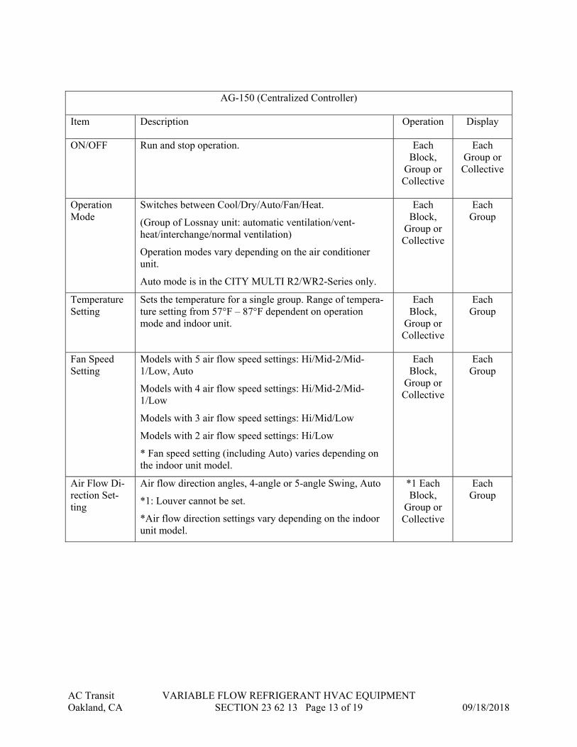
AC Transit VARIABLE FLOW REFRIGERANT HVAC EQUIPMENT Oakland, CA SECTION 23 62 13 Page 13 of 19 09/18/2018
AG-150 (Centralized Controller)
Item Description Operation Display
ON/OFF Run and stop operation. Each Block,
Group or Collective
Each Group or Collective
Operation Mode
Switches between Cool/Dry/Auto/Fan/Heat.
(Group of Lossnay unit: automatic ventilation/vent-heat/interchange/normal ventilation)
Operation modes vary depending on the air conditioner unit.
Auto mode is in the CITY MULTI R2/WR2-Series only.
Each Block,
Group or Collective
Each Group
Temperature Setting
Sets the temperature for a single group. Range of tempera-ture setting from 57°F – 87°F dependent on operation mode and indoor unit.
Each Block,
Group or Collective
Each Group
Fan Speed Setting
Models with 5 air flow speed settings: Hi/Mid-2/Mid-1/Low, Auto
Models with 4 air flow speed settings: Hi/Mid-2/Mid-1/Low
Models with 3 air flow speed settings: Hi/Mid/Low
Models with 2 air flow speed settings: Hi/Low
* Fan speed setting (including Auto) varies depending on the indoor unit model.
Each Block,
Group or Collective
Each Group
Air Flow Di-rection Set-ting
Air flow direction angles, 4-angle or 5-angle Swing, Auto
*1: Louver cannot be set.
*Air flow direction settings vary depending on the indoor unit model.
*1 Each Block,
Group or Collective
Each Group

AC Transit VARIABLE FLOW REFRIGERANT HVAC EQUIPMENT Oakland, CA SECTION 23 62 13 Page 14 of 19 09/18/2018
AG-150 (Centralized Controller)
Item Description Operation Display
Schedule Op-eration
Annual/weekly/today schedule can be set for each group of air conditioning units. Optimized startup setting is also available.
*2: The system follows either the current day, annual schedule, or weekly, which are in the descending order of overriding priority.
Twenty-four events can scheduled per day, including ON/OFF, Mode, Temperature Setting, Operation Prohibi-tion. Vane Direction, and Fan Speed.
Two types of weekly schedule(Summer/Winter) can be set.
Settable items depend on the functions that a given air con-ditioning unit supports.
*2 Each Block,
Group or Collective
Each Group
Optimized Startup
Unit starts 5 - 60 minutes before the scheduled time based on the operation data history in order to reach the scheduled temperature at the scheduled time.
Each Block,
Group or Collective
Each Block,
Group or Collective
Night Setback Setting
The function helps keep the indoor temperature in the tem-perature range while the units are
stopped and during the time this function is effective.
Each Group
Each Group
Permit / Pro-hibit Local Operation
Individually prohibit operation of each local remote control function (Start/Stop, Change operation mode, Set tempera-ture, Reset filter).
*3: Centrally Controlled is displayed on the remote con-troller for prohibited functions.
Each Block,
Group or Collective
*3 Each Group
Indoor Unit Intake Temp
Measures the intake temperature of the indoor unit when the indoor unit is operating.
N/A Each Group
Error When an error is currently occurring on an air conditioner unit, the afflicted unit and the error code are displayed
*4 When an error occurs, the LED flashes. The operation monitor screen shows the abnormal unit by flashing it. The error monitor screen shows the abnormal unit address, er-ror code and source of detection. The error log monitor screen shows the time and date, the abnormal unit address, error code and source of detection
N/A *4 Each Unit or
Collective

AC Transit VARIABLE FLOW REFRIGERANT HVAC EQUIPMENT Oakland, CA SECTION 23 62 13 Page 15 of 19 09/18/2018
AG-150 (Centralized Controller)
Item Description Operation Display
Ventilation Equipment
This interlocked system settings can be performed by the master system controller.
When setting the interlocked system, use the ventilation switch the free plan LOSSNAY settings between “Hi”, “Low” and “Stop”.
When setting a group of only free plan LOSSNAY units, you can switch between “Normal ventilation”, “Inter-change ventilation” and “Automatic ventilation”.
Each Group
Each Group
Interlock Operation of indoor groups or general equipment can be interlocked by the change of state (ON/OFF, mode, error of indoor groups/general equipment). (GB-50 will execute interlocking control depending on the interlocked setting.)
N/A N/A
External In-put / Output
By using accessory cables you can set and monitor the fol-lowing.
Input
By level: “Batch start/stop”, “Batch emergency stop”
By pulse: “batch start/stop”, “Enable/disable remote con-troller”
Output: “start/stop”, “error/Normal”
Requires the external I/O cables (PAC-YG10HA-E) :5٭sold separately.
*5 Collec-tive
*5 Collec-tive
Free Contact Interlock Control
Operation of indoor groups, general equipment or free con-tact outputs based on group(s) conditions or free contact(s) input states.
Each Group,
Output or Collective
N/A
All AG-150 Centralized Controllers shall be equipped with one RJ-45 Ethernet port to sup-port interconnection with a network PC via a closed/direct Local Area Network (LAN).
The AG-150 Centralized Controller shall be capable of performing initial settings via the 9” high-resolution, backlit, color touch panel on the controller or via a PC using the AG-150 Centralized Controller’s initial setting browser.
Optional software functions shall be available so that the building manager can securely log into each AG-150 via the PC’s web browser to support operation monitoring, scheduling, er-ror email, personal browser for PCs and MACs, and online maintenance diagnostics. Addi-tional optional software functions of Tenant Billing shall be available but shall require TG-2000 Integrated System software in conjunction with AG-150 Centralized Controllers.

AC Transit VARIABLE FLOW REFRIGERANT HVAC EQUIPMENT Oakland, CA SECTION 23 62 13 Page 16 of 19 09/18/2018
2.5 Ventilation Fan System
A. General: The ERV unit shall be factory assembled, wired and run tested. Contained within the unit shall be all factory wiring, control circuit board and blowers with motors, filters, and insulated foam air guides. Each unit will have an automatic by-pass damper system for economic operation under certain conditions. The unit shall have factory installed control board with functions for local, remote, and optional control modes.
1. Unit Cabinet: a. The cabinet shall be fabricated of galvanized steel, and covered with polyurethane
foam insulation as necessary with steel mounting points securely attached
B. Blowers: 1. The unit shall be furnished with two (2) direct drive centrifugal blowers running
simultaneously supplying and extracting air at the same rate for balanced ventilation air flow.
2. The blower motors shall be a directly connected to the blower wheels and have permanently lubricated bearings.
3. The blowers and motors shall be mounted for quiet operation.
C. Heat Exchanger 1. The Lossnay® heat exchanger element shall be constructed of specially treated cellulous
fiber membrane separated by corrugated layers to allow total heat (sensible and latent) energy recovery from the exhaust air to the supply air or from the supply air to the exhaust air as determined by design conditions.
2. The Lossnay® element shall have protective filters installed at both the supply and exhaust sides with an access cover to allow easy maintenance.
D. Bypass Damper 1. The ERV shall have an automatic supply side by-pass damper to allow inbound
ventilation air to by-pass the Lossnay® energy transfer core when outside weather conditions warrant.
2. The mechanism for opening and closing the bypass damper shall be a 208V-230V synchronous electric motor through an actuator. The motor will drive a steel cable connected to an mechanical damper flap to allow fresh air to bypass the Lossnay® element.
3. Supply and return air thermistor shall control the damper and may be interlocked with a Mitsubishi Electric PZ Series LCD remote controller.
E. Filter 1. The ERV shall be equipped with factory installed air filters located at each intake face
(both supply and exhaust sides) of the Lossnay® core to clean the air and prevent clogging.
F. Mounting 1. Mounting of the Lossnay® ERV shall be as indicated in the plans and drawings. The
ERV shall not require and condensate pan or receptacle nor condensate drain or piping.

AC Transit VARIABLE FLOW REFRIGERANT HVAC EQUIPMENT Oakland, CA SECTION 23 62 13 Page 17 of 19 09/18/2018
Mounting may be horizontal or vertical and the unit may be inverted as required by ductwork connection.
G. Electrical 1. The units will require a 208-230Volt, 1 Phase, 60Hz power supply.
H. Control 1. A 30vdc fuzzy logic signal generated by a City Multi System via a 2 conductor non polar
shielded, jacketed control wire to a PZ-52SF-E Mitsubishi LCD remote controller or interlocked with a City Multi indoor unit.
ALTERNATE:
A PZ-41SLB-E Mitsubishi LCD independent remote controller wired to TM2 on the in-ternal PCB of the Lossnay® via a 2 conductor non polar control wire. The ERV unit may be interlocked with a Mr Slim A control indoor unit via a 2 conductor non polar shielded, jacketed control wire.
ALTERNATE:
Independent control by contact closure from other sensor driven controllers, switch, or timers.
I. Performance: 1. The ERV units shall have the following nominal capacities:
Model Number Nominal Airflow External Static Capacity (in. H2O) at Nominal Airflow – Max. Speed
LGH-F300RX3-E 300 CFM 0.65”
2. The temperature recovery efficiency at high fan speed will be as follows: Model Number Temperature Recovery Enthalpic Recovery
Heating Cooling
LGH-F300RX3-E 74% 69% 52%
Performance Certified to ARI Standard 1060
3. ERV operating sound level shall not exceed the following levels at maximum fan speed:
Model Number Sound Lever Db(A) under center of unit At air outlet flange
LGH-F300RX3-E 36 44

AC Transit VARIABLE FLOW REFRIGERANT HVAC EQUIPMENT Oakland, CA SECTION 23 62 13 Page 18 of 19 09/18/2018
PART 3 - EXECUTION
3.1 GENERAL INSTALLATION
A. Coordinate equipment installation with work at walls, ceilings and various trades as necessary for proper interfacing and installation.
B. Insure that all equipment is wired properly, with correct motor rotation and positive electrical grounding.
C. Verify that adequate clearance around equipment and adjacent walls, windows and surfaces is available to permit proper maintenance and repairs.
D. Contractor shall not store tools, parts and/or debris inside equipment enclosures during the course of work.
3.2 EQUIPMENT START UP
A. Coordinate with other trades and work, including facilities management, automatic temperature controls, ductwork, general construction, roof decking and piping as necessary to interface installation of Citymulti equipment with other work.
B. Install equipment in accordance with manufacturer’s written installation instructions.
C. Ductwork Connections: 1. See Sections 23 31 13 for ductwork connection.
D. Piping connections: 1. See Section 23 23 00 for refrigerant piping.
3.3 MOUNTING AND ALIGNMENT
A. Mount equipment level. Fan coils shall be level to insure proper condensate collection.
3.4 INSPECTION
A. Verify that adequate clearance around unit and adjacent walls, windows, structure and surfaces is available to permit proper maintenance and repairs.
3.5 TESTING AND ADJUSTING
A. Start, test and run all equipment and controls in accordance with manufacturer’s written installation instructions.
AC Transit VARIABLE FLOW REFRIGERANT HVAC EQUIPMENT Oakland, CA SECTION 23 62 13 Page 19 of 19 09/18/2018
3.6 Ventilation Fan System
A. Ductwork: 1. The installer shall supply, install, test and commission all interconnecting ductwork for
the Lossnay® ERV units. 2. Ductwork sizing, layout, fittings, etc. shall be in strict accordance with the design
requirements. 3. The two outdoor ducts must be covered with heat insulating material in order to prevent
condensation from forming. 4. The two outdoor ducts must be tilted at a gradient (1/30 or more) down toward the
outdoor area from Lossnay® unit.
B. Installation 1. The installation of all Lossnay® units, duct work, all interconnecting control and power
wiring, commissioning and testing shall be carried out by licensed installers in accord with all Codes and requirements.
END OF SECTION 23 62 13

AC Transit PACKAGED, DIRECT-FIRED, OUTDOOR, HEATING-ONLY MAKEUP-AIR UNITS Oakland, CA SECTION 23 74 23 Page 1 of 10 09/18/2018
SECTION 23 74 23
PACKAGED, DIRECT-FIRED, OUTDOOR, HEATING-VENTILATION UNITS
PART 1 - GENERAL
1.1 RELATED DOCUMENTS
A. Drawings and general provisions of the Contract, including General and Supplementary Conditions and Division 01 Specification Sections, apply to this Section.
1.2 SUMMARY
A. Section includes direct-fired heating and ventilating units.
1.3 DEFINITIONS
A. BAS: Building automation system.
1.4 ACTION SUBMITTALS
A. Product Data: For each type and configuration of outdoor, direct-fired heating and ventilating unit.
1. Include rated capacities, operating characteristics, electrical characteristics, and furnished specialties and accessories.
1.5 INFORMATIONAL SUBMITTALS
A. Startup service reports.
B. Sample Warranty: For manufacturer's special warranty.
C. Seismic Qualification Certificates: For outdoor, direct-fired heating and ventilating units, accessories, and components, from manufacturer.
1. Basis for Certification: Indicate whether withstand certification is based on actual test of assembled components or on calculation.
2. Dimensioned Outline Drawings of Equipment Unit: Identify center of gravity and locate and describe mounting and anchorage provisions.
3. Detailed description of equipment anchorage devices on which the certification is based and their installation requirements.

AC Transit PACKAGED, DIRECT-FIRED, OUTDOOR, HEATING-ONLY MAKEUP-AIR UNITS Oakland, CA SECTION 23 74 23 Page 2 of 10 09/18/2018
1.6 CLOSEOUT SUBMITTALS
A. Operation and Maintenance Data: For direct-fired heating and ventilating units to include in emergency, operation, and maintenance manuals.
1.7 MAINTENANCE MATERIAL SUBMITTALS
A. Furnish extra materials that match products installed and that are packaged with protective covering for storage and identified with labels describing contents.
1. Filters: One set(s) for each unit. 2. Fan Belts: One set(s) for each unit.
1.8 WARRANTY
A. Special Warranty: Manufacturer agrees to repair or replace components of direct-fired heating and ventilating units that fail in materials or workmanship within specified warranty period.
1. Warranty Period for Heat Exchangers: Manufacturer's standard, but not less than 10 years from date of Substantial Completion.
PART 2 - PRODUCTS
2.1 MANUFACTURERS
A. Manufacturers: Subject to compliance with requirements, provide products by the following:
B. Basis-of-Design Product: Subject to compliance with requirements, provide product indicated on Drawings or comparable product by one of the following: 1. Reznor/Thomas & Betts Corporation. 2. Sterling HVAC Products.
2.2 SYSTEM DESCRIPTION
A. Factory-assembled, prewired, self-contained unit consisting of cabinet, supply fan, controls, filters, and direct-fired gas burner to be installed exterior to the building.
B. Electrical Components, Devices, and Accessories: Listed and labeled as defined in NFPA 70, by a qualified testing agency, and marked for intended location and application.
2.3 UNIT CASINGS
A. General Fabrication Requirements for Casings:
1. Forming: Form walls, roofs, and floors with at least two breaks at each joint.
AC Transit PACKAGED, DIRECT-FIRED, OUTDOOR, HEATING-ONLY MAKEUP-AIR UNITS Oakland, CA SECTION 23 74 23 Page 3 of 10 09/18/2018
2. Casing Joints: Sheet metal screws or pop rivets, factory sealed with water-resistant sealant.
3. Factory Finish for Steel and Galvanized-Steel Casings: Apply manufacturer's standard primer immediately after cleaning and pretreating.
4. Factory Finish for Steel and Galvanized-Steel Casings: Immediately after cleaning and pretreating, apply manufacturer's standard two-coat, baked-on enamel finish, consisting of prime coat and thermosetting topcoat.
5. Air-Handling-Unit Mounting Frame: Formed galvanized-steel channel or structural channel supports, designed for low deflection, welded with integral lifting lugs.
a. Seismic Fabrication Requirements: Fabricate mounting base and attachment to air-handling-unit sections, accessories, and components with reinforcement strong enough to withstand seismic forces defined in Section 23 05 48 "Vibration and Seismic Controls for HVAC" when air-handling-unit frame is anchored to building structure.
6. Airstream Surfaces: Surfaces in contact with the airstream shall comply with requirements in ASHRAE 62.1.
B. Configuration: Horizontal unit with horizontal discharge for concrete-base installation.
C. Cabinet: Galvanized-steel panels, formed to ensure rigidity and supported by galvanized-steel channels or structural channel supports with lifting lugs. Duct flanges at inlet and outlet. Pitched roof panels and knockouts with grommet seals for electrical and piping connections and lifting lugs.
D. Outer Casing: 0.0598-inch- thick steel with heat-resistant, baked-enamel.
E. Inner Casing:
1. Burner Section Inner Casing: 0.0299-inch- thick steel. 2. Double-wall casing with inner wall of solid steel:
a. Blower section. b. Filter section. c. Mixing box. d. Inlet plenum. e. Discharge plenum. f. Access Doors: Piano hinged with cam-lock fasteners for burner and fan motor
assemblies on both sides of unit.
3. Internal Insulation: Fibrous-glass duct lining, neoprene coated, comply with ASTM C 1071, Type II, applied on complete unit.
a. Thickness: 1 inch. b. Insulation Adhesive: Comply with ASTM C 916, Type I. c. Density: 1.5 lb/cu. ft.. d. Mechanical Fasteners: Galvanized steel suitable for adhesive, mechanical, or
welding attachment to casing without damaging liner when applied as recommended by manufacturer and without causing air leakage.

AC Transit PACKAGED, DIRECT-FIRED, OUTDOOR, HEATING-ONLY MAKEUP-AIR UNITS Oakland, CA SECTION 23 74 23 Page 4 of 10 09/18/2018
F. Discharge Section:
1. Galvanized-steel assembly with gravity parallel-blade dampers with nylon bushings.
a. Pattern: Single deflection. b. Leakage: Standard leakage.
G. Inspection and Access Panels and Access Doors:
1. Panel and Door Fabrication: Formed and reinforced, single- or double-wall and insulated panels of same materials and thicknesses as casing.
2. Inspection and Access Panels:
a. Fasteners: Two or more camlock type for panel lift-out operation. Arrangement shall allow panels to be opened against air-pressure differential.
b. Gasket: Neoprene, applied around entire perimeters of panel frames. c. Size: Large enough to allow inspection and maintenance of air-handling unit's
internal components.
3. Access Doors:
a. Hinges: A minimum of two ball-bearing hinges or stainless-steel piano hinge and two wedge-lever-type latches, operable from inside and outside. Arrange doors to be opened against air-pressure differential.
b. Gasket: Neoprene, applied around entire perimeters of panel frames.
4. Locations and Applications:
a. Fan Section: Doors. b. Access Section: Doors. c. Coil Section: Inspection and access panels. d. Damper Section: Doors. e. Filter Section: Doors large enough to allow periodic removal and installation of
filters. f. Mixing Section: Doors.
5. Service Light: 100-W vaporproof fixture with switched junction box located inside adjacent to door.
a. Locations: Each section accessed with door.
2.4 OUTDOOR-AIR INTAKE HOOD
A. Type: Manufacturer's standard hood or louver.
B. Materials: Match cabinet.
C. Bird Screen: Comply with requirements in ASHRAE 62.1.
D. Filter: Aluminum, 2 inches cleanable.

AC Transit PACKAGED, DIRECT-FIRED, OUTDOOR, HEATING-ONLY MAKEUP-AIR UNITS Oakland, CA SECTION 23 74 23 Page 5 of 10 09/18/2018
E. Configuration: Designed to inhibit wind-driven rain and snow from entering unit.
2.5 SUPPLY-AIR FAN
A. Fan Type: Centrifugal, rated according to AMCA 210; statically and dynamically balanced, galvanized steel; mounted on solid-steel shaft with heavy-duty, self-aligning, permanently lubricated ball bearings. Bearing rating: L10 of 60,000 hours.
B. Drive: V-belt drive with matching fan pulley and adjustable motor sheaves and belt assembly.
C. Mounting: Fan wheel, motor, and drives shall be mounted in fan casing with spring isolators.
D. Fan-Shaft Lubrication Lines: Extended to a location outside the casing.
2.6 DAMPERS
A. Outdoor-Air Damper: Galvanized-steel, opposed-blade dampers with vinyl blade seals and stainless-steel jamb seals, having a maximum leakage of 10 cfm/sq. ft. of damper area, at a differential pressure of 2-inch wg.
B. Damper Operator: Direct coupled, electronic with spring return or fully modulating as required by the control sequence.
2.7 DIRECT-FIRED GAS BURNER
A. Description: Factory assembled, piped, and wired; and complying with ANSI Z21.47, "Gas-Fired Central Furnaces," and with NFPA 54, "National Fuel Gas Code."
1. CSA Approval: Designed and certified by and bearing label of CSA. 2. Burners: Aluminized steel with stainless-steel inserts.
a. Gas Control Valve: Single stage. b. Fuel: Natural gas. c. Minimum Combustion Efficiency: 90 percent. d. Ignition: Electronically controlled electric spark with flame sensor.
B. Safety Controls:
1. Vent Flow Verification: Differential pressure switch to verify open vent. 2. Control Transformer: 24-V ac. 3. High Limit: Thermal switch or fuse to stop burner. 4. Gas Train: Regulated, redundant, 24-V ac gas valve assembly containing pilot solenoid
valve, electronic-modulating temperature control valve, pilot filter, pressure regulator, pilot shutoff, and manual shutoff all in one body.
5. Purge-period timer shall automatically delay burner ignition and bypass low-limit control.
6. Gas Manifold: Safety switches and controls complying with ANSI standards. 7. Airflow Proving Switch: Differential pressure switch senses correct airflow before
energizing pilot.

AC Transit PACKAGED, DIRECT-FIRED, OUTDOOR, HEATING-ONLY MAKEUP-AIR UNITS Oakland, CA SECTION 23 74 23 Page 6 of 10 09/18/2018
8. Automatic-Reset, High-Limit Control Device: Stops burner and closes main gas valve if high-limit temperature is exceeded.
9. Safety Lockout Switch: Locks out ignition sequence if burner fails to light after three tries. Controls are reset manually by turning the unit off and on.
2.8 UNIT CONTROL PANEL
A. Factory-wired, fuse-protected control transformer, connection for power supply and field-wired unit to remote control panel.
B. Control Panel: Surface-mounted remote panel, with engraved plastic cover and the following lights and switches:
1. On-off-auto fan switch. 2. Heat-vent-off switch. 3. Supply-fan operation indicating light. 4. Heating operation indicating light. 5. Thermostat. 6. Damper position potentiometer. 7. Dirty-filter indicating light operated by unit-mounted differential pressure switch. 8. Safety-lockout indicating light. 9. Enclosure: NEMA 250, Type 1.
2.9 CONTROLS
A. Control Devices:
1. Remote Thermostat: Adjustable room thermostat with temperature readout. 2. Remote Setback Thermostat: Adjustable room thermostat without temperature readout. 3. Static-Pressure Transmitter: Nondirectional sensor with suitable range for expected input,
and temperature compensated. 4. Fire-Protection Thermostats: Fixed or adjustable settings to operate at not less than 75
deg F above normal maximum operating temperature. 5. Timers: Seven-day, programming-switch timer with synchronous-timing motor and
seven-day dial; continuously charged, nickel-cadmium-battery-driven, eight-hour, power-failure carryover; multiple-switch trippers; minimum of two and maximum of eight signals per day with two normally open and two normally closed output contacts.
6. Timers: Solid-state, programmable time control with four separate programs; 24-hour battery carryover; individual on-off-auto switches for each program; 365-day calendar with 20 programmable holidays; choice of fail-safe operation for each program; and system fault alarm.
7. Ionization-Type Smoke Detectors: 24-V dc, nominal; self-restoring; plug-in arrangement; integral visual-indicating light; sensitivity that can be tested and adjusted in place after installation; integral addressable module; remote controllability; responsive to both visible and invisible products of combustion; self-compensating for changes in environmental conditions.
B. Fan Control: Interlock fan to start with exhaust fan(s) to which this heating and ventilating unit is associated for makeup air.
AC Transit PACKAGED, DIRECT-FIRED, OUTDOOR, HEATING-ONLY MAKEUP-AIR UNITS Oakland, CA SECTION 23 74 23 Page 7 of 10 09/18/2018
C. Fan Control: Timer starts and stops direct-fired heating and ventilating unit and exhaust fan(s).
1. Smoke detectors, located in supply air, shall stop fans when the presence of smoke is detected.
D. Outdoor-Air Damper Control, 100 Percent Outdoor-Air Units: Outdoor-air damper shall open when supply fan starts, and close when fan stops.
E. Outdoor Air Damper Control: When fan is running, outdoor- and return-air dampers shall modulate to supply minimum outdoor air as follows:
1. Minimum 100 percent outdoor air.
F. Temperature Control: Operates gas valve to maintain supply-air temperature.
1. Operates gas valve to maintain discharge-air temperature with factory-mounted sensor in blower outlet.
2. Operates gas valve to maintain space temperature with wall-mounting, field-wired sensor. 3. Timer shall select remote setback thermostat to maintain space temperature at 50 deg F. 4. Burner Control: Two or four steps of control using one or two burner sections in series. 5. Burner Control: 20 to 100 percent modulation of the firing rate. 10 to 100 percent with
dual burner units.
G. BAS Interface: Factory-installed hardware and software to enable the BAS to monitor, control, and display status and alarms of heating and ventilating unit.
1. Hardwired Points:
a. Room temperature. b. Discharge-air temperature. c. Burner operating.
2.10 CAPACITIES AND CHARACTERISTICS
A. Refer to drawings:
PART 3 - EXECUTION
3.1 EXAMINATION
A. Examine areas and conditions, with Installer present, for compliance with requirements for installation tolerances and other conditions affecting performance of the Work.
B. Examine roughing-in for piping, ducts, and electrical systems to verify actual locations of piping and electrical connections before equipment installation.
C. Verify cleanliness of airflow path to include inner-casing surfaces, filters, coils, turning vanes, fan wheels, and other components.

AC Transit PACKAGED, DIRECT-FIRED, OUTDOOR, HEATING-ONLY MAKEUP-AIR UNITS Oakland, CA SECTION 23 74 23 Page 8 of 10 09/18/2018
D. Proceed with installation only after unsatisfactory conditions have been corrected.
3.2 INSTALLATION
A. Equipment Mounting:
1. Install heating and ventilating unit on cast-in-place concrete equipment base(s). Comply with requirements for equipment bases and foundations specified in Section 03 30 53 "Miscellaneous Cast-in-Place Concrete."
2. Comply with requirements for vibration isolation and seismic control devices specified in Section 23 05 48 "Vibration and Seismic Controls for HVAC."
3. Comply with requirements for vibration isolation devices specified in Section 23 05 48 "Vibration Controls for HVAC."
B. Unit Support: Install heating and ventilating unit level on structural curbs. Coordinate wall penetrations and flashing with wall construction. Secure units to structural support with anchor bolts.
C. Install gas-fired units according to NFPA 54, "National Fuel Gas Code."
D. Install controls and equipment shipped by manufacturer for field installation with direct-fired heating and ventilating units.
3.3 CONNECTIONS
A. Drawings indicate general arrangement of piping, fittings, and specialties.
1. Gas Piping: Comply with requirements in Section 23 11 23 "Facility Natural-Gas Piping." Connect gas piping with shutoff valve and union, and with sufficient clearance for burner removal and service. Make final connections of gas piping to unit with corrugated, stainless-steel tubing flexible connectors complying with ANSI LC 1/CSA 6.26 equipment connections.
B. Duct Connections: Connect supply ducts to direct-fired heating and ventilating units with flexible duct connectors. Comply with requirements in Section 23 33 00 "Air Duct Accessories" for flexible duct connectors.
C. Ground equipment according to 26 05 00 “Electrical Basic Materials and Methods”.
D. Connect wiring according to Section 26 05 00 “Electrical Basic Materials and Methods”.
3.4 FIELD QUALITY CONTROL
A. Manufacturer's Field Service: Engage a factory-authorized service representative to test and inspect components, assemblies, and equipment installations, including connections.
B. Perform tests and inspections with the assistance of a factory-authorized service representative.
C. Units will be considered defective if they do not pass tests and inspections.

AC Transit PACKAGED, DIRECT-FIRED, OUTDOOR, HEATING-ONLY MAKEUP-AIR UNITS Oakland, CA SECTION 23 74 23 Page 9 of 10 09/18/2018
D. Prepare test and inspection reports.
3.5 STARTUP SERVICE
A. Engage a factory-authorized service representative to perform startup service.
B. Complete installation and startup checks according to manufacturer's written instructions and perform the following:
1. Inspect for visible damage to burner combustion chamber. 2. Inspect casing insulation for integrity, moisture content, and adhesion. 3. Verify that clearances have been provided for servicing. 4. Verify that controls are connected and operable. 5. Verify that filters are installed. 6. Purge gas line. 7. Inspect and adjust vibration isolators. 8. Verify bearing lubrication. 9. Inspect fan-wheel rotation for movement in correct direction without vibration and
binding. 10. Adjust fan belts to proper alignment and tension.
C. Start unit according to manufacturer's written instructions.
1. Complete startup sheets and attach copy with Contractor's startup report. 2. Inspect and record performance of interlocks and protective devices; verify sequences. 3. Operate unit for run-in period recommended by manufacturer. 4. Perform the following operations for both minimum and maximum firing, and adjust
burner for peak efficiency:
a. Measure gas pressure at manifold. b. Measure combustion-air temperature at inlet to combustion chamber. c. Measure supply-air temperature and volume when burner is at maximum firing
rate and when burner is off. Calculate useful heat to supply air.
5. Calibrate thermostats. 6. Adjust and inspect high-temperature limits. 7. Inspect dampers, if any, for proper stroke and interlock with return-air dampers. 8. Inspect controls for correct sequencing of heating, mixing dampers, refrigeration, and
normal and emergency shutdown. 9. Measure and record airflow. Plot fan volumes on fan curve. 10. Verify operation of remote panel, including pilot-operation and failure modes. Inspect the
following:
a. High-limit heat. b. Alarms.
11. After startup and performance testing, change filters, verify bearing lubrication, and adjust belt tension.
12. Verify drain-pan performance. 13. Verify outdoor-air damper operation.

AC Transit PACKAGED, DIRECT-FIRED, OUTDOOR, HEATING-ONLY MAKEUP-AIR UNITS Oakland, CA SECTION 23 74 23 Page 10 of 10 09/18/2018
3.6 ADJUSTING
A. Adjust initial temperature set points.
B. Set field-adjustable switches and circuit-breaker trip ranges as indicated.
C. Occupancy Adjustments: When requested within 12 months from date of Substantial Completion, provide on-site assistance in adjusting system to suit actual occupied conditions. Provide up to two visits to Project during other-than-normal occupancy hours for this purpose.
END OF SECTION 23 74 23

AC Transit ELECTRICAL BASIC MATERIALS AND METHODS Oakland, CA SECTION 26 05 00 Page 1 of 12 09/18/2018
SECTION 26 05 00
ELECTRICAL BASIC MATERIALS AND METHODS
PART 1 - GENERAL
1.1 SECTION INCLUDES:
A. Conduit, raceways and fittings. B. Wires and Cables for 600 Volts and less. C. Wire connections and devices. D. Outlet boxes. E. Pull and junction boxes. F. Disconnect Switches and Fuses G. Supporting Devices. H. Identifying Devices. I. Grounding and Bonding
1.2 SUBMITTALS
A. Submit in accordance with the requirements of Division 1 the following items: B. A list of conduit types indicating where each type of conduit will be used. Indicate conduit
manufacturers and fittings to be used. C. Wires and Cables. D. Wiring Devices and Plates E. Nameplates, including engraving schedules where engraved plates are specified. F. Fused disconnect switches.
1.3 DRAWINGS:
A. The drawings are diagrammatic and show the general extent and arrangement of the work required which shall be followed as closely as the actual construction site conditions and work of the other trades will permit.
1.4 QUALITY ASSURANCE
A. Products: Listed and classified by Underwriters Laboratories, Inc. as suitable for the purpose specified and indicated.
B. Coordination of the work: Contractor shall become familiar with the conditions of the job site, and with the landscape drawings, drawings of other disciplines and specifications and plan the installation of the electrical work to conform with that shown and specified so as to provide the best possible assembly of the combined work of the trades.

AC Transit ELECTRICAL BASIC MATERIALS AND METHODS Oakland, CA SECTION 26 05 00 Page 2 of 12 09/18/2018
1.5 REFERENCES
A. ANSI C80.1 - Rigid Steel Conduit, Zinc Coated. B. ANSI C80.3 - Electrical Metallic Tubing, Zinc Coated. C. ANSI C80.5 - Rigid Aluminum Conduit. D. NECA (INST) - Standard of Installation; National Electrical Contractors Association. E. NEMA FB 1 - Fittings, Cast Metal Boxes, and Conduit Bodies for Conduit and Cable
Assemblies. F. NFPA 70 - National Electrical Code - latest edition.
1.6 Provide as-built reproducible drawings showing all outlets with circuit numbers at each outlet and maintenance manuals for all new equipment.
1.7 Warranties for labor and materials - 1 year from the date of final acceptance of the work.
1.8 In addition to material and equipment specified, also provide all incidental materials required to effect complete installation. Such incidental materials include solders, tapes, caulking, mastics, gaskets, etc.
1.9 The Contractor will be held responsible to have examined the site and premises and satisfied himself as to existing conditions under which he will be obligated to operate in performing his part of the work or that which will in any manner affect the work under this contract.
1.10 Provide wiring tests upon completion of work and make adjustments as necessary for satisfactory operation of system.
PART 2 - PRODUCTS
2.1 MATERIALS AND EQUIPMENT – GENERAL
A. Materials and equipment shall be new, current models of manufacturers, Bare complete identification by manufacturer and Bare UL labels where applicable.
2.2 CONDUIT, RACEWAYS AND FITTINGS
A. Rigid Steel Conduit 1. Rigid steel conduit shall be full weight, pipe size, finished inside and out by hot-dip
galvanizing after fabrication, and shall conform with ANSI C80.1 and UL. 2. Couplings shall be electroplated steel, compression type. 3. Insulating Bushings: Threaded polypropylene or thermo-setting phenolic rated 150°C
minimum. 4. Insulated grounding Bushings: Threaded cast malleable iron body with insulated throat
and steel "lay-in" ground lug with compression screw.

AC Transit ELECTRICAL BASIC MATERIALS AND METHODS Oakland, CA SECTION 26 05 00 Page 3 of 12 09/18/2018
5. Insulated Metallic Bushings: Threaded cast malleable iron body with plastic insulated throat rated 150°C.
6. Running threads are not acceptable.
B. Non-Metallic Conduit 1. Schedule 40 PVC underground is an acceptable conduit material.
2.3 CONDUITS AND FITTINGS
A. Rigid galvanized steel or IMC shall be galvanized. Coupling and connectors shall be galvanized or cadmium plated; Allied Tube and Conduit, Triangle, or equal.
B. Conduit Fittings: Provide watertight compression type conduit fittings for electrical metallic tubing installed in wet location. Fittings for rigid galvanized steel or IMC shall be threaded.
2.4 CONDUCTORS
A. Conductors for within dwelling unit and garage shall be NM cable complying with NEC Article 334.
B. Conductors for exterior shall be soft drawn, annealed copper wire 98% conductivity bearing UL label.
C. Insulation: Provide the following (600 volt): D. Type THW, XHHW insulated wire for conductors #2 or larger E. Type THHN/THWN for all wire smaller than #2 F. Manufacturers: Southwire, Anaconda, Rome, General Cable, Cerro Wire, or equal.
2.5 WIRE CONNECTION
A. Wire Joints: Wires in sizes from #18 to #8 AWG, stranded conductor, with insulation rated 105 degrees C. or less shall be joined with electrical spring connectors of three part construction incorporating a non-restricted, zinc coated steel spring enclosed in a steel shell with an outer jacket of vinyl plastic with a flexible insulating skirt.
B. Mechanical Compression Connectors and Taps: Stranded conductors from #6 AWG to 750 Kcmil shall be joined or tapped using bolted pressure connectors having cast bronze compression bolts. Fittings shall be wide range-taking and designed to facilitate the making of parallel taps, tees, crosses or end-to-end connections. Split-bolt connectors will not be acceptable.
C. Fixture Connections: Splice fixture wire to circuit wiring with solderless connectors as specified above in paragraph A.
D. Terminating Lugs: Conductors from size No. 6 AWG to 750 MCM, copper, shall be terminated using tin plated hydraulically operated crimping tools and dies as stipulated by the lug manufacturer. Lugs shall be 3M "Scotchlok" series 30014, Burndy Type Ya-L series, or equal.
E. Splicing and Insulating Tape (600 volts and below): General purpose electrical tape shall be suitable for temperatures from minus 18 degrees C to 105 degrees C, shall be black, ultraviolet proof, self-extinguishing, 7 mil thick vinyl with a dielectric strength of 10,000 volts. Apply 4 layers half-lap with 2” over-lay on each conductor.
F. Insulating Putty (600 volts and below): Pads or rolls of non-corrosive, self-fusing, one eight inch thick rubber putty with PVC backing sheet. Putty shall be suitable for temperatures from

AC Transit ELECTRICAL BASIC MATERIALS AND METHODS Oakland, CA SECTION 26 05 00 Page 4 of 12 09/18/2018
minus 17.8 degrees C to 37.8 degrees C and shall have a dielectric strength of 570 volts/mil minimum.
G. Insulating Resin: Two Part liquid epoxy resin with resin and catalyst in pre measured, sealed mixing pouch. Resin shall have a set up time of approximately 30 minutes at 21.1 degrees C, and shall have thermal and dielectric properties equal to the insulation properties of the cables immersed in the resin.
H. Terminal Strip Connectors: Terminate wire in locking tongue style, pressure type, solderless lug where applicable.
I. Wire Connectors: J. #6 AWG and larger: Thomas and Betts "Lock-Tite", Burndey, "Quicklug" or OZ Type
PT/PTC. K. #8 AWG and smaller: Scotch spring steel with insulated cap, Thomas and Betts, "STA-KON
Piggy" with insulator or ideal, wire nut or wing nut type.
2.6 OUTLET BOXES
A. Standard outlet boxes: Galvanized, die formed or drawn steel, knock-out type of size and configuration best suited to the application indicated on the plans. Minimum box size, 4 inch square by 1-1/2 inch deep, indoor use. FS cast boxes are required for outdoor use.
B. Cast Metal Outlet Boxes: FS cast boxes are required for outdoor use. Four-inch round, galvanized cast iron alloy with threaded hubs and mounting lugs as required. Boxes shall be furnished with cast cover plates of the same material as the box and neoprene cover gaskets. Thomas and Betts, Crouse-Hinds VXF series, Appleton JBX series or equal.
C. Conduit Outlet Bodies: Cadmium plated, cast iron alloy. Obround conduit outlet bodies with threaded conduit hubs and neoprene gasketed, cast iron covers. Outlet bodies shall be used to facilitate pulling of conductors or to make changes in conduit direction only. Splices are not permitted in conduit outlet bodies. Thomas and Betts, Crouse Hinds Form 8 Condulets, Appleton form 35 Unilets, or equal.
D. Wiring Devices: E. Duplex Receptacles: 20A, 125V, 3 wire, grounded, NEMA 5-15R, tamper resistant, Pass &
Seymour S885TRWCC14 decorator style or equal. F. GFI Receptacles: 20A, 125V, 3 wire, Nema 5-15R, tamper resistant, Pass & Seymour
S1595NTLTRWCC8 or equal. G. Outdoor Receptacles: shall be 20A, 125V, 3-wire, Nema 5-15R, Pass & Seymour
S1595TRWCC8 with while in use cover or equal. H. Switches: Lighting switches shall be 20A, 3 wire. Shall be Pass & Seymour 2601-W decorator
style or equal. 3-way switch shall be Pass & Seymour 2603-W or equal. I. Dimmer Switches: Dimmer have full-on bypass mode. Shall be Pass & Seymour 91180-W
decorator style or equal. 3-way dimmer switch shall be Pass & Seymour 91183-W or equal.
2.7 PULL AND JUNCTION
A. Sheet Metal Boxes: Use standard outlet or concrete ring boxes wherever possible; otherwise use minimum 15 gauge get metal, NEMA 1 boxes, sized to code requirements with covers secured by cadmium plated machine screws located 6 inches on centers. Circle AW Products, Hoffman Engineering Co., or equal.
B. Cast Metal Boxes: Use standard cast malleable iron outlet or device boxes wherever possible; otherwise use cadmium plated, cast malleable iron junction boxes with bolt-on, interchangeable

AC Transit ELECTRICAL BASIC MATERIALS AND METHODS Oakland, CA SECTION 26 05 00 Page 5 of 12 09/18/2018
conduit hub plates with neoprene gaskets. Appleton RS series; Crouse Hinds RS series, or equal.
2.8 DISCONNECTS:
A. Small Motors and Water Heaters: Provide 30A, 600V AC rated double-pole toggle switch for equipment disconnects. Switch shall be rated for 2HP motors at 120V and 5HP motors at 240V. Toggle switch shall be horsepower rated. Device shall have silver cadmium oxide contacts. Device shall be fully enclosed. Device shall have quick make, slow break design. Device shall be listed as a manual motor controller. Device shall be Bryant 30002B for interior installation and Bryant 30302B for exterior installations or equal.
B. Large Motors: Provide switches rated from 30A to 60A. Switches shall have switch blades which are visible when the switch is OFF and the cover is open The switch operating mechanism shall be quick-make, quick-break such that, during normal operation of the switch, the operation of the contacts shall not be capable of being restrained by the operating handle after the closing or opening action of the contacts has started. The operating handle shall be an integral part of the box, not the cover. Switch enclosures shall be rated Nema 3R for exterior installations. Switches shall be Square D – Class 3130 or equal.
2.9 DISCONNECT SWITCHES
A. All disconnect switches shall be heavy-duty type and have the number of poles, voltage rating, and horsepower rating as required by the motor or equipment. Disconnect switches shall be in enclosures to suit conditions, NEMA 3R for outdoor and NEMA 1 for indoor. Disconnect switches shall be fused unless otherwise noted on the drawings. As manufactured by: Square D - Class 3110, ITE Seimens, or equal.
2.10 FUSES
A. Dual Element, Time Delay, UL Class RK5. Rejection type. Size and Voltage as indicated on equipment. Bussman, Little Fuse, or approved equal.
2.11 ELECTRICAL SUPPORTING DEVICES
A. Concrete Fasteners: Phillips "Red-Head" or equal, self drilling expansion type concrete anchor. B. Conduit Straps: Hot-dip galvanized, cast malleable iron, two hole type strap with cast clamp-
backs and spacers as required. OZ/Gedney No. 14-50G strap and #141G spacer; Efcor No. 231 strap, and No.131 spacer; or equal.
C. Construction Channel: 1-1/2 inch by 1-1/2 inch 12 gauge galvanized steel channel with 17/32 inch diameter bolt holes, 1-1/2 inch on center, in the base of the channel. Kindorf 905 series, Unistrut P-1000-HS or equal.
D. Cable Ties and Clamps: Thomas and Betts Co. "Ty-Raps" Panduit "Pan-Ty" or equal one piece, nylon, reusable type lashing ties.
E. Fasteners (General) : Wood screws for fastening to wood. Machine screws for fastening to steel. Toggle bolts for fastening to hollow concrete block, gypsum board, or plaster walls. Expansion anchors for attachments to pre-poured concrete.

AC Transit ELECTRICAL BASIC MATERIALS AND METHODS Oakland, CA SECTION 26 05 00 Page 6 of 12 09/18/2018
2.12 IDENTIFYING DEVICES
A. Nameplates: Type NP: Engraved black bakelite, 1 inch by 3-1/2 inch, 1/8 inch high white letters, machine screw retained. For permanent identification of all switchboards, panelboards, circuit breakers in separate enclosures, motor starters, relays, time switches, disconnect switches and other cabinet-enclosed apparatus including terminal cabinets or match existing as closely as possible.
B. Legend Plates: Type LP: Die-stamped metal legend plate with mounting hole and positioning key for attachment to panel mounted operators' devices. Engraved paint-filled characters as specified.
C. Wire & Terminal Markers: Self-adhering, pre-printed vinyl with self-laminating wrap around strip. Markers shall be legible after termination. Brady B191 series, Thomas & Betts WSL series or equal.
D. Conductor Phase Markers: Thomas & Betts WCPHAS series or similar in addition to colored marking as specified under this section of the specifications.
2.13 GROUNDING AND BONDING
A. Ground Rods B. Manufacturer: Blackburn, Erico, or approved Equal C. Size: 3/4" x 10' Ground Rods D. Grounding Electrode Conductor, 2/0 for foundation foots, and per NEC. E. Grounding Well - Christy Box, Valve Box
PART 3 - EXECUTION
3.1 GENERAL
A. General: Exact locations of distances and devices shall be taken from field measurements and approved by the architect prior to rough in.
B. Provide all wiring connections for equipment furnished under other sections of the contract documents.
3.2 CONDUIT AND RACEWAY APPLICATIONS
A. Rigid Steel Conduit: For all exterior applications, all conduits larger than 2” trade diameter, indoor, below eight (8) feet.
B. Electrical Metallic Tubing (EMT): Interior only and above eight (8) feet or when entering a panel from above.
C. Liquidtight Flexible Metallic Conduit: In damp and wet locations for connections to motors, transformers, vibrating equipment and machinery. Connections to all pump motors, flow switches, and similar devices.
D. Rigid Galvanized: Install for all underground and exterior runs. Minimum conduit size shall be ¾”.

AC Transit ELECTRICAL BASIC MATERIALS AND METHODS Oakland, CA SECTION 26 05 00 Page 7 of 12 09/18/2018
3.3 WIRE
A. Wire Sizes: Provide no wire smaller than #12 for lighting, receptacles or other circuits. Provide stranded wire for wire larger than #10.
B. Wiring for two circuits in bedrooms can be Southwire NM-B 2/2 or equal. C. Wires installed in exterior locations shall be THWN. NM-B conductors shall not be installed in
exterior locations. D. NM-B conductors shall be installed in interior locations only.
3.4 CONDUIT INSTALLATION
A. General 1. All conduit runs shown on the plans are sized based on the use of rigid steel conduit and
THWN copper conductors. If conductor type is changed the contractor shall be responsible for resizing conduits to meet code. In no case is conduit to be sized smaller than 3/4" trade diameter.
2. Low voltage wiring shall be installed in conduit, minimum 3/4" trade diameter. 3. Conduits shall be tightly covered and well protected during construction using metallic
bushings and bushing "pennies" to seal open ends. 4. In making joints in rigid steel conduit, ream conduit smooth after cutting and threading. 5. Clean any conduit in which moisture or any foreign matter has collected before pulling in
conductors. Paint all field threaded joints to prevent corrosion. 6. In all empty conduits or ducts, install an 1100 pound tensile strength polyethylene pulling
rope. 7. Conduit systems shall be electrically continuous throughout. Install code size,
uninsulated, copper grounding conductors in all conduit runs, grounding conductor shall be bonded to conduit, equipment frames and properly grounded.
B. Layout: 1. All new conduits shall be concealed. Any field conditions that does not allow
concealment of conduits shall be reviewed with the Architect prior to rough-in. 2. Locations of conduit runs shall be planned in advance of the installation and coordinated
with concrete work, plumbing and framing. 3. Where practical install conduits in groups in parallel vertical or horizontal runs and at
elevations that avoid unnecessary off-sets. 4. Low voltage conduit shall be grouped separately and labelled every 10 ft interval as to
system (i.e. fire, control, etc) 5. Exposed conduit shall be run parallel or at right angles to the centerlines of the columns
and beams. 6. Conduits shall not be placed closer than 12 inches from a parallel hot water or steam line
or three inches from such lines crossing perpendicular to the runs. 7. In long runs of conduit, provide sufficient pull boxes per NEC inside buildings to
facilitate pulling wires and cables. Support pull boxes from structure independent of conduit supports. These pull boxes are not shown on the plans.
C. Supports: 1. All raceway systems shall be secured to building structures using specified fasteners,
clamps and hangers spaced according to Code. 2. Support single runs of conduit using two hole pipe straps. Where run horizontally on
walls in damp or wet locations, install "clamp blocks" to space conduit off the surface.

AC Transit ELECTRICAL BASIC MATERIALS AND METHODS Oakland, CA SECTION 26 05 00 Page 8 of 12 09/18/2018
3. Multiple conduit runs shall be supported using "trapeze" hangers fabricated from 3/8 inch diameter, threaded steel rods secured to building structures. Fasten conduit to construction channel with standard two hole pipe clamps. Provide lateral seismic bracing for hangers.
4. Installation 5. Locate and install anchors, fasteners, and supports in accordance with NECA "Standard
of Installation". 6. Do not fasten supports to pipes, ducts, mechanical equipment, or conduit. 7. Do not drill or cut structural members. 8. Rigidly weld support members or use hexagon-head bolts to present neat appearance with
adequate strength and rigidity. Use spring lock washers under all nuts. 9. Install surface-mounted cabinets and panelboards with minimum of four anchors. 10. In wet and damp locations use steel channel supports to stand cabinets and panelboards 1
inch (25 mm) off wall. 11. Use sheet metal channel to bridge studs above and below cabinets and panelboards
recessed in hollow partitions.
D. Terminations and Joints 1. Raceways shall be joined using specified couplings or transition couplings where
dissimilar raceway systems are joined. 2. Rigid conduit connection to enclosures shall be made by Myers type grounding hubs
only. EMT connections to enclosures shall be made with compression connector with grounding lock-nuts or bushings.
3. Conduit terminations exposed at weatherproof enclosures and cast outlet boxes shall be made watertight using appropriate connectors and hubs. Install expansion couplings where any conduit crosses a building separation or expansion joint
4. Install cable sealing bushings on all conduits originating outside the building walls and terminating in switchgear, cabinets or gutters inside the building. Install cable sealing bushings or caulk conduit terminations in all grade level or below grade exterior pull, junction or outlet boxes.
E. Penetrations: 1. Furnish and install metal sleeves for all exposed interior conduit runs passing through
concrete floors or walls. Following conduit installation, seal all penetrations using non-iron bearing, chloride free, non-shrinking, dry-pack, grouting compound.
2. Install specified watertight conduit entrance seals and membrane clamps at all below grade wall and floor penetrations. Conduits penetrating exterior building walls and building floor slab shall be insulated rigid steel.
3. Conduits penetrating rated walls, floors, etc. shall be fireproofed.
3.5 WIRING DEVICES
A. Receptacles: 1. General Areas: General provisions for receptacles shall comply with NEC Article
210.52.A.1-2. 2. Kitchen Areas: Receptacles shall be provided in compliance with NEC Article 210.52.B
and 210.52.C. 3. Restrooms: Receptacles shall be provided in compliance with NEC Article 210.52.D.

AC Transit ELECTRICAL BASIC MATERIALS AND METHODS Oakland, CA SECTION 26 05 00 Page 9 of 12 09/18/2018
4. Family room, dining room, living room, dens, bedrooms, sunrooms, closets and hallways shall have devices that are Arc Fault Circuit-Interrupter (AFCI) protected or have breakers that are AFCI rated per NEC article 210.12.
B. Switches: 1. Controls for lighting shall comply with 2005 Title 24 Residential Compliance Manual.
3.6 CABLE AND WIRE INSTALLATION
A. Examination 1. Verify that interior of building has been protected from weather. 2. Verify that mechanical work likely to damage wire and cable has been completed. 3. Verify that raceway installation is complete and supported. 4. Verify that field measurements are as indicated.
B. Preparation 1. In existing conduits that will be reused, pull out existing conductors. 2. Completely and thoroughly swab raceway before installing wire. 3. Use 50/50 solution of Simple Green. Use CO2 to blow water and soap into conduit - let
soak to break up dried out pulling compounds, then pull conductors. Pull one conductor at a time if will not pull all out together.
C. General: 1. Conductors shall not be in conduit until all work of any nature that may cause injury is
completed. Care should be taken in pulling conductors that insulation is not damaged. U.L. approved non-petroleum base and insulating type pulling compound shall be used as needed.
2. All cables shall be installed and tested in accordance with manufacturer's requirements and warranty.
3. Block and tackle, power driven winch or other mechanical means shall not be used in pulling conductors of size smaller than AWG # 1.
D. Splicing and Terminating: 1. All aspects of splicing and terminating shall be in accordance with cable manufacturer's
published procedures. 2. Make up all splices in outlet boxes with connectors as specified herein with separate tails
of correct color to be made up to splice. Provide at least six (6) inches of tails packed in box after splice is made up.
3. All wire and cable in panels, control centers and equipment enclosures shall be bundled and clamped.
4. Encapsulate splices in exterior outlet, junction and pull boxes using insulating resin kits. All splices for exterior equipment in pump rooms shall be made up watertight.
5. Insulate mechanical compression taps AWG # 1/0 and larger using pre-molded, snap-on insulating boots or specified conformable insulating putty overwrapped with two half-lapped layers of insulating tape.
E. Identification:

AC Transit ELECTRICAL BASIC MATERIALS AND METHODS Oakland, CA SECTION 26 05 00 Page 10 of 12 09/18/2018
1. Securely tag all branch circuits, noting the purpose of each. Mark conductors with vinyl wrap-around markers. Where more than two conductors run through a single outlet, mark each circuit with the corresponding circuit number at the panelboard.
2. Color code conductors size #6 and larger using specified phase color markers and identification tags.
3. All terminal strips are to have each individual terminal identified with specified vinyl markers.
4. All identification shall be legible and readable after completion of installation.
3.7 ELECTRICAL CONNECTIONS
A. Make electrical connections in accordance with equipment manufacturer's instructions. B. Make conduit connections to equipment using flexible conduit. Use liquid tight flexible conduit
with watertight connectors in damp or wet locations. C. Connect heat producing equipment using wire and cable with insulation suitable for
temperatures encountered. D. Provide receptacle outlet to accommodate connection with attachment plug. E. Provide cord and cap where field-supplied attachment plug is required. F. Install suitable strain-relief clamps and fittings for cord connections at outlet boxes and
equipment connection boxes. G. Install disconnect switches, controllers, control stations, and control devices to complete
equipment wiring requirements. H. Install terminal block jumpers to complete equipment wiring requirements. I. Install interconnecting conduit and wiring between devices and equipment to complete
equipment wiring requirements.
3.8 INSTALLATION OF BOXES
A. General: 1. Leave no un-used openings in any box. Install close-up plugs as required to seal
openings. 2. Exposed outlet boxes and boxes in damp or wet locations shall be cast metal with
gasketed cast metal cover plates.
B. Box Layout: 1. Outlet boxes shall be installed at the locations and elevations shown on the drawings or
specified herein. Make adjustments to locations as required by structural conditions and to suit coordination requirements of other trades.
2. Install junction or pullboxes where required to limit bends in conduit runs to not more than 360 degrees or where pulling tension achieved would exceed the maximum allowable for the cable to be installed. Consult wire and cable manufacturer.
3.9 INSTALLATION OF WIRING DEVICES
A. General 1. Install all devices flush mounted unless otherwise noted on the drawings. Comply with
layout drawings for general locations. Consult Architect or Owner for locations that have

AC Transit ELECTRICAL BASIC MATERIALS AND METHODS Oakland, CA SECTION 26 05 00 Page 11 of 12 09/18/2018
conflict with other devices or manner not suitable for installation. Avoid place devices behind open doors.
2. Align devices horizontally and vertically. Device plates shall be aligned vertically with tolerance of 1/16". All four edges of device plates shall be in contact with the wall surface.
3. Mounting height as indicated on the drawings and according to ADA requirements. 4. Install device plates on all outlet boxes. Provide blank plates for all empty, spare, and
boxes for future use. 5. Securely fasten devices into boxes and attach appropriate cover plates. 6. Caulk around edges or outdoor device plates and boxes when rough wall surfaces prevent
raintight seal. Use caulking materials approved by Architect/Engineer. 7. Fireproof around opening of devices located or penetrating firerated construction
assemblies.
B. Identification 1. Label all outlets and switches. Mark each wiring device where circuits and panel supply
is derived from. 2. All identification shall be legible and readable after completion of installation.
3.10 INSTALLATION OF FUSES AND DISCONNECT SWITCHES
A. Fuses shall be installed where noted on plans. Sizes are based on design data provided by air conditioning mfg. Listed or labeled equipment must be in accordance with instructions included in the listing or labeling. Be sure to observe maximum branch circuit fuse size labels.
B. Disconnect switches shall be mounted on the units. Coordinate with mechanical contractor to ensure switches are not mounted on a removable access panel.
C. Label each disconnect fuse with equipment tag as indicated in the single line diagram, or as directed.
3.11 ELECTRICAL EQUIPMENT GROUNDING
A. Ground non-current carrying metal parts of electrical equipment enclosures, frames, conductor raceways or cable trays to provide a low impedance path for line-to-ground fault current and to bond all non-current carrying metal parts together. Install a ground conductor in each raceway system in addition to conductors shown. Equipment ground conductor shall be electrically and mechanically continuous from the electrical circuit source to the equipment to be grounded. Size ground conductors per NEC 250 unless larger conductors are shown on the drawings.
B. Grounding conductors shall be identified with green insulation, except where a bare ground conductor is specified. Where green insulation is not available, on larger sizes, black insulation shall be used and suitably identified with green tape at each junction box or device enclosure.
C. Install metal raceway couplings, fittings and terminations secure and tight to insure good ground continuity. Provide insulated grounding bushing and bonding jumper where metal raceway is not directly attached to equipment metal enclosure and at concentric knock-outs.
D. Motors shall be connected to equipment ground conductors with a conduit grounding bushing and with a bolted solderless lug connection on the metal frame.
E. Conduit terminating in concentric knockouts at panelboards, cabinets and gutters shall have insulated grounding bushings and bonding jumpers installed interconnecting all such conduits and the panelboard cabinet, gutter, etc.
F. Performance: Measure ground resistance, 25 Ohms or less.

AC Transit ELECTRICAL BASIC MATERIALS AND METHODS Oakland, CA SECTION 26 05 00 Page 12 of 12 09/18/2018
3.12 BONDING
A. Bonding shall be provided to assure electrical continuity and the capacity to conduct safely any fault current likely to be imposed.
B. Bonding shall be in accordance with NEC Article 250, Part V
3.13 WORKMANSHIP
A. Preparation, handling, and installation shall be in accordance with manufacturer's written instructions and technical data particular to the product specified and/or accepted equal except as otherwise specified. Coordinate work and cooperate with others in furnishing and placing this work. Work to reviewed shop drawings for work done by others and to field measurements as necessary to properly fit the work.
B. Conform to the National Electrical Contractor's Association "Standard of Installation" for general installation practice.
3.14 INSTALLATION
A. Install in accordance with manufacturer's instructions.
END OF SECTION 26 05 00
AC Transit LOW-VOLTAGE DISTRIBUTION TRANSFORMERS 9/18/2018 Oakland, CA SECTION 26 22 13 Page 1 of 7
SECTION 26 22 13 LOW-VOLTAGE DISTRIBUTION TRANSFORMERS
PART 1 - GENERAL
1.1 RELATED DOCUMENTS
A. Drawings and general provisions of the Contract, including General and Supplementary Conditions and Division 01 Specification Sections, apply to this Section.
1.2 SUMMARY
A. Section includes distribution, dry-type transformers with a nominal primary and secondary rating of 600 V and less, with capacities up to 1500 kVA.
1.3 ACTION SUBMITTALS
A. Product Data: For each type of product.
1. Include construction details, material descriptions, dimensions of individual components and profiles, and finishes for each type and size of transformer.
2. Include rated nameplate data, capacities, weights, dimensions, minimum clearances, installed devices and features, and performance for each type and size of transformer.
B. Shop Drawings:
1. Detail equipment assemblies and indicate dimensions, weights, loads, required clearances, method of field assembly, components, and location and size of each field connection.
2. Vibration Isolation Base Details: Detail fabrication including anchorages and attachments to structure and to supported equipment.
3. Include diagrams for power, signal, and control wiring.
1.4 INFORMATIONAL SUBMITTALS
A. Seismic Qualification Data: Certificates, for transformers, accessories, and components, from manufacturer.
1. Basis for Certification: Indicate whether withstand certification is based on actual test of assembled components or on calculation.
2. Dimensioned Outline Drawings of Equipment Unit: Identify center of gravity and locate and describe mounting and anchorage provisions.
3. Detailed description of equipment anchorage devices on which the certification is based and their installation requirements.
4. Certification: Indicate that equipment meets Project seismic requirements.

AC Transit LOW-VOLTAGE DISTRIBUTION TRANSFORMERS 9/18/2018 Oakland, CA SECTION 26 22 13 Page 2 of 7
1.5 CLOSEOUT SUBMITTALS
A. Operation and Maintenance Data: For transformers to include in emergency, operation, and maintenance manuals.
1.6 QUALITY ASSURANCE
A. Testing Agency Qualifications: Accredited by NETA.
1. Testing Agency's Field Supervisor: Certified by NETA to supervise on-site testing.
1.7 DELIVERY, STORAGE, AND HANDLING
A. Inspection: On receipt, inspect for and note any shipping damage to packaging and transformer.
1. If manufacturer packaging is removed for inspection, and transformer will be stored after inspection, re-package transformer using original or new packaging materials that provide protection equivalent to manufacturer's packaging.
B. Storage: Store in a warm, dry, and temperature-stable location in original shipping packaging.
C. Handling: Follow manufacturer's instructions for lifting and transporting transformers.
PART 2 - PRODUCTS
2.1 MANUFACTURERS
A. Manufacturers: Subject to compliance with requirements, provide products by one of the following:
1. Eaton. 2. General Electric Company. 3. Square D; by Schneider Electric.
2.2 PERFORMANCE REQUIREMENTS
A. Seismic Performance: Transformers shall withstand the effects of earthquake motions determined according to ASCE/SEI 7.
1. The term "withstand" means "the transformer will remain in place without separation of any parts when subjected to the seismic forces specified."
2.3 GENERAL TRANSFORMER REQUIREMENTS
A. Description: Factory-assembled and -tested, air-cooled units for 60-Hz service.

AC Transit LOW-VOLTAGE DISTRIBUTION TRANSFORMERS 9/18/2018 Oakland, CA SECTION 26 22 13 Page 3 of 7
B. Comply with NFPA 70.
1. Electrical Components, Devices, and Accessories: Listed and labeled as defined in NFPA 70, by a qualified testing agency, and marked for intended location and use.
C. Transformers Rated 15 kVA and Larger:
1. Comply with 10 CFR 431 (DOE 2016) efficiency levels. 2. Marked as compliant with DOE 2016 efficiency levels by an NRTL.
D. Shipping Restraints: Paint or otherwise color-code bolts, wedges, blocks, and other restraints that are to be removed after installation and before energizing. Use fluorescent colors that are easily identifiable inside the transformer enclosure.
2.4 DISTRIBUTION TRANSFORMERS
A. Comply with NFPA 70.
B. Cores: Electrical grade, non-aging silicon steel with high permeability and low hysteresis losses.
1. One leg per phase. 2. Core volume shall allow efficient transformer operation at 10 percent above the nominal
tap voltage. 3. Grounded to enclosure.
C. Coils: Continuous windings except for taps.
1. Coil Material: Copper. 2. Internal Coil Connections: Brazed or pressure type. 3. Terminal Connections: Welded.
D. Encapsulation: Transformers smaller than 30 kVA shall have core and coils completely resin encapsulated.
E. Enclosure: Ventilated.
1. NEMA 250,: Core and coil shall be encapsulated within resin compound to seal out moisture and air.
2. KVA Ratings: Based on convection cooling only and not relying on auxiliary fans. 3. Wiring Compartment: Sized for conduit entry and wiring installation. 4. Finish: Comply with NEMA 250.
a. Finish Color: Gray weather-resistant enamel.
F. Taps for Transformers 25 kVA and Larger: Two 2.5 percent taps above and two 2.5 percent taps below normal full capacity.
G. Insulation Class, Smaller Than 30 kVA: 180 deg C, UL-component-recognized insulation system with a maximum of 115 deg C rise above 40 deg C ambient temperature.

AC Transit LOW-VOLTAGE DISTRIBUTION TRANSFORMERS 9/18/2018 Oakland, CA SECTION 26 22 13 Page 4 of 7
H. Insulation Class, 30 kVA and Larger: 220 deg C, UL-component-recognized insulation system with a maximum of 115 deg C rise above 40 deg C ambient temperature.
I. Grounding: Provide ground-bar kit or a ground bar installed on the inside of the transformer enclosure.
J. Neutral: Rated 200 percent of full load current for K-factor-rated transformers.
K. Wall Brackets: Manufacturer's standard brackets of Wall brackets fabricated from design drawings signed and sealed by a licensed structural engineer.
2.5 IDENTIFICATION
A. Nameplates: Engraved, laminated-acrylic or melamine plastic signs for each distribution transformer, mounted with corrosion-resistant screws. Nameplates and label products are specified in Section 26 05 00. Confirm labeling with architect.
2.6 SOURCE QUALITY CONTROL
A. Test and inspect transformers according to IEEE C57.12.01 and IEEE C57.12.91.
1. Resistance measurements of all windings at rated voltage connections and at all tap connections.
2. Ratio tests at rated voltage connections and at all tap connections. 3. Phase relation and polarity tests at rated voltage connections. 4. No load losses, and excitation current and rated voltage at rated voltage connections. 5. Impedance and load losses at rated current and rated frequency at rated voltage
connections. 6. Applied and induced tensile tests. 7. Regulation and efficiency at rated load and voltage. 8. Insulation-Resistance Tests:
a. High-voltage to ground. b. Low-voltage to ground. c. High-voltage to low-voltage.
9. Temperature tests.
PART 3 - EXECUTION
3.1 EXAMINATION
A. Examine conditions for compliance with enclosure- and ambient-temperature requirements for each transformer.
B. Verify that field measurements are as needed to maintain working clearances required by NFPA 70 and manufacturer's written instructions.

AC Transit LOW-VOLTAGE DISTRIBUTION TRANSFORMERS 9/18/2018 Oakland, CA SECTION 26 22 13 Page 5 of 7
C. Examine walls, floors, roofs, and concrete bases for suitable mounting conditions where transformers will be installed.
D. Verify that ground connections are in place and requirements in Section 26 05 00 "Electrical Basic Materials And Methods" have been met. Maximum ground resistance shall be 5 ohms at location of transformer.
E. Proceed with installation only after unsatisfactory conditions have been corrected.
3.2 INSTALLATION
A. Install wall-mounted transformers level and plumb with wall brackets fabricated by transformer manufacturer.
1. Coordinate installation of wall-mounted and structure-hanging supports with actual transformer provided.
2. Brace wall-mounted transformers as noted by structural.
B. Install transformers level and plumb on a concrete base with vibration-dampening supports. Locate transformers away from corners and not parallel to adjacent wall surface.
C. Secure covers to enclosure and tighten all bolts to manufacturer-recommended torques to reduce noise generation.
D. Remove shipping bolts, blocking, and wedges.
3.3 CONNECTIONS
A. Ground equipment according to Section 26 0500.
B. Connect wiring according to Section 26 05 00 "Electrical Basic Materials And Methods"
C. Tighten electrical connectors and terminals according to manufacturer's published torque-tightening values. If manufacturer's torque values are not indicated, use those specified in UL 486A-486B.
D. Provide flexible connections at all conduit and conductor terminations and supports to eliminate sound and vibration transmission to the building structure.
3.4 FIELD QUALITY CONTROL
A. Manufacturer's Field Service: Engage a factory-authorized service representative to test and inspect components, assemblies, and equipment installations, including connections.
B. Perform tests and inspections with the assistance of a factory-authorized service representative.
C. Small (Up to 167-kVA Single-Phase or 500-kVA Three-Phase) Dry-Type Transformer Field Tests:

AC Transit LOW-VOLTAGE DISTRIBUTION TRANSFORMERS 9/18/2018 Oakland, CA SECTION 26 22 13 Page 6 of 7
1. Visual and Mechanical Inspection.
a. Inspect physical and mechanical condition. b. Inspect anchorage, alignment, and grounding. c. Verify that resilient mounts are free and that any shipping brackets have been
removed. d. Verify the unit is clean. e. Perform specific inspections and mechanical tests recommended by manufacturer. f. Verify that as-left tap connections are as specified. g. Verify the presence of surge arresters and that their ratings are as specified.
2. Electrical Tests:
a. Measure resistance at each winding, tap, and bolted connection. b. Perform insulation-resistance tests winding-to-winding and each winding-to-
ground. Apply voltage according to manufacturer's published data. In the absence of manufacturer's published data, comply with NETA ATS, Table 100.5. Calculate polarization index: the value of the index shall not be less than 1.0.
c. Perform turns-ratio tests at all tap positions. Test results shall not deviate by more than one-half percent from either the adjacent coils or the calculated ratio. If test fails, replace the transformer.
d. Verify correct secondary voltage, phase-to-phase and phase-to-neutral, after energization and prior to loading.
D. Large (Larger Than 167-kVA Single Phase or 500-kVA Three Phase) Dry-Type Transformer Field Tests:
1. Visual and Mechanical Inspection:
a. Inspect physical and mechanical condition. b. Inspect anchorage, alignment, and grounding. c. Verify that resilient mounts are free and that any shipping brackets have been
removed. d. Verify the unit is clean. e. Perform specific inspections and mechanical tests recommended by manufacturer. f. Verify that as-left tap connections are as specified. g. Verify the presence of surge arresters and that their ratings are as specified.
2. Electrical Tests:
a. Measure resistance at each winding, tap, and bolted connection. b. Perform insulation-resistance tests winding-to-winding and each winding-to-
ground. Apply voltage according to manufacturer's published data. In the absence of manufacturer's published data, comply with NETA ATS, Table 100.5. Calculate polarization index: the value of the index shall not be less than 1.0.
c. Perform power-factor or dissipation-factor tests on all windings. d. Perform turns-ratio tests at all tap positions. Test results shall not deviate by more
than one-half percent from either the adjacent coils or the calculated ratio. If test fails, replace the transformer.
e. Perform an excitation-current test on each phase.

AC Transit LOW-VOLTAGE DISTRIBUTION TRANSFORMERS 9/18/2018 Oakland, CA SECTION 26 22 13 Page 7 of 7
f. Perform an applied voltage test on all high- and low-voltage windings to ground. See IEEE C57.12.91, Sections 10.2 and 10.9.
g. Verify correct secondary voltage, phase-to-phase and phase-to-neutral, after energization and prior to loading.
E. Remove and replace units that do not pass tests or inspections and retest as specified above.
F. Test Labeling: On completion of satisfactory testing of each unit, attach a dated and signed "Satisfactory Test" label to tested component.
3.5 ADJUSTING
A. Record transformer secondary voltage at each unit for at least 48 hours of typical occupancy period. Adjust transformer taps to provide optimum voltage conditions at secondary terminals. Optimum is defined as not exceeding nameplate voltage plus 5 percent and not being lower than nameplate voltage minus 3 percent at maximum load conditions. Submit recording and tap settings as test results.
B. Output Settings Report: Prepare a written report recording output voltages and tap settings.
3.6 CLEANING
A. Vacuum dirt and debris; do not use compressed air to assist in cleaning.
END OF SECTION

AC Transit PANELBOARDS Oakland, CA SECTION 26 24 16 Page 1 of 11 09/18/2018
SECTION 26 24 16
PANELBOARDS
PART 1 - GENERAL
1.1 RELATED DOCUMENTS
A. Drawings and general provisions of the Contract, including General and Supplementary Conditions and Division 01 Specification Sections, apply to this Section.
1.2 SUMMARY
A. Section Includes:
1. Distribution panelboards. 2. Lighting and appliance branch-circuit panelboards.
1.3 DEFINITIONS
A. SVR: Suppressed voltage rating.
B. TVSS: Transient voltage surge suppressor.
1.4 PERFORMANCE REQUIREMENTS
A. Seismic Performance: Panelboards shall withstand the effects of earthquake motions determined according to SEI/ASCE 7.
1. The term "withstand" means "the unit will remain in place without separation of any parts from the device when subjected to the seismic forces specified and the unit will be fully operational after the seismic event."
1.5 ACTION SUBMITTALS
A. Product Data: For each type of panelboard, switching and overcurrent protective device, transient voltage suppression device, accessory, and component indicated. Include dimensions and manufacturers' technical data on features, performance, electrical characteristics, ratings, and finishes.
B. Shop Drawings: For each panelboard and related equipment.
1. Include dimensioned plans, elevations, sections, and details. Show tabulations of installed devices, equipment features, and ratings.
2. Detail enclosure types and details for types other than NEMA 250, Type 1.

AC Transit PANELBOARDS Oakland, CA SECTION 26 24 16 Page 2 of 11 09/18/2018
3. Detail bus configuration, current, and voltage ratings. 4. Short-circuit current rating of panelboards and overcurrent protective devices. 5. Include evidence of NRTL listing for series rating of installed devices. 6. Detail features, characteristics, ratings, and factory settings of individual overcurrent
protective devices and auxiliary components. 7. Include wiring diagrams for power, signal, and control wiring. 8. Include time-current coordination curves for each type and rating of overcurrent
protective device included in panelboards. Submit on translucent log-log graft paper; include selectable ranges for each type of overcurrent protective device.
1.6 INFORMATIONAL SUBMITTALS
A. Qualification Data: For qualified testing agency.
B. Seismic Qualification Certificates: Submit certification that panelboards, overcurrent protective devices, accessories, and components will withstand seismic forces and include the following:
1. Basis for Certification: Indicate whether withstand certification is based on actual test of assembled components or on calculation.
2. Dimensioned Outline Drawings of Equipment Unit: Identify center of gravity and locate and describe mounting and anchorage provisions.
3. Detailed description of equipment anchorage devices on which the certification is based and their installation requirements.
C. Field Quality-Control Reports:
1. Test procedures used. 2. Test results that comply with requirements. 3. Results of failed tests and corrective action taken to achieve test results that comply with
requirements.
D. Panelboard Schedules: For installation in panelboards submit final printed versions after load balancing.
1.7 CLOSEOUT SUBMITTALS
A. Operation and Maintenance Data: For panelboards and components to include in emergency, operation, and maintenance manuals and include the following:
1. Manufacturer's written instructions for testing and adjusting overcurrent protective devices.
2. Time-current curves, including selectable ranges for each type of overcurrent protective device that allows adjustments.
1.8 MAINTENANCE MATERIAL SUBMITTALS
A. Furnish extra materials that match products installed and that are packaged with protective covering for storage and identified with labels describing contents.

AC Transit PANELBOARDS Oakland, CA SECTION 26 24 16 Page 3 of 11 09/18/2018
1. Keys: Two spares for each type of panelboard cabinet lock. 2. Circuit Breakers Including GFCI and Ground Fault Equipment Protection (GFEP) Types:
Two spares for each panelboard. 3. Fuses for Fused Switches: Equal to 10 percent of quantity installed for each size and
type, but no fewer than three of each size and type. 4. Fuses for Fused Power-Circuit Devices: Equal to 10 percent of quantity installed for
each size and type, but no fewer than three of each size and type.
1.9 QUALITY ASSURANCE
A. Testing Agency Qualifications: Member company of NETA or an NRTL.
1. Testing Agency's Field Supervisor: Currently certified by NETA to supervise on-site testing.
B. Source Limitations: Obtain panelboards, overcurrent protective devices, components, and accessories from single source from single manufacturer.
C. Product Selection for Restricted Space: Drawings indicate maximum dimensions for panelboards including clearances between panelboards and adjacent surfaces and other items. Comply with indicated maximum dimensions.
D. Electrical Components, Devices, and Accessories: Listed and labeled as defined in NFPA 70, by a qualified testing agency, and marked for intended location and application.
E. Comply with NEMA PB 1.
F. Comply with NFPA 70.
1.10 DELIVERY, STORAGE, AND HANDLING
A. Remove loose packing and flammable materials from inside panelboards; install temporary electric heating (250 W per panelboard) to prevent condensation.
B. Handle and prepare panelboards for installation according to NECA 407.
1.11 PROJECT CONDITIONS
A. Environmental Limitations:
1. Do not deliver or install panelboards until spaces are enclosed and weathertight, wet work in spaces is complete and dry, work above panelboards is complete, and temporary HVAC system is operating and maintaining ambient temperature and humidity conditions at occupancy levels during the remainder of the construction period.
2. Rate equipment for continuous operation under the following conditions unless otherwise indicated:
a. Ambient Temperature: Not exceeding minus 22 deg F to plus 104 deg F. b. Altitude: Not exceeding 6600 feet.

AC Transit PANELBOARDS Oakland, CA SECTION 26 24 16 Page 4 of 11 09/18/2018
B. Service Conditions: NEMA PB 1, usual service conditions, as follows:
1. Ambient temperatures within limits specified. 2. Altitude not exceeding 6600 feet.
C. Interruption of Existing Electric Service: Do not interrupt electric service to facilities occupied by Owner or others unless permitted under the following conditions and then only after arranging to provide temporary electric service according to requirements indicated:
1. Notify Construction Manager no fewer than two days in advance of proposed interruption of electric service.
2. Do not proceed with interruption of electric service without Owner's written permission. 3. Comply with NFPA 70E.
1.12 COORDINATION
A. Coordinate layout and installation of panelboards and components with other construction that penetrates walls or is supported by them, including electrical and other types of equipment, raceways, piping, encumbrances to workspace clearance requirements, and adjacent surfaces. Maintain required workspace clearances and required clearances for equipment access doors and panels.
B. Coordinate sizes and locations of concrete bases with actual equipment provided. Cast anchor-bolt inserts into bases. Concrete, reinforcement, and formwork requirements are specified with concrete.
1.13 WARRANTY
A. Special Warranty: Manufacturer's standard form in which manufacturer agrees to repair or replace transient voltage suppression devices that fail in materials or workmanship within specified warranty period.
1. Warranty Period: Five years from date of Substantial Completion.
PART 2 - PRODUCTS
2.1 GENERAL REQUIREMENTS FOR PANELBOARDS
A. Fabricate and test panelboards according to IEEE 344 to withstand seismic forces.
B. Enclosures: Flush- and surface-mounted cabinets.
1. Rated for environmental conditions at installed location.
a. Indoor Dry and Clean Locations: NEMA 250, Type 1. b. Outdoor Locations: NEMA 250, Type 3R.

AC Transit PANELBOARDS Oakland, CA SECTION 26 24 16 Page 5 of 11 09/18/2018
2. Front: Secured to box with concealed trim clamps. For surface-mounted fronts, match box dimensions; for flush-mounted fronts, overlap box.
3. Hinged Front Cover: Entire front trim hinged to box and with standard door within hinged trim cover.
4. Skirt for Surface-Mounted Panelboards: Same gage and finish as panelboard front with flanges for attachment to panelboard, wall, and ceiling or floor.
5. Gutter Extension and Barrier: Same gage and finish as panelboard enclosure; integral with enclosure body. Arrange to isolate individual panel sections.
6. Finishes:
a. Panels and Trim: Steel and galvanized steel, factory finished immediately after cleaning and pretreating with manufacturer's standard two-coat, baked-on finish consisting of prime coat and thermosetting topcoat.
b. Back Boxes: Same finish as panels and trim. c. Fungus Proofing: Permanent fungicidal treatment for overcurrent protective
devices and other components.
7. Directory Card: Inside panelboard door, mounted in metal frame with transparent protective cover.
C. Incoming Mains Location: Top and bottom.
D. Phase, Neutral, and Ground Buses:
1. Material: Hard-drawn copper, 98 percent conductivity. 2. Equipment Ground Bus: Adequate for feeder and branch-circuit equipment grounding
conductors; bonded to box. 3. Isolated Ground Bus: Adequate for branch-circuit isolated ground conductors; insulated
from box. 4. Extra-Capacity Neutral Bus: Neutral bus rated 200 percent of phase bus and UL listed as
suitable for nonlinear loads. 5. Split Bus: Vertical buses divided into individual vertical sections.
E. Conductor Connectors: Suitable for use with conductor material and sizes.
1. Material: Hard-drawn copper, 98 percent conductivity. 2. Main and Neutral Lugs: Compression Mechanical type. 3. Ground Lugs and Bus-Configured Terminators: Compression Mechanical type. 4. Feed-Through Lugs: Compression Mechanical type, suitable for use with conductor
material. Locate at opposite end of bus from incoming lugs or main device. 5. Subfeed (Double) Lugs: Compression Mechanical type suitable for use with conductor
material. Locate at same end of bus as incoming lugs or main device. 6. Gutter-Tap Lugs: Compression Mechanical type suitable for use with conductor
material. Locate at same end of bus as incoming lugs or main device. 7. Extra-Capacity Neutral Lugs: Rated 200 percent of phase lugs mounted on extra-
capacity neutral bus.
F. Service Equipment Label: NRTL labeled for use as service equipment for panelboards or load centers with one or more main service disconnecting and overcurrent protective devices.

AC Transit PANELBOARDS Oakland, CA SECTION 26 24 16 Page 6 of 11 09/18/2018
G. Future Devices: Mounting brackets, bus connections, filler plates, and necessary appurtenances required for future installation of devices.
H. Panelboard Short-Circuit Current Rating: Rated for series-connected system with integral or remote upstream overcurrent protective devices and labeled by an NRTL. Include size and type of allowable upstream and branch devices, listed and labeled for series-connected short-circuit rating by an NRTL.
I. Panelboard Short-Circuit Current Rating: Fully rated to interrupt symmetrical short-circuit current available at terminals.
2.2 DISTRIBUTION PANELBOARDS
A. Manufacturers: Subject to compliance with requirements, available manufacturers offering products that may be incorporated into the Work include, but are not limited to, the following:
B. Basis-of-Design Product: Subject to compliance with requirements, provide product indicated on Drawings or comparable product by one of the following:
1. General Electric Company; GE Consumer & Industrial - Electrical Distribution. 2. Square D; a brand of Schneider Electric. 3. Or approved equal.
C. Panelboards: NEMA PB 1, power and feeder distribution type.
D. Doors: Secured with vault-type latch with tumbler lock; keyed alike.
1. For doors more than 36 inches high, provide two latches, keyed alike.
E. Mains: Circuit breaker Fused switch Lugs only.
F. Branch Overcurrent Protective Devices for Circuit-Breaker Frame Sizes 125 A and Smaller: Plug-in Bolt-on circuit breakers.
G. Branch Overcurrent Protective Devices for Circuit-Breaker Frame Sizes Larger Than 125 A: Bolt-on circuit breakers; plug-in circuit breakers where individual positive-locking device requires mechanical release for removal.
H. Branch Overcurrent Protective Devices: Fused switches.
I. Contactors in Main Bus: NEMA ICS 2, Class A, electrically mechanically held, general-purpose controller, with same short-circuit interrupting rating as panelboard.
1. Internal Control-Power Source: Control-power transformer, with fused primary and secondary terminals, connected to main bus ahead of contactor connection.
2. External Control-Power Source: 120-V branch circuit.

AC Transit PANELBOARDS Oakland, CA SECTION 26 24 16 Page 7 of 11 09/18/2018
2.3 DISCONNECTING AND OVERCURRENT PROTECTIVE DEVICES
A. Manufacturers: Subject to compliance with requirements, provide products by one of the following:
B. Basis-of-Design Product: Subject to compliance with requirements, provide product indicated on Drawings or comparable product by one of the following:
1. General Electric Company; GE Consumer & Industrial - Electrical Distribution. 2. Square D; a brand of Schneider Electric. 3. Or approved equal.
C. Fused Switch: NEMA KS 1, Type HD; clips to accommodate specified fuses; lockable handle.
1. Fuses, and Spare-Fuse Cabinet: Comply with requirements specified in Section 26 05 00 “Electrical Basic Materials And Methods”.
2. Fused Switch Features and Accessories: Standard ampere ratings and number of poles. 3. Auxiliary Contacts: One Two normally open and normally closed contact(s) that operate
with switch handle operation.
2.4 PANELBOARD SUPPRESSORS
A. Manufacturers: Subject to compliance with requirements, provide products by one of the following:
B. Basis-of-Design Product: Subject to compliance with requirements, provide product indicated on Drawings or comparable product by one of the following: 1. General Electric Company; GE Consumer & Industrial - Electrical Distribution. 2. Square D; a brand of Schneider Electric. 3. Or approve equal.
C. Surge Protection Device: IEEE C62.41-compliant, integrally mounted, solid-state, parallel-connected, non-modular type, with sine-wave tracking suppression and filtering modules, UL 1449, second edition, short-circuit current rating matching or exceeding the panelboard short-circuit rating, and with the following features and accessories:
1. Accessories:
a. LED indicator lights for power and protection status. b. Audible alarm, with silencing switch, to indicate when protection has failed. c. One set of dry contacts rated at 5 A and 250-V ac, for remote monitoring of
protection status.
D. Surge Protection Device: IEEE C62.41-compliant, integrally mounted, plug-in wired-in bolt-on, solid-state, parallel-connected, modular (with field-replaceable modules) non-modular type, with sine-wave tracking suppression and filtering modules, UL 1449, second edition, short-circuit current rating matching or exceeding the panelboard short-circuit rating, and with the following features and accessories:
1. Accessories:

AC Transit PANELBOARDS Oakland, CA SECTION 26 24 16 Page 8 of 11 09/18/2018
a. Fuses rated at 200-kA interrupting capacity. b. Fabrication using bolted compression lugs for internal wiring. c. Integral disconnect switch. d. Redundant suppression circuits. e. Redundant replaceable modules. f. Arrangement with wire connections to phase buses, neutral bus, and ground bus. g. LED indicator lights for power and protection status. h. Audible alarm, with silencing switch, to indicate when protection has failed. i. Form-C contacts rated at 5 A and 250-V ac, one normally open and one normally
closed, for remote monitoring of system operation. Contacts shall reverse position on failure of any surge diversion module or on opening of any current-limiting device. Coordinate with building power monitoring and control system.
j. Four Six-digit, transient-event counter set to totalize transient surges.
2. Peak Single-Impulse Surge Current Rating: 160 kA per mode/320 kA per phase 120 kA per mode/240 kA per phase 80 kA per mode/160 kA per phase.
3. Minimum single-impulse current ratings, using 8-by-20-mic.sec. waveform described in IEEE C62.41.2.
a. Line to Neutral: 70,000 A. b. Line to Ground: 70,000 A. c. Neutral to Ground: 50,000 A.
4. Withstand Capabilities: 12,000 IEEE C62.41, Category C3 (10 kA), 8-by-20-mic.sec. surges with less than 5 percent change in clamping voltage.
5. Protection modes and UL 1449 SVR for grounded wye circuits with 480Y/277 and 208Y/120-V, three-phase, four-wire circuits shall be as follows:
a. Line to Neutral: 800 V for 480Y/277 400 V for 208Y/120,. b. Line to Ground: 800 V for 480Y/277, 400 V for 208Y/120. c. Neutral to Ground: 800 V for 480Y/277, 400 V for 208Y/120.
6. Protection modes and UL 1449 SVR for 240/120-V, single-phase, three-wire circuits shall be as follows:
a. Line to Neutral: 400 V. b. Line to Ground: 400 V. c. Neutral to Ground: 400 V.
7. Protection modes and UL 1449 SVR for 240/120-V, three-phase, four-wire circuits with high leg shall be as follows:
a. Line to Neutral: 400 V, 800 V from high leg. b. Line to Ground: 400 V. c. Neutral to Ground: 400 V.
8. Protection modes and UL 1449 SVR for 240-, 480-, or 600-V, three-phase, three-wire, delta circuits shall be as follows:
a. Line to Line: 2000 V for 480 V, 1000 V for 240 V. b. Line to Ground: 1500 V for 480 V, 800 V for 240 V.

AC Transit PANELBOARDS Oakland, CA SECTION 26 24 16 Page 9 of 11 09/18/2018
2.5 ACCESSORY COMPONENTS AND FEATURES
A. Accessory Set: Include tools and miscellaneous items required for overcurrent protective device test, inspection, maintenance, and operation.
B. Portable Test Set: For testing functions of solid-state trip devices without removing from panelboard. Include relay and meter test plugs suitable for testing panelboard meters and switchboard class relays.
PART 3 - EXECUTION
3.1 EXAMINATION
A. Receive, inspect, handle, and store panelboards according to NECA 407 NEMA PB 1.1.
B. Examine panelboards before installation. Reject panelboards that are damaged or rusted or have been subjected to water saturation.
C. Examine elements and surfaces to receive panelboards for compliance with installation tolerances and other conditions affecting performance of the Work.
D. Proceed with installation only after unsatisfactory conditions have been corrected.
3.2 INSTALLATION
A. Install panelboards and accessories according to NECA 407 NEMA PB 1.1.
B. Temporary Lifting Provisions: Remove temporary lifting eyes, channels, and brackets and temporary blocking of moving parts from panelboards.
C. Comply with mounting and anchoring requirements specified in Section 260548 "Vibration and Seismic Controls for Electrical Systems."
D. Mount top of trim 90 inches above finished floor unless otherwise indicated.
E. Mount panelboard cabinet plumb and rigid without distortion of box. Mount recessed panelboards with fronts uniformly flush with wall finish and mating with back box.
F. Install overcurrent protective devices and controllers not already factory installed.
1. Set field-adjustable, circuit-breaker trip ranges.
G. Install filler plates in unused spaces.
H. Stub four 1-inch empty conduits from panelboard into accessible ceiling space or space designated to be ceiling space in the future. Stub four 1-inch empty conduits into raised floor space or below slab not on grade.

AC Transit PANELBOARDS Oakland, CA SECTION 26 24 16 Page 10 of 11 09/18/2018
I. Arrange conductors in gutters into groups and bundle and wrap with wire ties after completing load balancing.
J. Comply with NECA 1.
3.3 IDENTIFICATION
A. Identify field-installed conductors, interconnecting wiring, and components; provide warning signs complying with authority having jurisdiction.
B. Create a directory to indicate installed circuit loads after balancing panelboard loads; incorporate Owner's final room designations. Obtain approval before installing. Use a computer or typewriter to create directory; handwritten directories are not acceptable.
C. Panelboard Nameplates: Label each panelboard with a nameplate complying with requirements for identification complying with authority having jurisdiction.
D. Device Nameplates: Label each branch circuit device in distribution panelboards with a nameplate complying with requirements for identification complying with authority having jurisdiction.
3.4 FIELD QUALITY CONTROL
A. Testing Agency: Contractor to engage a qualified testing agency to perform tests and inspections.
B. Manufacturer's Field Service: Engage a factory-authorized service representative to inspect, test, and adjust components, assemblies, and equipment installations, including connections.
C. Perform tests and inspections.
1. Manufacturer's Field Service: Engage a factory-authorized service representative to inspect components, assemblies, and equipment installations, including connections, and to assist in testing.
D. Acceptance Testing Preparation:
1. Test insulation resistance for each panelboard bus, component, connecting supply, feeder, and control circuit.
2. Test continuity of each circuit.
E. Tests and Inspections:
1. Perform each visual and mechanical inspection and electrical test stated in NETA Acceptance Testing Specification. Certify compliance with test parameters.
2. Correct malfunctioning units on-site, where possible, and retest to demonstrate compliance; otherwise, replace with new units and retest.
3. Perform the following infrared scan tests and inspections and prepare reports:

AC Transit PANELBOARDS Oakland, CA SECTION 26 24 16 Page 11 of 11 09/18/2018
a. Initial Infrared Scanning: After Substantial Completion, but not more than 60 days after Final Acceptance, perform an infrared scan of each panelboard. Remove front panels so joints and connections are accessible to portable scanner.
b. Follow-up Infrared Scanning: Perform an additional follow-up infrared scan of each panelboard 11 months after date of Substantial Completion.
c. Instruments and Equipment:
1) Use an infrared scanning device designed to measure temperature or to detect significant deviations from normal values. Provide calibration record for device.
F. Panelboards will be considered defective if they do not pass tests and inspections. Contractor to provide new panelboard at no cost to owner.
G. Prepare test and inspection reports, including a certified report that identifies panelboards included and that describes scanning results. Include notation of deficiencies detected, remedial action taken, and observations after remedial action.
3.5 ADJUSTING
A. Adjust moving parts and operable component to function smoothly, and lubricate as recommended by manufacturer.
B. Set field-adjustable circuit-breaker trip ranges as indicated
C. Load Balancing: After Substantial Completion, but not more than 60 days after Final Acceptance, measure load balancing and make circuit changes.
1. Measure as directed during period of normal system loading. 2. Perform load-balancing circuit changes outside normal occupancy/working schedule of
the facility and at time directed. Avoid disrupting critical 24-hour services such as fax machines and on-line data processing, computing, transmitting, and receiving equipment.
3. After circuit changes, recheck loads during normal load period. Record all load readings before and after changes and submit test records.
4. Tolerance: Difference exceeding 20 percent between phase loads, within a panelboard, is not acceptable. Rebalance and recheck as necessary to meet this minimum requirement.
3.6 PROTECTION
A. Temporary Heating: Apply temporary heat to maintain temperature according to manufacturer's written instructions.
END OF SECTION 26 24 16