iodulators for carrier-telephony - philips bound... · 'l\iodulators for carrier-telephony ......
TRANSCRIPT

MARCH 1942
'l\IODULATORS FOR CARRIER-TELEPHONY
by F. A. DE GROOT and P. _J. DEN HAAN.
The modulator' of à carrier-telephone channel has as its functi~n the modu-lation of the low-frequency speech vibrations 'on a carrier wave, while inmost cases the carrier itself must be suppressed. In. this article it is explained.howûhia can .be realized with a simple push-pull connection of two valves .•By doubling bhe push-pull circuit (for instance in the form of a ring modu-Iator) the efficiency of the modulator is improved. In addition to the desiredside bands many undesired componen~s also occ:ur at the output of the modu-lator, and this is investigated here in different steps. The input signal is firstassumed to be very small and a certain simple characteristic is assumed forthe valves. The influence of stronger input signals is then investigated andalso that of any given valve characteristic. Upon applicabion of the doublepush-pull connections the Iast-menbioned genoralization is found to haveno effect. In conclusion the practical construction of. the modulators is dis-cussed with' special emphasis on the effect of slight dissymmetries and themeans of suppressing the carrier-wave leak caused thereb:y .
-,, .
.' ,
.Th!=lfundamental features of carrier-telephonyand the general construction of a carrier-tele-phone installation were recently dealt with atlength in this' periodical."). The principle maybe summarized as follows. The speech currentswhich arrive in station A from the microphoneof a subscriber (see fig. 1) are fed to a modulator'over a fork connection .and a low-paes filter.This modulator modulates the low-frequencyspeech vibrations on a carrier of: higher fre-quency [, i,e. it causes the formation' of twoside bands of the carrier wave, one of whichcorresponds to a displacement of the frequency.spéobrum of the. speech by an amount [, whilethe, obher is the mirror image of the first withreference to the carrier-frequency. The A:C. 'vol-tages thus obtained are fed to a band filterwhich suppresses one of the 'side bands. The
. side band passed is bransmitted to' station B·via a telephone line with repeaters, "where withthe help of a demodulator .it is brought back.to the original low-frequency' vibrations and
1) .D. Go e dh art and J. d e, J 0 'n g, Carrier-telephony, Philips Techn. Rev. 6, 325, 1941.
621.396.619:621.395.4~
.supplied to the desired subscriber. By applyingthis process to the speech vibrations, using adifferent carrier-frequency each time, severalconversations can be transmitted simultane-ously over one pair of conductors.
In this article we shall discuss one of the most'important components of such a system, themodulator. In order to make its action clear we·shall first consider an apparatus which is-usedfor other purposes in telephony and telegra phy,
· and which may be termed the blocking element'., ,I
The bloekinq elem,ent
. The blocking element consists of connectionsaccording to the principle represented in fig. 2.Two rectifier 'valves a and b are connectedbetween. two ,transformers Tl and T2, and it is .assumed that with a voltage in one direction. (blocking direction) they i have an infinibely,large resistance and with a 'voltage in the oppo-site direction (transmitting direction) they have
· no resistance or at least a resistance of a smallconstant value. The behaviour of such a valve
,Fig. 1. Simplified diagram of a carrier-wave telephone channel. T subscriber'sapparatua, V fork connection, B voltage limiter (for the avoidance of over-loading of the repeaters), LF low-pass filter, Mod Modulator, BF bandfilter,
. Z V transmitting repeater, E equalization network, L V line repeater, O'Vreception repeater, Den» demodulator," K V channel repeater, D carrier- wavegenerator.
83

84 PHILIP::; 'l'ECHNICAL REVIEW Vol. 7, No. 3,
is thus described by a characteristic of the form eleec, must be interrupted in the quick rhythmsketched in fig. 3. If an A.C. voltage now acts of the telegraph signals (for instance Mor s eon the' input terminals J-B and a D.,C. voltage signals) 2), To do this the A.C. voltage is appliedgreater than the amplitude of thè transformed to the input terminals 1-2 of a blocking element, '
, ' , .while to the terminals 5-6 the, D.Ç. signals of .
,
'Jrv 7i,~' I:--:43 an ordinary telegraph apparatus for double-current telegraphy (i ..e. in which. the D.C. isnot switched on and off, but reversed in polarity)are applied with the correctpolarity. The oscillo-grams in fig. 4 show the resulting, appearance
5_ +6 ' 409/8 of the 'A.C. impulses transmitted. -Due to the.lack of inertia in the functioning of the blockingelement no distorbions of the telegraph signal 'occur even at high signalling speeds. Further-more it may be seen that thanks to the balancedconnections of fig. 2 the conbrolling 1)..C.'vol-, tage impulses themselves do not become ob-servable at the output: due to' the completelysymmetrical connections they always causeequal and opposite currents in the two halves.of the transformer T2, so that the output vol-tages hereby induced compensate each other.. ,
Fig. 2. Blocking connections. 1-2 input terminals, 3-4óutput terminals; Tl' Ta transformers; a b rectifiervalves. The arrowhead of the symbol for the valv.esindicates the transmitting direction." '
A..El.voltage on the terminals 5-6 (centre tapsof the transformers), -with the polarity of the'D.C. voltage indicated a-voltage in the blockingdirection continually acts on each valve. Due
- tobhe blocking action of the valves, no ,currentcan flow, i~e.at the output terminals 3-4 of the
.. blocking. element none of the input voltageappears. If, however, we reverse the polarity ofthe D.C. voltage, 'a voltage in the transmitting
" direction always acts on the valves; the secon-dary voltage of Tl now causes a currenb which in .turn causes an A.C. voltage at the output.Depending on the polarity of the D.G. voltageon 5-6, therefore, theconneetdons will block ortrans'mit an A.C. voltage 'acting on I-B.It. is èl~ar that the blocking element 'acts
as a swifch, which is operated by reversing the'polarity of a D.C. voltage, The same function
.,' could, for instance, also be entrusted to' an elec-tromagnetic relay, Compared with such a relay,.however.i the blocking element has not only the,advantage 'that i~ requires pràctically no main-.teriance, - especially upon. the use of block,ing-Iayer rectifier, valves :._ but also that itworks entirely without time lag. This leads,for example, to the use of the blocking elementas signal key ·for audio-frequency telegraphy.In this case 'an alternating current of a .given. frequency, for instance between 400 and 2400
, 409/9
I "-
Fig. 3. Idealized' characteriebic of a' rectifier valve.In the blocking' direcbion, i.e. for negative voltage (i,'the current i is always zero, thus the resistance in-finite; in the -branërnibtdrig direction the resistancehas a small constant value.
.._-- .
. -
Fig. '4. Osçillogra~s of telegraph signals in audio-fre~quency telegraphy. Above': the controlling D.C.voltage impulses; below ; the A.C., voltage impulses ~
. obtained at' the Qutput of t?e blocking element.
The blocking element as modulator'
, The blocking connections reproduced in fig .2 and discussed above can now be used J1s a,mod u 1at 0 r without any alterations, whenth~ low-frequency speech currents are appliedto the input terminals 1·2,and the carrier waveol).whic4 the speech vibrations are to be modu-2) The advantages of this system over ordinary.D.e.
telegraphy,where a ,direct current is in-terrupted or reversed, consist in the facts that .bhe signals can easily be bransmibted over long'distances and tlÏat by the applicabion of alternatingcurrents with different frequencies in combination, .
, with band filters different telegrams can be sent· ..simultaneously over the same line (thus a "carrier- ~...wave telegraphy", entirely analogous to carrier-,wave telephony except for the much smaller In-tervals between carrier waves).
;MAROH 1942, ,
l\:IODULATORf;l FOR CARRIER.TELEPHONY,
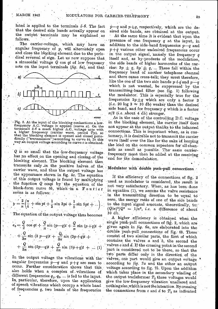
lated is applied to the terminals 5·6. The fact p-q and p-t.;q, respectively, which are the de-that the desired side bands actually appear on sired side bands, are obtained at the output.the output' terminals may be explained' as . At the same time it is evident that upon thefollows. . ? ". .' presence ·of .one frequency q at the input, in
The carrier-voltage, which mày have an additiön to the side-band frequencies 1J-q andangular frequency of p, will alternately open p +(1 various other undesired frequencies occurand close the blocking element due to the perio- . in the output signal, namely, the frequency qdical reversal of sign. Let us now suppose that. itself and, as .by-products of the modulation,a sinusoidal voltage Q cos qt of Iow frequency the side bands of higher harmonics of the car-acts ort theInput terminals (fig. 5a),"and th~t . rier: 3p ± q, 5p' ± q, ... These fal.lwibhin the
" .frequency band 'of another telephone channel~) ,~' .. ' ' ...~ .. ;_f... and there cause cross-talk; they must therefore,
~. ..', .. ,. like the one of the two side bands p+q: and p_qwhich is not wanted, be suppressed by the
' . ~ ..'. " transmitting-band filter (see fig. 1) followingb) I O+fUU0 0 0 nno ._t_ the modulator: This is especially true for the
, O' , . , frequencies 3p±q which are only. a factor 3'(i.e. 20 log 3 ~ 10 dbjweaker thanthe desiredside band, and for frequency q which is a factor'nf2 (i.e. .about 4 db) stronger:
As in the case of the controlling D.e. voltagein the blocking element, the èàrrier itself 'doesnot appear àt the output thanks 'to the balancedconneetdons. This IS important' when, as is cus-.tomary, it is desirable not to transmit the carrierwave itself over the Iinefor the sake of keeping,the load on the common repeaters for all chan-nels as small as possible. The' sáme carrier-frequency must then be added at the receiving.end for ,tlie demodulation. .
Q IS SO smaIi that the -Iow-frequency voltage,has no effect on the opening and closing. of theblocking element. The blocking element thentransmits only ~in the positive halves of the, • l\iodulator' with' double push-pull connectionscarrier wave, and thus the output voltage has . . . , .' _ .the appearance shown in fig. 50. The equation . If the efficiency ai the cormectdona of fig. 2
· of, this output, voltage is found by .multiplyi:r;:tg',used as modulator is considered', the result is, the function Q cosqt by ~t~e. equation o!_the not very satisfactory. ~hen, as has been. donebl?ck-~orm curve 5b, which 'Ill, a F 0 u r Ier .in equation (1), we assume the valve resistance'senes IS as follows: . . in the transmitting direction to be 'equal tó .:
zero, the energy ratio of one of the side bands 'to the input' signal amounts, üheoretically, to:'(Q/n)2fQ2 -- 1fn2, i.e. a difference of about10 db.A higher .efficiency is obtained when the
singlè push-pull connections of fig. 2,.which aregiven again in fig. 6a, are elaborated into thedouble push-pull .connections of fig.' 6b. Theseconsist of two sh~ilar parts; the first of whichcontains the valves a and Ob, the second the
: valves c and it. If-the crossing point in the secondpart is considered not to be there, so that thetwo' parts differ only in the direction of thevalves; one part would give an oubput voltage 'according to fig. 'la and the other an outputvoltage according to fig. 7b. Upon the additionwhich takes place' in the secondary winding ofthe output brarisfermer T2 these voltages wouldgive the low-frequency vibration 'unaltered andnothingelse, whichis not theintention. Byerossingthe connections from 0 and it to T2 as indicated
"
'". 40920.,
·. Fig. 5. At the input of the blocking connections a low..frequency A.C. .voltage is applied (curve a). On theterminals 5-6 a much higher A.C., voltage acts witha higher frequency (carrier waye, period Pp), sothat the blocking element is opened and closed perio-dically ("transmission") according to curve b). In thisway.an output, voltage according to curve c is obtained.. . .' .
.... .' '2 (n .' ' 1. 3" 1: . ')'!J - - - + SIllpt +- sm. pt +-:-sm 5pt + ... "· n 4 " , . 3· 5.· .
· The equation or'the.output·~oltage 'thus becomes1-° ., -' ",'
~o= 5? cos qt + g sin (p"':_q)t'+ 5? sin (.p+q)t +,,2 :n·, n
+..2. sin (3 p~q)t + Q? sin (3p+q)t +3n '_'... ,3n .
+'..2.'·Sjn(5p-q)t + ..2. sin (5p+q)t + ...('1)5n· ' ,,5n' . .
In the output voltage the vibrations with' the'. angulàr frequencies p~q and p+q are seen to .occur. Further consideration shows that this,
- also holds when a complex of. vibrations ofdifferent Irequencies qF q2' '" is fed to the input.In, particular, therefore, upon the applicationof speech vibrations which occupy a whole bandof frequencies (jo two bands of the frequencies
85

86 .' PUILIPS TECHNICAL RE:vmW' Vol. 7, No. 3
a
b
5 ' J1t
a). Fig. 6. a)
b)c)
6 5 pt 6
b)Modulation with single push-pull connections (identical to theblocking connections of fig. 2). .Modulator with double push-pull connections.Ring modulator (so called because the four valves are actuallyconnected in a ring one behirid the other). .'
in fig. 6b, however, the sign of the outputvoltage of fig. 7b is reversed, and upo.n a:dditionthe voltage represented in fig. 'te results. Thisvoltage is the product of the low frequency
Fig. 7. a) Output voltage Cab of the' upper part ofthe double push-pull connections of fig. 6b(Tp period of the carrier wave, Tq periodof the input voltage).
b) Output voltage ecd of the lower part with-:'out the crossing. . .
c) Output voltage eo -= eab~e~à of the whole.
component has disappeared from the outputsignal, while the energy ratio of one of the sidebands to the input signal is improved to ('/.QJn)2JQ2 = 4/]1;2,i.e. a difference of only 4·db. Oom-pared' with the. single connections, therefore,the efficiency is a factor 4 higher, since theeffeçtive signal has become 6 db stronger wibh
. the same input. voltage 3). . '" The connections of fig. 6b can still be simpli-fied to those of fig. 6c~.the so-called rin g-m 0 d u Ia tor, which is often used. This mod-:ulabor . is formed by superposing the two partsof 6b. It is easy to seé that no change occursin the functioning of the whole, since the super-posed points of the two parts always have thesame pobenbial.
Fig. 8. Variation of the transmission of the doublepush-pull connections as a function of. the time. ,Tp: period of the carrier wave. ' , . .
vibration Q cos' qt 'and tbe block-shaped curveof fig. 8. If .we again write the F 0 u r i e r-. More detailed consideration of the aetion of theseries for the 'latter, which is modulator .
4 ( . 1. 3 1"5 ' )Y =_ sm pt+ - sm pt + - sm pt + ...,'n ,3 5
and multiply this by Q cos qt, after working outthe equation for the output voltage we obtain,
~ ~o.=.2nQ{(sin (p-q)t+sin (p+q)t+ ~Si~(3P~q)t+
. +!. sin (3(p+q)t + !.sin (5p-q)t+ .~.'}. (2)3 .: 5 '.
The action of the double modulator connec-tions, according to this formula; is in the mainsimilar to that o'f the single eonneetdons of fig.6a, except that the undesired low-frequericy
In the foregoing it has all along been assumedthat the passage of the valves from the blockingstate to the transmitting spate and vice' versawas controlled exclusively by the carrier wave.Actually' it is not the carrier-voltage alonewhich is responsible for this, but the Gumof bhe,carrier and low-frequency voltages acting' oneach valve. Although the amplitude of .the car-rier voltage is much larger than that' of the low-frequency voltage, the latter, depending upon'its momentary value; will also contribute itsbib: by' causing the valve 'to function slightly. .
3) In practice in both cases the loss is further in-creased by about 2 db, which , may be ascribedto the losses in the valves and in the transformers.
MARCH 1942 MODULATOHS FOR CARRIER-TELEPHONY 87
sooner or later. The output voltage will thereforenot have exactly the' form shown' in fig: 5e(or 7e), but the zero points in the curve willsometimes be shifted slightly. to the left or tothe fight. "
Although it is clear that this effect will causethe occurrence of new undesired componentsinthe output signal, thiacannot Immediatelybe explained with the given method of represen-tation. If it is desired to take this effect intoaccount, it is no longer sufficient, simply toccnsider the modulator as a high-frequencyswitch, but the. behaviour of :the voltage oneach valve and the current caused thereby mustbe considered in more detail.
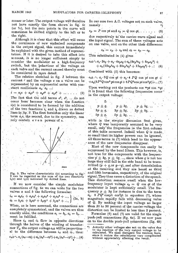
The relation sketched in fig. 3 between thecurrent l' and the voltage e on a valve can oerepresented by an exponential series with con-
. stant coefficients ~,' a2 ... : . .
. - a'e + 'a' 2 + 4 + 6 '+ (3).~ --. I 2e a4e, a4e ... . . .,The fact that th~ odd terms e3, eS, ... do notoccur 'here' becomes clear when the function·i(e) is ~considered to be formed by the additionof the two functions' il' and i2 drawn as dotted
, lines in' tig..9. The first furnishes only the linearterm ale, the second, due to its symmetry, can
, only èo~tain eve n powers of e.
, I e
'10924
Fig. 9. The 'valve characteristic i(e) according to fig.':2 can be regarded as the sum of the two functionsi1(e) and i2(e) indicated by dotted lines.
If we now consider the simple modulatorconnections of fig. 6a we can write for the twovalves a and b the following formulae: .
. ia = al.ea -+ a2ea?.+ a4ea4 + ~ea6 + ..., } b' . (3a, )ib = bleb + b2eb2+ b4e!>4+ bleb6 + ...,When, as is here assumed, the connections arecompletely symmetrical, and the valves are thusexactly alike, the conditions al = bI' ~. = b2, ...
must be fulfilled. ' ,. 'Since ia and ib flow in opposite dircctions
through the halves of the winding of transfor-mer T2, the output voltage eab will be proportion- , 4)al to the difference between ia and ib, thus:
, .eabrv al (ea-eb)+a2 (ea2-eb2)+a4 (èa4-€b4) +...(4)- , .
In our case two A.C. voltages act on each valve,namely 4)
ep = P cos pt and eg_. Q cos qt, . . . . .. (5).. - . ~
due respectively to-the'carrier-wave signal ar{d',_.the input signal. The sum of these voltages actson one valve, and on the other their difference:
. ea = ep + eq and eb = ep - eq., ~
This substituted in. (4) gives
eab."-val• 2eg_+ a2· 4epeg_+a4 (8ep3eq + 8epeq3) +_+a6(12ep5eg_ + 30ep3eg3 +12epel) + ..: (6)
Combined 'with (5) this becomes:
·eab.rva1·2Qcosqt +a2,4PQ cosptcosqt ++a4(8P3Qcos3 ptcos qt+ 8PQ3C?S ptcos3qt)+ ... (7)
Upon working out the products cos mpt cos. nqt .it is [ound that the following frequencies occur'in the output voltage:
-r :
q,p ± s.
. 3p ± q,._ 5p ± q,
p ± 3q,3p ± 3q,
.Sp ± 3q,
.» ± 5q, ...3p ± 5q,
, , ,
.while in the, simpler disoussion firat given,where Q was temporarily assumed to be verysmall, onlyühe frequencies in the first. columnof this table occurred. Indeed when Q is made :so small that its higher powers can be ignored,'all those terms in (7) which lead to the appear-
_. ance of the new frequencies disappear.Most of the new components can easily be,
suppressed by the band filters. 'I'his however, is,not true for the components with the frequen-cies 'p' ± 3q, P ± 5q, ... , since when q is not too, large they still fall in the side band tó be trans-mitted (p + q,or p"_:_q), and after demodulation.at the receiving end th_ey are heand as thirdand fifth harmonics, respectively, of the originalsignal. They thus cause a distortion of the speech.This distortion ,remains small when the low-frequency input voltage -eg_= Q cos qt of the
. modulator is kept sufficiently small. The fre-'quency p ± 3q for instance is due' to the terma4; 8 PQ3 cpspt cos3qt in equation (7), whosemagnitude rapidly falls with decreasing yalueof Q. By making' the input voltage no largerthan 20 to 30 percent of the carrier-voltage thedistortion can be Iimited to less than 2 percent. ,
Formulae (6) and (7) are valid for the singlepush-pull connections (fig. 6af If we now passon to the double push-pull coimections (fig. 6b)
Actually other voltages also act on the valve' dueto the reaction of the very output voltage to becalculated. We shall disregard thé reaction here,since it makes the calculations very complicatedwithout appreciably affecting the result. '
..

88,
PHILIPS TEOHNICAL REVIEW Vol. 7, No. 3,'
or thering modulator .(fig. 6'c) the output vol= , The relation between the current i and thetage can be found as before by adding the output voltage 'e given 'by such an arbitrarily curved.voltages eab and' eeä of the two parts with the characteristic can be represented by a series
, ,correct sign. Equation (6) holds foor eab, and quite analogous to equation (3), in which, how-for eeä an equation which, since the valves are' ever, all the 0 Cl: d powers of e must also occur:. reversed compared with a and b, can be obtainedby substitutip.g for ep in equation (6) - ep .andfor eq, -;-->- eq. When this is done, except for thefirst term, ecd is found to be identical ~o eaj,since in all the terms in epmeqn, the sum m +nis even; only the first term 2 ~eq has the oppositesign. Thus upon addition this term disappearswhile all the other ,terms are simply doubled.This agrees completely with the result of thesimplified discussion first given: by the doublingof the push-pull connections the low-frequencycomponent is suppressed and the efficiency ofthe modulator is increased by a, factor 4.
Fig. 11.-Tràn~missi~n region of the same characteristicas in fig, 10, but drawn on a smaller scale, so that thebehaviour at the voltáges actually used (order ofmagnitude 1 V) may be seen. The deviation from
._the 'idealized characteristic according :(;0 fig. 3 is1~-+~+-+---4___:'+--I--,-j--+-+_;_·flL.:.._j+--I--1 oonsiderable.
Valve characteristics which are not straight .. The double, push-pull connections however,have, etill another important advantage, whichàppears when.Insbead of the simple valve cha-racteristic (fig.' 3) assumed, the actual charac-teristics, of the valves In practical use are 'usedas a, basis ,of ,the calculabion.: In general these'characteristics deviate - oonsiderably from thestraight type sketched in fig. 3. In f~g· .1.0 for
,. !
t«A,6 '
5,
4
3
2
I I
.J02· 114V
, -I
"
-t8V -16" -t4 '~t2 -eo -(J8 '-G 6 -(J4 -02__.:.---2
40926
Fig. ID. Oharaèteristic of a selenium valve as used formodulators. .,.'. , .., . , '
instance the characteristic is given in the block-ing and transmitting directións of, a seleniumvalve 5) as used by Philips in modulators forcarrier-telephony, while in fig. 11 the tràns-'mission characteristic is drawn for a stilllargerrange of. currents 'and volta~es. ' . ,~. ,
6) -See W. Oh. van Geel, Blocking.layerrectifiers,Philips Techn. Rev. 4, 100, 1939.
e , (8)
15
,.
- - './ -
j' ,
'I / -
.
.1/ -
./' ,
- ;/,
mA20
10
5
,0o 0,5 1 1,5V4{)925
, '-
With this the calculationoî tl}e output voltagecan bè carried out in exactly.the same way as. above, and .one then finds for the, sin g I epush-pull connections instead ~f equation (6):
eab r-: ~ : 2eq '+ 'ai' 4 epeq + as (6 ep2eq +'2eq3)+ a4 (8 ep3eq + 8 epeq3) +..... . . .. (9)
The difference between this and equation' (6)ISthat now terms in epmeqn also occur in whichm+nis odd.Because of this, as is found uponsubstitution of (5)and further working out, in th eoutput signal there occur not only the side bands9f tho 0 d d harmonics of the carrier-wave, i.e.3p ± q" 5p ± q, etc.; but also the side bands ofthe even harmonics, i.e. 2p ± q, 4p ± q, etc.
In toble I (fifth column) this result. is placedbeside the frequency spectra found in the fore-6) The even harmonics of the input frequency q are "
always missing, even in the. side bands of bhecarrier wave and of the harmonics of the carrierwave.' This is due to the balance of the connectionsof fig. 6a, just as .in push-pull amplifiers, where the'ev(:)~ harmonics are also !ound to disappear. ','

MARCH 1942 MODULATORS FOR CARRIER-TELEPHONY 89
going, for the sake of comparison. Especiallythe components 2p ::t: q (and 2p ± 3q, 2p ± 5q,...) are a very undesirable "gain", since in orderto suppress them new and more rigorous require-ments are made of the transmitting-band filters ..
Tàble I
"Straight," characteristic Curved
Icharacteristic
Q~P QR:3P Q R:3 P
Single Double Single Double Single Doublepush- push- , push- push- push- push-pull pull pull pull pull pullq q q
3q5q...
p±q p ± q p ± q p ± q p ±q p ± qp ± 3q p ± 3q p ± 3q p ± 3q... ... ... ...
I I2p ± q2p ± 3q
...3p ± q 3p ± q 3p ± q 3p ± q 3p ± q 3p ± q
3p ± 3q 3p ± 3q 3p ± 3q 3p ± 3q... ... .,. ...
I"" ±, .4P.~ 3q
5p ± q 5p ± q 5p ± q 5p ± q_ 5p ± q 5p ± q5p ± 3q 5p ± 3q 5p ± 3q 5p ± 3q... ... ... ...
If we now again consider the double push-pullconnections and calculate the output voltage bywriting out eab and ecä and adding them, itwill be seen that upon substituting -ep for epand ---eq for eq in equation (9), it is just thenew terms with odd values of m + n whichchange their signs and thus disappear uponaddition. By the employment of the doublepush-pull connections, therefore, the disadvan-tage of the curved instead of straight valvecharacteristic is eliminated, as far as the numberof components in the output signal is concerned.This may clearly be seen from the table. Thisadvantage, together with that of the higherefficiency, leads to the common use of the doublepush-pull connections, in the form of the ringmodulator or not as the case may be.
Practical construction of the modulators
In the practical construction of the modula-tors the most important point is the choice ofthe valves. From the detailed considerationsof the action of the modulator which were basedupon equations (3) and (8) for the valve charac-teristics, it has been made clear that it is actuallynot the "valve" action of the circuit elements
in question, which action was emphasized inthe initial general discussion, which is essential,but in general the no n-l i ne a rit y of therelation between current and voltage. It isespeoially the square term a2e2 in the exponen-tial series which describes this relation (equation3 or 8) which causes the apparence of the desiredside bands p ± q. Every non-linear elementwhich possessesa characteristic with this term istherefore in principle suitable for the modulator.
In the early days of the development ofcarrier-wave telephony (around 1920) electronicvalves (triodes for example), such as those usedin radio technology, were used as non-linearelements. During the last ten years, however,
' in the modulators as well as in other parts of thecarrier-system where non-linear elements areneeded, the electronic valves have been replacedby blo c kin g-l aye r cells (blocking-layerrectifier valves), since the latter offer importantpractical advantages:'1) They possess no eleotrodes which require se-
parate supply like the cathode and anodeof the electronic valve. The connections andassembly therefore become simpler, thesupply apparatus of the whole installationbecomes smaller and the installation andrunning costs thus become lower.
2) The blocking-layer cells occupy very littlespace. This is demonstrated clearly in the
Fig. 12. On the right a single selenium cell as made byPhilips for general purposes of telephony. On the lefta "unit" of four cells for a modulator, in the middlethe same unit with the cover removed. The een-timer scale shows the small dimensions of the celland the unit.
photograph of fig.12, where a selenium cell(selenium rectifier valve) developed by Philipsfor the purposes oftelephonyis shown togeth-er with a unit of four such cells intendedfor a modulator with double push-pull con-nections 7). In fig. 13 it may be seen howthe unit is mounted in a complete modulator.
7) The small dimensions were made possible by thefact that these cells only need to carry verysmall currents, in contrast to selenium cells whichare used for instance in supply or charging ree-t.if'iers., See in this connection D. M. D u ink e r,Philips techno Rev. 5, 199, 1940.

90 PHILIPS TECHNICAL REVIEW Vol. 7, No. 3
3) The life of the blocking-layer cells with thelight loading here involved is very long, sothat the cells need not be placed at easilyaccessible spots, and greater freedom is thusobtained in the construction of the apparatus.
Fig. 13. Modulator of a carrier-telephone installationdeveloped by Philips, The largest part of the chassisis occupied by two transformers. To the left belowis the unit with the valves, above it a small potentio-meter for balancing (see below).
In the foregoing complete symmetry of themodulator connections has been assumed:the two or four blocking-layer cells in themodulator had exactly the same characteristic,the halves of the windings of the transformerswere exactly the same, etc. Actually this willnever be precisely the case. In particular thecharacteristics of the blocking-layer valves, anexample of which is given in fig. 11, alwaysexhibit some difference; upon comparison ofrandom examples the characteristics may evenbe quite different. The result of the dissymme-tries hereby introduced is that in the calculationof the output signal given above equation (4)is already na langer valid, sinceal ~ bIl a2 ;i:. h2,etc., so that for the single (equation 6) as wellas for the double push-pull connections termsin ep, e2p, e3p, e2q, epeq2, etc. still appear in theoutput voltage. Because of this, more or lessintense components with the frequencies p (thecarrier), 2p, 3p, 2q, P ± 2q, etc. also occur asproducts of the modulation. The oscillogram offig. 14 shows the effect of these on the form ofthe output signal. _Among these extra modulation products the
carrier wave p could only with much difficultybe suppressed by the filters, while this is evenfundamentally impossible for the frequencies p± 2q, P ± 4q, etc. (as in the case of the com-ponents p _± 3q, P ± 5q, .. , mentioned above),since they may fall within the desired side band
itself. Now in order to keep these terms, andespecially the so-called carrier-leak, small, thedissymmetries of the modulator must be limitedas far as possible. For that purpose in the firstplace great care is devoted during manufacturenot only to obtaining the greatest possiblesymmetry in the construction of the transfor-mers, but also to selecting two or four valvesas nearly as possible alike. Account must alsobe taken of the requirement that sufficientsymmetry is maintained during use fat a reason-able time. The dependence of the valve charac-teristic on the temperature and the smallchanges in the valve properties with time'(ageing) must therefore be as nearly as possibleidentical for the four valves to be combined.
In the second place a small potentiometermay be connected between the halves of thewindings of the primary of the transformer T2,
as was already indicated in the diagram of fig.6c. By this means slight residual dissyrn-metries of t.he valves and transformers can bebalanced, at least as long as the dissymmetrieslie in the real part of the impedances. Sincethe blocking-layer valves possess a certain capa-city and the transformers a certain leakage self-induction, which mayalso cause some dissym-metry, a complex resistance must actually beused for the balancing, for example a potentio-meter in parallel with a differential condenser.In most cases, however, the carrier-leak canbe adjusted to a sufficiently small value evenwithout the last-mentioned element.
Fig. 14. Oscillogram of the output voltage of a modu-lator in double push-pull connection. The carrier-frequency here amounted to 6 000 c/sec, the low-fre-quency input voltage had a. frequency of 600 ejse»,The deviations of the curve from the ideal form areto be ascribed mainly to dissymmetries in the modu-lator connection_s.
In conclusion a few words about the d e m o-d u Ia tor, which serves to restore the fre-quency bands arrriving at the receiving end totheir original frequency region. In principle itis similar to the modulator and the same appa-ratus can be used. If, for example, we apply tothe modulator a signal with the frequency p + qand a carrier wave with the frequency p, amongother voltages those with the sum and difference

MARCH 1942 MODULATORS FOR CARRIER-TELEPHONY 91
ON THE POROSITY OF W·ELDS
frequency 2p + q and q will occur at the output.Furthermore a number of undesired modulationpr.oducts also occur again, which we can imme-diately derive from table I by replacing q by
p+q. Of all the output components onlythose with the frequency q are desired, theothers being suppressed as far as possible in thelow-pass filters following the demodulator.
by J. TER BERG 1).
In electric arc welding the weld is sometimes found to be porous. This porositycan be caused by the presence of sulphur. Certain welding rods are very sen-sitive to sulphur, while others are insensitive to it. In this article some experi-ments are described which illustrate the importance of the sulphur contentof the material being welded on the resulting weld. In particular these experi-ments show that the non-uniformity of the distribution of sulphur in the workpiece can affect the results obtained. It is also shown that it is advisableto use rods which are insensitive to sulphur.
One of the most important problems in weld-ing technique is that of the measures whichshould be taken to obtain a weld with goodmechanical properties. Especially in electricare welding with coated electrodes it occasion-ally occurs that the weld is porous, whichmeans a considerable decrease in the mechanicalstrength. It is clear that the occurrence of sucha phenomenon or even the possibility of itsoccurrence is a strong impediment to the appli-cation of arc welding.In the course of years many attempts have
been made to discover the causes of the porosity.A successful result was only obtained whenexperiments were carried out in this laboratorywith the object of investigating the rehtionbetween porosity and the presence of sulphur.
"""',Fig. 1. Fillet weld made with a sulphur-sensitiveelectrode on a material containing considerablesulphur. The bead is porous and contains pocks andis, moreover, cracked.
1) Partially in collaboration with 1 r. J. Sac kt.
621.791.056
Fig. 2. Rolled and etched strip with sulphur segregation.This may clearly be seen on the pohshed surface.
For this purpose the element in question wasexpressely added to a large number of differentkinds of welding rods, The addition of sulphurcan be realized in a simple way by immersingthe coated electrode in a saturated solutionof sodium sulphate for ft certain time and thendrying it.These experiments led to the surprising result
that in the case of certain kinds of rods a verysmall amount of sulphur 2) was able to causethe porosity 3) under consideration, while withother types even a large percentage of sulphurhad no effect on the soundness of the weld.We shall call the first type sulph u r-s en sit iv eelectrodes and the second type su Ip h u r-2) The elements following sulphur in the periodic
system, selenium and tellurium, exhibit this spe-cific effect of producing porosity to an even greaterdegree. Phosphorus, however, which, is often clas-sed with sulphur as far as its effect on metalsis concerned, does not have this property.
3) By porosity in this connection must also be under-stood the phenomenon where the surface of theweld is covered with small depressions, usuallycalled pock-marked.