ip net 5 presentation - building the ksbe network · 2013-03-20 · ip networking part 5...
TRANSCRIPT

IP NetworkingPart 5 ‐ Building the
KSBE NetworkKSBE Network“A webinar to help you prepare
for the CBNE™ Certification”
Wayne M. Pecena, CPBE, CBNE
Texas A&M Information TechnologyEducational Broadcast Services

IP Networking‐Part 5 ‐ Building the KSBE Network“A webinar to help you prepare for the CBNE™ Certification” p y p p f f
Advertised Presentation Scope:p
The IP Networking webinar series continues with part 5 focusing on “Building the KSBE Network", by applying the concepts addressed in the first 4 parts of the IP Networking Webinar series. The end result of this webinar will be an understanding of how to build an IP network infrastructure often found in a broadcast environment. The “KSBE Network” will address layered IP network design, application of an IP addressing plan, use of VLAN’s, routing protocols, securing the network, and access et o des g , app cat o o a add ess g p a , use o s, out g p otoco s, secu g t e et o , a d accessto the network through a secure VPN connection.The IP Networking Webinar series is focused on enhancing the Broadcast Engineers knowledge of the technology and practical concepts of IP Networking in the broadcast plant. In addition, the webinar series provides an excellent tutorial for those preparing for SBE networking certifications such as the CBNE.
My Goals & Deliverables for This Afternoon:
‐ Provide an Awareness of Network Design Principalsf‐ Provide an Understanding of Factors in Network Design
‐ Provide a Foundation for SBE CBNT & CBNE Certification Exams‐ Provide Reference Material & Resources to Obtain Further Knowledge
2

Agenda
• Introduction
• Network Design Concepts• Network Design Concepts
• Layered Network Design
• The Building BlocksS d d– Standards
– Network Topologies
– IP Address Plan (IPv4 focused)
– VLAN ImplementationVLAN Implementation
– When to Route – When to Switch?
• Securing the Network
• Access the NetworkAccess the Network
• “Assembling the KSBE Network”
• Best Practices Summary / Q & A
f• Reference Documents
3

5 Things Required To Build a Network5 Things Required To Build a Network
• Send Host
• Receive Host
• Message or Data to Send Between Hosts
• Media to Interconnect Hosts
• Protocol to Define How Data is Transferred
4

Network Design ConsiderationsNetwork Design Considerations
• PerformancePerformance
• Reliability / Redundancy
S l bili• Scalability
• Security
• Flexibility
• ManageabilityManageability
• Affordability
5

The Design ProcessThe Design Process
6

The Basic NetworkThe Basic Network
7

The LAN EnvironmentThe LAN Environment
8

Adding Redundant ISP’sAdding Redundant ISP s
9

More Redundancy!More Redundancy!
10
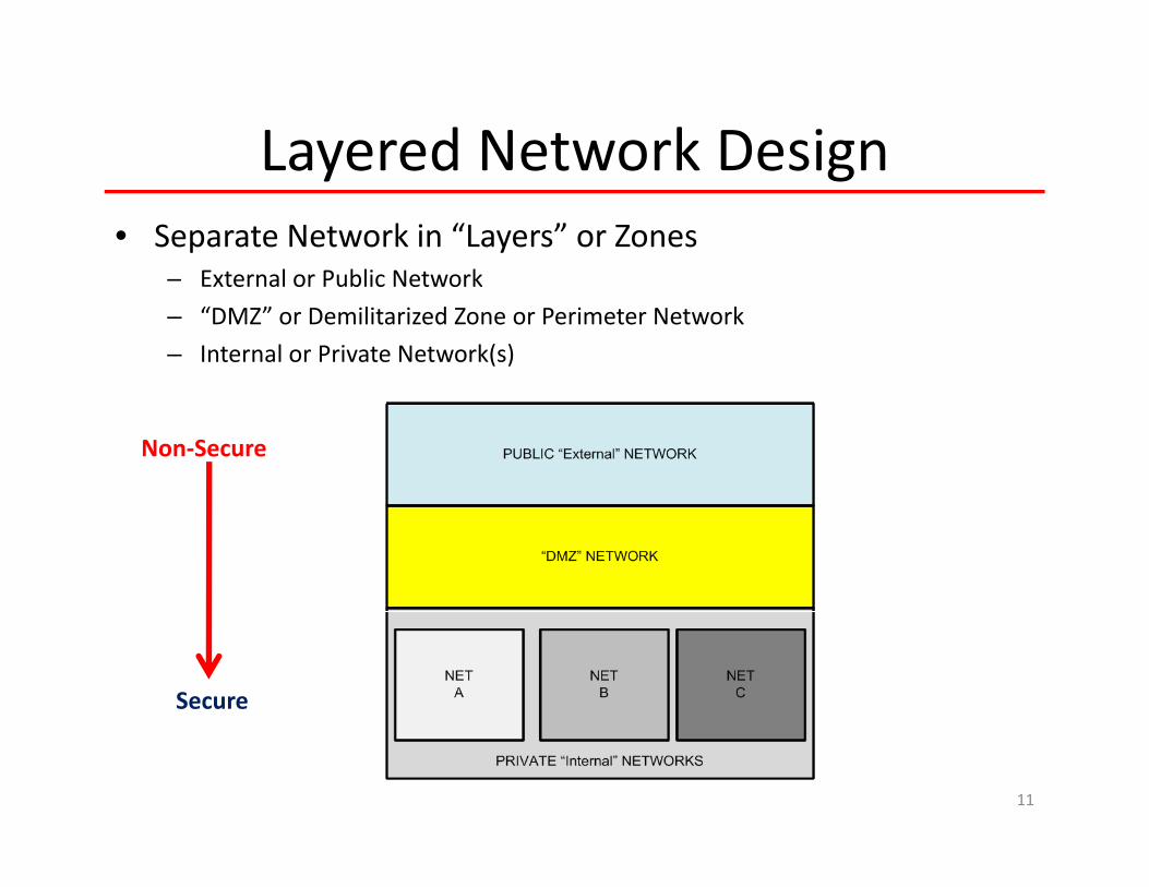
Layered Network DesignLayered Network Design• Separate Network in “Layers” or Zones
External or Public Network– External or Public Network
– “DMZ” or Demilitarized Zone or Perimeter Network
– Internal or Private Network(s)
Non‐Secure
Secure
11

StandardsStandards• OSI Model & IETF RFC’s
I l S d d• Internal Standards:– Device Naming Scheme
• Device Type
• Device Number
• Device Location
– IP Addressing Scheme– IP Addressing Scheme
• Public
• Private
– VLAN Naming Scheme
– Wiring Schemes
12

OSI ‐ DoD ‐ TCP/IP ModelsIP Focused ‐ DOD Model Stack or TCP/IP Model
13

Reference Hardware & ServicesReference Hardware & Services
• Physical Medium(s)Physical Medium(s)
• Switches
• Routers
• Firewalls
• VLAN(s)
• VPN(s)VPN(s)
14

Managed vs Un‐Managed Ethernet SwitchesManaged vs Un Managed Ethernet Switches
• Managed Switch– User Configurable
• Un‐Managed Switch– Fixed Configuration
– Provides Ability to Control & Monitor Host Communications
– Port Configuration , Security, & M i i
– “Plug & Play”
– Provides Basic Host Communications
Monitoring
– VLAN Implementation
– Redundancy Supported (STP)
( )
Communications
– Cheaper
– QoS (Prioritization) Implementation
– Port Mirroring
15

AddressingPh i l & Vi l Add iPhysical & Virtual Addressing
• Each Host on an Ethernet Based IP Network Has:Each Host on an Ethernet Based IP Network Has:
• An Unique MAC Address– Layer 2 Physical Address (local network segment)
• An Unique IP Address– Layer 3 Logical Address (global routed)
16

IP Address PlanIP Address Plan
• Required Space vs Available SpaceRequired Space vs Available Space
• Private Addresses
“ bli ” dd• “Public” Addresses
• Static Assignment
• Dynamic Assignment
17

The IP Address Subnet MaskEach IP Address Must Have a Subnet Mask
18

IP Address SubnettingIP Address Subnetting• What is a Subnet?
– Logical Subdivision of a Larger Networkg g
– Creates New Networks From A Larger Network
– Bits Are “Stolen” From the Host Portion
• Each Newer Network Created Has Less Hosts
• 2n‐2 New Networks Created where n=number of host bits stolen
• Why Do We Subnet?• Why Do We Subnet?– Efficient Use of IP Address Space (“Right Size” the Network)
– Increase Performance (smaller Broadcast domain)
– Enhance Routing Efficiency (reduce Routing Table size)
– Network Management Policy and Segmentation(function, ownership, geo location)
– Job Security for Network Engineers!
19

Subnet ExampleSubnet Example
Network Existing Design RequiredNetwork Existing Hosts
DesignHosts
Required Subnet Size
A – Sales 35 40 64
B – Eng 17 20 32B Eng 17 20 32
C ‐ Prod 27 30 32
20

Network Address Translation – NATRFC 1631
• Allows Mapping Internal (private) Address Space to External (public) Address SpaceAddress Space
– Allows Internal IP Addresses to be Hid (Security)
– Can Conserve IP Public Address Space
21

Building the IP Network Infrastructure
• Layered Network DesignLayered Network Design
• SwitchingVLAN( )– VLAN(s)
• Routing
• Access Control– Tunnels
– Firewalls
22

Switching vs RoutingWhen to Switch? ‐‐When to Route?
23

Switching FundamentalsSwitching Fundamentals
• Legacy Ethernet Used Hubs– An “Ethernet DA” of sorts – All Bits Go to All Ports
– High Collision Level Due to Shared Media(40‐50% of Bandwidth Consumed by Collision Recovery)
– High Collision Level Yields High Latency
• Switches Allow Segmentation of Network– Allows Dedicated Bandwidth and Point‐Point Communications
– Increased Throughput Due to Zero or Minimal Collisions
– Allows Full‐Duplex Operation
– Increased Security CapabilityIncreased Security Capability
• Switches Selectively Forward Individual “Frames” from a Receiving Port to a Destination Portto a Destination Port
24

VLANS Are Your Friend!VLANS Are Your Friend!
• Virtual Local Area Network – VLAN– Logical Network of a Physical Network
• Allows Separation of Networks Across a Common Physical Media– Creates Subset of Larger Network
Control Broadcast Domains Each VLAN is a Broadcast Domain– Control Broadcast Domains – Each VLAN is a Broadcast Domain– Architecture Flexibility– Security
• Static Port Based VLAN(s)– Most Popular– Manual Configuration
• Dynamic Port BasedMAC B d VLAN( )– MAC‐Based VLAN(s)
• Assignment Based Upon MAC Address
– Protocol‐Based VLAN(s)• Assignment Based Upon Protocol
25
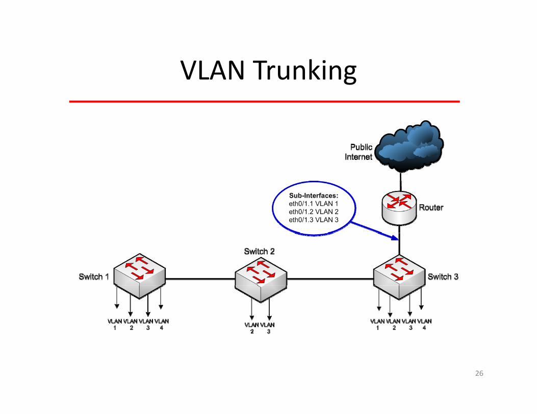
VLAN TrunkingVLAN Trunking
26

VLAN ExamplePhysical Representation of Previous Diagram
Switch Port Type Configuration:
Access Link – Member of One VLAN Only Connects to a HostyTrunk Link – Carries Traffic From Multiple VLANS Between Switches
27

Interface ConfigurationInterface Configuration
28

Broadcast DomainsBroadcast Domains
29

Connectivity Between Broadcast DomainsConnectivity Between Broadcast Domains
Network #1 Network #3
GE0 GE2
Network #1 Network #3
Network #2
GE1 Unique IPAddressRange
Unique IPAddressRange
Unique IPAddress
Network #2RangeRange
FE0
30
RedVLAN
GreenVLAN
BlueVLAN

RoutingRouting
• Routing is Simply the Moving of Data Between Networksg p y g
• OSI Model Layer 3 Process
• Routing Involves Two Processes:
– Determining the Best Path The Hard Part
– Actually Sending of the Data The Easy Part
• Static Routing
– Stub Routing (used when only one path exists)
• Dynamic Routing• Dynamic Routing
– Path is Automatically Determined
31

Routing Types:Routing Types:
• Static RoutingStatic Routing– Appropriate for Small Networks
– Appropriate for Stable Networks
– Use in “Stub” Networks
– Minimal Hardware / Easy Administration
• Dynamic Routing– Appropriate for Changing Topology Environments
– Desirable When Multiple Paths Exist
– More Scalable
– Less Configuration Error ProneLess Configuration Error Prone
32

Routing Protocol ChoicesRouting Protocol Choices
Interior Distance Vector
Interior Link State Exterior Path Vector
Cl f l I IG GClassful RIP IGRP EGP
Classless RIP v2 EIGRP OSPF v2 IS‐IS BGP v4
IPv6 RIPng EIGRP v6 OSPF v3 IS‐IS v6 BGP v4
33

Practical Routing Protocol Choices“Common” IGP Protocols – VLSM Support
RIP v2 EIGRP (Cisco) OSPF v2
Type: Distance Vector Hybird Link‐State
Metric: Hop Count Bandwidth/Delay Cost
Administrative 120 90 110Administrative Distance:
120 90 110
Hop Count Limit: 15 224 None
Convergence: Slow Fast FastConvergence: Slow Fast Fast
Updates: Full Table Every 30 Seconds
Send Only Changes When Change Occurs
Send Only When Change Occurs, But RefreshedChange Occurs But Refreshed Every 30m
RFC Reference: RFC 1388 N/A RFC 2328
34

Routing Protocols:gWhich One is Best?
“It Depends”ISP BGP RIP
It Depends
OSPF
EIGRP
35

Which RoutingProtocol?
Static DynamicStaticRouting
DynamicRouting
EGP IGP
BGP
DistanceVector
Protocol:
Link State Protocol:
RIP IGRP OSPF IS-ISRIP IGRP OSPF IS-IS
Hybrid
Standards Based
yProtocol:
EIGRP
Proprietary
36

Unicast or Multicast ?Unicast or Multicast ?
Diagram Courtesy of:

When to Route – When to Switch?When to Route When to Switch?
Broadcast Domain
When to ROUTE?“Breaks the Broadcast Domain”
CollisionDomain
CollisionDomain
RouterCollisionDomain
CollisionDomain
When to SWITCH?“Breaks the Collision Domain”
Broadcast Domain
38

Routing & Switching SummaryRouting & Switching SummaryBroadcast Domain
CollisionDomainRoute Between Networks
(Broadcast Domains)
Collision Collision
Switch to Break CollisionDomain Within a
Broadcast DomainRouter
CollisionDomain
CollisionDomain
Switch Switch CollisionDomain
Hub
Broadcast Domain
CollisionDomain
CollisionDomain
SiSiSiSiSiSiLayer 3Switch
Broadcast Domain
CollisionDomainCollision
Domain
39
Broadcast Domain
Broadcast Domain

What Is A “Layer 3” Switch?What Is A Layer 3 Switch?
• “Marketing Terminology” Applied to a One Box Solution:
– Layer 2 Switching or Forwarding
• Traditionally Performed in Hardware
– Layer 3 Routing or Forwarding
• Traditionally Performed in Software
• Layer 3 Switch Performs Both
• Can Eliminate Use of VLAN(s) – Each Port Can Be Assigned to a Subnet
• Not for All Environments• Not for All Environments– Typically Found in Workgroup Environment
– Limited to Ethernet
– Limited to OSPF and RIP Protocols
40

The Security ChallengeThe Security Challenge
PERFORMANCESECURITY USEABILITYSECURITY USEABILITY
41

Goals of Network SecurityGoals of Network Security
• ConfidentialityConfidentiality“Keeping Data Private”
• Integrity“Insuring Data Has Not Been Modified”
• Availability“ l bl h d d ”“Insuring Data is Available to the Intended User”
42

Network Security – The First StepNetwork Security The First Step
• Control Access to the NetworkControl Access to the Network– Open or Available LAN Switch Ports?
Can I get an IP Address?– Can I get an IP Address?
– If I get an IP Address, can I get Network Access?
• First Step:L k d ll LAN it h t– Lock down all LAN switch ports
– Require Users & Devices to Authenticate (802.1xX)
43

Network Security ConcernsNetwork Security Concerns
• Focused on Protecting the Network Infrastructure
• Common Threats:– DHCP Snooping
– ARP Spoofing (IP Spoofing)
d– Rogue Routers Advertisements
– Denial of Service Attacks
– Application Layer Attacks
• Implementation Considerations:• Implementation Considerations:– Know Your Enemy
– Cost
– Human Factors
– Understand Your Network
– Limit Scope of Access
– Don’t Overlook Physical Security
44

SecuritySecurity
• FirewallsFirewalls
• Intrusion Detection
C• Content
• Physical
• Regulatory
• CommunicationsCommunications
• Access
45

Switch Port Security “Port Lockdown”Switch Port Security Port Lockdown
• An Important Feature of Implementing SwitchAn Important Feature of Implementing Switch Infrastructure
• Port Security Aspects:y p– One MAC Address Per Port
• Dynamic
St ti• Static
– n MAC Addresses Per Port
– Unused Ports Disabled
– MAC Violation Action
– VLAN Specified Per Port
46

IT Infrastructure ThreatsIT Infrastructure Threats
• Viruses • Operating Systems• Worms• Trojan Horse
S & Ad
• File System / Media• Application
Web Services• Spyware & Adware• Botnets “Zombie
Computer”
– Web Services– Email Services– P2P
Wi l / M bil• Wireless / Mobile Environment
• Social Engineering• And the list goes on & on…..
47

Network Infrastructure ThreatsNetwork Infrastructure Threats
• Denial of Service “DoS”
• Spoofing
• Hijacking
• Authentication Bypass or “Back Door” Access
• Physical Access• Physical Access
• And the list goes on & on…..
48

Can You Balance Your Network fInfrastructure?
“DoS”VirusesWormsTrojan HorseSpyware Adware
DoSSpoofingHijacking“Back Door” AccessPhysical AccessS i l E i i USEABLEAdware
Botnets Social EngineeringPhishingAnd more …..
49
The Goal – “Create a Secure But Useable Network”

Network Security ToolsNetwork Security Tools• Firewall
– Used to Create a “Trusted” Network Segment by Permitting or DenyingUsed to Create a Trusted Network Segment by Permitting or Denying Network Packets
– Types of Firewalls:• Packet Filtering
– Stateless– Stateful
• Detection Tools– Intrusion Detection Systems (IDS)
• Signature Based• Anomaly Based
– Intrusion Prevention Systems (IPS)• Combine Firewall & IDS Functions
50

FirewallsFirewalls
• FirewallFirewall– Defines Traffic Types That Can Enter or Exit a Network
– Can Be Software Based
• Access Control List “ACL” Applied to Router or Switch Interface – Ingress or Egress Filtering:
– IP Address Filtering
– Port Number Filtering
MAC Add Filt i–MAC Address Filtering
– May Be Hardware Based “Appliance”
51

Firewall Types:Firewall Types:Packet Filtering - “Stateless” Packet Filtering - “Stateful”
52

Firewall Implementation“The 3‐Armed Firewall”
53

VPN Implementation“Virtual Private Network”Virtual Private Network
Demilitarized Zone“DMZ”
EmailServer
WebServer
RemoteUser
(VPN Client)
ApplicationServer
Internet(Outside)
InternalNetwork(s)
VPNConcentrator
ApplicationServer
VPNAccessAppliance
54RemoteOffice

Don Not Confuse VLAN’s and VPN’sE f VPN i T l Th h N k I fEssence of a VPN is a Tunnel Through a Network Infrastructure
Virtual Private Network VPN ProtocolsVirtual Private Network – VPN Protocols- IPsec with Encryption - L2TP inside of IPsec - SSL with Encryption
55

Packet Filtering & ShapingPacket Filtering & Shaping• Packet Filtering
A Fi ll i U d C “T d” N k S b P i i D i– A Firewall is Used to Create a “Trusted” Network Segment by Permitting or Denying Network Packets
– Can Be Implemented in Router with Access Control Lists (ACL)– Ingress Filtering– Egress Filtering– Types of Firewalls:
• Packet Filtering:– Stateless – Filters Solely on Packet Infoy– Statefull – Identifies as Packet Stream Component
• NextGen – Provide Application Awareness
• Packet ShapingPacket Shaping– A Traffic Shaper is Used to Control the Volume of Traffic on a Network Segment– Generally Achieved by Delaying Packets– Traffic is Classified – Rules Applied Based Upon Classification
56

Quality of Service – “QoS”IEEE 802.1P/Q
• Why QoS?• Why QoS?– All IP Packets Are Created Equal, But The Application Data Contained
Within an IP Packet May Not Be.
– Q0S Allows Network Traffic to Be Prioritized Based Upon the Application to Insure Packet Delivery:
• Streaming Media (Audio over IP – Video Over IP)
• IP Telephony (Voice over IP)
• Real‐Time Control (automation control)
• Mission Critical ApplicationsMission Critical Applications
57

Assembling the Pieces
58

Some Best Practices to Consider
• Recognize Physical Security
• Change Default Logins
• Keep Up With Equipment “Patches”
• Utilize Access Logging on Key• Change Default Logins
• Utilize Strong Passwords
• Disable Services Not Required
• Adopt a Layered Design Approach
• Utilize Access Logging on Key Network Devices
• Utilize Session Timeout Features
• Encrypt Any Critical Data• Adopt a Layered Design Approach
• Segregate Network(s)
• Separate Networks via VLANS
• Implement Switch Port Security
Encrypt Any Critical Data
• Restrict Remote Access Source
• Understand & Know Your Network Baseline• Implement Switch Port Security
• Utilize Packet Filtering in Routers & Firewalls
• Do Not Overlook Egress Traffic
• Actively Monitor and Look for Abnormalities
• Limit “Need‐to‐Know”Do Not Overlook Egress Traffic
• Deny All Traffic – Then Permit Only Required
• Disable External “ICMP” Access
59

Document What You Do!
60

61

CBNE Recommended Study:
62

My Favorite:My Favorite:
63

Web Reference Sources:
IETF RFC Documents:www.rfc-editor.org
Learn More About the OSI Model:http://www.9tut.com/osi-model-tutorial
Learn More About Switching:http://www technick net/public/code/cp dpage php?aiocp dp=guide networking switchinghttp://www.technick.net/public/code/cp_dpage.php?aiocp_dp=guide_networking_switching
Learn More About Routing:http://www.inetdaemon.com/tutorials/internet/ip/routing/index.shtml
Learn More About Layer 3 Switching:y ghttp://happyrouter.com/layer-3-switches-explained
Learn More About QoS:http://docwiki.cisco.com/wiki/Quality_of_Service_Networking
64

? Questions ?
Thank You for Attending!
? Questions ?
Wayne M. PecenaTexas A&M UniversityTexas A&M UniversityOffice of Information Technology
@t dw‐[email protected]@tamu.edu
979.845.5662
65