ip routing primer - mik
TRANSCRIPT

IP Routing PrimerPreface●
Topology and Router Configurations●
Routing Metrics and Distances●
Discontiguous Networks, Summarization, and Subnet 0●
Using IP Unnumbered and VLSM●
Default Routing●
IP Troubleshooting Scenarios●
Bridging IP Between Dissimilar Media●
Hexadecimal and Binary Numbering and IP Addressing●
Appendix A: RFCs●
Copyright 1989-1999 © Cisco Systems Inc.
IP Routing Primer
http://wwwin.cisco.com/cpress/cc/td/cpress/fund/primer/index.htm [02/02/2001 11.55.49]

March 1999
Welcome to Cisco PressWelcome to the employee only Cisco Press web site. The above "Welcome" page link presents aFAQ sheet for Cisco Press, including information about how you can buy Cisco Press books!.
New information on the Cisco Press Marketing Incentive Plan is also now available.
As source material becomes available from the publisher, the complete text of each Cisco Presspublication will be presented here for use by Cisco employees. Sample chapters are presented at thepublic site hosted by Cisco.
Design and ImplementationPublications focusing on network design and implementation strategies.
Internet Routing ArchitecturesISBN: 1-56205-652-2By Bassam HalabiExplores the ins and outs of interdomainrouting network designs.
Designing Campus NetworksISBN: 1-57870-030-2By Terri Quinn-Andry and Kitty HallerFocuses on designing scalable networkssupporting campus LAN traffic.
OSPF Network Design SolutionsISBN: 1-57870-046-9By Thomas M. Thomas IIPresents detailed, applied coverage of OpenShortest Path First protocol.
Internetworking SNA with Cisco RoutersISBN: 1-57870-083-3By George Sackett and Nancy SackettProvides comprehesive coverage of terms,architectures, protocols, and implementationsfor internetworking SNA. Content notavailable.
Residential BroadbandISBN: 1-57870-020-5By George AbePresents emerging high-bandwidth accessnetwork issues.
Cisco Router ConfigurationISBN: 1-57870-022-1By Allan Leinwand and Bruce PinskyPresents router deployment tips fromlong-time Cisco experts.
Top-Down Network DesignISBN: 1-57870-069-8By Priscilla OppenheimerLearn a network design methodology basedon standard techniques for structured systemsanalysis.
Cisco Press Internal Home Page
http://wwwin.cisco.com/cpress/home/home.htm (1 of 3) [02/02/2001 11.56.06]

Cisco Career Certification and TrainingPublications developed in cooperation with Cisco Worldwide Training that support Cisco's CareerCertification and customer training initiatives.
Introduction to Cisco RouterConfiguration (ICRC)ISBN: 1-57870-076-0Edited by Laura ChappellBased on the Cisco course, presents readerswith the concepts and commands required toconfigure Cisco routers. Content notavailable.
Cisco CCNA Preparation LibraryISBN: 1-57870-125-2By Cisco Systems, Inc.Bundle includes two publications:Introduction to Cisco Router Configurationand Internetworking TechnologiesHandbook, Second Edition (plusHigh-Performance Solutions for DesktopConnectivity in CD-ROM format). Contentnot available.
Advanced Cisco Router Configuration(ACRC)ISBN: 1-57870-074-4Edited by Laura ChappellAdvanced guide focuses on scalableoperation in large and/or growingmultiprotocol internetworks.
Cisco Certified Internetwork Expert (CCIE)Professional Development SeriesPublications supporting Cisco's CCIE program.
Cisco CCIE Fundamentals: NetworkDesign and Case StudiesISBN: 1-57870-066-3By Cisco StaffNetwork design fundamentals and caseexamples assembled to help prepare CCIEcandidates.
CCIE Professional Development: RoutingTCP/IPISBN: 1-57870-041-8By Jeff DoyleCovers basics through details of each IProuting protocol. Essential reading! Contentnot available.
Networking FundamentalsSupport publications providing technology and configuration basics.
Internetworking Technologies Handbook(2nd Edition)ISBN: 1-56205-102-8By Cisco Staff and Kevin DownesSurvey of technologies and protocols.
Internetworking TroubleshootingHandbookISBN: 1-56205-024-8By Cisco Staff and Kevin DownesSummarizes connectivity and performanceproblems, helps develop a strategy forisolating problems. Content not available.
IP Routing PrimerISBN: 1-57870-108-2By Robert WrightTechnical tips and hints focusing on howCisco routers implement IP functions.
IP Routing FundamentalsISBN: 1-57870-071-XBy Mark SportackProvides a detailed examination of routersand the common IP routing protocols.
Cisco Press Internal Home Page
http://wwwin.cisco.com/cpress/home/home.htm (2 of 3) [02/02/2001 11.56.06]
Cisco Documentation from Cisco PressA number of Cisco IOS cross-platform software publications have been ported to a retail format byCisco Press. Cisco Press is selling these documents via retail channels as a courtesy to simplifyaccess for Cisco customers. All these documents, whether sold as Cisco product documents or as theCisco Press publications, are available in electronic form via Cisco's free web-based,documentationsite.
To find publications offered by Cisco Press, please refer to the catalog of publications presented atthe Cisco Press page hosted by Macmillan:
Complete Cisco Press Publication Catalog●
The links below direct you to the documents presented within the official Cisco documentationenvironment (and out of the Cisco Press web area).
Cisco IOS Software Release 11.3 Documentation●
Cisco IOS Software Release 12.0 Documentation●
Copyright 1988-1999 © Cisco Systems, Inc.
Cisco Press Internal Home Page
http://wwwin.cisco.com/cpress/home/home.htm (3 of 3) [02/02/2001 11.56.06]

Internetworking FundamentalsIP Routing Fundamentals●
IP Routing Primer●
Internetworking Technologies Handbook (2nd Edition)●
Copyright 1989-2000 © Cisco Systems Inc.
Internetworking Fundamentals
http://wwwin.cisco.com/cpress/cc/td/cpress/fund/index.htm [02/02/2001 11.56.08]

IP Routing FundamentalsIntroduction●
An Introduction to Internetworking●
Understanding Internetwork Addresses●
Routers and LANs●
Routers and WANs●
Internet Protocols Versions●
Transmission Technologies●
The Mechanics of Routing Protocols●
RIP●
RIP V2●
IGRP●
Enhanced IGRP●
OSPF●
Building Internetworks●
Internetworking with Dissimilar Protocols●
The Future of Routing●
Copyright 1989-1999 © Cisco Systems Inc.
IP Routing Fundamentals
http://wwwin.cisco.com/cpress/cc/td/cpress/fund/iprf/index.htm [02/02/2001 11.56.11]

Internetworking TechnologiesHandbook (2nd Edition)
Internetworking Basics●
Introduction to LAN Protocols●
Introduction to WAN Technologies●
Multiservice Access Technologies●
Banyan VINES●
Directory-Enabled Networking●
Network Caching Technologies●
IBM Network Management●
RMON●
SNMP●
Copyright 1989-2000 © Cisco Systems Inc.
Internetworking Technologies Handbook (2nd Edition)
http://wwwin.cisco.com/cpress/cc/td/cpress/fund/ith2nd/index.htm [02/02/2001 11.56.12]

Internetworking Terms andAcronyms
Introduction●
Numerics●
A●
B●
C●
D●
E●
F●
G●
H●
I●
J●
K●
L●
M●
N●
O●
P●
Q●
R●
S●
T●
U●
V●
W●
X●
Internetworking Terms and Acronyms
http://wwwin.cisco.com/cpress/cc/td/doc/cisintwk/ita/index.htm (1 of 2) [02/02/2001 11.56.18]

Z●
ITA New Terms October 2000●
Copyright 1989-2000 © Cisco Systems Inc.
Internetworking Terms and Acronyms
http://wwwin.cisco.com/cpress/cc/td/doc/cisintwk/ita/index.htm (2 of 2) [02/02/2001 11.56.18]
Cisco Press SearchEnter your query here:
Search Help
Copyright 1989-1997 © Cisco Systems Inc.
Cisco Press Search
http://wwwin.cisco.com/cpress/home/search.htm [02/02/2001 11.56.24]

Cisco Press HelpUser Interface Overview●
Basic notes about the Cisco Press site user interface.
Searching Cisco Press●
Instructions regarding use of the multi-document search feature provided with this product.
Copyright 1988-1997 © Cisco Systems Inc.
Cisco Press Help
http://wwwin.cisco.com/cpress/cc/lib/help.htm [02/02/2001 11.56.26]

Table of Contents
Introduction
Objective of This BookAudienceConventions Used in This BookOrganization
IntroductionWelcome to Cisco's IP Routing Primer! This book covers the generic behavior of IP routing and packet forwardingusing Cisco routers. It goes into detailed analysis of several real-life scenarios to provide insight into the fundamentalsof IP that everybody supporting IP in a network should know.
By providing examples taken directly from Cisco routers, this book enables the reader to associate theoreticalbehaviors discussed in many internetworking books with their real-life counterparts. The reader should find it mucheasier to understand statements such as "Split horizon refers to the concept of not advertising routes over the interfacethey were learned from . . ." when it is accompanied by actual screen output from a Cisco router as it sends a routingtable update to an adjacent router.
By providing examples of IP routing behaviors taken directly from Cisco routers, this book avoids theoreticalexplanations that can vary from one networking engineer to another. Ask any 10 network engineers what a poisonreverse update is, and you will likely receive 10 different answers. Refer to the section on Poison Reverse andTriggered Updates in Chapter 2 for a real-life example you can apply to any situation.
Objective of This Book
This book was written to fill the gap between internetworking books that are long on theory but short on practice andthe high-level seminars on internetworking that cover real-life examples but lack depth. After reading this book, thereader should have a better understanding of the complexities involved in designing and supporting IP networks.
By presenting a few of the most common issues that can be encountered in managing an IP network, I hope to piqueyour curiosity to learn more by going into a networking lab and experimenting on your own.
Another goal of this book is to convey the idea that to be a successful internetworking engineer, it is more importantto understand what needs to happen in a given situation to make something work than to memorize exactly whathappens. For example, you can memorize the fact that before an IP host can send its first IP packet to another host, itmust send an ARP request and receive an ARP reply. But what have you really learned? If you don't understand thatthe IP host was resolving a layer three address to a layer two address to avoid broadcasting all layer two frames to allhosts on the network, you haven't grasped a fundamental part of what makes a network work.
In addition, this book teaches some fundamental skills that anyone involved in internetworking should possess, suchas binary and hexadecimal numbering and IP subnetting. It is almost impossible to be a successful network engineer ifyou do not have these skills mastered.
Keep in mind that this book is not intended to be an in-depth analysis of the individual routing protocols presented.
Preface
http://wwwin.cisco.com/cpress/cc/td/cpress/fund/primer/cb07int.htm (1 of 4) [02/02/2001 11.56.32]

This information is readily available in many other books, RFCs, and white papers. The goal is to present thebehaviors exhibited by a couple of routing protocols (RIP and IGRP) to set the stage for reading and understandingthe material available from other sources.
In addition, this book is not intended to be a design and implementation guide for building IP networks. Instead, it ismeant to be a guide to issues that must be addressed when building IP networks. It gives readers a better idea ofwhich questions to ask and which problems need to be solved when building their own networks.
Audience
This book is intended for anybody involved in supporting or designing IP networks---engineers, support personnel,and the like. It covers many basic internetworking concepts that people just starting out need to understand. It goesinto great detail on some very sophisticated topics that even those with several years of experience supporting IPnetworks will find interesting.
Conventions Used in This Book
The routers in the topology and configuration section may appear in different topologies throughout this book. Withthe exception of removing some links in certain examples, the actual configurations do not change from those shownunless specifically noted.
Router commands referenced in paragraphs are in lowercase and italics, for example, show ip route.
Screen output from routers is presented in a monospaced font. For example:
RouterA#show ip routeCodes: C - connected, S - static, I - IGRP, R - RIP, M - mobile, B - BGP D - EIGRP, EX - EIGRP external, O - OSPF, IA - OSPF inter area E1 - OSPF external type 1, E2 - OSPF external type 2, E - EGP i - IS-IS, L1 - IS-IS level-1, L2 - IS-IS level-2, * - candidate default U - per-user static routeGateway of last resort is 0.0.0.0 to network 0.0.0.0 168.71.0.0/16 is subnetted, 5 subnetsC 168.71.9.0 is directly connected, Serial1R 168.71.8.0 [120/1] via 168.71.9.2, 00:00:39, Serial1R 168.71.7.0 [120/1] via 168.71.6.2, 00:00:11, Serial0 [120/1] via 168.71.9.2, 00:00:39, Serial1C 168.71.6.0 is directly connected, Serial0C 168.71.5.0 is directly connected, Ethernet0S* 0.0.0.0/0 is directly connected, Ethernet0RouterA#
Occasionally, a specific portion of the screen output is referenced by the surrounding text. In these cases, the output inquestion will be in bold.
For example, note that the update timer for 168.71.8.0 in the following output of the show ip route command fromRouterA is now 39 seconds.
RouterA#show ip routeCodes: C - connected, S - static, I - IGRP, R - RIP, M - mobile, B - BGP D - EIGRP, EX - EIGRP external, O - OSPF, IA - OSPF inter area E1 - OSPF external type 1, E2 - OSPF external type 2, E - EGP i - IS-IS, L1 - IS-IS level-1, L2 - IS-IS level-2, * - candidate default U - per-user static route
Preface
http://wwwin.cisco.com/cpress/cc/td/cpress/fund/primer/cb07int.htm (2 of 4) [02/02/2001 11.56.32]

Gateway of last resort is 0.0.0.0 to network 0.0.0.0 168.71.0.0/16 is subnetted, 5 subnetsC 168.71.9.0 is directly connected, Serial1R 168.71.8.0 [120/1] via 168.71.9.2, 00:00:39, Serial1R 168.71.7.0 [120/1] via 168.71.6.2, 00:00:11, Serial0 [120/1] via 168.71.9.2, 00:00:39, Serial1C 168.71.6.0 is directly connected, Serial0C 168.71.5.0 is directly connected, Ethernet0S* 0.0.0.0/0 is directly connected, Ethernet0RouterA#
In addition, this book utilizes two other conventions:
Note Margin notes---These are used to add additional points of interest to the reader without disrupting the flow ofthe main ideas presented.
Note Margin hints---These can be troubleshooting tips or additional procedures that are relevant to the current subjectmatter.
Organization
This book is divided into eight chapters and one appendix, as follows:
Chapter 1, "Topology and Router Configurations"●
This chapter presents the routers and their configurations, which will form the basis of the scenarios presentedin this book. It also introduces some of the basic functions of a router and some of the problems a router mustsolve to do its job successfully.
Chapter 2, "Routing Metrics and Distances"●
This chapter explains what routing metrics are and how they can be calculated. It also describes Cisco'sutilization of the distance function to determine which routing protocols take precedence when they runconcurrently.
Chapter 3, "Discontiguous Networks, Summarization, and Subnet 0"●
This chapter explains what the terms discontiguous networks, summarization, and subnet 0 mean and how theyinteract in a live network. It also includes scenarios in which functions have been used incorrectly to show theproblems they can cause.
Chapter 4, "Using IP Unnumbered and VLSM"●
This chapter describes IP unnumbered and Variable Length Subnet Masking (VLSM) and explains how theycan be used as tools when building IP networks. It also includes scenarios in which these functions have beenused incorrectly to show the problems they can cause.
Chapter 5, "Default Routing"●
This chapter explains what default routing is and why it is necessary. Several scenarios are provided to showhow default routing works and what can happen when it is not configured properly.
Chapter 6, "IP Troubleshooting Scenarios"●
This chapter walks through common IP connectivity problems and introduces some tools and techniques toresolve them.
Chapter 7, "Bridging IP Between Dissimilar Media"●
Many network engineers have made the mistake of attempting to bridge IP between Token Ring and Ethernetusing Cisco routers. Cisco routers do not support this function. This chapter explains why this is the case.
Preface
http://wwwin.cisco.com/cpress/cc/td/cpress/fund/primer/cb07int.htm (3 of 4) [02/02/2001 11.56.32]

Chapter 8, "Hexadecimal and Binary Numbering and IP Addressing"●
This chapter describes the two numbering systems and explains why it is important to have mastered usingthem. It also covers IP addressing and subnetting.
Appendix A, "RFCs"●
This chapter includes all of the RFCs referenced in this book, as well as a few that are useful for people justgetting started in internetworking. In addition, there are several references to RFCs on more advanced topics.
It is recommended that you start with Chapter 1 because the concepts build on one another as the book progresses.Welcome again to Cisco's IP Routing Primer!
Posted: Wed Mar 3 10:03:20 PST 1999Copyright 1989-1999©Cisco Systems Inc.Copyright © 1997 Macmillan Publishing USA, a Simon & Schuster Company
Preface
http://wwwin.cisco.com/cpress/cc/td/cpress/fund/primer/cb07int.htm (4 of 4) [02/02/2001 11.56.32]

Table of Contents
Topology and Router Configurations
Understanding the Role of Routers in NetworksThe Router InterfaceNetwork Layer Addresses
DatagramsMAC AddressesIP Address Formats
Network Reference Models
Understanding Topology and Router ConfigurationsRouterA's ConfigurationRouterB's ConfigurationRouterC's Configuration
Understanding What a Router DoesSample NetworkHow a Router Knows What to DoChoosing Your Routing Protocol
Understanding How Forwarding Decisions Are MadePerforming Longest Match LookupsForwarding Decisions for Multipoint InterfacesEnd Systems Sending Packets to Other Subnets
Summary
Topology and Router ConfigurationsThis chapter introduces routers and explains how they can be incorporated in networks to move datafrom one location to another. In addition, this chapter covers some basic IP concepts and backgroundmaterial that you need to understand in order to assimilate the information in later chapters. Included inthis chapter are the following topics:
Understanding the role of routers in networks●
Understanding topology and router configurations●
Understanding what a router does●
Understanding forwarding●
Topology and Router Configurations
http://wwwin.cisco.com/cpress/cc/td/cpress/fund/primer/cb0701.htm (1 of 16) [02/02/2001 11.57.18]

Understanding the Role of Routers in NetworksRouters provide physical connectivity between networks by virtue of their physical attachments to eitherlocal-area networks (LANs), such as Token Ring or Ethernet, or wide-area networks (WANs), such asFrame Relay or ISDN.
A router can be used to connect only LANs together, only WANs together, or any other combination.The term physical connection should not be taken too literally. Many networks make use of Microwavelinks for WAN connectivity. This means that no actual physical connection exists between twoconnected routers communicating over cellular modems.
The Router Interface
A router's attachment to a LAN or a WAN is usually referred to as an interface but may also be referredto as a port. For example, a connection to a Token Ring LAN is with a Token Ring interface. Forconsistency, the term interface is used throughout this book.
When discussing a router's connections to a network, it is common to say the following: "We connect theFinance department's Token Ring network to the corporate backbone via Bbone-1's first Token Ringinterface." Bbone-1, in this case, is the logical name of a router in a corporate network. Routers aretypically assigned names that provide some information about their locations and functions.
When a router is routing IP, each LAN or WAN it is connected to must have a unique IP network orsubnetwork assigned to it. (In the case of some serial links, it must borrow an address from anotherinterface. This borrowing, called IP unnumbered, is covered in "Using IP Unnumbered and VLSM."Each interface on the router must have a valid IP host address for the subnet it is attached to. In mostcases, a router can have only one connection to any single subnet. (One exception to this rule is thatCisco routers allow up to four serial links to share the same subnet, provided that they all terminate at thesame destination router.)
Network Layer Addresses
In addition to providing physical connectivity between networks, routers also possess the capability tomove information across multiple networks by forwarding datagrams based on their network layeraddresses. In this case, the network layer is the third layer in the OSI seven-layer model. For IP, the layerthree addresses are 32-bit binary numbers.
Datagrams
The term datagram is commonly used to describe any information generated by a higher-layerapplication or protocol that is being handled at the network layer in the OSI model. One example of adatagram is a Telnet login request from a host to a remote UNIX server.
The users indicate via their Telnet application---Telnet being an application layer function---that theywant to log in to a server. The Telnet application passes this request to the next lower layer in theprotocol stack---TCP, in this case---and waits for a response from the remote system.
Topology and Router Configurations
http://wwwin.cisco.com/cpress/cc/td/cpress/fund/primer/cb0701.htm (2 of 16) [02/02/2001 11.57.18]

The TCP layer adds its own information to what it received from the Telnet application and hands thiscombined message to the IP layer---the network layer---of the protocol stack. TCP will hold on to therequest it received from Telnet in case the first attempt to contact the remote host fails. The message theIP layer receives from Telnet and TCP is called the datagram. The term packet is often usedinterchangeably with datagram.
Note It is important to understand that IP datagrams are connectionless. This means that they aredelivered once by the originator's IP layer and then discarded. If the destination host does not receive thedatagram, some higher-layer protocol or application on the host that created the datagram must try againor give up.
If the destination host had not received the original IP datagram in the previous example, TCP wouldhave made at least one more attempt to initiate the login. TCP would have handed another copy of itsinformation to the IP layer, and IP would have attempted to deliver the datagram again.
Note Using the example of users attempting to log in to a remote server with Telnet to explain datagramsnecessarily omits many of the actual details involved in establishing a Telnet session. See NetworkProtocol Handbook by Matthew Naugle, published by McGraw-Hill (ISBN 0-07-046461-8) for moreinformation on this subject.
When routers forward datagrams based on their level three addresses, all layer two information thatarrived with the packet is discarded. The router recreates the required layer two information beforeforwarding the datagram to the next router, which allows routers to connect networks with different layertwo frame and addressing formats. Sometimes certain routers are deployed only for the purpose ofconnecting dissimilar LAN or WAN types because it is usually impossible to bridge routable protocols(protocols with layer three addresses) in these situations.
MAC Addresses
Some routers are also able to move information across networks by forwarding frames based on theirlayer two addresses, which are more commonly known as MAC (Medium Access Control) addresses.
This activity is really bridging, not routing. Bridges forward frames based on their layer two addressesand leave the layer two packet and addressing formats unchanged. It is usually impossible for a host onan Ethernet network to exchange information with a host on a Token Ring network when one or morerouters exists between them. The exception is when a bridge or a router acting as a bridge is set up totranslate layer two addresses and frame formats between different types of LANs or WANs.
Several years ago, an attempt was made to call devices that performed both routing and bridgingfunctions brouters. This never really took off. However, it is important to distinguish between a protocolbeing bridged or routed when configuring routers and a protocol being bridged or routed whentroubleshooting network problems. Some protocols, such as DEC LAT, IBM SNA, and NetBIOS over802.2, do not have layer three addresses and thus must be bridged using their layer two addresses.Routable protocols, such as IP and Novell's IPX, can be either bridged or routed.
Note Many routers are not capable of bridging routable protocols between Ethernet and Token Ring.Ethernet and Token Ring use different bit ordering at the physical layer, which causes the MAC
Topology and Router Configurations
http://wwwin.cisco.com/cpress/cc/td/cpress/fund/primer/cb0701.htm (3 of 16) [02/02/2001 11.57.18]

addresses to be ordered in opposite directions. When translating between Token Ring and EthernetLANs, routers acting as translational bridges would have to modify layer three and higher information incertain datagrams passed between IP, AppleTalk, or IPX hosts to make this connectivity possible. Noagreed-upon standard exists for performing this function. In many cases, vendors are unwilling to createproprietary code and instead tell their customers that they need to route protocols in this situation. See"Bridging IP Between Dissimilar Media," for more information on this subject.
IP Address Formats
IP addresses are typically written in a format known as dotted decimal to avoid working with binarynumbers (for example, writing 201.124.76.210 instead of 11001001.01111100. 01001100.11010010).Each of the four sections of the address represents one byte or eight bits. See "Hexadecimal and BinaryNumbering and IP Addressing," for more information on converting IP addresses from dotted decimal tobinary format.
IP addresses are broken into two sections: a network section and a host section. Routers make decisionson forwarding datagrams based on the network portion of the IP address. The amount of an IP addressallocated to the network portion is determined by the class of IP address in use and the subnet maskapplied to it.
Assume, for example, that the address shown previously--- 201.124.76.210---has a subnet mask of255.255.255.0. The subnet mask associated with this address (255.255.255.0) tells the router where thenetwork portion stops and the host portion begins.
The router would only have to know where addresses with the prefix (network portion) 201.124.76.0exist and forward the datagram accordingly. It is not necessary for the router to keep track of the entireaddress.
Network prefixes are stored in a router's memory in what is usually referred to as a routing table. Theinformation a routing table contains can be learned by listening to information provided by other routersvia a dynamic routing protocol (such as RIP or OSPF) or by information coded directly into it. Don'tworry if you don't understand this completely yet. It should become clearer as the chapter progresses.
Network Reference Models
Figure 1-1 shows a representation of the OSI (Open System Interconnection) seven-layer model.
Figure 1-1: A representation of the OSI seven-layer model. All layers are independent of onanother.
Topology and Router Configurations
http://wwwin.cisco.com/cpress/cc/td/cpress/fund/primer/cb0701.htm (4 of 16) [02/02/2001 11.57.18]

The layers are as follows:
Layer 7: Application layer●
Layer 6: Presentation layer●
Layer 5: Session layer●
Layer 4: Transport layer●
Layer 3: Network layer●
Layer 2: Data link layer●
Layer 1: Physical layer●
It is important to note that, with few exceptions, most networks today are not based on the OSIseven-layer model. Instead, they are based on the IEEE LAN reference model or the Ethernet II standard.
Token Ring 802.5 and Ethernet 802.3 are two common IEEE LAN RM network protocols. Neither ofthese models contains a definition of the network layer or any layer above the network layer. The mostcommon network layer routing protocols in use today are either proprietary, such as Novell's RIP orApple's RTMP, or part of an open standard, such as TCP/IP's RIP or OSPF.
The IEEE LAN reference model consists of two primary layers, with the top layer broken into twosublayers. The bottom layer, called the physical layer, performs roughly the same function as its OSIequivalent. The top layer consists of two sublayers: a MAC sublayer and a logical link control sublayer(802.2), which is on top. These two sublayers combine to make up what the OSI model calls the data linklayer, although the functions performed are not exactly the same. Figure 1-2 is a representation of thismodel.
Figure 1-2: The IEEE LAN reference model.
Topology and Router Configurations
http://wwwin.cisco.com/cpress/cc/td/cpress/fund/primer/cb0701.htm (5 of 16) [02/02/2001 11.57.18]
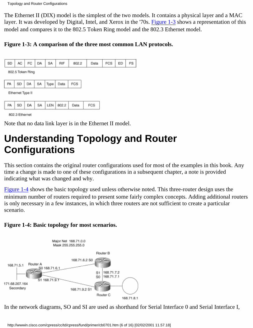
The Ethernet II (DIX) model is the simplest of the two models. It contains a physical layer and a MAClayer. It was developed by Digital, Intel, and Xerox in the '70s. Figure 1-3 shows a representation of thismodel and compares it to the 802.5 Token Ring model and the 802.3 Ethernet model.
Figure 1-3: A comparison of the three most common LAN protocols.
Note that no data link layer is in the Ethernet II model.
Understanding Topology and RouterConfigurationsThis section contains the original router configurations used for most of the examples in this book. Anytime a change is made to one of these configurations in a subsequent chapter, a note is providedindicating what was changed and why.
Figure 1-4 shows the basic topology used unless otherwise noted. This three-router design uses theminimum number of routers required to present some fairly complex concepts. Adding additional routersis only necessary in a few instances, in which three routers are not sufficient to create a particularscenario.
Figure 1-4: Basic topology for most scenarios.
In the network diagrams, SO and SI are used as shorthand for Serial Interface 0 and Serial Interface I,
Topology and Router Configurations
http://wwwin.cisco.com/cpress/cc/td/cpress/fund/primer/cb0701.htm (6 of 16) [02/02/2001 11.57.18]

respectively.
Note RouterA as used in this chapter has a connection to the "real" Cisco network via its secondaryaddress. Secondary addresses allow an interface to participate in more than one IP network at the sametime. Although the secondary address space may not be mentioned again, look for references to it in thesections on summarization, default routes, and other issues that require access to networks the routers donot know explicitly.
RouterA's Configuration
The configuration for RouterA is as follows:
!interface ethernet0ip address 168.71.5.1 255.255.255.0ip address 171.68.207.164 255.255.128 secondary!interface serial0ip address 168.71.6.1 255.255.255.0bandwidth 128!interface serial1ip address 168.71.9.1 255.255.255.0bandwidth 128!router ripnetwork 168.71.0.0passive-interface Ethernet0!ip route 0.0.0.0 0.0.0.0 Ethernet0!
This is the configuration for RouterA that is used in all future examples and scenarios unless otherwisenoted. RouterA is running RIP. It is configured with a passive interface Ethernet0 command thatprevents RIP from advertising routing updates out Ethernet0, which is a connection to Cisco's corporatenetwork.
Note The addresses used in the examples and scenarios in this book are not part of Cisco's registeredrange of IP addresses. They were chosen entirely at random and may be assigned to another organization.For more information on using registered and unregistered IP addresses, see "RFC 1918: AddressAllocation for Private Internets".
If RouterA inadvertently advertised the unregistered networks it has configured or learned from RouterBand RouterC to other Cisco routers, they might in turn advertise the networks to the Internet. If theseaddresses were actually in use by another organization, it is highly likely that some or all of the traffic forthese networks would be directed from the Internet to Cisco. Users should always be aware of where a
Topology and Router Configurations
http://wwwin.cisco.com/cpress/cc/td/cpress/fund/primer/cb0701.htm (7 of 16) [02/02/2001 11.57.18]

router will advertise its routes and, when necessary, prevent routing advertisements for certain networksto avoid connectivity problems caused by advertising false routes.
RouterB's Configuration
RouterB's configuration is very simple. RouterB only has two WAN interfaces, which is not a verycommon configuration. However, it does provide sufficient connectivity for most of the scenarios in thisbook. Adding additional interfaces would add unnecessary complexity.
RouterB has two bandwidth statements. This will affect any scenario using IGRP because IGRP used thebandwidth statement as part of the algorithm for determining routing metrics.
The configuration for RouterB is as follows:
!interface serial0ip address 168.71.6.2 255.255.255.0bandwidth 128!interface serial1ip address 168.71.7.2 255.255.255.0bandwidth 64!router ripnetwork 168.71.0.0!
RouterC's Configuration
RouterC has a Token Ring interface instead of an Ethernet interface. This interface is used todemonstrate that when routing protocols such as IP, IPX, and AppleTalk are used in conjunction withdifferent types of LANs, routers automatically take care of creating the proper layer two packet andaddressing formats for the destination interface.
RouterC also has two bandwidth statements. This will affect any scenario using IGRP because IGRPused the bandwidth statement as part of the algorithm for determining routing metrics.
The configuration for RouterC is as follows:
!interface tokenring0ip address 168.71.8.1 255.255.255.0!interface serial0ip address 168.71.7.1 255.255.255.0bandwidth 64!interface serial1ip address 168.71.9.2 255.0.0.0
Topology and Router Configurations
http://wwwin.cisco.com/cpress/cc/td/cpress/fund/primer/cb0701.htm (8 of 16) [02/02/2001 11.57.18]
bandwidth 128!router ripnetwork 168.71.0.0!
The previous sections introduced the concept of where routers can be deployed in a network and whattypes of functions they can perform. The format of IP addresses; as well as some possible issues whenbridging routable protocols such as IP, IPX, and AppleTalk; were also introduced. Finally, the basicconfigurations used for the routers in many of the scenarios presented later in this book were provided.The next section goes into more detail on how routers forward packets through a network.
Understanding What a Router DoesThe previous sections introduced some basic concepts about routers and discussed where they might bedeployed. This section presents some advanced concepts in IP routing behavior, providing examplesbased on the network topology presented in the first sections.
You now know that a router has a routing table containing network prefixes for IP network addresses itknows about. This section explains how a router uses its routing table to determine which interface itshould forward an IP datagram over in order to send it to its destination.
IP datagrams flow through a network one router at a time. Each router in a path must make its owndecision about the best interface to forward a packet over to get it to its destination. This is what is meantby hop-by-hop forwarding.
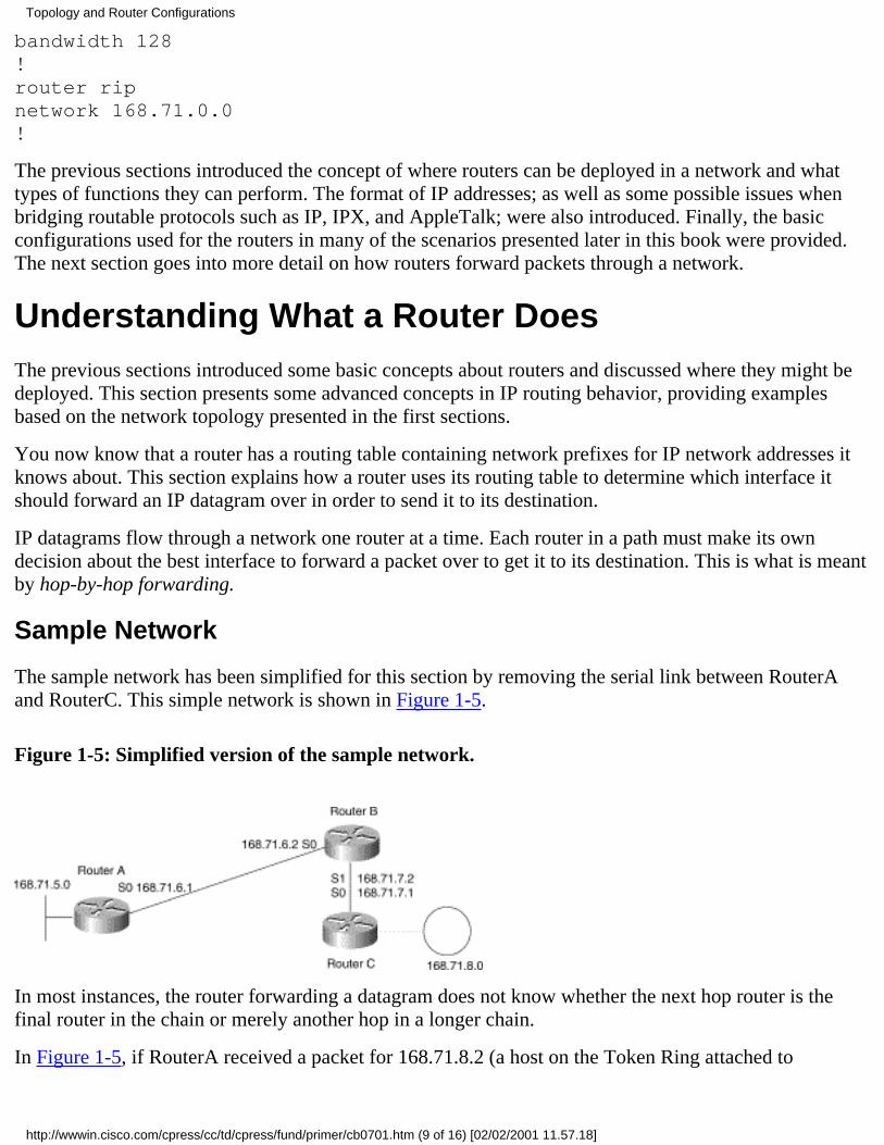
Sample Network
The sample network has been simplified for this section by removing the serial link between RouterAand RouterC. This simple network is shown in Figure 1-5.
Figure 1-5: Simplified version of the sample network.
In most instances, the router forwarding a datagram does not know whether the next hop router is thefinal router in the chain or merely another hop in a longer chain.
In Figure 1-5, if RouterA received a packet for 168.71.8.2 (a host on the Token Ring attached to
Topology and Router Configurations
http://wwwin.cisco.com/cpress/cc/td/cpress/fund/primer/cb0701.htm (9 of 16) [02/02/2001 11.57.18]
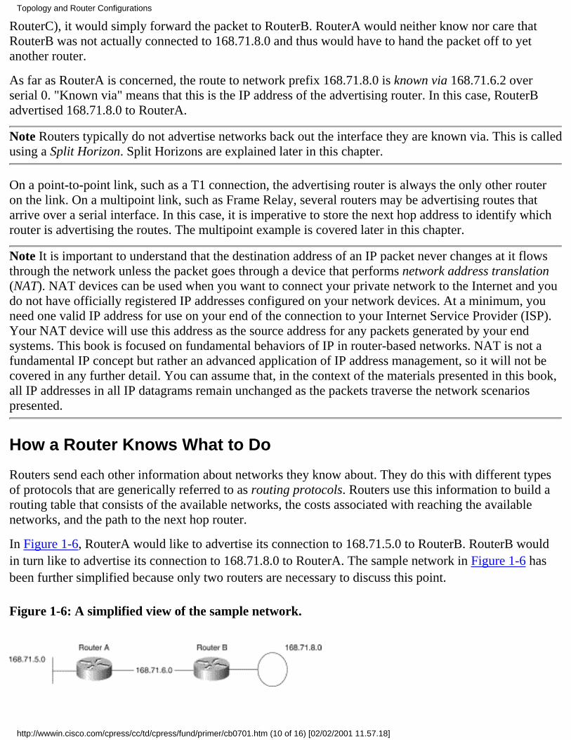
RouterC), it would simply forward the packet to RouterB. RouterA would neither know nor care thatRouterB was not actually connected to 168.71.8.0 and thus would have to hand the packet off to yetanother router.
As far as RouterA is concerned, the route to network prefix 168.71.8.0 is known via 168.71.6.2 overserial 0. "Known via" means that this is the IP address of the advertising router. In this case, RouterBadvertised 168.71.8.0 to RouterA.
Note Routers typically do not advertise networks back out the interface they are known via. This is calledusing a Split Horizon. Split Horizons are explained later in this chapter.
On a point-to-point link, such as a T1 connection, the advertising router is always the only other routeron the link. On a multipoint link, such as Frame Relay, several routers may be advertising routes thatarrive over a serial interface. In this case, it is imperative to store the next hop address to identify whichrouter is advertising the routes. The multipoint example is covered later in this chapter.
Note It is important to understand that the destination address of an IP packet never changes at it flowsthrough the network unless the packet goes through a device that performs network address translation(NAT). NAT devices can be used when you want to connect your private network to the Internet and youdo not have officially registered IP addresses configured on your network devices. At a minimum, youneed one valid IP address for use on your end of the connection to your Internet Service Provider (ISP).Your NAT device will use this address as the source address for any packets generated by your endsystems. This book is focused on fundamental behaviors of IP in router-based networks. NAT is not afundamental IP concept but rather an advanced application of IP address management, so it will not becovered in any further detail. You can assume that, in the context of the materials presented in this book,all IP addresses in all IP datagrams remain unchanged as the packets traverse the network scenariospresented.
How a Router Knows What to Do
Routers send each other information about networks they know about. They do this with different typesof protocols that are generically referred to as routing protocols. Routers use this information to build arouting table that consists of the available networks, the costs associated with reaching the availablenetworks, and the path to the next hop router.
In Figure 1-6, RouterA would like to advertise its connection to 168.71.5.0 to RouterB. RouterB wouldin turn like to advertise its connection to 168.71.8.0 to RouterA. The sample network in Figure 1-6 hasbeen further simplified because only two routers are necessary to discuss this point.
Figure 1-6: A simplified view of the sample network.
Topology and Router Configurations
http://wwwin.cisco.com/cpress/cc/td/cpress/fund/primer/cb0701.htm (10 of 16) [02/02/2001 11.57.18]

The two primary classes of routing protocols in use today are link state and distance vector, described asfollows:
A router running a link state protocol sends updates that describe the state of the links attached tothe router, the IP networks, or subnets assigned to the links and the costs associated with usingthose links. Other routers listen to these updates and then build a picture of the network's topologybased on what networks the other routers have indicated they are connected to. The metric (unit ofmeasurement) for link state protocols is typically cost based. A low-speed link costs more than ahigh-speed link in terms of performance. Paths that run over lower-cost higher-speed links arepreferred.
●
A router running a distance vector protocol sends updates that contain all of the networks that therouter knows about, not just the networks it is connected to. The advertising router increases themetric (typically a hop count) of the routes it has heard about and advertises them to the nextrouters in the path.
●
Choosing Your Routing Protocol
In general, link state routing protocols such as ISIS and OSPF are more difficult to configure andtroubleshoot than distance vector protocols, but they offer greater scalability when used in large, complexnetworks. In addition, link state protocols usually recover from network problems (converge) faster thatdistance vector protocols.
Distance vector protocols such as RIP and IGRP are easy to configure but may not work well in large,complex networks due to the length of time they can take to converge. Neither RIP V1 nor RIP V2 iscapable of taking into account the speed of a link connecting two routers. This means that they will treattwo parallel paths of unequal speeds between two routers as if they were the same speed and send thesame number of packets over each link instead of sending more over the faster link and fewer over theslower link. (IGRP does understand the speed of a link and can handle parallel links of unequal speed toa certain degree.)
Some IP routing protocols, such as OSPF, ISIS, RIP V2, and EIGRP, support concepts such as variablelength subnet masking (VLSM) and non-contiguous major networks.
In general, it is usually best to use the simplest routing protocol that meets your needs:
In a network with no redundant links or parallel paths and no requirements for VLSM ordiscontiguous major networks, RIP V1 might be perfectly suitable.
●
In a network that requires VLSM and or discontiguous major networks and that does not haveredundant links or parallel paths, RIP V2 might be perfectly suitable.
●
In a network that has redundant links or parallel paths and does not require VLSM ordiscontiguous major networks, IGRP might be perfectly suitable.
●
In a network with parallel paths and/or redundant links and that requires VLSM or discontiguousmajor networks, use either OSPF, EIGRP, or ISIS for IP.
●
This book is not intended to be an in-depth study of IP routing protocols themselves. Routing protocolsare mentioned because many fundamental behaviors of IP routing require some kind of routing protocolto be running.
Topology and Router Configurations
http://wwwin.cisco.com/cpress/cc/td/cpress/fund/primer/cb0701.htm (11 of 16) [02/02/2001 11.57.18]

The behaviors presented here apply universally to all IP routing protocols. You can configure a simplenetwork using OSPF instead of RIP and use the scenarios that follow later in this book in the exact sameway they are presented. The resulting behaviors are basically the same.
See Interconnections by Radia Perlman, published by Addison-Wesley (ISBN 0-201-56332-0) andInternetworking With TCP/IP by Douglas Comer, published by Prentice Hall (ISBN 0-13-474321-0) formore information on different types of routing protocols.
Understanding How Forwarding Decisions AreMadeIP routing is normally done on a next hop basis. For example, in Figure 1-7, RouterA may have toldRouterB about subnet 168.71.5.0. RouterB doesn't really care whether RouterA is actually attached to168.71.5.0. If RouterA says it can reach 168.71.5.0, that is sufficient for RouterB to make a forwardingdecision to send packets destined for network address 168.71.5.0 to RouterA.
Performing Longest Match Lookups
Routers take an incoming IP packet and compare it to entries in their routing tables by performing alongest match lookup. Remember that IP addresses are really 32-bit binary numbers split between anetwork section and a host section. Only the network portion is stored in a routing table.
Performing a longest match lookup in a routing table is the same as saying the following: "Find thenetwork address in the routing table with the most bits in common before a mismatch occurs with thedestination network address of the packet being routed. Do this by reading each entry in the routing tablefrom left to right, comparing each bit in sequence with the bits in the destination network address of thepacket being routed. Stop the comparison process at the bit before the first bit that doesn't match in therouting table entry being compared."
Figure 1-7: An example of a simple routing table for RouterB.
Longest Match Lookup---A Simple Example
Note Start with the binary number 11111100. Compare it to the following binary numbers: (a) 11111000,
Topology and Router Configurations
http://wwwin.cisco.com/cpress/cc/td/cpress/fund/primer/cb0701.htm (12 of 16) [02/02/2001 11.57.19]

(b) 11110000, and (c) 11100000. Which is the longest match?
Note The answer is (a). The original binary number starts with a string of six 1s, followed by two 0s. (a)starts with five 1s, followed by three 0s, so it has the longest matching number of bits before a mismatch.
Note Routers typically store entries in their tables in descending order. In this example, the numberswould be stored in the order: (a), (b), (c).
Note If a router were comparing these numbers, it would have started with (a) and stored in memory howclosely (a) matched the number being compared (11111100) before a mismatched bit occurred.
Note The router would then proceed to do the same comparison for (b). The router would have realizedthat (a) was a better match than (b) because (a) had five bits in common before a mismatch, whereas (b)had only four.
Note The router would never have gotten around to checking (c) because it would know that numbers arestored in descending order and that (c) had to be a smaller number than (b) and therefore could not be abetter match.
See the section on longest match lookups using VLSM in "Discontiguous Networks, Summarization, andSubnet 0." VLSM is also explained in Chapter 3.
Entries in a routing table are the network addresses that the router knows about. It is common practice torefer to an entry in a routing table as a route. Therefore, saying that RouterB has a network entry in itsrouting table for network 168.71.5.0 is synonymous with saying "RouterB has a route to 168.71.5.0."This book uses both methods when discussing the contents of a router's routing table.
Routers ignore the host section of the destination address. They use only the network section whenperforming a longest match lookup. Routers know how addresses should be broken down because theystore the subnet mask associated with each route in its routing table.
Note Routing tables normally include the subnet masks associated with the network addresses, as well asthe network addresses themselves. Subnet masks are not given in the routing table in Figure 1-8 so that itis easier to view. For reference, the mask for these routes is 255.255.255.0.
If a router finds a suitable match in its table for the network address of a packet it is trying to forward, ithas what is sometimes referred to as an explicit match. In other words, the information in the routingtable indicates explicitly where to send the packet.
If no explicit route is available, the router may choose to forward the packet to a gateway of last resort.This is covered in more detail in "Using IP Unnumbered and VLSM," in the section on gateways. InFigure 1-7, RouterB received a packet destined for 168.71.5.1.
The longest match in the routing table indicates that 168.71.5.0 is known via serial 0, with a next hop of168.71.6.1. In this case, the next hop address is redundant because the serial link is point to point. Thereis only one router to forward this packet to. Remember that the actual destination IP address in the packet
Topology and Router Configurations
http://wwwin.cisco.com/cpress/cc/td/cpress/fund/primer/cb0701.htm (13 of 16) [02/02/2001 11.57.19]

does not change. It remains 168.71.5.1.
Forwarding Decisions for Multipoint Interfaces
Figure 1-8 shows how the next hop interface of serial 0 is not sufficient for forwarding the packet to168.71.5.1 accurately. The further distinction of a next hop IP address eliminates the ambiguity of onlypointing to the serial interface. In this case, RouterB knows that the next hop is out serial 0 to the nexthop address of 168.71.6.1. RouterB will have a Frame Relay map entry on serial 0 that indicates theappropriate DLCI (100) to send the packet to.
Figure 1-8: How forwarding decisions are made for multipoint interfaces.
For Frame Relay, the DLCI address performs the same function as a MAC address on an Ethernetnetwork. Frame Relay is a layer two protocol. Therefore, when a Frame Relay switch forwards an IPdatagram encapsulated in a Frame Relay layer two frame, it does so by reading the layer two destinationDLCI address contained in the frame.
The Frame Relay network switches the frame through the network and finally delivers it to RouterA.RouterA can then forward the datagram on to the ultimate host. See Frame Relay Principles andApplications by Philip Smith, published by Addison-Wesley (ISBN 0-201-62400-1), for moreinformation on Frame Relay.
The Frame Relay map entry for IP address 168.71.6.1 to DLCI 100 is essentially an ARP entry for thelayer two and layer three protocol addresses. It is similar to an Ethernet MAC address to IP address ARPentry:
RouterB#show frame-relay mapSerial0 (up): ip 168.71.6.1 dlci 100(0x64,0x1840), static, broadcast, CISCORouterB#
The Address Resolution Protocol (ARP) is used to resolve layer three (network) addresses to layer two(MAC) addresses so that frames can be forwarded to a particular host directly. If end systems were notable to store entries that mapped these two addresses, all frames would have to be broadcast at the MAC
Topology and Router Configurations
http://wwwin.cisco.com/cpress/cc/td/cpress/fund/primer/cb0701.htm (14 of 16) [02/02/2001 11.57.19]

level. In addition, each end system would have to open every frame and de-encapsulate it to the networklayer to see whether the frame's network layer address matched its own network layer address.
End Systems Sending Packets to Other Subnets
Before a router can even become involved in forwarding a packet from an end station, the end stationmust figure out how to get the packet to the router in the first place.
When an end system wants to send an IP packet to another end system, it compares the destination IPaddress with its own address. If the destination network address is within the same subnet (on the samelocal cable), the originating end station will ARP for the destination end system.
If the originating end system determines that the destination end system is on a different cable because ithas a different subnet (network) address, it will send the packet to the MAC (cable address) of itsgateway and the IP address of the destination end system.
In Figure 1-9, end system A wants to send a PING to end system B. End system A determines that endsystem B is on a different cable segment because the destination IP address is on a different subnet of168.71.0.0. End system A is on subnet 168.71.5.0, and end system B is on subnet 168.71.8.0.
End system A has 168.71.5.2 configured as its gateway address. End system A will ARP for the MACaddress of 168.71.5.2 so that it can use this address as the MAC address for delivering packets to168.71.8.1. The layer two (MAC) addresses are specific to the link to which they are attached. The layerthree (IP addresses) are end to end. The layer two addresses for the serial links have been omitted forclarity.
Figure 1-9: End system A sends a PING to end system B.
The IP address 168.71.5.2 and the MAC address 0000.0c01.8793 both belong to RouterA's Ethernet 0interface. The IP address 168.71.8.2 and the MAC address 0000.0f00.8684 both belong to RouterB'sToken Ring 0 interface. Gateways are covered in more detail in "Default Routing."
Note If you have a PC running TCP/IP, you may be able to see this for yourself. At a DOS prompt, typeC:\> arp -a.
Note You should see the IP address and MAC address of your IP gateway. You will probably not seeentries for systems that are not on your subnet because your PC is sending these datagrams in frames thathave the MAC address of your IP gateway.
Topology and Router Configurations
http://wwwin.cisco.com/cpress/cc/td/cpress/fund/primer/cb0701.htm (15 of 16) [02/02/2001 11.57.19]
Note Entries for systems on your own subnet will have their own MAC addresses associated with theirIP addresses. If you do not see any entries for systems on your subnet, try the following command at aDOS prompt: C:\>ping 255.255.255.255. This is the IP broadcast address. Then try C:\> arp -a again. Ifother IP hosts are on your subnet, they may show up in your ARP table.
SummaryRouter-based internetworking is a very complex subject. Many of the concepts are interrelated anddifficult to understand on their own. This chapter has introduced some of the terms used, as well as somefundamental concepts that provide the foundation upon which the remainder of this book is built. Thenext chapter introduces the concept of convergence, which allows routers to cope with changes innetwork topologies.
Posted: Wed Mar 3 09:59:39 PST 1999Copyright 1989-1999©Cisco Systems Inc.Copyright © 1997 Macmillan Publishing USA, a Simon & Schuster Company
Topology and Router Configurations
http://wwwin.cisco.com/cpress/cc/td/cpress/fund/primer/cb0701.htm (16 of 16) [02/02/2001 11.57.19]
Table of Contents
Routing Metrics and Distances
Primary Activities of ConvergenceViewing the Invalid Timers in a Routing TableViewing an Expired Invalid Timer in a Routing TableRouter Still Uses a Path
Understanding ConvergenceParallel Paths
The Effect of Parallel Paths on ConvergenceLooking at Parallel Paths in a Routing Table
Convergence in Action
The Routing Table After ConvergenceStep-by-Step Review of Convergence
Debug Messages and RealityWhen Holddown Is InitiatedUnderstanding Parallel Paths and Their Effect on Packet Forwarding
Process Switching Versus Fast SwitchingConfiguring Process SwitchingConfiguring Fast Switching
Understanding the Role of Split HorizonRouting Advertisements with Split Horizon EnabledRouting Advertisements with Split Horizon DisabledRouting Loops Caused by Disabling Split HorizonLoss of a Connected Route Versus a Dynamic RouteSplit Horizon's Effect on Multipoint WAN InterfacesUsing Subinterfaces to Avoid Problems Caused by Split Horizon
Poison Reverse and Triggered UpdatesIGRP Routing Metrics (Variables) and Cisco Administrative Distances
IGRP Metrics (Variables)Administrative DistancesRunning Multiple Routing Protocols ConcurrentlyAltering IGRP's Bandwidth and Delay Variables
Problems with Manipulating the Delay VariableUnderstanding the Effects of Manipulating the Delay VariableUnderstanding the Effects of Manipulating the Bandwidth Variable
Calculating IGRP Metrics
Summary
Routing Metrics and Distances
http://wwwin.cisco.com/cpress/cc/td/cpress/fund/primer/cb0702.htm (1 of 38) [02/02/2001 11.57.53]

Routing Metrics and DistancesThis chapter focuses on convergence and parallel paths, primarily discussing their interaction with routing metrics anddistances.
Convergence is the process routers go through when a route (network) or group of routes has become unavailable due to a linkgoing down in the network or extreme packet loss on a link. This loss results in the routers flushing the lost routes and listeningto see whether other routes are available. Routers usually store only the best route to a network in their routing tables. Other,higher-cost, routes may exist, but the router ignores them if it believes that the better route still exists.
In the example in Figure 2-1, RouterA converges on a new path to 168.71.8.1 because the link between RouterA and RouterChas failed.
Figure 2-1: RouterA has to converge on a new path because the link to RouterC has gone down.
Primary Activities of ConvergenceConvergence involves four primary activities: update, invalid, holddown, and flush, which are explained in Table 2-1. Thefollowing example, which uses the show ip protocol command at the command prompt of RouterA, shows the default timersused by RIP. These are the timers that a Cisco router uses to control the way RIP reacts to changes in its routing table. It ispossible to override these defaults by using the timers basic command. See the Cisco command reference for the version ofIOS you are using for more information on this command.
Note The timers basic command should be used with caution. Inappropriate use of this command can have a catastrophiceffect on the IP routing functionality of your router.
RouterA#show ip protocolRouting Protocol is "rip" Sending updates every 30 seconds, next due in 27 seconds Invalid after 180 seconds, hold down 180, flushed after 240..output deleted.RouterA#
Routing Metrics and Distances
http://wwwin.cisco.com/cpress/cc/td/cpress/fund/primer/cb0702.htm (2 of 38) [02/02/2001 11.57.53]
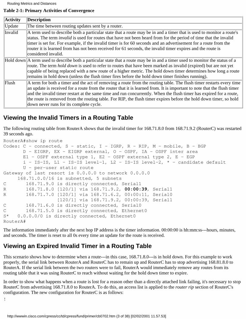
Table 2-1: Primary Activities of Convergence
Activity DescriptionUpdate The time between routing updates sent by a router.Invalid A term used to describe both a particular state that a route may be in and a timer that is used to monitor a route's
status. The term invalid is used for routes that have not been heard from for the period of time that the invalidtimer is set for. For example, if the invalid timer is for 60 seconds and an advertisement for a route from therouter it is learned from has not been received for 61 seconds, the invalid timer expires and the route isconsidered invalid.
Hold down A term used to describe both a particular state that a route may be in and a timer used to monitor the status of aroute. The term hold down is used to refer to routes that have been marked as invalid (expired) but are not yetcapable of being replaced with a new route of a higher metric. The hold down timer determines how long a routeremains in hold down (unless the flush timer fires before the hold down timer finishes running).
Flush A term for both a timer and the act of removing a route from the routing table. The flush timer restarts every timean update is received for a route from the router that it is learned from. It is important to note that the flush timerand the invalid timer restart at the same time and run concurrently. When the flush timer has expired for a route,the route is removed from the routing table. For RIP, the flush timer expires before the hold down timer, so holddown never runs for its complete cycle.
Viewing the Invalid Timers in a Routing Table
The following routing table from RouterA shows that the invalid timer for 168.71.8.0 from 168.71.9.2 (RouterC) was restarted39 seconds ago.
RouterA#show ip routeCodes: C - connected, S - static, I - IGRP, R - RIP, M - mobile, B - BGP D - EIGRP, EX - EIGRP external, O - OSPF, IA - OSPF inter area E1 - OSPF external type 1, E2 - OSPF external type 2, E - EGP i - IS-IS, L1 - IS-IS level-1, L2 - IS-IS level-2, * - candidate default U - per-user static routeGateway of last resort is 0.0.0.0 to network 0.0.0.0 168.71.0.0/16 is subnetted, 5 subnetsC 168.71.9.0 is directly connected, Serial1R 168.71.8.0 [120/1] via 168.71.9.2, 00:00:39, Serial1R 168.71.7.0 [120/1] via 168.71.6.2, 00:00:11, Serial0 [120/1] via 168.71.9.2, 00:00:39, Serial1C 168.71.6.0 is directly connected, Serial0C 168.71.5.0 is directly connected, Ethernet0S* 0.0.0.0/0 is directly connected, Ethernet0RouterA#
The information immediately after the next hop IP address is the timer information. 00:00:00 is hh:mm:ss---hours, minutes,and seconds. The timer is reset to all 0s every time an update for the route is received.
Viewing an Expired Invalid Timer in a Routing Table
This scenario shows how to determine when a route---in this case, 168.71.8.0---is in hold down. For this example to workproperly, the serial link between RouterA and RouterC has to remain up and RouterC has to stop advertising 168.81.8.0 toRouterA. If the serial link between the two routers were to fail, RouterA would immediately remove any routes from itsrouting table that it was using RouterC to reach without waiting for the hold down timer to expire.
In order to show what happens when a route is lost for a reason other than a directly attached link failing, it's necessary to stopRouterC from advertising 168.71.8.0 to RouterA. To do this, an access list is applied to the router rip section of RouterC'sconfiguration. The new configuration for RouterC is as follows:
!
Routing Metrics and Distances
http://wwwin.cisco.com/cpress/cc/td/cpress/fund/primer/cb0702.htm (3 of 38) [02/02/2001 11.57.53]
interface tokenring0ip address 168.71.8.1 255.255.255.0!interface serial0ip address 168.71.7.1 255.255.255.0bandwidth 64!interface serial1ip address 168.71.9.2 255.0.0.0bandwidth 128!router ripnetwork 168.71.0.0distribute-list 1 out serial1!access-list 1 deny 168.71.8.0 0.0.0.0access-list 1 permit 0.0.0.0 255.255.255.255!
Note Refer to your Cisco IOS documentation for an explanation of access list configuration and use. The concept of usingaccess lists to filter routing updates is explained in more detail in "Default Routing."
In the following routing table from RouterA, you can see that RouterA's invalid timer has expired for 168.71.8.0 and that theroute is marked "possibly down, routing via 168.71.9.2, Serial1." At this point, the route is considered to be in holddown, andthe 180-second holddown is now running.
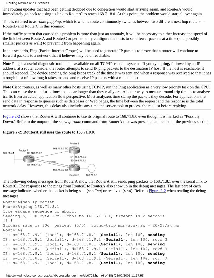
There is another path via RouterB by which RouterA can reach 168.71.8.0. RouterA should converge on this path after itfinally gives up on the original route via RouterC. In the meantime, RouterA will continue to use this route to reach 168.71.8.0.
RouterA#show ip routeCodes: C - connected, S - static, I - IGRP, R - RIP, M - mobile, B - BGP D - EIGRP, EX - EIGRP external, O - OSPF, IA - OSPF inter area E1 - OSPF external type 1, E2 - OSPF external type 2, E - EGP i - IS-IS, L1 - IS-IS level-1, L2 - IS-IS level-2, * - candidate default U - per-user static routeGateway of last resort is 0.0.0.0 to network 0.0.0.0 168.71.0.0/16 is subnetted, 5 subnetsC 168.71.9.0 is directly connected, Serial1R 168.71.8.0/24 is possibly down, routing via 168.71.9.2, Serial1R 168.71.7.0 [120/1] via 168.71.6.2, 00:00:24, Serial0C 168.71.6.0 is directly connected, Serial0C 168.71.5.0 is directly connected, Ethernet0S* 0.0.0.0/0 is directly connected, Ethernet0RouterA#
RouterA will continue to use this route to forward packets destined for subnet 168.71.8.0. This concept is explained in the nextscenario.
Note If a network administrator discovers that a route is in holddown, he or she can attempt to clear the route manually tospeed up convergence if a different path is available. If no other path is available, this command will probably not help resolvethe connectivity loss problem created by the route going into holddown. The syntax for this command, using the route fromthis scenario, is as follows:
RouterA#clear ip route 168.71.8.0
Note This command was not used in this section because it would have invalidated the scenario being presented. This
Routing Metrics and Distances
http://wwwin.cisco.com/cpress/cc/td/cpress/fund/primer/cb0702.htm (4 of 38) [02/02/2001 11.57.53]

command can be used on routes that are in holddown with no negative effect. If it is used on an active route (one that is not inholddown), temporary connectivity loss can occur. It is best to experiment with this command in a lab environment tounderstand how it will affect IP connectivity before using it in a live environment.
Note The administrator can also use the traceroute command to find a router that has a connection to the network that is inholddown. Depending on the topology of the network and the status of the routing tables in the routers that the traceroutecommand encounters, it may actually end up at the router that was advertising the route that has gone into holddown.However, it is not really necessary to find the exact router that was sending the original route. Any router connected to thesame network can be used to investigate what the problem is and possibly resolve it. It could be something like an Ethernetsegment with excessive collisions that is constantly resetting or a beaconing Token Ring segment. The traceroute command isavailable on Cisco routers and most other hosts that use TCP/IP. The syntax of this command on a Cisco router's commandprompt is as follows:
RouterA#traceroute 168.71.8.0
Note In Figure 2-1, the traceroute 168.71.8.0 command from RouterA would end up at RouterC using the path via RouterBafter RouterA had converged on the new path. An investigation of RouterC would have turned up the fact that someone hadconfigured an access list against RIP. The TraceRoute utility is described in more detail in "IP Troubleshooting Scenarios,"More information on TraceRoute can be found in RFC 1393 as well (see Appendix A, "RFCs").
Router Still Uses a Path
During the time RouterA has its route to 168.71.8.0 in holddown, it continues to forward any packets it receives that aredestined for subnet 168.71.8.0 to RouterC. This is standard behavior for a router running RIP, as well as for many other IProuting protocols.
One of the reasons for having routing protocols behave this way is based on the following assumption:
Temporary packet loss due to using routes to networks that might not be viable is better than immediately accepting a lessdesirable route to the destination network.
In this scenario, the less desirable path would be for RouterA to reach 168.71.8.0 via RouterB. If 168.71.8.0 went intoholddown in RouterA because of congestion on the link between RouterA and RouterC---which caused the packets with therouting updates to be dropped---packets from sessions between hosts on subnets 168.71.5.0 and 168.71.8.0 over the same linkshould be dropped as well.
By allowing these packets to be dropped instead of sending them via the less desirable path, RouterA and RouterC are givingthe hosts a chance to react to the dropped packets by sending fewer packets at a time---and perhaps even sending smallerpackets. This requires that either the applications in use or their underlying protocols keep track of packet loss and react in anetwork-friendly fashion.
Note In networks with very large routing tables, the updates might be split between multiple packets. If you have recentlyadded several new routes and are having problems with these routes not being learned by other routers or other routes thatwere once stable suddenly disappearing---particularly over low-speed serial links---it is very probable that the same packets atthe end of each update are getting lost. Routes are usually advertised in descending order: 134.67.0.0 would be sent before120.34.0.0. If your lowest numbered routes are having problems, this is most likely what is happening.
If RouterA immediately accepted the less desirable route to 168.71.8.0 as soon as the invalid timer for 168.71.8.0 expired andforwarded all traffic to 168.71.8.0 over it, congestion on the more desirable path between RouterA and RouterC would cease tobe a problem.
Note Remember that holddown is both the name of a timer that routing protocols use and the name of a function. Theholddown timer, which is 180 seconds for RIP, starts when the invalid timer expires. The holddown function is the same for allIP routing protocols. It is used to prevent a new, higher-cost (less desirable) route from being accepted for a route that has beenmarked invalid for the period of the holddown timer.
Routing Metrics and Distances
http://wwwin.cisco.com/cpress/cc/td/cpress/fund/primer/cb0702.htm (5 of 38) [02/02/2001 11.57.53]
The routing updates that had been getting dropped due to congestion would start arriving again, and RouterA wouldimmediately go back to using its link to RouterC to reach 168.71.8.0. At this point, the problem would start all over again.
This is referred to as route flapping, which is when a route continuously switches between two different next hop routers---RouterB and RouterC in this scenario.
If the traffic pattern that caused this problem is more than just an anomaly, it will be necessary to either increase the speed ofthe link between RouterA and RouterC or permanently configure the hosts to send fewer packets at a time (and possiblysmaller packets as well) to prevent it from happening again.
In this scenario, Ping (Packet Internet Groper) will be used to generate IP packets to prove that a router will continue toforward packets to a network that it believes may be unreachable.
Note Ping is a useful diagnostic tool that is available on all TCP/IP-capable systems. If you type ping, followed by an IPaddress, at a router console, the router attempts to send IP ping packets to the destination IP host. If the host is reachable, itshould respond. The device sending the ping keeps track of the time it was sent and when a response was received so that it hasa rough idea of how long it takes to send and receive IP packets with a remote host.
Note Cisco routers, as well as many other hosts using TCP/IP, run the Ping application as a very low priority task on the CPU.This can cause the round-trip times to appear longer than they really are. A better way to measure round-trip time is to analyzetraffic from an actual application flow perspective. Most analyzers time stamp the packets they decode. For applications thatsend data in response to queries such as databases or Web pages, the time between the request and the response is the totalnetwork delay. However, this delay also includes any time the server took to process the request before replying.
Figure 2-2 shows that RouterA will continue to use its original route to 168.71.8.0 even though it is marked as "PossiblyDown." Refer to the output of the show ip route command from RouterA that was presented at the end of the previous section.
Figure 2-2: RouterA still uses the route to 168.71.8.0.
The following debug messages from RouterA show that RouterA still sends ping packets to 168.71.8.1 over the serial link toRouterC. The responses to the pings from RouterC to RouterA also show up in the debug messages. The last part of eachmessage indicates whether the packet is being sent (sending) or received (rcvd). Refer to Figure 2-2 when reading the debugmessages.
RouterA#deb ip packetRouterA#ping 168.71.8.1Type escape sequence to abort.Sending 5, 100-byte ICMP Echos to 168.71.8.1, timeout is 2 seconds:!!!!!Success rate is 100 percent (5/5), round-trip min/avg/max = 20/23/24 msRouterA#IP: s=168.71.9.1 (local), d=168.71.8.1 (Serial1), len 100, sendingIP: s=168.71.8.1 (Serial1), d=168.71.9.1 (Serial1), len 104, rcvd 3IP: s=168.71.9.1 (local), d=168.71.8.1 (Serial1), len 100, sendingIP: s=168.71.8.1 (Serial1), d=168.71.9.1 (Serial1), len 104, rcvd 3IP: s=168.71.9.1 (local), d=168.71.8.1 (Serial1), len 100, sendingIP: s=168.71.8.1 (Serial1), d=168.71.9.1 (Serial1), len 104, rcvd 3IP: s=168.71.9.1 (local), d=168.71.8.1 (Serial1), len 100, sending
Routing Metrics and Distances
http://wwwin.cisco.com/cpress/cc/td/cpress/fund/primer/cb0702.htm (6 of 38) [02/02/2001 11.57.53]

IP: s=168.71.8.1 (Serial1), d=168.71.9.1 (Serial1), len 104, rcvd 3IP: s=168.71.9.1 (local), d=168.71.8.1 (Serial1), len 100, sendingIP: s=168.71.8.1 (Serial1), d=168.71.9.1 (Serial1), len 104, rcvd 3RouterA
In the previous router output, you can see that RouterA sent five pings to a host on the 168.71.8.0 subnet; in this case, the hostis RouterC's Token Ring interface. The pings were successful, as indicated by the exclamation points (!). This proves that eventhough RouterA thought its route to 168.71.8.0 was no longer valid, it still used it to forward packets.
Note The preceding router output also shows the use of the debug ip packet command. When the router is Process SwitchingIP packets, this causes the router to display debug information for every IP packet that it either sends or receives. ProcessSwitching is explained later in this chapter in the section on Process Switching versus Fast Switching. This command shouldbe used with extreme care. It can cause a heavily loaded router to stop functioning. It is possible to use access lists inconjunction with some debugging commands (including debug ip packet) to reduce their performance impact on a router,which is explained in "Default Routing." If you are using a Telnet connection to a router, you need to enter the terminalmonitor command in order to view the output of debug commands. You must do this for every new Telnet session. Check theversion of Cisco IOS you are running to find out its default behavior for sending debug messages.
Understanding ConvergenceRecall that convergence involves four primary activities: update, invalid, holddown, and flush. These activities come into playany time a router experiences a change in its routing table, including when the router is powered on. This section includes ascenario that shows the process of convergence by causing RouterC to cease sending routing updates to RouterA. This sectionalso introduces the concept of parallel paths in a routing table and discusses some of the issues they can create.
Parallel Paths
When a router has two or more routes to the same network with the same metric, these routes can be thought of as having anequal cost. The term parallel paths is a just a common way to refer to occurrences of equal-cost routes in a routing table.
The Effect of Parallel Paths on Convergence
If a router had two or more equal-cost paths (routes) to a network, it may use them concurrently. If a router loses one or moreof the parallel paths, it will continue to use the paths that are still available. RouterA in Figure 2-3 has two equal-cost paths to168.71.7.0. If it loses the route via serial 0, it can continue to use the route via serial 1. Convergence in this situation is simplya matter of removing any references in the routing table to the route that has ceased to exist.
Figure 2-3: Parallel paths enable a router to continue to use whatever paths are available when some paths are down.
The arrows in Figure 2-3 show that RouterA has two routes (parallel paths) to subnet 168.71.7.0.
Looking at Parallel Paths in a Routing Table
The following routing table from RouterA has the two parallel paths, which are shown here in bold:
RouterA#show ip routeCodes: C - connected, S - static, I - IGRP, R - RIP, M - mobile, B - BGP D - EIGRP, EX - EIGRP external, O - OSPF, IA - OSPF inter area E1 - OSPF external type 1, E2 - OSPF external type 2, E - EGP i - IS-IS, L1 - IS-IS level-1, L2 - IS-IS level-2, * - candidate defaultGateway of last resort is 0.0.0.0 to network 0.0.0.0
Routing Metrics and Distances
http://wwwin.cisco.com/cpress/cc/td/cpress/fund/primer/cb0702.htm (7 of 38) [02/02/2001 11.57.53]

168.71.0.0 255.255.255.0 is subnetted, 5 subnetsC 168.71.9.0 is directly connected, Serial1R 168.71.8.0 [120/1] via 168.71.9.2, 00:00:15, Serial1R 168.71.7.0 [120/1] via 168.71.6.2, 00:00:00, Serial0 [120/1] via 168.71.9.2, 00:00:15, Serial1C 168.71.6.0 is directly connected, Serial0C 168.71.5.0 is directly connected, Ethernet0 171.68.0.0 is variably subnetted, 2 subnets, 2 masksC 171.68.207.128 255.255.255.128 is directly connected, Ethernet0S 171.68.0.0 255.255.0.0 [1/0] via 171.68.207.129S* 0.0.0.0/0 is directly connected, Ethernet0RouterA#
When parallel (equal-cost) paths are available to a network, the routing table displays the first entry with a character prefixindicating how it knows about the route and omits this prefix for all other paths to the same network. In the previous example,RouterA's routing table indicates that it has two paths to 168.71.7.0. Both are learned via RIP; however, only one of them hasthe R tag that indicates it is a RIP-derived route. The R is assumed for the other route. The first route has a next hop of168.71.6.2. The second route has a next hop of 168.71.9.2. Refer to Figure 2-3 to compare the network diagram with theprevious routing table.
The codes section of the routing table shows what routing protocols the various prefixes are used for.
Convergence in Action
This section presents a scenario that explains what happens when a router running RIP has to converge on a new route becausean existing route has ceased to be advertised by the router it was originally learned from.
Here is a review of the default timers RIP uses. These timers are reflected in the behavior of RIP in this scenario.
RouterA#show ip protocolRouting Protocol is "rip" Sending updates every 30 seconds, next due in 27 seconds Invalid after 180 seconds, hold down 180, flushed after 240..Output deleted.RouterA#
The access list that was applied in the previous section to stop RouterC from advertising 168.71.8.0 has been modified to alsoblock subnet 168.71.7.0. It has been applied to RouterC again for this section.
This is RouterA's routing table before the invalid timer for the route to 168.71.8.0 expires. Notice that the invalid timer isalready at 39 seconds. This means that the access list was applied at least nine seconds ago.
RouterA#show ip routeCodes: C - connected, S - static, I - IGRP, R - RIP, M - mobile, B - BGP D - EIGRP, EX - EIGRP external, O - OSPF, IA - OSPF inter area E1 - OSPF external type 1, E2 - OSPF external type 2, E - EGP i - IS-IS, L1 - IS-IS level-1, L2 - IS-IS level-2, * - candidate default U - per-user static routeThe gateway of last resort is 0.0.0.0 to network 0.0.0.0: 168.71.0.0/16 is subnetted, 5 subnetsC 168.71.9.0 is directly connected, Serial1R 168.71.8.0 [120/1] via 168.71.9.2, 00:00:39, Serial1R 168.71.7.0 [120/1] via 168.71.6.2, 00:00:11, Serial0 [120/1] via 168.71.9.2, 00:00:39, Serial1C 168.71.6.0 is directly connected, Serial0
Routing Metrics and Distances
http://wwwin.cisco.com/cpress/cc/td/cpress/fund/primer/cb0702.htm (8 of 38) [02/02/2001 11.57.53]

C 168.71.5.0 is directly connected, Ethernet0S* 0.0.0.0/0 is directly connected, Ethernet0RouterA#
RouterA's invalid timers for the routes it has learned from RouterC will expire in 141 seconds.
Assume that 141 seconds have just passed. The following debug messages from RouterA show what happens when the invalidtimers for the routes it has learned from RouterC fire.
RouterA#debug ip routingRouterA#sh clock20:33:30.246 UTC Fri Aug 2 1996RouterA#debug ip routingAug 2 20:36:45: RT: flushed route to 168.71.8.0 via 168.71.9.2 (Serial1)Aug 2 20:36:45: RT: no routes to 168.71.8.0, entering holddownAug 2 20:36:45: RT: flushed route to 168.71.7.0 via 168.71.9.2 (Serial1)Aug 2 20:37:41: RT: garbage collecting entry for 168.71.8.0Aug 2 20:37:50: RT: add 168.71.8.0/24 via 168.71.6.2, rip metric [120/2]RouterA#
Notice in the debug that RouterA did not add a new route to 168.71.7.0 after removing the old routes from RouterC. This isbecause RouterA originally had two parallel paths to 168.71.7.0. The convergence process in this scenario involved removingany references to routes learned from RouterC and installing a route to 168.71.8.0 via RouterB.
Note The preceding router output introduced the debug ip routing command. The debug ip routing command causes the routerto create a message any time the status of the routing table changes. This change can be the addition of a new route or a changein the status of an existing route.
The Routing Table After Convergence
The following routing table from RouterA shows its new converged state. RouterA is now using RouterB to route packets to168.71.8.0. Remember that RouterA did not lose its original route to 168.71.8.0 because there was a problem with RouterC'sToken Ring interface. It lost the route because the access list applied to RouterC's configuration caused RouterC to stopadvertising all of its routes to RouterA. RouterC never stopped advertising routes to RouterB.
RouterA#show ip routeCodes: C - connected, S - static, I - IGRP, R - RIP, M - mobile, B - BGP D - EIGRP, EX - EIGRP external, O - OSPF, IA - OSPF inter area E1 - OSPF external type 1, E2 - OSPF external type 2, E - EGP i - IS-IS, L1 - IS-IS level-1, L2 - IS-IS level-2, * - candidate default U - per-user static routeGateway of last resort is 0.0.0.0 to network 0.0.0.0 168.71.0.0/16 is subnetted, 5 subnetsC 168.71.9.0 is directly connected, Serial1R 168.71.8.0 [120/2] via 168.71.6.2, 00:00:05, Serial0R 168.71.7.0 [120/1] via 168.71.6.2, 00:00:06, Serial0C 168.71.6.0 is directly connected, Serial0C 168.71.5.0 is directly connected, Ethernet0S* 0.0.0.0/0 is directly connected, Ethernet0RouterA#
Notice the different metric in the partial routing tables shown here. When the route for 168.71.8.0 changed from RouterC toRouterB, the metric went from 1 to 2. The metric is the second number inside the []s. For example, [120/3] means a metric of3. The next two bullet points illustrate the change from one metric to another.
The original route via 168.71.9.2 has a metric of 1, as follows:●
RouterA#show ip route 168.71.8.0 (output edited for clarity)R 168.71.8.0 [120/1] via 168.71.9.2, 00:00:39, Serial1
Routing Metrics and Distances
http://wwwin.cisco.com/cpress/cc/td/cpress/fund/primer/cb0702.htm (9 of 38) [02/02/2001 11.57.53]

The metric changed to 2 after losing the original route via 168.71.9.2 and replacing it with the new route via 168.71.6.2:●
RouterA#show ip route 168.71.8.0 (output edited for clarity)R 168.71.8.0 [120/2] via 168.71.6.2, 00:00:05, Serial0
Keeping track of the metrics and next hop addresses in a routing table will help you when you are troubleshooting an IProuting problem. You will be able to determine the different routes your traffic is taking and compare them to your networkdiagrams.
Step-by-Step Review of Convergence
The following steps occurred at or close to the same time RouterC stopped advertising routes to RouterA. Refer to the timestamps on the previous debug messages.
1. Aug 2 20:33:45: Invalid timer restarted after the last routing update was received from RouterC. You know that thiswas the approximate time the last update was received because the invalid timer runs for 180 seconds (three minutes)before firing, and it fires at 20:36:45.
2. Aug 2 20:33:45: Flush timer restarted after the last routing update was received from RouterC. You know that this isthe approximate time because the flush timer is reset every time the invalid timer is reset. The flush timer and the invalidtimer run concurrently.
3. Aug 2 20:36:45: Invalid timer fires for networks that RouterA was using RouterC to reach.
4. Aug 2 20:36:45: Hold down timer starts for networks that RouterA was using RouterC to reach.
5. Aug 2 20:37:41: Flush timer fires and terminates holddown timer for networks that RouterA was using RouterC toreach. This is allowed because the flush timer overrides the hold down timer.
6. Hold down didn't start until 20:36:45. The hold down timer is 180 seconds (three minutes); therefore, it should haverun until 20:39:45.
7. Garbage collecting is Cisco-speak for totally removing (flushing) any remaining references to the routes in question.
8. Aug 2 20:37:50: RouterA receives RouterB's routing update and installs a route to 168.71.8.0. In this case, the updatefrom RouterB arrived nine seconds after RouterA's flush timer fired.
Note Because RIP only sends updates every 30 seconds, it could have taken anywhere from .01 second to 29.99 seconds(rounding to the nearest hundredth second) for RouterB's next update to arrive so that RouterA could accept the new route.
Note The total estimated time of convergence (from last update received to accepting the higher cost route) in this scenariowas equal to the following:
Note 20:37:50 (finish)
Note -20:33:45 (start)
Note 00:04:05 Time to converge
You may have noticed that the times shown in the debug do not match the exact default timer intervals for RIP. This is becausethe router might take some time to get around to running the task. A RIP timer might expire and raise a flag to be serviced, butit might not be serviced for a few seconds after raising the flag. This is normal behavior and should be considered whendetermining maximum possible convergence times. Note that the update timer will vary by a random amount, helping preventall routers from sending their updates at exactly the same time. RFC 1058, which is discussed in Appendix A, explains RIPtimers in more detail.
It is important to note that RouterB was advertising 168.71.8.0 and 168.71.7.0 to RouterA every 30 seconds. RouterA wasinitially ignoring RouterB's advertisements for 168.71.8.0 because the metric from RouterB was 2, whereas the metric fromRouterC was 1. RouterA already had RouterB's route to 168.71.7.0 installed in its routing table. Figure 2-4 maps the processesinvolved in convergence against a timeline.
Routing Metrics and Distances
http://wwwin.cisco.com/cpress/cc/td/cpress/fund/primer/cb0702.htm (10 of 38) [02/02/2001 11.57.53]

Figure 2-4: A timeline for convergence.
Debug Messages and Reality
Unfortunately, the debug messages in the previous example are somewhat misleading. Following are the original debugmessages for reference:
RouterA#sh clock20:33:30.246 UTC Fri Aug 2 1996RouterA#debug ip routingAug 2 20:36:45: RT: flushed route to 168.71.8.0 via 168.71.9.2 (Serial1)Aug 2 20:36:45: RT: no routes to 168.71.8.0, entering holddownAug 2 20:36:45: RT: flushed route to 168.71.7.0 via 168.71.9.2 (Serial1)Aug 2 20:37:41: RT: garbage collecting entry for 168.71.8.0Aug 2 20:37:50: RT: add 168.71.8.0/24 via 168.71.6.2, rip metric [120/2]RouterA#
Here is what is really happening:
RouterA#sh clock20:33:30.246 UTC Fri Aug 2 1996 RouterA#debug ip routingAug 2 20:36:45: RT: preparing to advertise 168.71.8.0 via 168.71.9.2 (Serial1) asunreachableAug 2 20:36:45: RT: invalid timer expired no routes to 168.71.8.0, enteringholddown, marking Âroute as possibly downAug 2 20:36:45: RT: preparing to advertise 168.71.7.0 via 168.71.9.2 (Serial1) asunreachableAug 2 20:37:41: RT: flush timer expired terminating holddown for 168.71.8.0Aug 2 20:37:50: RT: add 168.71.8.0/24 via 168.71.6.2, rip metric [120/2]RouterA#
Routing Metrics and Distances
http://wwwin.cisco.com/cpress/cc/td/cpress/fund/primer/cb0702.htm (11 of 38) [02/02/2001 11.57.53]

When Holddown Is Initiated
A router puts a route into holddown when one of the following happens:
The router that was advertising the route stops advertising it for a period of time. This period of time is usually referredto as the invalid period.
●
The router that advertised the original route sends a new advertisement for the same route with a metric greater than themetric stored in the routing table. This usually indicates that there is a routing loop, which causes the route to beimmediately deleted and put into holddown instead of being forced to wait for the invalid timer to fire.
●
The router that was advertising the route sends a new advertisement for the route with an unreachable metric, otherwiseknown as poisoning the route.
●
Understanding Parallel Paths and Their Effect on Packet Forwarding
Besides providing redundancy in case of a circuit failure, the availability of parallel paths enables a router to load balancepackets over the available paths. This can lead to more efficient use of the available bandwidth. The two ways a router can loadbalance over parallel paths are as follows:
Round robin on a packet-by-packet basis. Packet by packet means that the router sends one packet across each of theparallel links, one link at a time.
●
Round robin on a session-by-session basis. Session by session means that instead of just keeping track of the destinationsubnet, the router stores the entire IP address of the destination host. Each packet to the same host uses the same link.
●
One type of load balancing is not necessarily better than another. Each type has its own set of benefits and drawbacks.Packet-by-packet load balancing is generally considered the better choice for parallel links that are slower than 64K. However,this method may deliver packets out of order in a network when the propagation delay (the time it takes a packet to reach theother end of a link) for the two paths is not the same.
In Figure 2-5, the PC has two equal-cost paths (parallel paths) available for subnet 168.71.7.0 to use for sending packets to168.71.7.1 (the serial 1 interface on RouterB). Remember that routing decisions are most commonly made based only on thenetwork portion of a destination address.
Figure 2-5: PC has two paths to reach subnet 168.71.7.0.
Note It is possible to manually add a route in a routing table that uses an entire IP destination address. This is called a static(manually configured, not learned by a dynamic routing protocol) host (uses all bits in the destination IP host address) route.This concept is covered in more detail in "Default Routing," in the section on floating static routes.
RouterA could use packet-by-packet load balancing to forward ping packets from the PC to IP address 168.71.7.1, in whichcase one packet would go via RouterB directly and the other would go indirectly via RouterC.
The following debug messages from RouterA show RouterA using both paths to route pings to 168.71.7.1. Notice that theoutbound interface alternates between (serial 0) and (serial 1).
RouterA#debug ip packetRouterA#ping 168.71.7.1Type escape sequence to abort.Sending 5, 100-byte ICMP Echos to 168.71.7.1, timeout is 2 seconds:
Routing Metrics and Distances
http://wwwin.cisco.com/cpress/cc/td/cpress/fund/primer/cb0702.htm (12 of 38) [02/02/2001 11.57.53]
!!!!!Success rate is 100 percent (5/5), round-trip min/avg/max = 32/34/40 msIP: s=171.68.207.222 (Ethernet0), d=168.71.7.1 (Serial0), g=168.71.6.2, len74, forwardIP: s=171.68.207.222 (Ethernet0), d=168.71.7.1 (Serial1), g=168.71.9.2, len 74,forwardIP: s=171.68.207.222 (Ethernet0), d=168.71.7.1 (Serial0), g=168.71.6.2, len 74,forwardIP: s=171.68.207.222 (Ethernet0), d=168.71.7.1 (Serial1), g=168.71.9.2, len 74,forwardIP: s=171.68.207.222 (Ethernet0), d=168.71.7.1 (Serial0), g=168.71.6.2, len 74,forward
The following is an important concept: Just because a path is equal cost from the perspective of one router doesn't mean thatboth paths have the same number of routers in them, even if the routing metric (unit of measurement) is hop-based.
RouterA has no way of knowing that 168.71.7.1 is assigned to a serial interface in RouterB. RouterA only understands thatboth RouterB and RouterC indicated that they are connected to subnet 168.71.7.0. RouterA listened to the routingadvertisements from RouterB and RouterC indicating that each has a direct connection to 168.71.7.0. RouterA added one hopto the metric for each route because from its perspective, 168.71.7.0 is reachable over one hop (one router) via two differentrouters.
RouterA could also use session-by-session load balancing to forward the same ping packets. The following debug messagefrom RouterA shows RouterA using a single path to forward the packets to 168.71.7.1.
However, the fact that only a single path is being used is obscured because the debug shows only the first packet used to set upthe route cache when a router uses session-by-session load balancing. The remaining packets are hidden from the router'sdebug function because they are being forwarded by the router's CPU at interrupt level using the information from the routecache. If both paths had been used, there would have been a second debug message pointing to (serial 1).
RouterA#deb ip packetRouterA#ping 168.71.7.1Type escape sequence to abort.Sending 5, 100-byte ICMP Echos to 168.71.7.1, timeout is 2 seconds:!!!!!Success rate is 100 percent (5/5), round-trip min/avg/max = 32/34/40 msIP: s=171.68.207.222 (Ethernet0), d=168.71.7.1 (Serial0), g=168.71.6.2, len 74,forward
Process Switching Versus Fast SwitchingThe method chosen for packet forwarding is dependent on the type of switching the router is performing for IP datagrams. Thisbook was written using Cisco 2500s running IOS version 11.1. Cisco 2500s running 11.1 only have the following twoswitching methods available:
Process switching (performing packet-by-packet load balancing)●
Fast switching (performing destination-by-destination load balancing)●
Process switching utilizes the CPU for looking up the next hop in the routing table for every packet that needs to be forwarded.
Fast switching, which uses a route cache of the destination IP address and the next hop IP address, is less CPU intensive thanprocess switching. The first packet to any host is always process switched. If fast switching is enabled on the outboundinterface, the router creates a cache entry for the destination host after forwarding the first packet. The CPU forwards the nextpacket destined for the same host based on the cache entry. Having the CPU do a route cache lookup is much faster thanhaving it do a routing table lookup.
Cisco IOS actually has several different methods of switching IP packets from an inbound interface to an outbound interface.The methods available are dependent on the version of IOS in use and the hardware platform it is being run on. A thorough
Routing Metrics and Distances
http://wwwin.cisco.com/cpress/cc/td/cpress/fund/primer/cb0702.htm (13 of 38) [02/02/2001 11.57.53]
discussion of all Cisco switching methods is beyond the scope of this book. Refer to the Cisco IOS documentation for thehardware and software you are using for more information.
Configuring Process Switching
The following text shows how to configure a router to perform process switching on an interface, which causes the router toload balance on a packet-by-packet basis [the no ip route-cache command was also applied to Serial 1]:
RouterA#-config#interface serial 0RouterA#-config-if#no ip route-cacheRouterA#-config-if#^ZRouterA#sh ip int s 0Serial0 is up, line protocol is up Internet address is 168.71.6.1/24 Broadcast address is 255.255.255.255 Address determined by non-volatile memory MTU is 1500 bytes Helper address is not set Directed broadcast forwarding is enabled Multicast reserved groups joined: 224.0.0.9 Outgoing access list is not set Inbound access list is not set Proxy ARP is enabled Security level is default Split horizon is enabled ICMP redirects are always sent ICMP unreachables are always sent ICMP mask replies are never sent IP fast switching is disabled IP fast switching on the same interface is disabled IP multicast fast switching is enabled Router Discovery is disabled IP output packet accounting is disabled IP access violation accounting is disabled TCP/IP header compression is disabled Probe proxy name replies are disabled Gateway Discovery is disabled Policy routing is disabledRouterA#
In the following output, the debug IP packet from RouterA (which was captured as the PC in Figure 2-5 and sent four pings to168.71.7.1), you can see the packets load balancing over serial 0 and serial 1. This occurs because there are two equal-costroutes to 168.71.7.0 and the pings are being process switched:
RouterA#debug ip packetIP: s=171.68.207.222 (Ethernet0), d=168.71.7.1 (Serial1), g=168.71.9.2, len 74,forwardIP: s=171.68.207.222 (Ethernet0), d=168.71.7.1 (Serial1), g=168.71.9.2, len 74,forwardIP: s=171.68.207.222 (Ethernet0), d=168.71.7.1 (Serial0), g=168.71.6.2, len 74,forwardIP: s=171.68.207.222 (Ethernet0), d=168.71.7.1 (Serial1), g=168.71.9.2, len 74,forwardIP: s=171.68.207.222 (Ethernet0), d=168.71.7.1 (Serial0), g=168.71.6.2, len 74,forward
Routing Metrics and Distances
http://wwwin.cisco.com/cpress/cc/td/cpress/fund/primer/cb0702.htm (14 of 38) [02/02/2001 11.57.53]

Configuring Fast Switching
The following text shows how to configure a router to perform fast switching on an interface. This will cause the router to loadbalance on a session-by-session basis [the ip route-cache command was also applied to Serial 1]:.
RouterA#-config#interface serial 0RouterA#-config-if#ip route-cacheRouterA#-config-if#^ZRouterA#sh ip int s 0Serial1 is up, line protocol is up Internet address is 168.71.6.1/24 Broadcast address is 255.255.255.255 Address determined by non-volatile memory MTU is 1500 bytes Helper address is not set Directed broadcast forwarding is enabled Multicast reserved groups joined: 224.0.0.9 Outgoing access list is not set Inbound access list is not set Proxy ARP is enabled Security level is default Split horizon is enabled ICMP redirects are always sent ICMP unreachables are always sent ICMP mask replies are never sent IP fast switching is enabled IP fast switching on the same interface is enabled IP multicast fast switching is enabled Router Discovery is disabled IP output packet accounting is disabled IP access violation accounting is disabled TCP/IP header compression is disabled Probe proxy name replies are disabled Gateway Discovery is disabled Policy routing is disabledRouterA#
The PC in Figure 2-5 is again sending four pings to 168.71.7.1. Notice that only one packet shows up in the debug. This isbecause debugging shows only the packets getting process switched. The final three pings in sequence were fast switchedusing the route cache entry created after the first ping was switched out serial 1. You can also see the IP cache becomingpopulated when the packets are forwarded because the debug ip cache command has been entered. Refer to Figure 2-6 to seethe network topology used for this scenario.
RouterA#deb ip packetRouterA#deb ip cacheIP: s=171.68.207.222 (Ethernet0), d=168.71.7.1 (Serial0), g=168.71.6.2, len 74,forwardIP: created cache entry for 168.71.7.1/32
The following text shows the output of entering the show ip cache command on RouterA. There are no entries for Ethernet0because it was configured for process switching in this example.
RouterA#sh ip cacheIP routing cache 3 entries, 444 bytesMinimum invalidation interval 2 seconds, maximum interval 5 seconds, quiet interval 3 seconds, threshold 0 requestsInvalidation rate 0 in last second, 0 in last 3 secondsLast full cache invalidation occurred 0:00:25 ago
Routing Metrics and Distances
http://wwwin.cisco.com/cpress/cc/td/cpress/fund/primer/cb0702.htm (15 of 38) [02/02/2001 11.57.53]

Prefix/Length Age Interface Next Hop168.71.7.1/32 0:00:08 Serial1 168.71.9.2RouterA#
A thorough explanation of debugging the ip route cache is beyond the scope of this book. Refer to the Cisco IOS debugcommand reference for the IOS version you are using for more details on this command.
Understanding the Role of Split HorizonSplit horizon is the function of not advertising routes over an interface that the router is using to reach the route. The role ofsplit horizon is to help avoid routing loops in a network. Split horizon prevents a router from advertising routes in its routingtable that are known via a particular interface back out that same interface. This scenario explains how turning off split horizoncan lead to routing loops.
Refer to Figure 2-6. RouterA would not advertise 168.71.8.0 to RouterC over serial 1 because RouterA learned about thissubnet from RouterC over its serial 1 interface. However, RouterA does send and receive updates for 168.71.8.0 over serial 0because RouterB is not the router that RouterA is using to access 168.71.8.0. RouterA's route to 168.71.8.0 is not known viathis path.
Figure 2-6: A review of the basic network topology.
Split horizon applies to connected routes as well. A connected route is a route to which the router has a direct physicalattachment. In the previous example, RouterA has a connected route to 168.71.6.0 via interface serial 0. In other words, as faras RouterA is concerned, 168.71.6.0 is known via serial 0. RouterA does not advertise 168.71.6.0 out serial 0 if split horizon isenabled on serial 0.
RouterA's preferred route (the route it has stored) to network 168.71.8.0 is out serial 1. When RouterA is due to send an updateto RouterC, it builds an update that contains all of the routes in its routing table except for the routes known via serial 1. In thiscase, it does not contain 168.71.9.0, 168.71.8.0, or 168.71.7.0. It does contain 168.71.5.0 and 168.71.6.0.
The following is an edited version of RouterA's routing table for reference:
RouterA#show ip route (edited for clarity)C 168.71.9.0 is directly connected, Serial1R 168.71.8.0 [120/1] via 168.71.9.2, 00:00:24, Serial1R 168.71.7.0 [120/1] via 168.71.9.2, 00:00:24, Serial1 [120/1] via 168.71.6.2, 00:00:19, Serial0C 168.71.6.0 is directly connected, Serial0C 168.71.5.0 is directly connected, Ethernet0
You need to refer back to this text as this scenario progresses.
Routing Advertisements with Split Horizon Enabled
In the following output of the debug ip rip command on RouterA, you can see RouterA both receiving and advertising168.71.8.0 out serial 0. You can also see that RouterA does not advertise 168.71.8.0 out serial 1 to RouterC. Notice also thatRouterA does not advertise the connected routes out the interfaces they are connected to.
RouterA#debug ip rip
Routing Metrics and Distances
http://wwwin.cisco.com/cpress/cc/td/cpress/fund/primer/cb0702.htm (16 of 38) [02/02/2001 11.57.53]

Aug 2 23:02:03: RIP: received v1 update from 168.71.9.2 on Serial1Aug 2 23:02:03: 168.71.8.0 in 1 hopsAug 2 23:02:03: 168.71.7.0 in 1 hopsAug 2 23:02:05: RIP: received v1 update from 168.71.6.2 on Serial0Aug 2 23:02:05: 168.71.8.0 in 2 hopsAug 2 23:02:05: 168.71.7.0 in 1 hopsAug 2 23:02:16: RIP: sending v1 update to 255.255.255.255 via Serial0 (168.71.6.1)Aug 2 23:02:16: subnet 168.71.9.0, metric 1Aug 2 23:02:16: subnet 168.71.8.0, metric 2Aug 2 23:02:16: subnet 168.71.5.0, metric 1Aug 2 23:02:16: default, metric 1Aug 2 23:02:16: RIP: sending v1 update to 255.255.255.255 via Serial1 (168.71.9.1)Aug 2 23:02:16: subnet 168.71.6.0, metric 1Aug 2 23:02:16: subnet 168.71.5.0, metric 1Aug 2 23:02:16: default, metric 1RouterA#
Split horizon is enabled by default in most instances. It is possible to tell whether split horizon is on or off by entering the showinterface command at a router prompt and examining the output.
RouterA#sh ip int s 1Serial1 is up, line protocol is up Internet address is 168.71.9.1/24 Broadcast address is 255.255.255.255 Address determined by non-volatile memory MTU is 1500 bytes Helper address is not set Directed broadcast forwarding is enabled Multicast reserved groups joined: 224.0.0.9 Outgoing access list is not set Inbound access list is not set Proxy ARP is enabled Security level is default Split horizon is enabled ICMP redirects are always sent ICMP unreachables are always sent ICMP mask replies are never sent IP fast switching is enabled IP fast switching on the same interface is enabled IP multicast fast switching is enabled Router Discovery is disabled IP output packet accounting is disabled IP access violation accounting is disabled TCP/IP header compression is disabled Probe proxy name replies are disabled Gateway Discovery is disabled Policy routing is disabledRouterA#
Routing Advertisements with Split Horizon Disabled
You want to disable split horizon when there is a need to send routing updates back out interfaces that they were learned over.The scenario on multipoint interfaces later in this chapter explains a circumstance you may want to disable split horizon for. Itdiscusses how to disable split horizon, as well as the possible negative effects of doing so.
The following text shows how to disable split horizon and how to tell whether you have been successful [the no ip
Routing Metrics and Distances
http://wwwin.cisco.com/cpress/cc/td/cpress/fund/primer/cb0702.htm (17 of 38) [02/02/2001 11.57.53]

split-horizon command was also applied to Serial 1]:
RouterA#-config#interface serial 0RouterA#-config-if#no ip split-horizonRouterA#-config#interface serial 1RouterA#-config-if#no ip split-horizonRouterA#-config-if#^ZRouterA#sh ip int s 0Serial0 is up, line protocol is up Internet address is 168.71.6.1/24 Broadcast address is 255.255.255.255 Address determined by non-volatile memory MTU is 1500 bytes Helper address is not set Directed broadcast forwarding is enabled Multicast reserved groups joined: 224.0.0.9 Outgoing access list is not set Inbound access list is not set Proxy ARP is enabled Security level is default Split horizon is disabled ICMP redirects are always sent ICMP unreachables are always sent ICMP mask replies are never sent IP fast switching is enabled IP fast switching on the same interface is enabled IP multicast fast switching is enabled Router Discovery is disabled IP output packet accounting is disabled IP access violation accounting is disabled TCP/IP header compression is disabled Probe proxy name replies are disabled Gateway Discovery is disabled Policy routing is disabledRouterA#
The configuration for RouterA would appear as follows with split horizon disabled on both serial interfaces:
!interface ethernet0ip address 168.71.5.1 255.255.255.0!interface serial0ip address 168.71.6.1 255.255.255.0bandwidth 128no ip split-horizon!interface serial1ip address 168.71.9.1 255.255.255.0bandwidth 128no ip split-horizon!router ripnetwork 168.71.0.0passive-interface Ethernet0!ip route 0.0.0.0 0.0.0.0 Ethernet0
Routing Metrics and Distances
http://wwwin.cisco.com/cpress/cc/td/cpress/fund/primer/cb0702.htm (18 of 38) [02/02/2001 11.57.53]
!
In the following output of the debug ip rip command on RouterA, you can see RouterA advertising all of its routes out bothserial interfaces because split horizon has been disabled:
RouterA#debug ip ripAug 2 23:54:47: RIP: sending v1 update to 255.255.255.255 via Serial0 (168.71.6.1)Aug 2 23:54:47: subnet 168.71.9.0, metric 1Aug 2 23:54:47: subnet 168.71.8.0, metric 2Aug 2 23:54:47: subnet 168.71.7.0, metric 2Aug 2 23:54:47: subnet 168.71.6.0, metric 1Aug 2 23:54:47: subnet 168.71.5.0, metric 1Aug 2 23:54:47: default, metric 1Aug 2 23:54:47: RIP: sending v1 update to 255.255.255.255 via Serial1 (168.71.9.1)Aug 2 23:54:47: subnet 168.71.9.0, metric 1Aug 2 23:54:47: subnet 168.71.8.0, metric 2Aug 2 23:54:47: subnet 168.71.7.0, metric 2Aug 2 23:54:47: subnet 168.71.6.0, metric 1Aug 2 23:54:47: subnet 168.71.5.0, metric 1Aug 2 23:54:47: default, metric 1RouterA#
This output showed that RouterA advertised every route it knew, including routes it is directly connected to back out theconnected interface.
To understand this point further, take a look at the edited debug code that follows. It shows RouterA sending a route for168.71.6.0 out serial 0 with split horizon disabled.
RouterA#debug ip ripAug 2 23:54:47: RIP: sending v1 update to 255.255.255.255 via Serial0 (168.71.6.1)Aug 2 23:54:47: subnet 168.71.9.0, metric 1Aug 2 23:54:47: subnet 168.71.8.0, metric 2Aug 2 23:54:47: subnet 168.71.7.0, metric 2Aug 2 23:54:47: subnet 168.71.6.0, metric 1Aug 2 23:54:47: subnet 168.71.5.0, metric 1Aug 2 23:54:47: default, metric 1RouterA#
The following code shows that with split horizon enabled, RouterA does not advertise 168.71.6.0 out serial 0:
RouterA#debug ip ripAug 2 23:02:16: RIP: sending v1 update to 255.255.255.255 via Serial0 (168.71.6.1)Aug 2 23:02:16: subnet 168.71.9.0, metric 1Aug 2 23:02:16: subnet 168.71.8.0, metric 2Aug 2 23:02:16: subnet 168.71.5.0, metric 1Aug 2 23:02:16: default, metric 1RouterA#
Routing Loops Caused by Disabling Split Horizon
In this scenario, the IP address is removed from Ethernet0 on RouterA (see Figure 2-7). The method for doing this follows.Removing the IP address makes RouterA think it has lost its route to 168.71.5.0. Because split horizon has been disabled onRouterA's serial interfaces, this results in a temporary routing loop between RouterA and RouterC while the routing tables inRouterA and RouterC reconverge.
Figure 2-7: The IP address on Ethernet0 in RouterA is removed.
Routing Metrics and Distances
http://wwwin.cisco.com/cpress/cc/td/cpress/fund/primer/cb0702.htm (19 of 38) [02/02/2001 11.57.53]

The following output of the debug ip rip and debug ip route commands on RouterA show RouterA's reaction to losing the IPaddress on Ethernet0.
The same debug messages are shown in each step. The messages appropriate to each section are in bold. Notice theprogression as 168.71.5.0 is advertised back and forth between the routers until the metric is increased to 16.
Note The debug ip routing command causes a router to create debug messages when significant changes, such as the loss of aroute, occur in the routing table. The debug ip rip command causes the router to create a message whenever a RIP event takesplace---in this case, when a routing update is either sent or received using the RIP protocol.
1. Notice what happens when the IP address is removed from RouterA:
RouterA#debug ip ripRouterA#debug ip routingRouterA#-config#interface ethernet 0RouterA#-config-if#no ip addressRouterA#-config-if#^ZRouterA#Aug 3 01:14:01: RT: del 168.71.5.0/24 via 0.0.0.0, connected metric [0/0]Aug 3 01:14:01: RT: delete subnet route to 168.71.5.0/24Aug 3 01:14:02: RIP: received v1 update from 168.71.9.2 on Serial1Aug 3 01:14:02: 168.71.5.0 in 2 hopsAug 3 01:14:02: RT: add 168.71.5.0/24 via 168.71.9.2, rip metric [120/2]Aug 3 01:14:02: RIP: sending v1 update to 255.255.255.255 via Serial0 (168.71.6.1)Aug 3 01:14:02: subnet 168.71.5.0, metric 3Aug 3 01:14:02: RIP: sending v1 update to 255.255.255.255 via Serial1 (168.71.9.1)Aug 3 01:14:02: subnet 168.71.5.0, metric 3Aug 3 01:14:02: RIP: received v1 update from 168.71.6.2 on Serial0Aug 3 01:14:02: 168.71.5.0 in 16 hops (inaccessible)Aug 3 01:14:02: RIP: received v1 update from 168.71.9.2 on Serial1Aug 3 01:14:02: 168.71.5.0 in 16 hops (inaccessible)Aug 3 01:14:02: RT: delete route to 168.71.5.0 via 168.71.9.2, rip metric [120/2]Aug 3 01:14:02: RT: no routes to 168.71.5.0, entering holddownRouterA#
2. Notice that RouterA receives an update for 168.71.5.0 with a metric of 2 from RouterC and installs it. At this point,RouterC thinks that RouterA has a path to 168.71.5.0, and RouterA thinks that RouterC has a path to 168.68.5.0. Inother words, a loop exists. If RouterA received a packet destined for subnet 168.71.5.0 during this time, RouterA wouldforward it to RouterC, and RouterC would send it right back to RouterA.
RouterA#debug ip routingRouterA#-config#interface ethernet 0RouterA#-config-if#no ip addressRouterA#-config-if#^ZRouterA#Aug 3 01:14:01: RT: del 168.71.5.0/24 via 0.0.0.0, connected metric [0/0]Aug 3 01:14:01: RT: delete subnet route to 168.71.5.0/24Aug 3 01:14:02: RIP: received v1 update from 168.71.9.2 on Serial1Aug 3 01:14:02: 168.71.5.0 in 2 hops
Routing Metrics and Distances
http://wwwin.cisco.com/cpress/cc/td/cpress/fund/primer/cb0702.htm (20 of 38) [02/02/2001 11.57.53]
Aug 3 01:14:02: RT: add 168.71.5.0/24 via 168.71.9.2, rip metric [120/2]Aug 3 01:14:02: RIP: sending v1 update to 255.255.255.255 via Serial0 (168.71.6.1)Aug 3 01:14:02: subnet 168.71.5.0, metric 3Aug 3 01:14:02: RIP: sending v1 update to 255.255.255.255 via Serial1 (168.71.9.1)Aug 3 01:14:02: subnet 168.71.5.0, metric 3Aug 3 01:14:02: RIP: received v1 update from 168.71.6.2 on Serial0Aug 3 01:14:02: 168.71.5.0 in 16 hops (inaccessible)Aug 3 01:14:02: RIP: received v1 update from 168.71.9.2 on Serial1Aug 3 01:14:02: 168.71.5.0 in 16 hops (inaccessible)Aug 3 01:14:02: RT: delete route to 168.71.5.0 via 168.71.9.2, rip metric [120/2]Aug 3 01:14:02: RT: no routes to 168.71.5.0, entering holddownRouterA#
3. In the following output, you can see that RouterA increases the metric to 3 and advertises the route back to RouterBand RouterC:
RouterA#debug ip routingRouterA#-config#interface ethernet 0RouterA#-config-if#no ip addressRouterA#-config-if#^ZRouterA#-config-if#^ZRouterA#Aug 3 01:14:01: RT: del 168.71.5.0/24 via 0.0.0.0, connected metric [0/0]Aug 3 01:14:01: RT: delete subnet route to 168.71.5.0/24Aug 3 01:14:02: RIP: received v1 update from 168.71.9.2 on Serial1Aug 3 01:14:02: 168.71.5.0 in 2 hopsAug 3 01:14:02: RT: add 168.71.5.0/24 via 168.71.9.2, rip metric [120/2]Aug 3 01:14:02: RIP: sending v1 update to 255.255.255.255 via Serial0 (168.71.6.1)Aug 3 01:14:02: subnet 168.71.5.0, metric 3Aug 3 01:14:02: RIP: sending v1 update to 255.255.255.255 via Serial1 (168.71.9.1)Aug 3 01:14:02: subnet 168.71.5.0, metric 3Aug 3 01:14:02: RIP: received v1 update from 168.71.6.2 on Serial0Aug 3 01:14:02: 168.71.5.0 in 16 hops (inaccessible)Aug 3 01:14:02: RIP: received v1 update from 168.71.9.2 on Serial1Aug 3 01:14:02: 168.71.5.0 in 16 hops (inaccessible)Aug 3 01:14:02: RT: delete route to 168.71.5.0 via 168.71.9.2, rip metric [120/2]Aug 3 01:14:02: RT: no routes to 168.71.5.0, entering holddownRouterA#
4. Notice in this final section that RouterB and RouterC send an advertisement for 168.71.5.0 back to RouterA with ametric of 16. This is in direct response to both RouterB and RouterC having noticed that RouterA increased the metricfor 168.71.5.0 each time it advertised it. Receiving an advertisement from the same router with an increased metricusually means that the two routers are listening to each other's routes for the same network, thus creating a loop.
5. In order to stop this looping from going on until the increasing metric reaches the maximum amount---16 forRIP---the first router to notice the problem poisons the route to the other router by automatically marking the network asunreachable in its next update, which is called poison reverse. Poison reverse is explained in more detail later in thischapter.
RouterA#debug ip routingRouterA#-config#interface ethernet 0RouterA#-config-if#no ip addressRouterA#-config-if#^ZRouterA#-config-if#^ZRouterA#Aug 3 01:14:01: RT: del 168.71.5.0/24 via 0.0.0.0, connected metric [0/0]Aug 3 01:14:01: RT: delete subnet route to 168.71.5.0/24Aug 3 01:14:02: RIP: received v1 update from 168.71.9.2 on Serial1
Routing Metrics and Distances
http://wwwin.cisco.com/cpress/cc/td/cpress/fund/primer/cb0702.htm (21 of 38) [02/02/2001 11.57.53]

Aug 3 01:14:02: 168.71.5.0 in 2 hopsAug 3 01:14:02: RT: add 168.71.5.0/24 via 168.71.9.2, rip metric [120/2]Aug 3 01:14:02: RIP: sending v1 update to 255.255.255.255 via Serial0 (168.71.6.1)Aug 3 01:14:02: subnet 168.71.5.0, metric 3Aug 3 01:14:02: RIP: sending v1 update to 255.255.255.255 via Serial1 (168.71.9.1)Aug 3 01:14:02: subnet 168.71.5.0, metric 3Aug 3 01:14:02: RIP: received v1 update from 168.71.6.2 on Serial0Aug 3 01:14:02: 168.71.5.0 in 16 hops (inaccessible)Aug 3 01:14:02: RIP: received v1 update from 168.71.9.2 on Serial1Aug 3 01:14:02: 168.71.5.0 in 16 hops (inaccessible)Aug 3 01:14:02: RT: delete route to 168.71.5.0 via 168.71.9.2, rip metric [120/2]Aug 3 01:14:02: RT: no routes to 168.71.5.0, entering holddownRouterA#
RouterA's route to 168.71.5.0 has just entered holddown, as shown in the previous debug message. The events that occur inRouterA's routing table after the holddown timer expires will be the same as the events explained in the previous section onconvergence.
Note For brevity's sake, only RouterA's debug messages were provided in this section. RouterB and RouterC both wentthrough a very similar scenario to that depicted for RouterA. They both lost their original routes to 168.71.5.0 and temporarilyinstalled a loop, which eventually went into holddown, as did RouterA's route to 168.71.5.0.
Loss of a Connected Route Versus a Dynamic Route
Cisco routers react to losing a connected route differently than when they lose a dynamic route. Please refer to Figure 2-7 forthe network topology used in this section.
In this scenario, split horizon has been disabled on all serial interfaces, and RouterA has had its IP address on Ethernet0removed (see Figure 2-7). The debug messages shown here occur at the same time in both routers. Their clocks have beensynchronized.
In the following debug messages from RouterA, you can see that RouterA immediately accepts RouterC's advertisement for168.71.5.0 when it arrives. RouterC advertised 168.71.5.0 to RouterA because that split horizon has been disabled onRouterC's serial 1 interface.
RouterA#debug ip routingAug 5 23:11:04: RT: del 168.71.5.0/24 via 0.0.0.0, connected metric [0/0]Aug 5 23:11:04: RT: delete subnet route to 168.71.5.0/24Aug 5 23:11:15: RT: add 168.71.5.0/24 via 168.71.9.2, rip metric [120/2]RouterA#
In the following debug from RouterC, you can see RouterC putting its route for 168.71.5.0 into holddown and waiting another58 seconds before adding the new route:
RouterC# debug ip routingAug 5 23:47:40: RT: flushed route to 168.71.5.0 via 168.71.9.1 (Serial1)Aug 5 23:47:40: RT: no routes to 168.71.5.0, entering holddownAug 5 23:48:38: RT: add 168.71.5.0 255.255.255.0 via 168.71.7.2, rip metric [120/2]RouterC#
Note The clocks in RouterA and RouterC are synchronized.
Split Horizon's Effect on Multipoint WAN Interfaces
Multipoint interfaces are physical interfaces that have the capability to reach multiple remote networks concurrently. FrameRelay and primary rate ISDN are two examples of interfaces with one physical connection. Through this connection, more thanone remote network can be reached. The network diagram in Figure 2-8 has been changed to help explain how enabling split
Routing Metrics and Distances
http://wwwin.cisco.com/cpress/cc/td/cpress/fund/primer/cb0702.htm (22 of 38) [02/02/2001 11.57.53]

horizon causes problems on a Frame Relay network.
Figure 2-8: RouterA can reach both RouterB and RouterC via serial 0.
Notice that the serial interfaces on all three routers are now part of subnet 168.71.6.0. This is because Frame Relay is a layertwo protocol. All devices connected to a common layer two network usually share the same network address space.
Note Address space is another way of referring to the network portion of an IP address. In this case, RouterA, RouterB, andRouterC are using up host addresses .1, .2, and .3 of the possible 254 host addresses available in address space 168.71.6.0.
A partial configuration for RouterA showing the use of a multipoint Frame Relay interface follows:
!interface serial0encapsulation frame-relayip address 168.71.6.1 255.255.255.0frame-relay map ip 168.71.6.2 100 broadcastframe-relay map ip 168.71.9.2 101 broadcast!
Note Remember that split horizon is off by default on multipoint interfaces for IP, which is why it doesn't appear in theprevious configuration.
In the revised network diagram shown in Figure 2-8, RouterA is the only router with a complete routing table. RouterA hasinstalled routes to subnets 168.71.7.0 and 168.71.8.0 that are known via serial 0. Due to split horizon, RouterA does notadvertise either of these subnets back out serial 0. This prevents RouterB from learning about 168.71.8.0 and prevents RouterCfrom learning about 168.71.7.0. A facsimile of the actual routing tables for each router is included in Figure 2-8.
The debug ip rip messages from RouterA with split horizon enabled show why having split horizon enabled causes RouterBand RouterC to only have partial routing tables. Only subnet 168.71.5.0 is being advertised.
RouterA#debug ip ripAug 2 23:03:21: RIP: sending v1 update to 255.255.255.255 via Serial0 (168.71.6.1)Aug 2 23:03:21: subnet 168.71.5.0, metric 1RouterA#
The debug ip rip messages from RouterA with split horizon disabled show why having split horizon disabled allows RouterBand RouterC to obtain full routing tables.
Routing Metrics and Distances
http://wwwin.cisco.com/cpress/cc/td/cpress/fund/primer/cb0702.htm (23 of 38) [02/02/2001 11.57.53]
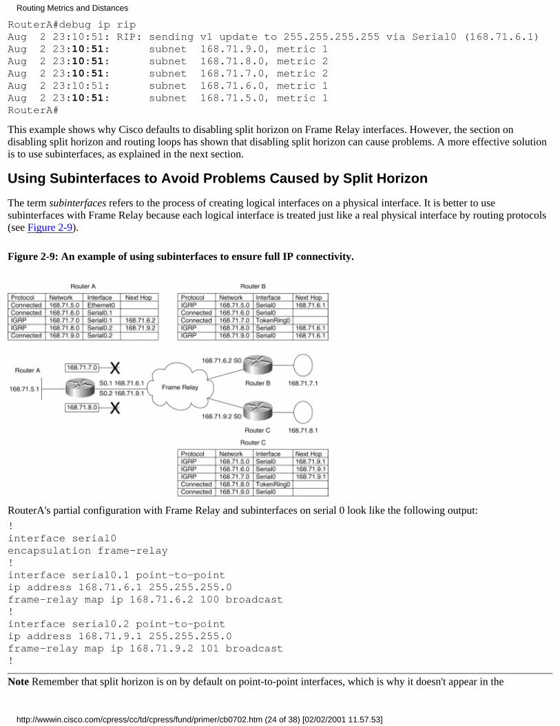
RouterA#debug ip ripAug 2 23:10:51: RIP: sending v1 update to 255.255.255.255 via Serial0 (168.71.6.1)Aug 2 23:10:51: subnet 168.71.9.0, metric 1Aug 2 23:10:51: subnet 168.71.8.0, metric 2Aug 2 23:10:51: subnet 168.71.7.0, metric 2Aug 2 23:10:51: subnet 168.71.6.0, metric 1Aug 2 23:10:51: subnet 168.71.5.0, metric 1RouterA#
This example shows why Cisco defaults to disabling split horizon on Frame Relay interfaces. However, the section ondisabling split horizon and routing loops has shown that disabling split horizon can cause problems. A more effective solutionis to use subinterfaces, as explained in the next section.
Using Subinterfaces to Avoid Problems Caused by Split Horizon
The term subinterfaces refers to the process of creating logical interfaces on a physical interface. It is better to usesubinterfaces with Frame Relay because each logical interface is treated just like a real physical interface by routing protocols(see Figure 2-9).
Figure 2-9: An example of using subinterfaces to ensure full IP connectivity.
RouterA's partial configuration with Frame Relay and subinterfaces on serial 0 look like the following output:
!interface serial0encapsulation frame-relay!interface serial0.1 point-to-pointip address 168.71.6.1 255.255.255.0frame-relay map ip 168.71.6.2 100 broadcast!interface serial0.2 point-to-pointip address 168.71.9.1 255.255.255.0frame-relay map ip 168.71.9.2 101 broadcast!
Note Remember that split horizon is on by default on point-to-point interfaces, which is why it doesn't appear in the
Routing Metrics and Distances
http://wwwin.cisco.com/cpress/cc/td/cpress/fund/primer/cb0702.htm (24 of 38) [02/02/2001 11.57.53]

configuration.
Using subinterfaces allows RouterB and RouterC to have full connectivity even though RouterA is running split horizon onsubinterfaces 0.1 and 0.2.
The following debug ip rip messages from RouterA show that RouterA will now send advertisements to RouterB and RouterCthat allow them to create a complete routing table.
RouterA#debug ip ripAug 3 03:07:01: RIP: sending v1 update to 255.255.255.255 via Serial0.1 (168.71.6.1)Aug 3 03:07:01: subnet 168.71.9.0, metric 1Aug 3 03:07:01: subnet 168.71.8.0, metric 2Aug 3 03:07:01: subnet 168.71.5.0, metric 1Aug 3 03:07:01: RIP: sending v1 update to 255.255.255.255 via Serial0.2 (168.71.9.1)Aug 3 03:07:01: subnet 168.71.7.0, metric 2Aug 3 03:07:01: subnet 168.71.6.0, metric 1Aug 3 03:07:01: subnet 168.71.5.0, metric 1RouterA#
Poison Reverse and Triggered UpdatesPoison reverse is when a router informs other routers that routes they were once capable of reaching via a particular interfaceare no longer reachable because the interface has gone down.
Routers normally react to a poison reverse message by immediately placing the poisoned routes into holddown instead ofwaiting for the invalid timer to expire. This saves convergence time, as much as 180 seconds (default invalid timer), dependingon how soon after a regular update a poison reverse update arrives.
In Figure 2-10, RouterA's serial 1 interface is shut down. RouterA can no longer reach 168.71.9.0 and 168.71.8.0 out of serial1.
Figure 2-10: Serial 1 on RouterA has been shut down.
By poisoning the routes out serial 0, RouterA is informing any other routers downstream from serial 0 that it can no longerreach these two subnets. This is, in essence, what a poison advertisement is.
When it receives these poison advertisements, RouterB deletes its references to the two subnets and puts them in holddown.This saves RouterB from having to wait until the invalid timers fire for these subnets to go into holddown.
The debug messages in this scenario have been edited to only show activities related to subnets 168.71.8.0 and 168.71.9.0.Here, you can see the output of debug ip rip from RouterA when serial 1 is shut down. The shutdown command is shown onthe line separating the two sections of the debug message.
RouterA#debug ip ripRouterA#config termRouterA-config#interface serial 1RouterA#-config-if#Oct 3 17:02:25: RIP: sending v1 update to 255.255.255.255 via Serial0 (168.71.6.1)Oct 3 17:02:25: subnet 168.71.9.0, metric 1
Routing Metrics and Distances
http://wwwin.cisco.com/cpress/cc/td/cpress/fund/primer/cb0702.htm (25 of 38) [02/02/2001 11.57.53]
Oct 3 17:02:25: subnet 168.71.8.0, metric 2RouterA-config-if#shutdownOct 3 17:02:33: RIP: sending v1 update to 255.255.255.255 via Serial0 (168.71.6.1)Oct 3 17:02:33: subnet 168.71.9.0, metric 16Oct 3 17:02:33: subnet 168.71.8.0, metric 16RouterA#
RouterA sent an update to RouterB just before the shutdown command was entered. Entering the shutdown commandautomatically triggered another update that poisoned the two routes. This process is sometimes referred to as a triggeredupdate, meaning that an exception event occurred that required an out-of-cycle update to be sent. You can see that the poisonupdate was out of cycle because only eight seconds separate the two messages. RIP's default update timer is 30 seconds. Thisexample is yet another way router code can be written to speed convergence.
The following code shows the output of debug ip rip from RouterB's point of view. Notice that RouterB immediately reacts toRouterA's poisoning of the routes to both subnets by placing them in hold down.
RouterB#debug ip ripOct 3 17:02:31: RIP: received update from 168.71.6.1 on Serial0Oct 3 17:02:31: 168.71.9.0 in 1 hopsOct 3 17:02:31: 168.71.8.0 in 2 hopsOct 3 17:02:40: RIP: received update from 168.71.6.1 on Serial0Oct 3 17:02:40: 168.71.9.0 in 16 hops (inaccessible)Oct 3 17:02:40: 168.71.8.0 in 16 hops (inaccessible)
This section covers a very important point. By using poison reverse and triggered updates instead of waiting for the entire180-second invalid timer to expire, routers can learn much more quickly that a route may not be reachable via the pathcurrently in their routing tables. Obtaining this information immediately rather than waiting for a series of scheduled updates tonot arrive allows a router to place the lost routes into hold down much faster.
IGRP Routing Metrics (Variables) and Cisco AdministrativeDistancesThis section covers two of the five possible variables of IGRP (Interior Gateway Routing Protocol) routing metrics---bandwidth and delay. It explains why only two are used and why it is usually best to accept the defaults for these two variablesbased on the type of link in use and its speed. It also discusses the concept of administrative distances.
IGRP Metrics (Variables)
IGRP can be configured to take the following variables into account when determining which routes to use:
Bandwidth: This is a measure of the speed of the physical network connected to an interface. A 64K serial connectionhas a bandwidth of 64,000 bits per second. Cisco uses a factor of 1000 in the bandwidth command. Therefore, enteringthe command bandwidth 64 on a serial interface results in a configured bandwidth of 64K.
●
Delay: This is an arbitrary measurement of how long it takes an interface to serialize the maximum size of a packet thatan interface can accept onto the physical media. Slower links have higher delays, and faster links have lower delays. Thenumber used on the interface is not determined dynamically; it is configured to a static value by a network administratoror left at the Cisco default.
●
Load: In Cisco terms, this is a measurement that is taken over a period of time and averaged. It doesn't reflect an exactinstant in time but is meant to reflect the utilization of a link.
●
Reliability: In Cisco terms, this is a measurement that is taken over a period of time and averaged. It doesn't reflect anexact instant in time but is meant to reflect the condition of a link. It can incorporate how often the link transitions froman up state to a down state, as well as the error rate of frames arriving on the link.
●
MTU (maximum transmission unit): This represents the largest frame a link can accept.●
Cisco recommends that only bandwidth and delay be used due to the following factors:
Routing Metrics and Distances
http://wwwin.cisco.com/cpress/cc/td/cpress/fund/primer/cb0702.htm (26 of 38) [02/02/2001 11.57.53]
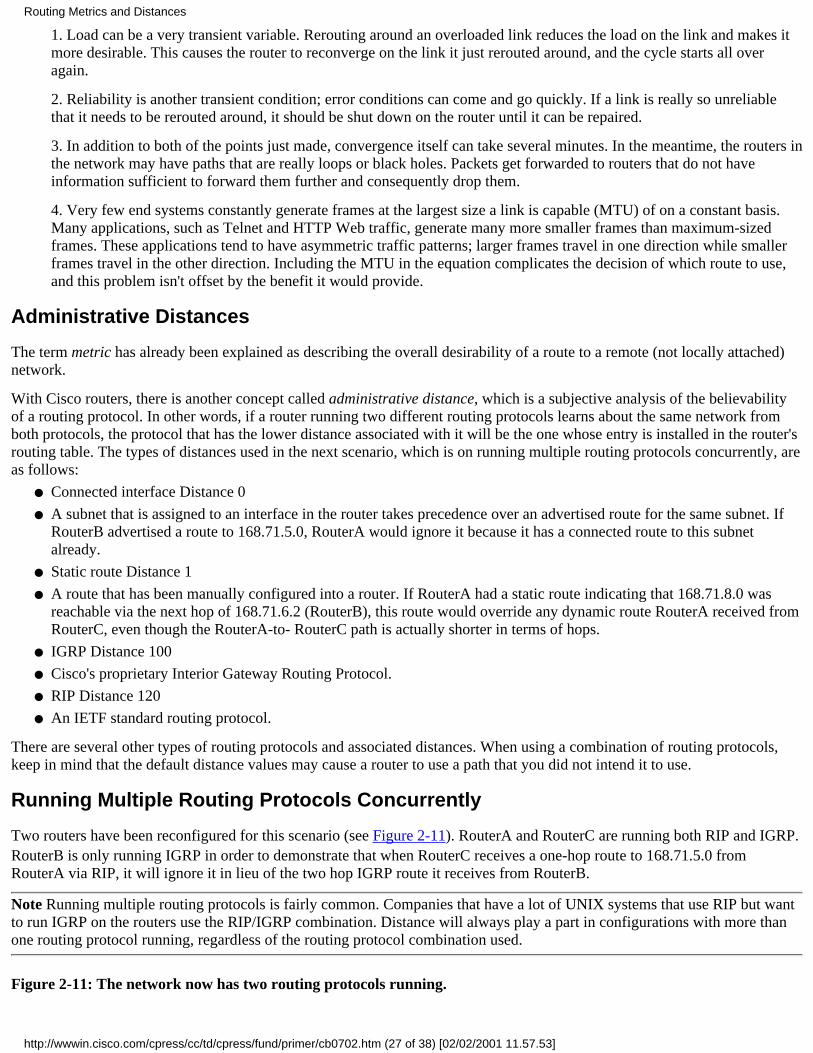
1. Load can be a very transient variable. Rerouting around an overloaded link reduces the load on the link and makes itmore desirable. This causes the router to reconverge on the link it just rerouted around, and the cycle starts all overagain.
2. Reliability is another transient condition; error conditions can come and go quickly. If a link is really so unreliablethat it needs to be rerouted around, it should be shut down on the router until it can be repaired.
3. In addition to both of the points just made, convergence itself can take several minutes. In the meantime, the routers inthe network may have paths that are really loops or black holes. Packets get forwarded to routers that do not haveinformation sufficient to forward them further and consequently drop them.
4. Very few end systems constantly generate frames at the largest size a link is capable (MTU) of on a constant basis.Many applications, such as Telnet and HTTP Web traffic, generate many more smaller frames than maximum-sizedframes. These applications tend to have asymmetric traffic patterns; larger frames travel in one direction while smallerframes travel in the other direction. Including the MTU in the equation complicates the decision of which route to use,and this problem isn't offset by the benefit it would provide.
Administrative Distances
The term metric has already been explained as describing the overall desirability of a route to a remote (not locally attached)network.
With Cisco routers, there is another concept called administrative distance, which is a subjective analysis of the believabilityof a routing protocol. In other words, if a router running two different routing protocols learns about the same network fromboth protocols, the protocol that has the lower distance associated with it will be the one whose entry is installed in the router'srouting table. The types of distances used in the next scenario, which is on running multiple routing protocols concurrently, areas follows:
Connected interface Distance 0●
A subnet that is assigned to an interface in the router takes precedence over an advertised route for the same subnet. IfRouterB advertised a route to 168.71.5.0, RouterA would ignore it because it has a connected route to this subnetalready.
●
Static route Distance 1●
A route that has been manually configured into a router. If RouterA had a static route indicating that 168.71.8.0 wasreachable via the next hop of 168.71.6.2 (RouterB), this route would override any dynamic route RouterA received fromRouterC, even though the RouterA-to- RouterC path is actually shorter in terms of hops.
●
IGRP Distance 100●
Cisco's proprietary Interior Gateway Routing Protocol.●
RIP Distance 120●
An IETF standard routing protocol.●
There are several other types of routing protocols and associated distances. When using a combination of routing protocols,keep in mind that the default distance values may cause a router to use a path that you did not intend it to use.
Running Multiple Routing Protocols Concurrently
Two routers have been reconfigured for this scenario (see Figure 2-11). RouterA and RouterC are running both RIP and IGRP.RouterB is only running IGRP in order to demonstrate that when RouterC receives a one-hop route to 168.71.5.0 fromRouterA via RIP, it will ignore it in lieu of the two hop IGRP route it receives from RouterB.
Note Running multiple routing protocols is fairly common. Companies that have a lot of UNIX systems that use RIP but wantto run IGRP on the routers use the RIP/IGRP combination. Distance will always play a part in configurations with more thanone routing protocol running, regardless of the routing protocol combination used.
Figure 2-11: The network now has two routing protocols running.
Routing Metrics and Distances
http://wwwin.cisco.com/cpress/cc/td/cpress/fund/primer/cb0702.htm (27 of 38) [02/02/2001 11.57.53]
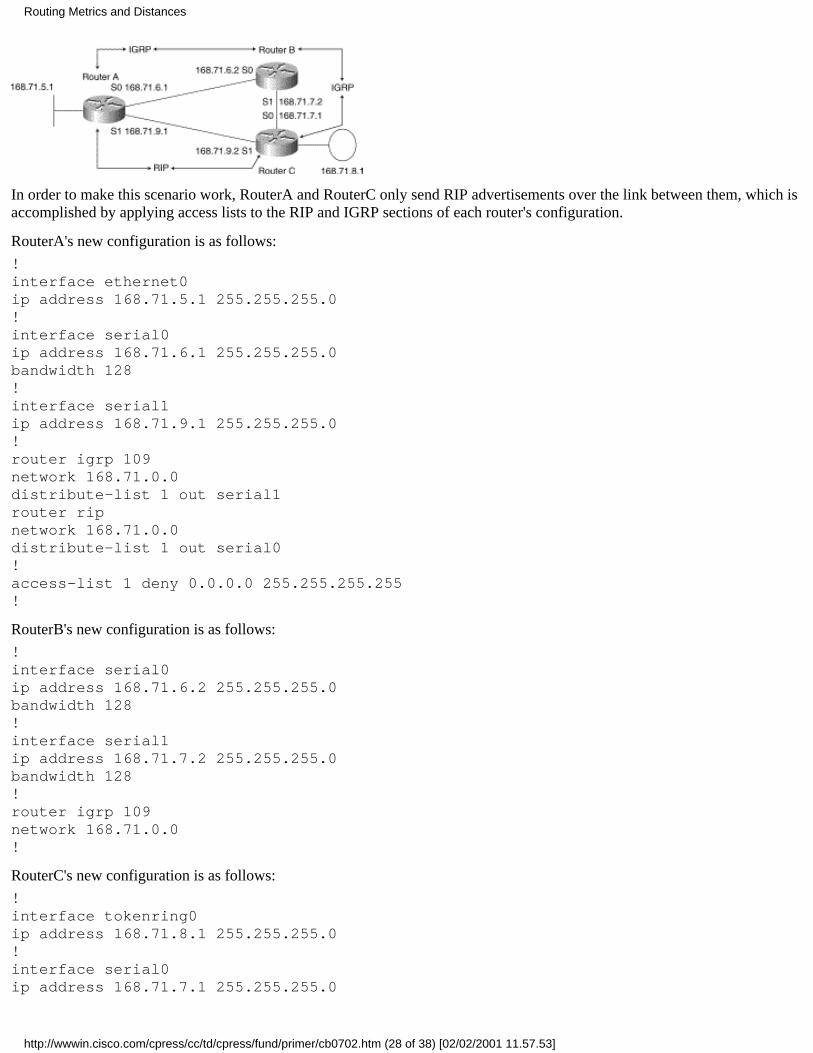
In order to make this scenario work, RouterA and RouterC only send RIP advertisements over the link between them, which isaccomplished by applying access lists to the RIP and IGRP sections of each router's configuration.
RouterA's new configuration is as follows:
!interface ethernet0ip address 168.71.5.1 255.255.255.0!interface serial0ip address 168.71.6.1 255.255.255.0bandwidth 128!interface serial1ip address 168.71.9.1 255.255.255.0!router igrp 109network 168.71.0.0distribute-list 1 out serial1router ripnetwork 168.71.0.0distribute-list 1 out serial0!access-list 1 deny 0.0.0.0 255.255.255.255!
RouterB's new configuration is as follows:
!interface serial0ip address 168.71.6.2 255.255.255.0bandwidth 128!interface serial1ip address 168.71.7.2 255.255.255.0bandwidth 128!router igrp 109network 168.71.0.0!
RouterC's new configuration is as follows:
!interface tokenring0ip address 168.71.8.1 255.255.255.0!interface serial0ip address 168.71.7.1 255.255.255.0
Routing Metrics and Distances
http://wwwin.cisco.com/cpress/cc/td/cpress/fund/primer/cb0702.htm (28 of 38) [02/02/2001 11.57.53]

bandwidth 128!interface serial1ip address 168.71.9.2 255.255.255.0!router igrp 109network 168.71.0.0distribute-list 1 out serial1router ripnetwork 168.71.0.0distribute-list 1 out serial0!access-list 1 deny 0.0.0.0 255.255.255.255!
In the following output from the debug ip rip and debug ip igrp transactions commands, you can see the debug messages fromboth routing protocols as they arrive at RouterC.
RouterC#debug ip ripOct 7 22:33:10: RIP: received update from 168.71.9.1 on Serial1Oct 7 22:33:10: 168.71.6.0 in 1 hopsOct 7 22:33:10: 168.71.5.0 in 1 hopsRouterC#deb ip igrp transactionsOct 7 22:35:59: IGRP: received update from 168.71.7.2 on Serial0Oct 7 22:35:59: subnet 168.71.6.0, metric 82125 (neighbor 80125)Oct 7 22:35:59: subnet 168.71.5.0, metric 10004001 (neighbor 10002001)
Note The debug ip rip and the debug ip igrp transactions commands perform the same function for their respective routingprotocols. See the Cisco IOS documentation for more details on these two commands.
Notice in the following routing table from RouterC that the route to 168.71.5.0 is via serial 0 through RouterB even though theconnection via serial 1 is only one hop. This is because, as previously explained, IGRP has a distance of 100, whereas RIP hasa distance of 120. The smaller distance value overrides what appears to be a physically shorter route.
RouterC#show ip routeCodes: C - connected, S - static, I - IGRP, R - RIP, M - mobile, B - BGP D - EIGRP, EX - EIGRP external, O - OSPF, IA - OSPF inter area E1 - OSPF external type 1, E2 - OSPF external type 2, E - EGP i - IS-IS, L1 - IS-IS level-1, L2 - IS-IS level-2, * - candidate defaultGateway of last resort is 168.71.7.2 to network 10.0.0.0I* 10.0.0.0 [100/180250] via 168.71.7.2, 00:00:47, Serial0168.71.0.0 255.255.255.0 is subnetted, 5 subnetsC 168.71.9.0 is directly connected, Serial1C 168.71.8.0 is directly connected, TokenRing0C 168.71.7.0 is directly connected, Serial0I 168.71.6.0 [100/82125] via 168.71.7.2, 00:00:47, Serial0I 168.71.5.0 [100/10004001] via 168.71.7.2, 00:00:47, Serial0R* 0.0.0.0 0.0.0.0 [120/1] via 168.71.9.1, 00:00:18, Serial1RouterC#
If the links connecting RouterA to RouterB and RouterB to RouterC were both T1s (1.54MB), and the link between RouterAand RouterC were 256K (a fractional T1), the best path from a bandwidth perspective would be the one that IGRP selected inthis instance. RIP lacks the capability to take into account the speed of the links it is being used over. If all of the routers inFigure 2-11 were running IGRP, the path from RouterA to 168.71.8.0 would be via RouterB.
Routing Metrics and Distances
http://wwwin.cisco.com/cpress/cc/td/cpress/fund/primer/cb0702.htm (29 of 38) [02/02/2001 11.57.53]
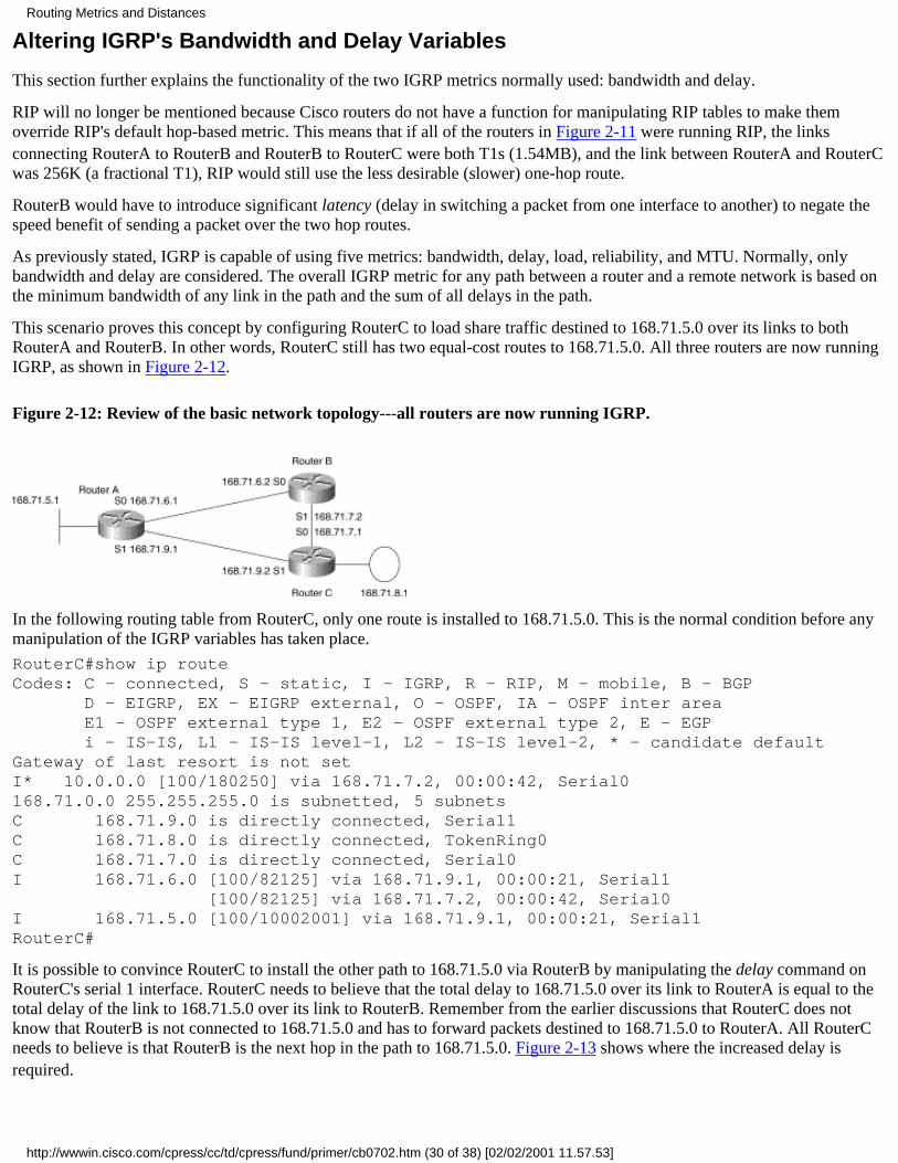
Altering IGRP's Bandwidth and Delay Variables
This section further explains the functionality of the two IGRP metrics normally used: bandwidth and delay.
RIP will no longer be mentioned because Cisco routers do not have a function for manipulating RIP tables to make themoverride RIP's default hop-based metric. This means that if all of the routers in Figure 2-11 were running RIP, the linksconnecting RouterA to RouterB and RouterB to RouterC were both T1s (1.54MB), and the link between RouterA and RouterCwas 256K (a fractional T1), RIP would still use the less desirable (slower) one-hop route.
RouterB would have to introduce significant latency (delay in switching a packet from one interface to another) to negate thespeed benefit of sending a packet over the two hop routes.
As previously stated, IGRP is capable of using five metrics: bandwidth, delay, load, reliability, and MTU. Normally, onlybandwidth and delay are considered. The overall IGRP metric for any path between a router and a remote network is based onthe minimum bandwidth of any link in the path and the sum of all delays in the path.
This scenario proves this concept by configuring RouterC to load share traffic destined to 168.71.5.0 over its links to bothRouterA and RouterB. In other words, RouterC still has two equal-cost routes to 168.71.5.0. All three routers are now runningIGRP, as shown in Figure 2-12.
Figure 2-12: Review of the basic network topology---all routers are now running IGRP.
In the following routing table from RouterC, only one route is installed to 168.71.5.0. This is the normal condition before anymanipulation of the IGRP variables has taken place.
RouterC#show ip routeCodes: C - connected, S - static, I - IGRP, R - RIP, M - mobile, B - BGP D - EIGRP, EX - EIGRP external, O - OSPF, IA - OSPF inter area E1 - OSPF external type 1, E2 - OSPF external type 2, E - EGP i - IS-IS, L1 - IS-IS level-1, L2 - IS-IS level-2, * - candidate defaultGateway of last resort is not setI* 10.0.0.0 [100/180250] via 168.71.7.2, 00:00:42, Serial0 168.71.0.0 255.255.255.0 is subnetted, 5 subnetsC 168.71.9.0 is directly connected, Serial1C 168.71.8.0 is directly connected, TokenRing0C 168.71.7.0 is directly connected, Serial0I 168.71.6.0 [100/82125] via 168.71.9.1, 00:00:21, Serial1 [100/82125] via 168.71.7.2, 00:00:42, Serial0I 168.71.5.0 [100/10002001] via 168.71.9.1, 00:00:21, Serial1RouterC#
It is possible to convince RouterC to install the other path to 168.71.5.0 via RouterB by manipulating the delay command onRouterC's serial 1 interface. RouterC needs to believe that the total delay to 168.71.5.0 over its link to RouterA is equal to thetotal delay of the link to 168.71.5.0 over its link to RouterB. Remember from the earlier discussions that RouterC does notknow that RouterB is not connected to 168.71.5.0 and has to forward packets destined to 168.71.5.0 to RouterA. All RouterCneeds to believe is that RouterB is the next hop in the path to 168.71.5.0. Figure 2-13 shows where the increased delay isrequired.
Routing Metrics and Distances
http://wwwin.cisco.com/cpress/cc/td/cpress/fund/primer/cb0702.htm (30 of 38) [02/02/2001 11.57.53]
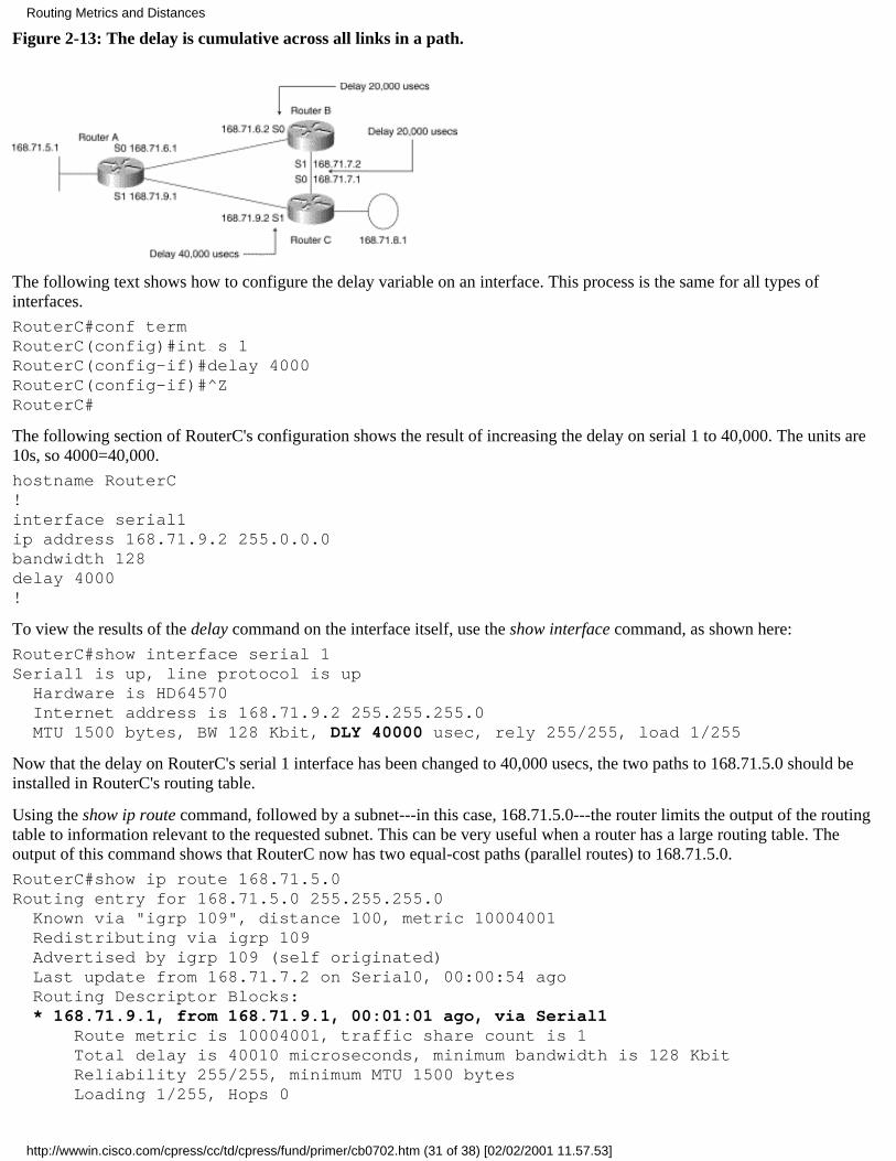
Figure 2-13: The delay is cumulative across all links in a path.
The following text shows how to configure the delay variable on an interface. This process is the same for all types ofinterfaces.
RouterC#conf termRouterC(config)#int s 1RouterC(config-if)#delay 4000RouterC(config-if)#^ZRouterC#
The following section of RouterC's configuration shows the result of increasing the delay on serial 1 to 40,000. The units are10s, so 4000=40,000.
hostname RouterC!interface serial1ip address 168.71.9.2 255.0.0.0bandwidth 128delay 4000!
To view the results of the delay command on the interface itself, use the show interface command, as shown here:
RouterC#show interface serial 1Serial1 is up, line protocol is up Hardware is HD64570 Internet address is 168.71.9.2 255.255.255.0 MTU 1500 bytes, BW 128 Kbit, DLY 40000 usec, rely 255/255, load 1/255
Now that the delay on RouterC's serial 1 interface has been changed to 40,000 usecs, the two paths to 168.71.5.0 should beinstalled in RouterC's routing table.
Using the show ip route command, followed by a subnet---in this case, 168.71.5.0---the router limits the output of the routingtable to information relevant to the requested subnet. This can be very useful when a router has a large routing table. Theoutput of this command shows that RouterC now has two equal-cost paths (parallel routes) to 168.71.5.0.
RouterC#show ip route 168.71.5.0Routing entry for 168.71.5.0 255.255.255.0 Known via "igrp 109", distance 100, metric 10004001 Redistributing via igrp 109 Advertised by igrp 109 (self originated) Last update from 168.71.7.2 on Serial0, 00:00:54 ago Routing Descriptor Blocks: * 168.71.9.1, from 168.71.9.1, 00:01:01 ago, via Serial1 Route metric is 10004001, traffic share count is 1 Total delay is 40010 microseconds, minimum bandwidth is 128 Kbit Reliability 255/255, minimum MTU 1500 bytes Loading 1/255, Hops 0
Routing Metrics and Distances
http://wwwin.cisco.com/cpress/cc/td/cpress/fund/primer/cb0702.htm (31 of 38) [02/02/2001 11.57.53]

168.71.7.2, from 168.71.7.2, 00:00:54 ago, via Serial0 Route metric is 10004001, traffic share count is 1 Total delay is 40010 microseconds, minimum bandwidth is 128 Kbit Reliability 255/255, minimum MTU 1500 bytes Loading 1/255, Hops 1RouterC#
The following output of debug ip igrp transactions from RouterC shows both routes to 168.71.5.0 being advertised to RouterCwith the same metric. The first message is from RouterA; the second is from RouterB. This is why the previous routing tablehas both routes in it.
RouterC#debug ip igrp transactionsOct 8 16:57:59: IGRP: received update from 168.71.9.1 on Serial1Oct 8 16:57:59: subnet 168.71.6.0, metric 84125 (neighbor 80125)Oct 8 16:57:59: subnet 168.71.5.0, metric 10004001 (neighbor 10000001)Oct 8 16:58:24: IGRP: received update from 168.71.7.2 on Serial0Oct 8 16:58:24: subnet 168.71.9.0, metric 84125 (neighbor 82125)Oct 8 16:58:24: subnet 168.71.6.0, metric 82125 (neighbor 80125)Oct 8 16:58:24: subnet 168.71.5.0, metric 10004001 (neighbor 10002001)RouterC#
Note A key point to understand is that a router uses the delay on an interface it receives a routing advertisement over todetermine the metrics for the routes being advertised. In other words, delay is applied on inbound advertisements, notoutbound. The delay variable was not changed on RouterA. Instead, it was changed on RouterC in order to force RouterC toaccept RouterA's advertisement for 168.71.5.0.
RouterC now load balances over the two links in either a session-by-session basis or a packet-by-packet basis. This may resultin better utilization of the links between RouterC and RouterA. However, if RouterB is already sending enough traffic toRouterA to keep the link nearly full, the extra traffic from RouterC may cause it to be oversubscribed. Care should always beused when manipulating routing tables to make them behave in a way that is different from their default behavior. The endresults may not be what you expected.
Problems with Manipulating the Delay Variable
It is not possible to have both RouterB and RouterC load balance their traffic to 168.71.5.0. Figure 2-14 shows where theincreased delay is required for RouterB to load balance.
Figure 2-14: The delay is still cumulative across all links in a path, which prevents load balancing.
In order for RouterB to accept RouterC's and RouterA's advertisements for 168.71.5.0, the total delay on both paths fromRouterB's perspective have to be equal. Because the delay on RouterC's serial 1 interface was changed to 40,000 usecs to forceRouterC to load share, RouterB's serial 0 interface delay would have to be changed to 60,000 usecs---20,000 for the link toRouterC and an additional 40,000 for the link between RouterC and RouterA. This would affect the total delay that RouterC'spath to 168.71.5.0 via RouterB encounters. RouterC would now have a path to 168.71.5.0 via RouterA with a delay of 40,000usecs and a path to 168.71.5.0 via RouterB with a total delay of 80,000 usecs---20,000 for the link to RouterB and the
Routing Metrics and Distances
http://wwwin.cisco.com/cpress/cc/td/cpress/fund/primer/cb0702.htm (32 of 38) [02/02/2001 11.57.53]

additional 60,000 for RouterB's link to RouterA.
The next section illustrates what happens to the metrics advertised with routes when the delay variable is altered.
Understanding the Effects of Manipulating the Delay Variable
Increasing the delay on an interface causes the router to alter the metric it uses to advertise routes learned over the link to otherrouters. The delay on RouterB's serial 0 interface was changed to 40,000 usecs, which will cause RouterB to alter the metrics ituses for routes learned from RouterA when advertising them to RouterC. Figure 2-15 shows where the increased delay isapplied.
Figure 2-15: The delay parameter has been increased as shown.
The following output of the show interface command on RouterB shows that the delay on its serial 0 has been increased to40,000:
RouterB#show interface serial 0Serial0 is up, line protocol is up Hardware is HD64570 Internet address is 168.71.6.2 255.255.255.0 MTU 1500 bytes, BW 128 Kbit, DLY 40000 usec, rely 255/255, load 1/255
The following code is RouterC's entry for 168.71.5.0 now that RouterB has had the delay on serial 0 increased to 40,000 usecs.Note that the metric for this route is the same as before for serial 1: 10004001. The other route via serial 0 is not installedbecause the metric has increased from RouterB. The combined delay that RouterC sees for the path to 168.71.5.0 via RouterBis now 60,000 usecs---20,000 usecs for the link to RouterB and 40,000 usecs for the link between RouterB and RouterA.
The following output of debug ip igrp transactions from RouterC shows the advertisements for 168.71.5.0 arriving fromRouterA and RouterB with different metrics. The first message is from RouterA and the second is from RouterB.
RouterC#debug ip igrp transactionsOct 8 16:55:09: IGRP: received update from 168.71.9.1 on Serial1Oct 8 16:55:09: subnet 168.71.6.0, metric 84125 (neighbor 80125)Oct 8 16:55:09: subnet 168.71.5.0, metric 10004001 (neighbor 10000001)Oct 8 16:55:29: IGRP: received update from 168.71.7.2 on Serial0Oct 8 16:55:29: subnet 168.71.6.0, metric 84125 (neighbor 82125)Oct 8 16:55:29: subnet 168.71.5.0, metric 10006001 (neighbor 10004001)
The difference in the metrics is why the routing table from RouterC has only one route to 168.71.5.0 in it.
RouterC#show ip route 168.71.5.0Routing entry for 168.71.5.0 255.255.255.0 Known via "igrp 109", distance 100, metric 10004001 Redistributing via igrp 109 Advertised by igrp 109 (self originated) Last update from 168.71.9.1 on Serial1, 00:00:20 ago Routing Descriptor Blocks: * 168.71.9.1, from 168.71.9.1, 00:00:20 ago, via Serial1
Routing Metrics and Distances
http://wwwin.cisco.com/cpress/cc/td/cpress/fund/primer/cb0702.htm (33 of 38) [02/02/2001 11.57.53]

Route metric is 10004001, traffic share count is 1 Total delay is 40010 microseconds, minimum bandwidth is 128 Kbit Reliability 255/255, minimum MTU 1500 bytes Loading 1/255, Hops 0RouterC#
Compare the previous routing table, which was observed after RouterB's delay on serial 0 was increased to 40,000 usecs asshown in Figure 2-15, with the routing table and debug messages observed while RouterB's delay on serial 0 was still 20,000usecs as shown in Figure 2-13:
RouterC#show ip route 168.71.5.0Routing entry for 168.71.5.0 255.255.255.0 Known via "igrp 109", distance 100, metric 10004001 Redistributing via igrp 109 Advertised by igrp 109 (self originated) Last update from 168.71.7.2 on Serial0, 00:00:54 ago Routing Descriptor Blocks: * 168.71.9.1, from 168.71.9.1, 00:01:01 ago, via Serial1 Route metric is 10004001, traffic share count is 1 Total delay is 40010 microseconds, minimum bandwidth is 128 Kbit Reliability 255/255, minimum MTU 1500 bytes Loading 1/255, Hops 0 168.71.7.2, from 168.71.7.2, 00:00:54 ago, via Serial0 Route metric is 10004001, traffic share count is 1 Total delay is 40010 microseconds, minimum bandwidth is 128 Kbit Reliability 255/255, minimum MTU 1500 bytes Loading 1/255, Hops 1RouterC#
The following output of debug ip igrp transactions from RouterC shows both routes to 168.71.5.0 being advertised to RouterCwith the same metric. The first message is from RouterA; the second is from RouterB, which is why the previous routing tablehas both routes in it.
RouterC#debug ip igrp transactionsOct 8 16:57:59: IGRP: received update from 168.71.9.1 on Serial1Oct 8 16:57:59: subnet 168.71.6.0, metric 84125 (neighbor 80125)Oct 8 16:57:59: subnet 168.71.5.0, metric 10004001 (neighbor 10000001)Oct 8 16:58:24: IGRP: received update from 168.71.7.2 on Serial0Oct 8 16:58:24: subnet 168.71.9.0, metric 84125 (neighbor 82125)Oct 8 16:58:24: subnet 168.71.6.0, metric 82125 (neighbor 80125)Oct 8 16:58:24: subnet 168.71.5.0, metric 10004001 (neighbor 10002001)RouterC#
This section has explained how manipulating the delay variable affects routing metrics and some of its limitations. The nextsection explains the role of the bandwidth variable in more detail.
Understanding the Effects of Manipulating the Bandwidth Variable
This scenario illustrates that the bandwidth variable is not cumulative. Only the lowest bandwidth in a path is taken intoaccount when determining a metric for a route. This is illustrated by observing how changing the bandwidth on RouterB'sserial 0 interface affects the metric RouterB advertises to serial 0's subnet---168.71.6.0---but does not affect the metric RouterCuses for its route to 168.71.6.0.
Figure 2-16 shows that the bandwidth on RouterB's serial 0 interface has been changed to that of a T1 connection--- 1.54MB.
Figure 2-16: Changing the bandwidth on RouterB's serial 0 to a higher speed has no effect on RouterC.
Routing Metrics and Distances
http://wwwin.cisco.com/cpress/cc/td/cpress/fund/primer/cb0702.htm (34 of 38) [02/02/2001 11.57.53]
The following output from RouterB shows how to change the bandwidth variable and how to tell whether the change has takeneffect.
RouterB#config termRouterB(config)#interface serial 0RouterB(config-if)#bandwidth 1544RouterB(config-if)#^ZRouterB#show interface serial0Serial0 is up, line protocol is up Hardware is HD64570 Internet address is 168.71.6.2 255.255.255.0 MTU 1500 bytes, BW 1544 Kbit, DLY 20000 usec, rely 255/255, load 1/255
The following output of the debug ip igrp transactions command on RouterC shows the metric advertised by RouterB toRouterC for 168.71.6.0 before the bandwidth on RouterB's serial 0 was changed.
RouterC#debug ip igrp transactionsOct 8 16:58:24: IGRP: received update from 168.71.7.2 on Serial0Oct 8 16:58:24: subnet 168.71.6.0, metric 82125 (neighbor 80125)RouterC#
In the previous debug output from RouterC, the bandwidth was 128, as indicated in the show interface command on RouterBprovided here:
RouterB#show interface serial 0Serial0 is up, line protocol is up Hardware is HD64570 Internet address is 168.71.6.2 255.255.255.0 MTU 1500 bytes, BW 128 Kbit, DLY 20000 usec, rely 255/255, load 1/255
The following output of the debug ip igrp transactions command on RouterC, which was taken after changing the bandwidthon RouterB's serial 0, shows that the change affects the advertised metric that RouterC receives from RouterB for 168.71.6.0but does not affect the metric RouterC installs.
The installed metric is still 82125, even though the neighbor--- RouterB---indicated that its metric was 8476. This is becausethe bandwidth on RouterC's serial 0 interface remained the same: 64K.
RouterC#deb ip igrp transactionsOct 8 17:10:37: IGRP: received update from 168.71.7.2 on Serial0Oct 8 17:10:37: subnet 168.71.6.0, metric 82125 (neighbor 8476)RouterC#
In the previous debug output from RouterC, the bandwidth on RouterB's serial 0 interface was 1544, as indicated in the outputof the show interface command on RouterB provided here:
RouterB#show interface serial 0Serial0 is up, line protocol is up Hardware is HD64570 Internet address is 168.71.6.2 255.255.255.0 MTU 1500 bytes, BW 1544 Kbit, DLY 20000 usec, rely 255/255, load 1/255
Experimenting with the delay and bandwidth parameters in a small network, such as the one used in this example, will
Routing Metrics and Distances
http://wwwin.cisco.com/cpress/cc/td/cpress/fund/primer/cb0702.htm (35 of 38) [02/02/2001 11.57.53]
probably not create major problems. However, experimenting with bandwidth and delay in a 1,000-router network in anattempt to achieve load balancing on some paths will almost certainly lead to more problems than it solves.
Calculating IGRP Metrics
In this book, only two of the five IGRP metrics are considered, which is the default behavior. The other three variables are setto 1.
The following text from Cisco's technical tips section on Cisco Connection Online (CCO) www.cisco.com explains in detailthe formula for calculating IGRP metrics.
IGRP calculates the metric by adding together weighted values of different characteristics of the link to the network inquestion. These values (bandwidth, bandwidth divided by load, and delay) are weighted with the constants K1, K2, and K3.Here's the formula (BandW=bandwidth):
Metric = K1 * BandW + (K2 * BandW)/(256-load) + K3*Delay
The default constant values are K1=K3=1 and K2=K4=K5=0, so: Metric = BandW + Delay.
If K5 does not equal 0, an additional operation is done: Metric = Metric * [K5/(reliability + K4)]
To find BandW, find the smallest of all the bandwidths from outgoing interfaces and divide 10,000,000 by that number. (Thebandwidth is scaled by 10,000,000 in kilobits per second.)
To find Delay, add all the delays from the outgoing interfaces and divide this number by 10. (The delay is in tens ofmicroseconds.)
When the bandwidth was 128 and the delay was 20,000 usecs on RouterB's serial 0 interface, RouterB's advertised metric forthe subnet assigned to serial 0 was 80125. This is shown by the [neighbor 80125] statement in bold taken from RouterC'sdebug messages. Following is RouterC receiving an update from RouterB:
RouterC#debug ip igrp transactionsOct 8 16:58:24: IGRP: received update from 168.71.7.2 on Serial0Oct 8 16:58:24: subnet 168.71.6.0, metric 82125 (neighbor 80125)RouterC#
The following output of the show interface command on RouterB shows that RouterB's serial 0 interface has the bandwidth setto 128K:
RouterB#show interface serial 0Serial0 is up, line protocol is up Hardware is HD64570 Internet address is 168.71.6.2 255.255.255.0 MTU 1500 bytes, BW 128 Kbit, DLY 20000 usec, rely 255/255, load 1/255
The formula for determining the metric RouterB will use when advertising its connected route to 168.71.6.0 is as follows:
Bandwidth = 10,000,000/128,000 or 78125Delay = 20,000/10 or 2000 = 80125
When the bandwidth was 1544 and the delay was 20,000 usecs on RouterB's serial 0 interface, RouterB's advertised metric forthe subnet assigned to serial 0 was 8476. This is shown by the [neighbor 8476] statement in bold taken from RouterC's debugmessages. Following is RouterC receiving an update from RouterB:
RouterC#deb ip igrp transactionsOct 8 17:10:37: IGRP: received update from 168.71.7.2 on Serial0Oct 8 17:10:37: subnet 168.71.6.0, metric 82125 (neighbor 8476)RouterC#
The following output of the show interface command on RouterB shows that RouterB's serial 0 interface has the bandwidth setto 1544K:
Routing Metrics and Distances
http://wwwin.cisco.com/cpress/cc/td/cpress/fund/primer/cb0702.htm (36 of 38) [02/02/2001 11.57.53]
RouterB#show interface serial 0Serial0 is up, line protocol is up Hardware is HD64570 Internet address is 168.71.6.2 255.255.255.0 MTU 1500 bytes, BW 1544 Kbit, DLY 20000 usec, rely 255/255, load 1/255
The formula for determining the metric RouterB will use when advertising its connected route to 168.71.6.0 is as follows:
Bandwidth = 10,000,000/1,544,000 or 6476Delay = 20,000/10 or 2000 = 8476
When the bandwidth was 128 and the delay was 20,000 usecs on RouterB's serial 0 interface, RouterC's installed metric for168.71.6.0 was 82125. This is shown by the [metric 82125] statement in bold taken from RouterC's debug messages.Following is RouterC receiving an update from RouterB:
RouterC#debug ip igrp transactionsOct 8 16:58:24: IGRP: received update from 168.71.7.2 on Serial0Oct 8 16:58:24: subnet 168.71.6.0, metric 82125 (neighbor 80125)RouterC#
The following output of the show interface command on RouterC shows that RouterC's serial 0 interface has the bandwidth setto 128K:
RouterC#show interface serial 0Serial0 is up, line protocol is up Hardware is HD64570 Internet address is 168.71.7.1 255.255.255.0 MTU 1500 bytes, BW 128 Kbit, DLY 20000 usec, rely 255/255, load 1/255
The formula for determining the metric RouterC will use for 168.71.6.0 is as follows:
Bandwidth = 10,000,000/128 or 78125Delay = 40,000/10 or 4000 = 82125
When the bandwidth was 1544 and the delay was 20,000 usecs on RouterB's serial 0 interface, RouterC's installed metric for168.71.6.0 was still 82125. This is shown by the [metric 82125] statement in bold taken from RouterC's debug messages. Thisis RouterC receiving an update from RouterB:
RouterC#deb ip igrp transactionsOct 8 17:10:37: IGRP: received update from 168.71.7.2 on Serial0Oct 8 17:10:37: subnet 168.71.6.0, metric 82125 (neighbor 8476)RouterC#
The following output of the show interface command on RouterC shows that RouterC's serial 0 interface has the bandwidth setto 128K:
RouterC#show interface serial 0Serial0 is up, line protocol is up Hardware is HD64570 Internet address is 168.71.7.1 255.255.255.0 MTU 1500 bytes, BW 128 Kbit, DLY 20000 usec, rely 255/255, load 1/255
The formula for determining the metric RouterC will use for 168.71.6.0 is the same because the lowest bandwidth in the path isstill 128K.
Bandwidth = 10,000,000/128 or 78125Delay = 40,000/10 or 4000 = 82125
Routing Metrics and Distances
http://wwwin.cisco.com/cpress/cc/td/cpress/fund/primer/cb0702.htm (37 of 38) [02/02/2001 11.57.53]
SummaryThis chapter is important to your overall understanding of routing metrics and distances. You need to understand the topicsdiscussed in this chapter to be able to progress from here. You learned about convergence, which is the process that routers gothrough when a route has become unavailable. The primary activities of convergence are update, invalid, holddown, and flush.You also learned about parallel paths, the effect of parallel paths on convergence, the effect of parallel paths on packetforwarding, and how to review parallel paths in a routing table. The difference between process switching and fast switchingwas also discussed.
This chapter has touched upon the role of split horizon, including what it means for routing advertisements with split horizonenabled and disabled. Finally, IGRP routing metrics (variables) and Cisco administrative distances were explained."Discontiguous Networks, Summarization, and Subnet 0," continues the discussion by delving deeper into these topics.
Posted: Wed Mar 3 10:00:05 PST 1999Copyright 1989-1999©Cisco Systems Inc.Copyright © 1997 Macmillan Publishing USA, a Simon & Schuster Company
Routing Metrics and Distances
http://wwwin.cisco.com/cpress/cc/td/cpress/fund/primer/cb0702.htm (38 of 38) [02/02/2001 11.57.53]

Table of Contents
Discontiguous Networks, Summarization, and Subnet 0
Introduction to TerminologyDiscontiguous Networks Using RIP and IGRP
Understanding How a Router Derives the Correct MasksUnderstanding Summarization (Summarized Routes)Understanding Subnet 0
Summarized Routes Versus Subnet 0
Summarization Caused by Discontiguous Networks in Action
RIP Cannot Reach Discontiguous Subnets
Discontiguous Networks, Subnet 0, and Summarization Using IGRPDiscontiguous Networks Using Two RoutersDiscontiguous Networks Using Three Routers
When Connectivity Is PossibleWhen Connectivity Is Not PossibleAlternating Paths for the First Ping
Using Other Routing Protocols
Using Aggregation as a ToolSummary
Discontiguous Networks, Summarization, andSubnet 0This chapter groups together several concepts that affect network connectivity directly by altering the content of routinginformation shared between routers. These effects may be useful or detrimental, depending on how they are applied. Theseconcepts are usually considered together in order to fully explain their interaction. This chapter covers discontiguous networks,subnet 0, and summarization, as the chapter title implies. "Using IP Unnumbered and VLSM," continues this discussion.
Note Only RIP V1 (version 1) and IGRP are mentioned in this chapter because RIP V1 and IGRP do not include the subnetmasks associated with the routes they advertise. The routers receiving routing advertisements are forced to derive the correctsubnet masks by using the mask on the interface that the route advertisements are received over (see Figure 3-1 ).
Note EIGRP, OSPF, and RIP V2 are not covered because they do advertise masks with their routing advertisements.
Figure 3-1: Advertisements don't include subnet masks; the receiving router must derive the mask.
Note Notice in Figure 3-1 that the major network address of the link between RouterA and RouterB has been changed. It is
Discontiguous Networks, Summarization, and Subnet 0
http://wwwin.cisco.com/cpress/cc/td/cpress/fund/primer/cb0703.htm (1 of 19) [02/02/2001 11.58.24]
now 168.72.0.0. The configuration commands and related show interface commands are given in the section "SummarizationCaused by Discontiguous Networks in Action" .
Introduction to TerminologyBefore proceeding any further in this chapter, it is important to lay the groundwork for the discussion by defining some terms,as follows:
A major net(work) refers to the network-only portion of an Internet address. In Figure 3-1 , the major net of subnet168.71.5.0 is 168.71.0.0 because Class B addresses use only the first two of the four bytes in an IP address to determinethe network address space. The other two bytes can be used for host addresses or a combination of subnets and hostaddresses. In other words, the term major net is used for the bytes of an address that are reserved for the networkportion, based on the class of address in use. The major net for address 10.9.0.0 is 10.0.0.0. The major net for address223.221.142.8 with a mask of 255.255.255.248 is 223.221.142.0.
●
In a discontiguous network, IP subnet addresses from a major network are applied to physical networks that areseparated by a network with a different major net. In Figure 3-1 , the link between RouterA and RouterB has beenconfigured with a different network address (168.72.0.0).
●
To summarize means to report only the major net portion of an address, even though there are subnets of the address inthe routing table. In Figure 3-1 , RouterB has a network with subnet 168.71.8.0 assigned. When RouterB is preparing arouting update to send out serial 0, it will notice that serial 0 is part of a different major net and send out only thesummarized (in this case, major net) portion of the address.
●
Aggregation is very similar to summarization. In fact, many people use the terms interchangeably. This book treats theterms as similar, but not identical, functions. In the context of this book, aggregation means reducing the number ofsubnets in a routing advertisement by advertising only the common portion of the subnet addresses that is required toprovide full IP connectivity. If RouterA were connected to subnets 168.71.1.16, 168.71.1.32, and 168.71.1.48, andRouterB were connected to subnets 168.71.2.16, 168.71.2.32, and 168.71.2.48, each router could aggregate itsconnected subnets to the third byte. Full connectivity would be possible if RouterA advertised only 168.71.1.0 andRouterB advertised only 168.71.2.0. For a more detailed explanation, see the section on aggregation later in this chapter.
●
A major net boundary is a router connected to two or more major nets. In Figure 3-1 , RouterA is connected to twomajor nets: 168.71.0.0 and 168.72.0.0. The routing update for 168.71.5.0 that would be advertised over serial 0 toRouterB is encountering a major net boundary---168.71.0.0 >> 168.72.0.0. RouterA will summarize the 168.71.5.0 routeto the major net of 168.71.0.0.
●
Now that you are familiar with the terms used in this chapter, you can move on to the heart of the matter---starting withdiscontiguous networks.
Discontiguous Networks Using RIP and IGRPIn Figure 3-2 , network 168.71.0.0 is no longer contiguous. It is separated by a serial link that has a different majornetwork---168.72.0.0. This will cause both routers to summarize their subnets of 168.71.0.0 when sending advertisements.Summarization is explained in more detail later in this chapter.
Figure 3-2: Simplified network using different major network addresses.
For RIP, this means that neither router can reach the other's subnet of 168.71.0.0. The section on RIP that follows demonstratesthis concept.
Note For IGRP, the answer should have been the same as for RIP---neither router should have been able to reach the other's
Discontiguous Networks, Summarization, and Subnet 0
http://wwwin.cisco.com/cpress/cc/td/cpress/fund/primer/cb0703.htm (2 of 19) [02/02/2001 11.58.24]

subnet of 168.71.0.0. However, while I was writing this book, an anomaly was discovered in IGRP that has since been fixed.This anomaly allowed IGRP to accept summarized routes for major networks when it should not have done so. The section onIGRP and discontiguous networks was left as originally written, with the anomaly still in effect.
Note The nature of the anomaly provides a great opportunity to discuss some interesting and fairly subtle IP connectivityproblems and the methodologies used to track them down. More information on the anomaly is provided at the end of theIGRP section.
Before proceeding any further on the effects of discontiguous networks, the following fundamental principles need to beintroduced:
Understanding how a router derives the correct masks●
Understanding summarization●
Understanding subnet 0●
Summarized routes versus subnet 0●
Summarization caused by discontiguous networks in action●
Understanding How a Router Derives the Correct Masks
Even when they are not dealing with discontiguous networks, routers running RIP V1 and IGRP must determine which masksto associate with the networks and subnetworks for which they receive route advertisements. When discontiguous networks areadded to the picture, this process takes on even more significance. The normal methods these two protocols use to derivemasks do not work properly with discontiguous networks. Later sections in this chapter explain these problems in more detail.
Routers receiving a RIP V1 or IGRP routing advertisement use two methods for deriving the correct mask to associate in theadvertisement, as follows:
1. Advertisements for subnets that are part of the same major network as the IP address of the interface they are receivedover will have the subnet mask of the receiving interface applied to them.
2. All other networks in the advertisement should be for major networks, not subnets. This is because the router sendingthe advertisement should have summarized the subnets down to the major network before sending the advertisement.Therefore, the masks for all other networks should be the default mask for the class of address received.
In Figure 3-3 , RouterA sends an advertisement for subnet 168.71.5.0 to RouterB as an example of what can go wrong when arouter advertises subnets over a major net boundary. RouterB sees that 168.71.5.0 is in a different major net than its IP addresson serial 0. RouterB knows that 168.71.5.0 is not a major net because it has bits set in the third byte (Class B address major netadvertisements should have bits set only in the first two bytes).
RouterB has a few choices: ignore the route advertisement; install it with a mask of 255.255.255.255, indicating that it is a hostroute (has a full mask); or try to guess what mask should be used.
Figure 3-3: Advertising a subnet by mistake.
Attempting to guess the correct mask is difficult due to the many possible ways a subnet advertisement can be masked. Maskambiguity is a situation in which a router can use many different masks on a subnet for which it receives an advertisement (seeFigure 3-4).
Figure 3-4: Many possible masks.
Discontiguous Networks, Summarization, and Subnet 0
http://wwwin.cisco.com/cpress/cc/td/cpress/fund/primer/cb0703.htm (3 of 19) [02/02/2001 11.58.24]
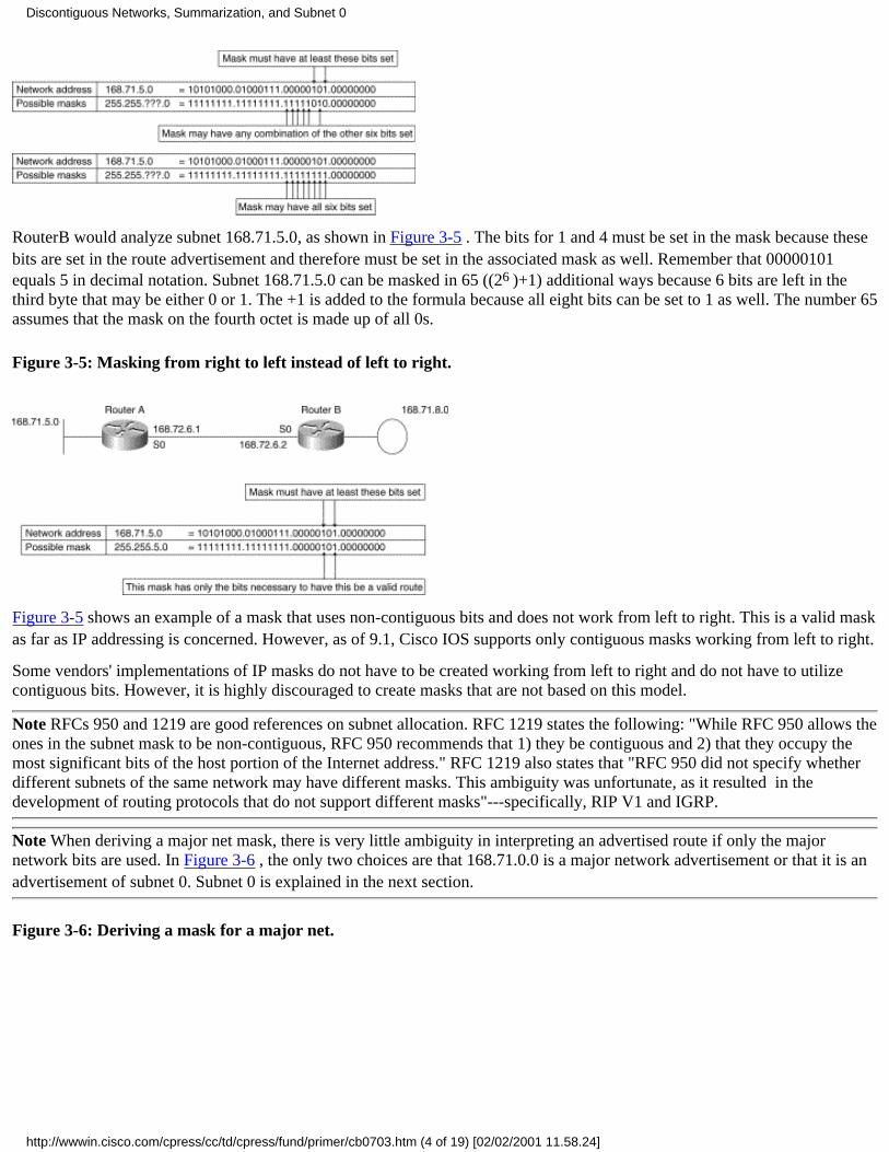
RouterB would analyze subnet 168.71.5.0, as shown in Figure 3-5 . The bits for 1 and 4 must be set in the mask because thesebits are set in the route advertisement and therefore must be set in the associated mask as well. Remember that 00000101equals 5 in decimal notation. Subnet 168.71.5.0 can be masked in 65 ((26 )+1) additional ways because 6 bits are left in thethird byte that may be either 0 or 1. The +1 is added to the formula because all eight bits can be set to 1 as well. The number 65assumes that the mask on the fourth octet is made up of all 0s.
Figure 3-5: Masking from right to left instead of left to right.
Figure 3-5 shows an example of a mask that uses non-contiguous bits and does not work from left to right. This is a valid maskas far as IP addressing is concerned. However, as of 9.1, Cisco IOS supports only contiguous masks working from left to right.
Some vendors' implementations of IP masks do not have to be created working from left to right and do not have to utilizecontiguous bits. However, it is highly discouraged to create masks that are not based on this model.
Note RFCs 950 and 1219 are good references on subnet allocation. RFC 1219 states the following: "While RFC 950 allows theones in the subnet mask to be non-contiguous, RFC 950 recommends that 1) they be contiguous and 2) that they occupy themost significant bits of the host portion of the Internet address." RFC 1219 also states that "RFC 950 did not specify whetherdifferent subnets of the same network may have different masks. This ambiguity was unfortunate, as it resulted in thedevelopment of routing protocols that do not support different masks"---specifically, RIP V1 and IGRP.
Note When deriving a major net mask, there is very little ambiguity in interpreting an advertised route if only the majornetwork bits are used. In Figure 3-6 , the only two choices are that 168.71.0.0 is a major network advertisement or that it is anadvertisement of subnet 0. Subnet 0 is explained in the next section.
Figure 3-6: Deriving a mask for a major net.
Discontiguous Networks, Summarization, and Subnet 0
http://wwwin.cisco.com/cpress/cc/td/cpress/fund/primer/cb0703.htm (4 of 19) [02/02/2001 11.58.24]
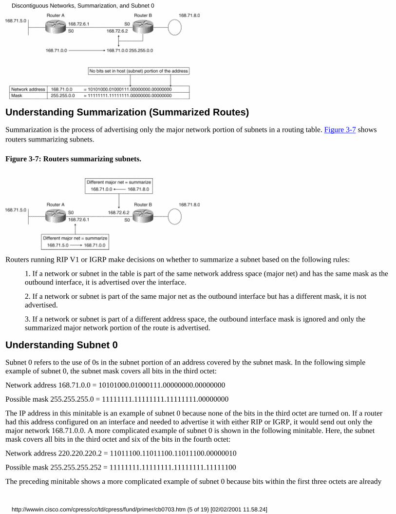
Understanding Summarization (Summarized Routes)
Summarization is the process of advertising only the major network portion of subnets in a routing table. Figure 3-7 showsrouters summarizing subnets.
Figure 3-7: Routers summarizing subnets.
Routers running RIP V1 or IGRP make decisions on whether to summarize a subnet based on the following rules:
1. If a network or subnet in the table is part of the same network address space (major net) and has the same mask as theoutbound interface, it is advertised over the interface.
2. If a network or subnet is part of the same major net as the outbound interface but has a different mask, it is notadvertised.
3. If a network or subnet is part of a different address space, the outbound interface mask is ignored and only thesummarized major network portion of the route is advertised.
Understanding Subnet 0
Subnet 0 refers to the use of 0s in the subnet portion of an address covered by the subnet mask. In the following simpleexample of subnet 0, the subnet mask covers all bits in the third octet:
Network address 168.71.0.0 = 10101000.01000111.00000000.00000000
Possible mask 255.255.255.0 = 11111111.11111111.11111111.00000000
The IP address in this minitable is an example of subnet 0 because none of the bits in the third octet are turned on. If a routerhad this address configured on an interface and needed to advertise it with either RIP or IGRP, it would send out only themajor network 168.71.0.0. A more complicated example of subnet 0 is shown in the following minitable. Here, the subnetmask covers all bits in the third octet and six of the bits in the fourth octet:
Network address 220.220.220.2 = 11011100.11011100.11011100.00000010
Possible mask 255.255.255.252 = 11111111.11111111.11111111.11111100
The preceding minitable shows a more complicated example of subnet 0 because bits within the first three octets are already
Discontiguous Networks, Summarization, and Subnet 0
http://wwwin.cisco.com/cpress/cc/td/cpress/fund/primer/cb0703.htm (5 of 19) [02/02/2001 11.58.24]

used as part of the Class C Internet address. This means that subnets must be created using only the fourth byte. In this case,subnet 0 means that none of the 6 bits in the fourth byte covered by the mask of 252 are set to 1.
If a router advertised this subnet using RIP V1 or IGRP, the advertisement would be 220.220.220.0---the same as for the majornet.
Summarized Routes Versus Subnet 0
Summarized routes look exactly like subnet 0 to routers running RIP V1 and IGRP. In Figure 3-8 and Table 3-1, you can seethat as far as RouterA is concerned, the two advertisements are identical. This is because, as previously mentioned, neither RIPV1 nor IGRP includes a mask with the routes it advertises
Figure 3-8: Sending a summarized route.
From a routing perspective, there is no difference between subnet 0 and the summarized route for 168.71.0.0, as shown inTable 3-1.
Table 3-1: Binary Example of Subnet 0 Versus a Summarized Route
Subnet 0Network address 168.71.0.0 = 10101000.01000111.00000000.00000000Subnet 0 mask 255.255.255.0 = 11111111.11111111.11111111.00000000Summarized RouteNetwork address 168.71.0.0 = 10101000.01000111.00000000.00000000Summarised mask 255.255.0.0 = 11111111.11111111.00000000.00000000
Summarization Caused by Discontiguous Networks in Action
This section provides real-life examples of summarization in action using RIP and IGRP.
Both routers have their configuration modified for the additional major network (see Figure 3-9 ). The show interfacecommands below the configuration commands show the new major net in place.
Figure 3-9: A reminder that a new major net has been configured on the serial link.
RouterA#conf tRouterA#-config#interface s0RouterA#-config-if# ip address 168.72.6.1 255.255.255.0RouterA#-config-if#^ZRouterA#RouterA#show interface serial 0
Discontiguous Networks, Summarization, and Subnet 0
http://wwwin.cisco.com/cpress/cc/td/cpress/fund/primer/cb0703.htm (6 of 19) [02/02/2001 11.58.24]

Serial0 is up, line protocol is up Hardware is HD64570 Internet address is 168.72.6.1 255.255.255.0 MTU 1500 bytes, BW 128 Kbit, DLY 20000 usec, rely 255/255, load 1/255RouterB#conf tRouterB#-config#interface s0RouterB#-config-if# ip address 168.72.6.2 255.255.255.0RouterB#-config-if#^ZRouterB#RouterB#show interface serial 0Serial0 is up, line protocol is up Hardware is HD64570 Internet address is 168.72.6.2 255.255.255.0 MTU 1500 bytes, BW 128 Kbit, DLY 20000 usec, rely 255/255, load 1/255
The portion of the configuration for adding 168.72.0.0 to the routing tables is the same for both routers. It is as follows:
!router ripnetwork 168.71.0.0network 168.72.0.0!
RIP Cannot Reach Discontiguous Subnets
Routers running RIP ignore summarized routes for networks to which they have connections, which is one reason why RIPdoesn't work with discontiguous networks (see Figure 3-10).
Figure 3-10: Summarized routes being advertised.
Recall that routers running RIP examine the network number and mask associated with an interface before advertising routesfrom the routing table over it. This was discussed previously in the section on understanding summarized routes.
In the following output of debug ip rip from RouterA, you can see RouterA sending and receiving advertisements for168.71.0.0 with a metric of 1:
RouterA#deb ip ripRIP: received update from 168.72.6.2 on Serial0 168.71.0.0 in 1 hopsRIP: sending update to 255.255.255.255 via Serial0 (168.72.6.1) network 168.71.0.0, metric 1
In the following routing table from RouterA, you can see that RouterA does not have a route installed to 168.71.0.0, eventhough RouterB is advertising it:
RouterA#show ip routeCodes: C - connected, S - static, I - IGRP, R - RIP, M - mobile, B - BGP D - EIGRP, EX - EIGRP external, O - OSPF, IA - OSPF inter area
Discontiguous Networks, Summarization, and Subnet 0
http://wwwin.cisco.com/cpress/cc/td/cpress/fund/primer/cb0703.htm (7 of 19) [02/02/2001 11.58.24]
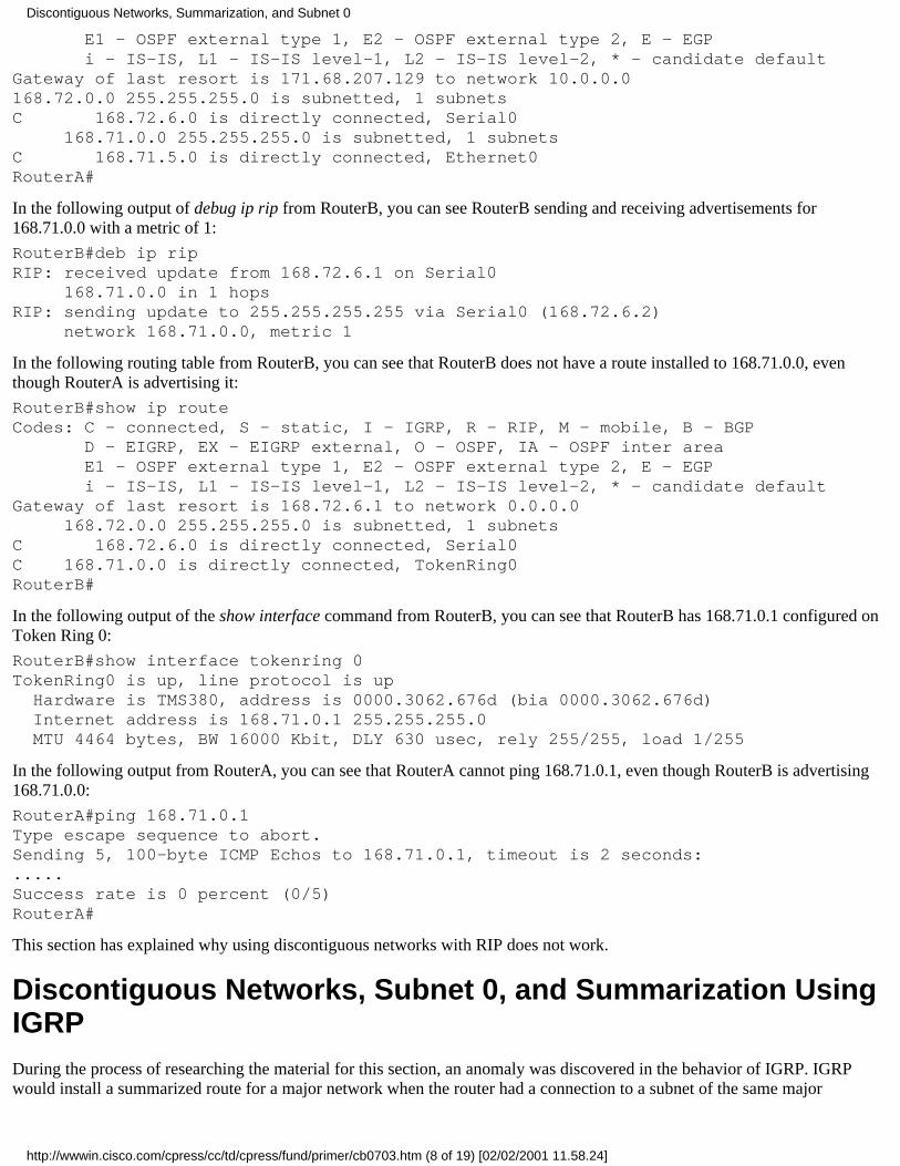
E1 - OSPF external type 1, E2 - OSPF external type 2, E - EGP i - IS-IS, L1 - IS-IS level-1, L2 - IS-IS level-2, * - candidate defaultGateway of last resort is 171.68.207.129 to network 10.0.0.0168.72.0.0 255.255.255.0 is subnetted, 1 subnetsC 168.72.6.0 is directly connected, Serial0 168.71.0.0 255.255.255.0 is subnetted, 1 subnetsC 168.71.5.0 is directly connected, Ethernet0RouterA#
In the following output of debug ip rip from RouterB, you can see RouterB sending and receiving advertisements for168.71.0.0 with a metric of 1:
RouterB#deb ip ripRIP: received update from 168.72.6.1 on Serial0 168.71.0.0 in 1 hopsRIP: sending update to 255.255.255.255 via Serial0 (168.72.6.2) network 168.71.0.0, metric 1
In the following routing table from RouterB, you can see that RouterB does not have a route installed to 168.71.0.0, eventhough RouterA is advertising it:
RouterB#show ip routeCodes: C - connected, S - static, I - IGRP, R - RIP, M - mobile, B - BGP D - EIGRP, EX - EIGRP external, O - OSPF, IA - OSPF inter area E1 - OSPF external type 1, E2 - OSPF external type 2, E - EGP i - IS-IS, L1 - IS-IS level-1, L2 - IS-IS level-2, * - candidate defaultGateway of last resort is 168.72.6.1 to network 0.0.0.0 168.72.0.0 255.255.255.0 is subnetted, 1 subnetsC 168.72.6.0 is directly connected, Serial0C 168.71.0.0 is directly connected, TokenRing0RouterB#
In the following output of the show interface command from RouterB, you can see that RouterB has 168.71.0.1 configured onToken Ring 0:
RouterB#show interface tokenring 0TokenRing0 is up, line protocol is up Hardware is TMS380, address is 0000.3062.676d (bia 0000.3062.676d) Internet address is 168.71.0.1 255.255.255.0 MTU 4464 bytes, BW 16000 Kbit, DLY 630 usec, rely 255/255, load 1/255
In the following output from RouterA, you can see that RouterA cannot ping 168.71.0.1, even though RouterB is advertising168.71.0.0:
RouterA#ping 168.71.0.1Type escape sequence to abort.Sending 5, 100-byte ICMP Echos to 168.71.0.1, timeout is 2 seconds:.....Success rate is 0 percent (0/5)RouterA#
This section has explained why using discontiguous networks with RIP does not work.
Discontiguous Networks, Subnet 0, and Summarization UsingIGRPDuring the process of researching the material for this section, an anomaly was discovered in the behavior of IGRP. IGRPwould install a summarized route for a major network when the router had a connection to a subnet of the same major
Discontiguous Networks, Summarization, and Subnet 0
http://wwwin.cisco.com/cpress/cc/td/cpress/fund/primer/cb0703.htm (8 of 19) [02/02/2001 11.58.24]

net---which is not supposed to happen. Cisco engineers discovered this behavior while reviewing the material for this bookprior to publication.
The Cisco engineers opened a bug against it---CSCdj03421--- and fixed the bug so that IGRP now behaves as expected. Inother words, it behaves now exactly as in the previous section on RIP. This bug has been integrated in IOS versions 11.0, 11.1(and all 11.1-based releases), 11.2 (and all 11.2-based releases), and all releases that started shipping after IOS version 11.2was first shipped.
Note The remainder of this section should be treated as an exercise in analyzing anomalous behavior in a network and not as arepresentation of how IGRP really behaves.
The following two scenarios are presented in the remainder of this section:
Discontiguous networks using two routers●
Discontiguous networks using three routers●
Both routers have their configuration modified for running IGRP. The portion of the configuration for doing this in bothrouters is as follows:
!router igrp 109network 168.71.0.0network 168.72.0.0!
Recall that routers running IGRP examine the network number and mask associated with an interface before advertising routesfrom the routing table over it.
Discontiguous Networks Using Two Routers
Refer to Figure 3-10 for the network diagram used in this scenario. In the following output of the debug ip igrp transactionscommand from RouterB, you can see that RouterB advertises the major network of 168.71.0.0 to RouterA:
RouterB#deb ip igrp transactionsOct 30 01:03:03: IGRP: sending update to 255.255.255.255 via Serial0 (168.72.6.2)Oct 30 01:03:03: network 168.71.0.0, metric=80125
Note Variably subnetted means that the router has information that leads it to believe a major network address has been usedwith more than one mask. This is explained in more detail in "Using IP Unnumbered and VLSM," (in the section on VLSM).In the routing table from RouterA, major net 168.71.0.0 has two masks: 255.255.255.0 and 255.255.0.0.
In the following routing table from RouterA, you can see that RouterA believes that 168.71.0.0 is variably subnetted becauseof the local connection and the IGRP derived route from RouterB:
RouterA#show ip routeCodes: C - connected, S - static, I - IGRP, R - RIP, M - mobile, B - BGP D - EIGRP, EX - EIGRP external, O - OSPF, IA - OSPF inter area E1 - OSPF external type 1, E2 - OSPF external type 2, E - EGP i - IS-IS, L1 - IS-IS level-1, L2 - IS-IS level-2, * - candidate defaultGateway of last resort is 171.68.207.129 to network 10.0.0.0S* 10.0.0.0 [1/0] via 171.68.207.129 168.72.0.0 255.255.255.0 is subnetted, 1 subnetsC 168.72.6.0 is directly connected, Serial0 168.71.0.0 is variably subnetted, 2 subnets, 2 masksC 168.71.5.0 255.255.255.0 is directly connected, Ethernet0I 168.71.0.0 255.255.0.0 [100/80188] via 168.72.6.2, 00:00:05, Serial0RouterA#
In the following output from RouterA, you can see that RouterA can ping 168.71.0.1:
Discontiguous Networks, Summarization, and Subnet 0
http://wwwin.cisco.com/cpress/cc/td/cpress/fund/primer/cb0703.htm (9 of 19) [02/02/2001 11.58.24]

RouterA#ping 168.71.0.1Type escape sequence to abort.Sending 5, 100-byte ICMP Echos to 168.71.0.1, timeout is 2 seconds:!!!!!Success rate is 100 percent (5/5), round-trip min/avg/max = 4/4/4 msRouterA#
Recall that in the previous section on RIP, RouterA could not ping 168.71.0.1. For the next scenario, RouterC has been addedto the network.
Discontiguous Networks Using Three Routers
This part of the scenario on using IGRP with discontiguous networks is split into additional sections:
When connectivity to subnet 0 is possible from RouterA●
When connectivity to subnet 0 is not possible from RouterA●
Alternating paths for the first ping●
Figure 3-11 shows that RouterC, which is also running IGRP, has been returned to the network.
Note It is important to note that pings generated by a router are always process-switched, regardless of the switching methodconfigured on the out-bound interfaces. If parallel paths exist, the router should load share pings across the available paths.
When Connectivity Is Possible
In this section, RouterA is able to ping RouterB's Token Ring port (168.71.0.1), even though it is using subnet 0. RouterA cando this because it has a connection to the major net of 168.71.0.0, which it is advertising to RouterB and RouterC. Don't worryif you don't understand this yet. It should become clearer as this section progresses.
Figure 3-11: RouterC returns in the three-router scenario.
In the following routing table from RouterA, you can see that RouterA now has two summarized routes to 168.71.0.0:
RouterA#show ip routeCodes: C - connected, S - static, I - IGRP, R - RIP, M - mobile, B - BGP D - EIGRP, EX - EIGRP external, O - OSPF, IA - OSPF inter area E1 - OSPF external type 1, E2 - OSPF external type 2, E - EGP i - IS-IS, L1 - IS-IS level-1, L2 - IS-IS level-2, * - candidate defaultGateway of last resort is 171.68.207.129 to network 10.0.0.0S* 10.0.0.0 [1/0] via 171.68.207.129 168.72.0.0 255.255.255.0 is subnetted, 1 subnetsC 168.72.6.0 is directly connected, Serial0 168.73.0.0 255.255.255.0 is subnetted, 1 subnetsC 168.73.9.0 is directly connected, Serial1 168.71.0.0 is variably subnetted, 2 subnets, 2 masksC 168.71.5.0 255.255.255.0 is directly connected, Ethernet0I 168.71.0.0 255.255.0.0 [100/80188] via 168.72.6.2, 00:00:02, Serial0 [100/80188] via 168.73.9.2, 00:00:10, Serial1
Discontiguous Networks, Summarization, and Subnet 0
http://wwwin.cisco.com/cpress/cc/td/cpress/fund/primer/cb0703.htm (10 of 19) [02/02/2001 11.58.24]

RouterA#
The arrows in Figure 3-12 show where these two routes point.
Figure 3-12: RouterA's two summarized routes to 168.71.0.0.
In the following output of the show ip route 168.71.0.1 command from RouterA, you can see that RouterA uses the twosummarized routes for 168.71.0.0 to reach 168.71.0.1:
RouterA#show ip route 168.71.0.1Routing entry for 168.71.0.0 255.255.0.0 Known via "igrp 109", distance 100, metric 80188 Redistributing via igrp 109 Advertised by igrp 109 (self originated) Last update from 168.73.9.2 on Serial1, 00:00:48 ago Routing Descriptor Blocks: 168.72.6.2, from 168.72.6.2, 00:01:07 ago, via Serial0 Route metric is 80188, traffic share count is 1 Total delay is 20630 microseconds, minimum bandwidth is 128 Kbit Reliability 255/255, minimum MTU 1500 bytes Loading 1/255, Hops 0 * 168.73.9.2, from 168.73.9.2, 00:00:48 ago, via Serial1 Route metric is 80188, traffic share count is 1 Total delay is 20630 microseconds, minimum bandwidth is 128 Kbit Reliability 255/255, minimum MTU 1500 bytes Loading 1/255, Hops 0RouterA#
In the following output of the ping command from RouterA, you can see that RouterA can ping 168.71.0.1 successfully 100percent of the time:
RouterA#ping 168.71.0.1Type escape sequence to abort.Sending 5, 100-byte ICMP Echos to 168.71.0.1, timeout is 2 seconds:!!!!!Success rate is 100 percent (5/5), round-trip min/avg/max = 28/30/32 msRouterA#
Looking back at the routing table from RouterA, it appears that some of the pings should have been sent to RouterB and othersto RouterC. This is based on the following two facts, which were introduced previously:
Pings generated by a router are always process-switched.●
Routers load share on a packet-by-packet basis when parallel routes exist and when the packets are beingprocess-switched.
●
So, in theory, the pings to RouterC should have failed because RouterC doesn't own IP address 168.71.0.1---RouterB does.
The three possible reasons why these pings were successful are as follows:
RouterA sent all of the pings to RouterB, even though it shouldn't have. This would have been a bug in the behavior ofswitching ping packets generated by the router itself.
●
Discontiguous Networks, Summarization, and Subnet 0
http://wwwin.cisco.com/cpress/cc/td/cpress/fund/primer/cb0703.htm (11 of 19) [02/02/2001 11.58.24]

RouterC responded to the pings as if it owned 168.71.0.1. Because RouterC doesn't have an interface with 168.71.0.1configured on it, this would have required a major bug in RouterC's operating system. (Note: it is possible to configurethe same IP address in two or more routers by mistake. It is never a good idea.)
●
RouterC was receiving the pings for 168.71.0.1 from RouterA and forwarding them back to RouterA. RouterA in turnforwarded them back to RouterC.
●
Fortunately, the answer is the last scenario: RouterC was forwarding them back to RouterA. The remainder of this sectionproves that this was the case.
The following output of the debug ip packet command is from RouterA as it sends five pings to 168.71.0.1. The output showsthat some of the pings went out serial 1 to RouterC first and that RouterC sent them back to RouterA. RouterA then forwardedits own pings to RouterB. The ping command itself (RouterA#ping 168.71.0.1) and its related messages have been omitted forclarity.
Note The pings are numbered (1), (2), (3), (4), and (5) so that you can see which events go together.
RouterA#debug ip packet(1) IP: s=168.72.6.1 (local), d=168.71.0.1 (Serial0), len 100, sending(1) IP: s=168.71.0.1 (Serial0), d=168.72.6.1 (Serial0), len 104, rcvd 3(2) IP: s=168.72.6.1 (local), d=168.71.0.1 (Serial1), len 100, sending(2) IP: s=168.72.6.1 (Serial1), d=168.71.0.1 (Serial0), g=168.72.6.2, len 104,forward(2) IP: s=168.71.0.1 (Serial0), d=168.72.6.1 (Serial0), len 104, rcvd 3(3) IP: s=168.72.6.1 (local), d=168.71.0.1 (Serial1), len 100, sending(3) IP: s=168.72.6.1 (Serial1), d=168.71.0.1 (Serial0), g=168.72.6.2, len 104,forward(3) IP: s=168.71.0.1 (Serial0), d=168.72.6.1 (Serial0), len 104, rcvd 3(4) IP: s=168.72.6.1 (local), d=168.71.0.1 (Serial1), len 100, sending(4) IP: s=168.72.6.1 (Serial1), d=168.71.0.1 (Serial0), g=168.72.6.2, len 104,forward(4) IP: s=168.71.0.1 (Serial0), d=168.72.6.1 (Serial0), len 104, rcvd 3(5) IP: s=168.72.6.1 (local), d=168.71.0.1 (Serial1), len 100, sending(5) IP: s=168.72.6.1 (Serial1), d=168.71.0.1 (Serial0), g=168.72.6.2, len 104,forward(5) IP: s=168.71.0.1 (Serial0), d=168.72.6.1 (Serial0), len 104, rcvd 3RouterA#
The following configuration illustrates these steps:
1. The first ping (1) is sent out serial 0 to RouterB, and a response is received immediately.
2. Pings (2), (3), (4), and (5) take the other available path to 168.71.0.0 via serial 1 to RouterC.
3. RouterC forwards pings (2), (3), (4), and (5) back to RouterA.
4. RouterA forwards them on to RouterB.
5. Finally, RouterB responds to the pings.
This is exactly what should happen based on RouterA load sharing packets to 168.71.0.1 between serial 0 and serial 1. Thenext section explains in more detail the path that pings (2) and (3) take through the network.
Note The remainder of this section explains the behavior just demonstrated. If you are comfortable with this material, feel freeto skip this section and pick up at the next section, "When Connectivity Is Not Possible" .
You now know that RouterC was forwarding RouterA's pings back to RouterA. You can explore the same issue from a moregraphical point of view. In Figure 3-13 , RouterA is load balancing between the two paths. Ping (2) goes out serial 0 toRouterC. RouterC does a longest match lookup and sees that 168.71.0.1 matches 168.71.0.0 that is known via serial 1 using
Discontiguous Networks, Summarization, and Subnet 0
http://wwwin.cisco.com/cpress/cc/td/cpress/fund/primer/cb0703.htm (12 of 19) [02/02/2001 11.58.24]
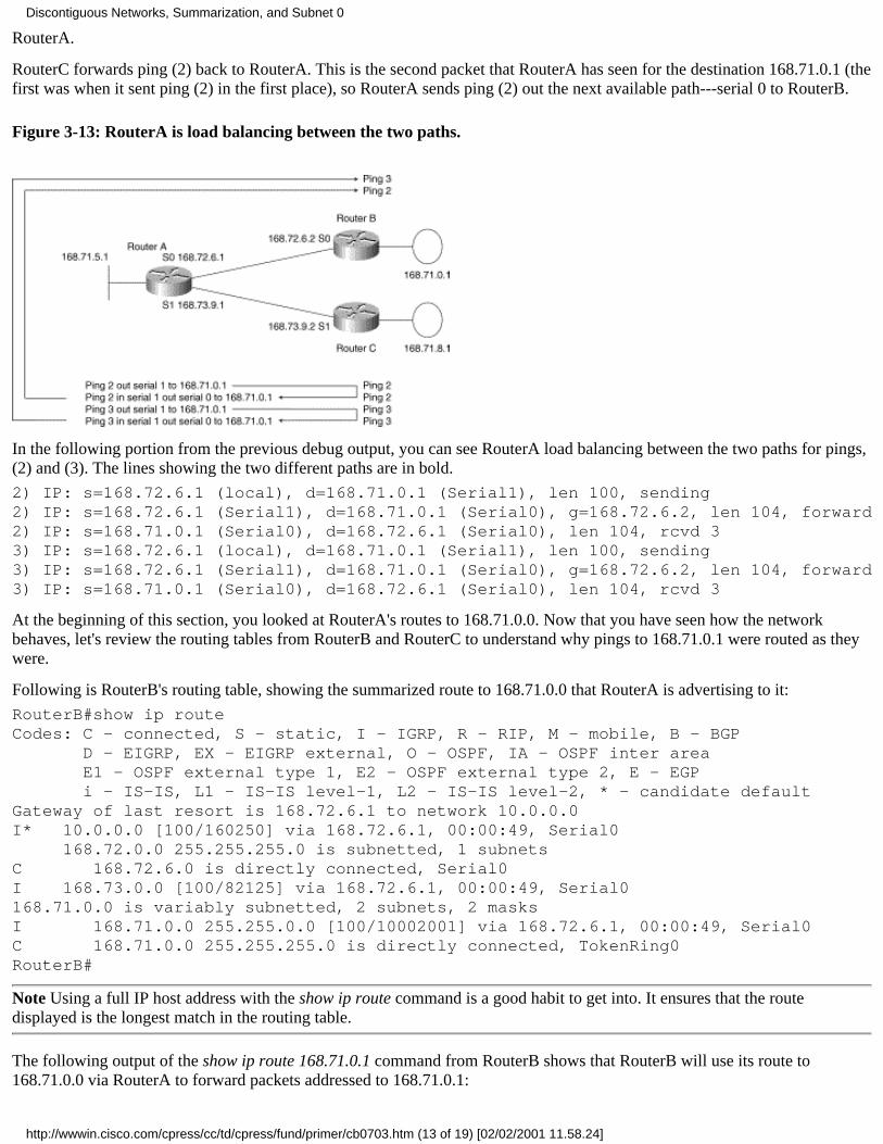
RouterA.
RouterC forwards ping (2) back to RouterA. This is the second packet that RouterA has seen for the destination 168.71.0.1 (thefirst was when it sent ping (2) in the first place), so RouterA sends ping (2) out the next available path---serial 0 to RouterB.
Figure 3-13: RouterA is load balancing between the two paths.
In the following portion from the previous debug output, you can see RouterA load balancing between the two paths for pings,(2) and (3). The lines showing the two different paths are in bold.
2) IP: s=168.72.6.1 (local), d=168.71.0.1 (Serial1), len 100, sending2) IP: s=168.72.6.1 (Serial1), d=168.71.0.1 (Serial0), g=168.72.6.2, len 104, forward2) IP: s=168.71.0.1 (Serial0), d=168.72.6.1 (Serial0), len 104, rcvd 33) IP: s=168.72.6.1 (local), d=168.71.0.1 (Serial1), len 100, sending3) IP: s=168.72.6.1 (Serial1), d=168.71.0.1 (Serial0), g=168.72.6.2, len 104, forward3) IP: s=168.71.0.1 (Serial0), d=168.72.6.1 (Serial0), len 104, rcvd 3
At the beginning of this section, you looked at RouterA's routes to 168.71.0.0. Now that you have seen how the networkbehaves, let's review the routing tables from RouterB and RouterC to understand why pings to 168.71.0.1 were routed as theywere.
Following is RouterB's routing table, showing the summarized route to 168.71.0.0 that RouterA is advertising to it:
RouterB#show ip routeCodes: C - connected, S - static, I - IGRP, R - RIP, M - mobile, B - BGP D - EIGRP, EX - EIGRP external, O - OSPF, IA - OSPF inter area E1 - OSPF external type 1, E2 - OSPF external type 2, E - EGP i - IS-IS, L1 - IS-IS level-1, L2 - IS-IS level-2, * - candidate defaultGateway of last resort is 168.72.6.1 to network 10.0.0.0I* 10.0.0.0 [100/160250] via 168.72.6.1, 00:00:49, Serial0 168.72.0.0 255.255.255.0 is subnetted, 1 subnetsC 168.72.6.0 is directly connected, Serial0I 168.73.0.0 [100/82125] via 168.72.6.1, 00:00:49, Serial0168.71.0.0 is variably subnetted, 2 subnets, 2 masksI 168.71.0.0 255.255.0.0 [100/10002001] via 168.72.6.1, 00:00:49, Serial0C 168.71.0.0 255.255.255.0 is directly connected, TokenRing0RouterB#
Note Using a full IP host address with the show ip route command is a good habit to get into. It ensures that the routedisplayed is the longest match in the routing table.
The following output of the show ip route 168.71.0.1 command from RouterB shows that RouterB will use its route to168.71.0.0 via RouterA to forward packets addressed to 168.71.0.1:
Discontiguous Networks, Summarization, and Subnet 0
http://wwwin.cisco.com/cpress/cc/td/cpress/fund/primer/cb0703.htm (13 of 19) [02/02/2001 11.58.24]

RouterB#show ip route 168.71.0.1Routing entry for 168.71.0.0 255.255.0.0 Known via "igrp 109", distance 100, metric 10002001 Redistributing via igrp 109 Last update from 168.72.6.1 on Serial0, 00:00:04 ago Routing Descriptor Blocks: * 168.72.6.1, from 168.72.6.1, 00:00:04 ago, via Serial0 Route metric is 10002001, traffic share count is 1 Total delay is 20010 microseconds, minimum bandwidth is 1 Kbit Reliability 255/255, minimum MTU 1500 bytes Loading 1/255, Hops 0RouterB#
Following is RouterC's routing table, which shows the summarized route to 168.71.0.0 that RouterA is advertising to it:
RouterC#show ip routeCodes: C - connected, S - static, I - IGRP, R - RIP, M - mobile, B - BGP D - EIGRP, EX - EIGRP external, O - OSPF, IA - OSPF inter area E1 - OSPF external type 1, E2 - OSPF external type 2, E - EGP i - IS-IS, L1 - IS-IS level-1, L2 - IS-IS level-2, * - candidate defaultGateway of last resort is 168.73.9.1 to network 10.0.0.0I* 10.0.0.0 [100/160250] via 168.73.9.1, 00:00:55, Serial1I 168.72.0.0 [100/82125] via 168.73.9.1, 00:00:55, Serial1 168.73.0.0 255.255.255.0 is subnetted, 1 subnetsC 168.73.9.0 is directly connected, Serial1168.71.0.0 is variably subnetted, 2 subnets, 2 masksC 168.71.8.0 255.255.255.0 is directly connected, TokenRing0I 168.71.0.0 255.255.0.0 [100/10002001] via 168.73.9.1, 00:00:56, Serial1RouterC#
Again, you can test whether the router will match the full IP host address (168.71.0.1) to the route:
RouterC#show ip route 168.71.0.1Routing entry for 168.71.0.0 255.255.0.0 Known via "igrp 109", distance 100, metric 10002001 Redistributing via igrp 109 Last update from 168.73.9.1 on Serial1, 00:01:09 ago Routing Descriptor Blocks: * 168.73.9.1, from 168.73.9.1, 00:01:09 ago, via Serial1 Route metric is 10002001, traffic share count is 1 Total delay is 20010 microseconds, minimum bandwidth is 1 Kbit Reliability 255/255, minimum MTU 1500 bytes Loading 1/255, Hops 0RouterC#
When Connectivity Is Not Possible
In the previous section, RouterA was able to ping 168.71.0.1 100 percent of the time. It was able to do so because it wasadvertising the summarized route of 168.71.0.0 for its connection to 168.71.5.0 to RouterB and RouterC. RouterC used thissummarized route to forward packets destined for 168.71.0.1 that were received from RouterA back to RouterA so thatRouterA could forward them over the next available path to RouterB.
In Figure 3-14 , RouterA no longer has a connection to a subnet of the 168.71.0.0 network, so it does not advertise thesummarized route to RouterB and RouterC. RouterA still has two summarized routes to 168.71.0.0 via RouterB and RouterC.However, RouterA can no longer ping 168.71.0.1 100 percent of the time.
Figure 3-14: RouterA no longer has a connection to a subnet of the 168.71.0.0 network.
Discontiguous Networks, Summarization, and Subnet 0
http://wwwin.cisco.com/cpress/cc/td/cpress/fund/primer/cb0703.htm (14 of 19) [02/02/2001 11.58.24]

RouterB and RouterC are summarizing their local subnets of 168.71.0.0 because of the different major network applied to theirserial interfaces. However, RouterA will not forward these entries to RouterB and RouterC due to a split horizon. (Recall thatthe term split horizon means not advertising routes back out the interface they were learned over.)
RouterA's new routing table shows the summarized routes to 168.71.0.0 and no local connection to 168.71.0.0:
RouterA#show ip routeCodes: C - connected, S - static, I - IGRP, R - RIP, M - mobile, B - BGP D - EIGRP, EX - EIGRP external, O - OSPF, IA - OSPF inter area E1 - OSPF external type 1, E2 - OSPF external type 2, E - EGP i - IS-IS, L1 - IS-IS level-1, L2 - IS-IS level-2, * - candidate defaultGateway of last resort is 171.68.207.129 to network 10.0.0.0S* 10.0.0.0 [1/0] via 171.68.207.129 168.72.0.0 255.255.255.0 is subnetted, 1 subnetsC 168.72.6.0 is directly connected, Serial0 168.73.0.0 255.255.255.0 is subnetted, 1 subnetsC 168.73.9.0 is directly connected, Serial1 168.74.0.0 255.255.255.0 is subnetted, 1 subnetsC 168.74.5.0 is directly connected, Ethernet0I 168.71.0.0 [100/80188] via 168.72.6.2, 00:00:42, Serial0 [100/80188] via 168.73.9.2, 00:00:04, Serial1RouterA#
RouterB's new routing table shows the local connection to 168.71.0.0 and no summarized routes to 168.71.0.0:
RouterB#show ip routeCodes: C - connected, S - static, I - IGRP, R - RIP, M - mobile, B - BGP D - EIGRP, EX - EIGRP external, O - OSPF, IA - OSPF inter area E1 - OSPF external type 1, E2 - OSPF external type 2, E - EGP i - IS-IS, L1 - IS-IS level-1, L2 - IS-IS level-2, * - candidate defaultGateway of last resort is 168.72.6.1 to network 10.0.0.0I* 10.0.0.0 [100/160250] via 168.72.6.1, 00:00:56, Serial0 168.72.0.0 255.255.255.0 is subnetted, 1 subnetsC 168.72.6.0 is directly connected, Serial0I 168.73.0.0 [100/82125] via 168.72.6.1, 00:00:56, Serial0I 168.74.0.0 [100/10002001] via 168.72.6.1, 00:00:56, Serial0168.71.0.0 255.255.255.0 is subnetted, 1 subnetsC 168.71.0.0 is directly connected, TokenRing0RouterB#
In this output of show ip route 168.71.0.0 from RouterB, you can see RouterB's connected route to 168.71.0.0. There is nosummarized route to 168.71.0.0:
RouterB#show ip route 168.71.0.0Routing entry for 168.71.0.0 255.255.255.0, 1 known subnets Attached (1 connections) Redistributing via igrp 109 Advertised by igrp 109C 168.71.0.0 is directly connected, TokenRing0
Discontiguous Networks, Summarization, and Subnet 0
http://wwwin.cisco.com/cpress/cc/td/cpress/fund/primer/cb0703.htm (15 of 19) [02/02/2001 11.58.24]

RouterB#
RouterC's new routing table shows the local connection to 168.71.8.0 and no summarized routes to 168.71.0.0:
RouterC#show ip routeCodes: C - connected, S - static, I - IGRP, R - RIP, M - mobile, B - BGP D - EIGRP, EX - EIGRP external, O - OSPF, IA - OSPF inter area E1 - OSPF external type 1, E2 - OSPF external type 2, E - EGP i - IS-IS, L1 - IS-IS level-1, L2 - IS-IS level-2, * - candidate defaultGateway of last resort is 168.73.9.1 to network 10.0.0.0I* 10.0.0.0 [100/160250] via 168.73.9.1, 00:00:35, Serial1I 168.72.0.0 [100/82125] via 168.73.9.1, 00:00:35, Serial1 168.73.0.0 255.255.255.0 is subnetted, 1 subnetsC 168.73.9.0 is directly connected, Serial1I 168.74.0.0 [100/10002001] via 168.73.9.1, 00:00:35, Serial1168.71.0.0 255.255.255.0 is subnetted, 1 subnetsC 168.71.8.0 is directly connected, TokenRing0RouterC#
In this output of show ip route 168.71.0.0 from RouterC, you can see RouterC is connected to 168.71.8.0. There is nosummarized route to 168.71.0.0:
RouterC#show ip route 168.71.0.0Routing entry for 168.71.0.0 255.255.255.0, 1 known subnets Attached (1 connections) Redistributing via rip, igrp 109 Advertised by igrp 109C 168.71.8.0 is directly connected, TokenRing0RouterC#
In this configuration, you can see that RouterA is only 60 percent successful pinging 168.71.0.1:
RouterA#ping 168.71.0.1Type escape sequence to abort.Sending 5, 100-byte ICMP Echos to 168.71.0.1, timeout is 2 seconds:!U!.!Success rate is 60 percent (3/5), round-trip min/avg/max = 4/4/4 msRouterA#
In this output from the debug ip packet and debug ip icmp commands from RouterA, taken while pinging 168.71.0.1, you cansee that pings (1), (3), and (5) are successful:
RouterA#debug ip packetRouterA#debug ip icmp(1) IP: s=168.72.6.1 (local), d=168.71.0.1 (Serial0), len 100, sending(1) IP: s=168.71.0.1 (Serial0), d=168.72.6.1 (Serial0), len 104, rcvd 3(1) ICMP: echo reply rcvd, src 168.71.0.1, dst 168.72.6.1(2) IP: s=168.72.6.1 (local), d=168.71.0.1 (Serial1), len 100, sending(2) IP: s=168.73.9.2 (Serial1), d=168.72.6.1, len 60, rcvd 4(2) ICMP: dst (168.72.6.1) host unreachable rcv from 168.73.9.2(3) IP: s=168.72.6.1 (local), d=168.71.0.1 (Serial0), len 100, sending(3) IP: s=168.71.0.1 (Serial0), d=168.72.6.1 (Serial0), len 104, rcvd 3(3) ICMP: echo reply rcvd, src 168.71.0.1, dst 168.72.6.1(4) IP: s=168.72.6.1 (local), d=168.71.0.1 (Serial1), len 100, sending(5) IP: s=168.72.6.1 (local), d=168.71.0.1 (Serial0), len 100, sending(5) IP: s=168.71.0.1 (Serial0), d=168.72.6.1 (Serial0), len 104, rcvd 3(5) ICMP: echo reply rcvd, src 168.71.0.1, dst 168.72.6.1RouterA#
Figure 3-15 shows the paths that the pings in this example took through the network.
Discontiguous Networks, Summarization, and Subnet 0
http://wwwin.cisco.com/cpress/cc/td/cpress/fund/primer/cb0703.htm (16 of 19) [02/02/2001 11.58.24]

Figure 3-15: A graphical representation of the paths used by the pings in this example.
Note debug ip icmp allows you to see exactly what ICMP messages are being received. Note that only one ICMP HostUnreachable is sent to RouterA. Having the routers limit ICMP Host Unreachable messages to hosts (in this case RouterA) thatsend more than one IP packet to an unreachable host over a short period of time keeps routers from being overwhelmed by thetask of creating and sending the ICMP messages.
In the debug messages from RouterA, the ICMP host unreachable message from RouterC is in response to ping (2). RouterCdoes not send an IP ICMP unreachable message for ping (4) because routers protect themselves from having to respond to toomany packets for unreachable hosts by ignoring some of them. Otherwise, malicious people could tie up a router's CPU bybarraging the router with packets to unreachable hosts.
The following extract from the output of the debug ip packet and debug ip icmp commands from RouterC shows only themessages related to the packets RouterA sent to RouterC:
RouterC#debug ip packetRouterC#debug ip icmp(2) IP: s=168.72.6.1 (Serial1), d=168.71.0.1, len 104, unroutable(2) ICMP: dst (168.71.0.1) host unreachable sent to 168.72.6.1(2) IP: s=168.73.9.2 (local), d=168.72.6.1 (Serial1), len 32, sending(4) IP: s=168.72.6.1 (Serial1), d=168.71.0.1, len 104, unroutableRouterC#
Alternating Paths for the First Ping
If you stage a scenario like the previous one in a lab, you will notice that the number of successful pings will be inconsistentfrom one test to another. This is because when a router believes that it has two or more viable paths to a destination, it willalternate between them when sending the first ping. The remainder of this section explains this phenomenon in more detail.This behavior is not related to the routing protocol in use.
The following output from RouterA shows that RouterA will alternate which route to 168.71.0.0 it uses first so that the failureswill vary from time to time.
Using serial 1 first results in the following output:
RouterA#ping 168.71.0.1Type escape sequence to abort.Sending 5, 100-byte ICMP Echos to 168.71.0.1, timeout is 2 seconds:U!.!USuccess rate is 40 percent (2/5), round-trip min/avg/max = 4/4/4 ms
Discontiguous Networks, Summarization, and Subnet 0
http://wwwin.cisco.com/cpress/cc/td/cpress/fund/primer/cb0703.htm (17 of 19) [02/02/2001 11.58.24]
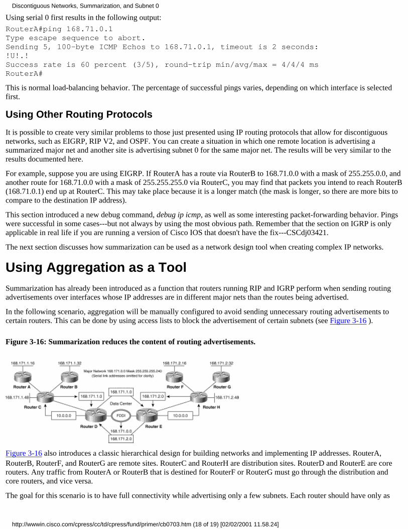
Using serial 0 first results in the following output:
RouterA#ping 168.71.0.1Type escape sequence to abort.Sending 5, 100-byte ICMP Echos to 168.71.0.1, timeout is 2 seconds:!U!.!Success rate is 60 percent (3/5), round-trip min/avg/max = 4/4/4 msRouterA#
This is normal load-balancing behavior. The percentage of successful pings varies, depending on which interface is selectedfirst.
Using Other Routing Protocols
It is possible to create very similar problems to those just presented using IP routing protocols that allow for discontiguousnetworks, such as EIGRP, RIP V2, and OSPF. You can create a situation in which one remote location is advertising asummarized major net and another site is advertising subnet 0 for the same major net. The results will be very similar to theresults documented here.
For example, suppose you are using EIGRP. If RouterA has a route via RouterB to 168.71.0.0 with a mask of 255.255.0.0, andanother route for 168.71.0.0 with a mask of 255.255.255.0 via RouterC, you may find that packets you intend to reach RouterB(168.71.0.1) end up at RouterC. This may take place because it is a longer match (the mask is longer, so there are more bits tocompare to the destination IP address).
This section introduced a new debug command, debug ip icmp, as well as some interesting packet-forwarding behavior. Pingswere successful in some cases---but not always by using the most obvious path. Remember that the section on IGRP is onlyapplicable in real life if you are running a version of Cisco IOS that doesn't have the fix---CSCdj03421.
The next section discusses how summarization can be used as a network design tool when creating complex IP networks.
Using Aggregation as a ToolSummarization has already been introduced as a function that routers running RIP and IGRP perform when sending routingadvertisements over interfaces whose IP addresses are in different major nets than the routes being advertised.
In the following scenario, aggregation will be manually configured to avoid sending unnecessary routing advertisements tocertain routers. This can be done by using access lists to block the advertisement of certain subnets (see Figure 3-16 ).
Figure 3-16: Summarization reduces the content of routing advertisements.
Figure 3-16 also introduces a classic hierarchical design for building networks and implementing IP addresses. RouterA,RouterB, RouterF, and RouterG are remote sites. RouterC and RouterH are distribution sites. RouterD and RouterE are corerouters. Any traffic from RouterA or RouterB that is destined for RouterF or RouterG must go through the distribution andcore routers, and vice versa.
The goal for this scenario is to have full connectivity while advertising only a few subnets. Each router should have only as
Discontiguous Networks, Summarization, and Subnet 0
http://wwwin.cisco.com/cpress/cc/td/cpress/fund/primer/cb0703.htm (18 of 19) [02/02/2001 11.58.24]

much routing information as absolutely necessary.
The FDDI ring has 10.0.0.0 assigned to it. RouterD and RouterE each advertise this major net to their distribution routers,which accept it as a major net advertisement. The distribution routers advertise this major net to their respective remoterouters, which also accept it as a major net advertisement.
All distribution and remote routers are configured to use their routes to 10.0.0.0 to forward packets for networks they have noknowledge of. The method for doing this is explained in more detail in "Default Routing."
The distribution routers must know about the subnets their remote routers have configured. RouterC must know that RouterAhas 168.71.1.16 and that RouterB has 168.71.1.32. This can be done by manually configuring these routes into RouterC or byallowing RouterA and RouterB to advertise their networks to RouterC. RouterC already knows it is connected to 168.71.1.48.
In any case, RouterC only needs to advertise subnet 168.71.1.0 to RouterD because all subnets that start with the prefix168.71.1.0 are in some way reachable via RouterC. The same holds for RouterH---it only has to advertise the prefix 168.71.2.0to RouterE because all subnets with this prefix are reachable via RouterH. Only RouterD and RouterE need to know how toreach prefixes 168.71.1.0 and 168.71.2.0.
You can see that, in this design, all packets for subnets that the distribution and remote routers have no knowledge of willeventually arrive at the core routers. The core routers will drop any packets destined to subnets that they have no knowledgeof.
It is imperative that the core routers are not configured to send any packets for subnets they have no knowledge of to eachother---this would result in a loop.
This scenario shows how careful use of subnetting at distribution and remote sites can greatly reduce the amount of routinginformation necessary to maintain full connectivity throughout a network.
SummaryThis chapter has covered the problems that can occur when using subnet 0, discontiguous networks, and summarized routeswith RIP and IGRP. The use of discontiguous networks to cause summarization was discussed. Summarized routes werecompared to subnet 0 in order to explain how they can be confused with one another. Recall that IGRP worked in somescenarios because of the anomalous behavior that allowed it to accept a major net advertisement even though it had a localconnection to the same major net. In fact, RIP and IGRP should behave exactly the same when faced with major netadvertisements for networks they have direct connections to---they should ignore the major net advertisement.
EIGRP, OSPF, and RIP V2 were not covered because they have built-in methods for coping with these issues. However, evenEIGRP, OSPF, and RIP V2 can fail when using subnet 0 and summarization if configured incorrectly. The informationprovided in this chapter also explained why RIP and IGRP fail when using discontiguous networks.
Using aggregation as a tool in designing networks was also discussed. It can greatly simplify routing tables and the debuggingof IP connectivity problems. "Using IP Unnumbered and VLSM," continues this discussion with explanations of IPunnumbered and VLSM.
Posted: Wed Mar 3 09:59:48 PST 1999Copyright 1989-1999©Cisco Systems Inc.Copyright © 1997 Macmillan Publishing USA, a Simon & Schuster Company
Discontiguous Networks, Summarization, and Subnet 0
http://wwwin.cisco.com/cpress/cc/td/cpress/fund/primer/cb0703.htm (19 of 19) [02/02/2001 11.58.24]

Table of Contents
Using IP Unnumbered and VLSM
Understanding IP UnnumberedIP Unnumbered Causes Host Routes and Lost ConnectivityHost RoutesHosts Routes Using DDR
Configuring IP Unnumbered on Serial InterfacesRIP and IGRP Behave the SameRIP with IP Unnumbered Configured Properly
Displaying the RoutesSending Routing UpdatesPinging the Interfaces
RIP with IP Unnumbered Configured ImproperlyExamples of Routing Updates
Host Route ProblemLost Routes Problem
Using a Different Subnet Mask and a Different Major Net
Understanding VLSMVLSM Using RIP and IGRPVLSM Experiment Using Two RoutersVLSM Experiment Using Three RoutersCorrectly Configuring VLSM Blocked RoutesVLSM Summary
Summary
Using IP Unnumbered and VLSMThis chapter is broken into two sections. The first section discusses IP unnumbered. It provides scenarios showing howit works when properly configured and how it breaks when improperly configured.
The second section discusses variable length subnet masking (VLSM). It provides scenarios showing how it workswhen properly configured and how it breaks when improperly configured.
Before proceeding any further in this chapter, it is important to lay the groundwork for the discussion by defining thefollowing terms:
IP unnumbered refers to using the network or subnet address of a local LAN interface as the router's network orsubnetwork address for a point-to-point serial link. The term point-to-point means that only two devices are onthe link, as is the case on a T1 connection between two routers or a point-to-point subinterface to a Frame Relaynetwork. Normally, a serial link has its own unique network or subnetwork address. IP unnumbered allows anetwork administrator to conserve network or subnetwork addresses. IP unnumbered is especially valuable fornetworks running IP routing protocols such as RIP V1 and IGRP, which do not support VLSM. Without VLSM
●
Using IP Unnumbered and VLSM
http://wwwin.cisco.com/cpress/cc/td/cpress/fund/primer/cb0704.htm (1 of 19) [02/02/2001 11.58.54]
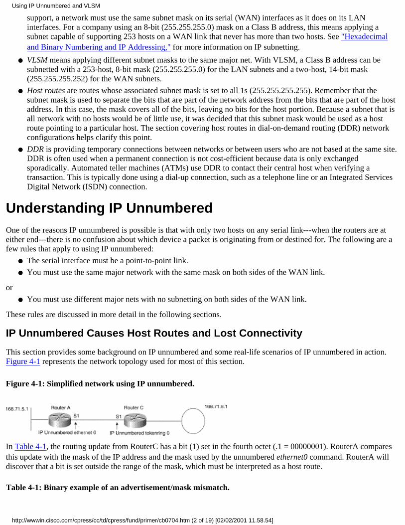
support, a network must use the same subnet mask on its serial (WAN) interfaces as it does on its LANinterfaces. For a company using an 8-bit (255.255.255.0) mask on a Class B address, this means applying asubnet capable of supporting 253 hosts on a WAN link that never has more than two hosts. See "Hexadecimaland Binary Numbering and IP Addressing," for more information on IP subnetting.
VLSM means applying different subnet masks to the same major net. With VLSM, a Class B address can besubnetted with a 253-host, 8-bit mask (255.255.255.0) for the LAN subnets and a two-host, 14-bit mask(255.255.255.252) for the WAN subnets.
●
Host routes are routes whose associated subnet mask is set to all 1s (255.255.255.255). Remember that thesubnet mask is used to separate the bits that are part of the network address from the bits that are part of the hostaddress. In this case, the mask covers all of the bits, leaving no bits for the host portion. Because a subnet that isall network with no hosts would be of little use, it was decided that this subnet mask would be used as a hostroute pointing to a particular host. The section covering host routes in dial-on-demand routing (DDR) networkconfigurations helps clarify this point.
●
DDR is providing temporary connections between networks or between users who are not based at the same site.DDR is often used when a permanent connection is not cost-efficient because data is only exchangedsporadically. Automated teller machines (ATMs) use DDR to contact their central host when verifying atransaction. This is typically done using a dial-up connection, such as a telephone line or an Integrated ServicesDigital Network (ISDN) connection.
●
Understanding IP UnnumberedOne of the reasons IP unnumbered is possible is that with only two hosts on any serial link---when the routers are ateither end---there is no confusion about which device a packet is originating from or destined for. The following are afew rules that apply to using IP unnumbered:
The serial interface must be a point-to-point link.●
You must use the same major network with the same mask on both sides of the WAN link.●
or
You must use different major nets with no subnetting on both sides of the WAN link.●
These rules are discussed in more detail in the following sections.
IP Unnumbered Causes Host Routes and Lost Connectivity
This section provides some background on IP unnumbered and some real-life scenarios of IP unnumbered in action.Figure 4-1 represents the network topology used for most of this section.
Figure 4-1: Simplified network using IP unnumbered.
In Table 4-1, the routing update from RouterC has a bit (1) set in the fourth octet (.1 = 00000001). RouterA comparesthis update with the mask of the IP address and the mask used by the unnumbered ethernet0 command. RouterA willdiscover that a bit is set outside the range of the mask, which must be interpreted as a host route.
Table 4-1: Binary example of an advertisement/mask mismatch.
Using IP Unnumbered and VLSM
http://wwwin.cisco.com/cpress/cc/td/cpress/fund/primer/cb0704.htm (2 of 19) [02/02/2001 11.58.54]

Advertised mask 168.71.8.1 = 10101000.01000111.00001000.00000001Router's mask 255.255.255.0 = 11111111.11111111.11111111.00000000
See the section on mask ambiguity in "Discontiguous Networks, Summarization, and Subnet 0," for more informationon this issue.
Host Routes
As previously explained, a host route refers to a route whose associated mask has all 32 bits set to 1---255.255.255.255.For an address and mask such as this, there can be only one host.
One common cause of host routes is a route advertisement that has bits set in the range that the receiving routerinterprets as outside of the subnet mask. In this case, the router compared the advertisement received from an adjacentrouter with the mask of the interface it was received over and found a mismatch. This is how RIP V1 and IGRPdetermine the mask to apply to advertisements they receive.
Table 4-1 shows an example of an advertisement that has a bit set to 1 in a region of the address not covered by thesubnet mask in use.
Another common cause of host routes is a routing update explicitly advertised with a mask of 255.255.255.255.Routing protocols such as OSPF and EIGRP include the masks associated with the routes in their routing updates.
Host routes are also often manually configured to resolve routing problems related to configuring dial-on-demandrouting (DDR). The following section on DDR goes into more detail on this subject.
Hosts Routes Using DDR
Dial-up users may require host routes to ensure that they have full connectivity to the network. Although dial-upnetworking is beyond the scope of this book, this section attempts to clarify when host routes can be useful. In thescenario in Figure 4-2, hosts A and B use modems to dial into the corporate network.
Figure 4-2: Async dial-up network using IP unnumbered without host routes.
In Figure 4-2, RouterA is using IP unnumbered ethernet 0 on its Async interfaces. This results in multiple Asyncinterfaces sharing the same subnet as a local Ethernet. However, the router needs to be able to keep track of theinterfaces as separate subnets in order to route traffic correctly.
Remember that one of the rules of IP unnumbered is that it must be used only for point-to-point network connections.Extending the mask already applied to RouterA's Ethernet 0 interface when the addresses are configured on theasynchronous interfaces provides this point-to-point connection. Interface Async1 has an address of 168.71.48.2255.255.255.255, and interface Async2 has an address of 168.71.48.3 255.255.255.255.
Using IP Unnumbered and VLSM
http://wwwin.cisco.com/cpress/cc/td/cpress/fund/primer/cb0704.htm (3 of 19) [02/02/2001 11.58.54]

When all of the hosts are connected to RouterA (they have dialed in to the network), they will have their own uniqueroutes (their host routes) in RouterA's routing table. If RouterA receives a packet for 168.71.48.4 from HostA, it does alongest match lookup of its routing table and determines that the best match is the subnet applied to its Ethernet 0interface: 168.71.48.0. It forwards the packet out of that interface.
On the other hand, if RouterA receives a packet for 168.71.48.2 from HostB, the longest match lookup results in amatch for the host route applied to Asynch1: 168.71.48.2. The packet is forwarded out that interface to HostA(assuming either that the link to HostA is already up or that RouterA is configured to place a call to HostA when itreceives a packet for it).
Without host routes being advertised by RouterA to RouterB for end systems A and B, RouterB assumes that an IPpacket to 171.68.48.2 or 171.68.48.3 is for an end system on the Ethernet network connecting RouterA and RouterB.The gray box surrounding the (E0) interfaces for routers A and B in Figure 4-2 shows where RouterB assumes thataddresses 171.68.48.2 and 171.68.48.3 reside. RouterB ARPs (attempts to determine the layer two MAC address) for171.68.48.2 or 171.68.48.3 directly instead of forwarding the packet to RouterA to reach end system A.
Note If you do not understand the role of the Address Resolution Protocol (ARP), refer to "Bridging IP BetweenDissimilar Media," or RFC 826.
In Figure 4-3, RouterA is advertising the host routes for end systems A and B. RouterB will do a longest match lookupfor packets to either 171.68.48.2 or 171.68.48.3 and discover that the connected route to 171.68.48.0 is not the longestmatch. RouterB will determine that these routes are reachable via its Ethernet 0 address, using RouterA as the next hop.
Figure 4-3: Async dial-up network using IP unnumbered with host routes.
The gray box surrounding HostA and HostB in Figure 4-3 shows where RouterB will assume that addresses171.68.48.2 and 171.68.48.3 reside now that the correct host routes are being advertised by RouterA.
This section has given you an intentionally simplistic example of DDR. DDR is an incredibly complex subject that cantake up an entire book all by itself. Consult the documentation for the version of Cisco IOS you are using for moreinformation on DDR internetworking. The next section explains how to configure IP unnumbered in non-DDRsituations.
Configuring IP Unnumbered on Serial InterfacesConfiguring IP unnumbered for RIP and IGRP is done in the same way as explained previously. The excerpts from theconfigurations of RouterA and RouterC that follow show how to configure IP unnumbered on a serial interface.
!hostname RouterA!
Using IP Unnumbered and VLSM
http://wwwin.cisco.com/cpress/cc/td/cpress/fund/primer/cb0704.htm (4 of 19) [02/02/2001 11.58.54]
interface serial1ip unnumbered Ethernet0!!hostname RouterC!interface serial1ip unnumbered TokenRing0!
The following show interface commands from RouterA and RouterC show that IP unnumbered is now in use on bothserial interfaces.
RouterA#show interface serial 1Serial1 is up, line protocol is up Hardware is HD64570 Interface is unnumbered. Using address of Ethernet0 (168.71.5.1) MTU 1500 bytes, BW 128 Kbit, DLY 20000 usec, rely 255/255, load 1/255RouterC#show interface serial 1Serial1 is up, line protocol is up Hardware is HD64570 Interface is unnumbered. Using address of TokenRing0 (168.71.8.1) MTU 1500 bytes, BW 128 Kbit, DLY 20000 usec, rely 255/255, load 1/255
RIP and IGRP Behave the Same
The rules governing the successful configuration of IP unnumbered that were given at the start of this chapter apply toRIP V1 and IGRP equally. When properly configured, both protocols behave in the same manner. All of the materialpresented in the following scenario, which shows the proper configuration of IP unnumbered using RIP, applies toIGRP as well.
Improper configuration of IP unnumbered causes both RIP V1 and IGRP to lose IP connectivity for the misconfiguredsubnets. The failure modes for RIP and IGRP are slightly different because IGRP doesn't support host routes as well asRIP. However, this difference is not sufficient to warrant providing separate scenarios that show both routing protocolsfailing when IP unnumbered is misconfigured. By applying the concepts presented in this scenario, you should be ableto understand what is going wrong when you are faced with a network in which IGRP has been configured with animproper use of IP unnumbered.
This section is broken into the following three scenarios:
RIP with IP unnumbered configured properly.●
This section shows IP unnumbered working as intended and provides insights into proving that it is working asintended.
●
RIP with IP unnumbered configured improperly---a different subnet mask was used.●
This section shows IP unnumbered not working as intended because an improper subnet mask has been applied.It also provides some insights into proving that it is not working as intended.
●
RIP with IP unnumbered configured improperly---a different subnet mask and a different major net were used.●
This section combines the use of different major networks with a misconfiguration caused by using a subnetmask on one of the networks. It shows how IP unnumbered works with different major nets as well as how theuse of a subnet masked major net can cause problems in some configurations.
●
Using IP Unnumbered and VLSM
http://wwwin.cisco.com/cpress/cc/td/cpress/fund/primer/cb0704.htm (5 of 19) [02/02/2001 11.58.54]

RIP with IP Unnumbered Configured Properly
In this scenario, RIP has been properly configured with IP unnumbered. The examples show how to verify the properconfiguration of IP unnumbered.
Displaying the Routes
In the following output of the show ip route command from RouterA, you can see that RouterA has a route to168.71.8.0:
RouterA#show ip route 168.71.8.1Routing entry for 168.71.8.0 255.255.255.0 Known via "rip", distance 120, metric 1 Redistributing via rip Last update from 168.71.8.1 on Serial1, 00:00:13 ago Routing Descriptor Blocks: * 168.71.8.1, from 168.71.8.1, 00:00:13 ago, via Serial1 Route metric is 1, traffic share count is 1RouterA#
In the following output of the show ip route command from RouterC, you can see that RouterC has a route to168.71.5.0:
RouterC#show ip route 168.71.5.1Routing entry for 168.71.5.0 255.255.255.0 Known via "rip", distance 120, metric 1 Redistributing via rip Advertised by rip (self originated) Last update from 168.71.5.1 on Serial1, 00:00:13 ago Routing Descriptor Blocks: * 168.71.5.1, from 168.71.5.1, 00:00:13 ago, via Serial1 Route metric is 1, traffic share count is 1RouterC#
Notice that in both of the previous routing tables, the last update from address is the same as the actual address used inthe show ip route command. Note that the routing entry indicates that this is a subnetted Class B address and not a hostroute because the mask is 255.255.255.0. This is the expected behavior when IP unnumbered is configured correctly. IfIP unnumbered had been configured incorrectly, the routing entry would have a host route mask of 255.255.255.255.
Sending Routing Updates
The following output of debug ip rip from RouterA shows RouterA advertising the summarized major network of168.71.0.0:
RouterA#debug ip ripRIP: sending update to 255.255.255.255 via Serial1 (168.71.5.1) subnet 168.71.5.0, metric 1 default 0.0.0.0, metric 1 network 168.71.0.0, metric 1RIP: received update from 168.71.8.1 on Serial1 168.71.8.0 in 1 hops 168.71.0.0 in 1 hops
The following output of debug ip rip from RouterC shows RouterC advertising the summarized major network of168.71.0.0:
Using IP Unnumbered and VLSM
http://wwwin.cisco.com/cpress/cc/td/cpress/fund/primer/cb0704.htm (6 of 19) [02/02/2001 11.58.54]

RouterC#deb ip ripRIP: sending update to 255.255.255.255 via Serial1 (168.71.8.1) subnet 168.71.8.0, metric 1 network 168.71.0.0, metric 1RIP: received update from 168.71.5.1 on Serial1 168.71.5.0 in 1 hops 0.0.0.0 in 1 hops 168.71.0.0 in 1 hops
Although both routers are advertising the summarized major net of 168.71.0.0 to each other, neither router will installthe route while using RIP because they have local connections to the 168.71.0.0 major net. This was explained in"Discontiguous Networks, Summarization, and Subnet 0," in the section on summarization.
Pinging the Interfaces
In the following output, which is from RouterA pinging 168.71.8.1, you can see that the pings are successful:
RouterA#ping 168.71.8.1Type escape sequence to abort.Sending 5, 100-byte ICMP Echos to 168.71.8.1, timeout is 2 seconds:!!!!!Success rate is 100 percent (5/5), round-trip min/avg/max = 16/17/20 msRouterA#
In the following output, which is from RouterC pinging 168.71.5.1, you can see that the pings are successful:
RouterC#ping 168.71.5.1Type escape sequence to abort.Sending 5, 100-byte ICMP Echos to 168.71.5.1, timeout is 2 seconds:!!!!!Success rate is 100 percent (5/5), round-trip min/avg/max = 16/16/16 msRouterC#
The fact that the pings are successful is the final proof that IP unnumbered has been configured correctly. Strictlyspeaking, this step is unnecessary as long as the results from the show ip route command indicate that proper routeshave been installed. However, it is always better to double-check proper configuration by pinging the addresses.
The next section is a scenario about what happens when IP unnumbered has been misconfigured.
RIP with IP Unnumbered Configured Improperly
This scenario shows what happens when the rule is violated that requires the same mask to be used on all occurrencesof the same major network's subnets. In Figure 4-4, RouterC's Token Ring interface now has a mask of255.255.255.240. This is an example of variable length subnet masking (VLSM). In this case, major network168.71.0.0 now has two masks: 255.255.255.0 and 255.255.255.240. VLSM is discussed in more detail in the nextsection.
Figure 4-4: An incorrect mask has been applied to RouterC's Token Ring interface.
Using IP Unnumbered and VLSM
http://wwwin.cisco.com/cpress/cc/td/cpress/fund/primer/cb0704.htm (7 of 19) [02/02/2001 11.58.54]

In the following output of the show interface commands from RouterC, you can see the new mask in use. Note that noreference to the mask used on Token Ring 0 is in the output from serial 1. You must always check the interface that theaddress is being derived from to determine which subnet mask is in use.
RouterC#show interface tokenring 0TokenRing0 is up, line protocol is up Hardware is TMS380, address is 0000.30c8.ab75 (bia 0000.30c8.ab75) Internet address is 168.71.8.17 255.255.255.240RouterC#show interface serial 1Serial1 is up, line protocol is up Hardware is HD64570 Interface is unnumbered. Using address of TokenRing0 (168.71.8.17) MTU 1500 bytes, BW 128 Kbit, DLY 20000 usec, rely 255/255, load 1/255
Note When you are troubleshooting IP unnumbered problems always check the show interface command from theinterface that is providing the address.
Examples of Routing Updates
The output of the debug ip routing and ip rip commands from RouterA shows what happens when RouterA adds thesubnet route to 168.71.8.16. Note the statement indicating that network 168.71.0.0 is now variably masked. This is inresponse to RouterA comparing the routing update to its IP address and mask on ethernet 0. Note also that RouterAbelieves that the next hop address for 168.71.8.16 255.255.255.255 is 168.71.8.17.
RouterA#debug ip routingRouterA#debug ip ripRouterA# clear ip route 168.71.8.16RT: del 168.71.8.16 255.255.255.255 via 168.71.8.17, rip metric [120/1]RT: delete subnet route to 168.71.8.16 255.255.255.255RIP: received update from 168.71.8.17 on Serial1 168.71.8.16 in 1 hops 168.71.0.0 in 1 hopsRT: network 168.71.0.0 is now variably maskedRT: add 168.71.8.16 255.255.255.255 via 168.71.8.17, rip metric [120/1]RouterA#
RouterA has now installed a host route to 168.71.8.16 in its routing table because the advertisement received fromRouterC had bits set in what RouterA believes is the host portion of the address.
RouterA's mask for the 168.71.0.0 network is 255.255.255.0. The advertisement was for 168.71.8.16. The 16 in thefourth octet should not be there for a routing advertisement of a subnet with a 255.255.255.0 mask. Routers use themask of the interface that received the update to determine the appropriate mask to apply.
RouterA#show ip routeCodes: C - connected, S - static, I - IGRP, R - RIP, M - mobile, B - BGP D - EIGRP, EX - EIGRP external, O - OSPF, IA - OSPF inter area E1 - OSPF external type 1, E2 - OSPF external type 2, E - EGP
Using IP Unnumbered and VLSM
http://wwwin.cisco.com/cpress/cc/td/cpress/fund/primer/cb0704.htm (8 of 19) [02/02/2001 11.58.54]

i - IS-IS, L1 - IS-IS level-1, L2 - IS-IS level-2, * - candidate defaultGateway of last resort is 171.68.207.129 to network 10.0.0.0S* 10.0.0.0 [1/0] via 171.68.207.129168.71.0.0 is variably subnetted, 2 subnets, 2 masksC 168.71.5.0 255.255.255.0 is directly connected, Ethernet0R 168.71.8.16 255.255.255.255 [120/1] via 168.71.8.17, 00:00:13, Serial1S* 0.0.0.0 0.0.0.0 [1/0] via 171.68.207.129RouterA#
Host Route Problem
The following output of the show ip route command and the routing table from RouterA shows that RouterA does nothave a route it can use for a packet to 168.71.8.17. Even though it has a route to 168.71.8.16, the subnet that the hostaddress of 168.71.8.17 should be on, RouterA does not have such a route because the route to 168.71.8.16 is a hostroute.
RouterA#show ip route 168.71.8.17% Subnet not in tableRouterA#RouterA#show ip route 168.71.0.0Routing entry for 168.71.0.0 255.255.0.0, 2 known subnets Attached (1 connections) Variably subnetted with 2 masks Redistributing via rip Advertised by ripC 168.71.5.0 255.255.255.0 is directly connected, Ethernet0R 168.71.8.16 255.255.255.255 [120/1] via 168.71.8.17, 00:00:01, Serial1RouterA#
When RouterA does a longest match lookup for the destination IP address 168.71.8.17 in its routing table, the maskassociated with the route determines the number of bits that must match. In the case of its route to 168.71.8.16, all 32bits would have to match exactly because the mask is 255.255.255.255. 168.71.8.16 and 168.71.8.17 are different at the32nd bit and are therefore not a match.
The routing table also shows that RouterA does not have a summarized route to 168.71.0.0, even though RouterC isadvertising it.
Lost Routes Problem
In the following routing table from RouterC, you can see that RouterC has a route to 168.71.5.0, which it uses to routepackets destined for 168.71.5.1:
RouterC#show ip routeCodes: C - connected, S - static, I - IGRP, R - RIP, M - mobile, B - BGP D - EIGRP, EX - EIGRP external, O - OSPF, IA - OSPF inter area E1 - OSPF external type 1, E2 - OSPF external type 2, E - EGP i - IS-IS, L1 - IS-IS level-1, L2 - IS-IS level-2, * - candidate defaultGateway of last resort is 168.71.5.1 to network 0.0.0.0R 10.0.0.0 [120/1] via 168.71.5.1, 00:00:14, Serial1168.71.0.0 255.255.255.240 is subnetted, 2 subnetsR 168.71.5.0 [120/1] via 168.71.5.1, 00:00:15, Serial1C 168.71.8.16 is directly connected, TokenRing0R* 0.0.0.0 0.0.0.0 [120/1] via 168.71.5.1, 00:00:15, Serial1RouterC#
Using IP Unnumbered and VLSM
http://wwwin.cisco.com/cpress/cc/td/cpress/fund/primer/cb0704.htm (9 of 19) [02/02/2001 11.58.54]

In the following output of the debug ip packet command from RouterC, you can see that RouterC sends the pingsdestined for 168.71.5.1 out serial 1. Note that the source address of the pings is 168.71.8.17. This is the host addressthat RouterA cannot reach because the route it should use to the subnet of 168.71.8.16 has the wrong mask.
RouterC#deb ip packetRouterC#ping 168.71.5.1Type escape sequence to abort.Sending 5, 100-byte ICMP Echos to 168.71.5.1, timeout is 2 seconds:IP: s=168.71.8.17 (local), d=168.71.5.1 (Serial1), len 100, sending.IP: s=168.71.8.17 (local), d=168.71.5.1 (Serial1), len 100, sending.IP: s=168.71.8.17 (local), d=168.71.5.1 (Serial1), len 100, sending.IP: s=168.71.8.17 (local), d=168.71.5.1 (Serial1), len 100, sendingIP: s=168.71.8.17 (local), d=168.71.5.1 (Serial1), len 100, sending.Success rate is 0 percent (0/5)RouterC#
The following output from the debug ip packet command on RouterA shows that RouterA receives the pings fromRouterC but cannot route the responses. Configuring IP unnumbered incorrectly by applying a different mask onRouterC's Token Ring interface has made connectivity between the two routers impossible.
RouterA#debug ip packetIP: s=168.71.8.17 (Serial1), d=168.71.5.1, len 104, rcvd 4IP: s=168.71.5.1 (local), d=168.71.8.17, len 104, unroutableIP: s=168.71.8.17 (Serial1), d=168.71.5.1, len 104, rcvd 4IP: s=168.71.5.1 (local), d=168.71.8.17, len 104, unroutableIP: s=168.71.8.17 (Serial1), d=168.71.5.1, len 104, rcvd 4IP: s=168.71.5.1 (local), d=168.71.8.17, len 104, unroutableIP: s=168.71.8.17 (Serial1), d=168.71.5.1, len 104, rcvd 4IP: s=168.71.5.1 (local), d=168.71.8.17, len 104, unroutableIP: s=168.71.8.17 (Serial1), d=168.71.5.1, len 104, rcvd 4IP: s=168.71.5.1 (local), d=168.71.8.17, len 104, unroutableIP: s=168.71.8.17 (Serial1), d=255.255.255.255, len 76, rcvd 2RouterA#
This section has explained why IP unnumbered requires that the same mask be used on all subnets of the same majornet. When a different mask is used, routers cannot properly derive the masks for routes they receive. Instead, theyresort to installing host routes for these advertisements. As this section has proven, host routes do not allow for full IPconnectivity. The next section explains how IP unnumbered works with different major networks.
Using a Different Subnet Mask and a Different Major Net
Using a different major network with no subnet masking on both routers gives similar results to a proper configurationthat uses the same major network and the same subnet mask. In the case of different major networks, the routers simplyadvertise their summarized routes to each other. Each router installs the other's summarized route, and full connectivityis possible.
To avoid repetition, this section begins with a misconfiguration of IP unnumbered. Recall that a misconfiguration of asubnet mask using the same major net on both routers causes connectivity to be broken. In this scenario, connectivity isstill possible but the misconfiguration results in some other problems.
A different major network---168.72.0.0---has been configured on RouterC's Token Ring interface; see Figure 4-5. Inaddition, a subnet mask has been added---255.255.255.0. RouterA still has its original IP unnumbered address of168.71.5.1 255.255.255.0. Using a subnet mask on both major nets is a violation of the IP unnumbered rule that statesas follows: When using different major nets, no subnetting is allowed.
Using IP Unnumbered and VLSM
http://wwwin.cisco.com/cpress/cc/td/cpress/fund/primer/cb0704.htm (10 of 19) [02/02/2001 11.58.54]
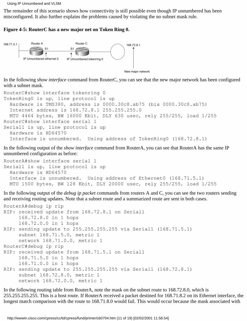
The remainder of this scenario shows how connectivity is still possible even though IP unnumbered has beenmisconfigured. It also further explains the problems caused by violating the no subnet mask rule.
Figure 4-5: RouterC has a new major net on Token Ring 0.
In the following show interface command from RouterC, you can see that the new major network has been configuredwith a subnet mask.
RouterC#show interface tokenring 0TokenRing0 is up, line protocol is up Hardware is TMS380, address is 0000.30c8.ab75 (bia 0000.30c8.ab75) Internet address is 168.72.8.1 255.255.255.0 MTU 4464 bytes, BW 16000 Kbit, DLY 630 usec, rely 255/255, load 1/255RouterC#show interface serial 1Serial1 is up, line protocol is up Hardware is HD64570 Interface is unnumbered. Using address of TokenRing0 (168.72.8.1)
In the following output of the show interface command from RouterA, you can see that RouterA has the same IPunnumbered configuration as before:
RouterA#show interface serial 1Serial1 is up, line protocol is up Hardware is HD64570 Interface is unnumbered. Using address of Ethernet0 (168.71.5.1) MTU 1500 bytes, BW 128 Kbit, DLY 20000 usec, rely 255/255, load 1/255
In the following output of the debug ip packet commands from routers A and C, you can see the two routers sendingand receiving routing updates. Note that a subnet route and a summarized route are sent in both cases.
RouterA#debug ip ripRIP: received update from 168.72.8.1 on Serial1 168.72.8.0 in 1 hops 168.72.0.0 in 1 hopsRIP: sending update to 255.255.255.255 via Serial1 (168.71.5.1) subnet 168.71.5.0, metric 1 network 168.71.0.0, metric 1RouterC#debug ip ripRIP: received update from 168.71.5.1 on Serial1 168.71.5.0 in 1 hops 168.71.0.0 in 1 hopsRIP: sending update to 255.255.255.255 via Serial1 (168.72.8.1) subnet 168.72.8.0, metric 1 network 168.72.0.0, metric 1
In the following routing table from RouterA, note the mask on the subnet route to 168.72.8.0, which is255.255.255.255. This is a host route. If RouterA received a packet destined for 168.71.8.2 on its Ethernet interface, thelongest match comparison with the route to 168.71.8.0 would fail. This would occur because the mask associated with
Using IP Unnumbered and VLSM
http://wwwin.cisco.com/cpress/cc/td/cpress/fund/primer/cb0704.htm (11 of 19) [02/02/2001 11.58.54]

the route (255.255.255.255) indicates that in order to match this route, the last octet of the destination IP address shouldbe a 0.
Connectivity is still possible because RouterA has installed a summarized route to 168.72.0.0. RouterA installs thisroute because it does not have a local connection to 168.72.0.0.
RouterA#show ip routeCodes: C - connected, S - static, I - IGRP, R - RIP, M - mobile, B - BGP D - EIGRP, EX - EIGRP external, O - OSPF, IA - OSPF inter area E1 - OSPF external type 1, E2 - OSPF external type 2, E - EGP i - IS-IS, L1 - IS-IS level-1, L2 - IS-IS level-2, * - candidate defaultGateway of last resort is not set 168.72.0.0 is variably subnetted, 2 subnets, 2 masksR 168.72.0.0 255.255.0.0 [120/1] via 168.72.8.1, 00:00:20, Serial1R 168.72.8.0 255.255.255.255 [120/1] via 168.72.8.1, 00:00:21, Serial1 168.71.0.0 255.255.255.0 is subnetted, 1 subnetsC 168.71.5.0 is directly connected, Ethernet0RouterA#
Note Recall from the section on summarized networks in "Discontiguous Networks, Summarization, and Subnet 0,"that a router should not install a summarized major network route for a major network from which it has a subnet.
In the following show ip route command from RouterA, you can see that RouterA will use the summarized majornetwork to route packets destined for 168.72.8.1. RouterA uses this network because the mask on 168.72.8.0 is255.255.255.255. Even though it looks like a better longest match, it isn't because it has a host mask of 32 bits.
RouterA#show ip route 168.72.8.1Routing entry for 168.72.0.0 255.255.0.0 Known via "rip", distance 120, metric 1 Redistributing via rip Last update from 168.72.8.1 on Serial1, 00:00:00 ago Routing Descriptor Blocks: * 168.72.8.1, from 168.72.8.1, 00:00:00 ago, via Serial1 Route metric is 1, traffic share count is 1RouterA#
The following output from RouterA, which shows it pinging 168.72.8.1, proves that it has connectivity to RouterCbecause the pings are successful:
RouterA#ping 168.72.8.1Type escape sequence to abort.Sending 5, 100-byte ICMP Echos to 168.72.8.1, timeout is 2 seconds:!!!!!Success rate is 100 percent (5/5), round-trip min/avg/max = 16/18/20 msRouterA#
In the following routing table from RouterC, note the mask on the subnet route to 168.71.5.0. Connectivity is stillpossible because RouterC has installed a summarized route to 168.71.0.0. RouterC does so because it does not have alocal connection to 168.71.0.0, as discussed previously.
RouterC#show ip routeCodes: C - connected, S - static, I - IGRP, R - RIP, M - mobile, B - BGP D - EIGRP, EX - EIGRP external, O - OSPF, IA - OSPF inter area E1 - OSPF external type 1, E2 - OSPF external type 2, E - EGP i - IS-IS, L1 - IS-IS level-1, L2 - IS-IS level-2, * - candidate defaultGateway of last resort is not set
Using IP Unnumbered and VLSM
http://wwwin.cisco.com/cpress/cc/td/cpress/fund/primer/cb0704.htm (12 of 19) [02/02/2001 11.58.54]

168.72.0.0 255.255.255.0 is subnetted, 1 subnetsC 168.72.8.0 is directly connected, TokenRing0 168.71.0.0 is variably subnetted, 2 subnets, 2 masksR 168.71.5.0 255.255.255.255 [120/1] via 168.71.5.1, 00:00:02, Serial1R 168.71.0.0 255.255.0.0 [120/1] via 168.71.5.1, 00:00:02, Serial1RouterC#
In the following show ip route command from RouterC, you can see that RouterC will use the summarized majornetwork to route packets destined for 168.71.5.1. It will do so because the mask on 168.71.5.0 is 255.255.255.255.Even though it looks like a better longest match, it isn't because it has a host mask of 32 bits.
RouterC#show ip route 168.71.5.1Routing entry for 168.71.0.0 255.255.0.0 Known via "rip", distance 120, metric 1 Redistributing via rip Last update from 168.71.5.1 on Serial1, 00:00:16 ago Routing Descriptor Blocks: * 168.71.5.1, from 168.71.5.1, 00:00:16 ago, via Serial1 Route metric is 1, traffic share count is 1RouterC#
The following output from RouterC, which shows it pinging 168.71.5.1, proves that it has connectivity to RouterAbecause the pings are successful.
RouterC#ping 168.71.5.1Type escape sequence to abort.Sending 5, 100-byte ICMP Echos to 168.71.5.1, timeout is 2 seconds:!!!!!Success rate is 100 percent (5/5), round-trip min/avg/max = 16/16/16 msRouterC#
Note that the previous step of pinging RouterA from RouterC to prove connectivity in this direction was redundantbecause the pings from RouterA had the source address 168.71.5.1 and the destination address 168.72.8.1. RouterC wasable to send ping replies to 168.71.5.1, so there was little doubt that RouterC would be able to originate pings to thesame address. However, it never hurts to double-check when you aren't sure.
When to Use RIP or IGRP
Note When IP unnumbered always works---It will always work with RIP or IGRP when it is properlyconfigured---using the same major networks and the same mask on both ends of the links or two different majornetworks with no subnet masks at both ends of the links.
Note When IP unnumbered sometimes works---It will sometimes work with RIP or IGRP when improperly configuredin the following way: Different major networks and subnet masks are used at both ends of the links. However, thissetup is not recommended.
Note When IP unnumbered fails---It will always fail with RIP or IGRP when it is improperly configured in thefollowing way: The same major networks and different subnet masks are used on both ends of the links.
Note When IP unnumbered fails but can be fixed---The most effective way to work around the issues with IPunnumbered is to use static routes. Remember that a static route is one that is manually configured, not dynamicallylearned.
Note When IP unnumbered and Frame Relay or ATM are used---IP unnumbered will work on Frame Relay and ATMlinks for point-to-point subinterfaces. It will not work on multipoint interfaces or multipoint subinterfaces over Frame
Using IP Unnumbered and VLSM
http://wwwin.cisco.com/cpress/cc/td/cpress/fund/primer/cb0704.htm (13 of 19) [02/02/2001 11.58.54]
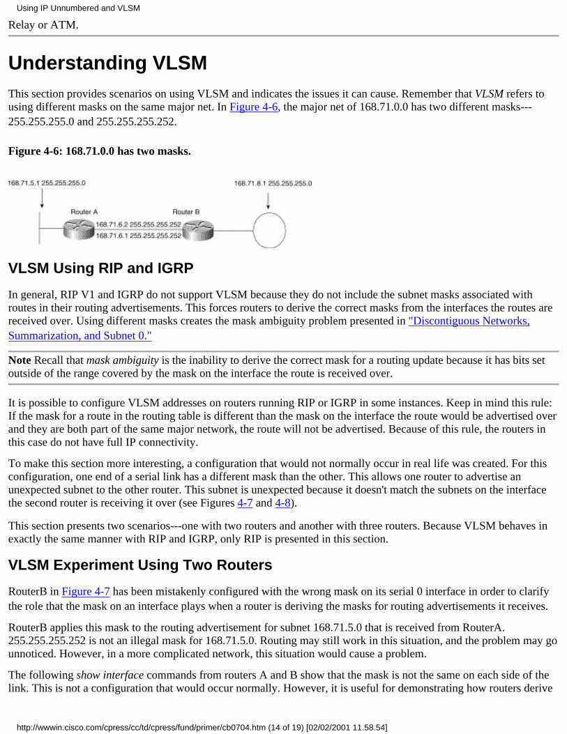
Relay or ATM.
Understanding VLSMThis section provides scenarios on using VLSM and indicates the issues it can cause. Remember that VLSM refers tousing different masks on the same major net. In Figure 4-6, the major net of 168.71.0.0 has two different masks---255.255.255.0 and 255.255.255.252.
Figure 4-6: 168.71.0.0 has two masks.
VLSM Using RIP and IGRP
In general, RIP V1 and IGRP do not support VLSM because they do not include the subnet masks associated withroutes in their routing advertisements. This forces routers to derive the correct masks from the interfaces the routes arereceived over. Using different masks creates the mask ambiguity problem presented in "Discontiguous Networks,Summarization, and Subnet 0."
Note Recall that mask ambiguity is the inability to derive the correct mask for a routing update because it has bits setoutside of the range covered by the mask on the interface the route is received over.
It is possible to configure VLSM addresses on routers running RIP or IGRP in some instances. Keep in mind this rule:If the mask for a route in the routing table is different than the mask on the interface the route would be advertised overand they are both part of the same major network, the route will not be advertised. Because of this rule, the routers inthis case do not have full IP connectivity.
To make this section more interesting, a configuration that would not normally occur in real life was created. For thisconfiguration, one end of a serial link has a different mask than the other. This allows one router to advertise anunexpected subnet to the other router. This subnet is unexpected because it doesn't match the subnets on the interfacethe second router is receiving it over (see Figures 4-7 and 4-8).
This section presents two scenarios---one with two routers and another with three routers. Because VLSM behaves inexactly the same manner with RIP and IGRP, only RIP is presented in this section.
VLSM Experiment Using Two Routers
RouterB in Figure 4-7 has been mistakenly configured with the wrong mask on its serial 0 interface in order to clarifythe role that the mask on an interface plays when a router is deriving the masks for routing advertisements it receives.
RouterB applies this mask to the routing advertisement for subnet 168.71.5.0 that is received from RouterA.255.255.255.252 is not an illegal mask for 168.71.5.0. Routing may still work in this situation, and the problem may gounnoticed. However, in a more complicated network, this situation would cause a problem.
The following show interface commands from routers A and B show that the mask is not the same on each side of thelink. This is not a configuration that would occur normally. However, it is useful for demonstrating how routers derive
Using IP Unnumbered and VLSM
http://wwwin.cisco.com/cpress/cc/td/cpress/fund/primer/cb0704.htm (14 of 19) [02/02/2001 11.58.54]

masks for network addresses and for indicating the problems that can occur when the derived mask is not appropriate.The primary problem in this situation is that incorrect subnet masks are associated with received route advertisements.
Figure 4-7: RouterB has the wrong mask on serial 0.
RouterA#show interface serial 0Serial0 is up, line protocol is up Hardware is HD64570 Internet address is 168.71.6.1 255.255.255.0RouterB#show interface serial 0Serial0 is up, line protocol is up Hardware is HD64570 Internet address is 168.71.6.2 255.255.255.252
In the following output of the show ip route command from routers A and B, you can see that each router believes168.71.5.0 has a different mask. In this scenario, the routers' masks will still be inconsistent, but connectivity will stillbe possible.
RouterA#show ip route 168.71.5.0Routing entry for 168.71.5.0 255.255.255.0 Known via "connected", distance 0, metric 0 (connected)RouterB#show ip route 168.71.5.0Routing entry for 168.71.5.0 255.255.255.252 Known via "rip", distance 120, metric 1
In the following output from RouterB pinging 168.71.5.1 you can see that routing is working for 168.71.5.1:
RouterB#ping 168.71.5.1Type escape sequence to abort.Sending 5, 100-byte ICMP Echos to 168.71.5.1, timeout is 2 seconds:!!!!!Success rate is 100 percent (5/5), round-trip min/avg/max = 4/4/8 msRouterB#
In this scenario, connectivity was still possible from one router to the other using the assigned IP addresses. However,routing would not work if RouterB received a packet for 168.71.5.10. RouterB could not forward this packet because alongest match lookup for 168.71.5.10 in the routing table would not match against the routing entry for 168.71.5.0255.255.255.252.
The .10 in the last octet of the IP address 168.71.5.10 has bits set that fall under the range of the mask for the last octetin the routing table entry: .252. This indicates that the host address 168.71.5.10 is not on the subnet covered by168.71.5.0 255.255.255.252.
See the section in "Hexadecimal and Binary Numbering and IP Addressing," on determining which subnet a hostaddress falls under if you need more information on this issue.
The following output of the show ip route 168.71.5.10 command from RouterB shows that RouterB doesn't have a
Using IP Unnumbered and VLSM
http://wwwin.cisco.com/cpress/cc/td/cpress/fund/primer/cb0704.htm (15 of 19) [02/02/2001 11.58.54]
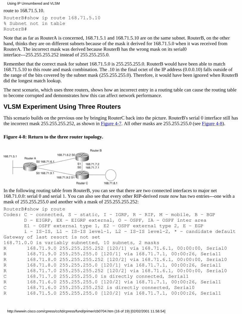
route to 168.71.5.10.
RouterB#show ip route 168.71.5.10% Subnet not in tableRouterB#
Note that as far as RouterA is concerned, 168.71.5.1 and 168.71.5.10 are on the same subnet. RouterB, on the otherhand, thinks they are on different subnets because of the mask it derived for 168.71.5.0 when it was received fromRouterA. The incorrect mask was derived because RouterB has the wrong mask on its serial0interface---255.255.255.252 instead of 255.255.255.0.
Remember that the correct mask for subnet 168.71.5.0 is 255.255.255.0. RouterB would have been able to match168.71.5.10 to this route and mask combination. The .10 in the final octet of the IP address (0.0.0.10) falls outside ofthe range of the bits covered by the subnet mask (255.255.255.0). Therefore, it would have been ignored when RouterBdid the longest match lookup.
The next scenario, which uses three routers, shows how an incorrect entry in a routing table can cause the routing tableto become corrupted and demonstrates how this can affect network performance.
VLSM Experiment Using Three Routers
This scenario builds on the previous one by bringing RouterC back into the picture. RouterB's serial 0 interface still hasthe incorrect mask 255.255.255.252, as shown in Figure 4-7. All other masks are 255.255.255.0 (see Figure 4-8).
Figure 4-8: Return to the three router topology.
In the following routing table from RouterB, you can see that there are two connected interfaces to major net168.71.0.0: serial 0 and serial 1. You can also see that every other RIP-derived route now has two entries---one with amask of 255.255.255.0 and another with a mask of 255.255.255.252:
RouterB#show ip routeCodes: C - connected, S - static, I - IGRP, R - RIP, M - mobile, B - BGP D - EIGRP, EX - EIGRP external, O - OSPF, IA - OSPF inter area E1 - OSPF external type 1, E2 - OSPF external type 2, E - EGP i - IS-IS, L1 - IS-IS level-1, L2 - IS-IS level-2, * - candidate defaultGateway of last resort is not set168.71.0.0 is variably subnetted, 10 subnets, 2 masksR 168.71.9.0 255.255.255.252 [120/1] via 168.71.6.1, 00:00:00, Serial0R 168.71.9.0 255.255.255.0 [120/1] via 168.71.7.1, 00:00:26, Serial1R 168.71.8.0 255.255.255.252 [120/2] via 168.71.6.1, 00:00:00, Serial0R 168.71.8.0 255.255.255.0 [120/1] via 168.71.7.1, 00:00:26, Serial1R 168.71.7.0 255.255.255.252 [120/2] via 168.71.6.1, 00:00:00, Serial0C 168.71.7.0 255.255.255.0 is directly connected, Serial1R 168.71.6.0 255.255.255.0 [120/2] via 168.71.7.1, 00:00:26, Serial1C 168.71.6.0 255.255.255.252 is directly connected, Serial0R 168.71.5.0 255.255.255.0 [120/2] via 168.71.7.1, 00:00:26, Serial1
Using IP Unnumbered and VLSM
http://wwwin.cisco.com/cpress/cc/td/cpress/fund/primer/cb0704.htm (16 of 19) [02/02/2001 11.58.54]

R 168.71.5.0 255.255.255.252 [120/1] via 168.71.6.1, 00:00:00, Serial0RouterB#
You can see that the entries for the following routing tables from routers A and C are as expected because they bothhave the correct masks on each interface:
RouterA#show ip routeCodes: C - connected, S - static, I - IGRP, R - RIP, M - mobile, B - BGP D - EIGRP, EX - EIGRP external, O - OSPF, IA - OSPF inter area E1 - OSPF external type 1, E2 - OSPF external type 2, E - EGP i - IS-IS, L1 - IS-IS level-1, L2 - IS-IS level-2, * - candidate defaultGateway of last resort is not set168.71.0.0 255.255.255.0 is subnetted, 5 subnetsC 168.71.9.0 is directly connected, Serial1R 168.71.8.0 [120/1] via 168.71.9.2, 00:00:03, Serial1R 168.71.7.0 [120/1] via 168.71.9.2, 00:00:03, Serial1C 168.71.6.0 is directly connected, Serial0C 168.71.5.0 is directly connected, Ethernet0RouterA#RouterC#show ip routeCodes: C - connected, S - static, I - IGRP, R - RIP, M - mobile, B - BGP D - EIGRP, EX - EIGRP external, O - OSPF, IA - OSPF inter area E1 - OSPF external type 1, E2 - OSPF external type 2, E - EGP i - IS-IS, L1 - IS-IS level-1, L2 - IS-IS level-2, * - candidate defaultGateway of last resort is not set168.71.0.0 255.255.255.0 is subnetted, 5 subnetsC 168.71.9.0 is directly connected, Serial1C 168.71.8.0 is directly connected, TokenRing0C 168.71.7.0 is directly connected, Serial0R 168.71.6.0 [120/1] via 168.71.9.1, 00:00:07, Serial1R 168.71.5.0 [120/1] via 168.71.9.1, 00:00:07, Serial1RouterC#
In this example, if RouterB attempted to ping 168.71.8.1, it would do a longest match lookup and determine that itsroute to 168.71.8.0 255.255.255.252 via RouterA was the best path to reach this IP address.
The following output of the show ip route 168.71.8.1 command from RouterB shows that RouterB believes its bestroute to 168.71.8.0 is via RouterA, not RouterC.
RouterB#show ip route 168.71.8.1Routing entry for 168.71.8.0 255.255.255.252 Known via "rip", distance 120, metric 2 Redistributing via rip Last update from 168.71.6.1 on Serial0, 00:00:24 ago Routing Descriptor Blocks: * 168.71.6.1, from 168.71.6.1, 00:00:24 ago, via Serial0 Route metric is 2, traffic share count is 1RouterB#
RouterB sends the pings to 168.71.8.1 via RouterA. The IP address of the outbound interface is used by default when arouter sends a ping, so the IP source addresses in this scenario are all 168.71.6.2, not 168.71.7.2---the IP address onRouterB closest to RouterC. RouterA, which has the correct route and mask for 168.71.8.0, forwards the pings via itsserial 1 interface to RouterC. RouterC sends its replies via its serial 0 interface to RouterB, resulting in what iscommonly called asymmetric routing---two hosts using different paths when sending IP packets to each other.
Using IP Unnumbered and VLSM
http://wwwin.cisco.com/cpress/cc/td/cpress/fund/primer/cb0704.htm (17 of 19) [02/02/2001 11.58.54]

These last two sections have further explained the function of deriving masks for routes from the interfaces the routesare learned over. They have also shown some interesting situations that can arise when a misconfiguration occurs.
The following section explains what happens when VLSM is properly configured and routing advertisements areblocked entirely.
Correctly Configuring VLSM Blocked Routes
A blocked route is a route that is not advertised by a router because it doesn't fit the mask of the outbound interface. Inthe example in Figure 4-9, the masks and addresses on RouterA's serial 0 have been changed. The new mask is255.255.255.252. Both routers now have the same mask on this link.
Figure 4-9: VLSM is configured correctly.
In the following output of the show interface command from routers A and B, you can see that both ends of the linkhave the same mask:
RouterA#show interface serial 0Serial0 is up, line protocol is up Hardware is HD64570 Internet address is 168.71.6.1 255.255.255.252 MTU 1500 bytes, BW 128 Kbit, DLY 20000 usec, rely 255/255, load 1/255RouterB#show interface serial 0Serial0 is up, line protocol is up Hardware is HD64570 Internet address is 168.71.6.2 255.255.255.252 MTU 1500 bytes, BW 128 Kbit, DLY 20000 usec, rely 255/255, load 1/255
In the following routing tables from routers A and B, you can see that there are no RIP-derived routes:
RouterA#show ip routeCodes: C - connected, S - static, I - IGRP, R - RIP, M - mobile, B - BGP D - EIGRP, EX - EIGRP external, O - OSPF, IA - OSPF inter area E1 - OSPF external type 1, E2 - OSPF external type 2, E - EGP i - IS-IS, L1 - IS-IS level-1, L2 - IS-IS level-2, * - candidate defaultGateway of last resort is not set 168.71.0.0 is variably subnetted, 2 subnets, 2 masksC 168.71.6.0 255.255.255.252 is directly connected, Serial0C 168.71.5.0 255.255.255.0 is directly connected, Ethernet0RouterA#RouterB#show ip routeCodes: C - connected, S - static, I - IGRP, R - RIP, M - mobile, B - BGP D - EIGRP, EX - EIGRP external, O - OSPF, IA - OSPF inter area E1 - OSPF external type 1, E2 - OSPF external type 2, E - EGP
Using IP Unnumbered and VLSM
http://wwwin.cisco.com/cpress/cc/td/cpress/fund/primer/cb0704.htm (18 of 19) [02/02/2001 11.58.54]

i - IS-IS, L1 - IS-IS level-1, L2 - IS-IS level-2, * - candidate defaultGateway of last resort is not set168.71.0.0 is variably subnetted, 2 subnets, 2 masksC 168.71.8.0 255.255.255.0 is directly connected, TokenRing0C 168.71.6.0 255.255.255.252 is directly connected, Serial0RouterB#
In this example, 255.255.255.252 and 255.255.255.0 are both legitimate masks for 168.71.5.0, 168.71.8.0, and168.71.6.0. However, the routers will still not advertise their local LAN interface subnets to each other. It is notsufficient for a mask on an outward bound interface to be legitimate for a particular route. It must be an exact match forthe mask the router has stored in its table.
The following output from the debug ip rip command on routers A and B shows the RIP process suppressing theupdates because they are empty:
RouterA#debug ip ripOct 30 23:21:46: RIP: sending update to 255.255.255.255 via Serial0 (168.71.6.1) - suppressing null updateRouterB# debug ip ripOct 30 23:21:46: RIP: sending update to 255.255.255.255 via Serial0 (168.71.6.2) - suppressing null update
Proper configuration of VLSM results in routers failing to send any routes in their advertisements, which leads to atotal loss of connectivity in many cases.
VLSM Summary
This section has shown the reason RIP and IGRP do not support VLSM (no masks carried in advertisements) and themethod used for preventing its use at all (updates over interfaces in the same major net with different masks aresuppressed).
SummaryThis chapter has covered some of the basics behind using IP unnumbered and VLSM. The use of these functions withrouting protocols that don't support them, such as RIP V1 and IGRP, can have varying implications---from using thewrong route to forward packets to total connectivity loss.
The next chapter discusses default routing (how hosts and routers route packets off of their local subnet) and some ofthe complexities surrounding this issue. It provides scenarios based on working and improper configurations.
Posted: Wed Mar 3 10:01:12 PST 1999Copyright 1989-1999©Cisco Systems Inc.Copyright © 1997 Macmillan Publishing USA, a Simon & Schuster Company
Using IP Unnumbered and VLSM
http://wwwin.cisco.com/cpress/cc/td/cpress/fund/primer/cb0704.htm (19 of 19) [02/02/2001 11.58.54]
Table of Contents
Default Routing
Introduction to Default RoutingGateway of Last Resort
Gateway of Last Resort for a Non-Local DomainGateway of Last Resort Fails for a Local DomainGateway of Last Resort Still Works When Links FailUsing IP ClasslessIn Review
Using Default and Static Routes in Complicated NetworksUsing Static RoutesDealing with Too Much Default Routing InformationFixing a Default Gateway LoopThe 0.0.0.0 Default Route
RIP and 0.0.0.0Using 0.0.0.0 with IGRPWhat to Do Instead of Using 0.0.0.0 with IGRP
Using End Systems with Multiple Local GatewaysICMP Router Discovery Protocol (IRDP) RFC 1256End Systems Using RIPCisco's Hot Standby Router Protocol (HSRP)
Using Floating Static RoutesSummary
Default RoutingThis chapter discusses end systems' use of a single local gateway or multiple local gateways to reach devices on remotesubnets. Gateways are routers that forward IP packets from one network or subnetwork to another.
This chapter should not be taken as an exhaustive analysis of all possible ways of solving the problem of reaching devices onremote subnets. An entire book could be written on this issue. I hope this explanation of the fundamental problem and thesolutions offered will enable you to apply the solutions where appropriate. When the solutions presented here are notappropriate, the information in this chapter will improve your ability to articulate your particular situation when requestingdesign assistance.
Before proceeding any further, an initial explanation of some terms is necessary.
Introduction to Default RoutingThe gateway of last resort is the term applied to a routing entry in the Cisco routing table that the router forwards packets towhen it lacks a more specific route. The gateway of last resort can be learned from a route provided by another router that istagged as candidate default by the advertising router. The ip default-network command is one way to make a router tag a routeas a gateway of last resort.
The ip default-network xxx.xxx.xxx.xxx command causes a router to treat xxx.xxx.xxx.xxx as a gateway of last resort. A routercan have multiple IP default networks entered.
Default Routing
http://wwwin.cisco.com/cpress/cc/td/cpress/fund/primer/cb0705.htm (1 of 29) [02/02/2001 11.59.46]

The ip default-gateway command is used with routers that have IP routing disabled. It gives them an address to which they canforward packets whose destination IP addresses are not in their address space. 2500s in boot ROM mode are a good example ofthis situation. The version of Cisco IOS that runs from the 2500 boot ROM doesn't understand the default-network command.
Note To upgrade a 2500 with a single flash memory partition, you must reconfigure the configuration registers so that therouter comes up in boot ROM mode the next time it is rebooted.
The local domain refers to networks a router has local knowledge (context) of because it has a direct connection to them.Using secondary addresses is a way to use the same interface on a router to connect to two or more subnets. A secondaryaddress is sometimes used when all host addresses from one subnet have been assigned and there are still more hosts on thephysical network that need an IP address.
If a LAN segment has a subnetted address space of 168.71.2.16 with a mask of 255.255.255.240, only 14 host addresses areavailable. If more than 14 hosts are attached to the network, another IP address space (subnet) is required. In this situation,hosts in different subnets attached to the same LAN must use the router to forward packets to one another.
Gateway of Last ResortIn Figure 5-1, if RouterC did not have an explicit route to subnet 168.72.6.0 or the major network 168.72.0.0, it would need agateway of last resort to send packets to this subnet.
Figure 5-1: The link between RouterA and RouterB has a different major network than all other networks.
In the following routing table from RouterC, you can see that RouterC has installed a gateway of last resort network 10.0.0.0with a next hop of 168.71.9.1. You can also see that there is no route to 168.72.6.0 or 168.72.0.0.
RouterC#show ip routeCodes: C - connected, S - static, I - IGRP, R - RIP, M - mobile, B - BGP D - EIGRP, EX - EIGRP external, O - OSPF, IA - OSPF inter area E1 - OSPF external type 1, E2 - OSPF external type 2, E - EGP i - IS-IS, L1 - IS-IS level-1, L2 - IS-IS level-2, * - candidate defaultGateway of last resort is 168.71.9.1 to network 10.0.0.0I* 10.0.0.0 [100/82125] via 168.71.9.1, 00:01:06, Serial1168.71.0.0 255.255.255.0 is subnetted, 5 subnetsC 168.71.9.0 is directly connected, Serial1C 168.71.8.0 is directly connected, TokenRing0C 168.71.7.0 is directly connected, Serial0I 168.71.5.0 [100/10002001] via 168.71.9.1, 00:01:07, Serial1RouterC#
The gateway of last resort is being advertised by RouterA as a candidate default route. It is up to the router receiving acandidate default route to determine whether it should install it as the gateway of last resort. In this scenario, having RouterAadvertise 10.0.0.0 as the candidate default route also caused RouterB to send a route to RouterC for 10.0.0.0 that RouterBflagged as a candidate default route.
Figure 5-1 shows that as far as RouterC is concerned, the link between RouterC and RouterA is the best path for reaching10.0.0.0 because RouterB increases the metric for 10.0.0.0 when advertising it to RouterC. RouterA's metric is smaller than
Default Routing
http://wwwin.cisco.com/cpress/cc/td/cpress/fund/primer/cb0705.htm (2 of 29) [02/02/2001 11.59.46]

RouterB's. Interestingly enough, as far as reaching 168.71.6.0 is concerned, both of RouterC's physical paths---via RouterA orRouterB---could be of equal cost if all links in the network were the same delay and bandwidth. However, because thisscenario relies on using the gateway of last resort to 10.0.0.0 to reach 168.71.6.0, only one path is used even if they are equalcost in theory.
The following configuration from RouterA shows how to enable this function:
RouterA!interface ethernet0ip address 168.71.5.1 255.255.255.0ip address 171.68.207.164 255.255.128 secondary!interface serial0ip address 168.72.6.1 255.255.255.0bandwidth 128!interface serial1ip address 168.71.9.1 255.255.255.0bandwidth 128!router igrp 109redistribute staticnetwork 168.71.0.0default-metric 128 2000 255 1 1500!ip default-network 10.0.0.0ip route 10.0.0.0 255.0.0.0 171.68.207.129!
The following is a step-by-step explanation of enabling a router to advertise a gateway of last resort. The steps do not have tobe performed in this exact order, but all steps must be completed.
1. Enter the appropriate ip default-network command. In this case, network 10.0.0.0 is used.
2. Interestingly, this network does not have to actually exist anywhere in the network. Because IP packets are forwardedon a hop-by-hop basis, it is necessary only to convince a router to send a packet to the next hop to ensure that the packetis making forward progress to its destination. What this command is doing is telling other routers that somewhere thereis a router advertising 10.0.0.0 and that the router knows how to reach every other network in the world. Therefore, apacket forwarded in the general direction of this router is on its way to reaching its ultimate destination. This conceptwas introduced in "Discontiguous Networks, Summarization, and Subnet 0," in the section on using summarization as atool.
3. Configure a next hop address to reach the default network. In this case, a host in the secondary address space onEthernet0 (171.68.207.129) is used. This is a static (manually configured) route.
4. Enable the redistribute static command for the routing protocol in use. In this case, IGRP is being used. If you fail toenter this command, the static route is not advertised.
5. Configure a default metric. If you fail to do so, the router uses the unreachable metric (infinity) when advertising thisroute, which prevents the route from being accepted by other routers.
6. The default metric command takes the following form: bandwidth, delay, reliability, load, and MTU. Review thesection on metrics in "Routing Metrics and Distances," for more information. Remember that by default only bandwidthand delay are used by IGRP. The delay in a route is cumulative, and the minimum bandwidth is used for all links in thepath.
Default Routing
http://wwwin.cisco.com/cpress/cc/td/cpress/fund/primer/cb0705.htm (3 of 29) [02/02/2001 11.59.46]

Gateway of Last Resort for a Non-Local Domain
The following scenario shows that RouterC uses the gateway of last resort to reach a subnet it has no explicit knowledge of.Remember that a non-local domain is a major network address space that the router has no physical connection to. Refer toFigure 5-1 for the network topology used in this scenario.
In the following output of the show ip route command from RouterC, you can see that RouterC does not have a subnet route to168.72.6.0 or a summarized route to the major net 168.72.0.0:
RouterC#show ip route 168.72.6.0% Network not in tableRouterC#show ip route 168.72.0.0% Network not in tableRouterC#
In the following output from RouterC, you can see that RouterC can ping 168.72.6.1:
RouterC#ping 168.72.6.1Type escape sequence to abort.Sending 5, 100-byte ICMP Echos to 168.72.6.1, timeout is 2 seconds:!!!!!Success rate is 100 percent (5/5), round-trip min/avg/max = 16/16/16 msRouterC#
Gateway of Last Resort Fails for a Local Domain
In the scenario shown in Figure 5-2, the link between RouterA and RouterB is now part of the 168.71.0.0 domain that all othernetworks are using. However, the mask has been changed to 255.255.255.252. This was done to prevent RouterA and RouterBfrom advertising the 168.71.6.0 subnet. See "Using IP Unnumbered and VLSM," for more information on VLSM.
Figure 5-2: The link between RouterA and RouterB has the same major network but a different mask.
In the following routing table from RouterC, you can see that RouterC does not have a route to 168.71.6.0 or a summarizedroute to 168.71.0.0:
RouterC#show ip route 168.71.6.0% Subnet not in tableRouterC#show ip route 168.71.0.0Routing entry for 168.71.0.0 255.255.255.0, 4 known subnets Attached (3 connections) Redistributing via igrp 109C 168.71.9.0 is directly connected, Serial1C 168.71.8.0 is directly connected, TokenRing0C 168.71.7.0 is directly connected, Serial0I 168.71.5.0 [100/10002001] via 168.71.9.1, 00:00:36, Serial1
Note An access list has been applied to the end of this debug command, which limits the output of the command to packetsthat match the access list. Adding the access list affects only the actual debug messages. It is a good idea to add an access list
Default Routing
http://wwwin.cisco.com/cpress/cc/td/cpress/fund/primer/cb0705.htm (4 of 29) [02/02/2001 11.59.46]

whenever a router with lots of IP traffic is being used to debug a problem related to the forwarding of IP packets. Rememberthat debug commands work only for IP packets that are being process switched. Ping packets generated by a router are alwaysprocess switched, so adding the access list to the debug command will always work in situations similar to this one.
Note To determine whether access list debugging is available for a certain debug command, type a question mark (?) at the endof the command. If access list debugging is available, the prompt indicates that you can enter an access list number.
In the following output of the debug ip packet command from RouterC, you can see that RouterC doesn't have a route to usefor packets destined to 168.71.6.1:
RouterC#debug ip packet 103IP packet debugging is on for access list 103RouterC#ping 168.71.6.1Type escape sequence to abort.Sending 5, 100-byte ICMP Echos to 168.71.6.1, timeout is 2 seconds:Oct 8 21:30:32: IP: s=168.71.7.1 (local), d=168.71.6.1, len 100, unroutable.Oct 8 21:30:34: IP: s=168.71.7.1 (local), d=168.71.6.1, len 100, unroutable.Oct 8 21:30:36: IP: s=168.71.7.1 (local), d=168.71.6.1, len 100, unroutable.Oct 8 21:30:38: IP: s=168.71.7.1 (local), d=168.71.6.1, len 100, unroutable.Oct 8 21:30:40: IP: s=168.71.7.1 (local), d=168.71.6.1, len 100, unroutable.Success rate is 0 percent (0/5)RouterC#
The following is the content of access list 103:
RouterC#show access-lists 103Extended IP access list 103 permit ip any 168.71.6.0 0.0.0.255 (5 matches)RouterC#
In the following routing table from RouterC, you can see that RouterC has a gateway of last resort installed. It was ignoredbecause routers do not use a gateway of last resort for addresses that are part of its local domain---a major network it hasconnections to.
RouterC#show ip routeCodes: C - connected, S - static, I - IGRP, R - RIP, M - mobile, B - BGP D - EIGRP, EX - EIGRP external, O - OSPF, IA - OSPF inter area E1 - OSPF external type 1, E2 - OSPF external type 2, E - EGP i - IS-IS, L1 - IS-IS level-1, L2 - IS-IS level-2, * - candidate defaultGateway of last resort is 168.71.9.1 to network 10.0.0.0I* 10.0.0.0 [100/82125] via 168.71.9.1, 00:00:29, Serial1168.71.0.0 255.255.255.0 is subnetted, 4 subnetsC 168.71.9.0 is directly connected, Serial1C 168.71.8.0 is directly connected, TokenRing0C 168.71.7.0 is directly connected, Serial0I 168.71.5.0 [100/10002001] via 168.71.9.1, 00:00:29, Serial1RouterC#
The solution to this problem is to enter a static route for the summarized major net that points to the gateway of last resort. Inthis case, the fact that 10.0.0.0 is tagged as a gateway of last resort is not relevant. This scenario would still work if RouterAadvertised 10.0.0.0 without also flagging it as a candidate default route (capable of being used as a gateway of last resort). Thefollowing configuration from RouterC shows how to add the static route that will point to the gateway of last resort:
RouterC!interface tokenring0ip address 168.71.8.1 255.255.255.0!interface serial0
Default Routing
http://wwwin.cisco.com/cpress/cc/td/cpress/fund/primer/cb0705.htm (5 of 29) [02/02/2001 11.59.46]

ip address 168.71.7.1 255.255.255.0bandwidth 64!interface serial1ip address 168.71.9.2 255.255.255.0bandwidth 128!router igrp 109network 168.71.0.0!ip route 168.71.0.0 255.255.0.0 10.0.0.0!
The following routing table from RouterC shows that RouterC has installed the static route for 168.71.0.0 via 10.0.0.0:
RouterC#show ip routeCodes: C - connected, S - static, I - IGRP, R - RIP, M - mobile, B - BGP D - EIGRP, EX - EIGRP external, O - OSPF, IA - OSPF inter area E1 - OSPF external type 1, E2 - OSPF external type 2, E - EGP i - IS-IS, L1 - IS-IS level-1, L2 - IS-IS level-2, * - candidate defaultGateway of last resort is 168.71.9.1 to network 10.0.0.0I* 10.0.0.0 [100/82125] via 168.71.9.1, 00:00:05, Serial1168.71.0.0 is variably subnetted, 5 subnets, 2 masksC 168.71.9.0 255.255.255.0 is directly connected, Serial1C 168.71.8.0 255.255.255.0 is directly connected, TokenRing0C 168.71.7.0 255.255.255.0 is directly connected, Serial0I 168.71.5.0 255.255.255.0 [100/10002001] via 168.71.9.1, 00:00:05, Serial1S 168.71.0.0 255.255.0.0 [1/0] via 10.0.0.0RouterC#
The following output from the show ip route command on RouterC shows that RouterC now has a route it can use to thesubnet 168.71.6.0. When queried about its knowledge of a route, it does a longest match lookup in its routing table. In thiscase, the longest match is to the major net itself.
RouterC#show ip route 168.71.6.1Routing entry for 168.71.0.0 255.255.0.0 Known via "static", distance 1, metric 0 Routing Descriptor Blocks: * 10.0.0.0 Route metric is 0, traffic share count is 1RouterC#
Note To ensure that you receive the output for the full destination subnet, use the full IP address of a host on the destinationsubnet when using the show ip route command. You might find that a subnet exists in the routing table that you did not knowexisted. It is not uncommon to have a routing table with thousands of entries in it. It can be easy to miss a subnet when doing avisual scan. Using the show ip route command to scan the table is much easier and less prone to failure.
In the following output from RouterC, you can see that RouterC can now ping 168.71.6.1:
RouterC#ping 168.71.6.1Type escape sequence to abort.Sending 5, 100-byte ICMP Echos to 168.71.6.1, timeout is 2 seconds:!!!!!Success rate is 100 percent (5/5), round-trip min/avg/max = 16/17/20 msRouterC#
Default Routing
http://wwwin.cisco.com/cpress/cc/td/cpress/fund/primer/cb0705.htm (6 of 29) [02/02/2001 11.59.46]

Gateway of Last Resort Still Works When Links Fail
In this scenario (shown in Figure 5-3 and the output that follows), the link between RouterA and RouterC has failed. RouterChas converged on the path via RouterB for its route to the gateway of last resort network (10.0.0.0). 10.0.0.0 is now known viathe next hop address of 168.71.7.2 (RouterB's serial 1). Because RouterC's local domain default route (168.71.0.0) is a staticroute to network 10.0.0.0, it works on the new path for 10.0.0.0 via RouterB as well.
Figure 5-3: The link between RouterA and RouterC has gone down.
RouterC#show ip routeCodes: C - connected, S - static, I - IGRP, R - RIP, M - mobile, B - BGP D - EIGRP, EX - EIGRP external, O - OSPF, IA - OSPF inter area E1 - OSPF external type 1, E2 - OSPF external type 2, E - EGP i - IS-IS, L1 - IS-IS level-1, L2 - IS-IS level-2, * - candidate defaultGateway of last resort is 168.71.7.2 to network 10.0.0.0I* 10.0.0.0 [100/84125] via 168.71.7.2, 00:01:07, Serial0I 171.68.0.0 [100/10004001] via 168.71.7.2, 00:01:07, Serial0 168.71.0.0 is variably subnetted, 3 subnets, 2 masksC 168.71.8.0 255.255.255.0 is directly connected, TokenRing0C 168.71.7.0 255.255.255.0 is directly connected, Serial0S 168.71.0.0 255.255.0.0 [1/0] via 10.0.0.0RouterC#
Using IP Classless
A simpler method for forcing a router to use a gateway of last resort for remote subnets that are part of the local domain is toconfigure the ip classless command. This command causes the router to ignore all aspects of address classes when makingrouting decisions. The following excerpt from RouterC's configuration shows how ip classless has been configured.
!ip classless!
Note ip classless is a global command. It affects all routing protocols in the router. It should be used with caution. A thoroughdiscussion of all of the implications of using this command is beyond the scope of this book. Please refer to your Cisco IOSdocumentation for more information.
Note The ip classless command will be on by default in Cisco IOS Version 11.3. See bug number CSCdj21662 on CCO(http://www.cisco.com) for more information.
In the following output of the show ip route command on RouterC, you can see that, once again, RouterC has no knowledge ofhow it should route packets for 168.71.6.0:
RouterC#show ip route 168.71.6.0% Subnet not in tableRouterC#
In the following output from RouterC pinging 168.71.6.1, you can see that the ping is successful:
Default Routing
http://wwwin.cisco.com/cpress/cc/td/cpress/fund/primer/cb0705.htm (7 of 29) [02/02/2001 11.59.46]

RouterC#ping 168.71.6.1Type escape sequence to abort.Sending 5, 100-byte ICMP Echos to 168.71.6.1, timeout is 2 seconds:!!!!!Success rate is 100 percent (5/5), round-trip min/avg/max = 16/17/20 msRouterC#
As you can see, RouterC can ping a local domain subnet that it has no knowledge of even though the local domain defaultroute pointing to 10.0.0.0 (ip route 168.71.0.0 255.255.0.0 10.0.0.0) has not been configured. Remember that this was arequired configuration parameter before the ip classless command was configured.
In Review
This section provides a quick review of the material just presented. The following section presents a scenario in which animproper use of static routes and gateways of last resort can cause connectivity failures. Figure 5-4 shows the network diagramthat will be used for this scenario.
Figure 5-4: A more complicated network configuration is required to make this scenario work properly.
Two types of IP network addresses are under consideration in this section. They are as follows:
Non-local domain addresses (a major network address that the router does not have a physical connection to)---In Figure5-4, RouterB does not have an explicit route to 168.72.5.0. However, it does have a gateway of last resort of 10.0.0.0.This gateway of last resort is created with a static route to 10.0.0.0 that points at 168.71.6.1 and configures the ipdefault-network 10.0.0.0 command. This route is sufficient for RouterB to forward packets to 167.72.5.0 becauseRouterB has no local context for 168.72.0.0 (it is not a local domain).
●
Local domain addresses (a major network address that the router does have a physical connection to)--- RouterA musthave either an explicit route back to 168.71.8.0 or a static route pointing to 168.71.8.0 with a next hop of 168.71.6.3. Agateway of last resort will not allow RouterA to reach 168.71.8.0 because RouterA is connected to the major net168.71.0.0. This connection makes 168.71.8.0 part of RouterA's local domain. Routers expect to have explicit routes forall subnets in their local domains. It is possible to get around this by installing a static route to the major network alone.However, this can lead to problems when configured improperly.
●
Using Default and Static Routes in Complicated NetworksIn this section, several scenarios are presented using static routes and gateways of last resort. These concepts are some of themost difficult for those new to the nuances of IP routing to understand. To truly understand routing, you must have a solidgrasp on the fundamentals of local domains versus non-local domains, gateways of last resort, summarized routes, andredistribution of static routes and default metrics.
Default Routing
http://wwwin.cisco.com/cpress/cc/td/cpress/fund/primer/cb0705.htm (8 of 29) [02/02/2001 11.59.46]
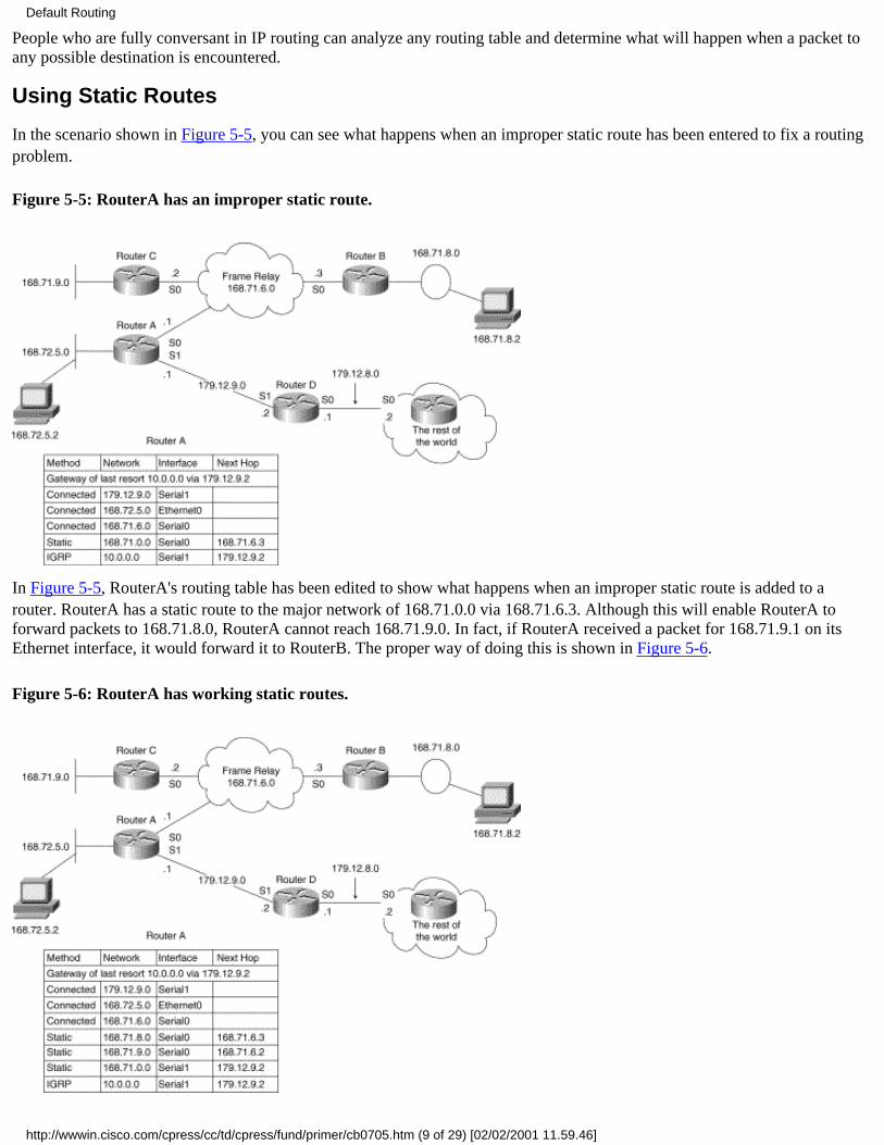
People who are fully conversant in IP routing can analyze any routing table and determine what will happen when a packet toany possible destination is encountered.
Using Static Routes
In the scenario shown in Figure 5-5, you can see what happens when an improper static route has been entered to fix a routingproblem.
Figure 5-5: RouterA has an improper static route.
In Figure 5-5, RouterA's routing table has been edited to show what happens when an improper static route is added to arouter. RouterA has a static route to the major network of 168.71.0.0 via 168.71.6.3. Although this will enable RouterA toforward packets to 168.71.8.0, RouterA cannot reach 168.71.9.0. In fact, if RouterA received a packet for 168.71.9.1 on itsEthernet interface, it would forward it to RouterB. The proper way of doing this is shown in Figure 5-6.
Figure 5-6: RouterA has working static routes.
Default Routing
http://wwwin.cisco.com/cpress/cc/td/cpress/fund/primer/cb0705.htm (9 of 29) [02/02/2001 11.59.46]

In Figure 5-6, the routing table has been fixed to allow full connectivity to the subnets shown. RouterA now has access to alllocal subnets of 168.71.0.0. It also has access to a gateway of last resort and a pointer via the summarized route that extendsfrom 168.71.0.0 via 179.12.9.2 to other unknown subnets of 168.71.0.0 that can be found somewhere in the rest of the world.
In Figure 5-7, the routing table has been changed to show what would happen if IGRP were used in the local domain to allowfull connectivity to the subnets shown and to allow static routes to all other subnets of 168.71.0.0 and other non-local domains.It is easier to use a dynamic protocol than static routes because they are easier to maintain.
Figure 5-7: IGRP has been used for some routes.
RouterA now has access to all local subnets of 168.71.0.0. RouterA also has a gateway of last resort and a pointer via thesummarized route that extends from 168.71.0.0 via 179.12.9.2 to other unknown subnets of 168.71.0.0.
Dealing with Too Much Default Routing Information
One of the problems designers of IP networks face is too much default information. By using a route---in this scenario,10.0.0.0---as both a gateway of last resort for non-local domain routes and a route for unknown subnets of the local domain,packets for networks that do not exist will end up at the router that is advertising this route.
This router can forward the packets to its own gateway of last resort---assuming it has one---or drop the packet as unroutable.The problem with dropping the packet is that the router may want to send an ICMP host or network unreachable message foreach unroutable packet. This can cause significant overhead if several network users are creating packets for routes that do notexist. That is why Cisco routers send only one ICMP host unreachable message back to the original host for each group ofpackets that arrive within a short time period.
The following problems can lead to packets arriving for unreachable destinations:
Incorrectly typed IP addresses in connection attempts for applications, such as Telnet and FTP. Routers forward thesevia their default routes until their Time to Live (TTL) expires or a router drops them as unroutable.
●
Bookmarks in Web browsers for sites that no longer exist.●
Traffic to domain name servers (DNS) that no longer exist. DNS servers are specified by an IP address, not a name. Anychange in their IP address can affect the many users who have been using this address to resolve names.
●
In networks with thousands of users, these kinds of packets happen all of the time. One solution is to configure a route to thenull0 interface. This is like /dev/null in UNIX. It is a legitimate interface that accepts the packets and then throws them away.No ICMP host or network unreachable messages are sent for packets forwarded to null0.
Default Routing
http://wwwin.cisco.com/cpress/cc/td/cpress/fund/primer/cb0705.htm (10 of 29) [02/02/2001 11.59.46]

In the scenario shown in Figure 5-8, the routing policy for the network containing RouterA, RouterB, RouterC, and RouterDstates that no other routers can advertise dynamic routes into this network. This creates a problem because 168.71.29.0 existsoutside of this network, even though it is from the local domain address space of this network.
The situation shown in Figure 5-8 can happen when a branch of a company has been moved to another region and has to use athird-party network, such as the Internet, to reach the original corporate site. Ideally, the hosts on this network would havebeen readdressed, but sometimes connectivity must be provided because there is not enough time to readdress. This situation isresolved by configuring a redistributed static route to 168.71.29.0 in RouterD.
Figure 5-8: Using static routes and null0.
In Figure 5-8, RouterD has a redistributed static route to 168.71.29.0 pointing at 179.12.8.2. RouterA, RouterB, and RouterCwill use this route, which they learned via IGRP, to forward packets for hosts on 168.71.29.0 in RouterD's direction.
RouterD has a redistributed static route to 10.0.0.0 that points at 179.12.8.2. This route is also tagged as a candidate default.RouterA, RouterB, and RouterC use this route, which they learned via IGRP, to forward packets for hosts on subnets in othermajor network domains in RouterD's direction. All packets arriving at RouterD for subnets of 168.71.0.0 that RouterD doesn'tknow about are sent to null0. This is due to the static route of 168.71.0.0 255.255.0.0 null0 that RouterD has configured.
One consequence of using static routes is that routers forward packets toward the next hop router even when the physicalnetwork that the static route points to is not operational. In Figure 5-8, RouterD forwards packets for hosts on 168.71.29.0 tothe next hop of 179.12.8.2 even if the physical network that 168.71.29.0 is assigned to is down. As long as they have a route,these packets continue to be forwarded from router to router until they reach a router that has learned via a dynamic routingprotocol (not a static route) that subnet 168.71.29.0 is no longer reachable.
If all of the WAN links between RouterD and the router with 168.71.29.0 attached to it in Figure 5-8 were high-speedconnections, there would be little or no point in attempting to prevent these packets from being forwarded.
On the other hand, if the link between RouterD and the rest of the world were only 56Kbit and usually running at 95-99percent, it would be useful to prevent these unnecessary packets from flowing across the link. That way, other packets coulduse the extra bandwidth. However, as previously stated, the policy in this network indicates that no dynamic routes are allowedin from the rest of the world; therefore, nothing can be done. This is a common tradeoff network administrators have to faceevery day.
This scenario brings up an interesting issue. If a router receives a packet for a subnet it has a connection to and that connection
Default Routing
http://wwwin.cisco.com/cpress/cc/td/cpress/fund/primer/cb0705.htm (11 of 29) [02/02/2001 11.59.46]

is inactive, the router could forward the packet to a gateway of last resort or a local domain static route. In order for the routerto use the gateway of last resort, the subnet on the inactive interface must not be part of the router's local domain. If the subnetin question were part of the local domain, the router would forward the packet only if it had a valid local domain default routeconfigured.
Consider what would happen if the router with the inactive interface had the only connection to the LAN that 168.71.29.0 wasassigned to. The packets to hosts on 168.71.29.0 (which the router would be forwarding to its gateway of last resort or localdomain default route) would still be forwarded by every other router that they encountered with the same default routes untiltheir TTL values expired.
In other words, packets with no chance of reaching their destinations travel aimlessly around the network until they die. Tomake matters worse, if the inactive LAN happens to have a lot of popular Web servers or other IP hosts on it, thousands ofpackets could be roaming around the network wasting bandwidth.
A solution to this issue is to configure a static route to null0 for every subnet a router has an attachment to. This static routemust have an administrative distance greater than the distance value associated with any dynamic IP routing protocol thatmight provide a viable alternative route. In this scenario, the following command would fix the problem: ip route 168.71.29.0255.255.255.0 null0 200.
Fixing a Default Gateway Loop
In the scenario shown in Figure 5-9, a situation has been created in which two routers have installed a gateway of last resortthat points to the other router.
Figure 5-9: Broken gateway of last resort.
The network administrator placed the static route for the gateway of last resort in RouterA instead of RouterB, where itbelongs.
RouterA has the redistribute static command configured, as well as a default metric. This causes RouterA to advertise theroute for 10.0.0.0 to RouterB. This is not a violation of split horizon because RouterA did not actually learn about 10.0.0.0from RouterB. Having a static route pointing to another router and having a route learned from another router are not the samething.
In other words, if RouterB had dynamically advertised a route for 10.0.0.0 to RouterA and RouterA had advertised it back toRouterB, that would be a violation of split horizon. In this case, RouterA is telling RouterB about a route that RouterA actuallyuses RouterB to reach.
Because RouterB doesn't have the static route to 10.0.0.0 statically configured as it should have had, it installs the dynamicroute learned from RouterA with the next hop of 168.71.6.1 and tags it as the gateway of last resort.
Packets to unknown destinations that should go to the rest of the world now bounce between the two routers. The followingrouting table from RouterA shows that its gateway of last resort is pointing to RouterB:
RouterA#show ip routeCodes: C - connected, S - static, I - IGRP, R - RIP, M - mobile, B - BGP D - EIGRP, EX - EIGRP external, O - OSPF, IA - OSPF inter area E1 - OSPF external type 1, E2 - OSPF external type 2, E - EGP
Default Routing
http://wwwin.cisco.com/cpress/cc/td/cpress/fund/primer/cb0705.htm (12 of 29) [02/02/2001 11.59.46]
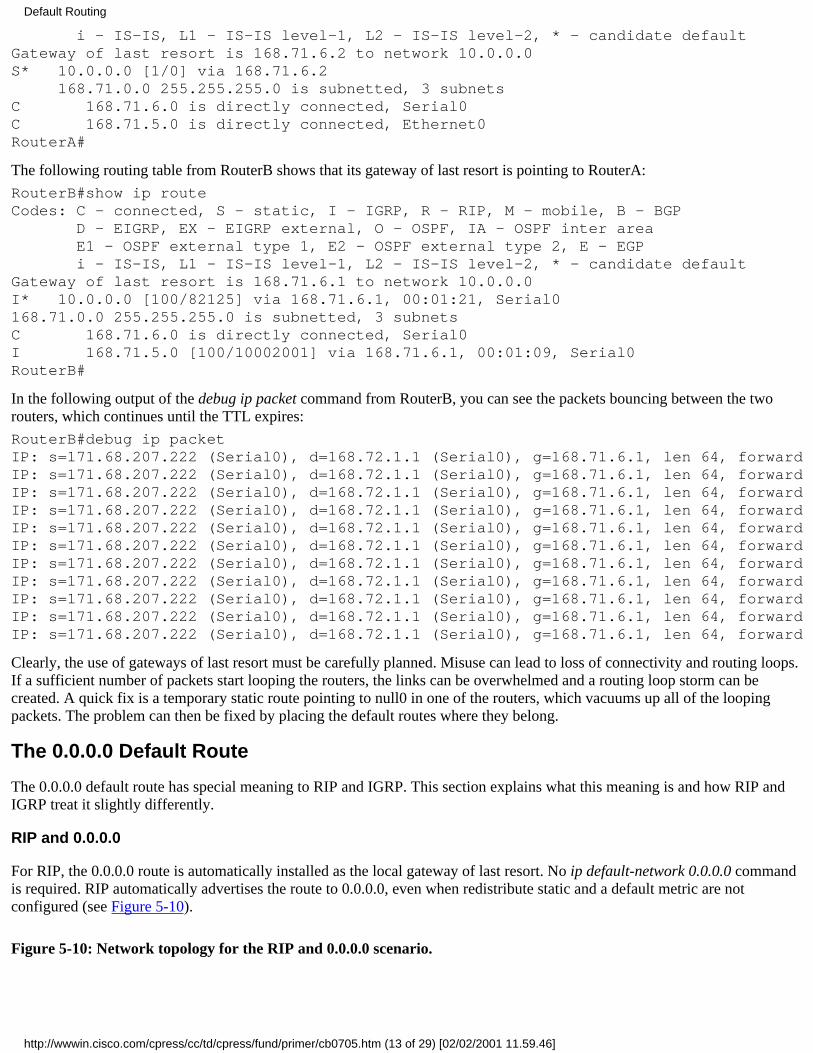
i - IS-IS, L1 - IS-IS level-1, L2 - IS-IS level-2, * - candidate defaultGateway of last resort is 168.71.6.2 to network 10.0.0.0S* 10.0.0.0 [1/0] via 168.71.6.2 168.71.0.0 255.255.255.0 is subnetted, 3 subnetsC 168.71.6.0 is directly connected, Serial0C 168.71.5.0 is directly connected, Ethernet0RouterA#
The following routing table from RouterB shows that its gateway of last resort is pointing to RouterA:
RouterB#show ip routeCodes: C - connected, S - static, I - IGRP, R - RIP, M - mobile, B - BGP D - EIGRP, EX - EIGRP external, O - OSPF, IA - OSPF inter area E1 - OSPF external type 1, E2 - OSPF external type 2, E - EGP i - IS-IS, L1 - IS-IS level-1, L2 - IS-IS level-2, * - candidate defaultGateway of last resort is 168.71.6.1 to network 10.0.0.0I* 10.0.0.0 [100/82125] via 168.71.6.1, 00:01:21, Serial0168.71.0.0 255.255.255.0 is subnetted, 3 subnetsC 168.71.6.0 is directly connected, Serial0I 168.71.5.0 [100/10002001] via 168.71.6.1, 00:01:09, Serial0RouterB#
In the following output of the debug ip packet command from RouterB, you can see the packets bouncing between the tworouters, which continues until the TTL expires:
RouterB#debug ip packetIP: s=171.68.207.222 (Serial0), d=168.72.1.1 (Serial0), g=168.71.6.1, len 64, forwardIP: s=171.68.207.222 (Serial0), d=168.72.1.1 (Serial0), g=168.71.6.1, len 64, forwardIP: s=171.68.207.222 (Serial0), d=168.72.1.1 (Serial0), g=168.71.6.1, len 64, forwardIP: s=171.68.207.222 (Serial0), d=168.72.1.1 (Serial0), g=168.71.6.1, len 64, forwardIP: s=171.68.207.222 (Serial0), d=168.72.1.1 (Serial0), g=168.71.6.1, len 64, forwardIP: s=171.68.207.222 (Serial0), d=168.72.1.1 (Serial0), g=168.71.6.1, len 64, forwardIP: s=171.68.207.222 (Serial0), d=168.72.1.1 (Serial0), g=168.71.6.1, len 64, forwardIP: s=171.68.207.222 (Serial0), d=168.72.1.1 (Serial0), g=168.71.6.1, len 64, forwardIP: s=171.68.207.222 (Serial0), d=168.72.1.1 (Serial0), g=168.71.6.1, len 64, forwardIP: s=171.68.207.222 (Serial0), d=168.72.1.1 (Serial0), g=168.71.6.1, len 64, forwardIP: s=171.68.207.222 (Serial0), d=168.72.1.1 (Serial0), g=168.71.6.1, len 64, forward
Clearly, the use of gateways of last resort must be carefully planned. Misuse can lead to loss of connectivity and routing loops.If a sufficient number of packets start looping the routers, the links can be overwhelmed and a routing loop storm can becreated. A quick fix is a temporary static route pointing to null0 in one of the routers, which vacuums up all of the loopingpackets. The problem can then be fixed by placing the default routes where they belong.
The 0.0.0.0 Default Route
The 0.0.0.0 default route has special meaning to RIP and IGRP. This section explains what this meaning is and how RIP andIGRP treat it slightly differently.
RIP and 0.0.0.0
For RIP, the 0.0.0.0 route is automatically installed as the local gateway of last resort. No ip default-network 0.0.0.0 commandis required. RIP automatically advertises the route to 0.0.0.0, even when redistribute static and a default metric are notconfigured (see Figure 5-10).
Figure 5-10: Network topology for the RIP and 0.0.0.0 scenario.
Default Routing
http://wwwin.cisco.com/cpress/cc/td/cpress/fund/primer/cb0705.htm (13 of 29) [02/02/2001 11.59.46]

The following routing table from RouterC in Figure 5-10 shows that RouterA is advertising a route to 0.0.0.0. It appears thatRouterA is the origin of this route, as well as RouterC's next hop, because it has a metric of 1.
RouterC#show ip routeCodes: C - connected, S - static, I - IGRP, R - RIP, M - mobile, B - BGP D - EIGRP, EX - EIGRP external, O - OSPF, IA - OSPF inter area E1 - OSPF external type 1, E2 - OSPF external type 2, E - EGP i - IS-IS, L1 - IS-IS level-1, L2 - IS-IS level-2, * - candidate defaultGateway of last resort is 168.71.9.1 to network 0.0.0.0 168.71.0.0 255.255.255.0 is subnetted, 5 subnetsC 168.71.9.0 is directly connected, Serial1C 168.71.8.0 is directly connected, TokenRing0C 168.71.7.0 is directly connected, Serial0R 168.71.6.0 [120/1] via 168.71.9.1, 00:00:10, Serial1 [120/1] via 168.71.7.2, 00:00:04, Serial0R 168.71.5.0 [120/1] via 168.71.9.1, 00:00:10, Serial1R* 0.0.0.0 0.0.0.0 [120/1] via 168.71.9.1, 00:00:10, Serial1RouterC#
The following partial configuration from RouterA shows how the route to 0.0.0.0 was created. In this case, null0 was used asthe ultimate destination. RouterB and RouterC used 0.0.0.0 as their gateway of last resort and sent all packets for unknownnon-local domain networks to RouterA.
Any packets for non-local domain networks arriving at RouterA that RouterA doesn't have a route for are sent to null0:
!hostname RouterA!router igrp rippassive-interface Ethernet0network 168.71.0.0!ip route 0.0.0.0 0.0.0.0 null0!
Notice that it was not necessary to configure redistribute static or a default metric. The metric is assumed to be that of aconnected route.
In the following output of the debug ip rip command from RouterA, you can see RouterA advertising 0.0.0.0 with a metric of1:
RouterA#debug ip ripRIP: sending update to 255.255.255.255 via Serial0 (168.71.6.1) subnet 168.71.9.0, metric 1 subnet 168.71.8.0, metric 2 subnet 168.71.5.0, metric 1 default 0.0.0.0, metric 1 RIP: sending update to 255.255.255.255 via Serial1 (168.71.9.1) subnet 168.71.6.0, metric 1 subnet 168.71.5.0, metric 1 default 0.0.0.0, metric 1
Default Routing
http://wwwin.cisco.com/cpress/cc/td/cpress/fund/primer/cb0705.htm (14 of 29) [02/02/2001 11.59.46]
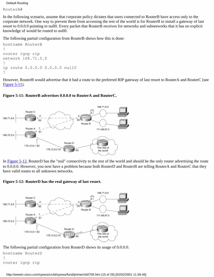
RouterA#
In the following scenario, assume that corporate policy dictates that users connected to RouterB have access only to thecorporate network. One way to prevent them from accessing the rest of the world is for RouterB to install a gateway of lastresort to 0.0.0.0 pointing to null0. Every packet that RouterB receives for networks and subnetworks that it has no explicitknowledge of would be routed to null0.
The following partial configuration from RouterB shows how this is done:
hostname RouterB!router igrp ripnetwork 168.71.0.0!ip route 0.0.0.0 0.0.0.0 null0!
However, RouterB would advertise that it had a route to the preferred RIP gateway of last resort to RouterA and RouterC (seeFigure 5-11).
Figure 5-11: RouterB advertises 0.0.0.0 to RouterA and RouterC.
In Figure 5-12, RouterD has the "real" connectivity to the rest of the world and should be the only router advertising the routeto 0.0.0.0. However, you now have a problem because both RouterD and RouterB are telling RouterA and RouterC that theyhave valid routes to all unknown networks.
Figure 5-12: RouterD has the real gateway of last resort.
The following partial configuration from RouterD shows its usage of 0.0.0.0:
hostname RouterD!router igrp rip
Default Routing
http://wwwin.cisco.com/cpress/cc/td/cpress/fund/primer/cb0705.htm (15 of 29) [02/02/2001 11.59.46]

network 168.71.0.0!ip route 0.0.0.0 0.0.0.0 serial0!
In the following routing table from RouterA, you can see that RouterA has installed two routes to 0.0.0.0:
RouterA#show ip route 0.0.0.0Routing entry for 0.0.0.0 0.0.0.0, supernet Known via "rip", distance 120, metric 1, candidate default path Redistributing via rip Last update from 168.71.6.3 on Serial0, 00:00:01 ago Routing Descriptor Blocks: * 168.71.6.3, from 168.71.6.3, 00:00:10 ago, via Serial0 Route metric is 1, traffic share count is 1 179.12.9.2, from 179.12.9.2 , 00:00:01 ago, via Serial1 Route metric is 1, traffic share count is 1RouterA#
Figure 5-13 shows how the routes map onto the network topology.
Figure 5-13: RouterA has two routes to 0.0.0.0.
Both routes have the same metric, so they are treated as parallel equal-cost paths. Figure 5-14 shows RouterA load sharingpings over the two links.
In the following output from RouterA pinging 132.10.10.1---an address that lives in the rest of the world--- you can see that 40percent of the pings are lost. These are the ones sent to RouterB:
RouterA#ping 132.10.10.1Type escape sequence to abort.Sending 5, 100-byte ICMP Echos to 132.10.10.1, timeout is 2 seconds:!.!.!Success rate is 60 percent (3/5), round-trip min/avg/max = 16/16/16 msRouterA#
This is a classic case of a misconfigured default route. You can prove this by configuring a static route in RouterA to 0.0.0.0via one path and testing it with pings. Then do the same with the other path. The static route overrides the dynamic route to0.0.0.0. The one that works for 100 percent of the pings is the correct path, and the one that fails completely is the broken path.
Figure 5-14: RouterA will load share pings over the two routes to 0.0.0.0.
Default Routing
http://wwwin.cisco.com/cpress/cc/td/cpress/fund/primer/cb0705.htm (16 of 29) [02/02/2001 11.59.46]

In Figure 5-15, you can see the path that RouterC has installed for 0.0.0.0:
Figure 5-15: RouterC has the wrong path
The following routing table from RouterC shows the single route to 0.0.0.0 via RouterB:
RouterC#show ip route 0.0.0.0Routing entry for 0.0.0.0 0.0.0.0, supernet Known via "rip", distance 120, metric 1, candidate default path Redistributing via rip Last update from 168.71.6.3 on Serial0, 00:00:01 ago Routing Descriptor Blocks: * 168.71.6.3, from 168.71.6.3, 00:00:10 ago, via Serial0 Route metric is 1, traffic share count is 1RouterC#
Note that the metric is 1. The other route via RouterD would have a metric of 2. In Figure 5-16, you can see the path pings takefor 132.10.10.1 from RouterC.
Figure 5-16: RouterC can't ping 132.10.10.1.
Default Routing
http://wwwin.cisco.com/cpress/cc/td/cpress/fund/primer/cb0705.htm (17 of 29) [02/02/2001 11.59.46]

In the following output of RouterC pinging 132.10.10.1, you can see that 100 percent of the pings fail:
RouterC#ping 132.10.10.1Type escape sequence to abort.Sending 5, 100-byte ICMP Echos to 132.10.10.1, timeout is 2 seconds:...Success rate is 0 percent (0/5) RouterC#
This proves that RouterC is attempting to use the incorrect route to the gateway of last resort via RouterB because it has alower metric than the path advertised from RouterD via RouterA.
Having discovered that, in this case, RouterB is causing the problem, your fix is to stop RouterB from advertising the route for0.0.0.0 to any other routers. Figure 5-17 shows the places the advertisements for 0.0.0.0 need to be blocked.
Figure 5-17: RouterB's advertisements for 0.0.0.0 must be blocked.
The following partial configuration from RouterB shows how to do this:
!router ripnetwork 168.71.0.0distribute-list 1 out!ip route 0.0.0.0 0.0.0.0 null0!access-list 1 deny 0.0.0.0 0.0.0.0access-list 1 permit 0.0.0.0 255.255.255.255!
access-list 1 denies the default route of 0.0.0.0 with the mask of 0.0.0.0, while allowing all other routes with the permit allstatement of 0.0.0.0 255.255.255.255.
Remember that all access lists have an implicit deny all at the end. If the goal is to permit some traffic that doesn't meet the test
Default Routing
http://wwwin.cisco.com/cpress/cc/td/cpress/fund/primer/cb0705.htm (18 of 29) [02/02/2001 11.59.46]

cases earlier in the access list, the final visible line of the access list must permit the traffic to flow. The implicit deny allremains as the last line. Some people add an explicit deny all of 255.255.255.255 0.0.0.0 at the end of access lists to remindthemselves of the final deny all issue.
The following output of debug ip rip was captured before the configuration to block 0.0.0.0 was added:
RouterB#debug ip ripOct 15 17:50:39: RIP: sending update to 255.255.255.255 via Serial0 (168.71.6.1)Oct 15 17:50:39: subnet 168.71.8.0, metric 1Oct 15 17:50:39: subnet 171.68.0.0, metric 1Oct 15 17:50:39: default 0.0.0.0, metric 1Oct 15 17:50:39: RIP: sending update to 255.255.255.255 via Serial0 (168.71.6.2)Oct 15 17:50:39: subnet 168.71.8.0, metric 1Oct 15 17:50:39: subnet 171.68.0.0, metric 1Oct 15 17:50:39: default 0.0.0.0, metric 1RouterB#
The following output of debug ip rip was captured after the configuration to block 0.0.0.0 was added:
RouterB#debug ip ripOct 15 17:51:07: RIP: sending update to 255.255.255.255 via Serial0 (168.71.6.1)Oct 15 17:50:39: subnet 168.71.8.0, metric 1Oct 15 17:50:39: subnet 171.68.0.0, metric 1Oct 15 17:51:07: RIP: sending update to 255.255.255.255 via Serial1 (168.71.6.2)Oct 15 17:50:39: subnet 168.71.8.0, metric 1Oct 15 17:50:39: subnet 171.68.0.0, metric 1RouterB
As you can see, the access list worked. In the following output from RouterA pinging 132.10.10.1, you can see that they arenow 100 percent successful:
RouterA#ping 132.10.10.1Type escape sequence to abort.Sending 5, 100-byte ICMP Echos to 132.10.10.1, timeout is 2 seconds:!!!!!Success rate is 100 percent (5/5), round-trip min/avg/max = 16/17/20 msRouterA#
In the following output from RouterC pinging 132.10.10.1, you can see that they are now 100 percent successful:
RouterC#ping 132.10.10.1Type escape sequence to abort.Sending 5, 100-byte ICMP Echos to 132.10.10.1, timeout is 2 seconds:!!!!!Success rate is 100 percent (5/5), round-trip min/avg/max = 36/37/40 msRouterC#
Remember that the goal of this scenario was to create an IP network routing plan that prevented the hosts on 168.71.8.0 and168.71.97.0 from reaching any hosts on networks that RouterB did not have explicit routes for.
The original problem was that RouterB was installing the dynamic route for 0.0.0.0 from RouterD and then advertising it to therest of the network. To fix this problem, a static route to 0.0.0.0 pointing at null0 was configured in RouterB. This fixed theoriginal problem but created a new problem.
The new problem was that RouterB started advertising its static route for 0.0.0.0 to the rest of the network. This caused somehosts to install this route instead of, or in conjunction with, their original route to 0.0.0.0, which was being advertised byRouterD. The routers using only RouterB's route to 0.0.0.0, therefore, lost all connectivity to the outside world. Routers thatinstalled RouterB's route to 0.0.0.0 in conjunction with RouterD's lost 50 percent of their connectivity to the rest of the world.
Using 0.0.0.0 with IGRP
Default Routing
http://wwwin.cisco.com/cpress/cc/td/cpress/fund/primer/cb0705.htm (19 of 29) [02/02/2001 11.59.46]

The only difference between the way IGRP uses 0.0.0.0 and the way RIP uses it is that IGRP does not advertise it, even if aredistribute static command and a default metric are configured. The solution for creating a local domain default route forIGRP is given in this scenario. The 0.0.0.0 route might be installed as a gateway of last resort by a router running IGRP, eventhough IGRP---unlike RIP---doesn't treat 0.0.0.0 any differently than any other route. This is because the IP functionality ofthe Cisco IOS itself installs the route, not IGRP.
A router that has not yet been configured with a dynamic routing protocol still must be able to handle some basic IP functions.In fact, some routers use only static routes and connected routes to maintain the IP connectivity they require. These functionsare built into the Cisco IOS to ensure that they are available.
What to Do Instead of Using 0.0.0.0 with IGRP
This section illustrates a previous point about IGRP's behavior when a route to 0.0.0.0 is available. As previously mentioned,the 0.0.0.0 route is automatically installed as the local gateway of last resort for the router by the Cisco IOS. No ip default-network 0.0.0.0 command is required. Also, as previously mentioned, IGRP does not advertise 0.0.0.0 to other routers, even ifredistribute static and a default metric are configured. Figure 5-18 shows the network topology used in this scenario.
Figure 5-18: The three-router topology.
In the following routing table from RouterA, you can see that the static route to null0 for 0.0.0.0 is entered as the gateway oflast resort:
RouterA#show ip routeCodes: C - connected, S - static, I - IGRP, R - RIP, M - mobile, B - BGP D - EIGRP, EX - EIGRP external, O - OSPF, IA - OSPF inter area E1 - OSPF external type 1, E2 - OSPF external type 2, E - EGP i - IS-IS, L1 - IS-IS level-1, L2 - IS-IS level-2, * - candidate defaultGateway of last resort is 0.0.0.0 to network 0.0.0.0 168.71.0.0 255.255.255.0 is subnetted, 5 subnetsC 168.71.9.0 is directly connected, Serial1I 168.71.8.0 [100/80188] via 168.71.9.2, 00:00:30, Serial1I 168.71.7.0 [100/82125] via 168.71.9.2, 00:00:31, Serial1 [100/82125] via 168.71.6.2, 00:01:23, Serial0C 168.71.6.0 is directly connected, Serial0C 168.71.5.0 is directly connected, Ethernet0S* 0.0.0.0 0.0.0.0 is directly connected, Null0RouterA#
The following partial configuration from RouterA shows how this is done:
hostname RouterA!router igrp 109network 168.71.0.0!ip route 0.0.0.0 0.0.0.0 null0!
In the following output of the debug ip igrp transactions command from RouterA, you can see that RouterA is not advertising
Default Routing
http://wwwin.cisco.com/cpress/cc/td/cpress/fund/primer/cb0705.htm (20 of 29) [02/02/2001 11.59.46]

0.0.0.0:
RouterA#debug ip igrp transactionsOct 15 00:42:43: IGRP: sending update to 255.255.255.255 via Serial0 (168.71.6.1)Oct 15 00:42:43: subnet 168.71.9.0, metric=80125Oct 15 00:42:43: subnet 168.71.8.0, metric=80188Oct 15 00:42:43: subnet 168.71.5.0, metric=10000001Oct 15 00:42:43: IGRP: sending update to 255.255.255.255 via Serial1 (168.71.9.1)Oct 15 00:42:43: subnet 168.71.6.0, metric=80125Oct 15 00:42:43: subnet 168.71.5.0, metric=10000001RouterA#
Remember that RIP advertised 0.0.0.0 automatically. The following partial configuration from RouterA shows that a defaultmetric has been configured, as well as redistribute static. RouterA still does not advertise 0.0.0.0.
hostname RouterA!router igrp 109 redistribute static passive-interface Ethernet0 network 168.71.0.0 default-metric 128 2000 255 1 1500!ip route 0.0.0.0 0.0.0.0 null0!
In the following output of the debug ip igrp transactions command from RouterA, you can see that RouterA is still notadvertising 0.0.0.0:
RouterA#debug ip igrp transactionsOct 15 00:44:20: IGRP: sending update to 255.255.255.255 via Serial0 (168.71.6.1)Oct 15 00:44:20: subnet 168.71.9.0, metric=80125Oct 15 00:44:20: subnet 168.71.8.0, metric=80188Oct 15 00:44:20: subnet 168.71.5.0, metric=10000001Oct 15 00:44:20: IGRP: sending update to 255.255.255.255 via Serial1 (168.71.9.1)Oct 15 00:44:20: subnet 168.71.6.0, metric=80125Oct 15 00:44:20: subnet 168.71.5.0, metric=10000001RouterA#
The following partial configuration from RouterA shows how to get RouterA to use 0.0.0.0 as the local default route. It alsoshows how to advertise a different candidate default route--- 10.0.0.0---that other routers can consider as a possible gateway oflast resort. The ip default network command is used to tag a route as a candidate default:
hostname RouterA!router igrp 109 redistribute static network 168.71.0.0 default-metric 128 2000 255 1 1500!ip default-network 10.0.0.0ip route 0.0.0.0 0.0.0.0 null0ip route 10.0.0.0 255.0.0.0 null0!
A router can have multiple default networks configured; however, 0.0.0.0 is the preferred route when it is in the router'srouting table with an equal or better metric than any other candidate default route. Because both routes in RouterA are static,they have identical metrics.
The following routing table from RouterA shows both static routes. Note that the asterisk (*) indicates a candidate default
Default Routing
http://wwwin.cisco.com/cpress/cc/td/cpress/fund/primer/cb0705.htm (21 of 29) [02/02/2001 11.59.46]
route.
RouterA#show ip routeCodes: C - connected, S - static, I - IGRP, R - RIP, M - mobile, B - BGP D - EIGRP, EX - EIGRP external, O - OSPF, IA - OSPF inter area E1 - OSPF external type 1, E2 - OSPF external type 2, E - EGP i - IS-IS, L1 - IS-IS level-1, L2 - IS-IS level-2, * - candidate defaultGateway of last resort is 0.0.0.0 to network 0.0.0.0S* 10.0.0.0 is directly connected, Null0 168.71.0.0 255.255.255.0 is subnetted, 5 subnetsC 168.71.9.0 is directly connected, Serial1I 168.71.8.0 [100/80188] via 168.71.9.2, 00:00:49, Serial1I 168.71.7.0 [100/82125] via 168.71.6.2, 00:01:11, Serial0 [100/82125] via 168.71.9.2, 00:00:49, Serial1C 168.71.6.0 is directly connected, Serial0C 168.71.5.0 is directly connected, Ethernet0S* 0.0.0.0 0.0.0.0 is directly connected, Null0RouterA#
The following routing table from RouterC shows that RouterC has received RouterA's advertisement for 10.0.0.0 and installedit as a gateway of last resort:
RouterC#show ip routeCodes: C - connected, S - static, I - IGRP, R - RIP, M - mobile, B - BGP D - EIGRP, EX - EIGRP external, O - OSPF, IA - OSPF inter area E1 - OSPF external type 1, E2 - OSPF external type 2, E - EGP i - IS-IS, L1 - IS-IS level-1, L2 - IS-IS level-2, * - candidate defaultGateway of last resort is 168.71.9.1 to network 10.0.0.0I* 10.0.0.0 [100/82125] via 168.71.9.1, 00:00:31, Serial1168.71.0.0 255.255.255.0 is subnetted, 5 subnetsC 168.71.9.0 is directly connected, Serial1C 168.71.8.0 is directly connected, TokenRing0C 168.71.7.0 is directly connected, Serial0I 168.71.6.0 [100/82125] via 168.71.9.1, 00:00:32, Serial1 [100/82125] via 168.71.7.2, 00:00:27, Serial0I 168.71.5.0 [100/10002001] via 168.71.9.1, 00:00:32, Serial1RouterC#
The 0.0.0.0 route is not as useful for IGRP as it is for RIP. However, it is safer to use with IGRP for the same reasons that it isnot as useful.
The simplest way to achieve the same effect for IGRP is to create and redistribute a static route for a fictitious network andflag it as the IP default network. You don't want to use a real network because you may not be able to control where the routefor the real network is learned from. It may not always be learned via the path on which you want your traffic to travel.
If you have multiple routers with exit points to other networks that you want to use as redundant links to the outside world, youcan configure the same redistributed static route in each of them. If you want one to always be preferred over the others, give ita much better metric. Make certain that, for any router in the network, the metric for the preferred route is better than themetric it receives from another router's candidate default.
Using End Systems with Multiple Local GatewaysCurrently, it is not uncommon for an end system to have more than one local gateway. Unfortunately, this is one of theweakest areas of IP routing. It is readily apparent that, when the concept of IP gateways for end systems was being consideredby those writing IP protocol stacks, it was not common to have more than one local gateway.
In Figure 5-19, the PC on the Token Ring has two possible gateways to reach 168.71.5.0. Because most PCs running Windowsare not usually running a dynamic routing protocol, they are restricted to using a single gateway at a time. In this case, the PC
Default Routing
http://wwwin.cisco.com/cpress/cc/td/cpress/fund/primer/cb0705.htm (22 of 29) [02/02/2001 11.59.46]

can use either RouterB or RouterC to reach 168.71.5.0---but not both. If RouterA failed while a PC was using it, the PC wouldhave to be reconfigured to use RouterB.
Figure 5-19: A review of the three-router topology.
In addition, the PC cannot load balance traffic between the two routers, even though the links connecting the routers have thesame amount of bandwidth (both 56k or T1).
Traffic from the PC on the Ethernet is load balanced because RouterA has two parallel links that are considered to be of equalcost in this example. Note that this PC has only one gateway.
In an ideal world, end systems would be able to dynamically learn how many gateways were available off of their localnetwork, what remote networks each gateway could reach, and the operational status of any gateways.
ICMP Router Discovery Protocol (IRDP) RFC 1256
IRDP RFC 1256 is the ICMP Router Discovery Protocol that runs on routers and end systems so that routers can advertisethemselves to end stations and end stations can listen to the advertisements. By listening to these advertisements, end stationscan dynamically select a gateway for reaching non-local networks. RFC 1256 allows one router to be preferred over anotherand provides other options for controlling the behavior of systems running IRDP.
The simplest configuration commands for IRDP in a Cisco router are as follows:
!interface tokenring0ip address 168.71.8.1 255.255.255.0ip irdp!
A thorough discussion of RFC 1256 is beyond the scope of this book. See the Cisco IOS documentation for the version of IOSyou are using for more information on Cisco's implementation of IRDP.
This RFC is available on any site that makes RFCs available via anonymous FTP. It can be found on Cisco's CCO FTP serveras follows: FTP to cco.cisco.com username=anonymous, password=your_full_email_address. The FTP client must run inpassive mode. (FTP server assigns the client's FTP port for the session. Go to /pub/rfc/RFC.)
End Systems Using RIP
End systems that can run RIP are somewhat better off. They can listen to routing updates and react to changes in the networkaccordingly. However, RIP V1 on an end system shares all of the limitations of RIP V1 on a router---no VLSM support, nodiscontiguous network support, and no capability to understand the actual speed of any network so that two parallel links arealways of equal cost even when they are different bandwidths (one 56k and one T1).
In Figure 5-20, the end system on the Token Ring could determine that the path to 168.71.5.0 via RouterB has only one hop,while the path has two. Unfortunately, RIP V1 can't understand that the bandwidth of the one-hop path is much slower, makingthe two-hop path a better path.
Figure 5-20: The one-hop path is slower than the two-hop path.
Default Routing
http://wwwin.cisco.com/cpress/cc/td/cpress/fund/primer/cb0705.htm (23 of 29) [02/02/2001 11.59.46]
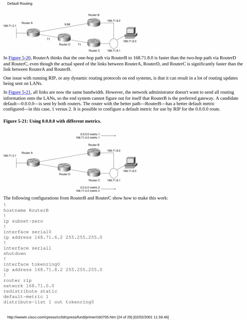
In Figure 5-20, RouterA thinks that the one-hop path via RouterB to 168.71.8.0 is faster than the two-hop path via RouterDand RouterC, even though the actual speed of the links between RouterA, RouterD, and RouterC is significantly faster than thelink between RouterA and RouterB.
One issue with running RIP, or any dynamic routing protocols on end systems, is that it can result in a lot of routing updatesbeing sent on LANs.
In Figure 5-21, all links are now the same bandwidth. However, the network administrator doesn't want to send all routinginformation onto the LANs, so the end system cannot figure out for itself that RouterB is the preferred gateway. A candidatedefault---0.0.0.0---is sent by both routers. The router with the better path---RouterB---has a better default metricconfigured---in this case, 1 versus 2. It is possible to configure a default metric for use by RIP for the 0.0.0.0 route.
Figure 5-21: Using 0.0.0.0 with different metrics.
The following configurations from RouterB and RouterC show how to make this work:
!hostname RouterB!ip subnet-zero!interface serial0ip address 168.71.6.2 255.255.255.0!interface serial1shutdown!interface tokenring0ip address 168.71.8.2 255.255.255.0!router ripnetwork 168.71.0.0redistribute staticdefault-metric 1distribute-list 1 out tokenring0
Default Routing
http://wwwin.cisco.com/cpress/cc/td/cpress/fund/primer/cb0705.htm (24 of 29) [02/02/2001 11.59.46]

distribute-list 2 out serial0!ip route 168.71.0.0 255.255.255.0 null0ip route 0.0.0.0 0.0.0.0 null0!access-list 1 permit 0.0.0.0 0.0.0.0access-list 1 permit 168.71.0.0 0.0.0.0access-list 2 deny 0.0.0.0 0.0.0.0access-list 2 deny 168.71.0.0 0.0.0.0access-list 2 permit 0.0.0.0 255.255.255.255!
For RIP V1 and IGRP, the static route to 168.71.0.0 must have the same mask as the Token Ring interface in order for it to beadvertised over the Token Ring. (See the VLSM section for more details.) Therefore, the ip subnet-zero command must beconfigured when using RIP V1 and IGRP because the static route 168.71.0.0 255.255.255.0 is pointing at subnet 0 of the168.71.0.0 major net. This command enables you to use ip subnet-zero in a router for static routes or as a subnet on aninterface.
The distribute lists ensure that only the 0.0.0.0 and 168.71.0.0 routes are advertised out the Token Ring and that these tworoutes are not advertised out the serial interfaces.
The access lists are used by the distribute lists. The default metric command is used to ensure that the static routes to 0.0.0.0and 168.71.0.0 advertised by RouterB are preferred over the same routes advertised by RouterC. RouterC uses a default metricof 2.
!hostname RouterC!ip subnet-zero!interface serial0shutdown!interface serial1ip address 168.71.9.2 255.255.255.0!interface tokenring0ip address 168.71.8.2 255.255.255.0!router ripnetwork 168.71.0.0redistribute staticdefault-metric 2distribute-list 1 out tokenring0distribute-list 2 out serial1!ip route 168.71.0.0 255.255.255.0 null0ip route 0.0.0.0 0.0.0.0 null0!access-list 1 permit 0.0.0.0 0.0.0.0access-list 1 permit 168.71.0.0 0.0.0.0access-list 2 deny 0.0.0.0 0.0.0.0access-list 2 deny 168.71.0.0 0.0.0.0access-list 2 permit 0.0.0.0 255.255.255.255!
Default Routing
http://wwwin.cisco.com/cpress/cc/td/cpress/fund/primer/cb0705.htm (25 of 29) [02/02/2001 11.59.46]

Cisco's Hot Standby Router Protocol (HSRP)
Hot Standby Router Protocol (HSRP) is a Cisco proprietary protocol for handling multiple gateways on a LAN. It does so byhaving the gateways share an IP address and a MAC address. One of the gateway's interfaces to the common LAN is inSTANDBY mode, while the other's interface is in ACTIVE mode. In the event that the ACTIVE interface or router goes down,the STANDBY interface goes live.
Routers configured for HSRP send information to each other indicating that they will receive even if their interface is instandby mode. This is accomplished by using special functional MAC addresses reserved only for HSRP packets. A routerwhose interface is in standby mode accepts frames addressed to this MAC address, ignoring all other frames.
Note A router configured for HSRP uses its original IP address and MAC address on the interface, as well as the Hot StandbyIP address and special MAC address when they are active. Therefore, it is possible to use the original IP addresses for Telnetsessions and SNMP monitoring even when the router is the active HSRP router. In addition, the Hot Standby IP address andthe MAC address can be active on only one router at a time.
In Figure 5-22, the end system has two gateways but can use only one at a time. Without HSRP, the end system would have tobe reconfigured if the default gateway it was configured for failed. With HSRP, the router with the standby interface learnsabout the failure of the other gateway because that gateway has ceased sending HSRP packets. This router places its interfaceinto forwarding mode.
Because the HSRP routers are acting as if their interfaces have the same IP address---in this case, 168.71.8.3---and MACaddress, the end system keeps using the gateway IP address it was configured with, as well as the MAC address it ARPed for.Remember that the layer two MAC addresses are point to point on the same physical LAN, whereas the layer three IPaddresses travel end to end.
Figure 5-22: Multiple gateways.
The following partial configuration from RouterB shows that RouterB has the highest standby priority and therefore owns theprimary HSRP interface in any negotiation between RouterB and RouterC. The standby IP address is 168.71.8.3. This is theaddress that the end system uses as its default gateway.
RouterC#!interface tokenring0 ip address 168.71.8.1 255.255.255.0 standby preempt standby 1 priority 110 standby 1 preempt standby 1 ip 168.71.8.3!
The following output of the show standby command from RouterC shows that RouterC is the standby router and that RouterBis the active router:
RouterC#sh standbyTokenring0 - Group 1 Local state is Standby, priority 110, may preempt Hellotime 3 holdtime 10
Default Routing
http://wwwin.cisco.com/cpress/cc/td/cpress/fund/primer/cb0705.htm (26 of 29) [02/02/2001 11.59.46]
Next hello sent in 0:00:00 Hot standby IP address is 168.71.8.3 configured Active router is 168.71.8.2 expires in 0:00:08 Standby router is local
The following partial configuration from RouterB shows RouterB's HSRP configuration commands:
RouterB#!interface tokenring0 ip address 168.71.8.2 255.255.255.0 standby 1 priority 120 standby 1 preempt standby 1 ip 168.71.8.3!
The following output of the show standby command from RouterB shows that RouterC is the standby router and that RouterBis the active router:
RouterB#sh standEthernet0 - Group 1 Local state is Active, priority 120, may preempt Hellotime 3 holdtime 10 Next hello sent in 0:00:00 Hot standby IP address is 168.71.8.3 configured Active router is local Standby router is 168.71.8.1 expires in 0:00:09!
This was a purposely brief introduction of HSRP. A thorough discussion of HSRP is beyond the scope of this book. See theCisco IOS documentation for the version of IOS you are using for more information on Cisco's implementation of HSRP.
Using Floating Static RoutesFloating static routes are static routes that are always in the configuration of a router but are only installed in a routing tablewhen a dynamic route to the same network is lost. The dynamic route overrides the static route because the static route isconfigured with a greater distance. The concept of distance was introduced in the section on metrics and distances in "RoutingMetrics and Distances."
This type of static route can be used when the alternative link is a dial-up connection. Dynamic routing information is notusually sent or received over a dial-up link unless the link is intended to be up for a long period of time. Remember thatdynamic routing protocols send updates at regular intervals, causing the link to go up and down on a regular basis.
This scenario provides a real-life example of a floating static route being installed in a routing table after the lower-cost(shorter-path or lower-metric) routes are removed.
In Figure 5-23, the link between RouterA and RouterC is now an ISDN connection. This link is used when the primary linkbetween RouterA and RouterB goes down.
Figure 5-23: RouterA and RouterC have an ISDN connection.
Default Routing
http://wwwin.cisco.com/cpress/cc/td/cpress/fund/primer/cb0705.htm (27 of 29) [02/02/2001 11.59.46]
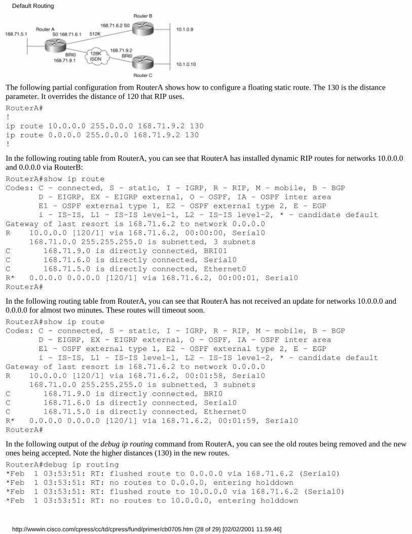
The following partial configuration from RouterA shows how to configure a floating static route. The 130 is the distanceparameter. It overrides the distance of 120 that RIP uses.
RouterA#!ip route 10.0.0.0 255.0.0.0 168.71.9.2 130ip route 0.0.0.0 255.0.0.0 168.71.9.2 130!
In the following routing table from RouterA, you can see that RouterA has installed dynamic RIP routes for networks 10.0.0.0and 0.0.0.0 via RouterB:
RouterA#show ip routeCodes: C - connected, S - static, I - IGRP, R - RIP, M - mobile, B - BGP D - EIGRP, EX - EIGRP external, O - OSPF, IA - OSPF inter area E1 - OSPF external type 1, E2 - OSPF external type 2, E - EGP i - IS-IS, L1 - IS-IS level-1, L2 - IS-IS level-2, * - candidate defaultGateway of last resort is 168.71.6.2 to network 0.0.0.0R 10.0.0.0 [120/1] via 168.71.6.2, 00:00:00, Serial0 168.71.0.0 255.255.255.0 is subnetted, 3 subnetsC 168.71.9.0 is directly connected, BRI01C 168.71.6.0 is directly connected, Serial0C 168.71.5.0 is directly connected, Ethernet0R* 0.0.0.0 0.0.0.0 [120/1] via 168.71.6.2, 00:00:01, Serial0RouterA#
In the following routing table from RouterA, you can see that RouterA has not received an update for networks 10.0.0.0 and0.0.0.0 for almost two minutes. These routes will timeout soon.
RouterA#show ip routeCodes: C - connected, S - static, I - IGRP, R - RIP, M - mobile, B - BGP D - EIGRP, EX - EIGRP external, O - OSPF, IA - OSPF inter area E1 - OSPF external type 1, E2 - OSPF external type 2, E - EGP i - IS-IS, L1 - IS-IS level-1, L2 - IS-IS level-2, * - candidate defaultGateway of last resort is 168.71.6.2 to network 0.0.0.0R 10.0.0.0 [120/1] via 168.71.6.2, 00:01:58, Serial0 168.71.0.0 255.255.255.0 is subnetted, 3 subnetsC 168.71.9.0 is directly connected, BRI0C 168.71.6.0 is directly connected, Serial0C 168.71.5.0 is directly connected, Ethernet0R* 0.0.0.0 0.0.0.0 [120/1] via 168.71.6.2, 00:01:59, Serial0RouterA#
In the following output of the debug ip routing command from RouterA, you can see the old routes being removed and the newones being accepted. Note the higher distances (130) in the new routes.
RouterA#debug ip routing*Feb 1 03:53:51: RT: flushed route to 0.0.0.0 via 168.71.6.2 (Serial0)*Feb 1 03:53:51: RT: no routes to 0.0.0.0, entering holddown*Feb 1 03:53:51: RT: flushed route to 10.0.0.0 via 168.71.6.2 (Serial0)*Feb 1 03:53:51: RT: no routes to 10.0.0.0, entering holddown
Default Routing
http://wwwin.cisco.com/cpress/cc/td/cpress/fund/primer/cb0705.htm (28 of 29) [02/02/2001 11.59.46]
*Feb 1 03:53:51: RT: flushed route to 168.71.7.0 via 168.71.6.2 (Serial0)RouterA#*Feb 1 03:54:45: RT: garbage collecting entry for 0.0.0.0*Feb 1 03:54:45: RT: garbage collecting entry for 10.0.0.0*Feb 1 03:55:13: RT: add 0.0.0.0 0.0.0.0 via 168.71.9.2, static metric [130/0]*Feb 1 03:55:13: RT: add 10.0.0.0 255.0.0.0 via 168.71.9.2, static metric [130/0]*Feb 1 03:55:13: RT: default path is now 0.0.0.0 via 168.71.9.2*Feb 1 03:55:13: RT: new default network 0.0.0.0
In the following routing table from RouterA, you can see the new routes installed:
RouterA#show ip routeCodes: C - connected, S - static, I - IGRP, R - RIP, M - mobile, B - BGP D - EIGRP, EX - EIGRP external, O - OSPF, IA - OSPF inter area E1 - OSPF external type 1, E2 - OSPF external type 2, E - EGP i - IS-IS, L1 - IS-IS level-1, L2 - IS-IS level-2, * - candidate defaultGateway of last resort is 168.71.9.2 to network 0.0.0.0S 10.0.0.0 [130/0] via 168.71.9.2 168.71.0.0 255.255.255.0 is subnetted, 3 subnetsC 168.71.9.0 is directly connected, Serial1C 168.71.6.0 is directly connected, Serial0C 168.71.5.0 is directly connected, Ethernet0S* 0.0.0.0 0.0.0.0 [130/0] via 168.71.9.2RouterA#
The dial-on-demand routing (DDR) commands necessary to actually cause RouterA to make an ISDN call to RouterC have notbeen included. DDR is beyond the scope of this book. The key factor needed for DDR to work is that the router must decidethat the dial-up interface is the correct interface to use for forwarding a packet to its next hop.
In this scenario, RouterA has just installed routes that will cause it to forward packets destined to 10.1.0.0 via its ISDNinterface. Assuming that the DDR commands are properly configured, the call should be made and a connection should beestablished.
SummaryThis chapter has touched on some fundamental issues regarding IP connectivity to non-local networks. This is probably one ofthe most complex aspects of IP internetworking. Multiple factors need to be considered when deciding the best way toimplement connectivity to non-local subnets.
These factors also come into play when it becomes necessary to troubleshoot an IP connectivity problem. It is not uncommonfor a network administrator to discover IP packets wandering aimlessly around the network looking for a home. Sometimesthese packets are not worth looking into. Other times, when they are wasting precious bandwidth on low-speed circuits, theyneed to be tracked down and eliminated. The next chapter discusses the next step---introducing some basic troubleshootingtechniques and scenarios.
Posted: Wed Mar 3 10:02:12 PST 1999Copyright 1989-1999©Cisco Systems Inc.Copyright © 1997 Macmillan Publishing USA, a Simon & Schuster Company
Default Routing
http://wwwin.cisco.com/cpress/cc/td/cpress/fund/primer/cb0705.htm (29 of 29) [02/02/2001 11.59.46]

Table of Contents
IP Troubleshooting Scenarios
Developing a Troubleshooting RoutineUsing a Troubleshooting Scenario
Checking the Available RoutesTracing the RouteUsing Extended Pings to Track ConnectivityOther Possible Problems
An ARP ProblemValidating End System Routing Tables
Summary
IP Troubleshooting ScenariosThis chapter covers aspects of troubleshooting IP connectivity problems that have not yet been discussed. It is not intended tobe an in-depth analysis of IP network troubleshooting. However, it does cover some of the fundamental skills that anyonesupporting an IP network should have.
The troubleshooting methodology presented is very structured. It uses the process of elimination to isolate the failure to theroot symptom. Like many network failures, the root cause of the failure in this scenario may never be known.
Developing a Troubleshooting RoutineTroubleshooting techniques vary significantly from one network engineer to another. They are part science and part artistry. Agood network engineer can simultaneously think in a linear fashion (following a logical progression of an event from start tofinish) and in a lateral fashion (considering events not directly related to the problem at hand but possibly having an effect).
In general, there is no one correct way to determine the root cause of a problem. However, there are a few guidelines you canfollow:
Determine as far as possible exactly what problem you are trying to solve and focus on it. Networks are a lot like cars:You can start out investigating one problem and find 10 other things that may need attention. Make a note of anynon-related problems, but focus on investigating the primary problem.
●
If several users are reporting problems from different areas of the network at the same time, there is a good chance thatthey are reporting elements of the same problem. Focus on one area at a time. It can be overwhelming to have 1,000 ormore users down at once, but if the same problem is simply reoccurring in multiple parts of the network, you only haveto figure it out once.
●
Whenever possible, try to duplicate the problem in a lab and troubleshoot it there. Often, the act of troubleshooting aproblem has a greater negative impact on the end-user population than the original problem.
●
If any test requires reconfiguring a device, ensure that you can roll back the change after the test, or you may find thatyou have backed yourself into a corner and cannot proceed.
●
Use as few tests as possible to isolate and define the problem.●
Ensure that the results of the tests are unambiguous.●
Validate the test results by repeating each one at least twice. Note that running a command to verify a configurationparameter is not considered a test in this sense and therefore doesn't need to be performed twice.
●
IP Troubleshooting Scenarios
http://wwwin.cisco.com/cpress/cc/td/cpress/fund/primer/cb0706.htm (1 of 9) [02/02/2001 12.00.09]

Document the tests performed and the results in case a bug is found.●
Document any changes made to the network during the troubleshooting procedure so that the network can be properlyrestored to its original condition.
●
Document any workarounds that were left in place so that other support personnel will be able to understand how andwhy the network changed.
●
Using a Troubleshooting ScenarioThe problem in this fictional scenario is that end systems A and B cannot ping each other. (Assume that the Frame Relaynetwork is fully functional.) End system A is a Sun Classic running Solaris 2.5, and end system B is a PC running Windows95, as shown in Figure 6-1.
Figure 6-1: A and B cannot ping each other.
Checking the Available Routes
In the following output of the show ip route 168.71.8.2 from RouterA, you can see that RouterA has a route to the subnet thatPC-B is on:
RouterA#show ip route 168.71.8.2Routing entry for 168.71.8.0 255.255.255.0 Known via "rip", distance 120, metric 1 Redistributing via rip Last update from 168.71.6.3 on Serial1, 00:00:13 ago Routing Descriptor Blocks: * 168.71.6.3, from 168.71.6.3, 00:00:13 ago, via Serial1 Route metric is 1, traffic share count is 1RouterB#
In the following output of the show ip route 168.72.5.2 from RouterB, you can see that RouterB has a route to this subnet:
RouterB#show ip route 168.72.5.2Routing entry for 168.71.8.0 255.255.255.0 Known via "rip", distance 120, metric 1 Redistributing via rip Last update from 168.71.6.1 on Serial0, 00:00:23 ago Routing Descriptor Blocks: * 168.71.6.1, from 168.71.6.1, 00:00:13 ago, via Serial0 Route metric is 1, traffic share count is 1RouterB#
The previous test has validated that the two routers have knowledge of the subnets that Sun-A and PC-B are on.
IP Troubleshooting Scenarios
http://wwwin.cisco.com/cpress/cc/td/cpress/fund/primer/cb0706.htm (2 of 9) [02/02/2001 12.00.09]

Tracing the Route
Another useful tool is the TraceRoute utility. It is used to trace a route (path) between a device and a host on a remote networkor subnetwork address. Most systems with a TCP/IP protocol stack have a version of this utility. In Windows 95, it is calledtracert.exe. It is usually found in the Windows directory.
The following output of the tracert 168.71.8.2 command from SUN-A shows that the trace dies after reaching RouterB. Notethat SUN-A resolved the Domain Name System (DNS) entry for PC-B before attempting the trace:
SUN-A> traceroute 168.71.8.2traceroute to pc-b.cisco.com (168.71.8.2), 30 hops max, 40 byte packets 1 routerb (168.71.6.3) 3 ms 3 ms 3 ms 2 * * * 3 * * * 4 * * * 5 * * *SUN-A>
The following output of the tracert 168.72.5.2 command from PC-B shows that the trace never really starts. It was necessary tokill the tracert session by pressing CTRL-C (^C). This typically means that the PC cannot reach its first gateway:
c:\windows\ > tracert 168.72.5.2c:\windows\ >
You can test whether the PC is running tracert correctly by tracing the route to itself:
c:\windows\ > tracert 168.71.8.2Tracing route to 168.71.8.2 over a maximum of 30 hops: 1 2 ms 3 ms 2 ms 168.71.6.3Trace complete.c:\windows\ >
If, for any reason, the PC fails to run tracert correctly, it appears to freeze after you enter the tracert command.
c:\windows\ > tracert 168.71.8.2
If this happens, you need to terminate the operation by pressing CTRL-C (^C). You can then use the winipcfg.exe utility toverify that you have an IP address. At a DOS command prompt, type winipcfg, which will bring up the Windows IPconfiguration tracking utility. It can tell you everything there is to know about the IP configuration of the PC (see Figures 6-2and 6-3).
Figure 6-2: The simple view of winipcfg.
:cb070602.tif
Figure 6-3: The detailed view of winipcfg.
:cb070603.tif
c:\windows\ > winipcfg
If your IP address appears as 0.0.0.0, your system doesn't have an IP address configured. Contact your system administrator orrefer to the Microsoft documentation on configuring the TCP/IP protocol. If an IP address appears but is not the address youexpected, try running tracert on this address. It should work.
In this case, PC-B appears to be running tracert.exe correctly. Note that the address was not resolved to a DNS entry, possiblybecause PC-B could not reach its DNS server.
The problem now appears to be that PC-B cannot reach its local gateway, which prevents PC-B from reaching any hosts ondifferent subnets or networks.
Note Cisco routers also have a TraceRoute utility that can be run from a command prompt. The syntax is traceroute
IP Troubleshooting Scenarios
http://wwwin.cisco.com/cpress/cc/td/cpress/fund/primer/cb0706.htm (3 of 9) [02/02/2001 12.00.09]
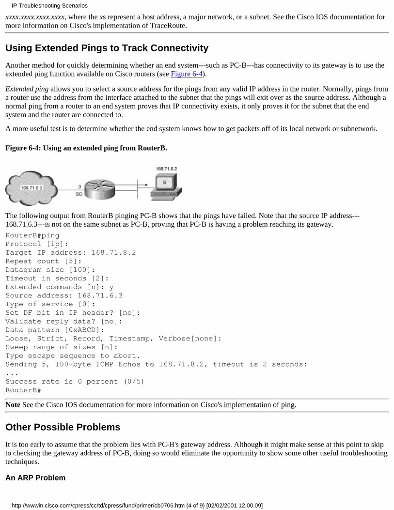
xxxx.xxxx.xxxx.xxxx, where the xs represent a host address, a major network, or a subnet. See the Cisco IOS documentation formore information on Cisco's implementation of TraceRoute.
Using Extended Pings to Track Connectivity
Another method for quickly determining whether an end system---such as PC-B---has connectivity to its gateway is to use theextended ping function available on Cisco routers (see Figure 6-4).
Extended ping allows you to select a source address for the pings from any valid IP address in the router. Normally, pings froma router use the address from the interface attached to the subnet that the pings will exit over as the source address. Although anormal ping from a router to an end system proves that IP connectivity exists, it only proves it for the subnet that the endsystem and the router are connected to.
A more useful test is to determine whether the end system knows how to get packets off of its local network or subnetwork.
Figure 6-4: Using an extended ping from RouterB.
The following output from RouterB pinging PC-B shows that the pings have failed. Note that the source IP address---168.71.6.3---is not on the same subnet as PC-B, proving that PC-B is having a problem reaching its gateway.
RouterB#pingProtocol [ip]:Target IP address: 168.71.8.2Repeat count [5]:Datagram size [100]:Timeout in seconds [2]:Extended commands [n]: ySource address: 168.71.6.3Type of service [0]:Set DF bit in IP header? [no]:Validate reply data? [no]:Data pattern [0xABCD]:Loose, Strict, Record, Timestamp, Verbose[none]:Sweep range of sizes [n]:Type escape sequence to abort.Sending 5, 100-byte ICMP Echos to 168.71.8.2, timeout is 2 seconds:...Success rate is 0 percent (0/5)RouterB#
Note See the Cisco IOS documentation for more information on Cisco's implementation of ping.
Other Possible Problems
It is too early to assume that the problem lies with PC-B's gateway address. Although it might make sense at this point to skipto checking the gateway address of PC-B, doing so would eliminate the opportunity to show some other useful troubleshootingtechniques.
An ARP Problem
IP Troubleshooting Scenarios
http://wwwin.cisco.com/cpress/cc/td/cpress/fund/primer/cb0706.htm (4 of 9) [02/02/2001 12.00.09]

It is not unheard of to encounter a problem with the ARP process. An ARP entry can be corrupted. Another example is that thegateway interface MAC address changes when someone installs a new interface. The end system's ARP entry for the oldIP/MAC address combination might not have timed out yet, which would cause the end system to send packets to the wronglayer two (MAC) address.
Remember that layer two addresses represent point-to-point connectivity on the physical LAN, to which the end system andthe gateway are attached. IP addresses, in contrast, represent end-to-end connectivity.
Note Cisco routers do not have the problem of changing the MAC addresses for interfaces when the physical interfacesthemselves are changed because Cisco routers download the MAC address for interfaces from a table of addresses held inmemory on the system board that holds the CPU. In a 7500-based system, the MAC addresses are held on the RSP.
In the following output from the show arp command on RouterB, you can see the IP/MAC addresses in use. On Cisco routers,the show interface command shows the MAC addresses assigned to the interfaces. On a Windows 95 system, the winipcfg.exeutility shows the MAC address in use by the PC.
RouterB#show arpProtocol Address Age (min) Hardware Addr Type InterfaceInternet 168.71.8.1 - 0000.0c0a.50ca ARPA Ethernet0Internet 168.72.8.2 1 0060.9733.e9f5 ARPA Ethernet0
In this scenario, the IP/MAC addresses appear correct. You can compare them to the addresses on PC-B. The arp -a commandis a fairly universal method for displaying an ARP table on a device running TCP/IP:
C:\WINDOWS>arp -aInterface: 168.71.8.2 Internet Address Physical Address Type 168.71.8.2 00-60-97-33-e9-f5 dynamic 168.71.8.1 00-00-0c-0a-50-ca dynamicC:\WINDOWS>
The following output of arp -a from SUN-A is provided for reference only. You already know that SUN-A can reach its localgateway.
SUN-A > arp -aNet to Media TableDevice IP Address Mask Flags Phys Addr------ -------------------- --------------- ----- ---------------le0 168.72.5.1 255.255.255.255 00:00:0c:32:93:95le0 168.72.5.2 255.255.255.255 SP 00:80:5f:78:79:71SUN-A>
Because the addresses match, it is probably safe to assume that they are correct. Therefore, the problem lies elsewhere.
Validating End System Routing Tables
The problem now appears to be with PC-B's gateway entry. This section explains how to verify this hypothesis and how tomake a temporary change. You previously verified that SUN-A's use of its gateway is correct. The methods for analyzing itsrouting table are presented in this section for reference purposes only.
Although neither end system is running a dynamic routing protocol, they both still have routing tables. The information inthese tables is derived from configuration files when the systems start.
Note It is possible to manipulate these routing tables temporarily by using the procedures provided in this section. Making thechanges permanent requires that the configuration files themselves be modified, which is beyond the scope of this book.Consult the system administrator or the system reference guide for the system in question.
By displaying the routing table on PC-B, you can find the problem. The default route of 0.0.0.0 0.0.0.0 is pointing to the wronggateway address: 168.71.8.10. The correct gateway is 168.71.8.1:
IP Troubleshooting Scenarios
http://wwwin.cisco.com/cpress/cc/td/cpress/fund/primer/cb0706.htm (5 of 9) [02/02/2001 12.00.09]

C:\WINDOWS>netstat -rnRoute TableActive Routes: Network Address Netmask Gateway Address Interface Metric 0.0.0.0 0.0.0.0 168.71.8.10 168.71.8.2 1 168.71.8.0 255.255.255.0 168.71.8.1 168.71.8.2 1 168.71.8.2 255.255.255.255 127.0.0.1 127.0.0.1 1 168.71.0.0 255.255.0.0 168.71.8.1 168.71.8.2 1 168.71.255.255 255.255.255.255 168.71.8.2 168.71.8.2 1 127.0.0.0 255.0.0.0 127.0.0.1 127.0.0.1 1 224.0.0.0 224.0.0.0 168.71.8.2 168.71.8.2 1 255.255.255.255 255.255.255.255 168.71.8.2 168.71.8.2 1Active Connections Proto Local Address Foreign Address StateC:\WINDOWS>
The following is how you flush existing gateways and add a new gateway dynamically in Windows 95 using a DOS commandprompt:
C:\WINDOWS>route -f add 0.0.0.0 mask 0.0.0.0 168.71.8.1
The following routing table from PC-B shows the correct gateway address in place:
C:\WINDOWS>netstat -rnRoute TableActive Routes: Network Address Netmask Gateway Address Interface Metric 0.0.0.0 0.0.0.0 168.71.8.1 168.71.8.2 1 168.71.8.0 255.255.255.0 168.71.8.1 168.71.8.2 1 168.71.8.2 255.255.255.255 127.0.0.1 127.0.0.1 1 168.71.0.0 255.255.0.0 168.71.8.1 168.71.8.2 1 168.71.255.255 255.255.255.255 168.71.8.2 168.71.8.2 1 127.0.0.0 255.0.0.0 127.0.0.1 127.0.0.1 1 224.0.0.0 224.0.0.0 168.71.8.2 168.71.8.2 1 255.255.255.255 255.255.255.255 168.71.8.2 168.71.8.2 1Active Connections Proto Local Address Foreign Address StateC:\WINDOWS>
To make the same kind of a change on a Solaris system (and most other UNIX systems), use the following syntax (as ROOT):
IP Troubleshooting Scenarios
http://wwwin.cisco.com/cpress/cc/td/cpress/fund/primer/cb0706.htm (6 of 9) [02/02/2001 12.00.09]

SUN-A# route add default 168.71.5.1 1add net default: gateway 168.71.5.1
Note The second line shown in the previous UNIX output (add net default: gateway 168.71.5.1) is SUN-A echoing thecommand back to the terminal prompt. The word default and the address 0.0.0.0 can be used interchangeably.
Again, you use the netstat -rn command to display the routing table---the default equals 0.0.0.0:
SUN-A# netstat -rnRouting Table: Destination Gateway Flags Ref Use Interface-------------------- -------------------- ----- ----- ------ ---------127.0.0.1 127.0.0.1 UH 0 80 lo0224.0.0.0 168.71.5.2 U 3 0 le0default 168.71.5.1 UG 0 3622SUN-A>
The following output of the route command from PC-B shows the various options this command can accept. The syntax onUNIX systems and NT systems is very similar. You can typically find out the available options by entering the route commandwithout any options after it. This is how the information that follows was created.
Remember that these commands are only temporary. Rebooting the PC will restore the defaults.
C:\WINDOWS\Desktop>routeManipulates network routing tables.ROUTE [-f] [command [destination] [MASK netmask] [gateway]] -f Clears the routing tables of all gateway entries. If this is used in conjunction with one of the commands, the tables are cleared prior to running the command. command Specifies one of four commands PRINT Prints a route ADD Adds a route DELETE Deletes a route CHANGE Modifies an existing route destination Specifies the host to send command. MASK If the MASK keyword is present, the next parameter is interpreted as the netmask parameter. netmask If provided, specifies a subnet mask value to be associated with this route entry. If not specified, if defaults to 255.255.255.255. gateway Specifies gateway.All symbolic names used for destination or gateway are looked up in thenetwork and host name database files NETWORKS and HOSTS, respectively. Ifthe command is print or delete, wildcards may be used for the destination andgateway, or the gateway argument may be omitted.C:\WINDOWS\Desktop>
Following is an example of adding and then deleting a route on PC-B:
C:\WINDOWS>route add 171.68.97.0 mask 255.255.255.0 168.71.8.1C:\WINDOWS>netstat -rnRoute TableActive Routes: Network Address Netmask Gateway Address Interface Metric 0.0.0.0 0.0.0.0 168.71.8.1 168.71.8.2 1 168.71.8.0 255.255.255.0 168.71.8.1 168.71.8.2
IP Troubleshooting Scenarios
http://wwwin.cisco.com/cpress/cc/td/cpress/fund/primer/cb0706.htm (7 of 9) [02/02/2001 12.00.09]

1 168.71.8.2 255.255.255.255 127.0.0.1 127.0.0.1 1 168.71.0.0 255.255.0.0 168.71.8.1 168.71.8.2 1 168.71.255.255 255.255.255.255 168.71.8.2 168.71.8.2 1 171.68.97.0 255.255.255.0 168.71.8.1 168.71.8.2 1 127.0.0.0 255.0.0.0 127.0.0.1 127.0.0.1 1 224.0.0.0 224.0.0.0 168.71.8.2 168.71.8.2 1 255.255.255.255 255.255.255.255 168.71.8.2 168.71.8.2 1Active Connections Proto Local Address Foreign Address StateC:\WINDOWS>C:\WINDOWS>route delete 171.68.97.0 mask 255.255.255.0 168.71.8.1C:\WINDOWS>netstat -rnRoute TableActive Routes: Network Address Netmask Gateway Address Interface Metric 0.0.0.0 0.0.0.0 168.71.8.1 168.71.8.2 1 168.71.8.0 255.255.255.0 168.71.8.1 168.71.8.2 1 168.71.8.2 255.255.255.255 127.0.0.1 127.0.0.1 1 168.71.0.0 255.255.0.0 168.71.8.1 168.71.8.2 1 168.71.255.255 255.255.255.255 168.71.8.2 168.71.8.2 1 127.0.0.0 255.0.0.0 127.0.0.1 127.0.0.1 1 224.0.0.0 224.0.0.0 168.71.8.2 168.71.8.2 1 255.255.255.255 255.255.255.255 168.71.8.2 168.71.8.2 1Active Connections Proto Local Address Foreign Address StateC:\WINDOWS>
It is safe to practice with these commands because they are reset when the PC is rebooted or power cycled.
This section has focused on some basic troubleshooting techniques that are useful when the problem appears to be an endsystem configuration issue.
SummaryThis chapter has introduced some basic troubleshooting techniques and guidelines. The two main ingredients in all networkengineers' troubleshooting techniques are as follows:
Knowledge of the way things are supposed to behave.●
The ability to forget how things are supposed to behave and to have faith that what you are seeing is what is really●
IP Troubleshooting Scenarios
http://wwwin.cisco.com/cpress/cc/td/cpress/fund/primer/cb0706.htm (8 of 9) [02/02/2001 12.00.09]
happening.
The next chapter, which is about bridging IP between different LAN types, seeks to explain a common problem encounteredby network engineers attempting to connect different LAN types by bridging. The problem is that in many cases, bridgescannot provide IP connectivity between TCP/IP hosts on different types of LANs. This is because they do not take into accountthe IP functions occurring at layer three that are needed to establish IP connectivity. Most bridges do not know how to handlethese layer three issues because they operate only at layer two (normally the highest layer that bridges are required tounderstand).
Posted: Wed Mar 3 10:01:52 PST 1999Copyright 1989-1999©Cisco Systems Inc.Copyright © 1997 Macmillan Publishing USA, a Simon & Schuster Company
IP Troubleshooting Scenarios
http://wwwin.cisco.com/cpress/cc/td/cpress/fund/primer/cb0706.htm (9 of 9) [02/02/2001 12.00.09]
Table of Contents
Bridging IP Between Dissimilar Media
Translational BridgingMSB Versus LSBBit Swapping MAC Addresses
ARP ExplainedTranslating Bridges and ARP FramesARP in ActionVendor-Specific Solutions to ARPStatic ARPs
Displaying the Parameters of the ARP.EXE CommandDisplaying the Current ARP EntriesHow to Create a Static ARP Entry and Display ItDeleting Static ARP Entries
Summary
Bridging IP Between Dissimilar MediaThis chapter explains why attempting to bridge IP between different media types can fail. In the process ofexplaining this problem, the concept of mapping layer three (IP) addresses to layer two (MAC) addresses is alsopresented. For IP, this mapping process is handled by the Address Resolution Protocol (ARP), discussed in detail inthis chapter.
Translational BridgingBridging IP between two different LANs, such as Token Ring and Ethernet, is usually referred to as translationalbridging. Any layer two frame traveling from Ethernet to Token Ring and vice versa requires translation becauseToken Ring and Ethernet frames have different formats, as illustrated in Figure 7-1.
Figure 7-1: MSB versus LSB. By convention, MAC addresses are written in MSB format in most networkingbooks.
Bridging IP Between Dissimilar Media
http://wwwin.cisco.com/cpress/cc/td/cpress/fund/primer/cb0707.htm (1 of 9) [02/02/2001 12.00.23]

Normal bridging forwards layer two frames from one interface to another unchanged. However, the interfaces mustbe of the same physical type and the layer two encapsulations must be the same. A non-translating bridge cannotchange an Ethernet Type II encapsulated frame into an 802.3 encapsulated Ethernet frame. A translating bridge, onthe other hand, can. Figure 7-1 shows examples of three common frame types.
MSB Versus LSB
In addition to the difference in the fields the two protocols use, there is a more fundamental issue separatingEthernet (both encapsulations) and Token Ring. Token Ring uses most significant bit (MSB) first data transmissionand Ethernet uses least significant bit (LSB) first data transmission. See Figure 7-2.
Figure 7-2: Ethernet and Token Ring frames.
Most books on internetworking technology show all IEEE layer two MAC addresses in MSB format. This savesauthors from having to add a legend to each written address stating whether it is in MSB or LSB. Essentially, theMSB versus LSB issue means that one physical protocol transmits and receives right to left and the other transmitsand receives left to right.
In Figure 7-2, the one representation for Token Ring shows how the addresses are written and transmitted. One ofthe two representations for Ethernet compares how the addresses are normally written with the way the address bitsare actually transmitted. In the other representation for Ethernet, the address is written in the same format in which itis transmitted.
Bridging IP Between Dissimilar Media
http://wwwin.cisco.com/cpress/cc/td/cpress/fund/primer/cb0707.htm (2 of 9) [02/02/2001 12.00.23]

Bit Swapping MAC Addresses
When a Token Ring frame is translated into an Ethernet frame (and vice versa), the source and destination MACaddresses are written in the opposite order. An MSB Token Ring MAC address is represented as LSB when itappears on an Ethernet network. This process is known as bit swapping.
Bit swapping addresses is not difficult. It is a skill every network administrator or network support analyst shouldhave. It is not uncommon to encounter layer two frames on a LAN whose MAC addresses do not match any knownaddresses in the LAN segment on which the problem is occurring. This is often due to the fact that someone hasconfigured translational bridging somewhere in the network, and frames from an LSB type network, such asEthernet, are showing up on an MSB-type network, such as Token Ring.
Note When troubleshooting a problem involving unrecognized layer two addresses, it is quite helpful to have theMSB and the LSB formats of the address written down. That way, you can search reports created by a LAN analyzerof traces taken from any network segment for either format of the address.
One problem is that you may not know whether the address you are encountering is LSB or MSB. Fortunately, itdoesn't really matter. Because one format is the inverse of the other, there are only two correct answers. Assume thatthe MAC address is MSB and convert it to LSB. You may have them mixed up as far as what you call them (MSBversus LSB), but you will still have the only two possible combinations.
After you discover which type of media the frame originated from, you will know which is MSB and which is LSB.If you find one version of the address on a Token Ring and the other on an Ethernet, compare the time stamps(assuming you have two analyzers with synchronized time clocks and that you took the traces at exactly the sametime). In theory, the one with the earlier time stamp is the one on which the frame originated.
Another way to track this information down is to examine the forwarding tables in the bridges. The MAC addressesshould show up as either the MSB or the LSB version in the table. You should never see both versions. Thisassumes that you have a loop-free bridged network.
Follow these steps:
1. Take the MAC address 4000.3000.1000. Assume it is already in MSB. In order to bit swap it, you have towrite it out in binary first. If you are not familiar with binary, refer to "Hexadecimal and Binary Numberingand IP Addressing," The address becomes 01000000.00000000.00110000.00000000.00010000. 00000000 =4000.3000.1000.
2. Write the octets in the opposite order you wrote them originally. 01000000 becomes 00000010. The 0soctets do not change. 00110000 becomes 00001100. 00010000 becomes 00001000.
3. Write the octets back together. Remember that the octet order doesn't change, just the bit order within theoctets. You now have the binary MAC address00000010.00000000.00001100.00000000.00001000.00000000.
4. Express this address back in hexadecimal: 0200. 0C00.0800. For now, you can assume this is the LSBversion. Later, you may discover you had it backward.
You now have the only two possible permutations of this MAC address.
Bridging IP Between Dissimilar Media
http://wwwin.cisco.com/cpress/cc/td/cpress/fund/primer/cb0707.htm (3 of 9) [02/02/2001 12.00.23]
ARP ExplainedAll layer three network protocols must have a method for mapping layer three addresses to their corresponding layertwo addresses (typically a MAC address) for point-to-point data transfer. In this case, point-to-point means that onlytwo hosts are participating in the data transfer. The other options, such as point-to-multipoint (Internet television orradio broadcasting) and multipoint-to-multipoint (TCP/IP-based videoconferencing), are beyond the scope of thisbook.
Consider an IP host that is trying to initiate a TCP/IP application session, such as FTP with another IP host. Theinitiating host first checks its ARP table (a cache of known IP address/MAC address associations) to see whether italready has the correct MAC address for the destination IP address:
If it does have the correct address, the IP datagram containing the FTP session initiation request isencapsulated into a layer two frame. The correct MAC address is inserted into the destination MAC addressfield of the layer two frame, and the frame is forwarded.
●
If the host does not have the required MAC address, its TCP/IP protocol stack takes one of two actions,depending on how the vendor that created the stack implemented the ARP function:
Queues the FTP session initiation request while it sends an ARP and resumes sending the request afterthe required MAC address has been determined.
❍
Drops the FTP session initiation request while it sends an ARP. It assumes that another FTP sessioninitiation request will be sent after the first one times out. After the required MAC address has beendetermined, the next FTP session initiation request is forwarded.
❍
●
A thorough discussion of ARP and the issues surrounding it is beyond the scope of this book. IP addresses must bemapped to layer two addresses for every type of network capable of carrying IP datagrams: Token Ring, FDDI,Ethernet, ISDN, ATM, and PPP, for example. Some use similar mapping methods, whereas others have their ownunique methods.
I hope that by presenting a general introduction to ARP, as well as supplying a common problem ARP has whenfaced with different LAN media, you will understand that ARP is a crucial function. Its behavior must be understoodfor all media types before IP can be implemented successfully. The common problem ARP has is presented in thenext section.
Translating Bridges and ARP Frames
A translational bridge converts the frame fields from Token Ring to Ethernet II or 802.3. It also handles the bitordering (MSB versus LSB) problem. However, unless the bridge has special functionality built into it, IP hosts onthe bridge's Token Ring still cannot communicate with IP hosts on the bridge's Ethernet interface. This is becausethe Address Resolution Protocol (ARP) (RFC 826) that IP uses to map layer two addresses to layer three addressestransmits MAC address information in fields higher than layer two. These fields do not normally get bit swappedwhen a layer two frame is translated between different media by a translating bridge. See Figure 7-3 for an exampleof an ARP frame.
Figure 7-3: An ARP frame.
Bridging IP Between Dissimilar Media
http://wwwin.cisco.com/cpress/cc/td/cpress/fund/primer/cb0707.htm (4 of 9) [02/02/2001 12.00.23]

Note Cisco routers do not transitionally bridge IP between media that use different bit ordering and frame formats.Cisco switches such as the catalyst 5xxx series can do this.
ARP in Action
When a host running IP needs to determine the layer two address (MAC) for a layer three (IP) address, it sends outan ARP request. In Figure 7-3, the Operation field would be set to the hex number indicating an ARP request. If thetarget host responded with an ARP reply, the target's layer two (MAC) address would appear in two places in thereply: in the layer two frame's Source Address (SA) field and in the ARP reply's Hardware Address of SourceStation field.
The host that sent the request and receives the reply determines the target host's layer two (MAC) address from theARP reply's Source Hardware Address field, not the layer two frame's Source Address (SA) field. As long as thetwo addresses are the same, this doesn't cause a problem. See Figure 7-4.
Figure 7-4: An ARP request.
Note It is important to note that ARP packets are not IP packets. They have an Ethertype (protocol identificationcode) of their own: 0806h. ARP packets do not cross routers. They will, however, cross a bridge.
Look at the ARP structure in Figure 7-4. Notice that it has the hardware address (MAC address) and protocol
Bridging IP Between Dissimilar Media
http://wwwin.cisco.com/cpress/cc/td/cpress/fund/primer/cb0707.htm (5 of 9) [02/02/2001 12.00.23]

address (IP) of the sending station. It has fields for the same information for the destination station.
When an IP host sends an ARP request to another IP host in order to determine its MAC address, the sourceinformation is that of the sending station. The field for the hardware address of the destination station is typically setto all 0s. The field for the protocol (IP) address of the destination station is set to the IP address of the host whoselayer two (MAC) address is being sought.
Another important point is that the layer two destination (MAC) address in the frame itself is set to the broadcastaddress FFFF.FFFF.FFFF.FFFF (all 1s). This causes every station on the network to receive the ARP and checkwhether the protocol (IP) address of the destination station matches its own address. If it does match, the receivinghost responds. If it doesn't match, it ignores the ARP.
If a host decides to respond to an ARP, it uses the MAC address received in the hardware address of the ARP'ssource station field as the layer two destination MAC address for the ARP response. The host then inserts itshardware (MAC) address and its protocol (IP) address as the source information in the ARP response. The hostinserts its MAC address in the layer two frame's source address MAC field. Finally, it sends the layer two frame tothe station that sent the ARP request. See Figure 7-5.
Figure 7-5: The destination MAC address for the ARP Response on the Token Ring is incorrect.
The station sending the ARP reply derives the destination address for that reply using the hardware address of thesource station from the ARP request's data portion. This means that the address used in the destination layer twoMAC address is in MSB format on the Ethernet side of the bridge. The bridge bit swaps this address to the LSBformat as it translates the frame to Token Ring.
Figure 7-5 shows that the destination MAC address on the Token Ring is incorrect. The IP hosts will not receive thisframe. No IP connectivity will be possible.
Vendor-Specific Solutions to ARP
Some vendors offer the capability to translate the information in the hardware address fields in ARP requests andARP replies. This solution allows systems to communicate on media that use different bit transmission orders. SeeFigure 7-6.
Bridging IP Between Dissimilar Media
http://wwwin.cisco.com/cpress/cc/td/cpress/fund/primer/cb0707.htm (6 of 9) [02/02/2001 12.00.23]

Figure 7-6: Bridge pre-swapping bits.
In Figure 7-6, the bridge has pre-swapped the hardware addresses. The hosts think they are using the correct MACaddresses when they transmit their IP packets, but they are using the opposite versions. However, the bridge bitswaps the MAC addresses to the correct versions and thus makes connectivity possible.
In Figure 7-7, you can see an FTP session initiate a request that is received by the host on the Ethernet.
Figure 7-7: Bridge pre-swapping bits.
Static ARPs
Another solution when the bridges do not support IP ARP bit swapping is to implement static ARPs on the IP hosts.However, this can be a tremendous administrative burden in a large network.
Bridging IP Between Dissimilar Media
http://wwwin.cisco.com/cpress/cc/td/cpress/fund/primer/cb0707.htm (7 of 9) [02/02/2001 12.00.23]

The remainder of this section shows how to configure and delete a static ARP in Windows 95.
Displaying the Parameters of the ARP.EXE Command
To display the parameters of the ARP.EXE command, enter arp at the DOS command prompt:
C:\>arpDisplays and modifies the IP-to-Physical address translation tables used byaddress resolution protocol (ARP).ARP -s inet_addr eth_addr [if_addr]ARP -d inet_addr [if_addr]ARP -a [inet_addr] [-N if_addr] -a Displays current ARP entries by interrogating the current protocol data. If inet_addr is specified, the IP and Physical addresses for only the specified computer are displayed. If more than one network interface uses ARP, entries for each ARP table are displayed. -g Same as -a. inet_addr Specifies an internet address. -N if_addr Displays the ARP entries for the network interface specified by if_addr. -d Deletes the host specified by inet_addr. -s Adds the host and associates the Internet address inet_addr with the Physical address eth_addr. The Physical address is given as 6 hexadecimal bytes separated by hyphens. The entry is permanent. eth_addr Specifies a physical address. if_addr If present, this specifies the Internet address of the interface whose address translation table should be modified. If not present, the first applicable interface will be used.C:\>
Displaying the Current ARP Entries
To display the current ARP entries, enter arp -a at the DOS command prompt:
C:\>arp -aInterface: 171.68.16.69 Internet Address Physical Address Type 171.68.16.65 00-00-0c-32-93-95 dynamicC:\>
How to Create a Static ARP Entry and Display It
To create a static ARP entry and display it, enter the following command at a DOS prompt:
C:\>arp -s 171.68.16.67 02-00-0c-00-08-00 171.68.16.69C:\>arp -aInterface: 171.68.16.69 Internet Address Physical Address Type 171.68.16.65 00-00-0c-32-93-95 dynamic 171.68.16.67 02-00-0c-00-08-00 static
Deleting Static ARP Entries
Bridging IP Between Dissimilar Media
http://wwwin.cisco.com/cpress/cc/td/cpress/fund/primer/cb0707.htm (8 of 9) [02/02/2001 12.00.23]
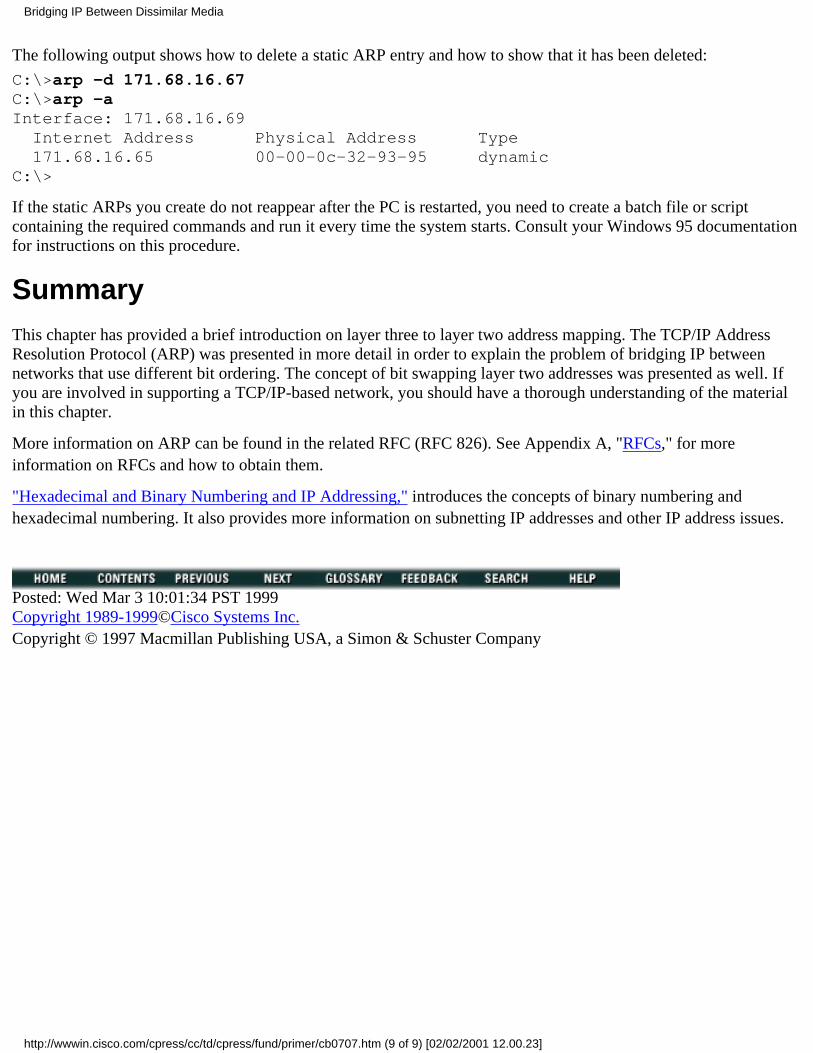
The following output shows how to delete a static ARP entry and how to show that it has been deleted:
C:\>arp -d 171.68.16.67C:\>arp -aInterface: 171.68.16.69 Internet Address Physical Address Type 171.68.16.65 00-00-0c-32-93-95 dynamicC:\>
If the static ARPs you create do not reappear after the PC is restarted, you need to create a batch file or scriptcontaining the required commands and run it every time the system starts. Consult your Windows 95 documentationfor instructions on this procedure.
SummaryThis chapter has provided a brief introduction on layer three to layer two address mapping. The TCP/IP AddressResolution Protocol (ARP) was presented in more detail in order to explain the problem of bridging IP betweennetworks that use different bit ordering. The concept of bit swapping layer two addresses was presented as well. Ifyou are involved in supporting a TCP/IP-based network, you should have a thorough understanding of the materialin this chapter.
More information on ARP can be found in the related RFC (RFC 826). See Appendix A, "RFCs," for moreinformation on RFCs and how to obtain them.
"Hexadecimal and Binary Numbering and IP Addressing," introduces the concepts of binary numbering andhexadecimal numbering. It also provides more information on subnetting IP addresses and other IP address issues.
Posted: Wed Mar 3 10:01:34 PST 1999Copyright 1989-1999©Cisco Systems Inc.Copyright © 1997 Macmillan Publishing USA, a Simon & Schuster Company
Bridging IP Between Dissimilar Media
http://wwwin.cisco.com/cpress/cc/td/cpress/fund/primer/cb0707.htm (9 of 9) [02/02/2001 12.00.23]

Table of Contents
Hexadecimal and Binary Numbering and IP Addressing
Binary Numbering Versus Decimal NumberingHexadecimal Numbering Versus Decimal NumberingIntroduction to the 32-Bit IP Address
Classes of AddressesDefault Subnet Masks for Class A, B, C, and D Addresses
Understanding Subnet Masks, Subnetting, and SupernettingDetermining What Subnet Is Being UsedThe Shorthand Subnet Mask IndicatorIntroduction to SupernettingCalculating Subnet and Host Combinations
Summary
Hexadecimal and Binary Numbering and IPAddressingThis chapter helps you understand the structure of IP addresses and how to use subnetting and supernetting, a newerconcept, to more effectively control major network address space. The chapter is broken into the following sections:
Binary numbering versus decimal numbering●
Hexadecimal numbering versus decimal numbering●
Introduction to the 32-bit IP address●
Understanding subnet masks, subnetting, and supernetting●
Binary Numbering Versus Decimal NumberingBinary numbering uses only 0s and 1s. It is a base-2 numbering system in which one is the largest digit that can be used inany position. This is the same as having nine be the largest number that can be used in any position in a decimal number.
Each digit in a binary number is multiplied by 2 to the power of the digit's position in the binary number, with the firstposition being the power of (0). Any number to the power of 0 is 1. Therefore, (1*(100))=1=(1*(20)).
Consider the binary number 1010. It can written in the more explicit form of 1*(23) + 0*(22) + 1*(21) + 0*(20). This isone way to convert a binary number to a decimal number. In this case, 1*(23) equals decimal 8, 0*(22) equals decimal 0,1*(21) equals decimal 2, and 0*(20) equals decimal 0, resulting in the following formula: 8+0+2+0=10. Therefore, 1010 inbinary is 10 in decimal format.
Compare the binary (base-2) number 1010 with the decimal (base-10) number 1010. You write out the base-10 numberusing the same system as the base-2 number, resulting in 1*(103) + 0*(102) + 1*(101) + 0*(100), which gives you theformula (1*1000) + (0*100) + (1*10) + (0*1)=1010. This is also written as 1010.
You now need to consider eight-digit numbers (bytes or octets) because this is the unit most commonly used by computer
Hexadecimal and Binary Numbering and IP Addressing
http://wwwin.cisco.com/cpress/cc/td/cpress/fund/primer/cb0708.htm (1 of 9) [02/02/2001 12.00.27]

addressing schemes. Extend the concept of powers and position discussed previously to add four more digits.
First, consider the binary number 10101010. You can write it out using the same system as before: 1*(27) + 0*(26) +1*(25) + 0*(24) + 1*(23) + 0*(22) + 1*(21) + 0*(20)=170 in decimal format. How do you arrive at this answer? Look at thefollowing method for writing out the same number:
1*(27) = 128
+ 0*(26) = 0
+ 1*(25) = 32
+ 0*(24) = 0
+ 1*(23) = 8
+ 0*(22) = 0
+ 1*(21) = 2
+ 0*(20) = 0
= 170
Some people prefer to think about octets in terms of the values represented by each position. The positions are 7, 6, 5, 4, 3,2, 1, and 0. These are the powers that the base is raised to for each position. For binary, the resulting values in decimalformat are 128, 64, 32, 16, 8, 4, 2, and 1. Once again, 27=128, 26=64, 25=32, 24=16, 23=8, 22=4, 21=2, and 20=1.
Compare this to the decimal values for the same eight positions using base 10: 10,000,000; 1,000,000; 100,000; 10,000;1,000; 100; 10; 1. Once again, 107=10,000,000; 106=1,000,000; 105=100,000; 104=10,000; 103=1,000; 102=100; 101=10;and 100=1.
Just as the decimal numbering system has a ten thousands place, a one thousands place, and a thousands place, the binarynumbering system has a 128 place, a 64 place, a 32 place, and so on.
Note One final note on binary octets: If every digit in an octet is set to 1, the resulting number in decimal format is 255.128+64+32+16+8+4+ 2+1=255. This is a key point to understand because it plays a significant part in IP addressing.
An easy system for changing decimal numbers into binary numbers uses iterative division, dividing by 2 until a remainderof 1 is achieved. You can convert 170 in decimal form to its binary equivalent. You start by dividing the number to beconverted (170) by 2. The result is divided by 2 again, while the remainder is written off to the side. Remainders arewritten from right to left.
170/2 = 85 R 0. Binary result so far 0.
85/2 = 42 R 1. Binary result so far 10.
42/2 = 21 R 0. Binary result so far 010.
21/2 = 10 R 1. Binary result so far 1010.
10/2 = 5 R 0. Binary result so far 01010.
5/2 = 2 R 1. Binary result so far 101010.
2/2 = 1 R 0. Binary result so far 0101010.
1/2 = 0 R 1. Binary result so far 10101010.
Hexadecimal and Binary Numbering and IP Addressing
http://wwwin.cisco.com/cpress/cc/td/cpress/fund/primer/cb0708.htm (2 of 9) [02/02/2001 12.00.27]
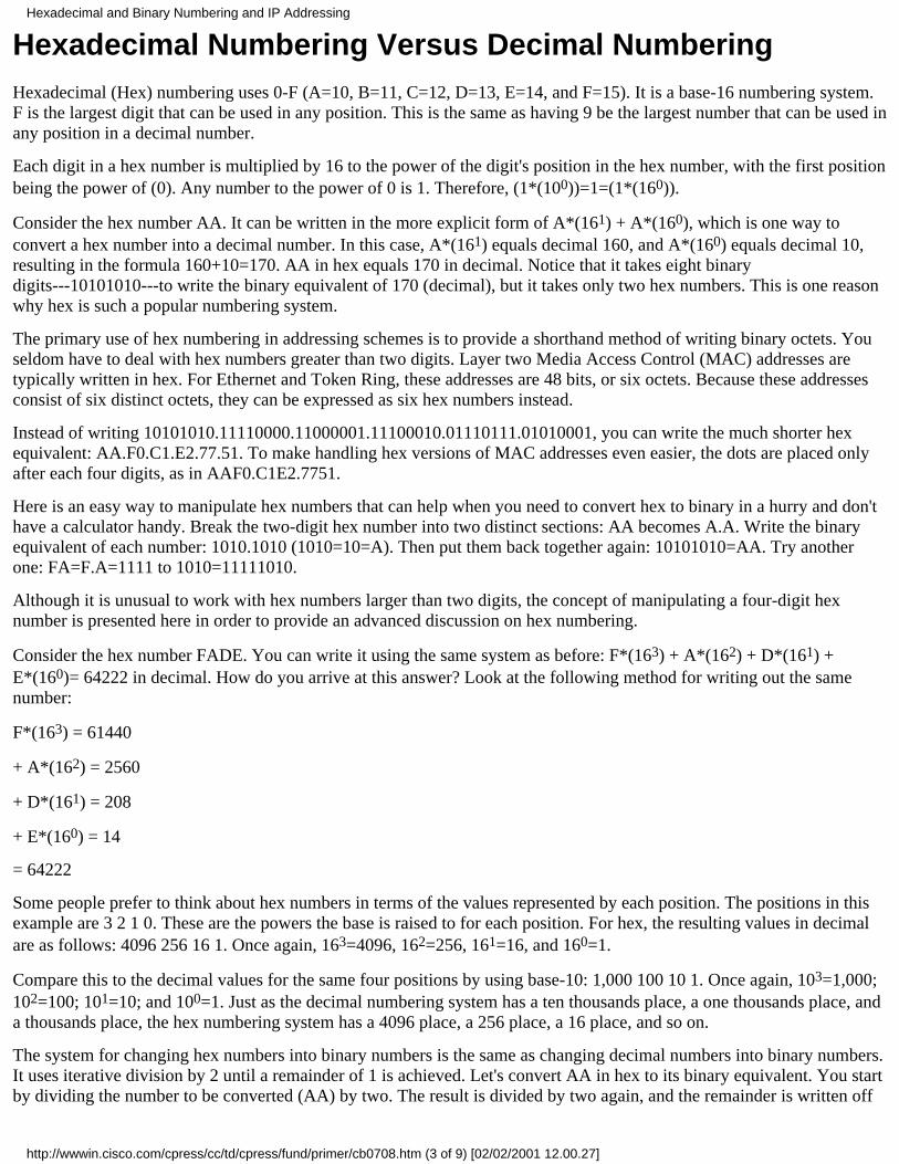
Hexadecimal Numbering Versus Decimal NumberingHexadecimal (Hex) numbering uses 0-F (A=10, B=11, C=12, D=13, E=14, and F=15). It is a base-16 numbering system.F is the largest digit that can be used in any position. This is the same as having 9 be the largest number that can be used inany position in a decimal number.
Each digit in a hex number is multiplied by 16 to the power of the digit's position in the hex number, with the first positionbeing the power of (0). Any number to the power of 0 is 1. Therefore, (1*(100))=1=(1*(160)).
Consider the hex number AA. It can be written in the more explicit form of A*(161) + A*(160), which is one way toconvert a hex number into a decimal number. In this case, A*(161) equals decimal 160, and A*(160) equals decimal 10,resulting in the formula 160+10=170. AA in hex equals 170 in decimal. Notice that it takes eight binarydigits---10101010---to write the binary equivalent of 170 (decimal), but it takes only two hex numbers. This is one reasonwhy hex is such a popular numbering system.
The primary use of hex numbering in addressing schemes is to provide a shorthand method of writing binary octets. Youseldom have to deal with hex numbers greater than two digits. Layer two Media Access Control (MAC) addresses aretypically written in hex. For Ethernet and Token Ring, these addresses are 48 bits, or six octets. Because these addressesconsist of six distinct octets, they can be expressed as six hex numbers instead.
Instead of writing 10101010.11110000.11000001.11100010.01110111.01010001, you can write the much shorter hexequivalent: AA.F0.C1.E2.77.51. To make handling hex versions of MAC addresses even easier, the dots are placed onlyafter each four digits, as in AAF0.C1E2.7751.
Here is an easy way to manipulate hex numbers that can help when you need to convert hex to binary in a hurry and don'thave a calculator handy. Break the two-digit hex number into two distinct sections: AA becomes A.A. Write the binaryequivalent of each number: 1010.1010 (1010=10=A). Then put them back together again: 10101010=AA. Try anotherone: FA=F.A=1111 to 1010=11111010.
Although it is unusual to work with hex numbers larger than two digits, the concept of manipulating a four-digit hexnumber is presented here in order to provide an advanced discussion on hex numbering.
Consider the hex number FADE. You can write it using the same system as before: F*(163) + A*(162) + D*(161) +E*(160)= 64222 in decimal. How do you arrive at this answer? Look at the following method for writing out the samenumber:
F*(163) = 61440
+ A*(162) = 2560
+ D*(161) = 208
+ E*(160) = 14
= 64222
Some people prefer to think about hex numbers in terms of the values represented by each position. The positions in thisexample are 3 2 1 0. These are the powers the base is raised to for each position. For hex, the resulting values in decimalare as follows: 4096 256 16 1. Once again, 163=4096, 162=256, 161=16, and 160=1.
Compare this to the decimal values for the same four positions by using base-10: 1,000 100 10 1. Once again, 103=1,000;102=100; 101=10; and 100=1. Just as the decimal numbering system has a ten thousands place, a one thousands place, anda thousands place, the hex numbering system has a 4096 place, a 256 place, a 16 place, and so on.
The system for changing hex numbers into binary numbers is the same as changing decimal numbers into binary numbers.It uses iterative division by 2 until a remainder of 1 is achieved. Let's convert AA in hex to its binary equivalent. You startby dividing the number to be converted (AA) by two. The result is divided by two again, and the remainder is written off
Hexadecimal and Binary Numbering and IP Addressing
http://wwwin.cisco.com/cpress/cc/td/cpress/fund/primer/cb0708.htm (3 of 9) [02/02/2001 12.00.27]

to the side. Remainders are written from right to left.
AA/2 = 55 R 0 Binary result so far 0.
55/2 = 2A R 1 Binary result so far 10.
2A/2 = 15 R 0 Binary result so far 010.
15/2 = A R 1 Binary result so far 1010.
A/2 = 5 R 0 Binary result so far 01010.
5/2 = 2 R 1 Binary result so far 101010.
2/2 = 1 R 0 Binary result so far 0101010.
1/2 = 0 R 1 Binary result so far 10101010.
You can do this again using the decimal equivalents of the hex numbers to make it easier to see what is going on:
170/2 = 85 R 0 Binary result so far 0.
85/2 = 42 R 1 Binary result so far 10.
42/2 = 21 R 0 Binary result so far 010.
21/2 = 10 R 1 Binary result so far 1010.
10/2 = 5 R 0 Binary result so far 01010.
5/2 = 2 R 1 Binary result so far 101010.
2/2 = 1 R 0 Binary result so far 0101010.
1/2 = 0 R 1 Binary result so far 10101010.
Introduction to the 32-Bit IP AddressAn IP address consists of four sets of octets (eight bits per octet), or 32 bits. IP addresses are typically written in a formatreferred to as dotted decimal format. In other words, the number base is decimal and the sections are denoted by dots (.). AClass B address representation is as follows: 10.1.23.19.
10. 1. 23. 19 (decimal)00001010.00000001.00010111.00010011 (binary)
10.1.23.19 is much easier to work with than its binary equivalent, 00001010.00000001.00010111.00010011. It isimportant to note that they both have the exact same meaning.
Classes of Addresses
These four octets are broken down to provide an addressing scheme that can provide for large and small networks.Although there are five different classes of networks (A to E), you will only be considering classes A to C. To differentiatebetween different classes of addresses, look at the first octet of the dotted-decimal address:
* Class A: 1 - 126 (e.g. 10.1.23.19) (0.0.0.0 and 127.0.0.0 are reserved)* Class B: 128-191 (e.g. 172.16.19.48) (128.0.0.0 and 191.255.0.0 are reserved)* Class C: 192-226 (e.g. 193.18.9.10) (192.0.0.0 and 223.255.255.0 are reserved)
Note The reserved addresses used in the section on IP address classes are commonly referred to as martian networks.Routing protocols such as RIP and IGRP running on IP connectivity devices, such as routers, should ignore routingadvertisements for martian networks. The reserved addresses given represent the minimum set of martian networks that
Hexadecimal and Binary Numbering and IP Addressing
http://wwwin.cisco.com/cpress/cc/td/cpress/fund/primer/cb0708.htm (4 of 9) [02/02/2001 12.00.27]
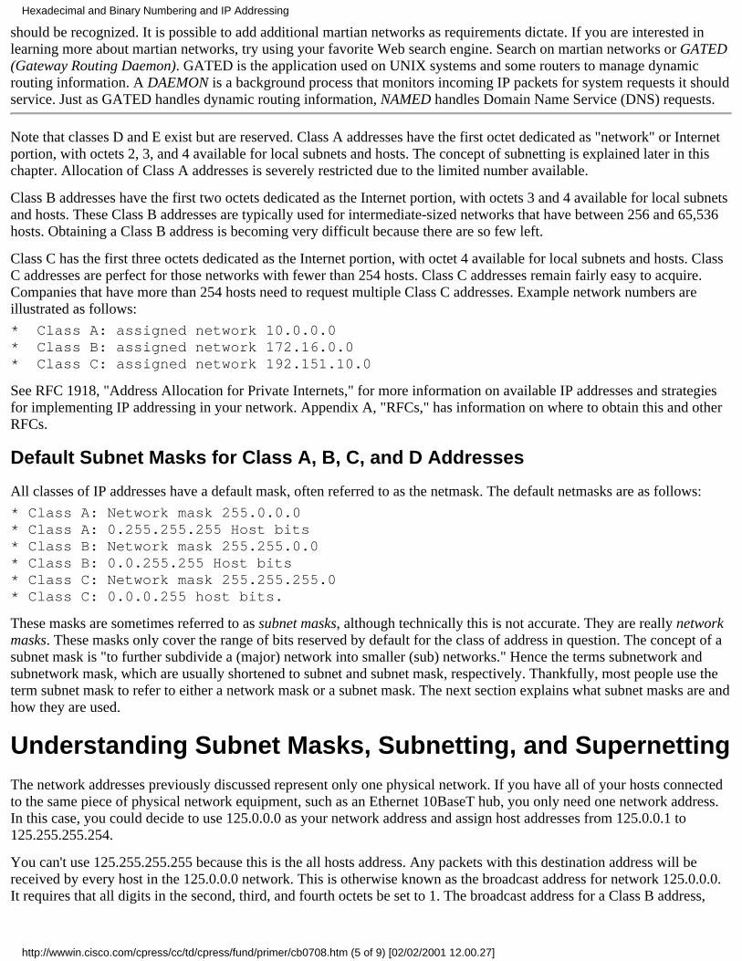
should be recognized. It is possible to add additional martian networks as requirements dictate. If you are interested inlearning more about martian networks, try using your favorite Web search engine. Search on martian networks or GATED(Gateway Routing Daemon). GATED is the application used on UNIX systems and some routers to manage dynamicrouting information. A DAEMON is a background process that monitors incoming IP packets for system requests it shouldservice. Just as GATED handles dynamic routing information, NAMED handles Domain Name Service (DNS) requests.
Note that classes D and E exist but are reserved. Class A addresses have the first octet dedicated as "network" or Internetportion, with octets 2, 3, and 4 available for local subnets and hosts. The concept of subnetting is explained later in thischapter. Allocation of Class A addresses is severely restricted due to the limited number available.
Class B addresses have the first two octets dedicated as the Internet portion, with octets 3 and 4 available for local subnetsand hosts. These Class B addresses are typically used for intermediate-sized networks that have between 256 and 65,536hosts. Obtaining a Class B address is becoming very difficult because there are so few left.
Class C has the first three octets dedicated as the Internet portion, with octet 4 available for local subnets and hosts. ClassC addresses are perfect for those networks with fewer than 254 hosts. Class C addresses remain fairly easy to acquire.Companies that have more than 254 hosts need to request multiple Class C addresses. Example network numbers areillustrated as follows:
* Class A: assigned network 10.0.0.0* Class B: assigned network 172.16.0.0* Class C: assigned network 192.151.10.0
See RFC 1918, "Address Allocation for Private Internets," for more information on available IP addresses and strategiesfor implementing IP addressing in your network. Appendix A, "RFCs," has information on where to obtain this and otherRFCs.
Default Subnet Masks for Class A, B, C, and D Addresses
All classes of IP addresses have a default mask, often referred to as the netmask. The default netmasks are as follows:
* Class A: Network mask 255.0.0.0 * Class A: 0.255.255.255 Host bits* Class B: Network mask 255.255.0.0* Class B: 0.0.255.255 Host bits* Class C: Network mask 255.255.255.0* Class C: 0.0.0.255 host bits.
These masks are sometimes referred to as subnet masks, although technically this is not accurate. They are really networkmasks. These masks only cover the range of bits reserved by default for the class of address in question. The concept of asubnet mask is "to further subdivide a (major) network into smaller (sub) networks." Hence the terms subnetwork andsubnetwork mask, which are usually shortened to subnet and subnet mask, respectively. Thankfully, most people use theterm subnet mask to refer to either a network mask or a subnet mask. The next section explains what subnet masks are andhow they are used.
Understanding Subnet Masks, Subnetting, and SupernettingThe network addresses previously discussed represent only one physical network. If you have all of your hosts connectedto the same piece of physical network equipment, such as an Ethernet 10BaseT hub, you only need one network address.In this case, you could decide to use 125.0.0.0 as your network address and assign host addresses from 125.0.0.1 to125.255.255.254.
You can't use 125.255.255.255 because this is the all hosts address. Any packets with this destination address will bereceived by every host in the 125.0.0.0 network. This is otherwise known as the broadcast address for network 125.0.0.0.It requires that all digits in the second, third, and fourth octets be set to 1. The broadcast address for a Class B address,
Hexadecimal and Binary Numbering and IP Addressing
http://wwwin.cisco.com/cpress/cc/td/cpress/fund/primer/cb0708.htm (5 of 9) [02/02/2001 12.00.27]

such as 171.54.0.0, would be 171.54.255.255. The broadcast address for a Class C network, such as 220.34.145.0, wouldbe 220.34.145.255.
If you have hosts in two or more locations, and the locations are connected by a router, you cannot use the 125.0.0.0address in more than one location. This is because systems running IP consider the portion of the address covered by thenetmask to be the "network" address and consider the remainder of the address to be the "host" portion. Each networkmust be unique because that is how systems such as routers---which connect physical networks together and provide layerthree connectivity---determine where the IP networks are located.
Consider a router with two Ethernet ports, 0 and 1. If the IP address on port 0 were 125.0.0.1 and the IP address on 1 were125.0.0.2, the router would not be able to determine which interface a host with the IP address of 125.0.0.3 was reachableover using only layer three information. This is because the router only stores the network portion of the address in itsrouting table---in this case, 125.0.0.0.
The routing table is the database the router uses to keep track of all available networks. Looking at a packet destined for125.0.0.3, the router would discover that it is a host system on the 125.0.0.0 network. The router would then query itsrouting table to determine which interface it knows about network 125.0.0.0 over. In this example, it would discover thatboth Ethernet 0 and Ethernet 1 have connections to 125.0.0.0. The only logical conclusion the router could reach is thatboth interfaces are actually connected to the same physical network. In this case, the router should be able to pick eitherinterface to forward the packet over.
The other choice is to send two copies of the packet---one over each interface. Sending duplicate packets is usually not agood idea. They waste processing power on the system receiving them, so the router is likely to randomly select one of theinterfaces. If 125.0.0.3 is connected to the physical network the router selects, the packet is received. If it is not, the packetis not received.
With the exception of parallel WAN links using HDLC encapsulation, Cisco routers do not allow the same networkaddress to be applied to more than one interface. This applies to subnets as well.
Think about telephone area codes in the U.S. phone system. Each area code must be unique. Otherwise, the phone systemwould not be able to deliver the calls successfully.
However, the host portions of an address can be the same on different networks. Just as the phone system allows fornumbers such as 408 555 1212 and 650 555 1212, IP networks allow for addresses such as 10.1.2.3 255.0.0.0 and 11.1.2.3255.0.0.0. The phone system routes the call based on the area code and lets the local office keep track of its availablenumbers (telephones). The routers in an IP network route IP packets based on their network addresses and let the finalrouter in the path deliver the packet to its final destination (IP end system).
The two solutions to this problem are as follows:
Select a different network address for each location. Use the default network mask for each address. In this case,you could use 126.0.0.0 and 130.0.0 for the next two locations. Remember that 127.0.0.0 and 128.0.0.0 arereserved.
●
Use subnetting. In this case, you need to come up with what is known as a subnet mask. What you are basicallydoing is creating subnetworks from a major network.
●
Note The term major network or major net is simply a reference to the default network portion of an IP address based onits class. The major net of the Class A host address 125.0.0.1 is 125.0.0.0. (Class A networks reserve only the first octet.)The major net of the Class B host address 168.92.0.1 is 168.92.0.0. (Class B networks reserve the first and second octets.)
Because a Class A address uses the first octet as the network portion and the final three octets as host bits, the only way tocreate additional networks from the original network address is to somehow steal some of the hosts bits. Keep in mind thatin the previous example, the "125" portion of address 125.0.0.1 was fixed. If you were to change it to, say, 126.0.0.1, youwould use a completely different Class A address, which is not your goal. Your goal is to create more networks from theoriginal 125.0.0.0 network.
If you understand that the default mask of 255.0.0.0 for a Class A indicates that the first octet is fixed and that the
Hexadecimal and Binary Numbering and IP Addressing
http://wwwin.cisco.com/cpress/cc/td/cpress/fund/primer/cb0708.htm (6 of 9) [02/02/2001 12.00.27]
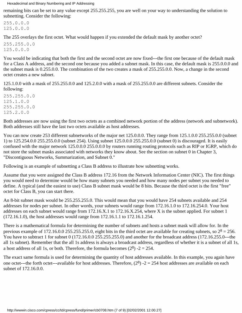
remaining bits can be set to any value except 255.255.255, you are well on your way to understanding the solution tosubnetting. Consider the following:
255.0.0.0125.0.0.0
The 255 overlays the first octet. What would happen if you extended the default mask by another octet?
255.255.0.0125.0.0.0
You would be indicating that both the first and the second octet are now fixed---the first one because of the default maskfor a Class A address, and the second one because you added a subnet mask. In this case, the default mask is 255.0.0.0 andthe subnet mask is 0.255.0.0. The combination of the two creates a mask of 255.255.0.0. Now, a change in the secondoctet creates a new subnet.
125.1.0.0 with a mask of 255.255.0.0 and 125.2.0.0 with a mask of 255.255.0.0 are different subnets. Consider thefollowing:
255.255.0.0125.1.0.0255.255.0.0125.2.0.0
Both addresses are now using the first two octets as a combined network portion of the address (network and subnetwork).Both addresses still have the last two octets available as host addresses.
You can now create 253 different subnetworks of the major net 125.0.0.0. They range from 125.1.0.0 255.255.0.0 (subnet1) to 125.254.0.0 255.255.0.0 (subnet 254). Using subnet 125.0.0.0 255.255.0.0 (subnet 0) is discouraged. It is easilyconfused with the major network 125.0.0.0 255.0.0.0 by routers running routing protocols such as RIP or IGRP, which donot store the subnet masks associated with networks they know about. See the section on subnet 0 in Chapter 3,"Discontiguous Networks, Summarization, and Subnet 0."
Following is an example of subnetting a Class B address to illustrate how subnetting works.
Assume that you were assigned the Class B address 172.16 from the Network Information Center (NIC). The first thingsyou would need to determine would be how many subnets you needed and how many nodes per subnet you needed todefine. A typical (and the easiest to use) Class B subnet mask would be 8 bits. Because the third octet is the first "free"octet for Class B, you can start there.
An 8-bit subnet mask would be 255.255.255.0. This would mean that you would have 254 subnets available and 254addresses for nodes per subnet. In other words, your subnets would range from 172.16.1.0 to 172.16.254.0. Your hostaddresses on each subnet would range from 172.16.X.1 to 172.16.X.254, where X is the subnet applied. For subnet 1(172.16.1.0), the host addresses would range from 172.16.1.1 to 172.16.1.254.
There is a mathematical formula for determining the number of subnets and hosts a subnet mask will allow for. In theprevious example of 172.16.0.0 255.255.255.0, eight bits in the third octet are available for creating subnets, so 28 = 256.You have to subtract 1 for subnet 0 (172.16.0.0 255.255.255.0) and another for the broadcast address (172.16.255.0---theall 1s subnet). Remember that the all 1s address is always a broadcast address, regardless of whether it is a subnet of all 1s,a host address of all 1s, or both. Therefore, the formula becomes (28) -2 = 254.
The exact same formula is used for determining the quantity of host addresses available. In this example, you again haveone octet---the forth octet---available for host addresses. Therefore, (28) -2 = 254 host addresses are available on eachsubnet of 172.16.0.0.
Hexadecimal and Binary Numbering and IP Addressing
http://wwwin.cisco.com/cpress/cc/td/cpress/fund/primer/cb0708.htm (7 of 9) [02/02/2001 12.00.27]

Determining What Subnet Is Being Used
Sometimes it is not as easy as the previous example may have led you to believe to determine which subnet a host addressis part of. Subnets do not have to be created on octet boundaries. Consider the following perfectly valid host address:
172.16.32.1 255.255.240.0
This is not a host on the 32nd subnet of major net 172.16.0.0. As you will discover in a moment, it is the third subnet of172.16.0.0 when using a mask of 255.255.240.0. However, it is still fairly easy to determine that a host address such as172.16.32.1 is part of subnet 172.16.32.0. Consider the following host address:
172.16.44.1 255.255.240.0
What subnet is it part of? Unlike the previous example, in which any bit changed in the third octet represented a newsubnet, this example has only reserved the first four bits of the third octet. This allows for (24) - 2 = 14 subnets and (212) -2 = 4094 hosts.
Look at the address and mask in binary:
11111111.11111111.11110000.00000000 (mask)10101100.00010000.00101100.00000001 (host address)
Notice that in the third octet of the host address, only one bit is set to one in the bits covered by the subnet mask.Remember that the subnet mask reserves bits for creating unique subnets. Because the remaining three bits that are set to 1in the third octet of the host address are outside of the reserved bits, they must be host bits. Therefore, host address172.16.44.1 is also in subnet 0.0.32.0 of the major net 172.16.0.0.
A certain logical (Boolean) formula can be used to determine what subnet a host address is part of. It requires a logicalAND operation. Performing an AND operation means that any time you AND a 0 value to another 0 or a 1 value, theresult is 0. Only a 1 ANDed with another 1 value will result in a 1 value. This is illustrated as follows:
0 0 1 0 1 1 - - - 0 0 1
Start by representing the bits in binary. You can drop the 1 in the last octet of the host address because the mask stopshalfway through the third octet. Therefore, any bits set in the fourth octet must be host bits, not subnet bits.
172.16.44.0 = 10101100.00010000.00101100.00000000 255.255.240.0 = 11111111.11111111.11110000.00000000Results of AND = 10101100.00010000.00100000.00000000
The resulting value is 172.16.32.0. Therefore, this is subnet 0.0.32.0 of the major net address 172.16.0.0.
The Shorthand Subnet Mask Indicator
Many TCP/IP devices have adopted a shorthand method for indicating the subnet mask associated with a network address.The format is 171.68.0.0/16. This is the shorthand version of 171.68.0.0 255.255.0.0. The /16 indicates that 16 bits arereserved for the subnet mask. 171.68.0.0/24 is shorthand for 171.68.0.0 255.255.255.0. As a final example, consider theClass C address 193.65.200.0/30, which is shorthand for 193.65.200.0 255.255.255.252. As you can see, this is a mucheasier method for representing IP network addresses and their associated masks.
Note The /16 is also used with the term prefix, as in "the address 171.68.0.0/16 has a 16-bit prefix." Prefix is a shorthandway of referring to the number of bits in the address that are covered by the associated subnet mask. A non-subnettedClass C address has a 24-bit prefix by default. A subnetted Class C address with a mask of 255.255.255.240 has a /28 bitsubnet mask and a 28-bit prefix.
Hexadecimal and Binary Numbering and IP Addressing
http://wwwin.cisco.com/cpress/cc/td/cpress/fund/primer/cb0708.htm (8 of 9) [02/02/2001 12.00.27]

Introduction to Supernetting
Supernetting is another term that anyone supporting an IP network should be familiar with. It is almost the opposite ofsubnetting. Subnetting refers to making additional smaller (sub) networks out of a major network. Supernetting, on theother hand, refers to making one large (super) network out of two or more smaller networks. The smaller networks can bemajor nets, such as 220.100.100.0/24, or subnets, such as 220.67.87.0/32.
Consider a company (Catco, Inc.) that has been granted the following registered Class C addresses: 220.220.1.0 through220.220.255.0. Assume that Catco has assigned (used) 220.220.1.0 through 220.220.100.0. Catco does not need toadvertise the entire list of 100 individual Class C addresses to the Internet. Instead, Catco can supernet the addresses to ashorter prefix: 220.220.0.0/16. This results in a 99 percent reduction in the number of routes that need to be advertised tothe Internet. Full connectivity from the Internet to the 100 assigned Class C addresses is still possible because Catco hascontrol of every possible network with the 16-bit supernet prefix of 220.220.0.0 (220.220.1.0, 220.220.2.0, . . . ,220.220.254.0 and 220.220.255.0).
Note You must configure the global command ip classless on a Cisco router in order to implement supernetting.
Supernetting is part of the broader concept of classless interdomain routing (CIDR). See Appendix A for a list of RFCsthat provide more information on CIDR and supernetting.
This has been an intentionally brief introduction to the concept of supernetting. If you want to implement supernetting,you should consult the relevant RFCs. The book Internet Routing Architectures by Bassam Halabi, published by CiscoPress (ISBN 1-56205-652-2), is another excellent source of information on this subject.
Calculating Subnet and Host Combinations
Cisco Systems has a tool on CCO that makes subnetting much easier. Log on to CCO with your username and passwordand then access the following URL: http://www.cisco.com/ techtools/ip_addr.html.
The Net3 Group has a Windows tool that can help you perform subnet and hosts calculations. See the URLhttp://www.net3group.com/ipcalc.html-ssi or search Net3's main home page at http://www.net3group.com.
SummaryThis chapter has provided a brief introduction on binary and hexadecimal numbers. IP address concepts and issues werepresented as well. If you are involved in supporting an IP-based network, you should have a thorough understanding ofthis material.
Appendix A contains a list of RFCs that provide additional information on the concepts presented in this book.
Posted: Wed Mar 3 10:02:26 PST 1999Copyright 1989-1999©Cisco Systems Inc.Copyright © 1997 Macmillan Publishing USA, a Simon & Schuster Company
Hexadecimal and Binary Numbering and IP Addressing
http://wwwin.cisco.com/cpress/cc/td/cpress/fund/primer/cb0708.htm (9 of 9) [02/02/2001 12.00.27]

Table of Contents
RFCs
How RFCs WorkRFCs Recommended for Further Study
RFC 2235: Hobbes' Internet TimelineRFC 2200: Internet Official Protocol StandardsRFC 2151: A Primer on Internet and TCP/IP Tools and UtilitiesRFC 2101: IPv4 Address Behavior TodayRFC 2031: IETF-ISOC RelationshipRFC 2028: The Organizations Involved in the IETF Standards ProcessRFC 2027: IAB and IESG Selection, Confirmation, and Recall Process: Operation of theNominating and Recall CommitteesRFC 2026: The Internet Standards Process: Revision 3RFC 2008: Implications of Various Address Allocation Policies for Internet RoutingRFC 1935: What Is the Internet, Anyway?RFC 1925: The Twelve Networking TruthsRFC 1923: RIPv1 Applicability Statement for Historic StatusRFC 1918: Address Allocation for Private InternetsRFC 1917: An Appeal to the Internet Community to Return Unused IP Networks (Prefixes)to the IANARFC 1878: Variable Length Subnet Table for IPv4RFC 1812: Requirements for IP Version 4 RoutersRFC 1631: The IP Network Address Translator (NAT)RFC 1601: Charter of the Internet Architecture Board (IAB)RFC 1580: Guide to Network Resource ToolsRFC 1393: Traceroute Using an IP OptionRFC 1256: ICMP Router Discovery MessagesRFC 1180: A TCP/IP TutorialRFC 1178: Choosing a Name for Your ComputerRFC 1149: A Standard for the Transmission of IP Datagrams on Avian CarriersRFC 1058: Routing Information ProtocolRFC 826: An Ethernet Address Resolution ProtocolRFC 1700: Assigned NumbersRFC 1534: BOOTPRFC 2283, RFC 1966, RFC 1965, RFC 1774, RFC 1773, RFC 1772, RFC 1771, RFC 1745:Border Gateway Protocol V4 (BGP4)RFC 1817, RFC 1520, RFC 1519, RFC 1518, RFC 1517: Classless Interdomain Routing(CIDR)
Appendix A: RFCs
http://wwwin.cisco.com/cpress/cc/td/cpress/fund/primer/cb07ax.htm (1 of 9) [02/02/2001 12.00.31]

RFC 2132, RFC 2131, RFC 1534: Dynamic Host Configuration Protocol (DHCP)RFC 2308, RFC 2230, RFC 2219, RFC 2182, RFC 2181, RFC 2136, RFC 2052, RFC 1996,RFC 1995, RFC 1912, RFC 1794, RFC 1713: Domain Name System (DNS)RFC 2178, RFC 1745, RFC 1587, RFC 1586, RFC 1585, RFC 1584: Open Shortest PathFirst (OSPF)RFC 1931, RFC 1293: Reverse Address Resolution Protocol (RARP) Inverse RARPRFC 2092, RFC 2091, RFC 1723, RFC 1722, RFC 1721, RFC 1582, RFC 1581: RIPRFC 2072, RFC 2071: Router RenumberingRFC 2001: TCP/IP (TCP) Slow StartRFC 1470: TCP/IP Debugging Tools
Summary
RFCsThis appendix contains titles and brief introductions for the RFCs referenced in this book. It also containssome RFCs that are useful for people just getting started in TCP/IP-based internetworking and theInternet. Some of these RFCs explain the standards bodies and their policies. Others explain fundamentalconcepts that are useful to understand. A couple---such as RFC 1149---show the humorous side of theRFC world.
A full index of RFCs can be found at the following URL: http://www.cis.ohio-state.edu/htbin/rfc/rfc-index.html. If this URL is unavailable for any reason, search with the keyword RFC in yourfavorite Web search engine.
How RFCs WorkRFCs are numbered based on when they were written, not by title or content. Occasionally, a group ofrelated RFCs are all updated and posted at the same time. In this case, they are numbered sequentially.The simplest way to find an RFC on a particular subject is to open the RFC index in a word processor ora Web browser and search for a keyword.
For example, to find all RFCs related to RIP, search with the keyword RIP. Be sure to make your searchcase sensitive. Otherwise, you will get hits on words such as "postscript." Because the RFCs are indexedin the order in which they are written, you can search from the top of the index to find the latest versionsfirst.
Whenever you are reading an RFC, look for a statement that says (Obsoleted by RFCxxx). If you see thisstatement, you are reading an outdated copy. When in doubt, always refer to a recent copy of the RFCindex. It always indicates whether a newer revision of an RFC is available.
Appendix A: RFCs
http://wwwin.cisco.com/cpress/cc/td/cpress/fund/primer/cb07ax.htm (2 of 9) [02/02/2001 12.00.31]
RFCs Recommended for Further StudyThe RFCs selected for this list were chosen in a highly subjective and arbitrary fashion. Note, forexample, that entire topics--- such as the Simple Network Management Protocol (SNMP) and the PostOffice Protocol (POP3)---have been omitted. Clearly, some topics had to be left out. Otherwise, thisappendix would have been a rewrite of the index itself. RFCs that would help you build a solid technicalfoundation, as well as the RFCs that explained the inner workings of the Internet standards bodies, areincluded.
Note Consult the RFC index for the latest versions of these RFCs before you start studying those listedhere. These numbers become outdated very quickly.
RFC 2235: Hobbes' Internet Timeline
This RFC provides a history of the major events that shaped the Internet into what it is today.
RFC 2200: Internet Official Protocol Standards
This RFC covers some of the processes involved in creating RFCs. It also explains some of the termsfound in RFCs and their usage. This is a "must read" for anyone involved in supporting IP networks.
RFC 2151: A Primer on Internet and TCP/IP Tools and Utilities
This name is pretty self-explanatory. RFC 2151 is an introduction to some of the fundamental tools andutilities available. Traceroute, PING, Finger, and others are covered. This is another "must read."
RFC 2101: IPv4 Address Behavior Today
This RFC clarifies the current interpretation of the IP V4 32-bit IP address space. It also provides somebackground on IP V6.
RFC 2031: IETF-ISOC Relationship
This RFC explains the relationship between the IETF and the Internet Society.
RFC 2028: The Organizations Involved in the IETF StandardsProcess
This is pretty much what it says it is---an explanation of the organizations involved in the IETF standardsprocess.
Appendix A: RFCs
http://wwwin.cisco.com/cpress/cc/td/cpress/fund/primer/cb07ax.htm (3 of 9) [02/02/2001 12.00.31]

RFC 2027: IAB and IESG Selection, Confirmation, and RecallProcess: Operation of the Nominating and Recall Committees
Again, this is pretty self-explanatory; it's an introduction to the process of selecting members for, andmanaging the membership of, the IAB and IESG.
RFC 2026: The Internet Standards Process: Revision 3
This is another RFC that explains RFC processes and other background information.
RFC 2008: Implications of Various Address Allocation Policies forInternet Routing
This RFC discusses some of the older policies for allocating IP address space. It suggests ways they canbe changed to reflect the Internet changes that have occurred since they were originally drafted.
RFC 1935: What Is the Internet, Anyway?
An informational RFC discussing the Internet and what it means to different people and organizations.
RFC 1925: The Twelve Networking Truths
This is a humorous RFC about life and networking.
RFC 1923: RIPv1 Applicability Statement for Historic Status
This RFC discusses the current status of RIP V1 (RFC 1058) and some of its limitations. Anyone runninga network with RIP V1 should read this.
RFC 1918: Address Allocation for Private Internets
This RFC provides background on the allocation of IP addresses for private Internets. It also providesimplementation guidelines for companies that want to implement IP but do not want full connectivity tothe Internet. This is a "must read" for anyone involved in supporting an IP network.
RFC 1917: An Appeal to the Internet Community to Return Unused IPNetworks (Prefixes) to the IANA
This RFC discusses the limited amount of IP addresses available for allocation. It also explains howcompanies that have addresses they no longer require can return them.
Appendix A: RFCs
http://wwwin.cisco.com/cpress/cc/td/cpress/fund/primer/cb07ax.htm (4 of 9) [02/02/2001 12.00.31]
RFC 1878: Variable Length Subnet Table for IPv4
This is a useful table of the various subnets that can be derived from the 32-bit IP address space.
RFC 1812: Requirements for IP Version 4 Routers
This RFC explains some of the functions that routers must perform when routing IP V4. This is a "mustread" for anyone involved in supporting an IP network that uses routers.
RFC 1631: The IP Network Address Translator (NAT)
This RFC explains the function of IP address translation and some of the requirements that must be metby a device implementing NAT. This is a "must read" for anyone involved in supporting an IP networkthat uses NAT when accessing the Internet.
RFC 1601: Charter of the Internet Architecture Board (IAB)
This is pretty self-explanatory; it is the charter of the IAB. Useful reading for anyone interested in thefunction of the IAB.
RFC 1580: Guide to Network Resource Tools
Similar to RFC 2151 in intent but not in content. This is more focused on information-finding tools, suchas Gopher, WAIS, and USENET. This is a "must read" for anyone using the Internet to find ordisseminate information.
RFC 1393: Traceroute Using an IP Option
This RFC provides background on the Traceroute utility. It also suggests some enhancements. This isuseful reading for those responsible for troubleshooting IP network problems.
RFC 1256: ICMP Router Discovery Messages
This RFC explains IRDP and discusses how IP systems can use it to find and use IP gateways (routers)off of their local network. Some third-party TCP/IP stacks for Windows 95 and Windows NT supportIRDP. SUN Solaris 2.5 does as well. Those exploring how to enable hosts to use multiple local gatewaysshould read this.
RFC 1180: A TCP/IP Tutorial
This RFC is a solid introduction to the TCP/IP protocol suite. It discusses the multiplexing of variousapplications over TCP and UDP. It also explains some related applications, such as Telnet and FTP. Thisis a "must read" for anybody just getting started in implementing an IP-based network. Experienced IPsupport engineers may find some new information as well.
Appendix A: RFCs
http://wwwin.cisco.com/cpress/cc/td/cpress/fund/primer/cb07ax.htm (5 of 9) [02/02/2001 12.00.31]
RFC 1178: Choosing a Name for Your Computer
This RFC covers some of the pitfalls of using inappropriate computer names and suggests some namingstrategies.
RFC 1149: A Standard for the Transmission of IP Datagrams onAvian Carriers
This is another humorous RFC.
RFC 1058: Routing Information Protocol
This is "the" RFC for RIP V1. It is a "must read" for supporters of IP networks with routers because thisis where it all started.
RFC 826: An Ethernet Address Resolution Protocol
This is the RFC on ARP. This is a "must read" for those involved in supporting IP networks.
RFC 1700: Assigned Numbers
This RFC contains references to the registered numbers that are assigned for various functions---such asTCP Port numbers for applications such as Telnet (23). Those involved in internetworking to any degreeshould be familiar with the material contained in this RFC.
RFC 1534: BOOTP
This RFC explains how certain TCP/IP configuration parameters, such as IP addresses, default gateways,and DNS servers, are passed from servers to workstations while the workstations are booting up. Thisallows network administrators to centralize the administration of this information. BOOTP has beensuperseded by the Dynamic Host Configuration Protocol (DHCP), which is referenced later in thisappendix.
RFC 2283, RFC 1966, RFC 1965, RFC 1774, RFC 1773, RFC 1772, RFC1771, RFC 1745: Border Gateway Protocol V4 (BGP4)
BGP4 is the latest version of this protocol. It specifies how routing information is passed betweenautonomous systems. Autonomous systems are groups of networks (which are typically very large) underthe control of a single organization or a group of cooperating organizations. Internet Service Providers(ISPs) that control the backbone of the Internet typically have their own autonomous systems. ISPs useBGP to link these autonomous systems to other ISPs' autonomous systems.
For more information on this subject, see Internet Routing Architectures by Bassam Halabi, published byCisco Press (ISBN 1-56205-652-2).
Appendix A: RFCs
http://wwwin.cisco.com/cpress/cc/td/cpress/fund/primer/cb07ax.htm (6 of 9) [02/02/2001 12.00.31]

RFC 1817, RFC 1520, RFC 1519, RFC 1518, RFC 1517: ClasslessInterdomain Routing (CIDR)
CIDR replaces the standard network masks applied to classes of IP addresses. For example, instead ofusing a mask such as 255.255.0.0 for network 171.68.0.0, a mask of 255.0.0.0 could be applied. Thiswould shorten the prefix of 171.68.0.0 to 171.0.0.0. If all of the networks that have 171 as their first octetwere under the control of a single autonomous system, the autonomous system managers could limit theiradvertisements to other autonomous systems to an 8-bit prefix.
Instead of sending 16-bit prefixes, such as 171.1.0.0, 171.2.0.0, 171.2.0.0, and 171.253.0.0, to anadjacent autonomous system, the manager can just send 171.0.0.0. Because there are 254 possible 16-bitprefixes starting with 171.0.0.0, advertising can be saved on up to 253 networks (you still have toadvertise 171.0.0.0), depending on how many of the available 171.0.0.0 networks are actually assigned.
The application of CIDR in the Internet has greatly reduced the numbers or routes (networks) that needto be advertised between and within autonomous systems.
RFC 2132, RFC 2131, RFC 1534: Dynamic Host ConfigurationProtocol (DHCP)
This RFC explains how certain TCP/IP configuration parameters, such as IP addresses, default gateways,and DNS servers, are passed from servers to workstations while the workstations are booting up. Thisallows network administrators to centralize the administration of this information. DHCP supersedesBOOTP, which was referenced previously.
RFC 2308, RFC 2230, RFC 2219, RFC 2182, RFC 2181, RFC 2136, RFC2052, RFC 1996, RFC 1995, RFC 1912, RFC 1794, RFC 1713: DomainName System (DNS)
This is the application that allows IP hosts to be referenced by names instead of explicit IP addresses. Forinstance, instead of entering c:\ftp 192.31.7.130 to start a Windows FTP session to Cisco's FTP site, youcan enter c:\ftp ftp.cisco.com.
If your PC's DNS server(s) is configured properly, your PC sends a DNS query to its DNS server(s) (itcan have more than one in case one fails) requesting the IP address associated with the system nameftp.cisco.com. After the reply is received, the FTP application uses the IP address it contains(192.31.7.130) to establish an FTP session.
RFC 2178, RFC 1745, RFC 1587, RFC 1586, RFC 1585, RFC 1584:Open Shortest Path First (OSPF)
These are the latest RFCs containing information on OSPF. OSPF is an open (not proprietary) standard.It is what is commonly known as an Interior Gateway Protocol (IGP). IGPs are typically used withinautonomous systems. IGP was created to overcome some of the significant limitations of the RoutingInformation Protocol V1 (RIP), such as lack of VLSM support and lack of discontiguous network
Appendix A: RFCs
http://wwwin.cisco.com/cpress/cc/td/cpress/fund/primer/cb07ax.htm (7 of 9) [02/02/2001 12.00.31]

support.
RFC 1931, RFC 1293: Reverse Address Resolution Protocol (RARP)Inverse RARP
These protocols perform the opposite function of the Address Resolution Protocol (ARP). ARP mapslayer three IP addresses to layer two MAC addresses. RARP, on the other hand, maps layer two MACaddresses to layer three IP addresses.
RFC 2092, RFC 2091, RFC 1723, RFC 1722, RFC 1721, RFC 1582, RFC1581: RIP
RIP V1 was one of the original IP routing protocols. RIP V2, which is now available on many TCP/IPsystems, overcomes some of the significant limitations of RIPV1, such as lack of VLSM support andlack of discontiguous network support. The RIP V1 protocol specification (RFC 1058) is provided in theprevious section. The other RFCs refer to RIP V2 and other RIP enhancements.
RFC 2072, RFC 2071: Router Renumbering
These informational RFCs explain the concept of renumbering IP networks and indicate when this maybe necessary.
RFC 2001: TCP/IP (TCP) Slow Start
TCP is the connection-oriented transport layer protocol in the TCP/IP protocol suite. It has flow controland error correction built in. It is used by TCP/IP applications, such as Telnet and FTP.
The TCP Slow Start algorithm forces a new TCP session to assume there is congestion on the network.This results in using a smaller packet size, a smaller window size (number of outstanding,unacknowledged packets), and a longer timeout (how long TCP will wait for acknowledgments beforeassuming a packet has been lost).
After the session is established, TCP starts increasing the packet size and the window size, whiledecreasing the timeout period. When TCP determines that the maximum values have been reached (thetimeout period starts to expire for some packets), it reduces the packet sizes and the window, whileincreasing the timeout period. However, these numbers are not immediately dropped to their originalSlow Start values.
RFC 1470: TCP/IP Debugging Tools
This RFC has valuable information on many tools and techniques for troubleshooting TCP/IP networkingproblems.
Appendix A: RFCs
http://wwwin.cisco.com/cpress/cc/td/cpress/fund/primer/cb07ax.htm (8 of 9) [02/02/2001 12.00.31]

SummaryThis appendix has provided information on obtaining and using RFCs. RFCs are the lifeblood of theInternet. Nothing happens without them. They represent the conception of new ideas (proposals). Theytrack the ideas through their gestation period (the ratification process) and finally document their birth(as an Internet standard).
After a standard has been established, RFCs track their evolution as well. Anybody supporting an IPnetwork should check out the RFC index at least twice a year to look for emerging standards, as well asnewer versions of RFCs for applicable technologies.
Posted: Wed Mar 3 10:02:51 PST 1999Copyright 1989-1999©Cisco Systems Inc.Copyright © 1997 Macmillan Publishing USA, a Simon & Schuster Company
Appendix A: RFCs
http://wwwin.cisco.com/cpress/cc/td/cpress/fund/primer/cb07ax.htm (9 of 9) [02/02/2001 12.00.31]

Table of Contents
Copyright and License InformationSoftware LicenseHardware Warranty
Copyright and License InformationTHE SPECIFICATIONS AND INFORMATION REGARDING THE PRODUCTS IN THIS MANUALARE SUBJECT TO CHANGE WITHOUT NOTICE. ALL STATEMENTS, INFORMATION, ANDRECOMMENDATIONS IN THIS MANUAL ARE BELIEVED TO BE ACCURATE BUT AREPRESENTED WITHOUT WARRANTY OF ANY KIND, EXPRESS OR IMPLIED. USERS MUSTTAKE FULL RESPONSIBILITY FOR THEIR APPLICATION OF ANY PRODUCTS.
THE SOFTWARE LICENSE AND LIMITED WARRANTY FOR THE ACCOMPANYINGPRODUCT ARE SET FORTH IN THE INFORMATION PACKET THAT SHIPPED WITH THEPRODUCT AND ARE INCORPORATED HEREIN BY THIS REFERENCE. IF YOU ARE UNABLETO LOCATE THE SOFTWARE LICENSE OR LIMITED WARRANTY, CONTACT YOUR CISCOREPRESENTATIVE FOR A COPY.
Portions of online documents can be copied and pasted to your electronic mail or word-processingapplications for your personal use only, but cannot be distributed to third parties. In no event may youcopy or use this information for any commercial purposes except the operation of Cisco products and youmay not transmit this information to third parties without Cisco's consent.
The products and specifications, configurations, and other technical information regarding the productscontained in this manual are subject to change without notice. All statements, technical information, andrecommendations contained in this manual are believed to be accurate and reliable but are presentedwithout warranty of any kind, express or implied, and users must take full responsibility for theirapplication of any products specified in this manual.
The following information is for FCC compliance of Class A devices: This equipment has been testedand found to comply with the limits for a Class A digital device, pursuant to part 15 of the FCC rules.These limits are designed to provide reasonable protection against harmful interference when theequipment is operated in a commercial environment. This equipment generates, uses, and can radiateradio-frequency energy and, if not installed and used in accordance with the instruction manual, maycause harmful interference to radio communications. Operation of this equipment in a residential area islikely to cause harmful interference, in which case users will be required to correct the interference attheir own expense.
The following information is for FCC compliance of Class B devices: The equipment described in this
Copyright and License Information
http://wwwin.cisco.com/cpress/cc/lib/copyrght.htm (1 of 6) [02/02/2001 12.00.34]
manual generates and may radiate radio-frequency energy. If it is not installed in accordance with Cisco'sinstallation instructions, it may cause interference with radio and television reception. This equipmenthas been tested and found to comply with the limits for a Class B digital device in accordance with thespecifications in part 15 of the FCC rules. These specifications are designed to provide reasonableprotection against such interference in a residential installation. However, there is no guarantee thatinterference will not occur in a particular installation.
You can determine whether your equipment is causing interference by turning it off. If the interferencestops, it was probably caused by the Cisco equipment or one of its peripheral devices. If the equipmentcauses interference to radio or television reception, try to correct the interference by using one or more ofthe following measures:
Turn the television or radio antenna until the interference stops.●
Move the equipment to one side or the other of the television or radio.●
Move the equipment farther away from the television or radio.●
Plug the equipment into an outlet that is on a different circuit from the television or radio. (That is,make certain the equipment and the television or radio are on circuits controlled by differentcircuit breakers or fuses.)
●
Modifications to this product not authorized by Cisco Systems, Inc. could void the FCC approval andnegate your authority to operate the product.
The following third-party software may be included with your product and will be subject to the softwarelicense agreement:
CiscoWorks software and documentation are based in part on HP OpenView under license from theHewlett-Packard Company. HP OpenView is a trademark of the Hewlett-Packard Company. Copyright© 1992, 1993 Hewlett-Packard Company.
The Cisco implementation of TCP header compression is an adaptation of a program developed by theUniversity of California, Berkeley (UCB) as part of UCB's public domain version of the UNIX operatingsystem. All rights reserved. Copyright © 1981, Regents of the University of California.
Network Time Protocol (NTP). Copyright © 1992, David L. Mills. The University of Delaware makes norepresentations about the suitability of this software for any purpose.
Point-to-Point Protocol. Copyright © 1989, Carnegie-Mellon University. All rights reserved. The nameof the University may not be used to endorse or promote products derived from this software withoutspecific prior written permission.
The Cisco implementation of TN3270 is an adaptation of the TN3270, curses, and termcap programsdeveloped by the University of California, Berkeley (UCB) as part of UCB's public domain version ofthe UNIX operating system. All rights reserved. Copyright © 1981-1988, Regents of the University ofCalifornia.
Cisco incorporates Fastmac and TrueView software and the RingRunner chip in some Token Ringproducts. Fastmac software is licensed to Cisco by Madge Networks Limited, and the RingRunner chip islicensed to Cisco by Madge NV. Fastmac, RingRunner, and TrueView are trademarks and in somejurisdictions registered trademarks of Madge Networks Limited. Copyright © 1995, Madge Networks
Copyright and License Information
http://wwwin.cisco.com/cpress/cc/lib/copyrght.htm (2 of 6) [02/02/2001 12.00.34]

Limited. All rights reserved.
XRemote is a trademark of Network Computing Devices, Inc. Copyright © 1989, Network ComputingDevices, Inc., Mountain View, California. NCD makes no representations about the suitability of thissoftware for any purpose.
The X Window System is a trademark of the X Consortium, Cambridge, Massachusetts. All rightsreserved.
NOTWITHSTANDING ANY OTHER WARRANTY HEREIN, ALL DOCUMENT FILES ANDSOFTWARE OF THESE SUPPLIERS ARE PROVIDED "AS IS" WITH ALL FAULTS. CISCO ANDTHE ABOVE-NAMED SUPPLIERS DISCLAIM ALL WARRANTIES, EXPRESSED OR IMPLIED,INCLUDING, WITHOUT LIMITATION, THOSE OF MERCHANTABILITY, FITNESS FOR APARTICULAR PURPOSE AND NONINFRINGEMENT OR ARISING FROM A COURSE OFDEALING, USAGE, OR TRADE PRACTICE.
IN NO EVENT SHALL CISCO OR ITS SUPPLIERS BE LIABLE FOR ANY INDIRECT, SPECIAL,CONSEQUENTIAL, OR INCIDENTAL DAMAGES, INCLUDING, WITHOUT LIMITATION, LOSTPROFITS OR LOSS OR DAMAGE TO DATA ARISING OUT OF THE USE OR INABILITY TOUSE THIS MANUAL, EVEN IF CISCO OR ITS SUPPLIERS HAVE BEEN ADVISED OF THEPOSSIBILITY OF SUCH DAMAGES.
AtmDirector, AutoConnect, AutoRoute, AXIS, BPX, Catalyst, CD-PAC, CiscoAdvantage, CiscoFusion,Cisco IOS, the Cisco IOS logo, CiscoLink, CiscoPro, the CiscoPro logo, CiscoRemote, the CiscoRemotelogo, CiscoSecure, Cisco Systems, CiscoView, CiscoVision, CiscoWorks, ClickStart, ControlStream,EdgeConnect, EtherChannel, FairShare, FastCell, FastForward, FastManager, FastMate, FastPADlmp,FastPADmicro, FastPADmp, FragmentFree, FrameClass, Fulcrum INS, IGX, Impact, Internet Junction,JumpStart, LAN2LAN Enterprise, LAN2LAN Remote Office, LightSwitch, MICA, NetBeyond,NetFlow, Newport Systems Solutions, Packet, PIX, Point and Click Internetworking, RouteStream,Secure/IP, SMARTnet, StrataSphere, StrataSphere BILLder, StrataSphere Connection Manager,StrataSphere Modeler, StrataSphere Optimizer, Stratm, StrataView Plus, StreamView, SwitchProbe,SwitchVision, SwitchWare, SynchroniCD, The Cell, The FastPacket Company, TokenSwitch,TrafficDirector, Virtual EtherSwitch, VirtualStream, VlanDirector, Web Clusters, WNIC, WorkgroupDirector, Workgroup Stack, and XCI are trademarks; Access by Cisco, Bringing the Power ofInternetworking to Everyone, Enter the Net with MultiNet, and The Network Works. No Excuses. areservice marks; and Cisco, the Cisco Systems logo, CollisionFree, Combinet, EtherSwitch, FastHub,FastLink, FastNIC, FastPacket, FastPAD, FastSwitch, ForeSight, Grand, Grand Junction, Grand JunctionNetworks, the Grand Junction Networks logo, HSSI, IGRP, IPX, Kalpana, the Kalpana logo,LightStream, MultiNet, MultiWare, OptiClass, Personal Ethernet, Phase/IP, RPS, StrataCom, TGV, theTGV logo, and UniverCD are registered trademarks of Cisco Systems, Inc. All other trademarks, servicemarks, registered trademarks, or registered service marks mentioned in this document are the property oftheir respective owners.
Copyright © 1988-1997, Cisco Systems, Inc.All rights reserved. Printed in USA.9611R
Copyright and License Information
http://wwwin.cisco.com/cpress/cc/lib/copyrght.htm (3 of 6) [02/02/2001 12.00.34]

Software LicenseREAD THIS SOFTWARE LICENSE AGREEMENT CAREFULLY BEFORE USING THESOFTWARE.
PLEASE READ THESE TERMS AND CONDITIONS CAREFULLY BEFORE USING THESOFTWARE. BY USING THE SOFTWARE OF CISCO SYSTEMS, INC. AND ITS SUPPLIERSFROM TIME TO TIME, YOU AGREE TO BE BOUND BY THE TERMS AND CONDITIONS OFTHIS LICENSE. IF YOU DO NOT AGREE WITH THE TERMS OF THIS LICENSE, PROMPTLYRETURN THE UNUSED SOFTWARE, MANUAL, AND RELATED EQUIPMENT (WITH PROOFOF PAYMENT) TO THE PLACE OF PURCHASE FOR A FULL REFUND.
Cisco Systems, Inc. ("Cisco") grants to Customer ("Customer") a nonexclusive and nontransferablelicense to use the Cisco software ("Software") in object code form solely on a single central processingunit owned or leased by Customer or otherwise embedded in equipment provided by Cisco. Customermay make one (1) archival copy of the software provided Customer affixes to such copy all copyright,confidentiality, and proprietary notices that appear on the original.
EXCEPT AS EXPRESSLY AUTHORIZED ABOVE, CUSTOMER SHALL NOT: COPY, IN WHOLEOR IN PART, SOFTWARE OR DOCUMENTATION; MODIFY THE SOFTWARE; REVERSECOMPILE OR REVERSE ASSEMBLE ALL OR ANY PORTION OF THE SOFTWARE; OR RENT,LEASE, DISTRIBUTE, SELL, OR CREATE DERIVATIVE WORKS OF THE SOFTWARE.
Customer agrees that aspects of the licensed materials, including the specific design and structure ofindividual programs, constitute trade secrets and/or copyrighted material of Cisco. Customer agrees notto disclose, provide, or otherwise make available such trade secrets or copyrighted material in any formto any third party without the prior consent of Cisco. Customer agrees to implement reasonable securitymeasures to protect such trade secrets and copyrighted material. Title to Software and documentationshall remain solely with Cisco.
LIMITED WARRANTY. Cisco warrants that the Software will substantially conform to the publishedspecifications for such Software, if used properly in accordance with the Documentation, for a period ofninety (90) days from the date of shipment. To be eligible for a remedy, Customer must report allwarranted problems within the warranty period to the party that supplied the Product to Customer or tothe Cisco Service Partner if the Software was exported under the multinational uplift program. Cisco'ssole and exclusive obligation and Customer's exclusive remedy with respect to nonconforming Softwareupon contact will be, at Cisco's option and potentially through the Sales or Service Partner, either (i) toprovide a correction or a workaround for any reproducible errors, or (ii) to refund to Customer the licensefee for the Software in the event that a license fee was paid and the other remedy is not available, or, ifthe license fee was zero, refund the price of the hardware less depreciation calculated on a straight-linebasis. Customer agrees to cooperate with Cisco or its Sales or Service Partner in creating theenvironment in which the error occurred. Further, Customer agrees to supply any necessary equipmentfor such tests.
This Limited Warranty does not apply to Software which (1) has been altered, except as authorized byCisco, (2) has not been installed, operated, repaired, or maintained in accordance with any installation,handling, maintenance, or operating instructions supplied by Cisco, (3) has been subjected to unusual
Copyright and License Information
http://wwwin.cisco.com/cpress/cc/lib/copyrght.htm (4 of 6) [02/02/2001 12.00.34]

physical or electrical stress, misuse, negligence, or accident, (4) is used in ultrahazardous activities, (5)has been used in such a way that Cisco or its Sales Partner cannot reasonably reproduce the Softwareerror, (6) has been exported from the original country of destination without payment of an uplift, or (7)has been misapplied. In no event does Cisco warrant that the Software is error free or that Customer willbe able to operate its networks without problems or interruptions.
DISCLAIMER. THIS WARRANTY IS IN LIEU OF AND CISCO DISCLAIMS ALL OTHERWARRANTIES AND CONDITIONS, EXPRESSED OR IMPLIED, INCLUDING THOSE OFMERCHANTABILITY, NONINFRINGEMENT, AND FITNESS FOR A PARTICULAR PURPOSE.
CONSEQUENTIAL DAMAGES. IN NO EVENT SHALL CISCO OR ITS SUPPLIERS BE LIABLEFOR ANY INDIRECT, SPECIAL, CONSEQUENTIAL, OR INCIDENTAL DAMAGES INCLUDING,WITHOUT LIMITATION, LOST PROFITS OR LOSS OR DAMAGE TO DATA ARISING OUT OFTHE USE OR INABILITY TO USE THIS CISCO SOFTWARE, EVEN IF CISCO HAS BEENADVISED OF THE POSSIBILITY OF SUCH DAMAGES. SOME STATES DO NOT ALLOWLIMITATION OR EXCLUSION OF LIABILITY FOR CONSEQUENTIAL OR INCIDENTALDAMAGES.
Customer will comply with all applicable export laws and regulations if it exports the products. Thisrestriction shall survive termination of this Agreement.
This License is effective until terminated. Customer may terminate this License at any time by destroyingthe software together with all copies thereof. Cisco may immediately terminate this License if theCustomer fails to comply with any term or condition hereof. Upon any termination of this License,Customer shall discontinue use of the Software and shall destroy all copies of the software.
This License shall be governed by and construed in accordance with the laws of the State of California. Ifany portion hereof is found to be void or unenforceable, the remaining provisions of this License shallremain in full force and effect. This License constitutes the entire License between the parties withrespect to the use of the Software.
Restricted Rights - Cisco's software and supporting documentation are provided with RESTRICTEDRIGHTS. Use, duplication, or disclosure by the Government is subject to the restrictions as set forth insubparagraph (c) of the Commercial Computer Software - Restricted Rights clause at FAR §52.227-19and subparagraph (c)(1)(ii) of The Rights in Technical Data and Computer Software clause at DFARS§52.227-7013.
Hardware WarrantyPerformance Warranty. Cisco warrants to Customer, for a period of ninety (90) days from the shippingdate, that Hardware purchased from Cisco will be free from hardware defects in material andworkmanship. To be eligible for a remedy, Customer must report all warranted problems within thewarranty period to the party that supplied the Product to Customer or to the Cisco Service Partner if theHardware was exported under the multinational uplift program.
Hardware Remedies. In the event of a warranted problem with respect to the Hardware, Customer must
Copyright and License Information
http://wwwin.cisco.com/cpress/cc/lib/copyrght.htm (5 of 6) [02/02/2001 12.00.34]

contact the place it acquired the Hardware or the Cisco Service Partner if the Hardware was exportedpursuant to the multinational uplift program as soon as possible after Customer becomes aware of thedefect. Cisco or the Sales or Service Partner (as appropriate) will supply replacement parts for theproducts listed in Cisco's recommended spares list. Replacement parts will be shipped within five (5)working days after receipt of Customer's request. Cisco or its Sales or Service Partner will bear the costfor shipment of advance replacements to Customer. Customer must return all defective boards andassemblies prior to installation of the replacement boards and assemblies to Cisco or the Sales or ServicePartner in accordance with the then-current return material authorization (RMA) procedures. Cisco's soleand exclusive obligation with respect to defective Hardware will be, at Cisco's option and through a Salesor Service Partner if necessary, to either (i) provide advance replacement service as described above, (ii)replace the Product with a Product that does not contain the defect, or (iii) refund the price paid for theHardware less depreciation calculated on a straight-line basis.
Exclusions. The above warranty does not apply to any Product which (1) has been altered, except asauthorized by Cisco, (2) has not been installed, operated, repaired, or maintained in accordance with anyinstallation, handling, maintenance, or operating instructions supplied by Cisco, (3) has been subjected tounusual physical or electrical stress, misuse, negligence, or accident, (4) is used in ultrahazardousactivities, (5) has been used in such a way that Cisco cannot reasonably reproduce the Software error, or(6) has been exported from the original country of destination without payment of an uplift. In no eventdoes Cisco warrant that Customer will be able to operate its networks without problems or interruptions.
DISCLAIMER. THIS WARRANTY IS IN LIEU OF AND CISCO DISCLAIMS ALL OTHERWARRANTIES AND CONDITIONS, EXPRESSED OR IMPLIED, INCLUDING THOSE OFMERCHANTABILITY, NONINFRINGEMENT, AND FITNESS FOR A PARTICULAR PURPOSE.
CONSEQUENTIAL DAMAGES. IN NO EVENT SHALL CISCO OR ITS SUPPLIERS BE LIABLEFOR ANY INDIRECT, SPECIAL, CONSEQUENTIAL, OR INCIDENTAL DAMAGES INCLUDING,WITHOUT LIMITATION, LOST PROFITS OR LOSS OR DAMAGE TO DATA ARISING OUT OFTHE USE OR INABILITY TO USE THIS CISCO SOFTWARE, EVEN IF CISCO HAS BEENADVISED OF THE POSSIBILITY OF SUCH DAMAGES. SOME STATES DO NOT ALLOWLIMITATION OR EXCLUSION OF LIABILITY FOR CONSEQUENTIAL OR INCIDENTALDAMAGES.
Copyright 1988-1997 © Cisco Systems Inc.
Copyright and License Information
http://wwwin.cisco.com/cpress/cc/lib/copyrght.htm (6 of 6) [02/02/2001 12.00.34]