ipv6 segment routing header (srh) · 1. introduction segment routing can be applied to the ipv6...
TRANSCRIPT
Network Working Group S. PrevidiInternet-Draft IndividualIntended status: Standards Track C. Filsfils, Ed.Expires: November 24, 2018 Cisco Systems, Inc.
J. LeddyComcast
S. MatsushimaSoftbank
D. Voyer, Ed.Bell Canada
May 23, 2018
IPv6 Segment Routing Header (SRH)draft-ietf-6man-segment-routing-header-13
AbstractSegment Routing can be applied to the IPv6 data plane using a new type of Routing Extension Header. Thisdocument describes the Segment Routing Extension Header and how it is used by Segment Routing capablenodes.
Requirements LanguageThe key words "MUST", "MUST NOT", "REQUIRED", "SHALL", "SHALL NOT", "SHOULD", "SHOULDNOT", "RECOMMENDED", "MAY", and "OPTIONAL" in this document are to be interpreted as described inRFC 2119.
Status of This MemoThis Internet-Draft is submitted in full conformance with the provisions of BCP 78 and BCP 79.
Internet-Drafts are working documents of the Internet Engineering Task Force (IETF). Note that other groupsmay also distribute working documents as Internet-Drafts. The list of current Internet-Drafts is athttps://datatracker.ietf.org/drafts/current/.
Internet-Drafts are draft documents valid for a maximum of six months and may be updated, replaced, orobsoleted by other documents at any time. It is inappropriate to use Internet-Drafts as reference material orto cite them other than as "work in progress."
This Internet-Draft will expire on November 24, 2018.
Copyright NoticeCopyright (c) 2018 IETF Trust and the persons identified as the document authors. All rights reserved.
This document is subject to BCP 78 and the IETF Trust's Legal Provisions Relating to IETF Documents(https://trustee.ietf.org/license-info) in effect on the date of publication of this document. Please review thesedocuments carefully, as they describe your rights and restrictions with respect to this document. CodeComponents extracted from this document must include Simplified BSD License text as described in Section4.e of the Trust Legal Provisions and are provided without warranty as described in the Simplified BSD

License.

Table of Contents1. Introduction2. Segment Routing Extension Header
2.1. SRH TLVs2.1.1. Padding TLVs2.1.2. HMAC TLV
3. SR Nodes3.1. Source SR Node3.2. Transit Node3.3. SR Segment Endpoint Node
4. Packet Processing4.1. Source SR Node
4.1.1. Reduced SRH4.2. Transit Node4.3. Segment Endpoint Node
4.3.1. FIB Entry Is Locally Instantiated SRv6 END SID4.3.2. FIB Entry is a Local Interface4.3.3. FIB Entry Is A Non-Local Route4.3.4. FIB Entry Is A No Match
4.4. Load Balancing and ECMP5. Illustrations
5.1. Abstract Representation of an SRH5.2. Example Topology5.3. Source SR Node
5.3.1. Intra SR Domain Packet5.3.2. Transit Packet Through SR Domain
5.4. Transit Node5.5. SR End Node
6. Security Considerations6.1. Threat model
6.1.1. Source routing threats6.1.2. Applicability of RFC 5095 to SRH6.1.3. Service stealing threat6.1.4. Topology disclosure6.1.5. ICMP Generation
6.2. Security fields in SRH6.2.1. Selecting a hash algorithm6.2.2. Performance impact of HMAC6.2.3. Pre-shared key management
6.3. Deployment Models6.3.1. Nodes within the SR domain6.3.2. Nodes outside of the SR domain6.3.3. SR path exposure6.3.4. Impact of BCP-38
7. IANA Considerations7.1. Segment Routing Header Flags Register7.2. Segment Routing Header TLVs Register
8. Implementation Status8.1. Linux8.2. Cisco Systems8.3. FD.io8.4. Barefoot
8.5. Juniper9. Contributors10. Acknowledgements11. References
11.1. Normative References11.2. Informative References
Authors' Addresses
1. IntroductionSegment Routing can be applied to the IPv6 data plane using a new type of Routing Extension Header(SRH). This document describes the Segment Routing Extension Header and how it is used by SegmentRouting capable nodes.
The Segment Routing Architecture [I-D.ietf-spring-segment-routing] describes Segment Routing and itsinstantiation in two data planes MPLS and IPv6.
SR with the MPLS data plane is defined in [I-D.ietf-spring-segment-routing-mpls].
SR with the IPv6 data plane is defined in [I-D.filsfils-spring-srv6-network-programming].
The encoding of MPLS labels and label stacking are defined in [RFC3032].
The encoding of IPv6 segments in the Segment Routing Extension header is defined in this document.
Terminology used within this document is defined in detail in [I-D.ietf-spring-segment-routing]. Specifically,these terms: Segment Routing, SR Domain, SRv6, Segment ID (SID), SRv6 SID, Active Segment, and SRPolicy.
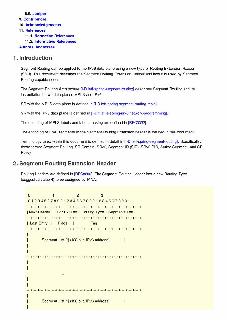
2. Segment Routing Extension HeaderRouting Headers are defined in [RFC8200]. The Segment Routing Header has a new Routing Type(suggested value 4) to be assigned by IANA.
0 1 2 3 0 1 2 3 4 5 6 7 8 9 0 1 2 3 4 5 6 7 8 9 0 1 2 3 4 5 6 7 8 9 0 1 +-+-+-+-+-+-+-+-+-+-+-+-+-+-+-+-+-+-+-+-+-+-+-+-+-+-+-+-+-+-+-+-+ | Next Header | Hdr Ext Len | Routing Type | Segments Left | +-+-+-+-+-+-+-+-+-+-+-+-+-+-+-+-+-+-+-+-+-+-+-+-+-+-+-+-+-+-+-+-+ | Last Entry | Flags | Tag | +-+-+-+-+-+-+-+-+-+-+-+-+-+-+-+-+-+-+-+-+-+-+-+-+-+-+-+-+-+-+-+-+ | | | Segment List[0] (128 bits IPv6 address) | | | | | +-+-+-+-+-+-+-+-+-+-+-+-+-+-+-+-+-+-+-+-+-+-+-+-+-+-+-+-+-+-+-+-+ | | | | ... | | | | +-+-+-+-+-+-+-+-+-+-+-+-+-+-+-+-+-+-+-+-+-+-+-+-+-+-+-+-+-+-+-+-+ | | | Segment List[n] (128 bits IPv6 address) | | |

| | +-+-+-+-+-+-+-+-+-+-+-+-+-+-+-+-+-+-+-+-+-+-+-+-+-+-+-+-+-+-+-+-+ // // // Optional Type Length Value objects (variable) // // // +-+-+-+-+-+-+-+-+-+-+-+-+-+-+-+-+-+-+-+-+-+-+-+-+-+-+-+-+-+-+-+-+
where:
0 1 2 3 4 5 6 7 +-+-+-+-+-+-+-+-+ | U |H| U | +-+-+-+-+-+-+-+-+
The Segment Routing Header (SRH) is defined as follows:
Next Header: Defined in [RFC8200]Hdr Ext Len: Defined in [RFC8200]Routing Type: TBD, to be assigned by IANA (suggested value: 4).Segments Left: Defined in [RFC8200]Last Entry: contains the index (zero based), in the Segment List, of the last element of the SegmentList.Flags: 8 bits of flags. Following flags are defined:
U: Unused and for future use. SHOULD be 0 on transmission and MUST be ignoredon receipt.
H-flag: HMAC flag. If set, the HMAC TLV is present and is encoded as the last TLV ofthe SRH. In other words, the last 36 octets of the SRH represent the HMACinformation. See Section 2.1.2 for details on the HMAC TLV.
Tag: tag a packet as part of a class or group of packets, e.g., packets sharing the same set ofproperties. When tag is not used at source it SHOULD be set to zero on transmission. When tag isnot used during SRH Processing it MUST be ignored. The allocation and use of tag is outside thescope of this document.Segment List[n]: 128 bit IPv6 addresses representing the nth segment in the Segment List. TheSegment List is encoded starting from the last segment of the SR Policy. I.e., the first element of thesegment list (Segment List [0]) contains the last segment of the SR Policy, the second elementcontains the penultimate segment of the SR Policy and so on.Type Length Value (TLV) are described in Section 2.1.
2.1. SRH TLVsThis section defines TLVs of the Segment Routing Header.
0 1 0 1 2 3 4 5 6 7 8 9 0 1 2 3 4 5 +-+-+-+-+-+-+-+-+-+-+-+-+-+-+-+-+-----------------------| Type | Length | Variable length data +-+-+-+-+-+-+-+-+-+-+-+-+-+-+-+-+-----------------------
Type: An 8 bit value. Unrecognized Types MUST be ignored on receipt.
Length: The length of the Variable length data. It is RECOMMENDED that the total length of new TLVs be

multiple of 8 bytes to avoid the use of Padding TLVs.
Variable length data: Length bytes of data that is specific to the Type.
Type Length Value (TLV) contain optional information that may be used by the node identified in theDestination Address (DA) of the packet. The information carried in the TLVs is not intended to be used bythe routing layer. Typically, TLVs carry information that is consumed by other components (e.g.: OAM) thanthe routing function.
Each TLV has its own length, format and semantic. The code-point allocated (by IANA) to each TLV Typedefines both the format and the semantic of the information carried in the TLV. Multiple TLVs may beencoded in the same SRH.
TLVs may change en route at each segment. To identify when a TLV type may change en route the mostsignificant bit of the Type has the following significance: [RFC4302].
0: TLV data does not change en route
1: TLV data does change en route
Identifying which TLVs change en route, without having to understand the Type, is required for AuthenticationHeader Integrity Check Value (ICV) computation. Any TLV that changes en route is considered mutable forthe purpose of ICV computation, the Type Length and Variable Length Data is ignored for the purpose of ICVComputation as defined in
The "Length" field of the TLV is used to skip the TLV while inspecting the SRH in case the node doesn'tsupport or recognize the Type. The "Length" defines the TLV length in octets, not including the "Type" and"Length" fields.
The following TLVs are defined in this document:
Padding TLV
HMAC TLV
Additional TLVs may be defined in the future.
2.1.1. Padding TLVsThere are two types of padding TLVs, pad0 and padN, the following applies to both:
Padding TLVs are optional and more than one Padding TLV MUST NOT appear in the SRH.
The Padding TLVs are used to align the SRH total length on the 8 octet boundary.
When present, a single Pad0 or PadN TLV MUST appear as the last TLV before the HMAC TLV (ifHMAC TLV is present).
When present, a PadN TLV MUST have a length from 0 to 5 in order to align the SRH total length on a8-octet boundary.
Padding TLVs are ignored by a node processing the SRH TLV, even if more than one is present.
Padding TLVs are ignored during ICV calculation.
2.1.1.1. PAD0
0 1 2 3 4 5 6 7 +-+-+-+-+-+-+-+-+ | Type | +-+-+-+-+-+-+-+-+

Type: to be assigned by IANA (Suggested value 128)
A single Pad0 TLV MUST be used when a single byte of padding is required. If more than one byte ofpadding is required a Pad0 TLV MUST NOT be used, the PadN TLV MUST be used.
2.1.1.2. PADN
0 1 2 3 0 1 2 3 4 5 6 7 8 9 0 1 2 3 4 5 6 7 8 9 0 1 2 3 4 5 6 7 8 9 0 1 +-+-+-+-+-+-+-+-+-+-+-+-+-+-+-+-+-+-+-+-+-+-+-+-+-+-+-+-+-+-+-+-+ | Type | Length | Padding (variable) |+-+-+-+-+-+-+-+-+-+-+-+-+-+-+-+-+-+-+-+-+-+-+-+-+-+-+-+-+-+-+-+-+// Padding (variable) //+-+-+-+-+-+-+-+-+-+-+-+-+-+-+-+-+-+-+-+-+-+-+-+-+-+-+-+-+-+-+-+-+
Type: to be assigned by IANA (suggested value 129).
Length: 0 to 5
Padding: Length octets of padding. Padding bits have no semantics. They SHOULD be set to 0 ontransmission and MUST be ignored on receipt.
The PadN TLV MUST be used when more than one byte of padding is required.
2.1.2. HMAC TLV
0 1 2 3 0 1 2 3 4 5 6 7 8 9 0 1 2 3 4 5 6 7 8 9 0 1 2 3 4 5 6 7 8 9 0 1 +-+-+-+-+-+-+-+-+-+-+-+-+-+-+-+-+-+-+-+-+-+-+-+-+-+-+-+-+-+-+-+-+ | Type | Length | RESERVED |+-+-+-+-+-+-+-+-+-+-+-+-+-+-+-+-+-+-+-+-+-+-+-+-+-+-+-+-+-+-+-+-+| HMAC Key ID (4 octets) |+-+-+-+-+-+-+-+-+-+-+-+-+-+-+-+-+-+-+-+-+-+-+-+-+-+-+-+-+-+-+-+-+| //| HMAC (32 octets) //| //+-+-+-+-+-+-+-+-+-+-+-+-+-+-+-+-+-+-+-+-+-+-+-+-+-+-+-+-+-+-+-+-+
where:
HMAC TLV is optional and contains the HMAC information. The HMAC TLV has the following format:
Type: to be assigned by IANA (suggested value 5).Length: 38.RESERVED: 2 octets. SHOULD be unset on transmission and MUST be ignored on receipt.HMAC Key ID: 4 octets.HMAC: 32 octets.HMAC and HMAC Key ID usage is described in Section 6
The Following applies to the HMAC TLV:
When present, the HMAC TLV MUST be encoded as the last TLV of the SRH.If the HMAC TLV is present, the SRH H-Flag (Figure 2) MUST be set. Nodes processing SRHSHOULD process the HMAC TLV only when the H-Flag is set, and local policy.When the H-flag is set in the SRH, the router inspecting the SRH MUST find the HMAC TLV in thelast 38 octets of the SRH.

3. SR NodesThere are different types of nodes that may be involved in segment routing networks: source SR nodesoriginate packets with a segment in the destination address of the IPv6 header, transit nodes that forwardpackets destined to a remote segment, and segment endpoint nodes that process a local segment in thedestination address of an IPv6 header.
3.1. Source SR NodeA Source SR Node is any node that originates an IPv6 packet with a segment (i.e. SRv6 SID) in thedestination address of the IPv6 header. The packet leaving the source SR Node may or may not contain anSRH. This includes either:
A host originating an IPv6 packet.
An SR domain ingress router encapsulating a received packet in an outer IPv6 header, followed by anoptional SRH.
The mechanism through which a segment in the destination address of the IPv6 header and the SegmentList in the SRH, is derived is outside the scope of this document. For example, the Segment List may beobtained through local SR Policy computation, local configuration, interaction with a controller instantiating anSR Policy, or any other mechanism.
3.2. Transit NodeA transit node is any node forwarding an IPv6 packet where the destination address of that packet is notlocally configured as a segment nor a local interface. A transit node is not required to be capable ofprocessing a segment nor SRH.
3.3. SR Segment Endpoint NodeA SR segment endpoint node is any node receiving an IPv6 packet where the destination address of thatpacket is locally configured as a segment or local interface.
4. Packet ProcessingThis section describes SRv6 packet processing at the Source, Transit and Segment Endpoint nodes.
4.1. Source SR NodeA Source node steers a packet into an SR Policy and the SRH is created as follows:
Next Header and Hdr Ext Len fields are set as specified in [RFC8200].
Routing Type field is set as TBD (to be allocated by IANA, suggested value 4).
The DA of the packet is set with the value of the first segment.
The first element of the SRH Segment List is the ultimate segment. The second element is thepenultimate segment and so on.
The Segments Left field is set to n-1 where n is the number of elements in the SR Policy.
The Last Entry field is set to n-1 where n is the number of elements in the SR Policy.
HMAC TLV may be set according to Section 6.
If the segment list contains a single segment and there is no need for information in flag or TLV, thenthe SRH MAY be omitted.
The packet is forwarded toward the packet's Destination Address (the first segment).

4.1.1. Reduced SRHWhen a source does not require the entire SID list to be preserved in the SRH, a reduced SRH may be used.
A reduced SRH does not contain the first segment of the related SR Policy (the first segment is the onealready in the DA of the IPv6 header), and the Last Entry field is set to n-2 where n is the number ofelements in the SR Policy.
4.2. Transit NodeAs specified in [RFC8200], the only node allowed to inspect the Routing Extension Header (and therefore theSRH), is the node corresponding to the DA of the packet. Any other transit node MUST NOT inspect theunderneath routing header and MUST forward the packet toward the DA according to its IPv6 routing table.
When a SID is in the destination address of an IPv6 header of a packet, it's routed through an IPv6 networkas an IPv6 address. SIDs, or the prefix(es) covering SIDs, and their reachability may be distributed bymeans outside the scope of this document. For example, [RFC5308] or [RFC5340] may be used to advertisea prefix covering the SIDs on a node.
4.3. Segment Endpoint NodeWithout constraining the details of an implementation, the Segment Endpoint Node creates ForwardingInformation Base (FIB) entries for its local SIDs.
A FIB entry that represents a locally instantiated SRv6 SID A FIB entry that represents a local interface, not locally instantiated as an SRv6 SID A FIB entry that represents a non-local route No Match
When an SRv6-capable node receives an IPv6 packet, it performs a longest-prefix-match lookup on thepackets destination address. This lookup can return any of the following:
4.3.1. FIB Entry Is Locally Instantiated SRv6 END SIDThis document, and section, defines a single SRv6 SID called END. Future documents may define additionalSRv6 SIDs. In which case, the entire content of this section will be defined in that document.
When an SRH is processed { If Segments Left is equal to zero { Skip SRH Processing } Else { If Segments Left is greater than (Last Entry+1) { Send an ICMP Parameter Problem, Code 0, message to the Source Address, pointing to the Segments Left field, and discard the packet. } Else { Decrement Segments Left by 1. Copy Segment List[Segments Left] from the SRH to the destination address of the IPv6 header. If the IPv6 Hop Limit is less than or equal to 1 { Send an ICMP Time Exceeded -- Hop Limit Exceeded in Transit message to the Source Address and discard
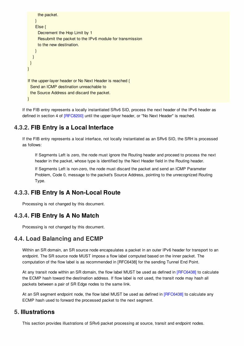
the packet. } Else { Decrement the Hop Limit by 1 Resubmit the packet to the IPv6 module for transmission to the new destination. } } }}
If the upper-layer header or No Next Header is reached { Send an ICMP destination unreachable to the Source Address and discard the packet.}
If the FIB entry represents a locally instantiated SRv6 SID, process the next header of the IPv6 header asdefined in section 4 of [RFC8200] until the upper-layer header, or "No Next Header" is reached.
4.3.2. FIB Entry is a Local InterfaceIf the FIB entry represents a local interface, not locally instantiated as an SRv6 SID, the SRH is processedas follows:
If Segments Left is zero, the node must ignore the Routing header and proceed to process the nextheader in the packet, whose type is identified by the Next Header field in the Routing header.
If Segments Left is non-zero, the node must discard the packet and send an ICMP ParameterProblem, Code 0, message to the packet's Source Address, pointing to the unrecognized RoutingType.
4.3.3. FIB Entry Is A Non-Local RouteProcessing is not changed by this document.
4.3.4. FIB Entry Is A No MatchProcessing is not changed by this document.
4.4. Load Balancing and ECMPWithin an SR domain, an SR source node encapsulates a packet in an outer IPv6 header for transport to anendpoint. The SR source node MUST impose a flow label computed based on the inner packet. Thecomputation of the flow label is as recommended in [RFC6438] for the sending Tunnel End Point.
At any transit node within an SR domain, the flow label MUST be used as defined in [RFC6438] to calculatethe ECMP hash toward the destination address. If flow label is not used, the transit node may hash allpackets between a pair of SR Edge nodes to the same link.
At an SR segment endpoint node, the flow label MUST be used as defined in [RFC6438] to calculate anyECMP hash used to forward the processed packet to the next segment.
5. IllustrationsThis section provides illustrations of SRv6 packet processing at source, transit and endpoint nodes.

5.1. Abstract Representation of an SRHFor a node k, its IPv6 address is represented as Ak, its SRv6 SID is represented as Sk.
IPv6 headers are represented as the tuple of (source, destination). For example, a packet with sourceaddress A1 and destination address A2 is represented as (A1,A2). The payload of the packet is omitted.
An SR Policy is a list of segments. A list of segments is represented as <S1,S2,S3> where S1 is the firstSID to visit, S2 is the second SID to visit and S3 is the last SID to visit.
(SA,DA) (S3, S2, S1; SL) represents an IPv6 packet with:
Source Address is SA, Destination Addresses is DA, and next-header is SRH.SRH with SID list <S1, S2, S3> with SegmentsLeft = SL.Note the difference between the <> and () symbols. <S1, S2, S3> represents a SID list where theleftmost segment is the first segment. Whereas, (S3, S2, S1; SL) represents the same SID list butencoded in the SRH Segment List format where the leftmost segment is the last segment. Whenreferring to an SR policy in a high-level use-case, it is simpler to use the <S1, S2, S3> notation.When referring to an illustration of detailed behavior, the (S3, S2, S1; SL) notation is more convenient.
Segments Left=2 Last Entry=2 Flags=0 Tag=0 Segment List[0]=S3 Segment List[1]=S2 Segment List[2]=S1
At its SR Policy headend, the Segment List <S1,S2,S3> results in SRH (S3,S2,S1; SL=2) represented fullyas:
5.2. Example Topology
+ * * * * * * * * * * * * * * * * * * * * +
* [8] [9] * | | * | | *[1]----[3]--------[5]----------------[6]---------[4]---[2] * | | * | | * | | * +--------[7]-------+ * *
+ * * * * * * * SR Domain * * * * * * * +
The following topology is used in examples below:
3 and 4 are SR Domain edge routers5, 6, and 7 are all SR Domain routers8 and 9 are hosts within the SR Domain1 and 2 are hosts outside the SR Domain
5.3. Source SR Node
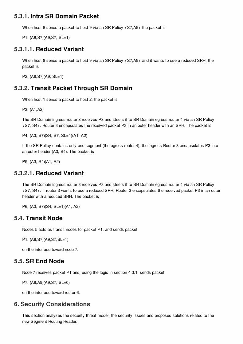
5.3.1. Intra SR Domain PacketWhen host 8 sends a packet to host 9 via an SR Policy <S7,A9> the packet is
P1: (A8,S7)(A9,S7; SL=1)
5.3.1.1. Reduced VariantWhen host 8 sends a packet to host 9 via an SR Policy <S7,A9> and it wants to use a reduced SRH, thepacket is
P2: (A8,S7)(A9; SL=1)
5.3.2. Transit Packet Through SR DomainWhen host 1 sends a packet to host 2, the packet is
P3: (A1,A2)
The SR Domain ingress router 3 receives P3 and steers it to SR Domain egress router 4 via an SR Policy<S7, S4>. Router 3 encapsulates the received packet P3 in an outer header with an SRH. The packet is
P4: (A3, S7)(S4, S7; SL=1)(A1, A2)
If the SR Policy contains only one segment (the egress router 4), the ingress Router 3 encapsulates P3 intoan outer header (A3, S4). The packet is
P5: (A3, S4)(A1, A2)
5.3.2.1. Reduced VariantThe SR Domain ingress router 3 receives P3 and steers it to SR Domain egress router 4 via an SR Policy<S7, S4>. If router 3 wants to use a reduced SRH, Router 3 encapsulates the received packet P3 in an outerheader with a reduced SRH. The packet is
P6: (A3, S7)(S4; SL=1)(A1, A2)
5.4. Transit NodeNodes 5 acts as transit nodes for packet P1, and sends packet
P1: (A8,S7)(A9,S7;SL=1)
on the interface toward node 7.
5.5. SR End NodeNode 7 receives packet P1 and, using the logic in section 4.3.1, sends packet
P7: (A8,A9)(A9,S7; SL=0)
on the interface toward router 6.
6. Security ConsiderationsThis section analyzes the security threat model, the security issues and proposed solutions related to thenew Segment Routing Header.

The Segment Routing Header (SRH) is simply another type of the routing header as described in [RFC8200]and is:
Added by an SR edge router when entering the segment routing domain or by the originating hostitself. The source host can even be outside the SR domain;inspected and acted upon when reaching the destination address of the IP header per [RFC8200].
Per [RFC8200], routers on the path that simply forward an IPv6 packet (i.e. the IPv6 destination address isnone of theirs) will never inspect and process the content of the SRH. Routers whose FIB contains a locallyinstantiated SRv6 SID equal to the destination address field of the IPv6 packet MUST parse the SRH and, ifsupported and if the local configuration allows it, MUST act accordingly to the SRH content.
As specified in [RFC8200], the default behavior of a non SR-capable router upon receipt of an IPv6 packetwith SRH destined to an address of its, is to:
ignore the SRH completely if the Segment Left field is 0 and proceed to process the next header inthe IPv6 packet;discard the IPv6 packet if Segment Left field is greater than 0, it MAY send a Parameter ProblemICMP message back to the Source Address.
6.1. Threat model
6.1.1. Source routing threatsUsing an SRH is similar to source routing, therefore it has some well-known security issues as described in[RFC4942] section 2.1.1 and [RFC5095]:
amplification attacks: where a packet could be forged in such a way to cause looping among a set ofSR-enabled routers causing unnecessary traffic, hence a Denial of Service (DoS) against bandwidth;reflection attack: where a hacker could force an intermediate node to appear as the immediateattacker, hence hiding the real attacker from naïve forensic;bypass attack: where an intermediate node could be used as a stepping stone (for example in a De-Militarized Zone) to attack another host (for example in the datacenter or any back-end server).
6.1.2. Applicability of RFC 5095 to SRHFirst of all, the reader must remember this specific part of section 1 of [RFC5095], "A side effect is that thisalso eliminates benign RH0 use-cases; however, such applications may be facilitated by future RoutingHeader specifications.". In short, it is not forbidden to create new secure type of Routing Header; forexample, [RFC6554] (RPL) also creates a new Routing Header type for a specific application confined in asingle network.
In the segment routing architecture described in [I-D.ietf-spring-segment-routing] there are basically two kindsof nodes (routers and hosts):
nodes within the SR domain, which is within one single administrative domain, i.e., where all nodesare trusted anyway else the damage caused by those nodes could be worse than amplificationattacks: traffic interception, man-in-the-middle attacks, more server DoS by dropping packets, and soon.nodes outside of the SR domain, which is outside of the administrative segment routing domain hencethey cannot be trusted because there is no physical security for those nodes, i.e., they can bereplaced by hostile nodes or can be coerced in wrong behaviors.
The main use case for SR consists of the single administrative domain where only trusted nodes with SRenabled and configured participate in SR: this is the same model as in [RFC6554]. All non-trusted nodes donot participate as either SR processing is not enabled by default or because they only process SRH from

nodes within their domain.
Moreover, all SR nodes ignore SRH created by outsiders based on topology information (received on apeering or internal interface) or on presence and validity of the HMAC field. Therefore, if intermediate nodesONLY act on valid and authorized SRH (such as within a single administrative domain), then there is nosecurity threat similar to RH-0. Hence, the [RFC5095] attacks are not applicable.
6.1.3. Service stealing threatSegment routing is used for added value services, there is also a need to prevent non-participating nodes touse those services; this is called 'service stealing prevention'.
6.1.4. Topology disclosureThe SRH may also contains SIDs of some intermediate SR-nodes in the path towards the destination, thisobviously reveals those addresses to the potentially hostile attackers if those attackers are able to interceptpackets containing SRH. On the other hand, if the attacker can do a traceroute whose probes will beforwarded along the SR Policy, then there is little learned by intercepting the SRH itself.
6.1.5. ICMP GenerationPer Section 4.4 of [RFC8200], when destination nodes (i.e. where the destination address is one of theirs)receive a Routing Header with unsupported Routing Type, the required behavior is:
If Segments Left is zero, the node must ignore the Routing header and proceed to process the nextheader in the packet.If Segments Left is non-zero, the node must discard the packet and send an ICMP ParameterProblem, Code 0, message to the packet's Source Address, pointing to the unrecognized RoutingType.
This required behavior could be used by an attacker to force the generation of ICMP message by any node.The attacker could send packets with SRH (with Segment Left not set to 0) destined to a node not supportingSRH. Per [RFC8200], the destination node could generate an ICMP message, causing a local CPU utilizationand if the source of the offending packet with SRH was spoofed could lead to a reflection attack without anyamplification.
It must be noted that this is a required behavior for any unsupported Routing Type and not limited to SRHpackets. So, it is not specific to SRH and the usual rate limiting for ICMP generation is required anyway forany IPv6 implementation and has been implemented and deployed for many years.
6.2. Security fields in SRHThis section summarizes the use of specific fields in the SRH. They are based on a key-hashed messageauthentication code (HMAC).
The security-related fields in the SRH are instantiated by the HMAC TLV, containing:
HMAC Key-id, 32 bits wide;HMAC, 256 bits wide (optional, exists only if HMAC Key-id is not 0).
The HMAC field is the output of the HMAC computation (per [RFC2104]) using a pre-shared key identified byHMAC Key-id and of the text which consists of the concatenation of:
the source IPv6 address;Last Entry field;an octet of bit flags;

HMAC Key-id;all addresses in the Segment List.
The purpose of the HMAC TLV is to verify the validity, the integrity and the authorization of the SRH itself. Ifan outsider of the SR domain does not have access to a current pre-shared secret, then it cannot computethe right HMAC field and the first SR router on the path processing the SRH and configured to check thevalidity of the HMAC will simply reject the packet.
The HMAC TLV is located at the end of the SRH simply because only the router on the ingress of the SRdomain needs to process it, then all other SR nodes can ignore it (based on local policy) because they trustthe upstream router. This is to speed up forwarding operations because SR routers which do not validate theSRH do not need to parse the SRH until the end.
The HMAC Key-id field allows for the simultaneous existence of several hash algorithms (SHA-256, SHA3-256 ... or future ones) as well as pre-shared keys. The HMAC Key-id field is opaque, i.e., it has neithersyntax nor semantic except as an index to the right combination of pre-shared key and hash algorithm andexcept that a value of 0 means that there is no HMAC field. Having an HMAC Key-id field allows for pre-shared key roll-over when two pre-shared keys are supported for a while when all SR nodes converged to afresher pre-shared key. It could also allow for interoperation among different SR domains if allowed by localpolicy and assuming a collision-free HMAC Key Id allocation.
When a specific SRH is linked to a time-related service (such as turbo-QoS for a 1-hour period) where theDA, Segment ID (SID) are identical, then it is important to refresh the shared-secret frequently as the HMACvalidity period expires only when the HMAC Key-id and its associated shared-secret expires.
6.2.1. Selecting a hash algorithmThe HMAC field in the HMAC TLV is 256 bit wide. Therefore, the HMAC MUST be based on a hash functionwhose output is at least 256 bits. If the output of the hash function is 256, then this output is simply insertedin the HMAC field. If the output of the hash function is larger than 256 bits, then the output value is truncatedto 256 by taking the least-significant 256 bits and inserting them in the HMAC field.
SRH implementations can support multiple hash functions but MUST implement SHA-2 in its SHA-256variant.
NOTE: SHA-1 is currently used by some early implementations used for quick interoperations testing, the160-bit hash value must then be right-hand padded with 96 bits set to 0. The authors understand that this isnot secure but is ok for limited tests.
6.2.2. Performance impact of HMACWhile adding an HMAC to each and every SR packet increases the security, it has a performance impact.Nevertheless, it must be noted that:
the HMAC field is used only when SRH is added by a device (such as a home set-up box) which isoutside of the segment routing domain. If the SRH is added by a router in the trusted segment routingdomain, then, there is no need for an HMAC field, hence no performance impact.when present, the HMAC field MUST only be checked and validated by the first router of the segmentrouting domain, this router is named 'validating SR router'. Downstream routers may not inspect theHMAC field.this validating router can also have a cache of <IPv6 header + SRH, HMAC field value> to improvethe performance. It is not the same use case as in IPsec where HMAC value was unique per packet,in SRH, the HMAC value is unique per flow.Last point, hash functions such as SHA-2 have been optimized for security and performance andthere are multiple implementations with good performance.
With the above points in mind, the performance impact of using HMAC is minimized.
6.2.3. Pre-shared key managementThe field HMAC Key-id allows for:
key roll-over: when there is a need to change the key (the hash pre-shared secret), then multiple pre-shared keys can be used simultaneously. The validating routing can have a table of <HMAC Key-id,pre-shared secret> for the currently active and future keys.different algorithms: by extending the previous table to <HMAC Key-id, hash function, pre-sharedsecret>, the validating router can also support simultaneously several hash algorithms (see sectionSection 6.2.1)
The pre-shared secret distribution can be done:
in the configuration of the validating routers, either by static configuration or any SDN orientedapproach;dynamically using a trusted key distribution such as [RFC6407]
The intent of this document is NOT to define yet-another-key-distribution-protocol.
6.3. Deployment Models
6.3.1. Nodes within the SR domainAn SR domain is defined as a set of interconnected routers where all routers at the perimeter are configuredto add and act on SRH. Some routers inside the SR domain can also act on SRH or simply forward IPv6packets.
The routers inside an SR domain can be trusted to generate SRH and to process SRH received on interfacesthat are part of the SR domain. These nodes MUST drop all SRH packets received on an interface that is notpart of the SR domain, destined to a locally instantiated SID, and containing an SRH whose HMAC fieldcannot be validated by local policies. This includes obviously packet with an SRH generated by a non-cooperative SR domain.
If the validation fails, then these packets MUST be dropped, ICMP error messages (parameter problem)SHOULD be generated (but rate limited) and SHOULD be logged.
6.3.2. Nodes outside of the SR domainNodes outside of the SR domain cannot be trusted for physical security; hence, they need to request bysome trusted means (outside the scope of this document) a complete SRH for each new connection (i.e. newdestination address). The received SRH MUST include an HMAC TLV which is computed correctly (seeSection 6.2).
When an outside node sends a packet with an SRH and towards an SR domain ingress node, the packetMUST contain the HMAC TLV (with a Key-id and HMAC fields) and the the destination address MUST be anaddress of an SR domain ingress node .
The ingress SR router, i.e., the router with a SID equal to the destination address, MUST verify the HMACTLV.
If the validation is successful, then the packet is simply forwarded as usual for an SR packet. As long as thepacket travels within the SR domain, no further HMAC check needs to be done. Subsequent routers in theSR domain MAY verify the HMAC TLV when they process the SRH (i.e. when they are the destination).
If the validation fails, then this packet MUST be dropped, an ICMP error message (parameter problem)

SHOULD be generated (but rate limited) and SHOULD be logged.
6.3.3. SR path exposureAs the intermediate SR nodes addresses appears in the SRH, if this SRH is visible to an outsider thenhe/she could reuse this knowledge to launch an attack on the intermediate SR nodes or get some insiderknowledge on the topology. This is especially applicable when the path between the source node and the firstSR domain ingress router is on the public Internet.
The first remark is to state that 'security by obscurity' is never enough; in other words, the security policy ofthe SR domain MUST assume that the internal topology and addressing is known by the attacker. A simpletraceroute will also give the same information (with even more information as all intermediate nodes betweenSID will also be exposed). IPsec Encapsulating Security Payload [RFC4303] cannot be use to protect theSRH as per RFC4303 the ESP header must appear after any routing header (including SRH).
To prevent a user to leverage the gained knowledge by intercepting SRH, it it recommended to apply aninfrastructure Access Control List (iACL) at the edge of the SR domain. This iACL will drop all packets fromoutside the SR-domain whose destination is any address of any router interface or SID inside the domain.This security policy should be tuned for local operations.
6.3.4. Impact of BCP-38BCP-38, also known as "Network Ingress Filtering", checks whether the source address of packets receivedon an interface is valid for this interface. The use of loose source routing such as SRH forces packets tofollow a path which differs from the expected routing. Therefore, if BCP-38 was implemented in all routersinside the SR domain, then SR packets could be received by an interface which is not expected one and thepackets could be dropped.
As an SR domain is usually a subset of one administrative domain, and as BCP-38 is only deployed at theingress routers of this administrative domain and as packets arriving at those ingress routers have beennormally forwarded using the normal routing information, then there is no reason why this ingress routershould drop the SRH packet based on BCP-38. Routers inside the domain commonly do not apply BCP-38;so, this is not a problem.
7. IANA Considerations
Suggested Description Reference Value---------------------------------------------------------- 4 Segment Routing Header (SRH) This document
This document makes the following registrations in the Internet Protocol Version 6 (IPv6) Parameters"Routing Type" registry maintained by IANA:
This document request IANA to create and maintain a new Registry: "Segment Routing Header TLVs"
7.1. Segment Routing Header Flags Register
Suggested Description Reference Bit----------------------------------------------------- 4 HMAC This document
This document requests the creation of a new IANA managed registry to identify SRH Flags Bits. Theregistration procedure is "Expert Review" as defined in [RFC8126]. Suggested registry name is "Segment

Routing Header Flags". Flags is 8 bits, the following bits are defined in this document:
7.2. Segment Routing Header TLVs Register
Suggested Description Reference Value----------------------------------------------------- 5 HMAC TLV This document 128 Pad0 TLV This document 129 PadN TLV This document
This document requests the creation of a new IANA managed registry to identify SRH TLVs. The registrationprocedure is "Expert Review" as defined in [RFC8126]. Suggested registry name is "Segment RoutingHeader TLVs". A TLV is identified through an unsigned 8 bit codepoint value. The following codepoints aredefined in this document:
8. Implementation StatusThis section is to be removed prior to publishing as an RFC.
8.1. LinuxName: Linux Kernel v4.14
Status: Production
Implementation: adds SRH, performs END processing, supports HMAC TLV
Details: https://irtf.org/anrw/2017/anrw17-final3.pdf and [I-D.filsfils-spring-srv6-interop]
8.2. Cisco SystemsName: IOS XR and IOS XE
Status: Pre-production
Implementation: adds SRH, performs END processing, no TLV processing
Details: [I-D.filsfils-spring-srv6-interop]
8.3. FD.ioName: VPP/Segment Routing for IPv6
Status: Production
Implementation: adds SRH, performs END processing, no TLV processing
Details: https://wiki.fd.io/view/VPP/Segment_Routing_for_IPv6 and [I-D.filsfils-spring-srv6-interop]
8.4. BarefootName: Barefoot Networks Tofino NPU
Status: Prototype
Implementation: performs END processing, no TLV processing

Details: [I-D.filsfils-spring-srv6-interop]
8.5. JuniperName: Juniper Networks Trio and vTrio NPU's
Status: Prototype & Experimental
Implementation: SRH insertion mode, Process SID where SID is an interface address, no TLV processing
9. ContributorsKamran Raza, Darren Dukes, Brian Field, Daniel Bernier, Ida Leung, Jen Linkova, Ebben Aries, TomoyaKosugi, Eric Vyncke, David Lebrun, Dirk Steinberg, Robert Raszuk, Dave Barach, John Brzozowski, PierreFrancois, Nagendra Kumar, Mark Townsley, Christian Martin, Roberta Maglione, James Connolly, AloysAugustin contributed to the content of this document.
10. AcknowledgementsThe authors would like to thank Ole Troan, Bob Hinden, Ron Bonica, Fred Baker, Brian Carpenter, AlexandruPetrescu, Punit Kumar Jaiswal, and David Lebrun for their comments to this document.
11. References
11.1. Normative References
[FIPS180-4] National Institute of Standards and Technology, "FIPS 180-4 Secure HashStandard (SHS)", March 2012.
[I-D.ietf-spring-segment-routing] Filsfils, C., Previdi, S., Ginsberg, L., Decraene, B., Litkowski, S. and R.Shakir, "Segment Routing Architecture", Internet-Draft draft-ietf-spring-segment-routing-15, January 2018.
[RFC2119] Bradner, S., "Key words for use in RFCs to Indicate Requirement Levels",BCP 14, RFC 2119, DOI 10.17487/RFC2119, March 1997.
[RFC4303] Kent, S., "IP Encapsulating Security Payload (ESP)", RFC 4303, DOI10.17487/RFC4303, December 2005.
[RFC5095] Abley, J., Savola, P. and G. Neville-Neil, "Deprecation of Type 0 RoutingHeaders in IPv6", RFC 5095, DOI 10.17487/RFC5095, December 2007.
[RFC6407] Weis, B., Rowles, S. and T. Hardjono, "The Group Domain ofInterpretation", RFC 6407, DOI 10.17487/RFC6407, October 2011.
[RFC8200] Deering, S. and R. Hinden, "Internet Protocol, Version 6 (IPv6)Specification", STD 86, RFC 8200, DOI 10.17487/RFC8200, July 2017.
11.2. Informative References
[I-D.filsfils-spring-srv6-interop] Filsfils, C., Clad, F., Camarillo, P., Abdelsalam, A., Salsano,S., Bonaventure, O., Horn, J. and J. Liste, "SRv6interoperability report", Internet-Draft draft-filsfils-spring-srv6-interop-00, March 2018.

[I-D.filsfils-spring-srv6-network-programming] Filsfils, C., Li, Z., Leddy, J., [email protected], d.,[email protected], d., Steinberg, D., Raszuk, R.,Matsushima, S., Lebrun, D., Decraene, B., Peirens, B.,Salsano, S., Naik, G., Elmalky, H., Jonnalagadda, P. and M.Sharif, "SRv6 Network Programming", Internet-Draft draft-filsfils-spring-srv6-network-programming-04, March 2018.
[I-D.ietf-spring-segment-routing-mpls] Bashandy, A., Filsfils, C., Previdi, S., Decraene, B.,Litkowski, S. and R. Shakir, "Segment Routing with MPLSdata plane", Internet-Draft draft-ietf-spring-segment-routing-mpls-13, April 2018.
[RFC2104] Krawczyk, H., Bellare, M. and R. Canetti, "HMAC: Keyed-Hashing for Message Authentication", RFC 2104, DOI10.17487/RFC2104, February 1997.
[RFC2827] Ferguson, P. and D. Senie, "Network Ingress Filtering:Defeating Denial of Service Attacks which employ IP SourceAddress Spoofing", BCP 38, RFC 2827, DOI10.17487/RFC2827, May 2000.
[RFC3032] Rosen, E., Tappan, D., Fedorkow, G., Rekhter, Y.,Farinacci, D., Li, T. and A. Conta, "MPLS Label StackEncoding", RFC 3032, DOI 10.17487/RFC3032, January2001.
[RFC4302] Kent, S., "IP Authentication Header", RFC 4302, DOI10.17487/RFC4302, December 2005.
[RFC4942] Davies, E., Krishnan, S. and P. Savola, "IPv6 Transition/Co-existence Security Considerations", RFC 4942, DOI10.17487/RFC4942, September 2007.
[RFC5308] Hopps, C., "Routing IPv6 with IS-IS", RFC 5308, DOI10.17487/RFC5308, October 2008.
[RFC5340] Coltun, R., Ferguson, D., Moy, J. and A. Lindem, "OSPF forIPv6", RFC 5340, DOI 10.17487/RFC5340, July 2008.
[RFC6438] Carpenter, B. and S. Amante, "Using the IPv6 Flow Label forEqual Cost Multipath Routing and Link Aggregation inTunnels", RFC 6438, DOI 10.17487/RFC6438, November2011.
[RFC6554] Hui, J., Vasseur, JP., Culler, D. and V. Manral, "An IPv6Routing Header for Source Routes with the Routing Protocolfor Low-Power and Lossy Networks (RPL)", RFC 6554, DOI10.17487/RFC6554, March 2012.
[RFC8126] Cotton, M., Leiba, B. and T. Narten, "Guidelines for Writingan IANA Considerations Section in RFCs", BCP 26, RFC8126, DOI 10.17487/RFC8126, June 2017.
Authors' AddressesStefano PrevidiIndividualItalyEMail: [email protected]
Clarence Filsfils (editor)Cisco Systems, Inc.

Brussels,BEEMail: [email protected]
John LeddyComcast4100 East Dry Creek RoadCentennial, CO 80122USEMail: [email protected]
Satoru MatsushimaSoftbankEMail: [email protected]
Daniel Voyer (editor)Bell CanadaEMail: [email protected]