ir a-25-2.10: metal suspension systems for lay-in panel ceilings
TRANSCRIPT

DSA IR 25-2.10 Metal Suspension Systems (rev 05-16-13) For Lay-In Panel Ceilings: 2010 CBC Page 1 of 14
California Department of General Services . Division of the State Architect . Interpretation of Regulations Document
METAL SUSPENSION SYSTEMS FOR LAY-IN PANEL CEILINGS: 2010 CBC IR 25-2.10
References: California Code of Regulations (CCR), Title 24, Part 2: 2010 California Building Code (CBC), Section 1615A.1.16, 1615.10.13* ASTM C635-07, C636-06, and E580-08
Discipline: Structural
Revised 05-16-13 Revised 12-21-12
Revised in its entirety 05-18-11
Issued 06-22-09 as IR 25-5
This Interpretation of Regulations (IR) is intended for use by the Division of the State Architect (DSA) staff, and as a resource for design professionals, to promote more uniform statewide criteria for plan review and construction inspection of projects within the jurisdiction of DSA which includes State of California public elementary and secondary schools (grades K-12), community colleges and state-owned or state-leased essential services buildings. This IR indicates an acceptable method for achieving compliance with applicable codes and regulations, although other methods proposed by design professionals may be considered by DSA. This IR is reviewed on a regular basis and is subject to revision at any time. Please check the DSA web site for currently effective IRs. Only IRs listed in the document at http://www.dgs.ca.gov/dsa/Resources/IRManual.aspx at the time of plan submittal to DSA are considered applicable.
* Indicates alternative 2010 CBC sections that may be used by community colleges, per 2010 CBC Section 1.9.2.2.
PURPOSE: The purpose of this Interpretation of Regulations (IR) is to provide guidelines
for the installation of metal suspension systems for lay-in ceilings on projects approved under the 2010 California Building Code (CBC). For projects submitted to the DSA for review
under the 2001 or 2007 CBC, see IR 25-2.01 or IR 25-2.07 respectively.
1. GENERAL REQUIREMENTS: CBC Section 1615A1.16 (1615.10.13*) requires the
design and installation to be in compliance with ASTM C635, C636, and E580, Section 5, as
amended by 2010 CBC Section 1615A.1.16 (1615.10.13*).
Note: Amendments in CBC Section 1615A.1.16 (1615.10.13*) replace ASCE 7,
Section 13.5.6.
The requirements in this IR apply to flat and level ceiling systems whose total weight,
including ceiling mounted air terminals, services and light fixtures, does not exceed four (4)
psf. Heavy systems, systems that are not flat and level, and those supporting lateral loads from partitions are beyond the scope of this IR and will require special design details.
2. SUSPENSION SYSTEM COMPONENTS: Shall comply with ASTM C635 and
Section 5.1 of ASTM E580.
2.1 The ceiling grid system must be rated heavy duty as defined by ASTM C635.
2.2 Suspension wires shall be #12 gage (0.106” diameter), soft annealed, and galvanized steel wires with Class 1 coating.
2.3 Main runners, cross runners, splices, expansion devices, and intersection connectors shall be designed to carry a mean ultimate test load of not less than 180 lbs. in
compression and tension per ASTM E580 Section 5.1.2.
3. SUSPENSION SYSTEM INSTALLATION: Shall comply with ASTM C636 and
Section 5.2 of ASTM E580.
3.1 #12 gage hanger wires may be used for up to and including 4 ft. by 4 ft. grid spacing and shall be attached to main runners.
3.2 Provide #12 gage hanger wires at the ends of all main and cross runners within eight (8) inches of the support or within one-fourth (1/4) of the length of the end tee,
whichever is least, for the perimeter of the ceiling area (see Figure 2). Perimeter wires are not required when the length of the end tee is eight (8) inches or less.

DSA IR 25-2.10 Metal Suspension Systems (rev 05-16-13) For Lay-In Panel Ceilings: 2010 CBC Page 2 of 14
3.3 Ceiling grid members shall be attached to two (2) adjacent walls per ASTM E580,
Section 5.2.3. Ceiling grid members shall be at least 3/4 inch clear of other walls. If walls run diagonally to ceiling grid system runners, one end of main and cross
runners should be free, and a minimum of 3/4 inch clear of wall.
3.4 The width of the perimeter supporting closure angle shall be not less than 2 inches.
Grid systems with specialty angles and support clips may be acceptable in accordance with Section 11 below.
3.5 At the perimeter of the ceiling area, where main or cross runners are not connected to the adjacent wall, provide interconnection between the runners at the free end to
prevent lateral spreading. A metal spreader strut or a #16 gage wire with a positive
mechanical connection to the runner may be used. Where the perpendicular distance from the wall to the first parallel runner is 8 inches or less, this interlock is not
required.
4. EXPANSION JOINTS, SEISMIC SEPARATION JOINTS, AND
PENETRATIONS:
4.1 Expansion joints shall be provided in the ceiling at intersections of corridors and at junctions of corridors and lobbies or other similar areas (see Figure 7, Detail A).
4.2 For ceiling areas exceeding 2500 square feet, a seismic separation joint shall be provided in accordance with Figure 7, Detail A, to divide the ceiling into areas not
exceeding 2500 square feet. Alternatively, comply with ASTM E580, Section 5.2.9.
4.3 Penetrations through the ceiling for sprinkler heads and other similar devices that are not integrally tied to the ceiling system in the lateral direction shall have a two
(2) inch oversized ring, sleeve or adapter through the ceiling tile to allow free movement of one (1) inch in all horizontal directions. Alternatively, per ASTM E580,
Section 5.2.8.8, a flexible sprinkler hose fitting that can accommodate 1 inch of ceiling movement shall be permitted to be used in lieu of the oversized ring, sleeve,
or adapter.
5. LATERAL FORCE BRACING: Lateral force bracing is required per this section for
all ceiling areas. The spacing of the bracing assemblies must be shown on the
construction documents.
Exception: Lateral force bracing may be omitted for suspended acoustical ceiling
systems with a ceiling area of 144 square feet or less, and fire rated suspended acoustical ceiling systems with a ceiling area of 96 square feet or less, when
perimeter support, in accordance with Section 3.4 of this IR or with ASTM E580
Sections 5.2.2 and 5.2.3, are provided and perimeter walls are designed to carry the ceiling lateral forces.
5.1 Provide lateral force bracing assemblies consisting of a compression strut and four (4) #12 gage splayed bracing wires oriented 90 degrees from each other (see Figure
1).
5.2 Lateral force bracing assemblies shall be spaced at a maximum of 12 feet by 12 feet
on centers for school buildings and 8 feet by 12 feet on centers for essential services buildings. There shall be a brace assembly a distance of not more than one half of
the above spacing from each surrounding wall, expansion joint and at the edges of
any ceiling vertical offsets.
5.3 The slope of bracing wires shall not exceed 45 degrees from the plane of the ceiling and wires shall be taut. Splices in wires are not permitted without DSA approval.
DSA IR 25-2.10 Metal Suspension Systems (rev 05-16-13) For Lay-In Panel Ceilings: 2010 CBC Page 3 of 14
5.4 Compression struts shall be adequate to resist the vertical component induced by the
bracing wires, and shall not be more than 1 (horizontal) in 6 (vertical) out of plumb.
6. ATTACHMENT OF HANGER AND BRACING WIRES:
6.1 Fasten #12 hanger wires with not less than three (3) tight turns in 3 inches. Hanger wire loops shall be tightly wrapped and sharply bent to prevent any vertical
movement or rotation of the member within the loops (see ASTM E580, Section
5.2.7.2).
6.2 Fasten #10 or #12 bracing wires with four (4) tight turns. Make all tight turns within
a distance of 1-1/2 inches.
6.3 Hanger or bracing wire anchored to the structure should be installed in such a
manner that the direction of the anchor aligns as closely as possible with the direction of the wire.
6.4 Separate all ceiling hanger and bracing wires at least six (6) inches from all unbraced ducts, pipes, conduit, etc.
6.5 Hanger wires shall not attach to or bend around interfering material or equipment.
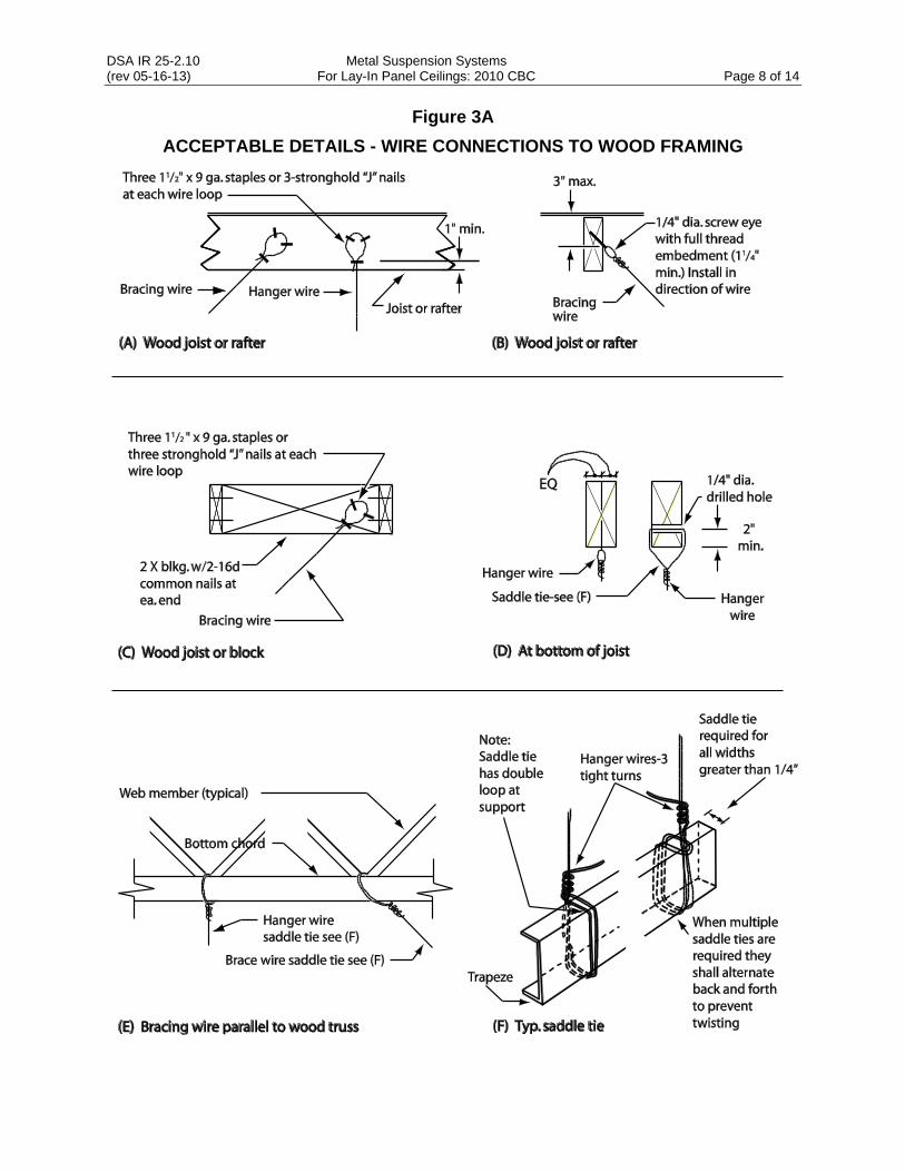
Provide trapeze or other supplementary support members at obstructions to typical hanger spacing (see Figure 3A, Detail F). Provide additional hangers, struts or braces
as required at all ceiling breaks, soffits, or discontinuous areas.
6.6 Hanger wires that are more than 1 (horizontal) in 6 (vertical) out of plumb shall have
counter-sloping wires. Perimeter hanger wires at main runners that are positively attached to the perimeter closure angle, counter-sloping is optional.
Note : See ASTM C-636, Figure 1, for counter-sloping methods.
6.7 When connection details differ from those in the attached figures, attachment of
bracing wires to the structure above and to the main runners shall be adequate for
the load imposed. The weight (Wp) shall be taken as not less than 4 psf for calculating seismic forces (Fp).
6.8 When drilled-in concrete anchors or shot-in anchors are used in reinforced concrete for hanger wires, 1 out of 10 wire/anchor assemblies must be field tested for 200
lbs. in tension. When drilled-in concrete anchors are used for bracing wires, 1 out of 2 wire/anchor assemblies must be field tested for 440 lbs. in tension in the direction
of the wire. Shot-in anchors in concrete are not permitted for bracing wires.
Note: Drilled-in or shot-in anchors require DSA approval prior to use in prestressed
concrete.
7. CEILING FIXTURES, TERMINALS, AND DEVICES: All fixtures, terminals,
and other devices shall be mounted in a manner that will not compromise ceiling
performance in accordance with Section 13.5.6.2.2(5) of ASCE 7-05 as amended by 2010 CBC Section 1615A.1.16 (1615.10.13*) and ASTM E580 Sections 5.3 and 5.4.
7.1 Ceiling panels shall not support any light fixtures, air terminals or devices.
7.2 Attach all light fixtures, ceiling mounted air terminals, and all other devices to the ceiling grid runners to resist a horizontal force equal to the weight of the fixtures.
Screws or approved fasteners are required. A minimum of two attachments are required at each light fixture, per ASTM E580, Section 5.3.1.
7.3 Recessed or drop-in light fixtures, grilles, mechanical terminals, and flexible sprinkler hose fittings or other services be supported directly on runners classified as ASTM
heavy duty, but they must also have a minimum of two (2) #12 gage slack safety wires attached to the fixture at diagonal corners and anchored to the structure
above.

DSA IR 25-2.10 Metal Suspension Systems (rev 05-16-13) For Lay-In Panel Ceilings: 2010 CBC Page 4 of 14
7.4 All flush or recessed light fixtures, mechanical terminals, and flexible sprinkler hose
fittings or other services weighing 56 lbs. or more must be independently supported by not less than four (4) taut #12 gage wires attached to the housing and to the
structure above. The four (4) taut #12 gage wires, including their attachment to the structure above, must be capable of supporting four (4) times the weight of the unit.
7.5 All 4 ft. x 4 ft. light fixtures must have slack safety wires at each corner.
7.6 Surface-mounted fixtures shall be attached to the main runner with at least two
positive clamping devices made of material with a minimum #14 gage. Rotational spring catches do not comply. A #12 gage suspension wire shall be attached to each
clamping device to the structure above. Provide additional supports when light
fixtures are 8 ft. or longer. Maximum spacing between supports shall not exceed 8 feet.
7.7 Support pendant-mounted light fixtures directly from the structure above with hanger wires or cables passing through each pendant hanger and capable of
supporting two (2) times the weight of the fixture. See IR 16-9 for additional requirements for pendent mounted fixtures
If the pendant mounted light fixture is directly and independently braced below the ceiling, i.e. aircraft cables to walls, then a brace assembly is not required above the
ceiling.
If the pendant mounted light fixture is not directly and independently braced below the ceiling, then a bracing assembly, per Figure 1, is required where the pendant
hanger penetrates the ceiling. Special details are required to attach the pendant hanger to the bracing assembly to transmit horizontal force. Exception: Where the
weight of the fixture is less than 20 pounds, the compression post shown in Figure 1 is not required.
7.8 All lightweight miscellaneous devices, such as strobe lights, speakers, etc., shall be attached to the ceiling grid per Section 7.1 of this IR. In addition, devices weighing
more than 10 lbs shall have a #12 slack safety wire anchored to the structure above.
Devices weighing more than 20 lbs shall be supported from the structure above per Section 7.3 of this IR.
8. ADDITIONAL REQUIREMENTS:
8.1 Fire Rated Ceilings:
Provide a detail and design number for rated ceiling assemblies from an authorized
testing agency. The components and installation details must conform in every respect with the listed detail and number. Details shall clearly depict all components,
including insulation materials, framing and attachment of the design so that the assembly can be constructed and inspected accordingly.
Pop rivets, screws, or other attachments are not acceptable unless specifically detailed on the drawings and approved by U.L. and State Fire Marshal (SFM)
recognized laboratories.
8.2 Metal and Other Panels:
Metal panels and panels weighing more than 1/2 psf, other than mineral fiber
acoustical tile, are to be positively attached to the ceiling suspension runners.
8.3 Essential Services Buildings:
Exitways shall be installed in accordance with Section 13.5.6.2.2(1) of ASCE 7-05 as amended by 2010 CBC Section 1615A.1.16 (1615.10.13*). A main or cross runner
shall be installed on all sides of each piece of tile, board or panel and each light fixture or grill (see Figure 7, Detail B). Splices or intersection of such runners shall

DSA IR 25-2.10 Metal Suspension Systems (rev 05-16-13) For Lay-In Panel Ceilings: 2010 CBC Page 5 of 14
be attached with through connectors such as pop rivets, screws, pins, plates with
end tabs or other approved connectors.
8.4 Suspended Acoustical Ceilings Below Gypsum Board Ceilings:
Where gypsum board or other ceiling finishes are attached to the framing, specific details will be required for the vertical hanger wire and lateral bracing wire support
connections to the framing.
9. RE-USE OF EXISTING CEILING HANGER WIRES AND BRACING WIRES:
9.1 The gage and spacing of the wires must comply with the current applicable codes.
9.2 All existing ceiling hanger wire/anchor assemblies must be tested to 200 lbs.
9.3 All existing bracing wire/anchor assemblies must be field tested to 440 lbs.
9.4 If a new wire is to be spliced to an existing wire, the following is required:
The architect or structural engineer in general responsible charge must submit
to the DSA for approval a detail and specification describing how the splice is to be made.
All new wires, after being spliced to the existing wires, must be field tested per Sections 9.2 and 9.3 above.
All field tests must be performed in the presence of the project inspector.
10. MODERNIZATION AND ALTERATION: The entire ceiling shall be upgraded to
meet the current requirements of the CBC and this IR if any portion of the grid system is cut
or altered.
Exception: The replacement of existing ceiling panels with panels of the same
materials and light fixtures of the same size, locations, and weights does not require an upgrade to the ceiling grid and suspension system.
11. DSA ACCEPTANCE REPORT: DSA no longer issues Acceptance Reports for
products. Ceiling grid systems or components, with valid evaluation reports issued by qualified evaluation agencies, in accordance with DSA IR A-5, are accepted by the DSA,
provided the system or component meets the requirements of CBC Section 1615A.1.16 (1615.10.13*), ASTM C635, C636 and E580. Where a qualified evaluation report is utilized,
the installation shall comply with all the requirements specified in the evaluation report, i.e. connections, member sizes, perimeter details, special clips to wall angles, etc.
12. CONSTRUCTION DOCUMENTS: Drawings and specifications shall clearly
identify all systems and shall define or show all supporting details, lighting fixture attachment, lateral force bracing, partition bracing, seismic separations, etc. Where
differences occur between provisions of this IR and the CBC, the provisions of the CBC shall
apply.
A list of acceptable grid systems must be shown on the drawings. The grid systems
specified shall have valid evaluation reports in accordance with IR A-5. The following information shall be included on the drawings for each acceptable grid system specified:
Classification of ceiling grid is heavy duty.
Manufacturer's catalog number - main runner (1) (2) .
Manufacturer's catalog number - cross runner (2) (3) .
Manufacturer's catalog number of detail for runner splice (2) .
Notes: (1) Main runners must be rated as heavy duty.
(2) Show manufacturer, duty classification and catalog numbers.
(3) If a cross runner supports light fixtures, air terminals, or other cross runners, it shall be
considered a main runner for the purpose of structural classification.

DSA IR 25-2.10 Metal Suspension Systems (rev 05-16-13) For Lay-In Panel Ceilings: 2010 CBC Page 6 of 14
Figure 1
SUSPENDED CEILING BRACING ASSEMBLY
Compression struts:
Compression struts shall not replace hanger wires. The sizes of compression struts must be shown on construction documents by the engineer or architect. Attach compression struts to main runners within 2" of cross runner. Details of attachment at both ends must be designed and shown on construction documents by the engineer or architect. The attachment at the top shall be capable of supporting four times the weight of the strut.

DSA IR 25-2.10 Metal Suspension Systems (rev 05-16-13) For Lay-In Panel Ceilings: 2010 CBC Page 7 of 14
Figure 2
CEILING HANGER DETAILS
(B) Perimeter details - typical (see Section 3.5)
Notes: (1) 1/4 of the length of the end runner whichever is less. (2) Nails at the end of horizontal struts are to be placed with nail head toward centerline
of span of strut. (3) Hanger wire not required for cross runners less than 8” long between main runner
and wall.
DSA IR 25-2.10 Metal Suspension Systems (rev 05-16-13) For Lay-In Panel Ceilings: 2010 CBC Page 8 of 14
Figure 3A
ACCEPTABLE DETAILS - WIRE CONNECTIONS TO WOOD FRAMING

DSA IR 25-2.10 Metal Suspension Systems (rev 05-16-13) For Lay-In Panel Ceilings: 2010 CBC Page 9 of 14
Figure 3B
ACCEPTABLE DETAILS - WIRE CONNECTION AT WOOD FRAMING

DSA IR 25-2.10 Metal Suspension Systems (rev 05-16-13) For Lay-In Panel Ceilings: 2010 CBC Page 10 of 14
Figure 3C
ACCEPTABLE DETAILS - WIRE CONNECTION AT WOOD FRAMING

DSA IR 25-2.10 Metal Suspension Systems (rev 05-16-13) For Lay-In Panel Ceilings: 2010 CBC Page 11 of 14
Figure 4
ACCEPTABLE DETAILS - WIRE CONNECTION TO CAST-IN-PLACE CONCRETE
Shot-in anchors not allowed for bracing wires
DSA IR 25-2.10 Metal Suspension Systems (rev 05-16-13) For Lay-In Panel Ceilings: 2010 CBC Page 12 of 14
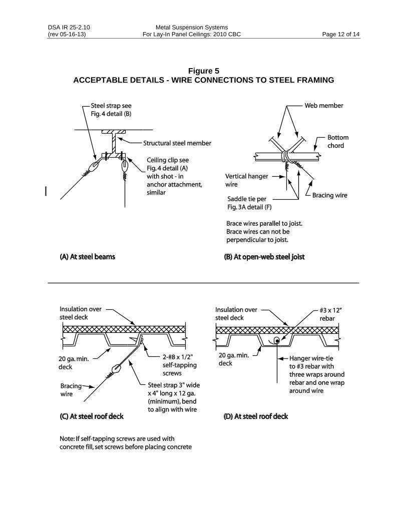
Figure 5
ACCEPTABLE DETAILS - WIRE CONNECTIONS TO STEEL FRAMING

DSA IR 25-2.10 Metal Suspension Systems (rev 05-16-13) For Lay-In Panel Ceilings: 2010 CBC Page 13 of 14
Figure 6
ACCEPTABLE DETAILS - WIRE CONNECTIONS TO STEEL DECK

DSA IR 25-2.10 Metal Suspension Systems (rev 05-16-13) For Lay-In Panel Ceilings: 2010 CBC Page 14 of 14
Figure 7
ACCEPTABLE LOCATION OF EXPANSION JOINTS IN EXITWAYS