irrigation engineering by sandeep jyani sir · 2019-06-20 · irrigation •irrigation is defined...
TRANSCRIPT

Irrigation EngineeringBy Sandeep Jyani Sir
20-06-2019

IRRIGATION• Irrigation is defined as the process of artificial supply
of water to soil for raising crops.
• It is a science of planning and designing an efficient, low-cost, economic irrigation system tailored to fit natural conditions.
• It is the engineering of controlling and harnessing the various natural sources of water, by constructing dams and reservoirs, canals and headworks, and finally distributing the water to the agricultural fields.
• Irrigation engineering includes the study and design of works in connection with river control, drainage of waterlogged areas and generation of hydroelectric power.
2Civil Engineering by Sandeep Jyani

Necessity of Irrigation?
• In adequate rainfall
• Uneven distribution of rainfall
• Increase in crop yield
• Growing perennial crops (exp- sugarcane)
• Growing 2-3 crops in a year
• Prevention from drought and famine condition
3Civil Engineering by Sandeep Jyani

Advantages
• Increase in crop yield
• Prevention from drought and famine conditions
• Elimination of mixed cropping
4Civil Engineering by Sandeep Jyani

Disadvantages of Irrigation
• Different crops require different type of field preparation, watering and manuring, since it will be difficult to satisfy the need of both the crops simultaneously in the same field , it will cause low yield
• Water logging
• Intense irrigation results in cold and damp environment which may cause disease like dengue and malaria
• Ground water pollution due to percolation of fertilizers
5Civil Engineering by Sandeep Jyani

Direct Advantages
• Power generation
• Transport/Navigation
• Ground water recharge
• Domestic and industrial water supply
• Flood control
• Employment generation
6Civil Engineering by Sandeep Jyani

IRRIGATION TECHNIQUES
7
Irrigation is broadly classified as
1. Surface Irrigation➢ Flow Irrigation - i) Perennial Irrigation
ii) Inundation/Flood Irrigation
➢ Lift Irrigation
2. Sub Surface Irrigation➢ Natural Irrigation
➢ Artificial Irrigation
Civil Engineering by Sandeep Jyani

SURFACE IRRIGATIONIn this technique water flows and spreads over the surface of the land. Varied quantities of water are allowed on the fields at different times. Therefore, flow of water under surface irrigation comes under wobbly flow.
Factors involved in surface irrigation are:• Surface slope of the field
• Roughness of the field surface
• Depth of water to be applied
• Length of run and time required
• Size and shape of water-course
• Discharge of the water-course• Field resistance to erosion
8Civil Engineering by Sandeep Jyani

TYPES OF SURFACE IRRIGATION1. FLOW IRRIGATION
• If the water is available at higher elevation and it is supplied to lower level under action of gravity, it is called as flow irrigation.
2. LIFT IRRIGATION
• If the water is lifted by some mechanical or manual means and then supplied to the agricultural field, it is called as lift irrigation.
• It is costlier than flow irrigation.
• Eg. Tubewell, pumpwell etc.9Civil Engineering by Sandeep Jyani

TYPES OF FLOW IRRIGATION
1. PERENNIAL IRRIGATION
➢ If a constant and continuous water is supplied to the agriculture field as per requirement of crops throughout the crop period, it is called as Perennial Irrigation.
➢ Types of Perennial Irrigation
A. Direct Irrigation – Eg. Canal
B. Storage Irrigation – Eg. Dams and Channels
10Civil Engineering by Sandeep Jyani

TYPES OF FLOW IRRIGATION
2. INUNDATION/FLOOD IRRIGATION
➢ In this type of irrigation, the soil is kept submerged and fully flooded with water, for saturation of land.
➢ Usually practiced in delta regions wherever the stream water level during the flood is sufficiently high to provide water to the land by flow, or partly by flow and lift.
11Civil Engineering by Sandeep Jyani

SUB SURFACE IRRIGATION
• In this type of irrigation, water does not actually wet the surface of soil rather it flows underground and nourishes the plant roots by capillarity.
• Types of sub surface irrigation
1. Natural sub surface irrigation
2. Artificial sub surface irrigation
12Civil Engineering by Sandeep Jyani

SUB SURFACE IRRIGATION
1. Natural sub surface irrigation
➢Water seeping through channels and water bodies may irrigate crops grown on the lower area of capillarity.
2. Artificial sub surface irrigation
➢Water is directly supplied to the root zone of the plants by network of perforated pipe laid below the soil surface.
13Civil Engineering by Sandeep Jyani

IRRIGATION TECHNIQUES
Irrigation technique is broadly classified as
1. Free flooding /Ordinary irrigation
2. Border irrigation
3. Check flooding
4. Basin irrigation
5. Furrow irrigation and uncontrolled flooding
6. Sprinkler irrigation
7. Drip irrigation
14Civil Engineering by Sandeep Jyani

FREE FLOODING IRRIGATION
• This flooding system of irrigation is being used from ancient times.
• Flooding method consists in applying the water by flooding the land of rather smooth and flat topography.
• In free flooding method, water is applied to the land from field ditches without any check or guidance to the flow.
• It is suitable for rolling terrain.
• It is most suitable for close growing crops and pasture.
15Civil Engineering by Sandeep Jyani

BORDER IRRIGATION
• In this method the field is leveled and divided into small beds surrounded by bunds of 15 to 30 cm high. Small irrigation channels are provided between two adjacent rows of beds.
• The length of the bed varies from 30 meters for loamy soils to 90 meters for clayey soils. The width is so adjusted as to permit the water to flow evenly and wet the land uniformly.
16Civil Engineering by Sandeep Jyani

BORDER IRRIGATION
• For high value crops, the beds may be still smaller especially where water is costly and not very abundant.
• This method is adaptable to most soil textures except sandy soils and is suitable for high value crops. It requires leveled land.
• Though the initial cost is high requires less labour and low maintenance cost.
17Civil Engineering by Sandeep Jyani

CHECK FLOODING IRRIGATION• In this method, relatively level plots are
enclosed by small leeves or embankments.
• Irrigation water enters the closed area and subsequently floods it.
• Check flooding method is very suitable for soils having high permeability. The reason is that the water quickly spreads over the entire area before it goes deep, below the root zone depths, into the ground and joins the water table. Thus, the water loss due to infiltration is prevented or reduced.
• It is best adopted for heavy soils.
18Civil Engineering by Sandeep Jyani

BASIN IRRIGATION• Basin irrigation is common practice
of surface irrigation.
• This method is employed for watering orchards.
• It is useful especially in regions with layouts of small fields.
• If a field is level in all directions, is encompassed by a dyke to prevent runoff, and provides an undirected flow of water onto the field, it is herein called a basin.
• A basin is typically square in shape but exists in all sorts of irregular and rectangular configurations.
19Civil Engineering by Sandeep Jyani

FURROW IRRIGATION
• Row crops such as potatoes, cotton, sugarcane, vegetable etc. can be irrigated by furrow method. Water is allowed to flow in furrow opened in crop rows.
• It is suitable for sloppy lands where the furrows are made along contours. The length of furrow is determined mostly by soil permeability.
• It varies from 3 to 6 meters. In sandy and clay loams, the length is shorter than in clay and clay loams. Water does not come in contact with the plant stems.
• There is a great economy in use of water.
• Sometimes, even in furrow irrigation the field is divided into beds having alternate rides and furrows. On slopes of 1 to 3 percent, furrow irrigation with straight furrows is quite successful.
20Civil Engineering by Sandeep Jyani

SPRINKLER IRRIGATION• In the sprinkler technique of irrigation, water is sprinkled
into the air and allowed to fall on the ground surface just like rainfall.
• The spray is done by the flow of water under pressure through small orifices or nozzles
• The pressure is generally obtained by pumping through proper selection of nozzle sizes, operating pressure and sprinkler spacing the amount of irrigation water required to refill the crop root zone can be applied almost uniform at the rate to suit the infiltration rate of soil.
• In agriculture, almost all crops are suitable for sprinkler irrigation system except crops such as paddy and jute.
• The dry crops, vegetables, flowering crops, orchards, plantation crops like tea, coffee are all suitable and can be irrigated through sprinklers techniques of irrigation.
21Civil Engineering by Sandeep Jyani

SPRINKLER IRRIGATION• The sprinkler irrigation system is
effective for irrigation on uneven lands and on shallow soils.
• It is also suitable to coarse sandy terrain where the percolation loss is more and where as a consequence, the frequency of irrigation required is more.
• The sprinkler irrigation system is appropriate in rising and falling land where land shaping is expensive or technically not practicable.
• Sprinkler irrigation system can also be exposed in hilly regions where plantation crops are grown.
• Irrigation efficiency is about 80%.
22Civil Engineering by Sandeep Jyani

SPRINKLER IRRIGATION• Evaporation loss is high.
• Causes interference in farming operations due to network system.
• Winds may disturb sprinkler pattern
• High initial cost.
• Requires large electrical power and constant water supply.
• Cannot be used for crops which require frequent and large depth of water like paddy.
23Civil Engineering by Sandeep Jyani

DRIP IRRIGATION• It is a latest advancement over other methods.
• In this method irrigation water is conveyed on the surface in 12 to 16 mm diameter tubing’s fed from large feeder pipes.
• The water is allowed to drip or trickle slowly through the nozzle or orifices at practically zero pressure. In this way the soil in the root-zone of crops is constantly kept wet.
• Water is applied at very low rate 2-10 litres/hour.
• By using this method crops can be grown successfully over the saline lands also.
• Irrigation efficiency is 90%.
• This method has been found to be of great value in reclaiming and developing desert and arid areas.
24Civil Engineering by Sandeep Jyani

DRIP IRRIGATION
• It helps in optimum utilization of irrigation water by reducing percolation and evaporation losses on one hand and by maintaining appropriate water content in the root-zone of plants.
• There is no chance of land getting waterlogged and thereby becoming saline or alkaline.
• Crop yield is substantially increased.
• It makes possible to go cash crops.
25Civil Engineering by Sandeep Jyani

DRIP IRRIGATION
• The fields do not get infested with weeds and pest due to non-availability of excess water.
• It helps in economical use of fertilizers since they are applied along with irrigation water in solution with it.
• The fields do not get eroded or degraded since there is no excessive use of water on the fields.
• The main drawback of this method is its high cost.
26Civil Engineering by Sandeep Jyani

Quality of Irrigation water
1. Sediment: • Effect of Sediment on the quality of irrigation water
depends on the nature of sediment and characteristics of the soil receiving the water.
• If sediment contains large amount of plant nutrition and it comes from fertile area then it is quite beneficial, particularly for agriculture area which has low content of plant nutrient and a very low water holding capacity
• If a sediment is not rich in plant nutrient and it is deposited on the surface, it will reduce permeability of the soil and will make irrigation more difficult
27Civil Engineering by Sandeep Jyani

Quality of Irrigation water2. Concentration of Salt:
• Salts present in water increases osmotic pressure of the soil solution causing high soil moisture stress in the root zone which affects the growth of crops and yield of the crops
• Bad effects of the salts depends upon the salt concentration left in the soil
𝑪𝒔 =𝑪𝑸
𝑸 − (𝑪𝒖 − 𝑹𝒆𝒇𝒇)(𝒑𝒑𝒎 𝒐𝒓 𝒎𝒈/𝑳)
• Cs= salinity concentration of the soil solution• C= concentration of the salts• Q= amount of water applied• Cu= consumptive use of water by crops• Reff= effective rainfall/ amount of water in root zone • If Cs >700 ppm-harmful to some crops• If Cs>2000 ppm, harmful to all crops
28Civil Engineering by Sandeep Jyani

Concentration of Salt
Sr No. Classification Electrical conductivity 𝝁𝑴𝒉𝒐/𝒄𝒎
Uses
1 Low saline water <250 For all crops
2 Medium Saline water
250-750 Normal salt tolerant plants can be grown
if leaching is done
3 High saline water 750-2250 High salt tolerant plants can be grown
with special measures
4 Very high saline water
>2250 Not suitable
29Civil Engineering by Sandeep Jyani
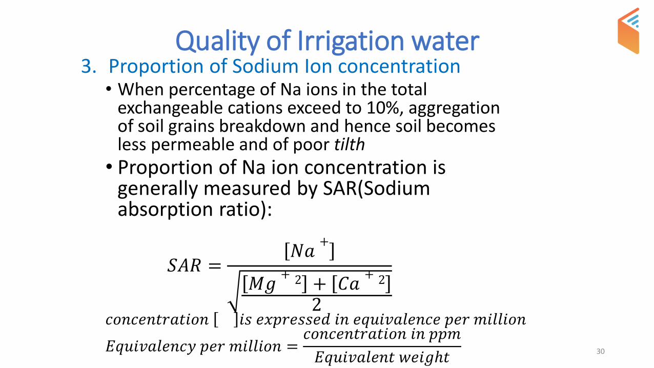
Quality of Irrigation water3. Proportion of Sodium Ion concentration
• When percentage of Na ions in the total exchangeable cations exceed to 10%, aggregation of soil grains breakdown and hence soil becomes less permeable and of poor tilth
• Proportion of Na ion concentration is generally measured by SAR(Sodium absorption ratio):
𝑆𝐴𝑅 =𝑁𝑎
+
𝑀𝑔+ 2 + 𝐶𝑎
+ 2
2𝑐𝑜𝑛𝑐𝑒𝑛𝑡𝑟𝑎𝑡𝑖𝑜𝑛 𝑖𝑠 𝑒𝑥𝑝𝑟𝑒𝑠𝑠𝑒𝑑 𝑖𝑛 𝑒𝑞𝑢𝑖𝑣𝑎𝑙𝑒𝑛𝑐𝑒 𝑝𝑒𝑟 𝑚𝑖𝑙𝑙𝑖𝑜𝑛
𝐸𝑞𝑢𝑖𝑣𝑎𝑙𝑒𝑛𝑐𝑦 𝑝𝑒𝑟 𝑚𝑖𝑙𝑙𝑖𝑜𝑛 =𝑐𝑜𝑛𝑐𝑒𝑛𝑡𝑟𝑎𝑡𝑖𝑜𝑛 𝑖𝑛 𝑝𝑝𝑚
𝐸𝑞𝑢𝑖𝑣𝑎𝑙𝑒𝑛𝑡 𝑤𝑒𝑖𝑔ℎ𝑡30

SAR values
Sr No. Classification SAR Uses
1 Low sodium water 0-10 For all crops on all soils
2 Medium sodium water
10-18 Can be used in coarse grain soil
3 High sodium water 18-26 Can be used if leaching is done and
requires good draingage system
4 Very high sodium water
>26 Not suitable
31Civil Engineering by Sandeep Jyani

Que. Irrigation water has following characteristics:
Concentration of Na, Ca and Mg are 22, 3, 1.5ppm respectively and electrical conductivity is 200 micro Mho/cm. Classify the irrigation water?
32Civil Engineering by Sandeep Jyani

Que. 1 Irrigation water has following characteristics:
Concentration of Na, Ca and Mg are 22, 3, 1.5ppm respectively and electrical conductivity is 200 micro Mho/cm. Classify the irrigation water?
33
𝑺𝑨𝑹 =𝟐𝟐
𝟑 + 𝟏. 𝟓𝟐
𝑺𝑨𝑹 =𝑵𝒂
+
𝑴𝒈+ 𝟐 + 𝑪𝒂
+ 𝟐
𝟐
𝑺𝑨𝑹 = 𝟏𝟒. 𝟔𝟕
𝑴𝒆𝒅𝒊𝒖𝒎 𝒔𝒐𝒅𝒊𝒖𝒎 𝒂𝒏𝒅 𝒍𝒐𝒘 𝒔𝒂𝒍𝒊𝒏𝒆 𝒘𝒂𝒕𝒆𝒓
Civil Engineering by Sandeep Jyani

SOIL MOISTURE AND PLANT RELATIONSHIP
34
Soil Moisture:
→ Water held in the voids of the soil above the water table is called as ‘’Soil Moisture’’
→ Water holding capacity of the soil
→water holding capacity of the soil mainly depends on
(i) Porosity of soil n =
𝒏 =𝑽𝒗
𝑽→ Which is physical property of soil
(ii) Size of voids: Moisture holding capacity of the soil largely depends on size of the voids.
Civil Engineering by Sandeep Jyani

SOIL MOISTURE AND PLANT RELATIONSHIP
35
• Size of the voids can be divided into 2 groups
Capillary Voids :• Small Voids• They hold water due to capillarity
and prevent it from getting drained of under gravity
• It induces greater water holding capacity
• Ex: clay
Non – Capillary Voids:-• Large Voids • They don’t hold water tightly
hence large part of water held at saturation is drained off under gravity
• It induces better drainage and accretion
• Ex:- Sand
Civil Engineering by Sandeep Jyani

• Note: Ideal soil, for irrigation is thatwhich has nearly equal distribution ofsmall voids and large voids. Such thatsmall voids provides adequate waterholding capacity whereas large voidprovides better aeration & easyextraction of water from the soil Ex:-Loam soil, i.e mixture of sand & clay
36Civil Engineering by Sandeep Jyani

Classification of Soil WaterWater in the voids of the soil can be divided into 3 parts;
1. Gravity Water
• → It is that water which is not held by the soil butdrain out under the action of gravity
• → it remains in the soil for a short time period (1 to3 days) till the time it is required to drain out
• →it prevents circulation of air in the soil hence it isharmful to the crops if present for longer duration
37Civil Engineering by Sandeep Jyani

Classification of Soil Water2. Capillary Water
• → It is that pat of water which is retained inthe soil after gravity water is drained offand it can be absorbed by the plant roots.
• → This water held in the soil by surfacetension between the soil particles plantroots gradually absorb capillary waterhence it is main source of water for plantgrowth, these fore it is also called as‘Available water’
38Civil Engineering by Sandeep Jyani

Classification of Soil Water3. Hygroscopic Water
• → Hygroscopic water is that water which is absorbed by the soil particles from the atmosphere and it is held very tightly by the soil particles, therefore if cannot be extracted by plant roots.
39Civil Engineering by Sandeep Jyani

Soil Moisture Tension & Soil Moisture Stress• → Soil moisture tension is defined as force per unit area that
must be exerted in order to extract water from the soil.
• → Soil moisture tension is usually expressed in terms of Atmosphere (i.g. pressure)
• 𝑆𝑜𝑖𝑙 𝑚𝑜𝑖𝑠𝑡𝑢𝑟𝑒 𝑡𝑒𝑛𝑠𝑖𝑜𝑛 ∝1
𝑚𝑜𝑖𝑠𝑡𝑢𝑟𝑒 𝑐𝑜𝑛𝑡𝑒𝑛𝑡
• For a given soil, soil moisture tension SMT is inversely proportional to moisture content
• If we know, SMT at various moisture content then we can determine how much water is available for plants and what amount of water must be added to the soil for the purpose of irrigation
• Soil Moisture Stress is sum of soil moisture tension (SMT) & osmotic pressure
• Soil moisture tension (SMT) at field capacity ranges between 1/10 ATM (sand) to 1/3 ATM (clay)
40Civil Engineering by Sandeep Jyani

Soil moisture Constants and Soil moisture Contents
41
GW
CW
HW
Soil
Wilting Point (∅)
Optimum moisture content (M0)
Field capacity (Fc)
Saturation capacity SMT = 0 ATM
SMT = 1/10 – 1/3 ATM
Readily available moisture
Available moisture content
SMT = 7 – 32 ATM
Civil Engineering by Sandeep Jyani
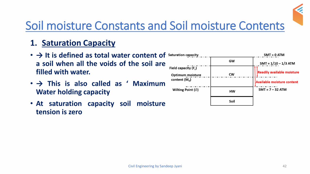
Soil moisture Constants and Soil moisture Contents
42
1. Saturation Capacity
• → It is defined as total water content ofa soil when all the voids of the soil arefilled with water.
• → This is also called as ‘ MaximumWater holding capacity
• At saturation capacity soil moisturetension is zero
Civil Engineering by Sandeep Jyani

2. Field capacity (Fc)• → it is the maximum water which can be held by the soil against gravity
• → It depends on porosity and capillarity
• → Moisture content at field capacity includes hygroscopic water &capillary water
• Note: Irrigation water has to be supplied to the crops when themoisture level falls ‘below wilting point’
𝐹𝑐 =𝑤𝑡 𝑜𝑓 𝑤𝑎𝑡𝑒𝑟 𝑟𝑒𝑡𝑎𝑖𝑛𝑒𝑑 𝑖𝑛 𝑐𝑒𝑟𝑡𝑎𝑖𝑛 𝑣𝑜𝑙𝑢𝑚𝑒 𝑜𝑓 𝑠𝑜𝑖𝑙
𝑤𝑡 𝑜𝑓 𝑠𝑎𝑚𝑒 𝑣𝑜𝑙𝑢𝑚𝑒 𝑜𝑓 𝑑𝑟𝑦 𝑣𝑜𝑙𝑢𝑚𝑒 𝑜𝑓 𝑠𝑜𝑖𝑙
43Civil Engineering by Sandeep Jyani

3. Wilting point /permanent wilting point (Ø)
• → Wilting point is the moisture content below whichplant can no longer extract moisture from the soil for itsgrowth
• → at this moisture content plant leaves will wilt
• → permanent wilting point depends on nature of soil
• → permanent wilting point is the lower limit of capillarywater & upper limit of Hygroscopic water.
44Civil Engineering by Sandeep Jyani

4. Available Moisture Content
• → it is difference of field capacity (Fc) andwilting point (Ø), it is the water available forthe growth of crops
• → it is also called as ‘Maximum storage capacityof the soil’.
45Civil Engineering by Sandeep Jyani

5. Readily Available Moisture Content
• → It is that portion of available moisture which ismost easily extracted by the plants and such a limit iscalled ‘Optimum moisture content’ (Mo)
• → In absence of data, we can assume readily availablemoisture content = 75% of available moisture content
46Civil Engineering by Sandeep Jyani

Soil Moisture deficiency/Field Moisture deficiency
• Soil moisture deficiency is the amount of water which is to be added to the soil such that moisture content is raised to field capacity.
• For healthy or optimum growth of plants, moisture is allowed to fall only up to M0 and not up to wilting point Ø
47
Growth rate
Ø M0 Fc
Civil Engineering by Sandeep Jyani

Moisture Equivalent
• Moisture equivalent is defined as percentage of moisture retained in 10 mm thick saturated sample of soil subjected to a centrifugal force of 1000g for a period of 30 minute .
• It can be quickly determined in laboratory and gives very good indication of Fc
48Civil Engineering by Sandeep Jyani

1/3rd Atmosphere moisture point
• It is percentage of moisture retained in soil sample when placed on a porous plate subjected to atmosphere pressure of 1/3rd atmosphere.
• It also provides a good estimate of Fc.
49Civil Engineering by Sandeep Jyani

Depth of water held in root zoneFor Ease in calculation, water present in voids of the soil needs to be expressed as depth of water
• Let , root zone depth = ‘𝐷’ m
• Specific wt. of dry soil = 𝜸d
• Cross-sectional area of the soil considered = A
• Equivalent depth of water present in voids of the soil = 𝑑 m
𝐹𝑐 =𝑤𝑡 𝑜𝑓 𝑤𝑎𝑡𝑒𝑟 𝑖𝑛 𝑐𝑒𝑟𝑡𝑎𝑖𝑛 𝑣𝑜𝑙𝑢𝑚𝑒 𝑜𝑓 𝑠𝑜𝑖𝑙
𝑤𝑡 𝑜𝑓 𝑠𝑎𝑚𝑒 𝑣𝑜𝑙𝑢𝑚𝑒 𝑜𝑓 𝑠𝑜𝑖𝑙
⇒ 𝐹𝑐 =𝐴 × 𝑑 × 𝜸w
𝐴 × 𝐷 × 𝜸d
⇒ 𝑑 =𝜸d
𝜸w×
𝑫 × 𝑭𝒄
50Civil Engineering by Sandeep Jyani

• If is the depth of water stored in the root zone for full field capacity but, this entire depth of water cannot be extracted by the plants, hence available moisture content will be given as;
𝑑 =𝜸d
𝜸w×
𝑫 × (𝑭𝒄 − Ø)
• Equivalent depth of water readily available,
𝑑 =𝜸d
𝜸w×
𝑫 × (𝑭𝒄 − M0)
51Civil Engineering by Sandeep Jyani

Chapter: Water Requirement of Crop
• Water requirement of a crop is the total water required by it from the time it is sown to the time it is harvested.
• Note:→ Depending on type of climate type of soil, method of cultivation, rain fall and etc, water requirement will vary with the crop as well as from place to place
52Civil Engineering by Sandeep Jyani

53
First Watering
Last Watering
Sown
HarvestedCrop Period
Base Period
Civil Engineering by Sandeep Jyani

Water requirement of crop• Crop period: it is the time interval between instant of sowing to the instant
of harvesting. It represents the total time during which crop was present in the field.
• Base period: it is time interval between first watering before sowing the last watering before harvesting.
• Note:→ In reality, crop period > Base period, but theoretically they areapproximate taken same and even terms are used interchangeably.
54Civil Engineering by Sandeep Jyani

Water requirement of crop
• Delta (∆):- ∆ is defined as total depth of water in cm required by a crop during the base period.
Que. 2 If a crop requires 7 cm water at every 25 days if base period of the crop is 125 days determine ∆ for the crop…?
55Civil Engineering by Sandeep Jyani

Water requirement of crop
Duty (D): Duty is defined as area irrigated in hectare by 1 cumec of water flowing continuously for the duration of base period.
Duty is expressed as, D = 300 ha/cumec
• By knowing Duty of water & area to be irrigated for growinga particular crop, required discharge can be calculated.
• Also by knowing total available discharge and duty of water,area which can be irrigated can be determined.
56Civil Engineering by Sandeep Jyani

Important note1. Since quantity of water delivered to the field is different from that enters
the main canal, therefore, Duty of water at the head of the field is different from Duty at the head of main canal
57
let, 2 cumec of water is released in the main canalwhich irrigates a field area of 1000 hectare.
∴ 𝑮𝒓𝒐𝒔𝒔 𝒅𝒖𝒕𝒚 =𝟏𝟎𝟎𝟎 𝒉𝒂
𝟐𝒄𝒖𝒎𝒆𝒄= 500 ha/cumec
since half of the water is lost in the transit and therefore 1 cumec of water has only reached to the head of the field to irrigate same field area of 1000 ha.
∴ 𝑵𝒆𝒕 𝒅𝒖𝒕𝒚 =𝟏𝟎𝟎𝟎 𝒉𝒂
𝟏 𝒄𝒖𝒎𝒆𝒄= 1000 ha/cumec
Duty increases from the main canal to the field
If the place of duty measured is not mentioned then it should be assumed as Duty of the field.

Relationship between Duty (D) and Delta ∆• Let ‘D’ hectare area is irrigated by supplying 1 m3/sec of water for the base period of
‘B’ days such that total water stored in the root zone is ∆ m
• Therefore, volume of water supplied = B Days x 1 m3/sec
= B x 24x60x60 sec x 1 m3/sec
= 68400 B m3 … (1)
• Amount of water stored = D (ha) x ∆ (m)
= D x 104 m2 x ∆ m
=D x ∆ 104 m3 …..(2)
Equating (1) and (2),
D x ∆ 104 m3 = 68400 B m3
=> D x ∆ = 8.64 B
58
D =ha/cumec ∆ = m B= days

Que. Find ∆ for a crop if duty for the base period of 120days is 1500 hectare/cumec
Ans: D x ∆ = 8.64 B
=> ∆ = 8.64 𝑩
𝑫
=> ∆ = 8.64 𝟏𝟐𝟎
𝟏𝟓𝟎𝟎
=> ∆ = 0.6912 m
59Civil Engineering by Sandeep Jyani

Que. A canal was designed for supplying irrigation water of 1000 hectares of area, growing rice of base period 140 days and having a ∆ of 130 cm. If same canal water is used to irrigate wheat of base period 119 days having ∆ of 50cm, area which can be irrigated is…?
Ans: Home work!!
60Civil Engineering by Sandeep Jyani

Crops and Seasons of India
1. Khareef crops/Summer Crops:• (April – September ) & ‘Summer Crop’• Rice, Jowar, Bajra, Maize, Ground nut, cotton
2. Rabi Crops:• (October – March) & ‘ winter crop’• Wheat, Gram, Mustard, Potato, Barley
3. Perennial Crops:• (300-360) days
4. Zaid Crops• Fruits and vegetables (March-June)
61Civil Engineering by Sandeep Jyani

Important Definition
1. Crop ratio/Rabi-Kharif ratio
• Crop = 𝑨𝒓𝒆𝒂 𝒊𝒓𝒓𝒊𝒈𝒂𝒕𝒆𝒅 𝒊𝒏 𝑹𝒂𝒃𝒊 𝒔𝒆𝒂𝒔𝒐𝒏
𝑨𝒓𝒆𝒂 𝒊𝒓𝒓𝒊𝒈𝒂𝒕𝒆𝒅 𝒊𝒏 𝑲𝒉𝒂𝒓𝒊𝒇 𝒔𝒆𝒂𝒔𝒐𝒏= 2 (approx)
2. Paleo irrigation• It is defined as watering done prior to the sowing
of crops.
• It is done to make area suitable for sowing as it becomes very dry and to add sufficient moisture to the soil which would be required for initial growth
62Civil Engineering by Sandeep Jyani

Important Definition 3. Kor watering, Kor depth, Kor Period:
• Kor Watering is the first watering after sowing of crops when crop is few ‘cm’ high
• This irrigation depth is the maximum of all the waterings and this depth is called as KOR depth
• The portion of Base period in which KOR watering is needed is called as ‘Kor period’
4. Capacity factor:
= 𝐌𝐞𝐚𝐧 𝐬𝐮𝐩𝐩𝐥𝐲 𝐝𝐢𝐬𝐜𝐡𝐚𝐫𝐠𝐞 𝐟𝐨𝐫 𝐚 𝐜𝐚𝐧𝐚𝐥 𝐟𝐨𝐫 𝐚 𝐜𝐞𝐫𝐭𝐚𝐢𝐧 𝐝𝐮𝐫𝐚𝐭𝐢𝐨𝐧
𝐌𝐚𝐱𝐢𝐦𝐮𝐦 𝐝𝐢𝐬𝐜𝐡𝐚𝐠𝐞 𝐜𝐚𝐫𝐫𝐲𝐢𝐧𝐠 𝐜𝐚𝐩𝐚𝐜𝐢𝐭𝐲 𝐨𝐟 𝐜𝐚𝐧𝐚𝐥
= 𝐐𝐫𝐞𝐪𝐮𝐢𝐫𝐞𝐝
𝐐𝐝𝐞𝐬𝐢𝐠𝐧𝐞𝐝
63Civil Engineering by Sandeep Jyani

Important Definition 5. Time Factor
Time Factor = No.of days canal has actually run
No.of days of irrigation period
6. Crop Calendar
Crop calendar is a tool that provides information about planting, sowing, and harvesting period of locally adopted crops in an area.
64

Important Definition 7. Gross Command Area (GCA)
• It is the total area with in the limit of an irrigation project.
• It includes cultivable as well as non-cultivable area like road, Building, Pond etc.
65Civil Engineering by Sandeep Jyani

Important Definition 8. Cultivable Command Area (CCA);
• It is that portion of GCA which is cultivable and it denotes the area on which actually cultivation is to be done.
• In absence of data we may assume, CCA = 80% of GCA.
66Civil Engineering by Sandeep Jyani

Important Definition 9. Intensity Of Irrigation /Annual Intensity Of Irrigation
• Intensity of Irrigation = sum of seasonal intensity of irrigation in a year.
• Seasonal intensity of Irrigation is that percentage of CCA on which actually the irrigation is done in a particular season.
67
ANNUAL INTENSITY = 90%+70% = 160%
Civil Engineering by Sandeep Jyani

Important Definition 10. Irrigation efficiency;• In general,
irrigation efficiency = Water available for use
water applieda) Water conveyance efficiency (nc)
NC = 𝑤𝑓
𝑤𝑟
× 100
where, wr is water released from river reservoir for the field.wf is water given to the field
This efficiency account for water which possess seepage loss & evaporating loss during conveyance from river (or) reservoir to the field.
68Civil Engineering by Sandeep Jyani
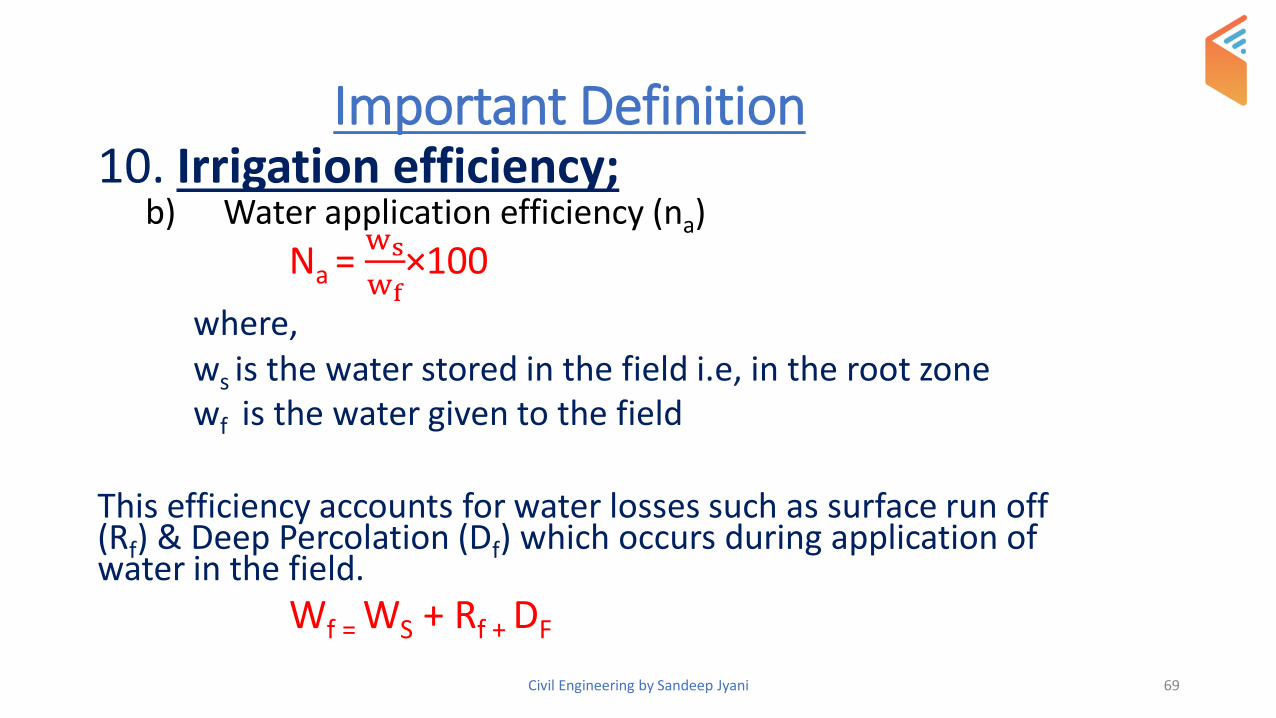
Important Definition 10. Irrigation efficiency;
b) Water application efficiency (na)
Na = ws
wf×100
where, ws is the water stored in the field i.e, in the root zonewf is the water given to the field
This efficiency accounts for water losses such as surface run off (Rf) & Deep Percolation (Df) which occurs during application of water in the field.
Wf = WS + Rf + DF
69Civil Engineering by Sandeep Jyani

Important Definition 10. Irrigation efficiency;
c) Water use efficiency (nu)
Nu = Wu
wf×100
where, wf is the water given to the fieldwu water use consumptivelywu = leaching requirement + presowing requirement + water stored
70Civil Engineering by Sandeep Jyani

Important Definition 10. Irrigation efficiency;
d) Water storage efficiency (ns)
Ns = ws
wn× 100
where,
ws is the water stored in the field, i.e, in the root zone
wn is the amount of water to be stored in the field such that moisture content is raised to field capacity (FC)
wn is the total water required up to Fc i.e., available moisture content before irrigation.
71Civil Engineering by Sandeep Jyani

IRRIGATION REQUIREMENTS OF CROP
• CONSUMPTIVE IRRIGATION REQUIREMENT➢It is the amount of water required to meet evapotranspiration needs of crop
during its full growth
➢It is denoted by CIR
CIR = CU – Reff
72Civil Engineering by Sandeep Jyani

IRRIGATION REQUIREMENTS OF CROP
• NET IRRIGATION REQUIREMENT➢It is the amount of water required to be delivered at the field to meet CIR, i.e.
evapotranspiration as well as water required for presowing and leaching.
➢It is denoted by NIR
NIR = CIR + PRESOWING REQUIREMENT + LEACHING REQUIREMENT
73Civil Engineering by Sandeep Jyani

IRRIGATION REQUIREMENTS OF CROP
• FIELD IRRIGATION REQUIREMENT➢It is the amount of water required by the crop in the field plus
amount of water lost in application.
➢It is denoted by FIR
FIR = Net Irrigation RequirementWater application efficiency
FIR = NIR/na
74Civil Engineering by Sandeep Jyani
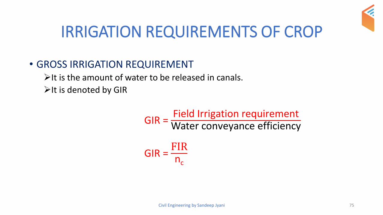
IRRIGATION REQUIREMENTS OF CROP
• GROSS IRRIGATION REQUIREMENT➢It is the amount of water to be released in canals.
➢It is denoted by GIR
GIR = Field Irrigation requirementWater conveyance efficiency
GIR = FIRnc
75Civil Engineering by Sandeep Jyani

CONSUMPTIVE USE
• It is defined as amount of water required to meet the water loss through evapotranspiration in any specified time.
• It has two elements
➢Transpiration
➢Evaporation
76Civil Engineering by Sandeep Jyani

CONSUMPTIVE USE
➢TRANSPIRATION –
In this, only a small portion of water absorbed by the roots is retained in the plants and rest of the water after performing task is lost to the atmosphere.
➢EVAPORATION –
Water from adjacent soil passes into the atmosphere in the form of vapour.
77Civil Engineering by Sandeep Jyani

CONSUMPTIVE USE
➢FACTORS AFFECTING CONSUMPTIVE USE:
1. Temperature
2. Wind velocity
3. Relative humidity
4. Day light hours
5. Intensity of sunlight
6. Type of crop
7. Soil moisture depletion
78Civil Engineering by Sandeep Jyani

EVAPOTRANSPIRATION
1. POTENTIAL EVAPOTRANSPIRATION
• If sufficient moisture is always available to completely meet the need of vegetation and fully covering the area then it is termed as potential evapotranspiration.
• It depends upon climatic factors.
2. ACTUAL EVAPOTRANSPIRATION
• The real evapotranspiration that is occurring in a specified situation is termed as actual evapotranspiration.
If the water supply to the plants is adequate, soil moisture will be at field capacity then AET = PET
79Civil Engineering by Sandeep Jyani

EVAPOTRANSPIRATION
• If the water supply to the plants is adequate, soil moisture will be at field capacity then AET = PET
• The decrease in the ratio of AET/PET with the available moisture content depends upon the type of soil.
• Capillary water is large in case of clay, so if water content is below Fc
even when the water can be easily taken up by plants so AET remains close to PET.
80Civil Engineering by Sandeep Jyani

CANAL DESIGN
• On account of erosion in catchment and drainage basin, rivers receive huge quantity of sediment having fine silt, coarse sand , a portion of which enters into a canal also.
• Design of canal mainly depends on quantity of silt in the water and type of boundary surface of the channel.
81Civil Engineering by Sandeep Jyani

CANAL DESIGN
1. Rigid boundary channel
• In this the surface of channel is lined.
• Quantity of silt transported by such channels remains more or less same that has entered at the head of the channel.
• In such channel velocity of flow is high which does not allows deposition of silt.
• Therefore, these channels do not have problem of silt transport.
82Civil Engineering by Sandeep Jyani

CANAL DESIGN2. Unlined channels
• In this the quantity of silt varies from section to section due to scouring of bed and sides of the channels as well as due to silting.
• If velocity is too low then silting may take place whereas if velocity is very high scouring may take place.
NOTE : Both of these phenomenon leads to modification of cross-section of channel. Scouring lowers full supply level which causes loss of command area. It may also cause breaching of canal banks and failure of foundation irrigation structure, whereas silting may cause reduction in discharge capacity of the channel.
83Civil Engineering by Sandeep Jyani

CANAL DESIGN
3. Unlined Alluvial Channels
• These should be designed for such a velocity such that neither bed and sides are scoured nor silt is deposited and a stable channel section is obtained such channels are called as stable channels or regime.
• The velocity of flow which will keep silt in suspension & will not scour the bed and sides of the channel, it is called as non silting and non- scouring velocity.
84Civil Engineering by Sandeep Jyani

DESIGN OF REGIME CHANNEL
Basically two methods are used for design of Regime channel
1. Kennedy’s Theory (1595)
2. Lacey’s theory
85Civil Engineering by Sandeep Jyani

KENNEDY’S THEORYAccording to Kennedy,
1. Eddies are generated due to friction between water and channel surface.
2. Silt supporting power of a channel depends on eddies generated from the bed of the channel. The vertical component of these eddies tries to more than sediment upwards, while weight of the sediment tries to bring it down, Hence sediment remains in suspension.
3. Eddies generated from the sides were neglected because they are horizontal for the greater part and hence they have very little silt supporting power.
• Kennedy introduced the term critical velocity (Vo) which will keep channel free from silting & scouring.
86Civil Engineering by Sandeep Jyani

KENNEDY’S THEORYVo= 0.55 my 0.64
Vo → critical velocity in m/sec
y → depth of flow in m
m → critical velocity ratio, whose value will depend on type of soil
m > I → for coarse soil (1-1.2)
m < I → for fine soil (0.7-1)
87Civil Engineering by Sandeep Jyani

DRAWBACKS OF KENNEDY’S THEORY
1. Kutter’s equation is used to determine the mean velocity of flow hence limitation of Kutter’s equation are also incorporated in Kennedy’s theory.
2. This theory involves trial & error which is time consuming.
3. Silt concentration and silt grade is not considered.
4. This theory is not universally accepted.
5. Value of ‘m’ is decided arbitrarily
6. There is no equation for bed slope or b/d ratio without which it is not possible to obtain a unique section.
88Civil Engineering by Sandeep Jyani

LACEY’S THEORY
• Lacey carried out extensive investigation on the design of stable channel in alluvium.
• He found many drawbacks in Kennedy’s theory.
• He elaborated regime concept and found that even if a channel is showing no silting and no scouring, it may not be in regime actually. He therefore differentiated between three regime conditions.
• True Regime
• Initial Regime
• Final Regime
89Civil Engineering by Sandeep Jyani

LACEY’S THEORY1. True Regime Condition
• An artificially constructed channel having certain fixed section and a certain fixed slope can behave in regime only if following conditions are satisfied.
a) Discharge is constantb) Flow is uniform c) Silt charge & silt grade is constantd) Canal is flowing through an incoherent alluvium which is of
the same grade as that of alluvium transported.e) In practice all these conditions can never be satisfied,
therefore an artificial channel can never be in True Regime.
90Civil Engineering by Sandeep Jyani

LACEY’S THEORY2. Initial Regime Condition
• It is first stage of regime attained by a channel after it is in service.
• If a channel is excavated with smaller width and flatter bed slope, then as the flow takes place in the channel, bed slope of the channel is increased due to deposition of silt on the bed to develop increased flow velocity, hence the given discharge is allowed to flow through the channel of smaller width and sides of such channel are subjected to lateral restrain and could have scoured if the bank soil would have been in true alluvium.
91Civil Engineering by Sandeep Jyani

LACEY’S THEORY2. Initial Regime Condition
• But in practice they may be grassed or may be of clayey soil, therefore they may not get eroded.
• Hence such channels will appear to be in Regime.
• They have achieved only a working stability due to rigidity of their banks, such channel are termed as ‘Channels in Initial Regime’.
• Lacey’s Theory is not applicable in initial Regime condition
92Civil Engineering by Sandeep Jyani

LACEY’S THEORY
3. Final Regime Condition:
• It is the ultimate state of Regime attained by a channel when bed slope, depth of flow & width are adjusted in order to obtain a stable channel section. This condition is called as ‘Final Regime Condition’.
• Such a channel in which all the variables are equally free to vary has the tendency to attain a semi elliptical section.
• When a channel is protected on the bed and sides with some kind of protecting material, Channel section could not be scoured and there is no possibility of change in longitudinal slope. These channel sections are said to be in ‘permanent regime’
93Civil Engineering by Sandeep Jyani

DESIGN STEPS FOR LACEY’S THEORYFor a given discharge, Q mean particle size d50 in mm
• Determine silt factor, f = 1.76 𝒅𝒎𝒎
• Determine velocity 𝝂 =𝑸𝒇𝟐
𝟏𝟒𝟎1/6
• Determine Area A = 𝑸
𝝂
• Assuming, side slope 1/2H : 1v
• Determine Perimeter P = 4.75 𝑸 (Q in m3/sec)
• Determine Bed slope;
• S = 𝟏
𝟑𝟑𝟒𝟎×
𝒇𝟓/𝟑
𝑸𝟏/𝟔
94Civil Engineering by Sandeep Jyani

DRAWBACKS OF LACEY’S THEORY
1. Lacey said that a Regime channel has a semi elliptical shape but same is not supported by his equation.
2. Regime relations do not account for amount of sediment transported by flowing water.
3. Characteristics of Regime channel are not precisely defined.
95Civil Engineering by Sandeep Jyani

COMPARISON OF KENNEDY’S AND LACEY’S THEORYKENNEDY’S THEORY LACEY’S THEORY
Trapezoidal channel Semi elliptical channel
Silt is kept in suspension due to eddies generated from bottom
Silt is kept in suspension, due to eddies generated both from side slope & the bottom i.e, throughout the perimeter.
Recommended Kutter’s equation for finding velocity.
Gave his own velocity equation.
No equation for bed slope. Gave eqn to calculate bed slope
Trial & error procedure Direct procedure
Applicable for alluvial channel Applicable for alluvial channel as well as for rivers.
96Civil Engineering by Sandeep Jyani

CANAL HEAD WORKS
• In order to divert water from the river into the canal, it is necessary to construct certain works on structures across the river & at the head of the off taking canal. These works are termed as ‘Canal Head works (or) Head works’.
• Canal Headworks are classified into 2 types;
1. Storage Headworks
2. Diversion Headworks
97Civil Engineering by Sandeep Jyani

TYPES OF DIVERSION HEADWORKSa) Temporary diversion Headwork:
• It consists of a spur (or) bund constructed across the river to raise the water level in the river and divert it into the canal.
• These bunds are constructed almost every year after the floods, because they may be damaged by the floods.
b) Permanent diversion Headwork:
• It consist of a permanent structure such as weir (or) barrage constructed across the river to raise the water level in the river and divert it into the canal.
• In our country, most of the diversion head works for important canal system are Permanent diversion headwork.
98Civil Engineering by Sandeep Jyani

LOCATION OF CANAL HEADWORK
1. Rocky stage (𝒐𝒓) Hilly stage:
• In this state, the river is in the hills.
• The bed slope and velocities are high in this stage.
• Not suitable for canal headworks.
2. Boulder stage:
• From the rocky stage, the river passes on to the boulder stage.
• In this stage, the bed slope and velocity are less than those in the rocky stage.
• There is large subsoil flow in the boulder region because of high permeability.
• Suitable for canal headworks.
99Civil Engineering by Sandeep Jyani

LOCATION OF CANAL HEADWORK
3. Through stage or Alluvial stage:
• From Boulder stage, the river passes on to the alluvial plain created by itself.
• The bed slope & the velocity are small in this stage.
• Suitable for canal headworks.
4. Delta stage:
• From through stage, the river passes on to the delta stage as it approaches the ocean.
• It drops down the sediment and gets divided into channels on either side of the deposit resulting in the formation of a delta.
• Not suitable for canal headworks.
100Civil Engineering by Sandeep Jyani

COMPONENTS OF DIVERSION HEADWORK1. Weir• A weir is an obstruction constructed across
a river to rise its water level and divert the water into the canal.
• Shutters are usually provided on the crest and only small part of the ponding of water is carried out by shutters.
• Weirs are usually aligned at right angles to the direction of flow of the river.
• Weirs are classified into 3 types:a) Masonry weir with vertical dropb) Rockfill weir with sloping apronsc) Concrete weir with a downstream slope
101Civil Engineering by Sandeep Jyani

COMPONENTS OF DIVERSION HEADWORK1. Weir
a) Masonry weir with vertical drop
• This type of weir is suitable for any type of foundation.
• This is an old type of weir for which floor design was usually based on Bligh’s theory
b) Rockfill weir with sloping aprons
• It consist of a masonry weir wall and dry packed boulders laid in the form of glacis
• Glacis (𝒐𝒓) sloping aprons are on the upstream and downstream sides of the weir wall with a few intervening corewalls.
• It is the simplest type of construction.
102Civil Engineering by Sandeep Jyani

COMPONENTS OF DIVERSION HEADWORK
1. Weir
c) Concrete weir with a downstream glacis
• This type of weir is of recent origin based in the design concepts of Khosla’s theory for subsoil flow.
• This type of weir may be constructed on pervious foundations and are commonly adopted these days.
103Civil Engineering by Sandeep Jyani

COMPONENTS OF DIVERSION HEADWORK
2. Barrage:
• Barrage is a structure similar to weir with the only difference that crest is kept at a low level and the ponding of water is accomplished mainly by means of gates.
• It is also known as ‘River regulator’
• The difference between a barrage and weir is only qualitative. In the former, gates provide the larger part of the ponding while in the latter the crest carries outmost of the ponding.
• Afflux is the rise in the maximum flood level upstream of the weir caused due to construction of the weir across the river.
104Civil Engineering by Sandeep Jyani

COMPONENTS OF DIVERSION HEADWORK
3. Undersluices / Scouring sluices:
• The undersluices are the openings provided in the weir wall with their crest at a low level.
• These openings are fully controlled by gates.
• They are located on the same side as the off taking canal.
• The discharging capacity of the undersluices is provided as the maximum of following.
I. Two times the maximum discharge of the off taking canal
II. Maximum – winter discharge
III. 20% of the maximum flood discharge.
105Civil Engineering by Sandeep Jyani

COMPONENTS OF DIVERSION HEADWORK
4. Divide Wall:
• A divide wall is a long masonry (𝒐𝒓) concrete wall which is constructed at right angles to the axis of the weir to separate the undersluices from the rest of the weir (𝒐𝒓) weir proper.
• The divide walls can be designed as cantilever retaining walls subjected to silt resume and water pressure from the undersluiceside.
106Civil Engineering by Sandeep Jyani

COMPONENTS OF DIVERSION HEADWORK
5. Fish Ladder:
• A Fish ladder is generally provided to enable the fish ascend the head waters of the river and thus reach their spawning grounds for breeding or to follow their migratory habits in search of food.
• In our country generally, anadromous fish move from upstream to downstream in the beginning of winter in search of warmth and return upstream before monsoon for clearer water.
• Fish ladder is a device by which the flow energy can be dissipated in such manner so as to provide smooth flow at sufficiently low velocity around 5 m/sec.
• Various types of Fish ladders are;
• Pool type
• Steep channel type
• Fish lock.
107Civil Engineering by Sandeep Jyani

COMPONENTS OF DIVERSION HEADWORK
6. Canal Head Regulator:
• A canal head regular is a structure constructed at the head of a canal taking off from the upstream of a weir (𝑜𝑟) a barrage.
• It consists of a number of spans separated by pies which support the gates vided for regulation of flow into the canal.
108Civil Engineering by Sandeep Jyani

CANAL HEAD REGULATOR
➢Breast Wall:
• Breast wall is a RCC wall provided from the pond level upto river HFL (Highest Flood level) to avoid spilling of the water over the canal regulator gates.
• Breast wall spans for the entire length of the regulator & will rest over the piers of the regulator bays.
• Breast wall is subjected to vertical self weight and horizontal water pressure acting against it from the upstream side.
109Civil Engineering by Sandeep Jyani

CANAL HEAD REGULATOR
➢Weir or Barrage Regulation:
• The silt can be removed from the entering water by operating the undersluices of the barrage or weir.
• The supplies entering the canal which takes off from the upstream of a weir (or) a barrage can be regulated in the following two ways;
1) Still pond regulation
2) Semi open flow regulation
110Civil Engineering by Sandeep Jyani

CANAL HEAD REGULATOR
➢Weir or Barrage Regulation:
1. Still pond regulation
• In this method of regulation, all the gates of the undersluices are kept closed while the canal is running. Hence the undersluice pocket draws only as much discharge as is required for the canal.
• This is very useful method to control the amount of silt entering the canal.
• This method is possible only when the crest of the canal head regulator is high above the upstream floor of the undersluices.
111Civil Engineering by Sandeep Jyani

CANAL HEAD REGULATOR
➢Weir or Barrage Regulation:
2. Semi open flow regulation
• This method does not provide proper control on entry of silt into the canal because turbulence created in the pocket tend to raise the coarser material upwards and enter the canal.
112Civil Engineering by Sandeep Jyani

SILT CONTROL DEVICES
1. Silt excluder
• These devices are constructed on the river bed in front of the head regulator.
• A minimum velocity of 2-3 m/sec must be maintained through the tunnels to keep them free from silt deposit.
2. Silt extractors (𝑜𝑟) silt ejectors
• Silt extractors are those silt control devices which remove the silt which has already entered the canal from the head.
• These devices are provided in the canal a little distance downstream from the head regulator.
113Civil Engineering by Sandeep Jyani

FAILURE OF WEIRS ON PERMEABLE FOUNDATION
1. Due to seepage (𝒐𝒓) sub surface flow:I. By piping (𝒐𝒓) undermining:➢Remedies:• Provide sufficient length of the impervious floor so that the path of
percolation is increased and exit gradient is reduced• Provided piles at the upstream and the downstream ends of the
impervious floor II. By uplift pressure:➢Remedies• Provide sufficient thickness of the impervious floor• Provide pile at the upstream end of the impervious floor (up lift
pressure is reduced in the downstream side)
114Civil Engineering by Sandeep Jyani

FAILURE OF WEIRS ON PERMEABLE FOUNDATION
2. Due to surface flow
I. By suction due to standing wave (𝒐𝒓) Hydraulic jump:
➢Remedies:
• Provide additional thickness of the impervious floor to counter balance the suction pressure due to standing wave.
• Construct floor as monolithic concrete mass instead of in different layers of masonry
II. By scour on the upstream & downstream of the weir:
➢Remedies:
• Provide deep piles both at upstream & downstream ends of the impervious floor. The piles are to be driven up to a depth much below the calculated scour depth.
• Provide launching aprons of suitable length and thickness at upstream & downstream ends of the impervious
115Civil Engineering by Sandeep Jyani
CROSS DRAINAGE WORKS
• A cross drainage work is a structure constructed for carrying a canal across a natural drain (𝒐𝒓) river intercepting the canal so as to dispose the drainage water without interrupting the continuous canal supplies.
• These are unavoidable in any type of canal system.
• In order to minimize the no. of cross drainage works, the alignment of canals should be generally along the watershed so that we have less no. of natural drains.
116Civil Engineering by Sandeep Jyani

TYPES OF CROSS DRAINAGE WORKS
1. Cross drainage works carrying the canal over the natural drain
i. AQUEDUCT
• An Aqueduct is a hydraulic structure which carries a canal (through a trough (or) a duct) across and above the drainage similar to a bridge in which instead of road (𝒐𝒓) a railway, a canal is carried over a natural drain.
• In the case of an aqueduct, HFL (Highest flood level) of the drainage should main lower than the level of the underside of the canal trough.
• The canal water is taken across the drain in a trough supported on piers
117Civil Engineering by Sandeep Jyani

TYPES OF CROSS DRAINAGE WORKS
1. Cross drainage works carrying the canal over the natural drain
ii. SYPHON AQUEDUCT
• A syphon aqueduct is a cross drainage structure similar to an aqueduct except that the stream bed is depressed locally where it passes under the trough of the canal and the barrels discharges the stream flow under pressure.
• A syphon aqueduct is constructed where the water surface level of the train at high flood is higher than the canal bed.
118Civil Engineering by Sandeep Jyani

TYPES OF CROSS DRAINAGE WORKS
2. Cross drainage works carrying the natural drain over canal
i. SUPER PASSAGE
• A super passage is also similar to a bridge in which the natural drain is carried over the canal.
• A super passage is reverse of an aqueduct.
ii. SYPHON
• A syphon is similar to a syphon aqueduct with the difference that in the case of a syphon, the canal water is carried through the barrels-under the drain.
• The barrels in this case also act as inverted syphons through which the canal water flows under pressure.
119Civil Engineering by Sandeep Jyani

TYPES OF CROSS DRAINAGE WORKS
3. Cross drainage works admitting the drain water into the canal
• In this type of cross drainage works, the canal water and the drain water are allowed to intermingle with each other.
• This may be achieved by the following two types of the Cross-drainage works:
i. Level Crossing
ii. Inlet and Outlet
120Civil Engineering by Sandeep Jyani

TYPES OF CROSS DRAINAGE WORKS3. Cross drainage works admitting the drain water into the canal
i. Level Crossing –• A level crossing is a cross drainage work in which the
drainage and the canal meet each other at approximately the same level.
• It consists of a regular with quick falling shutters across the drain at its downstream junction with the canal.
• Such an arrangement is adopted when both the canal and the drainage carry considerable discharge, the latter during the high flood season when syphoning either the canal (𝒐𝒓)the stream proves to be extremely costly or else the head loss through the syphon barrels is very high. Arrangement is practically similar to that provided on a canal head work.
• In this arrangement, the perennial discharge is used advantageously in order to increase the canal supplies.
121Civil Engineering by Sandeep Jyani

TYPES OF CROSS DRAINAGE WORKS3. Cross drainage works admitting the drain water into the canal
ii. Inlet And Outlet -• An inlet is an open cut (𝒐𝒓) a pipe which is provided in a
canal bank suitably protected by pitching to pass the drain water into the canal.
• This arrangement is provided only where the silt load of the drainage is suitable.
• An inlet may be provided for a small drain coming across a canal it the bed level of drain is slightly higher (𝒐𝒓) lower than the canal F.S.L
• It is not necessary that the no of inlets & outlets should be the same.
• Inlet is a non-regulating structure
• Outlet is another open cut in the canal bank with bed & sides of the cut properly pitched.
122Civil Engineering by Sandeep Jyani

Civil Engineering by Sandeep Jyani 123
Thank You !
