surveying by sandeep jyani sir - wifistudy.com · 2019-07-01 · (ii)plane table traverse...
TRANSCRIPT

SurveyingBy Sandeep Jyani Sir
01-07-2019

Que 10. Length of a line measured with a chain was found to be 250 m. Determine True length of the line if;
a) Length was measured with a 30 chain and chain was 10 cm too long.
b) Length of the chain was 30 m in the beginning and 30.10 m at the end of the work.
2
a) 𝑪.𝑫 = 𝟑𝟎. 𝟏𝟎 ×𝟐𝟓𝟎
𝟑𝟎
𝑪𝒐𝒓𝒓𝒆𝒄𝒕 𝒅𝒊𝒔𝒕𝒂𝒏𝒄𝒆 𝒐𝒓 𝑻𝒓𝒖𝒆𝑳𝒆𝒏𝒈𝒕𝒉 = 𝑨𝒄𝒕𝒖𝒂𝒍 𝒍𝒆𝒏𝒈𝒕𝒉 ×𝑴𝒆𝒂𝒔𝒖𝒓𝒆𝒅 𝒅𝒊𝒔𝒕𝒂𝒏𝒄𝒆
𝑵𝒐𝒎𝒊𝒏𝒂𝒍 𝑳𝒆𝒏𝒈𝒕𝒉
= 𝟐𝟓𝟎. 𝟖𝟑𝟑𝒎
b) 𝑪.𝑫 = 𝟑𝟎. 𝟎𝟓 ×𝟐𝟓𝟎
𝟑𝟎
= 𝟐𝟓𝟎. 𝟒𝟏𝟕 m
Civil Engineering by Sandeep Jyani

Que. 12 A steel tape 30 m long was standardized under a pull of 65 N. If pull at the time of measurement was 80 N. Determine Correct Tape length if wt. of the tape is 10 N, young’s modulus, 𝑬 = 𝟐 × 𝟏𝟎𝟓 𝑵/𝒎𝒎²
𝒀 = 𝟕𝟕. 𝟏𝟎 𝒌𝑵/𝒎³
Sol: 𝑾 = 𝜸𝑨𝑳
𝟏𝟎 = 𝟕𝟕. 𝟏𝟎 ×𝟏𝟎³
𝟏𝟎𝟗× 𝑨 × 𝟑𝟎 × 𝟏𝟎³
𝑨 = 𝟒. 𝟑𝟐 𝒎𝒎²
𝑪𝑷 =(𝟖𝟎−𝟔𝟓)×𝟑𝟎
𝟒.𝟑𝟐×𝟐×𝟏𝟎𝟓= +𝟓. 𝟐 × 𝟏𝟎−𝟒𝒎
Correct length of Tape= 𝟑𝟎 + 𝟎. 𝟓𝟐 × 𝟏𝟎−𝟑𝐦
𝑪𝑷 =𝑷 − 𝑷𝟎 𝑳
𝑨𝑬
Civil Engineering by Sandeep Jyani
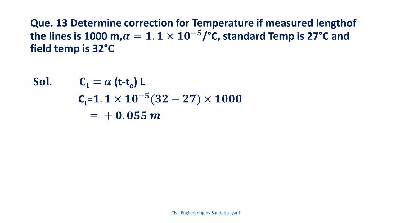
Que. 13 Determine correction for Temperature if measured lengthofthe lines is 1000 m,𝜶 = 𝟏. 𝟏 × 𝟏𝟎−𝟓/°C, standard Temp is 27°C and field temp is 32°C
𝐒𝐨𝐥. 𝐂𝐭 = 𝜶 (t-to) L
Ct=𝟏. 𝟏 × 𝟏𝟎−𝟓(𝟑𝟐 − 𝟐𝟕) × 𝟏𝟎𝟎𝟎
= + 𝟎. 𝟎𝟓𝟓𝒎
Civil Engineering by Sandeep Jyani

Que. 14 Determine sag correction for a 30 m steel Tape under a pull of 80 N. in 3 bays of 10 m each, cross-sectional Area of the Tape is 8 mm² and unit wt of the steel may be taken as 77 KN/m³
Sol. 𝑪𝒔 =−𝑾²𝒍
𝟐𝟒 𝒏𝟐𝒑²
𝑊 = 𝛾𝐴𝐿
= 77 ×10³
109× 8 × 30 × 103
= 18.48 𝑁
𝐶𝑠 =−18.48²×30
24×3²×80²
= −7.411 × 10⁻³𝑚.
Civil Engineering by Sandeep Jyani
Compass Surveying
It is branch of surveying in which direction of Survey lines are measured with a compass and length is determined with chain or tape
6Civil Engineering by Sandeep Jyani

• It is branch of surveying in which direction of survey lines are measured with a compass, and length is determined with chain or tape.
• Generally, compass is used to set traverse in the field
• Traverse is a framework consisting of series of straight lines connected together forming a closed or open polygon
7
Compass Surveying
Points such as A, B, C,D are called traverse points
and the line joining there points are called “Traverse
line.”
A B
D C
Civil Engineering by Sandeep Jyani
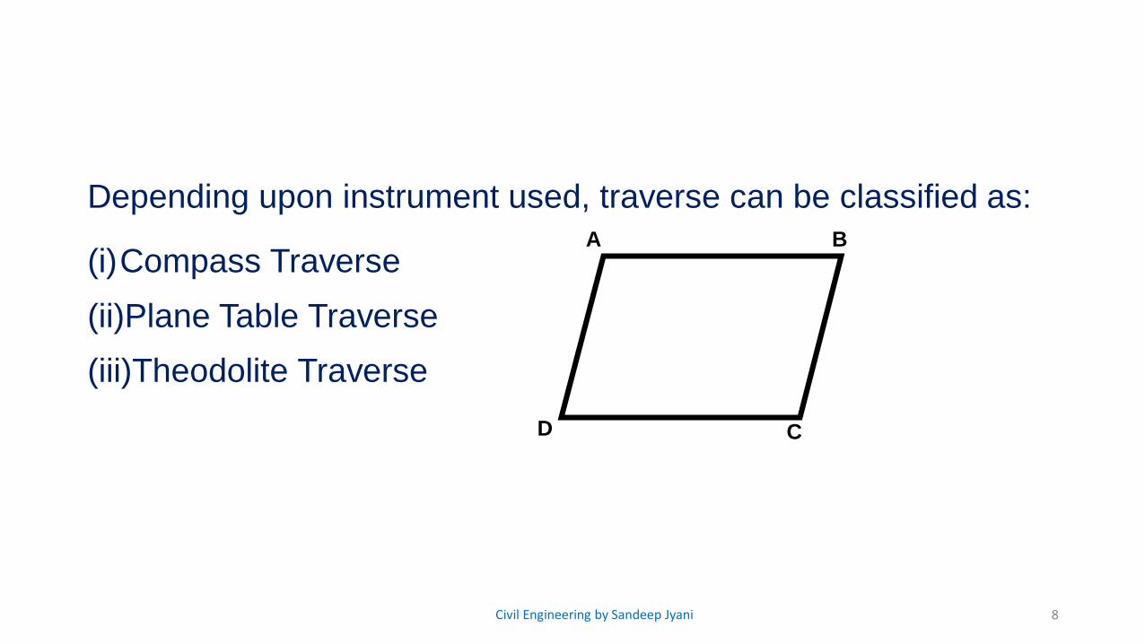
Depending upon instrument used, traverse can be classified as:
(i)Compass Traverse
(ii)Plane Table Traverse
(iii)Theodolite Traverse
8
A B
D C
Civil Engineering by Sandeep Jyani

Difference between chain survey and Traverse Survey
Chain survey
• Only linear measurements are done
• framework consists of network of triangles
• Check line or prop line are required to check accuracy of plot
• Accuracy desired is low as it is used for small area
Traverse survey
• Linear and angular measurements are done
• Frame work consists of open or closed traverse of polygons
• Check lines & proof lines are not required as accuracy is checked by method of Adjustment
• Used for large area when accuracy desired is high.
9Civil Engineering by Sandeep Jyani

Types of Traverse
1. Closed Traverse• It is a traverse that starts from
point of known location and closes at either same point or another point of known location.
10
* both are closed traverse
Loop traverse
Link traverse
2. Open Traverse• It is a traverse which starts
from a point of known location but closes at another point of unknown location.
• An open traverse can be checked by method of chords or astronomical observations.
unknown location
Civil Engineering by Sandeep Jyani
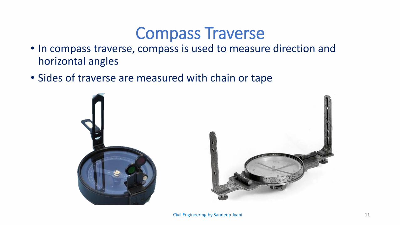
Compass Traverse • In compass traverse, compass is used to measure direction and
horizontal angles
• Sides of traverse are measured with chain or tape
11Civil Engineering by Sandeep Jyani
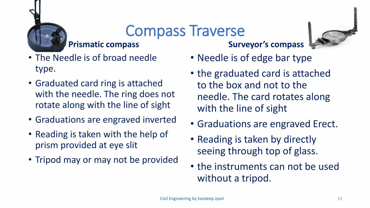
Compass Traverse Prismatic compass
• The Needle is of broad needle type.
• Graduated card ring is attached with the needle. The ring does not rotate along with the line of sight
• Graduations are engraved inverted
• Reading is taken with the help of prism provided at eye slit
• Tripod may or may not be provided
Surveyor’s compass
• Needle is of edge bar type
• the graduated card is attached to the box and not to the needle. The card rotates along with the line of sight
• Graduations are engraved Erect.
• Reading is taken by directly seeing through top of glass.
• the instruments can not be used without a tripod.
12Civil Engineering by Sandeep Jyani

Compass Traverse Prismatic compass
• The graduations are in W.C B system having 0° at south end, 90° at west 180° at North and 270° at East
Surveyor’s compass
• The graduation are in QB system having 0° at North and south, 90° at East & West. East & West are interchanged.
130° S
W 90°
N 180°
E 270°
0° N
E 90°
0° S
W 90°
Civil Engineering by Sandeep Jyani
MEASUREMENT OF ANGLES
• Direction of survey lines can be defined in two ways :• Relative to each other
• Relative to some fixed reference direction
• In surveying, this fixed reference direction is called as “Meridian”
14Civil Engineering by Sandeep Jyani

TYPES OF MERIDIAN
1. True meridian: • True meridian at a point on the Earth surface is the line
joining geographic North and geographic south at that point.
• True meridian at a place is determined with the help of astronomical observation of sum and stars.
• True meridian at a place does not change with passage of time.
2. Magnetic Meridian• Magnetic meridian at a point is the direction indicated by a
freely suspended magnetic bar or needle provided that it should not be affected by magnetic forces other than that of Earth.
• Magnetic meridian at a point changes with passage of time.
15
M.N.
M.S.
T.N.
T.S.
N
S
Civil Engineering by Sandeep Jyani
TYPES OF MERIDIAN
3. Grid Meridian :• For survey of a country, they meridian passing through
central place is taken as reference meridian for whole country and such a reference meridian is called as Grid meridian.
• Example: 82.5° E (Allahabad)
4. Arbitrary Meridian :• It is meridian which is taken in any arbitrary direction
• Generally it is taken in the direction from a traverse station to a well define point such as top of four, chimney, etc.
• Sometimes direction of first traverse line is also taken as reference meridian.
16Civil Engineering by Sandeep Jyani

TYPES OF BEARINGS
• Bearing is the horizontal angle between fixed reference direction and survey line.
• Types of Bearing:• True Bearing
• Magnetic Bearing
• Grid Bearing
• Arbitrary bearing
NOTE : For all important surveys true bearing is preferred over magnetic bearing
17Civil Engineering by Sandeep Jyani
DESIGNATIONS OF BEARING1. Whole circle Bearing : (WCB) / Azimuthal system
• WCB of a line is the horizontal angle between the survey line and North End of reference meridian in clockwise direction
• Prismatic compass is used.
• It ranges from 0° to 360°
18Civil Engineering by Sandeep Jyani

DESIGNATIONS OF BEARING2. Quadrantal Bearing system (Reduced Bearing)
• Quadrantal Bearing is the acute Horizontal angle between reference meridian (N or S) and survey line.
• Surveyors compass is used.
19Civil Engineering by Sandeep Jyani

FORE BEARING AND BACK BEARING• Fore Bearing :
• Fore Bearing of a line is Horizontal angle in the direction of progress of survey.
• Back Bearing:• Back Bearing of a line is the horizontal angle in
the direction opposite of the progress of survey.
𝑩𝑩 = 𝑭𝑩± 𝟏𝟖𝟎°
Positive → FB → less than 180°
Negative → FB →greater than 180°
20Civil Engineering by Sandeep Jyani

FORE BEARING AND BACK BEARING
Note : If Fore Bearing of line is given in quadrantalbearing system, then Back Bearing can be obtained by replacing
• N → S
• S → N
• E → W
• W → E
21Civil Engineering by Sandeep Jyani
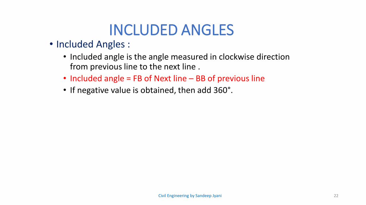
INCLUDED ANGLES• Included Angles :
• Included angle is the angle measured in clockwise direction from previous line to the next line .
• Included angle = FB of Next line – BB of previous line
• If negative value is obtained, then add 360°.
22Civil Engineering by Sandeep Jyani
Que. The WCB of line AB and BC are 30° 15’ and 120°30’, determine included angle B.
23
HOME WORK
Civil Engineering by Sandeep Jyani

HOME WORK. Determine the value of included angle in the closed traverse
24
LINE FB
AB 40
BC 70
CD 210
DA 280
Civil Engineering by Sandeep Jyani

MAGNETIC FIELD OF EARTH
• MAGNETIC FIELD OF EARTH• Earth acts as a powerful magnet with its magnetic lines of
forces running from South end to North end.• Magnetic lines of forces are perpendicular at poles and
parallel at equator• Magnetic needle when freely suspended about its CG, it is
influenced by Earth’s magnetic field and aligns itself parallel to magnetic force of Earth at that point.
• The vertical angle between magnetic needle and Earth surface is called as Angle of dip–• At poles dip = 90°• At Equator dip = 0°
25Civil Engineering by Sandeep Jyani

MAGNETIC DECLINATION
• Generally, magnetic meridian and true meridian do not coincide with each other.
• Horizontal angle between the true Meridian and Magnetic Meridian at the time of observation is called as “magnetic declination” or simply declination.
26
M.N.T.N.
M.N.T.N.
𝜹
𝜹
𝑬𝑨𝑺𝑻𝑾𝑨𝑹𝑫 𝜹+ve
𝑾𝑬𝑺𝑻𝑾𝑨𝑹𝑫 𝜹-ve
Civil Engineering by Sandeep Jyani

MAGNETIC DECLINATION
Note: Magnetic Declination in the field can be measured by determining magnetic Bearing and True Bearing of the same line
• Declination of a time changes from time to time.• Declination at a time changes from point to point.• Variation of declination is shown by isogonic lines.
• ISOGONIC LINES – line passing through points on the surface of the earth at which declination is same at a given point of time.
• A-GONIC LINES – these are special isogonic lines, which pass through points of 0 declination, also at all points on A-Gonic line, magnetic meridian will coincide with true meridian.
27Civil Engineering by Sandeep Jyani
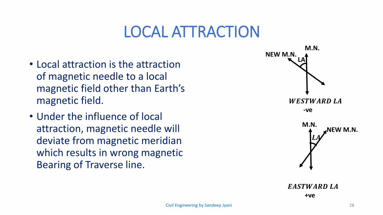
LOCAL ATTRACTION
• Local attraction is the attraction of magnetic needle to a local magnetic field other than Earth’s magnetic field.
• Under the influence of local attraction, magnetic needle will deviate from magnetic meridian which results in wrong magnetic Bearing of Traverse line.
28
NEW M.N.M.N.
NEW M.N.M.N.
LA
𝑳𝑨
𝑬𝑨𝑺𝑻𝑾𝑨𝑹𝑫 𝑳𝑨+ve
𝑾𝑬𝑺𝑻𝑾𝑨𝑹𝑫 𝑳𝑨-ve
Civil Engineering by Sandeep Jyani

LOCAL ATTRACTION
• To determine local attraction, it is mandatory to take fore Bearing and Back bearing of Each traverse line
• It difference between FB and BB is next equal to 180°, then local attraction can be at• Either of the station (station A or B)
• Both the station (station A & B)
29Civil Engineering by Sandeep Jyani

30
THANK YOU