is 10044 (1981): guide for treatment and disposal of ... · treatment of effluents of oil...
TRANSCRIPT

Disclosure to Promote the Right To Information
Whereas the Parliament of India has set out to provide a practical regime of right to information for citizens to secure access to information under the control of public authorities, in order to promote transparency and accountability in the working of every public authority, and whereas the attached publication of the Bureau of Indian Standards is of particular interest to the public, particularly disadvantaged communities and those engaged in the pursuit of education and knowledge, the attached public safety standard is made available to promote the timely dissemination of this information in an accurate manner to the public.
इंटरनेट मानक
“!ान $ एक न' भारत का +नम-ण”Satyanarayan Gangaram Pitroda
“Invent a New India Using Knowledge”
“प0रा1 को छोड न' 5 तरफ”Jawaharlal Nehru
“Step Out From the Old to the New”
“जान1 का अ+धकार, जी1 का अ+धकार”Mazdoor Kisan Shakti Sangathan
“The Right to Information, The Right to Live”
“!ान एक ऐसा खजाना > जो कभी च0राया नहB जा सकता है”Bhartṛhari—Nītiśatakam
“Knowledge is such a treasure which cannot be stolen”
“Invent a New India Using Knowledge”
है”ह”ह
IS 10044 (1981): Guide for Treatment and Disposal ofEffluents of Petroleum Refining Industry [CHD 32:Environmental Protection and Waste Management]


IS : 10044-1981
. . \ ,
I
Indian Standard GUIDE FOR TREATMENT AND DISPOSAL OF
EFFLUENTS OF PETROLEUM REFINTNG INDUSTRY
(First Reprint JUNE 1992)
UDC 628.543 ( 026 ) : 665.66
0 Copyright 1982
BUREAU OF INDIAN STANDARDS MANAK BHAVAN, 9 BAHADUR SHAH ZAFAR MARG
NEW DELHI 110002
Gr 7 December 19 82
Indian Standard GUIDE FOR TREATMENT AND DISPOSAL OF
EFFLUENTS OF PETROLEUM REFINING INDUSTRY
Water Sectional Committee, CDC 26
Chahnan DR NILAY CHAUDHURI
Members MEMBER-SECRETARY ( AIternaie to
Dr Nilay Chaudhuri ) SHRI J. S. CHAUDHRI
SHRI H. G. GARB ( Alternote ) CHWP WATER ANALYST, KING INSTI-
TUTE, MADRAS SHRI J. D’CRUZ
Srrar K. R. SAHU ( Alternate ) DEPUTY DIRECTOR ( CHEM ). RDSO,
Represeniing Central Board for the Prevention 8c Control of
Water Pollution, New Delhi
Haryana State Board for the Prevention & Control of Water Pollution, Chandigarh
Director of Public Health. Govt of Tamil Nadu, Madras
Delhi Water Supply & Sewage Disposal Under- taking, New Delhi
Railway Board, Ministry of Railways LUCKNOW
CHEMIST & M~TALLURGJST, W. RLY, BOMBAY ( Alfernafe )
SHRI M. V. DESAI Indi~aalcu~ernical Manufacturer’s Association,
SHRI MANGAL SINGH ( Alternate ) SHRI 0. L. DUGGAL Ballarpur Industries Ltd, Balhupur
SHIU R. VARADHAN ( Alternate ) SHRI B. K. DUTTA Ion Exchange ( India ) Ltd, Bombay
SHRI N. RAMACHANDRAN ( Alfernate ) SHRI R. C. DWIVEDI U. P. Water Pollution Prevention & Control
Board, Lucknow SHRI S. P. SAXENA ( Afternate )
( Continued on page 2 )
@ Copyrighf 1982 BUREAU OF INDIAN STANDARDS
This publication is protected under the Zndiun Copyright Act ( XIV of 1957 ) and reproduction in whole or in pal’t by any means except with written permission of the publisher shall be deemed to be an infringement of ,copyright under the said act.

IS : 10044 - 1981
( Continued from page 1 )
Members SHRI R. S. EKBOTE DR M. I. GCIRBAXANI SHRI S. HANMANTH RAO
Representing Hindustan Organic Chemicals Ltd. Rasayani The Tata Iron & Steel Co Ltd, Jamshedpur Karnataka State Board for Prevention & Control
of Water Pollution, Bangalore SHRI C. H. GOVINDA RAO ( Alternate 1
SHRI C. P. JAIN SHRI J. JHA ( Ahernale )
SHRI K. K. KAMATH
Central Electricity Authority, New Delhi
SHRI J. D. JOYSINGH ( Alternate ) DR P. K. MATHUR PROP R. S. MEHTA
SHRI M. D. DAVJZ ( Alternate ) MEMBER-SECRETARY
SHRI S. K. MITRA
SHRI S. D. MUNDHRA SHRI U. C. MANKAD ( Alternate )
SHRI D. V. S. MURTHY
Kerala State Board for Prevention & Control of Water Pollution, Trivandrum
Bhabha Atomic Research Centre,~o;trl$y Gujarat Water Pollution Board,
Gandhinagar
Maharastra Prevention of Water Pollution Board, Bombay
West Bengal Prevention & Control of Water Pollution Board, Calcutta
Geo-Miller & Co Pvt Ltd. Calcutta
M. P. State Prevention & Control of Water Pollution Board, Bhopal
SHRI P. K. BANERJEE ( Alternate ) SHRI R. NATARAJAN Bharat Heavy Electricals Ltd, Hyderabad
SHRI G. KRISHNAYYA ( Alternate I ) DR A. PRABHAKAR RAO ( Alternate II )
SHRI S. K. NEOGI Institution of Public Health Engineers, India. Calcutta
DIL M. BANERJEE ( Alternate ) DR V. PACHAIYAPPAN The Fertiliser Association of India, New Delhi SHR~ R. PARAMASIVAM National Environmenral Engineering Research
Institute ( CSIR ), Nagpur SHRI M. V. NANOTI ( Alternate )
SHRI A. K. PODDAR Steel Authority of India Ltd, New Delhi SHRI A. K. DAS ( AIfernate )
SHRI H. S. P~RI Punjab State Board for the Prevention & Control of Water Pollution, Patiala
SI~RI Q~MAT RAI ( Alternate ) SHRI B. B. RAO Ministry of Work & Housing
DR I. RADHAKRISHNAN ( Alternate ) SHRI G. S. RAY The Fertilizer ( Planning & Development ) India
Ltd, Sindri DR S. K. ROY The Alkali & Chemical Corporation of India Ltd.
Calcutta SHRI P. K. CHAKRAVARTY( Alternate )
SHRI K. R~IDRAPPA Engineers India Ltd, New Delhi SHRI S. N. CHAKRABARTI ( Alternate )
SHRI A. K. SAHA Natiodl Test House, Calcutta SHRI P. BHA~ACHARYYA ( Alternate )
SHRI R. M. SHAH Tata Chemicals Ltd, Bombay SHIU R. K. GANDHI ( Alternate)
( Continued on page 19 )
2

IS:10044 -1981
Indian Standard
GUIDE FOR TREATMENT AND DISPOSAL OF EFFLUENTS OF PETROLEUM
REFINING INDUSTRY
0. FOREWORD
0.1 This Indian Standard was adopted by the Indian Standards Institution on 19 November 1981, after the draft finalized by the Water Sectional Committee had been approved by the Chemical Division Council.
0.2 There are a number of oil refineries in India engaged in crude refining, both imported and indigenous. Large quantities of water are used in refining processes in this industry; these may be for cooling purpose, power plant or refining processes. The effluents from the refineries pose pollution problems if discharged untreated.
0.3 A waste treatment system is an essential part of every petroleum refinery installation. This should be considered during the development, selection and design stages of new refineries or of any major modifications of existing facilities in refineries. Further, importance should be given for recycling wastes after treatment within the refinery itself. Its waste control facilities should also be reshaped to meet the needs of process modernization and changing demands on water resources. Consequently, a waste control system is not a s,tatic thing and its day-to-day operation should not be expected to remain constant. The design of a waste treatment system should be one which is adaptable to needs that vary with production rates and to overloads that result from emergency conditions.
0.4 The object of this guide is to provide basic information on methods of treatment of effluents of oil refineries and to make definite recommendations for treatment of these effluents in India. This guide does not seek to provide detailed information on the designing or operation of an effluent treatment plant. Further, the methods recommended have been selected taking into consideration the practicability of their adoption by the industry. As and when more information and data are available, this guide will be revised.
0.5 Since the water consumption and effluent volume per unit of oil refined vary from one refinery to another, no cost figure of a treatment unit has
3

IS : 10044 - 1981
been included in this guide. Refineries in India with once-through cooling system use water between 18 000 and 27 500 m8 per 1 000 tonnes of crude processed resulting in waste water generation of almost the same range in contrast to those having cooling water recirculation system utilizing water between 1 350 and 5 650 ma per 1 000 tonnes of crude processed and gene- rating waste water between 320 and 1 800 nr9 per 1 000 tonnes of crude processed.
Q.6 The extent of pollution of inland surface waters and marine coastal areas permitted by discharge of effluents is laid down in IS : 2296-I982* and IS : 7967-1976t respectively. IS : 2490 ( Part I )- 198 1 $ laysdown the tolerance limits for industrial effluents.
0.7 Methods of sampling and test for industrial effluents are covered in IS : 2488 ( Part I )-19668, IS : 2488 ( Part II )-1968§, IS : 2488 ( Part III )- 19685, IS : 2488 ( Part IV )-1974s and IS : 2488 ( Part V)-19769.
l. SCOPE
1.1 This standard covers the methods of treatment and disposal of effluents of petroleum refineries.
2. SOURCES AND CHARACTERISTICS OFEFFLUENTS
2.1 sources
2.1.0 The major water pollutant in refinery operations is oil, besides chemicals that may be formed during treatment of petroleum products by chemical processes for removal of undesirable constituents.
2.1.1
a)
b)
a
The effluents may be classified under the following five categories:
Effluent free from oil and dissolved organic material; c Effluent accidentally contaminated with oil;
Effluent continuously contaminated with oil but not contaminated with other soluble organic material;
*Tolerance limits for inland surface waters subject to pollution ( second revision ). tCriteria for controlling pollution of marine coastal areas. STolerancc limits for industrial etlhents: Part I General limits ( second revision ). gMethods of sampling and test for industrial efliucnts ( Parts I to V ).
4

IS:10044-1981
d) Process effluent; and e) Sanitary and domestic effluent.
2.1.1.1 Efiuert@ free from oil and dissolved organic material - These originate from:
a) Boiler blow-down, b) Water treatment plant effluent, and c) Storm water from oil-free areas.
2.1.1.2 &‘fluents accidentally contaminated with oil - These originate from:
a) Storm water from tank farms; and b) Blow-down from circulating cooling water system.
2.1.1.3 &$?uents continuously contaminated with oil but free from soluble organic material - These originate from:
a) Storm water from oil processing areas, and
b) Ballast water.
2.1.1.4 Process e&e&s - These originate from:
a) Desalter,
b) Condensate from steam stripping operations,
c) Pump gland cooling water,
d) Barometric condenser water containing emulsions, and
e) Wash water from treating plants.
2.1.1.5 Sanitary and domestic efluents - These originate from:
a) Toilets, and
b) Canteen.
2.2 Characteristics - General characteristics of the composite oil refinery waste water ( before treatment ) are likely to be as given in Table 1 ( see aiso 3.1).
3. EFFECTS OF POLLUTION
3.1 ‘The principal public health hazard caused by untreated refinery effluents is pollution of water courses and land with toxic chemical compounds such as oil, hydrogen sulphide, ammonia, mercaptans, phenol, cyanides, fluorides, acids, alkalis, chromates, and traces of heavy metals.
5

IS : 10044 - 1981
TABLE 1 GENERAL CHARACTERISTICS OF COMPOSITE OIL REFINERY WASTE WATER
( Clause 2.2 )
2. CHARACTERISTIC RANGE OF VALUE
(1) (2) (3)
i) ii)
iii)
iv)
v)
vi)
vii)
viii)
Fr:e oil, mg/l
F mulsified oil, mg/l
Sulphides ( as H2S ) and mercaptans, mg/l
Phenolic cc 7pounds ( as CBH,OH ), mg/l
Biochemical oxygen demand ( 5 days at 20°C ), mg/l
Suspended solids, mgll
Chromate ( as CrO, ) and zinc ( as Zn ) or phosphate ( as PO, ) from cooling water, mg/l
pH value
2000t03000
80 to 120
10 to 220
12 to 30
100 to 300
200 to 400
5 to 20
6.5 to 9.0
NOTE -- Cyanides and ammonia may be present in the waste water from refineries where cracking process is practised.
3.1.1 Acids and alkalis are toxic to aquatic life and inhibit self-purification of water courses. Fluorides cause dental fluorisis and dental caries which affect teeth, joints and bones. Presence of hydrogen sulphide, mercaptans and phenol produce disagreeable odour in water and, at the same time, increases biochemical oxygen demand of water. Oils, which are difficult to biodegrade, form a thin film over water surface, causing unsightly appear- ance and interfere with the natural process of aeration and photosynthesis, and also cause fire hazards.
4. TREATMENT
rl.llOil-free waste waters should never contain oil and, hence, they may bypass waste treatment facilities and discharge directly into the refinery outfall line after decontamination through gravity separators or surge ponds to take care of for accidental contamination ( see 2.1.1.2), ( facilities should be provided for oil removal ).
4.2 The general treatment methods to handle waste waters from refinery operations are as follows.
4.2.1 Primary Treatment - It consists of free oil removal. Oil removal is also affected by in-plant processes like stripping and extraction. Further, removal of oil from the waste water is carried out principally in two
6

stages - the fist stage featuring gravity separation and t>e second stage floatation with or without addition of chemicals/coagulants ( see 4.2.2 ). Gravity separation is meant for removal of separable free oil.
Is: loo44 - 1981
4.2.1.1 Oily effluents originating from various sources in the refinery are collected in a sump and routed to an oil separator for removal of free oil. Oil separators are designed considering hydraulic load, density and viscosity of the oil and diameter of oil globules. A brief description of a typical API oil separator ( see Fig. 1 ) is given below.
The API separator mainly consists of an inlet bay, a middle or a separator bay and an outlet bay. The inlet bay contains sluice gates for commissioning or decommissioning the individual bays of the separator. It contains a vertical hanging baffle to retain the oil and also arrangement to collect the separated oil.
The middle or separator bay is the place where remaining portion of the oil is separated by reducing the velocity, so that the water becomes almost quiescent. The separated oil is retained in the middle bay by another vertical hanging baffle situated at the end of this bay and the collected oil is skimmed by a skimmer provided near this baffle. A flight scraper provided in the middle bay brings oil to the skimmer for its removal and also at 1?:e same time pushes the sludge collected at the bottom to the sludge pit or hopper for periodic removal.
The outlet bay contains a weir over which the oil-free water flows out for further treatment. Oil content in the effluent after the API separator is normally less than 100 mg/l in water.
4.2.1.2 It is very important that the oily effluent be sent to a primary oil removal basin and to the API or gravity separators by means of gravity flow. Pumps, especially centrifugal type, should be avoided to minimize formation of oil emulsion with water which would call for additional chemical method for its removal. Where pumping of oily effluent is essen- tial after the primary oil removal basin, screw type or diaphragm type pumps should be used.
4.2.1.3 Stripping - Stripping is another physical method. It is done with the aid of steam to remove gases like hydrogen sulphide, mercaptans and ammonia and to some extent phenol and free cyanides.
4.2.1.4 Extraction - Extraction is yet another physical method which is used to remove phenolic compounds in refinery operations. In this process, solvents like tricresyl phosphates and mixed organic esters are used for extraction of phenol from,wastes. Use of petroleum fractions or crude oil is also made for extraction in some of the refineries.
7

IS:lOM4- 1981
43.2 Secondary Treatment Methods - The secondary treatment methods may be classtied as follows:
a) Chemical method, and
b) Biological method.
4.2.2.1 Chemical method - The main purpose of a chemical method is to remove emulsified oil with addition of flocculating agents and also to remove suspended solids and toxic substances, thereby conditioning the effluents for further treatment by biological method. Sedimentation is normally employed to remove suspended solids after chemical treatment. Various chemical methods available may be further classified under the following four categories:
a) Neutralization method,
b) Precipitation and clarification method,
c) Chemical oxidation method, and
d) Regeneration method.
a) Neutralization - Neutralization methods are applied to many types of refinery wastes as primary treatment. The wastes considered here are:
1) Dilute acid or alkaline wastes from various re$ning processes and from water treatment plant - Neutralized to produce a neutral effluent.
2) Spent caustic solution - Neutralized with either spent acid or ‘acidic stack gases.
3) Sulphuric acid sludges - Neutralized with alkaline wastes.
4) Spent catalyst - Neutralized with spent caustic wastes.
5) Hydrojluoric acid wastes - Neutralized with caustic soda solution.
b) Precipitation and ctariJication method - Precipitation method is used in the treatment of several types of refinery wastes such as:
1) Spent caustic solutions - Acidic oils in caustic are precipitated by neutralization.
2) SuZphide water - Precipitated with iron salts.
3) Solutions of sulphonates - Precipitated by the addition of lime.
8

I
TRASH RACK\
DESIGNED FOR INSERTING RUBBER BALLOON STOPPERS FOR DIVERTING FLOWS FOR CLEANING SEPARATOR SECTION SLUICE GATES OR GATE VALVES MAY BE INSTALLED IF DESIRED
SLUDGE PUMP SKIMMEO
- -_-- ++
I I I
OIL SKIMMER ._I LFLIGHT SCRAPER CHAIN SPROCKET
OOD FLIGHT OIL - RETE,NTION
DIFFUSION DEVICE (VERTICAL BAFFLE) ok SKIMMER
FLOW -
7 ~~ SLUDGE HOPPERS SECTlOrd A A FIG. 1 API OIL-WATER SEPARATOR
9

As in the Original Standard, this Page is Intentionally Left Blank
IS:10044-1981
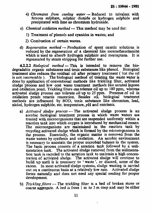
4) Chromates from cooling water - Reduced to trivalent with ferrous sulphate, sulphur dioxide or hydrogen sulphide and precipitated with lime as chromium hydroxide.
c) Chemical oxidation method - This method may be used for:
1) Treatment of phenols and cyanides in wastes; and
2) Combustion of certain wastes.
d) Regeneration method - Production of spent caustic solutions is reduced by the regeneration of a chemical like monoethanolamine which is used to absorb hydrogen sulphide and mercaptans. It is’ regenerated by steam stripping for further use.
4.2.2.2 Biological method - This is intended to remove the bio- degradable organic substances and toxic substances like phenol. Biological treatment also reduces the residual oil after primary treatment ( but the oil is not recoverable ). The biological method of treating the ‘waste water is done by application of conventional methods like trickling filter, activated sludge ‘process and low cost waste treatment methods Iike aerated lagoon and oxidation pond. Trickling filters can tolerate oil up to 100 ppm, whereas activated sludge process can tolerate oil up to 25 ppm. Presence of oil in oxidation ponds retards reaeration. Besides oil, biological treatment methods are influenced by BOD, toxic substance like chromium, lead, nickel, hydrogen sulphide, etc, temperature, pH and nutrients.
a) Activated sludge process - The activated sludge process is an aerobic biological treatment process in which waste waters are treated with microorganisms that are suspended uniformIy within a reaction tank into which oxygen is introduced by mechanical means. The microorganisms are maintained in the reaction tank by recycling activated sludge which is formed by the microorganisms in the process. Essentially, the organic matter is removed from the waste waters by synthesis and oxidation. An aerobic environment is necessary to maintain the proper microbial balance in the system. The basic process consists of a aeration tank followed by a sedi- mentation tank. The activated sludge removed from the sedimenta- tion tank is recycled to the aeration tank to maintain a high concen- tration of activated sludge. The activated sludge will continue to build up until it is necessary to ‘ waste ‘, or discard, some of the excess. In most activated*sludge systems, sludge wasting is carried out on a continuous basis at a relatively low rate. Activated sludge forms naturally and does not need any special seeding for proper development.
b) Trickling filters - The trickling filter is a bed of broken stone or coarse aggregate. A bed is from 1 m to 3 m deep and may be either
11
IS : loo44 - 1981
rectangular or circular. It may be deeper when plastic packing is used. Fixed or moving sprinklers distribute the waste water over the surface of the bed. A gelatinous film of slime composed of aerobic organisms develops on the surface of the aggregate. As the waste water trickles over the Glm, both dissolved and suspended organic matter are removed by adsorption. The adsorbed matter is oxidized by the organisms in the slime during their metabolic processes. Air flows through the filter by convection, thereby provid- ing the oxygen needed to maintain aerobic conditions. The oxidized waste water from the filter is clarified in a sedimentation tank before discharge into a watercourse. The microbial film that develops on the surface of the rocks is responsible for removing the organic materials from solution.
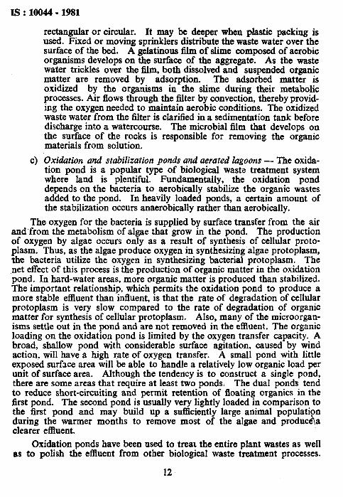
c) Oxidation and stabilization ponds and aerated lagoons - The oxida- tion pond is a popular type of biological waste treatment system where land is plentiful. Fundamentally, the oxidation pond depends on the bacteria to aerobically stabilize the organic wastes added to the pond. In heavily loaded ponds, a certain amount of the stabilization occurs anaerobically rather than aerobically.
The oxygen for the bacteria is supplied by surface transfer from the air and’from the metabolism of algae that grow in the pond. The production of oxygen by algae occurs only as a result of synthesis of cellular proto- plasm. Thus, as the algae produce oxygen in synthesizing algae protoplasm, the bacteria utilize the oxygen in synthesizing bacterial protoplasm. The net effect of this process is the production of organic matter in the oxidation pond. In hard-water areas, more organic matter is produced than stabilized. The important relationship, which permits the oxidation pond to produce a more stable effluent than influent, is that the rate of degradation of cellular protoplasm is very slow compared to the rate of degradation of organic matter for synthesis of cellular protoplasm. Also, many of the microorgan- isms settle out in the pond and are not removed in the effluent. The organic loading on the oxidation pond is limited by the oxygen transfer capacity. A broad, shallow pond with considerable surface agitation, caused by wind action. will have a high rate of oxygen transfer. A small pond with little exposed surface area will be able to handle a relatively low organic load per unit of surface area. Although the tendency is to construct a single pond. there are some areas that require at least two ponds. The dual ponds tend to reduce short-circuiting and permit retention of floating organics in the first pond. The second pond is usually very lightly loaded in comparison to the first pond and may build up a sufficiently large animal population during the warmer months to remove most of the algae and producha clearer effluent.
Oxidation ponds have been used to treat the entire plant wastes as well as to polish the effluent from other biological waste treatment processes.
12

IS : 10044 - 1981
/Although oxidation ponds have been constructed for refinery wastes, very few data are available on their operation. Retention periods in oxidation ponds range from a little more than 1 day up to 90 days. For the most part, the reduction in organic matter is a function of the retention period and effluent concentration. Generally, the entire plant wastes are treated in the oxidation ponds, so that the organic concentration applied is quite iow. The net result is a low rate of microbial metabolism, and a long period of retention is required for organic reduction. As a rule, simple oxidation ponds are ineffective if the holding time is less than 7 days.
Oxidation ponds for refinery may employ surface aeration units in the first stage to permit loadings at 10 times the conventional oxidation pond loadings. Conventional lagoons may be used as a second-stage treatment for producing a high quality effluent. This system has been termed the ‘ aerated lagoon ’ system. One of the major problems with oxidation ponds is emulsions which block sunlight penetration and prevent algae growth. Normal oxidation pond operation is retarded until the emulsion is broken by bacterial metabolism. The low rate of bacterial metabolism in the absence of oxygen requires a large pond volume to break the emulsion.
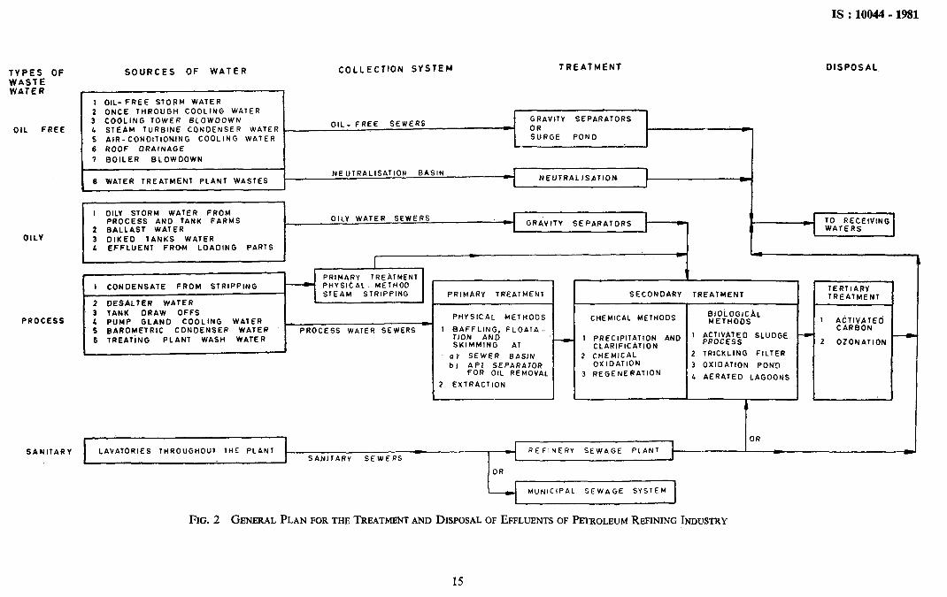
4.2.3 Tertiary Treatment Method - Tertiary treatment has been limited to activated carbon filtration process and ozonation which are effective in removal of the taste and odour and organics from biologically treated waste waters. However, these methods are extremely costly. Many of the refineries prefer to use oxidation ponds after biological treatment to serve as tertiary treatment. This is one of the cheapest methods of treatment where enough land is available. A general plan for the sources, the collection, the treatment and the disposal of refinery liquid wastes is shown in Fig. 2.
4.2.4 The treated liquid wastes which satisfy the relevant tolerance limits are finally disposed by controlled dilution into the neighbouring stream, river or sea.
5. POLLUTION CONTROL PRACTICES
5.1 In waste control, preventive methods other than treatment should be used for reducing the amount of polluting wastes. New techniques should be tried with the aim of lowering treatment costs. The preventive measures can be studied under the following headings:
5.1.1 Pollution Control Measures - These may include:
a) Provision of separate drainage and sewer systems to prevent pollu- tion of large volumes of clean water by small volumes of dirty water;
13

IS : 10044- 1981
b) Segregation of waste water streams may be done, so that non-oily chemical wastes and oily process wastes are collected and treated separately;
c) Following water conservation measures at refinery will reduce both water supply and cost of waste treatment:
Installation of air cooled exchangers and cooling towers; pump gland cooling water to serve as cooling tower blow-down and use of oily water emulsion from barometric condenser; and stripped sour water and phenolic waste water as make-up water for desalter.
5.1.2 Process Design ModiJications - These may include:
a) Acid sludge or spent clay disposal problems may be eliminated by replacing acid treatment or clay treatment of lubricating oil with propane deasphalting or with hydrofinishing process.
b) Substitution of continuous process for batch processes.
c) Use of processes which include regeneration of chemicals used for hydrogen sulphide and mercaptan removal may avoid problems associated with disposal of caustic wastes.
d) Use of downgraded chemicals is economical for both process and waste control. Fresh caustic used ,for washing light hydrocarbon streams is used for gasoline treating.
e) Use of methods for conversion of hydrogen sulphide to elemental sulphur.
5.13 Local Pretreatment or Disposal
5.1.3.1 In general, it is advantageous to treat or dispose of concentrated and unusual wastes locally. Treatment of highly polluted waste streams at the sources can prevent gross pollution of large volumes of relatively dean waste water. Such treatment is a more economical solution to the problem than discharging directly into the refinery sewers. For example:
a) Stripping ammonia and hydrogen sulphide condensate before discharging into sewer.
b) Neutralizing the spent caustic waste before discharging into sewer.
5.1.4 Operation Control Measures
5.1.4.1 Operating procedure has a significant effect on waste control. However, control practices should have the interest and support of manage- ment, process supervisors and operators. A waste control group or a qualified supervisor may be appointed who should be responsible for the
14
IS :10044 -1981
Oil. FREE
OILY
PROCESS
SANITARY
SOURCES OF WATER COLLECTION SYSTEM TREATMENT
I 1 I
DISPOSAL
1 OIL-FREE STORM WATER
2 ONCE THROUGhi COOLING WATER
3 COOLING TOWER BLOWOOWN
L STEAM TURBINE CONOEkSER WATER .
5 AIR-CON0lTl0NING COOLING WATER
6 ROOF DRAINAGE
7 BOILER BLOWDOWN
OIL- FREE SEWERS GRAVITY SEPARATORS
_ OR c SURGE POND
6 WATER TREATMENT PLANT WASTES NEUTRALISATION J
-
I OILY STORM WATER FROM PROCESS AND TANK FARMS
2 BALLAST WATER
3 DIKE0 TANKS WATER L EFFLUENT FROM LOAOING PARTS
GRnVlTY SEPARATORS c \: TO RECEIVING
w <
-A
I CONDENSATE FROM STRIPPING
2 OESAlTER WATER
3 TANK ORAW OFFS
4 PUMP GLANO COOLING WATER 5 BAROMETRIC CONDENSER WATER
6 TREATING PLANT WASH WATER
PHYSICAL METHODS
PROCESS WATER SEWERS l BAFFLING, FLOATA.. tlON AND SKIMMING AT
al SEWER BASIN
b) API SEPARATOR FOR OIL REMOVAL
2 EXTRACTION
t
I SECONDARY TREATMENT I
I CHEMICAL METHODS
I 1
1 I PRECIPITATION AND
CLARIFICATION
1 ;;;lC”E”;‘SO SLUDGE
2 CHEMICAL 2 TRICKLING FILTER
OXIDATION 3 OXIDATION PONO 3 REGENERATION
L AERATED LAGOONS
f I 1 I 1 1 OR
TERTIARY TREATMENT
1 :;‘Rl;$;E”
2 OZONATlOh I 1 4
LAVATORIES THROUGHOUT 1HE PLANT REFINERY SEWAGE SAN1 t ARY SEWERS
OR
MUNICIPAL SEWAGE SYSTEM
FIG. 2 GENECRAL PLAN FOB THE TREATMENT AND DISPOSAL OF EFFLUENTS OF PETROLEUM REFINING INDUSTRY
I5

As in the Original Standard, this Page is Intentionally Left Blank

IS : 10044 - 1981
quality of waste water that leaves the refinery. In addition, the following should be practised:
a)
b)
4
4
4
The group or supervisor, with the aid of the refinery laboratory should maintain a complete record of data concerning sources, characteristics and quantities of all wastes and waste water streams. These data should be reported periodically.
Operating departments should be held responsible for their own discharges of waste water. They should advise the control group or supervisor of each special discharge they intend to make, so that precautions can be taken to prevent adverse effects.
Both management and control group should be informed of any process changes or new sewer connections. Current accurate maps and plans of all waste disposal facilities should be maintained.
Close, and cooperative relations between the operating and waste control group personnel are essential for successful waste control.
Waste control group should make all the’ employees conscious of waste problems by continually reminding them of the problems through booklets or leaflets.
5.1.5 Periodic Inspections - Periodic inspection of the waste system is essential as preventing oil and other polluting wastes from getting into plant sewers is preferable to the heavy expenditure of both money and efforts necessary to remove them.
5.1.6 Good House-keeping - Good house-keeping should be emphasized. Apparently, it can be attained by instilling the proper attitude in operating personnel and then it can be maintained by periodic inspection.
6. DESIGN OF COLLECTING SYSTEMS
6.1 Refinery collection or drainage systems should be constructed, so that waters subject to contamination by oil do not drain directly into adjoining properties or into adjacent surface waters. Drainage lines should be laid out so that the oil-contaminated wastes flow.by gravity to the oil-water separators. Pumping of oil-water mixtures tends to form emulsions and should be avoided. If pumping cannot be avoided before separation of at least the bulk of the oil, pumps specially designed to minimize emulsification should be used.
6.2 Accurate maps and plans of the drainage systems, separators, catch basins, and other facilities should be maintained to show all details of the original installation, as well as any changes or additions.
17

IS : 10044 - 1981
6.3 Intakes to storm water sewers should be provided with adequate sediment chambers. As a precautionary measure, separate storm sewers should be provided with water-sealed connections.
6.4 Drainage systems for cooling and process waste waters should be provided with water-sealed intakes at every point where waste waters enter in order to prevent hydrocarbon vapours, present in the sewer system, from escaping into process areas. When process waste water contains quantities of sediment, suitable inlet catch basins should be provided.
6.5 Sewer systems should be provided with manholes and junction boxes to permit ready access. These openings are necessary to permit gaging and cleaning of sludge accumulations to maintain the full capacity of the sewer system. Access points are also needed for sampling and visual observation when the sources of oil or other waste material are to be determined.
6.6 In general, all branch or lateral sewers should be isolated from main sewers by the use of suitable water seals and manholes. This prevents the travel of hydrocarbon vapours from one section of the system to another and confines to a limited area any fire or explosion that might occur. To prevent trapping oil layers, manholes in refinery areas should usually be provided with water-sealed inlets and open outlets. In specific locations where trapped outlets are to be installed, the outlets should be provided with vents to prevent syphoning and vapour locks. Properly designed vents should be provided to vent hydrocarbons safely from manholes of sewer systems handling light hydrocarbons. Failure to do so may create a fire hazard at ground elevation. Vents should be installed at manholes where a pressurized sewer is converted to gravity sewer. Vents should be discharged in areas that are remote from furnaces or other permanent sources of ignition; they should not be located near operating platforms or air intakes, and they should be high enough to disperse vapours safely. Furthermore, vents should be distinctly marked. Indiscriminate venting may create hazards if the design permits air to be sucked into the system, thereby diluting a safety-rich atmosphere to one that is potentially explosive.
6.7 It is clear that the design .considerations for venting and sealing or trapping refinery waste drainage systems differ from engineering practice for sanitary sewage systems. Safety precautions to prevent an explosive condition and/or the spread of fire are paramount design requirements in a refinery drainage system.
18

IS : 10044 - 1981
( Continued from page 2 )
Members Representing SHRI P. R. SETH Excel Industries Ltd, Bombay
SHRI S. P. Iya~ ( Alternate ) SHRI K. SURIYANARAYANAN All India Distillers’ Association, New Delhi
SHRI G. C. GAUTAM ( Alternate ) DR HARI BHAGWAN, Director General, ISI ( Ex-oficcio Member )
Director ( Chem ) Secretar.v
SHRI A. K. BAHL Assistant Director ( Chem ), IS1
Waste Treatment Methods Subcommittee, CDC 26 : 1
Convener
SHR~ A. RAMAN
Members SHRI S. K. BHATTACHARJYA
SHRI N. RAMACHANDRAN ( Afterna DR R. N. CHAKRABARTY SHRI J. S. CHAUDHRT
SHRI H. G. GARG ( AIternute ) CHIEF WATER ANALYST, KINKS INsn-
rum, MADRAS DR D. CHOUDHURY
SHIU V. K. DIKSH~T ( Alternate ) DIRECTOR ( CSMRS )
SHRI N. C. RAWAL ( Alternate ) SHRI R. C. DWIVEDI
National Environmental Engineering Research Institute ( CSIR ), Nagpur
Ion Exchange ( India ) Ltd, Bombay rte ) Universal Enviroscience Pvt Ltd, New Delhi Haryana State Board for the Prevention & Control
of Water Pollution, Chandigarh
Direcz;d;~sPublic Health, Govt of Tamil Nadu,
Indian Chemical Manufacturers’ Asssociadon, Calcutta
Central Water Commission, New Delhi
U. P. Water Pollution, Prevention & Control Board, Lucknow
SHRI S. P. SAX&A ( Alternate ) DR A. K. GUPTA Hindustan Fertilizer Corporation Ltd, DUrgaPUr
SHHI T. P. CHATTERJEE ( AIterrfute ) SHRI S. GUPTA Central Board for the Prevention & Control of
Water Pollution, New Delhi SHRI H. S. MATHARU ( Alternate )
SHR~ JOHN RAJU Steel Authority of India Ltd. New Delhi SHRI A. P. SINHA ( Alfernate )
SHR~ R. V. KADAM SHR~ N. V. VASHI ( Afternote )
SHRI K. R. KRISHNASWAMI SHRI A. K. MAJUMDAR
SHRI U. C. MANKAD ( Alternate ) SHRI S. V. MANI
SHRI S. R. LUTHRA ( Alternate )
Paramount Pollution Control Pvt Ltd Yadodara
Madras Fertilizers Ltd. Madras Gee-Miller & Co Pvt Ltd, Calcutta
Greaves Cotton & Co Ltd, Bombay
( Continued on page 70 )
19

rIs:10044-1981
( Canthued from page 19 )
Members MBMBER~ECRETARY
Representing Maharasbtta Prevention of Water Pollution Board.
BOIIIbaY SHRI V. S. MORE Indian Oil Corporation Ltd ( Refineries & Pi&
lines Division ), New Delhi SHRI PARAMJIT SIN~H ( Alternate )
SHRI D. V. S. M~RTHY ’
DR G. K. KHARE ( AIternote ) SHRI R. NATARAJAN
SHRI B. M. RAHUL ( Alternate ) DR V. PACMIYAPPAN DR R. PITCHAI SHRI H. S. Prtm
SHRI QIMAT RAI ( AItemute ) SHR~ G. S. RAY
SHRl M. K. ROY SHRI J. M. TULI
SHRI K. RUDRAPPA ( Alternate ) SIN T. K. VEDARAMAN
DR S. R. SHUKLA ( Alternate )
-M. P. State Prevention & Control of Water Pollution Board, Bhopal
Hindustan Dorr-Oliver Ltd, Bombay
The Fertiliser Association of India, New Delhi College of Engineering, Madras Punjab State Board for the Prevention & Control
of Water Pollution, Patiala
The Fertilizer (Planning & Development ) India Ltd. Sindri
Chief Inspectorate of Factories, Ranchi Engineers India Ltd, New Delhi
Ministry of Works & Housing
Panel for Oil Refineries Wastes, CDC 26:1:14
SHRI P. C. D. G. SAMUEL Madras Refineries Ltd, Madras
Members DR S. N. BHATTACHARYA Oil & Natural Gas Commission, Debra Dun
SHRI S. K. CHAKRABARTI ( Alternate ) DR R. N. CHAKRABARTY Universal Enviroscience Pvt Ltd, New Delhi
SHRI M. L. TIKHE ( Alternate) SHRI R. R. CHOWDHURY Board for Prevention and Control of Water
Pollution, Assam, Gauhati SHRI A. BARTHAKUR ( Alterwate )
SHRI A. K. DAS
SHRI K. K. DAS National Environmental Engineering Research Institute ( CSIR 1, Nagpur
) SHRI S. RAJAOOPALAN ( Alternote , SHRI R. D. DIKSHIT Oil India Ltd, Dulaijan
SHIU A. CHANDWANI ( AZternate ) DR I. B. GULATI Indian Institute of Petroleum, Debra Dun
SHRI C. S. SHARMA ( Afternote ) SHRI S. GUPTA Central Board for the Prevention & Control of
Water Pollution, New Delh: DR H. S. MATHARU ( Al’ernute )
SHRI M. S. LAKSHMINARAYAN SHRI S. HA.?.%N ( Alternate )
Bharat Petroleum Corporation Ltd, Bombay
Directorate General of Technical Development, New Delhi
( Continued on page 21 )
20

IS : loo44 - 1981
( Continued from page 20 )
> Members l~RrM~~uEL KARNA HRI V.S. MORE
Representing Cochin Refinery, Cochin Indian Oil Corporation Ltd ( Refineries & Pipelines
Division ), New Delhi SHRI S. R. LOKESHWAR ( Alternate )
SHRI R. NATARAJAN Hindustan Dorr-Oliver Ltd, Bombay SHRI K. RUDKAPPA Engineers India Ltd, New Delhi
SHRI J. M. TULI ( Alternate ) SHRI P. P. VORA Hindustao Petroleum Corporation Ltd, Bombay
SHRI R. Z. JAGANI ( Alternate )
21
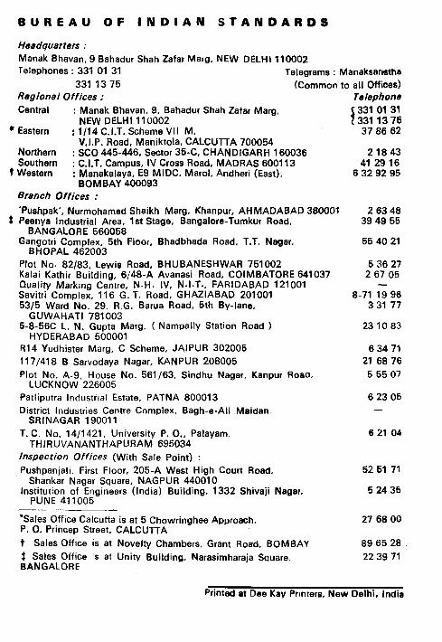
BUREAU OF INDIAN STANDARDS
tfeadqu8rters : Manak Bhavan, 9 Bahadur Shah Zafar Marg. NEW DELHI 110002
Telephones : 331 01 31 Telegrams : Manaksansths
331 I3 75 (Common to all Offices) Regionel Offices :
Central : Manak Bhavan. 9, Bahadur Shah Zafar Marg. NEW DELHI 110002
l Eastern : I/I4 C.I.T. Scheme VII M, V.I.P. Road, Maniktola. CALCUTTA 700054
Northern : SC0 445-446, Sector 35-C, CHANDIGARH 160036 Southern :
t Western CAT. Campus, IV Cross Road, MADRAS 600113
: Manakalaya, E9 MIDC. Marol. Andheri (East), BOMBAY 400093
Blench Offices :
‘Pushpak’, Nurmohamed Shaikh Marg. Khanpur, AHMADABAD 38000I t Peenya Industrial Area, 1st Stage, Bangalore-Tumkur Road,
BANGALORE 560058 Gangotri Complex, 5th Floor, Bhadbhada Road, T.T. Nagar.
BHOPAL 462003
Plot No. 82/83, Lewis Road, BHUBANESHWAR 751002 Kalai Kathir Building, 6/48-A Avanasi Road, COIMBATORE 641037 Quality Marking Centre, N.H. IV, N.I.T., FARIDABAD 121001 Savitri Complex, 116 G. T. Road, GHAZIABAD 201001 5315 Ward No. 29, R.G. Barua Road. 5th By-lane,
GUWAHATI 781003 5-8-56C L. N. Gupta Marg. ( Nampally Station Road )
HYDERABAD 500001 R14 Yudhister Marg, C Scheme, JAIPUR 302005
117/418 B Sarvodaya Nagar, KANPUR 208005
Plot No. A-9, House No. 561/63, Sindhu Nagar. Kanpur Roeo. LUCKNOW 226005
Patliputra Industrial Estate, PATNA 800013
District Industries Centre Complex, Bagh-e-Ali Maidan. SRINAGAR 190011
T. C. No. 14/1421, University P. O., Palayam. THIRUVANANTHAPURAM 695034
fnspection Offices (With Sale Point) : Pushpanjali. First Floor, 205-A West High Court Road.
Shankar Nagar Square, NAGPUR 440010 Institution of Engineers (India) Building, 1332 Shivaji Nagar.
PUNE 411005
‘Sates Office Calcutta is at 5 Chowringhee Approach, P. 0. Princep Street, CALCUTTA
t Sales Office is at Novelty Chambers, Grant Road, BOMBAY
dAafGe;Lgkf% is at Unitv Building. Narasimharaja Square
Telephone
i 331 01 31 331 I3 75 37 86 62
21843 41 29 16
6 32 92 95
2 63 48 39 49 55
55 40 21
5 36 27 2 67 05
-
8-71 19 96 3 31 77
23 10 83
6 34 71
21 68 76
5 55 07
6 23 05
6 21 04
52 61 71
5 24 35
27 66 00
89 65 28
22 39 71
Printed at Dee Kay Prmrers. New Delhi. India