is 10533 (1983): valve guides for internal combustion engines
TRANSCRIPT

Disclosure to Promote the Right To Information
Whereas the Parliament of India has set out to provide a practical regime of right to information for citizens to secure access to information under the control of public authorities, in order to promote transparency and accountability in the working of every public authority, and whereas the attached publication of the Bureau of Indian Standards is of particular interest to the public, particularly disadvantaged communities and those engaged in the pursuit of education and knowledge, the attached public safety standard is made available to promote the timely dissemination of this information in an accurate manner to the public.
इंटरनेट मानक
“!ान $ एक न' भारत का +नम-ण”Satyanarayan Gangaram Pitroda
“Invent a New India Using Knowledge”
“प0रा1 को छोड न' 5 तरफ”Jawaharlal Nehru
“Step Out From the Old to the New”
“जान1 का अ+धकार, जी1 का अ+धकार”Mazdoor Kisan Shakti Sangathan
“The Right to Information, The Right to Live”
“!ान एक ऐसा खजाना > जो कभी च0राया नहB जा सकता है”Bhartṛhari—Nītiśatakam
“Knowledge is such a treasure which cannot be stolen”
“Invent a New India Using Knowledge”
है”ह”ह
IS 10533 (1983): Valve guides for internal combustionengines [TED 2: Automotive Primemovers]


IS :10533 - 1983
Indian Standard
SPECIFICATION FOR
VALVE GUIDES FOR INTERNAL COMBUSTION ENGINES
Internal Combustion Engines Sectional Committee, EDC 14
Chairman Representing
BRIG J. K. KAPOOR Ministry of Defence ( DGI ), New Delhi
Members
MAJ-GEN S. S. APTE SHRI S. W. ATRB
The Institution of Engineers, Calcutta Kirloskar Cummins Ltd, Pune
SHRI R. S. DANDE~AR ( Alternate ) SHRI Y. M. BALAKRI~HNA
SRRI M. S. S. Jors ( Alternate ) Motor Industries Co Ltd, Bangalore
LT-COL B. K. BASU The National Small Industries Corporation Ltd, New Delhi
SRRI G. Y. BHATT The Permier Automobiles Ltd, Bombay SHRI V. P. TILAK ( Alternate J
SHRI S. B. CHANDORKA~ ’ Kirloskar Oil Engines Ltd, Pune SHRI N. N. NARAYAN RAO ( Alternate )
SHRI G. S. CHITNIS Indian Diesel Engines Manufacturers Association,
BRIG LOKESH DHAR Bombay
Central Institute of Road Transport ( T&R ), Pune DR G. V. RAMANIAR ( Alternate 1
’ SHRIDHANNA LAL SHRI G. S. Rno ( Alternate )
?‘ata Engg & Locomotive Co Ltd, Pune
DIRECTOR OF MARINE E~oa SHRI A. GROSH
Naval Headquarters, New Delhi National Test House, Calcutta
SHRI D. K. ROY ( Alternate J SHRI P. K. GOEL ’ ~_ ’
SHRI 1. P. NARANG ( Alternate ) Indian Oil Corporation Ltd, Faridabad
SHRI S. C. KAPOOR Directorate General of Supplies & Disposals ( Inspec- tion Wing ), New Delhi
SHRI S. K. GAUTAM ( Alternate ) SHRI S. S. KH~SLA Dirdctorate General of Technical Development,
New Delhi SHRI T. K. B. VERD~A ( Alternate )
SIIRI R. MA~A~EVAN India Pistons Ltd. Madras SHRI M. S. SESHADHRI ( Alternate )
PROF M. I,. MATHUI~ SHRI R. S. MISHRA
University of Jodhpur, Jodhpur ‘Garden Reach Shipbuilders & Engineers Ltd,
Calcutta SHRI V. K. BANSAL ( Alternate )
( Continued on paae 2 )
@ Copyright 1983 INDIAN STANDARDS INSTITUTION
This publication is protected under the Indian Copyright Act ( XIV of 1957 ) and reproduction in whole or in part by any means except with written permission of the publisher shall be deemed to be an infringement of copyright under the said Act.

IS:10533-1983
( Continued from page 1 )
Members Representing
ADDITIONAL DIRECTOR STAN- Research, Designs & Standards Organization, DARDS ( MP) (, SERI H. V. Lucknow MITTAL \
JOINT DIRECTOR STANDARDS ( SHRI KRISHAN KUMAR ) ( Alternate )
PROF K. NARAY ANASWAMY Indian Institute of Science, Bangalore PROF M. V. NAHASIMHAN ( Alternate )
SHRI B. P. PUNDIR Indian Institute of Petroleum ( CSIR ), Dehra Dun SHRI M. N. BANDOONI ( Alternate )
SHRI S. RAMACHANDARAN Mahindra & Mahindra Ltd, Bombay SHRI N. M. JOBANPUTRA ( Alternate )
SHRI R. RAMAKRISHNAN Ashok Leyland Ltd, Madras SHRI A. S. SUBRAMANIAN ( Alternate )
SHRI R. Rbma 4KRISHNAN Hindustan Aeronautics Ltd, Bangalore SHRI V. GOVINDAN ( Alternate )
SHRI D. G. K. REDDY Simpson & Co Ltd, Madras SHRI S. V. SASTRY The Automotive Research Association of India,
Pune SHRT Z. A. MUJAWAR ( Alternate j
SHRI A. N. SHARMA Ministry of Defence ( R & D ), Pune SHRI D. A. KHARE ( Alternate )
SHRI S. R. SHCME Central Mechanical Engineering Research Institute ( CSIR ), Durgapur
SHRI P. S. N. SuND.4RAM Cooper Engg ( Walchandnagar Industries Ltd ), Satara Road
SHRI W. N. KHATAVKAR ( Alternate ) SRRI D. D. SURYAWANSHI Ruston & Hornsby ( India ) Ltd, Bombay
SHRI P. S. SATWE ( Alternnle ) SHRI G. VISWANATHAN Ministry of Shipping & Transport, New Delhi SRRI P. S. DAS, Director General, IS1 ( Ex-ojicicio Member )
Director ( Mech Engg ) Secretary ,
SHRI SURINDER M. BHATIA Deputy Director ( Mech Engg ), ISI
Valves and Valve Guides Subcommittee, EDC 14 : 6
Convener
SRRI B. R. BALIGA
Members
Engine Valves Ltd, Madras
SHRI M. V. K. MURTHY ( Alternate to Shri B. R. Baliga )
SERI S. W. ATRE Kirloskar Cummins Ltd, Pune SHRI R. S. DANDEKAR ( Alternate )
DEPUTY DIRECTOR STANDARDS Research, Designs & Standards Organization,
( MD )-D3 Lucknow DEPUTY DIRECTOR STAN-
DARDS ( MD ) D-l ( Alternate )
( Continued on page 14 )
2

IS:10533 - 1983
lndian Standard SPECIFICATION FOR
VALVE GUIDES FOR INTERNAL COMBUSTION ENGINES
0. FOREWORD
0.1 This Indian Standard was adopted by the Indian Standards Institution on 24 February 1983, after the draft finalized by the Internal Combustion Engines Sectional Committee had been approved by the Mechanical Engineering Division Council.
0.2 This standard has been prepared to achieve some measure of rationalization of and interchangeability between the valving components for internal combustion engines for all types of applications ( except aircraft engines ). Materials and surface finish have also been specified to help the small scale engine and valve guide manufacturers in particular.
0.3 The present practice in the country is to design valve guides on Basic Hole System (see IS : 919-1963* ) and accordingly the dimensions and tolerances in this standard have been specified.
0.3.1 The Valves and Valve Guides Subcommittee, EDC 14 : 6 has felt that use of ‘Basic Shaft System’ of IS : 919-1963* could provide more flexibility to the consumer and may lead to valve guide interchange- ability from one engine to another resulting in rqductlon of large number of sizes of valve guides presently being used and manufactured in the country. Therefore, the committee recommends that designers should prefer to use the ‘Basic Shaft System’ to design the guides. The data collected as a result of the adoption of thiy ‘Basic Shaft System’ would be utilized in amending the standard.
0.4 Partial Standardization has been achieved by:
a) Specifying a range of valve guide bores related to the range of nominal valve stem diameters given in IS : 810-1974t, and
b) Specifying bores in the cylinder block or head to receive the valve guides.
*Recommendations for limits and fits for engineering ( revised ). )Specification for inlet and exhaust valves for internal combustion engines (Jirst
revision ) .
3
IS : 10533 - 1983
0.5 For the purpose of deciding whether a particular requirement of this standard is complied with, the final value, observed or calculated, expressing the result of a test, shall be rounded off in accordance with IS : 2-1960*. The number of significant places retained in the rounded off value should be the same as that of the specified value in this standard.
1. SCOPE
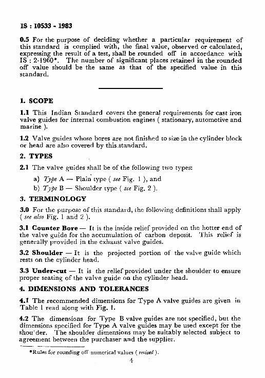
1.1 This Indian Standard covers the general requirements for cast iron valve guides for internal combustion engines ( stationary, automotive and marine ).
1.2 Valve guides whose bores are not finished to size in the cylinder block or head are also covered by this.standard.
2. TYPES
2.1 The valve guides shall be of the following two types:
a) Type A - Plain’ type ( see Fig. 1 ), and
b) Type B - Shoulder type ( see Fig. 2 ).
3. TERMINOLOGY
3.0 For the purpose of this standard, the following definitions shall apply ( see also Fig. 1 and 2 ).
3.1 Counter Bore - It is the inside relief provided on the hotter end of the valve guide for the accumulation of carbon deposit. This relief is generally provided in the exhaust valve guides.
3.2 Shoulder - It is the projected portion of the valve guide which rests on the cylinder head.
3.3 Under-cut - It is the relief provided under the shoulder to ensure proper seating of the valve guide on the cylinder head.
4. DIMENSIONS AND TOLERANCES
4.1 The recommended dimensions for Type A valve guides are given in Table 1 read along with Fig. 1.
4.2 The dimensions for Type B valve guides are not specified, but the dimensions specified for Type A valve guides may be used except for the shoulder. The shoulder dimensions may be suitably selected subject to agreement between the purchaser and the supplier. -.
*Rules for rounding off numerical values ( revised ).
4

1 + CHAMFER INSIDE I- A to.25
X to.1~ (OPTIONAL)
BORE
;”
FIG. 1 PLAIN TYPE ( TYPE 4 ) VALVE GUXDE

CHAMFER INSIOE X~0.15 (OPTIONAL)
-)-- ,- !ijHOULDER DIA D:, / “‘Y
UNDERCUT DEPTH
RADIUS R +-0.15
*Optional
FIG. 2 SHOULDER TYPE ( TYPE B ) VALVE GUIDE
I
5; E

NOMINAL BORE DIAMETER
Wl(H8)
t 7
8 9
10
11
12 -1 14
16
18
20
22
24
26
28
30
32
34
TABLE 1 DIMENSIONS OF VALVE GUIDES
( Clause 4.1 and Fig. 1 )
All dimensions in millimetres.
0 UTSIDE DIAMETER OF BORE DIAMETER To RECEIVE TIME
( NOMINAL SUIDE ( NOMINAL ) w ( 1~7 ) ( H7 )
11’5 11.5
12’5 12’5
13-5 13.5 15.5 15.0
16.5 16.5
18 18
20 20
22.5 22’5
25.5 25.5
28 28
32 32
345 345
37 37
39.5 39.5
44 44
47 47
50 50
53 53
T- PERMISSIBLE LENGTHS CHAMFER DEPTH
( NOMINAL ) Y, 5 t NOMINAL )
36 45 54
42 52 63
48 60 72 54 67 81 GO 7.5 90
G6 82 99
72 90 108
84 105 126 96 120 144
108 135 162
120 150 180
132 165 198
144 180 216 156 195 234
168 210 252
180 225 270
192 24C 288
204 255 306 I -
0.8
0.8
0.8
O-8 O-8
O-8
1.2
l-2
I.2
1.2
I.2
1.2
l-2
1.2
l-2
1.5
1.5
l-5

fS:10533-1983
4.3 The recommended tolerances on the various dimensions marked in Fig. 1 and 2 are given in Table 2.
TABLE 2 TOLERANCES ON Db.iBNSIONS OF VALVE GUIDES
DIMENSIONS
Outer diameter
Bore dimeter
Counter bore diameter
Counter bore depth
Concentricity between the bore and the outer diameter
Overall length
Grinding length
Under-cut depth
Under-cut radius
All outside chamfers
All inside chamkrs
All angular dimensions
REFERENCE IN I
TOLERANCE FIG. 1 AND 2 ~-
-
IT7
Hs
f 0.25 mm
* 0.25 mm
0.05 mm ( TIR )
Medium class of B&l02 (Part I )-
* 0’25 mm
f O-20 mm
f 0.15 mm
* 0.25 mm
f W15 mm
Coarse Class of Eko~102 (,Part I )-
*General tolerances for dimensions and form and position: Part I General tolerances for linear and angular dimensions ( second r&ion ).
4.4 The tolerance for diameter D ( see Fig. 1 and 2 ) may be suitably selected dependmg on the type of material used for the manufacture of valve guides and the cylinder head.
4.5 The deviations of taper, ovality, parallel shape and straightness shall be within the specified tolerances on corresponding dimensions.
4.6 The valve guide outer diameter is generally ground finished and the bore ream finished. However, other manufacturing processes may be followed to obtain the surface finish specified in 9.
4.7 Outside chamfers shall be 30°C. However, other chamfers required for special applications may also be used subject to agreement between the manufacturer and the purchaser.
8

1s : 10533 - 1983
5. MATERIAL
5.1 Valve guides shall be manufactured from good quality cast iron preferably produced from an electric furnace. The cast irons shall conform to the following standards:
a) Cast irons Grade FG 263 and Grade FG 300 according to IS : 210-1978*, and
b) Cast irons Grade 25 and Grade 30 according to IS : 6331-1971f', C) Cast irons Grade 2 and Grade 2 Type A according to IS : 3355-
1974:.
5.2 The valve guide material shall be free ‘from surface defects, such as shrinkage, pitting, scabbing, blow holes and any other similar defects which may affect reliability of valve guides in service.
6. MICRO STRUCTURE
6.1 The microstructure of the valve guide material shall be as follows:
*h'fICROSTRUC-
TURE I
MATERIAL
Grade FG 260, Grade 25 Grade FG 300, Grade 30 i and Grade 2 ( See 5.1 ) and Grade 2 Type A
( See 5.1 )
Graphite Form I, Distribution A, Form I, Distribution A, ( Determined Size 3 to 5 Size 3 to 5 according to
IS : 7754-1975s ) , Lamellar pearlite Lameller pearlite
Ferrite Less than Ferrite Less than ( if pre- 10 per- ( if pre- 5 percent
cent Matrix ,
sent ) sent ) Carbides I Less than Carbides ( Less than
I 5P ercent 1 5 percent
Phosphide Uniformly Phosphide Unifbrmly eutectic distribut- eutectic distributed
ed
6.2 In the case of highly rated and pressure charged engines for which special materials are used ( subject to agreement between the purchaser and the supplier ) microstructural examination is an important criteria
*Specification for grey iron castings ( third revision ). Wpecification for automotive grey iron castings. JSpecification for grey iron castings for elevated temperatures for non-pressure
containing parts (first reuision ) . §Method for designation of the microstructure of graphite in cast iron.
9
IS: 10533 -1983
for acceptance of materials for the manufacture of valve guides. In such cases the limits on the micro-structural constituents shall be mutually agreed to between the purchaser and the supplier.
7. HARDNESS
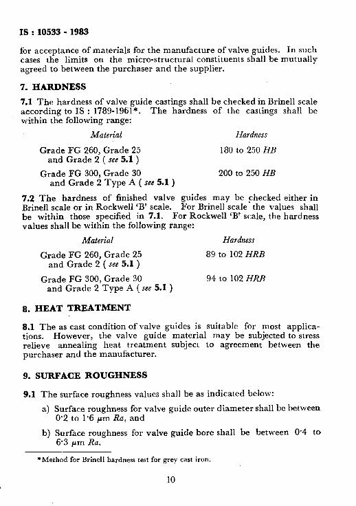
7.1 The ‘hardness of valve guide castings shall be checked in Brine11 scale according to IS : 1789-1961*. The hardness of the castings shall be within the following range:
Material Hardness
Grade FG 260, Grade 25 180 to 250 HB and Grade 2 ( see 5.1 )
Grade FG 300, Grade 30 200 to 250 HB and Grade 2 Type A ( see 5.1)
7.2 The hardness of finished valve guides may be Fhecked either in Brine11 scale or in Rockwell ‘B’ scale. For Brine11 scale the values shall be within those specified in 7.1. For Rockwell ‘B’ scale, the hardness values shall be within the following range:
Material Hardness
Grade FG 260, Grade 25 89 to 102 HRB and Grade 2 ( see 5.1 )
Grade FG 300, Grade 30 94 to 102 HRB and Grade 2 Type A ( see 5.1 )
8. HEAT TREATMENT
8.1 The as cast condition of valve guides is suitable for most applica- tions. However, the valve guide material may be subjected to stress relieve annealing heat treatment subject to agreement between the purchaser and the manufacturer.
9. SURFACE ROUGHNESS
9.1 The surface roughness values shall be as indicated below:
a) Surface roughness for valve guide outer diameter shall be between 0.2 to I.6 pm Ra, and
b) Surface roughness for valve guide bore shall be between 0.4 to 6.3 pm Ra.
*Method for Brine11 hardness test for grey cast iron.
10

IS : 10533 - 1983
9.1.1 In case finer roughness values are required for special applica- tions this shall be subject to agreement between the purchaser and the manufacturer.
9.2 Surface roughness inspection shall be carried out in accordance with IS : 3073-1967.*
10. ACCEPTANCE
10.1 All the dimensions and requirements in accordance with this standard shall be checked at the final inspection by the manufacturer.
10.2 On the finished valve guides a certain number of imperfections such as porosity may be considered acceptable provided such inperfections have no deleterious effect on the serviceability of the valve guides. The size, location and maximum number of imperfections acceptable are given in Appendix A.
11. MARKING 1
11.1 Each valve guide shall be legibly and indelibly marked with the name ( brand or other ) of the manufacturer, part number and batch number. The markings shall be such that they do not affect the function of the valve guides.
11.2 The valve guides may also be marked with the IS1 Certification Mark.
NOTE - The use of the IS1 Certification Mark is governed by the provisions of the Indian Standards Institution ( Certification Marks ) Act and the Rules and Regu- lations made thereunder. The IS1 Mark on products covered by an Indian Standard conveys the assurance that they have been produced to comply with the requirements of that standard under a well-defined system of inspection, testing and quality control which is devised and supervised by IS1 and operated by the producer. IS1 marked products are also continuously checked by IS1 for conformity to that standard as a further safeguard. Details of conditions under which a licence for the use of the IS1 Certification Mark may be granted to manufacturers or processors, may be obtained from the Indian Standards Institution.
12. PRESERVATIVE TREATMENT
12.1 Each valve guide shall be coated with a suitable anticorrosive oil or medium. Alternatively, valve guides could be preserved with the aid of suitable chemically-treated papers.
13. PACKING
13.1 Valve guides shall be packed individually in polyethene or paraffin paper or equivalent bags. They shall then be packed in cardboard cartons in numbers as mutually agreed to between the purchaser and the supplier.
*Assessment of surface roughness.
11

IS:10533-1983
APPENDIX A ( Clause 10.2 $
ACCEPTANCE STANDARDS FOR POROSITY IMPERFECTIONS IN VALVE GUIDES
A-l. TERMINOLOGY
A-l.1 Pinpoint Porosity - Pinpoint porosity consists of specks of a pepper type appearance with a maximum diameter of O-38 mm and a maximum depth of 0.25 mm.
A-1.2 Major Porosity - Major porosity is classified into two classes:
I Small imperfection / Above 0.38 mm up to O-8 mm diameter Large imperfection 1 Above 0.8 mm up to 1.6 mm diameter -_ I
A-2. ACCEPTANCE STANDARDS A-2.1 Pinpoint porosity is acceptable on all surfaces except on oil scraper point ( see Fig. 3 ).
A-2.2 Outside Diameter f see Fig. 3 1 - On outside surface follow- ing level of imperfection is acceptable: ’ -.-
Maximum number of imperfections
I
10 ( total ) on the valve guide outside ( small imperfections - 5) surface ( large imperfections - 5 )
Minimum space between any two 3.2 mm imperfections
A-2.3 Bevelled Square End and Valve Guide Bore ( see Fig. 3 ) - On bevelled square ends and valve guide bores following level of imper- fection is acceptable: _--
Maximum number of imperfections I
6 ( large and small ) on bevelled square end
Maximum number of imperfections
I 6 ( large and small )
on value guide bore Minimumpace between any two
imperfections on bevelled square end and valve guide bore
6.4 mm
A-2.4 Oil Scraper Point - On oil scraper point no imperfection is permissible.
12

-_ .
“Ev OVERALL LENGTH L -1
__-___-_- ______________-__-_-______ SQ EN
_--- _ p_-
OVERALL LENGTH L
FIG. 3 LOCATIONS OF IMPERFECTIONS E . .
5: 01 E I
5: 8’
IS : MB33 - 1983
( Continued from page 2 )
Members Representins
SHRI DHANNA LAL Tata Engg & Locomotive Co Ltd, Pune . SHRI G. S. RAO ( Alternate )
Snnr M. GHAZNAVI Oil India Ltd, Duliajan SHRI D. C. GOSWAMI ( Alternate )
DR B. S. KUMAR * Escorts Ltd, Faridabad SHRI N. V. IYER ( Alternate )
SRRI S. J. MAHATRE Perfect Engg Products Ltd, Bombay LT-COL S. K. MEHRA Ministry of Defence ( DGI )
MAJ MANDER ( Alternate ) SHRI J. S. MUDHAR Hindustan Machine Tools Ltd, Pinjore
SHRI S. C. GUPTA ( Alternate) SRRI A. K. MURHOPADHYAY The Acme Manufacturing Co Ltd, Bombay
SRRI R. K. KANWAL ( Alternate ) SHRI B. C. MURALI Ashok Leyland Ltd, Madras SHRI S. MURALIDHARAN Simpson & Co Ltd, Madras SRRI N. S. NAOARATHNAM Ministry of Defence ( R & D )
SHRI P. L. SATHYANARAYANA ( Alternate ) SHRI P. S. SATWE
SRRI R. SIRPAL ( Alternate ) Ruston & Hornsby ( India ) Ltd, Pune
SHRI D. M. SHAH SHRI A. D. DANI ( Alternate )
Kirloskar Oil Engines Ltd, Pune
SHRI N. V. R. SHARMA Garden Reach Shipbuilders & Engineering Ltd, Calcutta
SHRI P. D. SOMAN Inex Engine Valves Ltd, Pune SHRI S. D. NILAPAWAR ( Alternate )
SHRI P. S. N. SUNDARA~V Cooper Engg ( M/s Walchandnagar Industries Ltd ), Satara Road
SHRI W. N. KHATAVEAR ( Alternate )
14