is 13235.1991.pdf
DESCRIPTION
Indian standard for stc calculationsTRANSCRIPT

Disclosure to Promote the Right To Information
Whereas the Parliament of India has set out to provide a practical regime of right to information for citizens to secure access to information under the control of public authorities, in order to promote transparency and accountability in the working of every public authority, and whereas the attached publication of the Bureau of Indian Standards is of particular interest to the public, particularly disadvantaged communities and those engaged in the pursuit of education and knowledge, the attached public safety standard is made available to promote the timely dissemination of this information in an accurate manner to the public.
इंटरनेट मानक
“!ान $ एक न' भारत का +नम-ण”Satyanarayan Gangaram Pitroda
“Invent a New India Using Knowledge”
“प0रा1 को छोड न' 5 तरफ”Jawaharlal Nehru
“Step Out From the Old to the New”
“जान1 का अ+धकार, जी1 का अ+धकार”Mazdoor Kisan Shakti Sangathan
“The Right to Information, The Right to Live”
“!ान एक ऐसा खजाना > जो कभी च0राया नहB जा सकता है”Bhartṛhari—Nītiśatakam
“Knowledge is such a treasure which cannot be stolen”
“Invent a New India Using Knowledge”
है”ह”ह
IS 13235 (1991): Calculation of the Effects ofShort-circuit Currents [ETD 20: Electrical Installation]


- -
Indian Standard
IS 13235 : 1991 EC Pub 885 ( 1988 ) ( Superseding IS 6726 1
(Reaffkmed 1997)
CALCULATION OF THE EFFECTS OF SHORT-CIRCUIT CURRENTS
( First Reprint FEBRUARY 1999 )
UDC 621-317-613
BUREAU OF INDIAN STANDARDS MANAK BHAVAN, 9 BAHADUR SHAH ZAFAR MAR0
NEW DELHI 110002
December 199 1 Rice Group 10
( Reaffirmed 2002 )

IS 13235 I 1991
IECPob865(1986)
Indian Standard
CALCULATION OF THE EFFECTS OF SHORT-CIRCUIT CURRENTS
NATIONAL FOREWORD
This Indian Standard which is identical with IEC Pub 865 ( 1986 ) Calculation of the effects of short-circuit currents’, issued by the International Electrotechnical Commission ( IEC ) was adopted by the Bureau of Indian Standards on the recommendations of the Electrical Installations Sectional Committee ( ET 20 ) and approval of the Electrotechnical Division Council.
An important criterion for the proper selection of a circuit-breaker or any other fault protective devices for use at a point in an electrical circuit is the information on maximum fault current likely at that point. The electromagnetic, mechanical and thermal stresses which a switchgear and the associated apparatus have to withstand depends on the fault current. of breaking and withstand capacities play a major role in
Proper selection e health of the electrical installa-
tions. Realizing this need and to provr e +i uniform g P ide fo. calculation of short-circuit currents, IS 5728 was brought out in 1970.# ;, .,,
Subsequent to the preparation of this standa d, considerable information has been collated the world over on calculation of fault levels under different and specific circumstances. There was also a need to simplify calculation techniques in practical way commensurate with the modern arithmetic tools available to engineers in the form of computers, digital transient network analysers etc. With an objective to establish a general, practicable and concise procedure for short-circuit current calculations IS 5728 has been taken up for revision, aligning its contents with IEC 865 ( 1986 ).
This Indian Standard supplements the provisions of IS 13234 : 199l/IEC 909 (1988) by covering standardized procedures for the calculation of the electromagnetic and thermal effects of fault currents in electrical circuits.
1

As in the Original Standard, this Page is Intentionally Left Blank
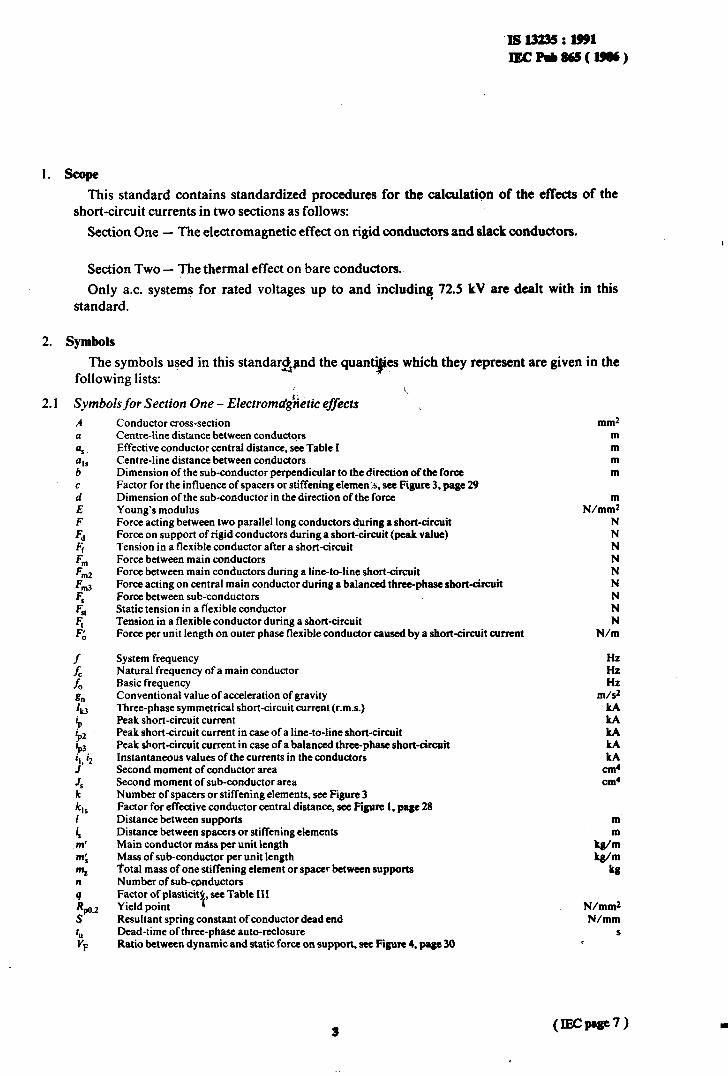
1. scope This standard contains standardized procedures for the calculation of the effects of the
short-circuit currents in two sections as follows:
Section One - The electromagnetic effect on rigid conductors and slack conductors.
Section Two - The thermal effect on bare conductors..
Only a.c. systems for rated voltages up to and ‘including 72.5 kV are dealt with in this . standard.
2. Symbols
The symbols used in this standaragnd the quanti$es which they represent are given in the following lists:
2.1 Symbols for Section One - Electromdgketic effects ‘k.
A (I
4. % b c d E F
Fd 4 Fl F In2 F m3
F,
4t
4 F 0
::
2
g”
‘k3
i;
i, iz
JS Js k k,, 1
4 m’
m; m, n 4 Q.2 S
6
VF
Conductor cross-section Centre-line distance between conductors Effective conductor central distance, see Table I Centre-line distance between conductors Dimension of the sub-conductor perpendicular to the direction of the force Factor for the influence of spacers or stiffening elemen:s, see Figure 3, page 29 Dimension of the sub-conductor in the direction of the force Young’s modulus Force acting between two parallel long conductors duringr short-circuit Force on support of rigid conductors during a short-circuit (peak value) Tension in a flexible conductor after a short-circuit Force between main conductors Force between main conductors durmg’a line-to-line short-circuit Force acting on central main conductor during a balanced three-phase short-circuit Force between sub-conductors Static tension in a flexible conductor Tension in a flexible conductor during a short-circuit Force per unit length on outer phase flexible conductor caused by a short-circuit current
System frequency Natural frequency of a main conductor Basic frequency Conventional value of acceleration of gravity Three-phase symmetrical short-circuit current (r.m.s.) Peak short-circuit current Peak short-circuit current in case of a line-to-line short-circuit Peak short-circuit current in case of a balanced three-phase short-circuit Instantaneous values of the currents in the conductors Second moment of conductor area Second moment of sub-conductor area Number of spacers or stiffening elements, see Figure 3 Factor for effective conductor central distance, see Figure I, page 28 Distance between supports Distance between spacers or stiffening elements Main conductor mass per unit length Mass of sub-conductor per unit length Total mass of onestiffening element or spacer between supports Number of sub-conductors Factor of plasticit see Table III Yield point +
Resultant spring constant of conductor dead end Dead-time of three-phase auto-reclosure Ratio between dynamic and static force on support, see Figure 4. page 30
mm2 m m m m
N/m; N N N N N N N N N
N/m
HZ HZ HZ
m/s2 kA LA LA kA kA
cm4
cm4
m
kg/: kdm
kg
N/mm2 N/mm
S .
IS 13235 : 1991 IECPub865(19S)
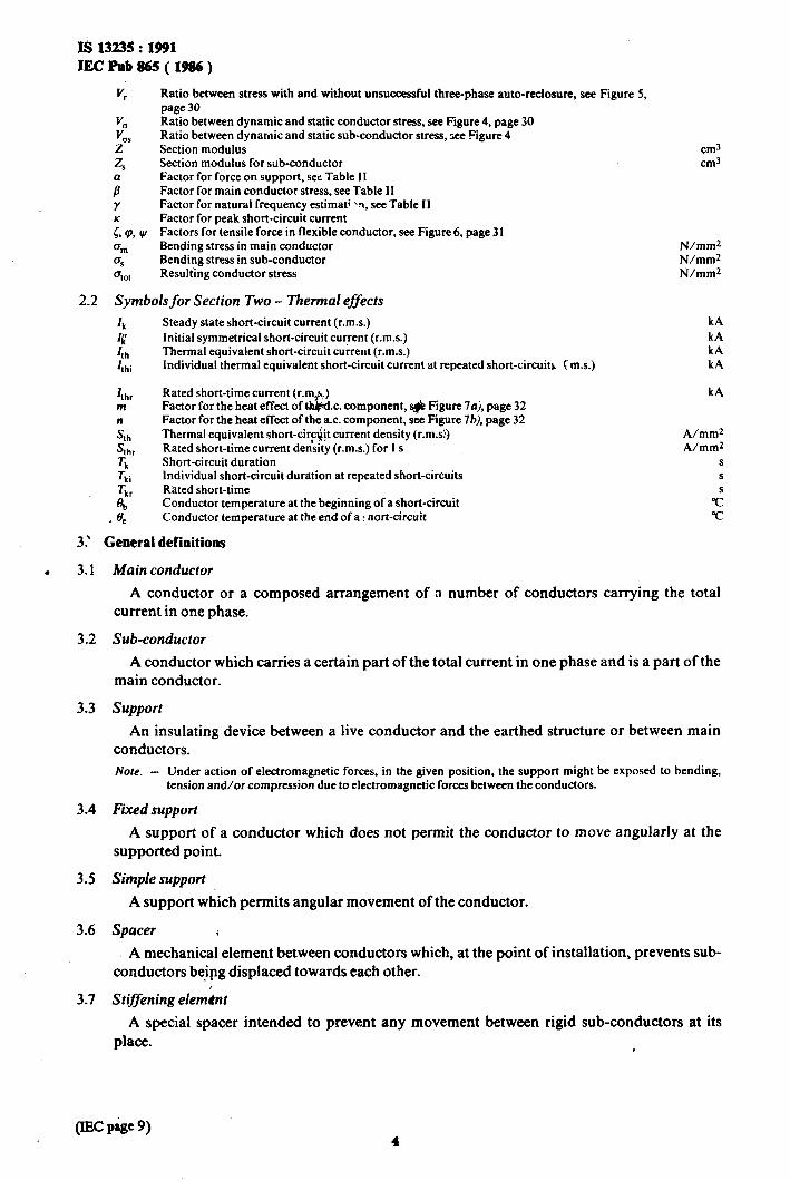
V, Ratio between stress with and without unsuccessful three-phase auto-reclosure. see Figure 5, page 30
V, Ratio between dynamic and static conductor stress, see Figure 4, page 30 V cls Ratio between dynamic and static sub-conductor stress, see Figure 4 Z Section modulus Z, Section modulus for sib-conductor
a* Factor for force on support, see Table II Factor for main conductor stress, see Table II
Y Factor for natural frequency estimat; ‘7, see Table II
E p, ly Factor for peak short-circuit current Factors for tensile force in flexible conductor, see Figure 6, page 3 I
um Bending stress in main conductor 0, Bending stress in sub-conductor a,,, Resulting conductor stress
2.2 Symbols for Section Two - Thermal effects
cm3 cm3
N/mm2 N/mm* N/mm2
3.’
. 3.1
3.2
3.3
3.4
3.5
3.6
3.7
Ik Steady state short-circuit current (r.m.s.) I[ Initial symmetrical short-circuit curient (r.m.s.) I I:Li
Thermal equivalent short-circuit current (r.m.s.) Individual thermal equivalent short-circuit current at repeated short-circuits (m.s.)
I thr Rated short-time current (r.ma.) m Factor for the heat effect of t&d.c. component, # Figure 7aj, page 32
ih
Factor for the heat effect of the a.c. component, see Figure 761, page 32 Thermal equivalent short-circ&t current density (r.m.s!)
S thr Rated short-time current de&ity (r.m.s.) for I s & Short-circuit duration Tki Individual short-circuit duration at repeated short-circuits % Rated short-time
2 Conductor temperature at the beginning of a short-circuit
* e Conductor temperature at the end of a : nort-circuit
General definitions
kA kA kA kA
kA
A/mm2 A/mm2
S
S
G
T
Main conductor
A conductor or a composed arrangement of a number of conductors carrying the total current in one phase.
Sub-conductor
A conductor which carries a certain part of the total current in one phase and is a part of the main conductor.
support
An insulating device between a live conductor and the earthed structure or between main conductors.
Note. - Under action of electromagnetic forces, in the given position, the support might be exposed to bending, tension and/or compression due to electromagnetic forces between the conductors.
Fixed support
A support of a conductor which does not permit the conductor to move angularly at the supported point.
Simple support
A support which permits angular movement of the conductor.
Spacer E
! A mechanical element between conductors which, at the point of installation, prevents sub- conductors be&g displaced towards each other.
Stiffening elemknt
A special spacer intended to prevent any movement between rigid sub-conductors at its place. I
IS 13235 : 1991 IECPab865(1986j
3.8 Rated short-time current
The r.m.s. current which the electrical equipment is able to withstand during the rated short-time under specified conditions. Notes 1. - It is possible to state several pairs of values of rated short-time current and short-time; for thermal effect
I s is used in most I EC specifications.
2. - The rated short-time current as well as the correspouding short-time are stated by the manufacturer of the equipment.
3.9 Rated short-time current density and rated short-timefor conductors
The r.m.s. value of the current density which a conductor is able to withstand for the rated short time. Note. - The rated short-time current density is determined according to Clause 10.
3.10 Thermal equivalent short-circuit current
A constant r.m.s. value of current having the same thermal effect and the same duration as the actual short-circuit current, which may comprise d.c. component and may subside in time.
Note. - If repeated short-circuits occur (i.e. rwated reclosures) YesuIting thermal equivalent short-circuit current is evaluated (see Sub-clause 10.2).
3.11 Thermal equivalent short-circuit currentdensity ‘,,
The ratio of the thermal equivalent short-time current and the cross-section area of the conductor.
3.12 Duration of short-circuit current
The time interval between the initiation of ti e short-circuit and the final breaking of the current in all phases by the circuit-breakers or fuses. NOW. - The time interval in which the current does not flow need qot be considered.
SECTION ONE - THE ELECTROMAGNETIC EFFECT ON RIGID CONDUCTORS AND SLACK CONDUCTORS
4. General
With the calculation methods presented in this section, forces on insulators, stresses in rigid conductors and tensile forces in slack conductors can be estimated.
5. Mechadcalforces due to short-circuit currents
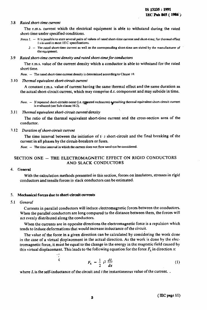
5. I General
Currents in parallel conductors will induce electromagnetic forces between the conductors. When the parallel conductors are long compared to the distance between them, the forces will act evenly distributed along the conductors.
When the currents are in opposite directions the electromagnetic force is a repulsion which tends to induce deformations that would increase inductance of the circuit.
The value of the force in a given direction can be calculated by considering the work done in the case of a virtual displacement in the actual direction. As the work is done by the elec- tromagnetic force, it must be equal to the change in the energy in the magnetic field caused by this virtu’al displacement. This leads to the following equation for the force F, in direction x
(1)
where L is the self-inductance of the circuit and i the instantaneous value of the current. .
( mc page 11)

IS 13235 : 1991
IECPob845(1981)
For simple and idealized configurations, formulae for the calculation of inductance are available. However, in most cases approximations are necessary to give practical calculation methods.
The force between two conductors is proportional to the square of the current, or to the product of the two currents. As the current is a function of time, the force will also be a function of time. In the case of a short-circuit current without a d.c. component the force will vary with twice the frequency of the current. A d.c. component in the short-circuit current will give rise to an increase of the peak value of the force and to a component of force varying with the same frequency as the current. The peak value of the force is of particular interest in the case of mechanically rigid structures.
The force will result in bending stress on rigid conductors, tension stress and deflection in flexible conductors and bending, compression or tension loads on the supports.
5.2 Calculation offorces The calculation method in this section is based on the general equation (l), neglecting the
variations in distance during tkdshort-circuit. d
5,2.1 Forces between two parallel coh&uctors
The forces in newtons acting between two long. parallel conductors are given by the formula:
F=0.2ilhA N (2)
where I is the distance, in metres, between supports, il and i;! are the instantaneous values of the currents in the conductors in kiloamperes, a is the centre-line distance between the conductors in metres.
When the currents in the two conductors have the same direction, the forces are attractive. When the direction of the currents is opposite, the forces are repulsive.
5.2.2 Calculation of peak force between the main conductors during a three-phase short-circuit
In a three-phase system with the conductors arranged at the same intervals on the same plane, the maximum force acts on the central conductor during a three-phase short-circuit and is:
F m3 - 0.2 i& -!- 0.87 N (3) as
where.63 in kiloamperes is the peak value of the a.c. component of the short-circuit current in the case of a balanced three-phase short-circuit. Nore. - Formula (3) can also be used for calculating the resulting peak force when the conductors arc in the comers
of an quilateral triangle and where 4 is the length of the side of the triangk.
52.3 Calculation of peak force between the main conductors during a two-phase short-circuit
The maximum force acting between the conductors carrying the short-circuit current during a two-phase short-circuit is:
L F *2 1 m2 - 0.2 lP2 - N
as where ip2.in kiloamperes is the peak short-circuit current in the case of a line-to-line short- circuit. .
(IEC page 13) 6

IS I3235 : 1991
TECl’ub865(1986),
5.2.4 Calculation ofpeak value offorces between rigid sub-conductors
The maximum force acts on the outer sub-conductors and is between two spacers:
when the short-circuit current is evenly distributed between the sub-conductors; n is the number of sub-conductors, I, is the distance between spacers or stiffening elements, in metres, and a, is the effective distance between sub-conductors, in metres.
52.5 Effective distance between conductors and sub-conductors
The forces between current-carrying conductors are dependent on the geometrical conligur- ation and the profile of the conductors. For this reason a, has been introduced in Sub- clauses 5.2.2, 5.2.3 and 5.2.4. However, if the dimensions of the cross-sections of the conductors are smaller than the distance between the conductor centres, in Sub-clauses 5.2.2 and 5.2.3 a, may be replaced by a.
4 \
Some values for a, are given in Table I. For other Astances and conductor dimensions the formula I 1.
c.
1 kt2 kt3 kt4 kt, -P -.+ a,
-+- + . . . + - ai2 a13 aI4 ain
(6)
can be used
The values for k12, . . . . kin are to be taken from Figure 1, page 28. Note. - The forces due to bends and the influence of a large amount of magnetic material close to the conductors
are usually of low importance. For the calculations, see existing publications.
6. Calculation of stresses in rigid conductors and forces on supports
6.1 General
The conductors may be supported in different manners, either fixed or simple or in 5: combination of both, and may have two, three, four or several supports. Depending on the kind of support and the number of supports, the stress in the conductors and the forces on the supports will be different for the same short-circuit current. The formulas given also take the elasticity of the supports into account.
The stresses in the’conductors and the forces on supports also depend on the ratio between the natural frequency of the mechanical system and the frequency of the electromagnetic force. Especially in the case of resonance, or near to resonance, the stresses and forces in the system may be amplified.
6.2 Calculation of stresses in iigid conductors
The assumption that the conductor,,is rigid means that the axial forces are disregarded. Under this assumption the forces acting are bending forces and the general formula for the bending stress in the supported main conductor is:
Frnl urn= &rV,B - N/mm2 , 8Z
(7)
where for F, either the value Fm3 (three-phase short-circuit) or Fm2 (line-to-line short-circuit) is to be used. , I
The bendingstress ida sub-conductor is:
*s a Gs V, 45
- N/mm2 16z,
, (8)
IS 13235 : 1991
IECPnb865(1986)
e
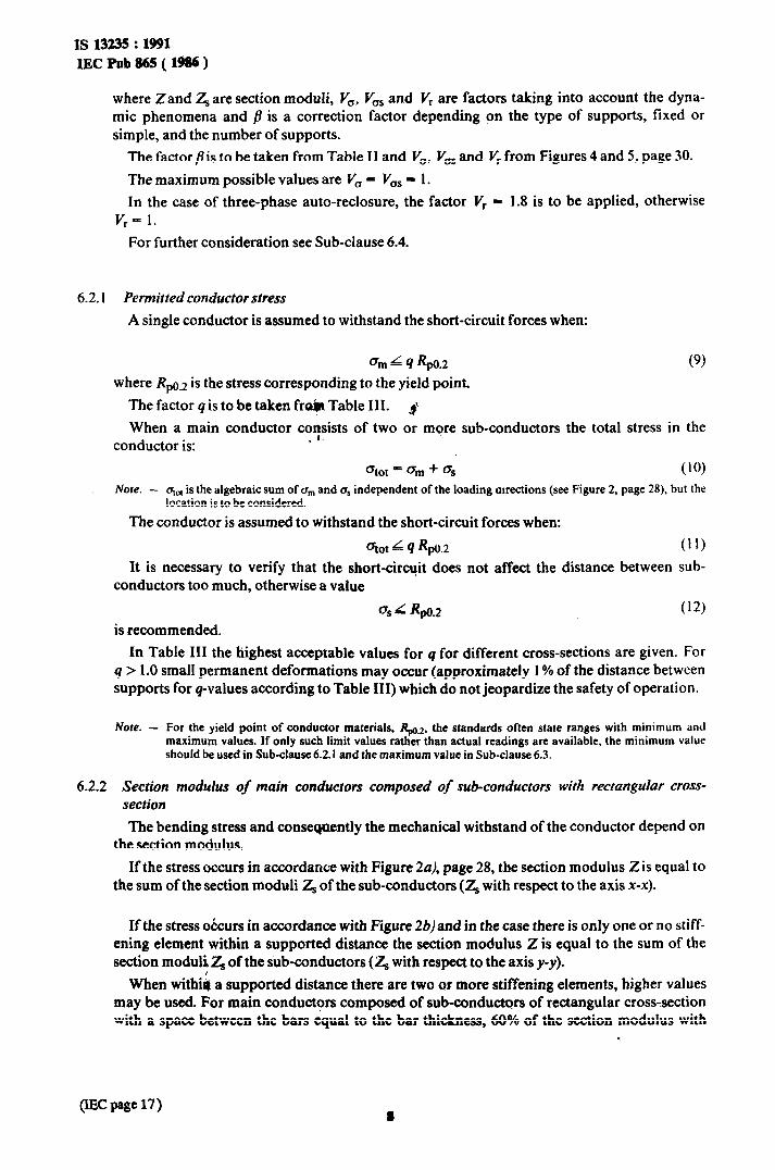
where Zand Z, are section moduli, V,, V,, and Vr are factors taking into account the dyna- mic phenomena and B is a correction factor depending on the type of supports, fixed or simple, and the number of supports.
T’he factor pis to be taken from Table II and V,, V, and Vr from Figures 4 and 5, page 30. The maximum possible values are V, - V,, - 1. In the case of three-phase auto-reclosure, the factor Vr - 1.8 is to be applied, otherwise
If,- 1. For further consideration see Sub-clause 6.4.
6.2.1 Permitted conductor stress
A single conductor is assumed to withstand the short-circuit forces when:
cm L 4 40.2 (9)
where R,o.J is the stress corresponding to the yield point. The factor q is to be taken fr&r Table III. p When a main conductor coysists of two or more sub-conductors the total stress in the
conductor is:
otot = urn + G (10)
Nore. - or,, is the algebraic sum of a,,, and crS independent of the loading atrections (see Figure 2, page 28). but the location is to be considered.
The conductor is assumed to withstand the short-circuit forces when:
atot L 4 50.2 (11)
It is necessary to verify that the short-circuit does not affect the distance between sub- conductors too much, otherwise a value
os L 40.2 (12)
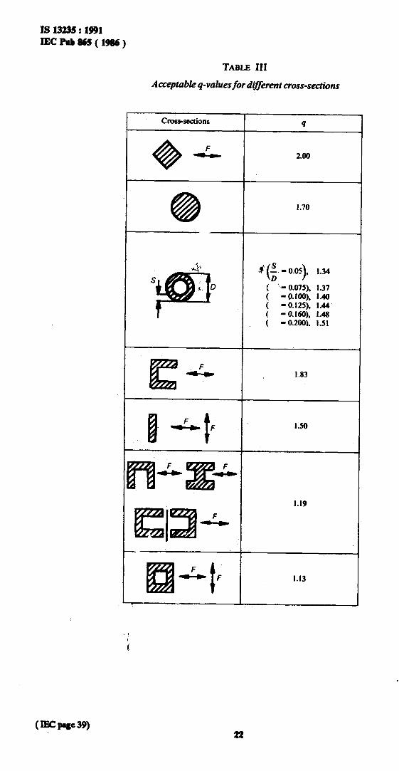
is recommended. In Table III the highest acceptable values for q for different cross-sections are given. For
q > 1.0 small permanent deformations may occur (approximately 1% of the distance between supports for q-values according to Table III) which do not jeopardize the safety of operation.
Note. - For the yield point of conductor materials, Q.2, the standards often state ranges with minimum and maximum values. If only such limit values rather than actual readings are available, the minimum value should be used in Sub-clause 6.2.1 and the maximum value in Sub-clause 6.3.
6.2.2 Section modulus of main conductors composed of sub-conductors with rectangular cross- section The bending stress and conseqnently the mechanical withstand of the conductor depend on
the section modulus. If the stress occurs in accordance with Figure 2a), page 28, the section modulus 2 is equal to
the sum of the section moduli Z, of the sub-conductors (Z, with respect to the axis x-x).
If the stress occurs in accordance with Figure 2b)and in the case there is only one or no stiff- ening element within a supported distance the section modulus 2 is equal to the sum of the section modul! Z, of the sub-conductors (Z, with respect to the axis y-y).
When withiq a supported distance there are two or more stiffening elements, higher values may be used. For main conductors composed of sub-conductors of rectangular cross-section with a space between the bars equal to the bar thickness, 60% of the section modulus with
PI= Page 17 )

IS 13235 : 1991
IEC Pub 865 ( 1986
respect to the axis O-O may be used. For conductor groups having profile cross-section, approximately 50% of the section modulus with respect to the axis O-O may be used. See Table IV.
6.3 Calculation offorces on supports of rigid conductors
The dynamic force Fd is to be calculated from:
Fd = VF J’raFrn
where for F, either the value Fm3 or F,.,Q is to be used.
The maximum possible values of I+ - V, can be estimated as follows:
v,* v,- 1 when o, + a, >0.8 Rpc.2
(13)
v,- VF- O-8 Rp0.2
grn + 0s when a,,, + o, d 0.8 R,,u.2
The value of VF. V, is not higher than 2.7 for a three-phase short-circuit, and 2.0 for a two- phase short-circuit.
For further consideration.see Sub- &use 6.4. p
The factor a is dependent on the kind and the number of supports and is to be taken from Table II. See Note 2 to Table II. Regarding permitted load on insulator, see Clause 8.
6.4 Calculation with special regard to conductor oscillation
The formulae in Sub-clauses 6.2 and 6.3 give bending stresses and forces on supports achieved from a calculation of a load which is as- umed static. In Sub-clauses 6.2 and 6.3 three factors, V,, VF and V, are introduced to take into account the natural frequency of the conductor. Some figures are also given for V,, V, and V, which give the highest possible stresses and forces.
6.4.1 Calculation_ojrelevant naturalfrequency
The relevant natural frequency of a single conductor can be calculated from:
(14)
The factor y is dependent on the kind and number of supports and is given in Table II.
For a main conductor composed of sub-conductors, J and m’ must apply to the main conductor design. If the sub-conductors are of rectangular cross-section the relevant natural frequency of the main conductor can also be calculated as:
where:
The factor c is to be’taken from graph a) or b) of Figure 3, page 29. In the case of no stiff- ening elements c = 1.
For the calculatid$ of sub-conductor stress, taking the relevant natural frequency into account, the formula (14) is to be used. In this case replace Iby 4, m’ by mg and J by .I, and use y = 0.356. Note. - The second moments Jand J, are calculated according to Figures 2a)or 2b). page 28. *
9 (IEC page 19)
JS 13235 : 1991 IEC Pub 865 ( 1986 )
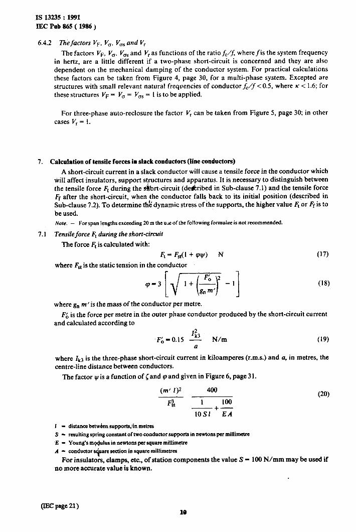
6.4.2 Thefactors V,, V,, V,, and V,
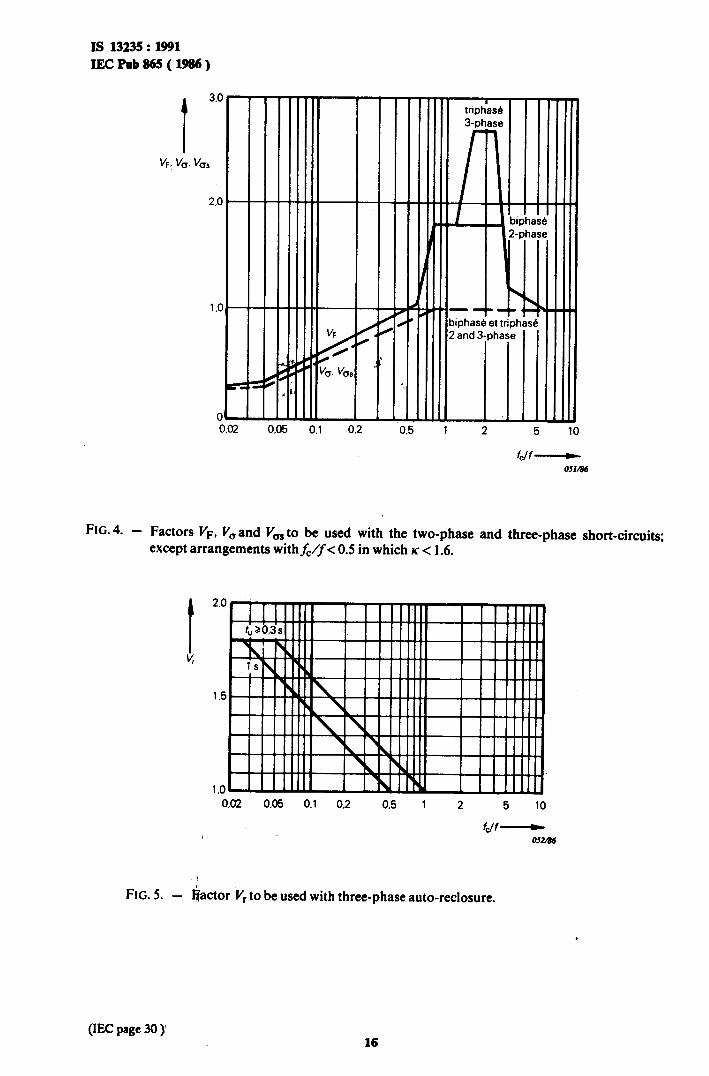
The factors VF, V,, V,, and V, as functions of the ratio fC/’ where f is the system frequency in hertz, are a little different if a two-phase short-circuit is concerned and they are also dependent on the mechanical damping of the conductor system. For practical calculations these factors can be taken from Figure 4, page 30, for a multi-phase system. Excepted are structures with small relevant natural frequencies of conductor fc/f < 0.5, where K < 1.6; for these structures VF = V, = V,, = 1 is to be applied.
For three-phase auto-reclosure the factor V, can be taken from Figure 5, page 30; in other cases V, = 1.
7. Calculation of tensile forces in slack conductors (line conductors)
A short-circuit current in a slack conductor will cause a tensile force in the conductor which NilI affect insulators, support structures and apparatus. It is necessary to distinguish between the tensile force Ft during the &rt-circuit (de&ribed in Sub-clause 7.1) and the tensile force F’ after the short-circuit, when .the conductor falls, back to its initial position (described in Sub-clause 7.2). To determine t& dynamic stress of the supports, the higher value Ft or Ff is to be used. Note. - For span lengths exceeding 20 m the u;e of the following formulae is not recommended.
7.1 Tensile force Ft during the short-circuit
The force 4 is calculated with:
Ft = F,(l + W) N (17) where F,, is the static tension in the conductor
9-3[d-55-1] (18)
where g, M’ is the mass of the conductor per metre.
F;, is the force per metre in the outer phase conductor produced by the short-circuit current and calculated according to
123 F&-O.15 - N/m (1%
a
where Zk3 is the three-phase short-circuit current in kiloamperes (r.m.s.) and u, in metres, the centre-line distance between conductors.
The factor vis a function of Cand cp and given in Figure 6, page 3 1.
(m’ I)2 400
Fit 1 100 -+-
lOS1 EA
(20)
I - distance betw&m supports,tin metres
9 - resulting spring constant of two conductor supports in newtons per millimetre
E - Young’s mpQulus in newtons per square millim+e
A - conductor s+are section in square millimetres
For insulators, damps, etc., of station components the value S - 100 N/mm may be used if no more accurate value is known.
10

IS 13235 : 1991 IECPab865(1986)
7.2 Tensileforce Ff after the tiort-circuit ($a11 of span)
This force is only considered when:
F;, > 0.6 g0’
(21)
In this case is to be applied:
Ff = F&O 4-c if -!!- >2 (23) g0’
where Fst6c is the static tension in the conductor at a conductor-temperature of 60°C. Notes 1. - The resonance frequencies of these flexible conductors are low, and higher forces due to resonance are
not expected.
2. - Due to conductor motion the stres may be lower than,given by the formulae. The use of lower stress is acceptable when it can be demons&t . ed etther by calct&rtion or by tests.
3. - In the case of twin-conductors whet&he single conductors touch each other effectively the tension force Fr is higher than in formula (17).
8. Per@tted load on post insulators and terminals
The dynamic force Fd for rigid conductors and Ft and Ff for flexible conductors, shall not be higher than the rated withstand value given by the support and insulator manufacturer. For an insulator stressed by a bending force the rated withstand value is given for a force acting on the insulator head. For a force acting at a point higher than the insulator head, a value lower than the rated withstand value which gives a moment the insulator can withstand, is to be used.
Connectors of rigid conductors shall be rated on the basis of Fd, while connectors for flexible conductors &all be rated on the basis of force peaks of 1.5 Ft or 1 .O Ff.
Note. - The factor I.5 takes into account the effect of oscillations absorbed by the mass of the insulators.
SECTION TWO - THE THERMAL EFFECT ON BARE CONDUCTORS
9. General
This section gives calculation methods for the thermal effect on bare conductors. For cables and insulated conductors reference is given to the appropriate I EC Technical Committee and Sub-Committee*.
The heating of conductors due to short-circuit currents involves several phenomena of a non-linear character and other factors that have to be either neglected or approximated in order to make a mathematical approach possible.
For the purpose of this section the following assumptions have been made: - Proximity-effect (magnetic influence of nearby parallel conductors) has been disregarded.
--
l Technical Committee No. 20: Electric Cables. Sub-Committee 20A: High-voltage Cables. .
11 (EC page 33)
IS 13235 : 1991 IECPob865( 1986)
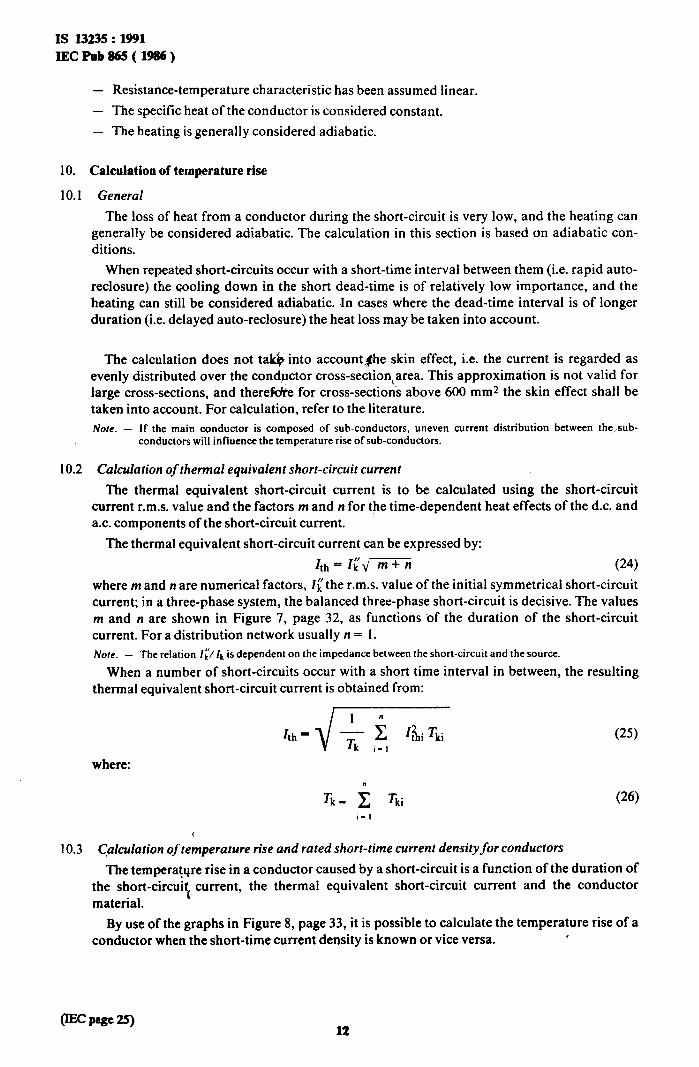
- Resistance-temperature characteristic has been assumed linear.
- The specific heat of the conductor is considered constant,
- The heating is generally considered adiabatic.
10. Calculation of temperature rise
10.1 General
The loss of heat from a conductor during the short-circuit is very low, and the heating can generally be considered adiabatic. The calculation in this section is based on adiabatic con- ditions.
When repeated short-circuits occur with a short-time interval between them (i.e. rapid auto- reclosure) the cooling down in the short dead-time is of relatively low importance, and the heating can still be considered adiabatic. In cases where the dead-time interval is of longer duration (i.e. delayed auto-reclosure) the heat loss may be taken into account.
The calculation does not taGinto account#he skin effect, i.e. the current is regarded as evenly distributed over the conductor cross-sectionarea. This approximation is not valid for large cross-sections, and there* for cross-sections above 600 mm2 the skin effect shall be taken into account. For calculation, refer to the literature. Note. - If the main conductor is composed of sub-conductors, uneven current distribution between the,sub-
conductors will influence the temperature rise of sub-conductors.
10.2 Calculation of thermal equivalent short-circuit current
The thermal equivalent short-circuit current is to be calculated using the short-circuit current r.m.s. value and the factors m and n for the time-dependent heat effects of the d.c. and a.c. components of the short-circuit current.
The thermal equivalent short-circuit current can be expressed by:
Ith = Ii,/- (24) where m and n are numerical factors, I[the r.m.s. value of the initial symmetrical short-circuit current; in a three-phase system, the balanced three-phase short-circuit is decisive. The values m and n are shown in Figure 7, page 32, as functions ‘of the duration of the short-circuit current. For a distribution network usually n = 1. Nore. - The relation I[/ /k is dependent on the impedance between the short-circuit and the source.
When a number of short-circuits occur with a short time interval in between, the resulting thermal equivalent short-circuit current is obtained from:
Ith==j/G (25)
where: n
Tk- c Tki (26)
I- I
10.3 Calculation oftemperature rise and rated short-time current densityfor conductors
The temperature rise in a conductor caused by a short-circuit is a function of the duration of the short-circuit current, the thermal equivalent short-circuit current and the conductor material.
By use of the graphs in Figure 8, page 33, it is possible to calculate the temperature rise of a conductor when the short-time current density is known or vice versa. .

Is 13235 : 1991 IEcPob86!5(I!X?6)
The highest recommended short-time temperature for different conductors is given in Table V. Note. - The maximum permitted temperature of the support has to be taken into account.
10.4 Calculation of the thermal short-circuit strength for different durations of the short-circuit current
Electrical equipment has suffkient thermal short-circuit strength as long as the following relations hold for the thermal equivalent short-circuit current Zth:
or Ith < Ithr for Tk < & CW
Ith < Ithr for Tk > Tkr Vb)
where Ztht is the rated short-time current and Tk, the rated short-time.
The thermal short-circuit strength fo&are conductogl is sufficient when the thermal equiv- alent short-circuit current density Su, satisfies the follovkng relation:
1 i,
(28)
with Tkr - 1 sand for all Tk.
The rated short-time current density &hr is shown in Figure 8, page 33.
i

IS 13235 : 1991
IECPub&i5(1986)
0.8
0.6
1 2 4 6 8 10
add - 017m
FIG. 1. - Factor kl, for effective conductor central distance 4.
4
Direction de la charge -E Loading direction
. t I
i
b)
Direction de la charge
Loading direction
FIG. 2. - Loading direction and bending axis with multiple conductor arrangements.
14
0 0.04 0.0% 0.12
m,l(n m; I)- &
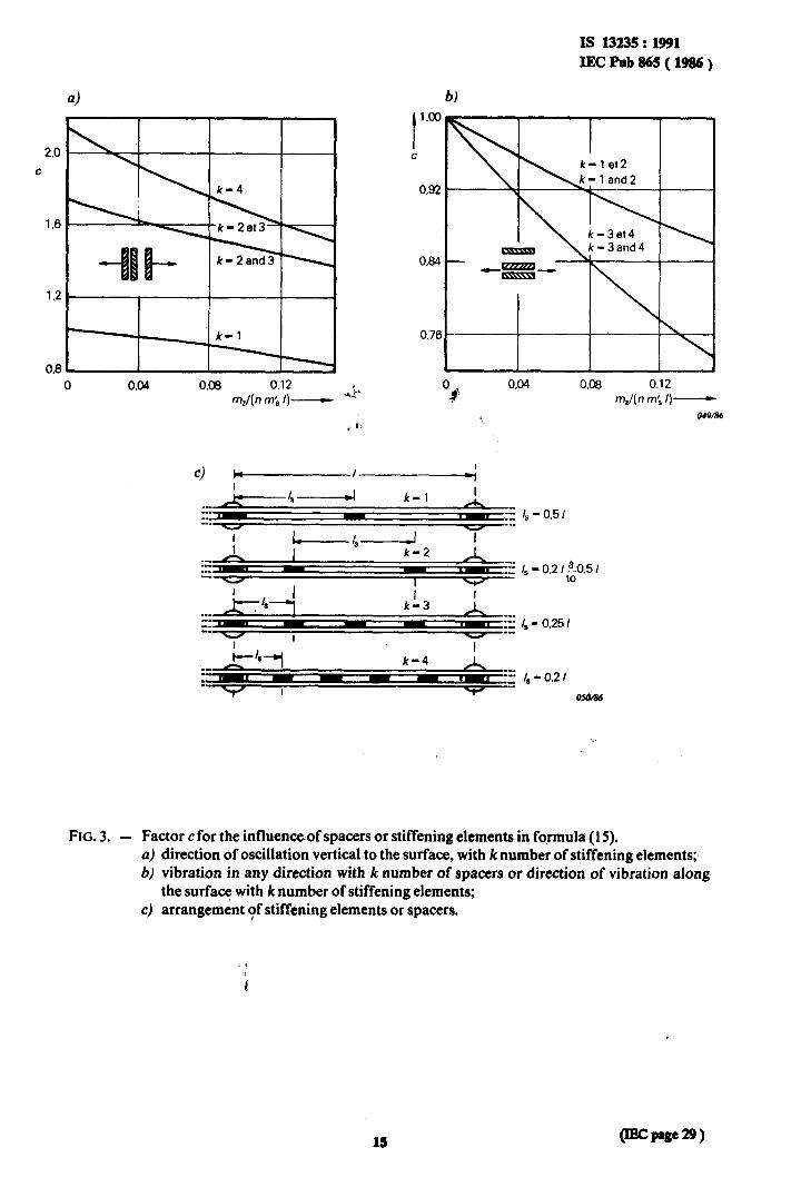
IS 13235 : 1991
IECpPbt365(1986)
b)
0.0% 0.12
m,l(n m; I)- ow86
FIG. 3. - Factor c for the influenceof spacers or stiffening elements in formula (15). a) direction of oscillation vertical to the surface, with k number of stiffening elements;, b) vibration in any direction with k number of spacers or direction of vibration along
the surface with k number of stiffening elements; c) arrangement of stiffening elements or spacers.
lb
IS 13235 : 1991
IECF’ab865(1986)
VF. VU. vi%
2.c
1 s
C t
,I
-
,
vu. VU!
/ c
L
L
se
i
1
fJf- OSlM6
FIG.~. - Factors VF, V, and V,, to be used with the two-phase and three-phase short-circuits; except arrangements with&“< 0.5 in which K < 1.6.
FIG. 5. - ‘iactor V, to be used with three-phase auto-reclosure.
(IEC page 30 y 16

IS 13235 : 1991
IECPub865(1986)
FIG.~. -
IO-' 2 46810 2 4 6 810' 2 4 68102 2 4 68103
Factor w for tensile force in flexible conductors. The connection between the factors I,V, c and cp is given by:
C= (l+cpVG* VI .P
2+(P+(Pw 1-v
( IEc pig= 31) 17

IS 13235 : 1991
IECPab865(1!M3fQ
6)
I 1 .o
0.8
n
0.6
0.4
0.2
1.8
m
1.4
0.6
0,i 0.2 .$ rk-
054/86
0.01 0.02 0.05 0.1 0.2 0.5 1 2 5 10 s rk-------
OJ.r/86
FIG. 7. - a) Factor m, heat dissipation due to d.c. component. b) Factor n, heat dissipation due to a.c. component.
(IEC page 32) 18

rs 13235: 1991 I;EcPub86!5(1986)
bi
S thr
u- I I 20 I
40 60
80 100 120 T
%- 056B4
FIG. 8. - Relation betwee: rated short-time current density (Tkr = I s) and conductor tem- perature. a) Full lines: Copper
Dotted lines: Flat product of unalloyed steel and steel cables. .
b) Numinium, ahminium alloy, aluminium conductor steel reint’orced (ACSR).

IS 13235 : 1991
IECPub865(1986)
TABLE I
Effective conductor central distance a, in metres, for rectangular section dimensions
c
I 0.05 0.06 Rectangularsections 0.20
- 0.080
0.16
- 0.067
0.12 0.10 0.08
b Ill -J ‘A
0.005 0.020 0.024 0.027 0.033 0.040
0.010 0.028 0.031 0.034 0.041 0.047
0.015 0.018 0.022 0.020 0.023 0.027
#'
- - 0.016 0.018
- 0.020
0.013 0.019
- 0.015
- 0.054
- 0.030
0.005 0.010
- 0.037
- 0.043
- 0.031
Q.017
.cs+
I h - 0.014
d
fh 1 -JLd
0.005 0.010
- 0.022
- 0.026
( IEC page 35) 20
IS 13235 : 1991
IECPub865(19m)
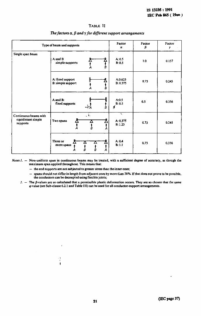
TABLE II
Thefactors a. j? andy for different support arrangements
Type of beam and supports Factor Factor Factor
.a B Y
Single span beam
Continuous beams with equidistant simple supports
AandB simple supports
f
A: 0.5 B: 0.5
1.0 0.157
A B
A: fixed support B: simple support
0.73 0.245
AandB: fixed supports
Two spans 0.73 0.245
Three or more spans
0.73 0.356
Nom I. - Non-uniform span in continuous beams may be treated, with a sufftcient degree of accuracy, as though the maximum span applied throughout. This means that: - the end supports are not subjected to greater stress than the inner ones;
- spans should not differ in length from adjacent ones by more than 20%. If that does not prove to be possible, the conductors can be decoupled using flexible joints;
2. - The @alues are so calculated that a permissible plastic deformation occurs. They are so chosen that the same q-value (see Sub-clause 6.2. I and Table 111) can be used for all conductor-support arrangements.
21 (II= PW 37)
4
2.00
1.70
d (;- - 0.05). 1.34
( “m 0.075). 1.37
i - O.loO), 1.40 - 0.12s). I.44
I - 0.160). 1.48 - 0.200). 1.5 I
E
-L 1.83
1 d.+ I.50
I fl&Z..
I.19
El
-L
A,
t
I.13
L
t 1
lsl3235:1B1 IECl’ob&S(l986)~
TABLE III
Acceptable q-values for diflerent cross-sections
i

Is 13235 : 1991 IECPnb&i5(1986)
TABLE IV
Section moduli Z in cubic centimetres of main conductors with two and more stiffening element:
mxm
0.05x0.01 0.06x0.01 0.08x0.01 0.10x0.01 0.12x0.01
I
9.9 11.9 15.8 19.8 23.8
Fm{ &, 6.9 8.7 A.4 13.9 d t7.3 20.8
I 1..
31.7 39.6
__
TABLE V
Recommended highest conductor temperatures in the case of short circuit
Type of conductors I Max. recommended conductor temperature in case of short-circuit I
Mechanical loaded bare conductors, solid or stranded, Al or Cu
Aluminium alloy
Loaded steel
Unloaded steel
Cables and conductors, paper and plastics insulated
2WC
l7OC
250°C
3OOYz
l
* Recommended temperatures are dealt with by 1 EC Technical Committee NO. 20: Electric Cables, and Sub-Com- mittee 20A: High-voltage Cables.

IS 13235 : 1991
IECPub865(1986)
APPENDIX
EXAMPLES OF CALCULATION OF THE EFFECTS OF SHORT-CIRCUIT CURRENTS
Example 1. Mechanical effects on single rigid conductors Basis for the calculations in this example is a three-phase system with one bus-bar per phase. The
bus-bars are mounted on edge. The cross-section is 60 x 10 mm2 and the material is an Al-Mg-Si- alloy.
The following data are given:
1 - l.Om E - 70 Ooo N/mm2 a - 0.2 m J = 0.5 cm4
$3 - 30kA z - l.Ocm3 m’ - 1.62 kg/m & RPo.2 - 12t$N/mmz up to 180 N/mm2
Number of spans: 3 * g. “‘.
The natural frequency of the bus-bars is:
fc The ratio 7
is 1.05. This gives the following values to the factors VF; V, and Vr:
“-6 $0.2 ‘. VF -1.8 if&‘vr<--
%I (with the upper value of Q.2)
v, - 1.0
v, - 1.0
Maximum force on the central bus-bar is:
& 0.2 0.87 2 1 1.0
- l l iP3 l - - 0.2 l 0.87 9 302 l a o2 .
- 783 N
Maximum bending stress is:
- 71.5 N/mm2
Maximum bending force on the supports is: &- VF &a&, = 1.8 . 1.0. 1.1 . 783 - 155ON
The bus-bars are assumed to withstand the short-circuit force if:
ad < q b.2 (with the lower value of Q.i,
For!a rectangular cross-section q - 1.5. This gives: . 6 a, < 1.5 l 120 - 180 N/mm2
Conclusions: ;
The bus-bars will withstand the short-circuit force. The supports have to withstand a dynamic bending force of 1550 N.
( m pais 43) 24
Is13235:1!m lECPkb86!J(l986)
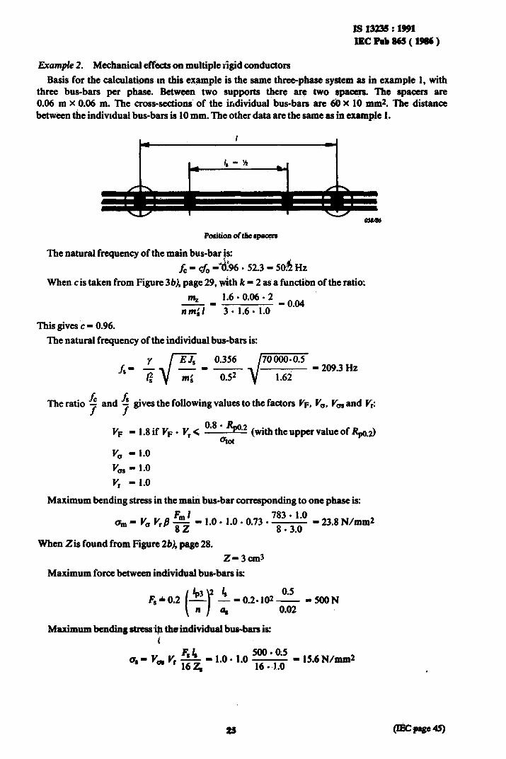
Example 2. Mechanical efkts on multiple rigid conductors
Basis for the calculations m this example is the same three-phase system as in example 1, with three bus-bars per phase. Between two supports t@ere &re two spacers, The spacers are 0.06 m X 0.06 m. The cross-sections of the irAvidual bus-bars are & X 10 mm& The distance betwken the indivtdual bus-bars is 10 mm. The other data are the same as in example 1.
The natural frequency of the main bus-bar is:
fc - cfo -41% -52.3 - 506 Hz
When c is taken from Figure 3b), page 29, wkh k - 2 as a functibn of the ratio:
m, 1.6 l 0.06. 2 _ oo4
- - 301.6. 1.0 nmil *
This gives c - 0.96.
The natural frequency of the individual bus-bars is:
fc A The ratio - and T f
gives the following values to the factors VF, V,. V, and V,:
v, - 1.8if yF* &< 0.8 (with the upper value of I+) 2) aiot
.
v, - 1.0
Km - 1.0
v, - 1.0
Maximum bending stress in the main bus-bar corresponding to one phase is:
am- V, 4Dl
V,B- * l
82 1.0 1.0 9 0.73
783 . 1.0 l -
8 . 3.0 23.8 N/mm2
When Zis found from Figure Zb), page 28.
z-3cm3
Maximum force between individual bus-blirs is:
-()[email protected] -500N 0.02
Maximum bending stress* theindividual bus-bars is: i
FIlr - - 1.0. 1.0 4’ ‘,v, 16z, ;; ‘pa’ - 15.6N/mm2 l .
25
Is 13236 : 1991 lECPub86S(lp86)
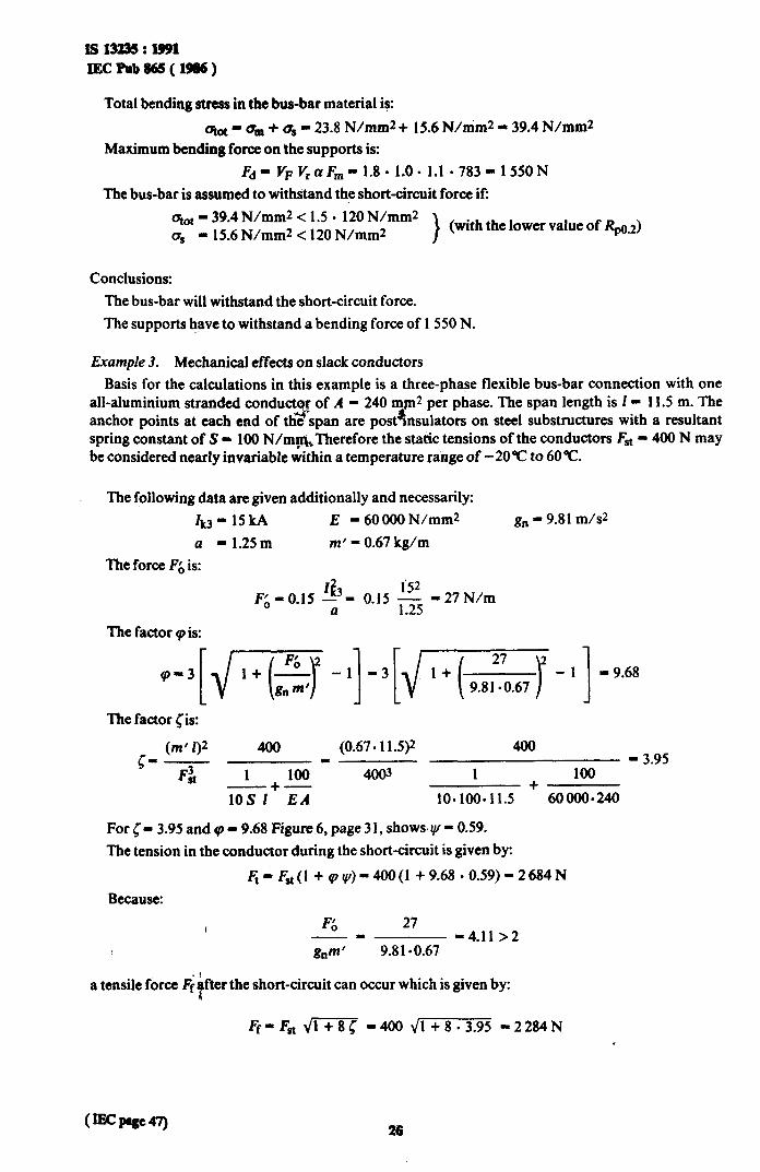
Total bending stress in the bus-bar material is:
atot - q,, + us - 23.8 N/mm2 + 15.6 N/mm2 - 39.4 N/mm2 Maximum bending force on the supports is:
Fd- VF Y,o& - 1.8. 1.0. 1.1 l 783 - 1550N The bus-bar is assumed to withstand the short-circuit force if:
qot - 39.4 N/mm2 < 1.5 - 120 N/mm2 a, - 15.6 N/mm2 < 120 N/mm2 >
(with the lower value of Rpo.2)
Conclusions: The bus-bar will withstand the short-circuit force. The supports have to withstand a bending force of 1550 N.
Example 3. Mechanical effects on slack conductors Basis for the calculations in this example is a three-phase flexible bus-bar connection with one
all-aluminium stranded conduct r of A &
- 240 mp2 per phase. The span length is I - 11.5 m. The anchor points at each end of the span are pos&ulators on steel substructures with a resultant spring constant of S - 100 N/m&Therefore the static tensions of the conductors Fst - 400 N may be considered nearly invariable within a temperature range of -20°C to 60°C.
The following data are given additionally and necessarily: Ikj- 15kA E = 60 000 N/mm* gn - 9.81 m/s2 a - 1.25m m’ = 0.67 kg/m
The force Fr, is:
F&-O.15 s3= 0.15 g -27N/m a .
The factor 9 is:
.-3[j/w -I]-3[j,/m-1] -9.68
The factor Cis:
c- (m’I)Z 400 (0.67.11.5)* 400 - I - 3.95
F: 1 100 4003 1 100
10s 1+EA +
10*100*11.5 60000*240
For c - 3.95 and (p - 9.68 Figure.6, page 3 1, shows y/ - 0.59. The tension in the conductor during the short-circuit is given by:
h-&(1 +Q,@-400(1 +9.68.0.59)-2684N Because:
, 6 27 -- -4.11 >2 gnm’ 9.8 100.67
a tensile force F;$ter the short-circuit can occur which is given by:
Ff-Fst m -400 &+8-3.95 -2284N
Is 13236: 1991 IltCRib865(~~
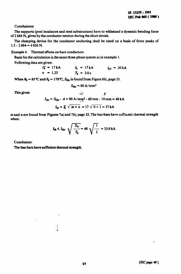
Conclusions:
The supports (post insulators and steel substructure) have to withstand a dynamic bending force of 2 684 N, given by the conductor tension during the short circuit.
The clamping device for the conductor anchoring shall be rated on a basis of force peaks of 1.5.2684-4026N.
Example 4. Thermal effects on bare conductors
Basis for the calculation is the same three-phase system as in example 1.
Following data are given:. Ig - 17kA zk - 17kA ip3 - 30kA K * 1.25 =k - 2.0s
Whent&-65Tand0, - 17OT, s;h, is found from Figure 86), page 33.
Stht - 80 A/mm*
This gives: $7 ?2’ I:h~gStht’A’80A/mlp*060mm. lOmm,-48kA
I
m and n are found from Figures 7~) and 76), page 32. The bus-bars have sufitient thermal strength when:
Conclusion:
The bus-bars have sufftcient thermal strength.
i
27

Bureau of Indian Standards
BIS is a statutory institution established under the Bureau oflndian Standards Act, 1986 to promote harmonious development of the activities of standardization, marking and quality certification of goods and attending to connected matters in the country.
Copyright
BIS has the copyright of all its publications. No part of these publications may be reproduced in any form without the prior permission in writing of BIS. This does not preclude the free use, in the course of implementing the standard, of necessary details, such as symbols and sizes, type or grade designations. Enquiries relating to copyright be addressed to the Director (Publications), BIS.
Review of Indian Standards
Amendments are issued to standards as the need arises on the basis of comments. Standards are also reviewed periodically; a standard along with amendments is reaffirmed when such review indicates that no changes are needed; if the review indicates that changes are needed, it is taken up for revision. Users of Indian Standards should ascertain that they are in possession of the latest amendments or edition by referring to the latest issue of ‘CIS Handbook’ and ‘Standards : Monthly Additions’.
This Indian Standard has been developed f% Dot : No. ET$: 20 ( 2824 )
Amendments Issued Since Publication
Amend No. Date of Issue Text Affected
Headquarters:
BUREAU OF INDIAN STANDARDS
Manak Bhavan, 9 Bahadur Shah Zafar Marg, New Delhi 110002 Telephones : 323 01 31, 323 94 02, 323 33 75
Telegrams: Manaksanstha ( Common to
all offices )
Regional Offices: Telephone
Central : Manak Bhavan, 9 Bahadur Shah Zafar Marg 323 76 17 NEW !‘ELHI 110002 323 3841
Eastern : l/14 C. I. T. Scheme VII M, V. I. P. Road, Maniktola CALCUTTA 700054
Northern : SC0 335-336, Sector 34-A, CHANDIGARH 160022
Southern : C. I. T. Campus! IV Cross Road, CHENNAI 600113
337 84 99, 337 85 61 337 86 26,337 86 62
1 60 38 43 60 20 25
2350216,2350442 235 15 19,235 23 15
Western : Manakalaya, E9!MIDC, Marol, Andheri (East) MUMBAI 4OOOq3
8329295,8327858 8327891,8327892
Branches : AHMADABAD. BANGALORE. BHOPAL. BHUBANESHWAR. COIMBATORE. FARIDABAD. GHAZIABAD. GUWAHATI. HYDERABAD. JAIPUR. KANPUR. LUCKNOW. NAGPUR. PATNA. PUNE. THIRUVANANTHAPURAM.
Printed at New India Printing Press, Khuqs, India