is 3651-2 (1985): vernier calipers, part 2: vernier ... · accordingly the standard was split and...
TRANSCRIPT

Disclosure to Promote the Right To Information
Whereas the Parliament of India has set out to provide a practical regime of right to information for citizens to secure access to information under the control of public authorities, in order to promote transparency and accountability in the working of every public authority, and whereas the attached publication of the Bureau of Indian Standards is of particular interest to the public, particularly disadvantaged communities and those engaged in the pursuit of education and knowledge, the attached public safety standard is made available to promote the timely dissemination of this information in an accurate manner to the public.
इंटरनेट मानक
“!ान $ एक न' भारत का +नम-ण”Satyanarayan Gangaram Pitroda
“Invent a New India Using Knowledge”
“प0रा1 को छोड न' 5 तरफ”Jawaharlal Nehru
“Step Out From the Old to the New”
“जान1 का अ+धकार, जी1 का अ+धकार”Mazdoor Kisan Shakti Sangathan
“The Right to Information, The Right to Live”
“!ान एक ऐसा खजाना > जो कभी च0राया नहB जा सकता है”Bhartṛhari—Nītiśatakam
“Knowledge is such a treasure which cannot be stolen”
“Invent a New India Using Knowledge”
है”ह”ह
IS 3651-2 (1985): Vernier Calipers, Part 2: VernierCalipers with Least Count 0.02 mm [PGD 25: EngineeringMetrology]

UDC 531’714’8 IS:3651
. . ‘c:
P
Part
Indian Standard
SPECIFICATION FOR VERNIER CALLIPERS
PART 2 VERNIER CALLIPERS WITH LEAST COUNT 0’02mm
1. Scope -- Covers the essential dimensional, functional and auality characteristics and methods for testing the accuracy of vernier callipers with least count 0’02 mm with a maximum measuring range of 500 mm.
111 Vernier callipers with least count of 0’1 and 0’05 mm are covered in IS : 3651 (Part 1) - 1982 ‘Vernier callipers : Part 1 Vernier callipers with least count 0’1 mm and 0‘05 mm ( second revision )‘.
Note-These vernier callipers are also known as l/50 mm vernier callipers.
2. Types
2.1 Type A - With jaws on both sides for external and internal measurements. They have a blade for depth measurement for 0 to 150 mm measuring range only (see Fig. 1 ).
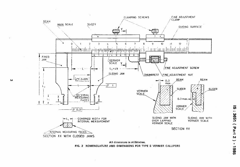
2.2 Type B - With jaws on one side for external and internal measurements (see Fig. 2).
Note - Both types of vernier callipers should be provided with fine adjustment mechanism.
3. Nomenclature - Shall be as given in Fig. 1 and Fig. 2.
4. Definitions - For the purpose of this specification the following definitions shall apply.
4.1 Error of Measurement - The algebraic difference between the measured size and the true size.
4.2 Measuring Range - The maximum distance that the jaws may be separated without the vernier scale projecting beyond the main scale.
4.3 Measuring Uncertainty - The error margin corresponding to the inherent errors of measurement of a vernier calliper. It is defined as being equal to f2s, that is, for a normal distribution of the readings on the instrument, about 95 percent of readings will not deviate from the mean size (true value) by more than twice the standard deviation S.
5. Material - The main parts of vernier callipers such as beam, sliding jaw and depth measuring blade shall be manufactured from either carbon steel or stainless steel.
6. Hardness - The hardness shall be:
a) for the beam, 350 HV, Min
b) for the measuring faces of the jaws
-made of carbon steel, 700 HV, Min
-made of stainless steel 550 HV, Min
c) for the measuring face of depth measuring blade 475 HV, Min
7. Dimensions - Shall be as given in Table 1.
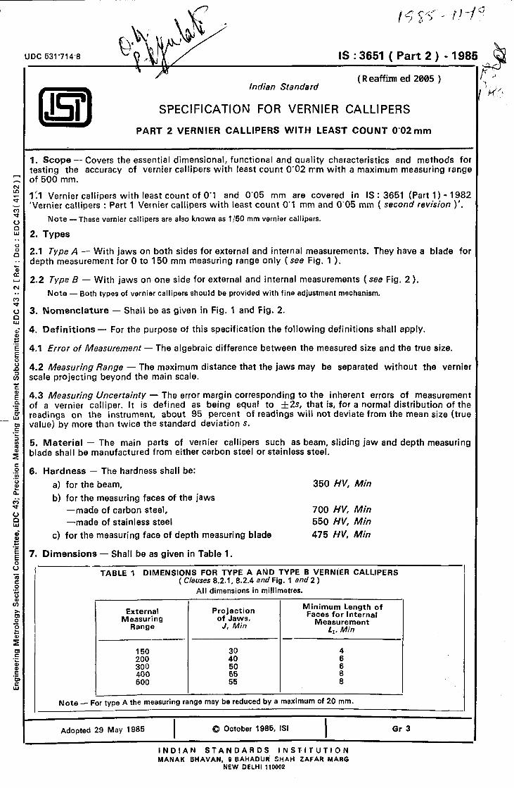
TABLE 1 DIMENSIONS FOR TYPE A AND TYPE B VERNIER CALLIPERS ( Clauses 8.2.1, 8.2.4 and Fig. 1 and 2 )
All dimensions in millimetres.
External Me&sulugrkng
Projection of Jaws.
J, Min
Minimum Length of Faces for Internal
Measurement L1. Min
-
150 4 200 4300 300 50 x 400 500 5655 :
Note - For type A the measuring range may be reduced by a maximum of 20 mm.
Adopted 29 May 1985 I
(Q October 1985, ISI I
INDIAN STANDARDS INSTITUTION MANAK BHAVAN, 9 BAHADUd SHAH ZAFAR MARG
NEW DELHI 110002
Gr 3
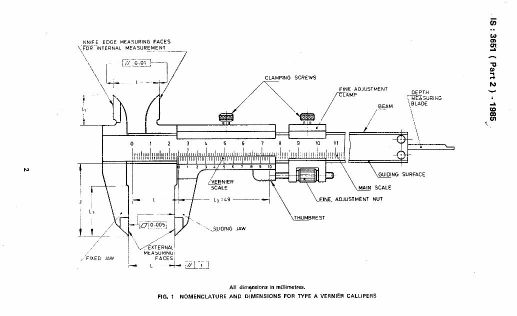
KNIFE EDGE MEASURING FACES _ _. \F~R INTERNAL MEASUREMENT -- .- I_.
\ 7
PING SCREWS
I
\
b ADJUSTMENT NUT
All dimynsions in millimetres.
FIG. 1 NOMENCLATURE AND DIMENSIONS FOR TYPE A VERNIER CALLIPERS
.
IS:3651 (Part2) -1985
8. General Requirements
8.1 Beam -The beam shall be long enough for the sliding jaw assembly not to overhang when measuring at the maximum measuring range.
8.2 Jaws
8.2.1 The projections J of the two jaws shall be equal. The minimum projection of the jaws J shall be as given in Table 1. The maximum projection of the jaws J shall be equal to one-third of the measuring range, but with a maximum of 200 mm.
8.2.2 The sliding jaw shall be a good sliding fit along the beam in order to permit fine adjustments to be made. The slider shall be provided with a suitable clamp so that it may be effectively clamped to the beam without altering the position of the measuring faces by more than 1Opm.
8.2.3 For the minimum length of the faces for external measurement, La Min shall be one-half the projection of the jaws.
8.2.4 The minimum length of internal measuring jaws Ll shall be as given in Table 1.
8.2.5 The nominal combined width Ld, of the jaws for internal measurement for Type B verniers shall be 5, 10 or 20 mm (see Fig. 2). In this type of verniers the faces for internal measurement shall be of cylindrical form with a radius not exceeding one-half of their combined width.
8.2.6 The fit of the sliding jaw on the beam shall permit the various tolerances on measuring accuracy to be complied with under all conditions of normal use.
8.3 Depth heasuring Device - The vernier callipers may be provided with a depth measuring blade which is connected to the sliding jaw and allows the measurement of depths with reference to the end of the face of the beam (see Fig. 1). The accuracy of measurement of this depth measurement shall be medium grade of IS : 2102 (Part l)-1980 General tolerances for linear and angular dimensions ( second revision 1.
8.4 Scales
8.4.1 The beam shall be graduated in millimetres and figured in millimetres or centimetres. The length of the scale shall be at least equal to the measuring range of the callipers plus the length of the vernier.
8.4.2 The length of the vernier scale LB shall be 49 mm ( see Fig. 1 and 2 ).
8.4.3 The scale lines of both the beam and the vernier shall be straight, sharp-edged, and perpen- dicular to the edge of the beam and their thickness shall be between 0’08 and 0’18 mm.
Note -The beam and the sliding jaw may be provided with two scales, one for external measurement, the other for internal measurement and with direct reading for each scale.
8.5 Graduations
8.5.1 The numbering on the beam shall be such that the scale is easy to read.
8.5.2 The distance between the graduated face of the beam and the edge of the graduated face of the vernier shall not exceed 0’3 mm (see Fig 2).
8.5.3 To facilitate reading, the surfaces of the beam and the vernier may be given a matt finish and the graduation lines filled with black pigment.
9. Accuracy
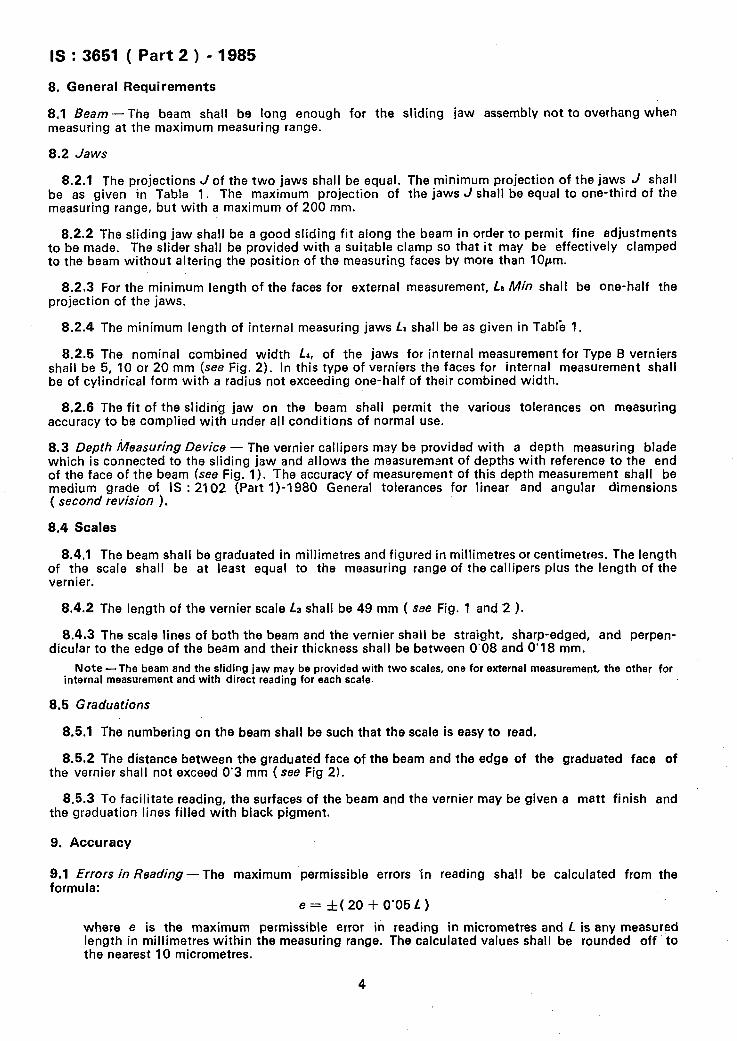
9.1 Errors in Reading-The maximum permissible errors In reading shall be calculated from the formula:
e= &(20+0’05L)
where e is the maximum permissible error in reading in micrometres and L is any measured length in millimetres within the measuring range. The calculated values shall be rounded off to the nearest 10 micrometres.
4
IS:3651(Part2)-1985
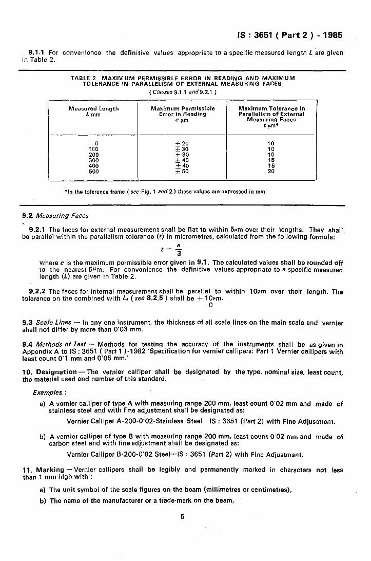
9.1.1 For convenience the definitive values appropriate to a specific measured length L are given in Table 2.
TABLE 2 MAXIMUM PERMISSIBLE ERROR IN READING AND MAXlMUM TOLERANCE IN PARALLELISM OF EXTERNAL MEASURING FACES,
( Clauses 9.1.1 and9.2.1 )
Measured Length L mm
Maximum Permissible Error in Reading
e pm
:o”
:; 40 50
-
Maximum Tolerance in Parallelism of External
Measuring Faces t pm*
10 10
1:
:o”
*In the tolerance frame ( see Fig. 1 and 2 ) these values are expressed in mm.
9.2 Measuring Faces
’ 9.2.1 The faces for external measurement shall be flat to within 5pm over their lengths. They shall be paralUel within the parallelism tolerance (t) in micrometres, calculated from the following formula:
where e is the maximum permissible error given in 9.1. The calculated values shall be rounded off to the nearest 5pm. For convenience the definitive values appropriate to a specific measured length (L) are given in Table 2.
9.2.2 The faces for internal measurement shall be parallel to within 10lrm over their length. The tolerance on the combined with La (see 8.2.5 ) shall be + 1 Olrm.
0
9.3 Scale Lines - In any one instrument, the thickness of all scale lines on the main scale and vernier shall not differ by more than 0’03 mm.
9.4 Methods of Test - Methods for testing the accuracy of the instruments shall be as given in Appendix A to IS : 3651 ( Part 1 >-I 982 ‘Specification for vernier callipers: Part 1 Vernier callipers with least count 0’1 mm and 0’05 mm.’
10. Designation -The vernier calliper shall be designated by the type, nominal size, least count, the material used and number of this standard.
Examples :
a) A vernier calliper of type A with measuring range 200 mm, least count 0’02 mm and made of stainless steel and with fine adjustment shall be designated as:
Vernier Calliper A-200-0’02Stainless Steel-IS : 3651 (Part 2) with Fine Adjustment.
b) A vernier calliper of type 6 with measuring range 200 mm, least count 0’02 mm and made of carbon steel and with fine adjustment shall be designated as:
Vernier Calliper B-200-0’02 Steel-IS : 3651 (Part 2) with Fine Adjustment.
11. Marking -Vernier callipers shall be legibly and permanently marked in characters not less than 1 mm high with : .
a) The unit symbol of the scale figures on the beam (millimetres or centimetres),
b) The name of the manufacturer or a trade-mark on the beam,
5
IS : 3651 ( Part 2 ) - 1985
c) The indication 0’02 mm or 1150 mm on the vernier,
d) In case of type B ve@iers the combined width of Jaws La for internal measurement shall be legibly marked on the jaws.
11 .l /St Certification Marking - Details available with the Indian Standards Institution.
12. Packing - Each vernier shall be coated with suitable anti-corrosive coating and shall be wrapped in a m&sture proof paper or any other suitable wrapping material. The callipers shall then be supplied in a‘ suitable protective case.
EXPLANATORY NOTE
IS : 3651 originally published in 1966 was subsequently revised in 1974. The committee responsible for preparation of this standard again decided to revise it in line with IS0 standards. Accordingly the standard was split and IS ; 3651 (Part 1 F-1982 ‘Specification for vernier callipers : Part 1 Vernier callipers with least count 0’1 mm and 0’05 mm’ was published in 1982 based on IS0 3599-1976 ‘Vernier callipers reading to 0’1 mm and 0’05 mm’ issued by the International Organization for Standardization (ISO).
This standard (Part 2) has now been brought out and in its preparation considerable assistance has been derived from IS0 6906-1984’ Vernier callipers reading to 0’02 mm’ issued by ISO.
In respect of foot note given in Table 1 on reduction of measuring range the reference has been drawn from manufacturers catalogues.
6
Printed at Printradr. New Delhi, India