is-95 cdma - university of pittsburghdtipper/2700/2700_slides9_2.pdfis-95 (cdmaone) david tipper...
TRANSCRIPT

1
ISIS--95 (95 (cdmaonecdmaone))
David TipperAssociate ProfessorAssociate Professor
Graduate Telecommunications and Networking Program
University of PittsburghSlides 9
http://www.sis.pitt.edu/~dtipper/2700.htmlhttp://www.sis.pitt.edu/~dtipper/2700.html
TELCOM 2700 2
IS-95 CDMA• IS-95 (cdmaone) 2G digital cellular standard• Motivation
– Intended as a new system (greenfield) or replacement for AMPS (not an upgrade)
– Increase system capacity – Add new features/services
• History: – 1990 Qualcomm proposed a code division multiple access
(CDMA) digital cellular system claimed to increase capacity by factor 20 or more
– Started debate about how CDMA should be implemented and the advantages vs. TDMA (religious tones to debate)
– 1992 TIA started study of spread spectrum cellular
2
TELCOM 2700 3
IS-95 CDMA (cont)• Several alternative CDMA proposals floated – large
debate in the CTIA – came down to Interdigital vs. Qualcomm – Qualcomm proposal won
• 1993 TIA IS-95 code division multiple access (CDMA) standards completed– 1995 IS-95A enhanced revision – ANSI J-STD-008 (IS-95b) is standard upbanded to
1900 MHz PCS band– 1996 Commercial deployment in US (Sprint PCS)– Most popular system in U.S. and Korea– 1997 IS-95 name changed to cdmaone
• IS-95 evolves to cdma 2000 in 2.5 and 3G
TELCOM 2700 4
IS-95 System Features • Digital Voice
– QCELP fixed rate 14.4Kbps coder– variable rate QCELP coder: 9.6, 4.8, 2.4, 1.2 Kbps
• Use of voice activation to reduce interference• As data rate reduces, the transmitter can reduce the power to
achieve the same error rates• Dual Mode (AMPS/CDMA), Dual Band (900, 1900 MHz bands)• Low power handsets (sleep mode supported)• Soft Handoff possible• Digital Data services (text, fax, circuit switched data)• Advanced Telephony Features (call waiting, voice mail, etc.)• Security: CDMA signal + CAVE encryption • Air Interface Standard Only

3
TELCOM 2700 5
IS-95 System Features • Code Division Multiple Access/FDMA/FDD• Traffic Channel
– Pair of 1.25 MHz radio channels (up/downlink)– Several users share a radio channel separated by a code not a
timeslot or frequency! – Receiver performs a time correlation operation to detect only
desired codeword– All other codewords appear as noise due to decorrelation– Receiver needs to know only codeword and frequency used by
transmitter– Adjust power often to prevent near –far problem
• Universal frequency reuse (frequency reuse cluster size K =1) – Simple planning – large capacity increase
TELCOM 2700 6
CB D
FG E
A
CB D
FG E
A
CB D
FG E
A
Universal Frequency Reuse
AA A
AA A
A
AA A
AA A
A
AA A
AA A
A
FrequencyReuse Factor = 7 for AMPS
FrequencyReuse Factor = 7 for AMPS
CCBB DD
EEAA
FFGG
CDMA UniversalFrequency ReuseCDMA UniversalFrequency Reuse
Frequency Reuse Factor = 4 or 3 for GSM systems

4
TELCOM 2700 16
IS-95 CDMA - Radio Aspects • IS-95 is an air interface standard only• System use FDD/FDMA/CDMA • FDD => Uplink and Downlink channels separated
according to Cellular band or PCS band regulatory requirements
• FDMA – breaks up licensed spectrum into 1.25 MHz channels
• CDMA – multiple users share a 1.25 MHz channel by using orthogonal spreading codes (Walsh codes)
• IS-95a standard designed for AMPS cellular band – Each cellular provider is allocated 25 MHz spectrum
=> ten 1.25-MHz CDMA duplex channels if A AMPS Band provider, 9 if B band provider
TELCOM 2700 17
Physical channels• A CDMA system has 1.25 MHz wideband carriers
– Carrier bandwidth in AMPS is 30 kHz– Carrier bandwidth in GSM is 200 kHz– Carrier bandwidth in IS-95 is 1.23 MHz 1.25MHz with guard
band• One CDMA carrier can contain 41 AMPS channels of spectrum
• In Cellular Band IS-95 carrier frequencies are denoted in terms of the AMPS channel numbers
283 303 304 312 313
… … … …262 263253 254
41 AMPS channels

5
TELCOM 2700 18
Interference between CDMA and AMPS/TDMA systems
• The recommended guard band between the CDMA carrier band edge and an AMPS or TDMA carrier is 270 KHz => 9 AMPS channels of 30 kHz
• To set up one CDMA channel, 59 AMPS channels have to be cleared (1.77 MHz)
• To set up two CDMA channels, only 100 AMPS channels have to be cleared (3 MHz)
283 303 304 312 313
… … … …262 263253 254
41 AMPS channels 9 guard channels
9 guard channels
TELCOM 2700 19
IS-95 Radio Ascpects
With 20 ms spanInterleaving
Convolutional codingConstraint length = 9
Viterbi decoding
Coding
1.23 MHz -> 1.25 MHz with guard band
Filtered bandwidth
9.6 kbpsNominal data rate (Rate Set 1)
1.2288 McpsChannel/Chip rate
Quadrature phase shift keying or variations
Modulation

6
TELCOM 2700 20
IS-95 Radio Aspects• IS-95 uses several techniques adapted from military
– Direct Sequence Spread Spectrum (DSSS)• Narrowband signal is multiplied by very large bandwidth signal
(spreading signal)• Spreading signal is pseudonoise code sequence with chip rate much
greater than data rate of message• DSSS provides resistance to narrowband interference, inter-symbol
interference and low power operation– Code Division Multiple Access
• All users, each with own codeword approximately orthogonal to all other codewords, can transmit simultaneously with same carrier frequency
• Receiver performs a time correlation operation to detect only desired codeword
– Rake Receiver• Multiple parallel receivers used to combat multi-path interference and
inter-symbol interference
TELCOM 2700 22
IS-95 Multipath Combining
• Multipath: reflection, diffraction, and dispersion of the signal energy caused by natural obstacles such as buildings or hills, or multiple copies of signals sent intentionally (e.g., soft handoff)
• Rake receiver used to combine different path components: each path is despread separately by “fingers” of the Rake receiver and then combined
• Possible due to “low auto-correlation” of spreading code

7
TELCOM 2700 23
RadioDemodulator
Correlator
Correlator
Correlator
binarydecision
Digital carrier
Digital carrier
Digital carrier
Receivedsignal
Radio-frequencycarrier
RAKE receiver
Rake Receiver
RAKE receiver combines the multipath signals constructively
TELCOM 2700 24
Multipath and the RAKE Receiver

8
TELCOM 2700 25
Processing of multipaths using the Rake Receiver
x In te g ra te a n dd u m p (T b)
H o ld u n tilT b+ pNΔ
T b
x In te g ra te a n dd u m p (T b)
H o ld u n tilT b+ pNΔ
x In te g ra te a n dd u m p (T b)
H o ld u n tilT b+ pNΔ
x In te g ra te a n dd u m p (T b)
∑
.
.
.
2Δ+bT
3Δ+bT
)(1 tc
)( 21 Δ−tc
)( 31 Δ−tc
N pbT Δ+)(1 N ptc Δ−
x
.
.
.
P a th 1
P a th 2
P a th N p
D e c id e
TELCOM 2700 28
Codes used in IS-95 systems
• Walsh codes– They are the “orthogonal codes” used to create “logical
channels” on the up/downlink (at the same time and within the same frequency band)
• PN (pseudo-noise) codes– They are used to distinguish between transmissions from
different cells and are generated using “linear feedback shift registers”
– Basically a pseudo-random number generator– They have excellent autocorrelation properties– Two short PN codes and a long PN code are used in IS-95
that have periods of 215 – 1 and 242 – 1• Convolutional codes for error correction• Block codes with interleaving and error correction

9
TELCOM 2700 29
Delay applied to random number sequence at a base station
9 Pseudo-noise code offset PN_OFFSET
Location Area defined by operating company
12Registration ZoneReg_Zone
Service providers ID 16Network identifierNID
Assigned by regulators to a geographical service area
15System identifierSID
Assigned by manufacturer to a mobile station
32Electronic serial number
ESN
Directory number assigned by operating company to a subscriber
34Mobile IdentifierMIN
DescriptionSize (bits)NameNotation
Sample IS-95 System Identifiers
TELCOM 2700 30
IS-95 Logical Channels• CDMA systems define multiple channels per frequency channel• Pilot channel
– Provides a reference to all signals (beacon)• Sync channel
– Used for obtaining timing information• Paging channel
– Used to “page” the mobile terminal when there is an incoming call• Traffic channel
– Carries actual voice or data traffic : fundamental code channel• Up to seven supplemental code channels
ForwardPilotSyncPaging Variable-Bit-Rate
User Info.Power ControlSignaling Messages
Reverse Access
Traffic
Traffic
Variable-Bit-Rate User Info.Signaling Messages

10
TELCOM 2700 31
IS-95 CDMA Channels
• Types of channels
Forward channelsPilotSynchronizationPagingTrafficReverse channels
Access
Traffic
Channels
System mon.Sync.SignalingVoice/data
Signaling
Voice/data
Application
NA120096009600/14,400
4800
9600/14,400
bits/s
Walsh code 0Walsh code 32Walsh codes 1-7Walsh 8-31,33-63
Access channellong code maskWalsh code in modulation+ Access channellong code mask
Spreadingcode
TELCOM 2700 32
Basic Spreading Procedure on the Forward Channel in IS-95
• Symbols are generated at different rates• For the spread signal to be at 1.2288 Mcps, the incoming stream
must be at: 1.2288 x 10⁶/64 = 19.2 kbps• What happens if the incoming stream is at a lower rate?
– Example: Incoming stream is at 4.8 kbps– Number of chips per bit = 1.2288 x 10⁶/4.8 x 103 = 256 – End result is greater spreading
BasebandFilter
BasebandFilter
I PN at 1.2288 Mcps
Q PN at 1.2288 Mcps
1.2288 Mcps
Walsh Code
ChannelDependentSymbols

11
TELCOM 2700 33
One Forward CDMA Link, 1.25 MHz in the 824 – 849 MHz bands
Pilot Synch PCH 1
PCH 7
TCH 1
TCH8
TCH25
TCH55
W0 W32 W1 W7 W63
Fundamental Code Channel
Data
Mobile PowerControl
Subchannel
Fundamental Code Channel
Data
Mobile PowerControl
Subchannel
W8W16
IS-95 Forward (Downlink) Channel
TELCOM 2700 34
IS-95 CDMA Forward Channel Modulation
[Rapport Fig 10.14] CDMA forward channel modulation process
12
TELCOM 2700 35
To QPSK Modulator
BasebandFilter
BasebandFilter
I Pilot PN at 1.2288 Mcps
Q Pilot PN at 1.2288 Mcps
1.2288 Mcps
Walsh Code W0
All 0s
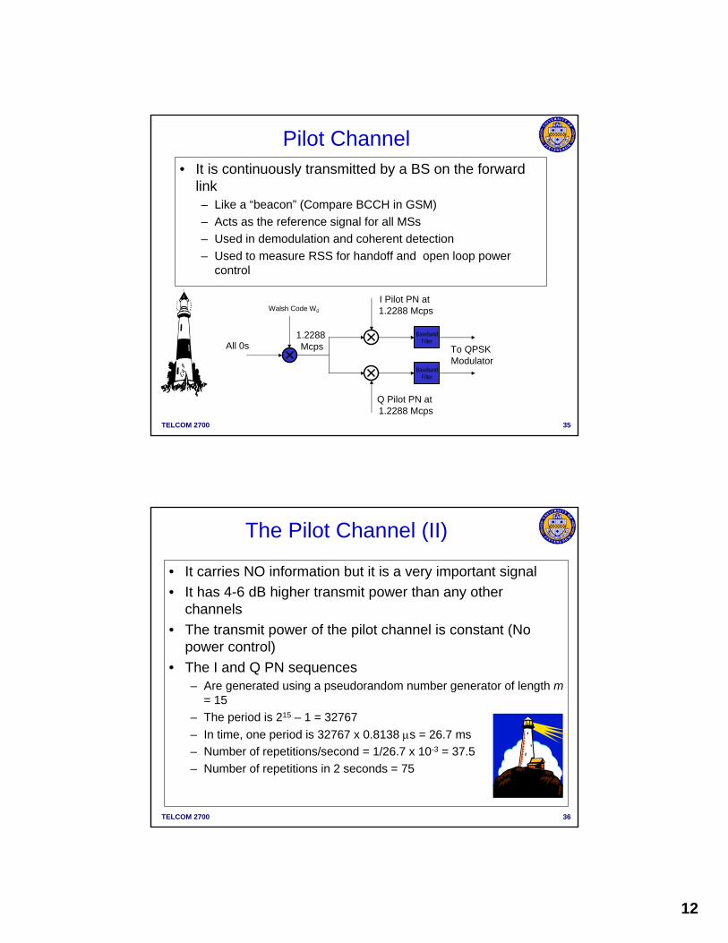
Pilot Channel• It is continuously transmitted by a BS on the forward
link– Like a “beacon” (Compare BCCH in GSM)– Acts as the reference signal for all MSs– Used in demodulation and coherent detection– Used to measure RSS for handoff and open loop power
control
TELCOM 2700 36
The Pilot Channel (II)
• It carries NO information but it is a very important signal• It has 4-6 dB higher transmit power than any other
channels• The transmit power of the pilot channel is constant (No
power control)• The I and Q PN sequences
– Are generated using a pseudorandom number generator of length m= 15
– The period is 215 – 1 = 32767– In time, one period is 32767 x 0.8138 μs = 26.7 ms– Number of repetitions/second = 1/26.7 x 10-3 = 37.5– Number of repetitions in 2 seconds = 75

13
TELCOM 2700 37
PN Sequences and Offsets • All base stations use the same PN sequences but with a
different “offset”• The offsets are by 64 chips
– Total number of offsets = 32767/64 = 511 offsets
TELCOM 2700 38
Short PN code Offsets
Source: CDMA Systems Engineering Handbook, J. S. Lee and L. E. Miller

14
TELCOM 2700 39
CDMA System Concepts
• Cell Configuration in IS-95– Cells identified by Short Code PN Offset 511 different ones are available,
same as random number seed in random number generators– Users identified by Walsh Code – Rake receiver allows user to receive signal from multiple base stations or
multiple sectors simultaneously
TELCOM 2700 40
Pilot Channels and the Use of PN Sequences in IS-95
• The MS processes the pilot channel to find the strongest signal– A search correlator
sweeps through all possible frequency offsets to identify BSs in the area
• The MS picks the strongest pilot signal– This has a PN-offset
• The MS uses the PN-offset of this pilot to track the synch channel
I
Q
time
time
Search correlator output: 5 strong signals have been
detected

15
TELCOM 2700 41
The Synch Channel • The synch channel is locked to the offset of the PN-
sequence used in the pilot channel– It contains system information pertinent to the associated
base station• Operates at a fixed data rate of 1.2 kbps
– After rate ½ convolutional encoding, it becomes 2.4 kbps– The symbols are repeated to 4.8 kbps and then transmitted
BBF
BBF
I Pilot PN at 1.2288 Mcps
Q Pilot PN at 1.2288 Mcps
1.2288 Mcps
Walsh Code W32
BlockInterleaver
SymbolRepetition
ConvolutionalEncoder
SynchChannelMessage
1.2 kspsRate 1/2
2.4ksps
4.8ksps
4.8ksps
CodeSymbol
ModulatedSymbol
TELCOM 2700 42
The Synch Channel
• The base stations in IS-95 are completely synchronized using GPS satellite– Transmitted chips on the
downlink are all synchronized from all base stations
– The Base Station “System Time” is synchronized to a “Universal Coordinated Time” or UTC
• UTC is loosely what used to be GMT

16
TELCOM 2700 44
Details of the Synch Channel
• The frame is aligned to the start of the PN sequence– One synch channel frame
lasts 26.7 ms– Three synch channel
frames = one synch channel superframe = 80 ms
• SOM = start of message indicator– 0 – continuation from
previous frame– 1 – start of a new synch
message• Data can be 2 – 1146 bits• CRC is 30 bits
MessageLength Data CRC Padding
SOM Data
Superframe
SOM Data SOM Data
32 bits
96 bits
Sync message
Sync channelsuperframe
TELCOM 2700 45
Sample IS95 Message
SYNC Channel Messageused to synchronize the random number generator for traffic channel transmission Bit Position Information
1-8 message type 00000001 9-16 protocol version17-24 minimum protocol version25-39 SID40-55 NID56-64 PN_OFFSET65-106 long code state
107-142 system time (from GPS)143-147 local time differential to system time158-159 paging channel rate (4800 bps or 9600 bps)160-168 CDMA Freq
CRC check16 0r 30 bits
Contents1-2008 bits
ACK7 bits
Type8 bits
Length8 bits
IS 95 message format

17
TELCOM 2700 46
The Paging Channel• Transmits control information to the MS
– Page message to indicate incoming call– System information and instructions
• Handoff thresholds• Maximum number of unsuccessful access attempts• List of surrounding cells PN Offsets• Channel assignment messages
– Acknowledgments to access requests• It operates at either 4.8 kbps or 9.6 kbps
– It is passed through a rate ½ convolutional encoder to go up to 9.6 kbps or 19.2 kbps
– If the output is 9.6 kbps, it is repeated to go up to 19.2 kbps• MS chooses which slot to monitor within its cycle based
on its mobile identification number (MIN)
TELCOM 2700 47
BBF
BBF
I Pilot PN at 1.2288 Mcps
Q Pilot PN at 1.2288 Mcps
1.2288 Mcps
Walsh Code W1-7
BlockInterleaver
SymbolRepetition
ConvolutionalEncoder
PagingChannelMessage
4.8 or 9.6ksps Rate 1/2
9.6 or 19.2ksps
19.2ksps
19.2ksps
Long CodeDecimator
Long CodeGenerator
CodeSymbol Modulated
Symbol19.2ksps64:1
1.2288Mcps
Long Code MaskFor
Paging Channel
The Paging Channel (2)
• The 19.2 kbps stream is block interleaved – Block size is 20 ms (384 bits) but the information is
essentially a stream
• The data is scrambled by multiplying it with a 19.2 kbps stream generated by decimating a long code generator output

18
TELCOM 2700 48
Slotted paging
• The paging messages are sent in slots of 80 ms– The MS either uses the slotted mode or the unslotted mode
• In slotted mode operation– MS monitors the allocated slots (one or two slots per cycle)
• The MS starts monitoring just in time to receive the first bit of its assigned slot
– The page message contains a field called MORE_PAGES• If the field is zero, there are no more messages for the MS• If no such field is set, the MS monitors the next slot as well
• The MS continues to monitor the paging channel till MORE_PAGES = 0 or a valid page message is received– How does it know if the message is valid?
TELCOM 2700 49
Walsh code for traffic channelChannel Assignment
Security ACK of authentication Challenge confirmation
Call ManagementRELEASE
Call ManagementRegistration Request
Mobility ManagementCONFIRM REGISTRATION
Call ManagementINTERCEPT
Security challengeAuthentication Challenge
Incoming Call PAGE
List of CDMA frequency channelsCDMA channel list
PN offsets of neighbor cellsNeighbor List
Access channel assignmentsAccess Parameters
Call/Radio Resources ManagementSYSTEM PARAMETER
Paging Channel Messages
Network OperationsMessage
IS-95 Paging Messages
Paging channel: used for broadcast and point to point signalingWalsh codes 1 to 7 used

19
TELCOM 2700 50
Traffic Channel
• Traffic channels – Carries user traffic and control messages to specific MSs,
dedicated exclusively to one MS– assigned dynamically, in response to MS accesses, to
specific MS– always carries data in 20 ms frames– carry variable rate traffic frames, either 1, 1/2, 1/4, or 1/8 of
9600 bps or fixed 14.4 Kbps – rate variation is accomplished by 1, 2, 4, or 8-way repetition of
code symbols, but the energy per bit approximately constant– rate is independently variable in each 20 ms frame– An 800 bps reverse link power control subchannel is carried
on the traffic channel by puncturing 2 from every 24 symbols transmitted
TELCOM 2700 51
QCELPVocoder
ConvolutionalCoding
SymbolRepetition
Puncturing
BlockInterleaving
Reduces bit rate needed to represent speech. Operates in a variable mode of full, ½, ¼ &1/8 rates. Rate set 1 vocoder full-rate output is at 9.6 kbps and rate set 2 full rate output is at 14.4 kbps.
Provides error detection/correction. Two symbols are output for each incoming bit.
Repetition of input symbols from the encoder. Repetition is done to maintain a constant input to the block interleaver. Full-rate symbols are not repeated and sent at full power, half-rate repeated once & sent at half power and so on. For rate set 1 the output ismaintained at 19.2 ksps (independent of vocoding rate) and for rate set 2 the output is 28.8 ksps. Used only for vocoder operating in rate set 2 mode. Deletes 2 out of every 6 inputs foran output of 19.2 ksps. This results in an identical input rate to the block interleaver of19.2 ksps irrespective of the rate set of the vocoder.
Combat the effects of Rayleigh fading by ensuring that sequential data is not lost.
PCM Voice
IS-95 Downlink Traffic Channel

20
TELCOM 2700 52
DataScrambling
Power ControlSubchannel
OrthogonalSpreading
QuadratureSpreading
BasebandFiltering
Provides security by scrambling the input data with a long code mask permuted withthe user’s ESN.
Provides a very fast power control subchannel (800 times a second). The input data is punctured 800 times a second and a power up.down command is sent to the mobile station. each command can increase or decrease a mobile station’s power by 1 dB.
Provides identity and orthogonality to the forward channels by spreading them with a unique Walsh code. Each input symbol is exclusive-or’d with a 64-bit Walsh code resulting in a datarate of 1.228 Mcps (megachips per second).
Provides unique base-station identity. The spreading sequence is 32768 chips and repeatsevery 26.66 ms. The same sequence is used by all base stations but is offset in each. There are 512 possible offsets. Ensures that the mobile station is locked on to theright base station.
Converts the signals to the cellular frequency range (800 MHz) or the PCS frequency(1900 MHz).
To RF section
IS-95 Downlink Traffic Channel
TELCOM 2700 53Count number of 1’s and 0’ to determine what bit was sent!
0000111100001111111100001111000000001111000011111111000011110000Walsh function 20
Pattern transmitted by the Base station
Pattern received at the Mobile station
0000111100001111111100001111000000001111000011111111000011110000
Each 64 bit (symbol) block of the received pattern is exclusive-or’d withWalsh Function 20
0000000000000000000000000000000000000000000000000000000000000000
Input data 0
0000111100001111111100001111000000001111000011111111000011110000
0000111100001111111100001111000000001111000011111111000011110000
IS-95 Traffic Channel Example

21
TELCOM 2700 54
Orthogonal despreading with incorrect Walsh code
1111000011110000000011110000111111110000111100000000111100001111Pattern received at the Mobile station (1)
0000000011111111000000001111111111111111000000001111111100000000
Each 64 bit (symbol) block of the received pattern is exclusive-or’d withWalsh Function 40 which is not the same Walsh Function used for orthogonalSpreading at the base station.
1111000000001111000011111111000000001111111100001111000000001111
Walsh Function 40
Inconclusive output – Equal number of 1s and 0s in the despread pattern.
IS-95 Traffic Channel Example
TELCOM 2700 55
Forward Traffic Channels
• 9.6, 4.8, 2.4, or 1.2 k bps; 20 ms frames• Rate can be changed every frame
Forward TrafficChannel
InformationBits for User m(172, 80, 40 or16 bits/frame)
8.6 kbps4.0 kbps2.0 kbps0.8 kbps
ConvolutionalEncoder
R=1/2, K=9
SymbolRepetition
BlockInterleaver
ModulationSymbol
19.2 kspsModulation
Symbol
19.2 ksps
Add Frame Quality Indicator
for 9600 &4800 bps Rates
Add 8-bitEncoder
Tail9.2 kbps4.4 kbps2.0 kbps0.8 kbps
9.6 kbps4.8 kbps2.4 kbps1.2 kbps
19.2 kbps9.6 kbps4.8 kbps2.4 kbps
Long CodeMask forPaging
Channel p
Long CodeGenerator
1.2288 Mcps
Decimator19.2 ksps Walsh
Function W m
PN Chips 1.2288 Mcps
Decimator
MUX
PowerControl
Bits800 bps
800 Hz
22
TELCOM 2700 56
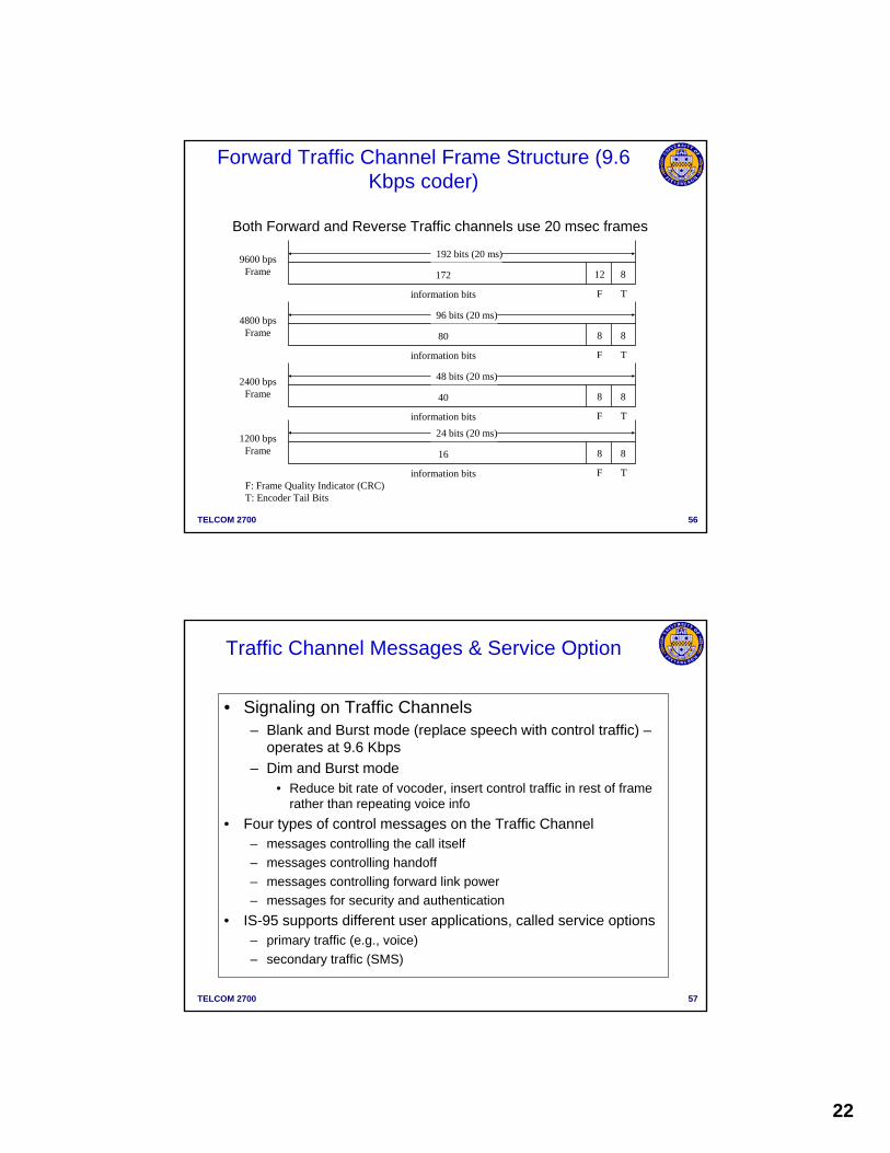
Forward Traffic Channel Frame Structure (9.6 Kbps coder)
8
T
12
F
172
information bits
192 bits (20 ms)9600 bpsFrame
8
T
8
F
80
information bits
96 bits (20 ms)4800 bpsFrame
8
T
8
F
40
information bits
48 bits (20 ms)2400 bpsFrame
8
T
8
F
16
information bits
24 bits (20 ms)1200 bpsFrame
F: Frame Quality Indicator (CRC)T: Encoder Tail Bits
Both Forward and Reverse Traffic channels use 20 msec frames
TELCOM 2700 57
Traffic Channel Messages & Service Option
• Signaling on Traffic Channels– Blank and Burst mode (replace speech with control traffic) –
operates at 9.6 Kbps– Dim and Burst mode
• Reduce bit rate of vocoder, insert control traffic in rest of frame rather than repeating voice info
• Four types of control messages on the Traffic Channel– messages controlling the call itself– messages controlling handoff– messages controlling forward link power– messages for security and authentication
• IS-95 supports different user applications, called service options– primary traffic (e.g., voice)– secondary traffic (SMS)

23
TELCOM 2700 58
Forward Link Channel Parameters
Channel Sync Paging Traffic
Data rate 1200 4800 9600 1200 2400 4800 9600 bps
Code repetition 2 2 1 8 4 2 1
Modulation symbol rate 4800 19,200 19,200 19,200 19,200 19,200 19,200 sps
PN chips/modulation symbol 256 64 64 64 64 64 64
PN chips/bit 1024 256 128 1024 512 256 128
TELCOM 2700 59
• From MS to Base Station• On Reverse Channel the Walsh codes are not
used to isolate different users, but in orthogonal signaling– Orthogonal signaling is an M-dimensional digital
modulation technique– The larger M is, the larger is the bandwidth
requirement => spread spectrum ☺• There are no pilot or synch channels• There is an “access channel” where mobile
terminals contend in random access fashion to set up a call/register location/page response
IS-95 Reverse Channel

24
TELCOM 2700 60
One Reverse CDMA Link, 1.25 MHz in the
824 – 849 MHz
AccessChannel0, PCH1
Fundamental Code Channel
Data
SupplementaryCode Channel
Data
AccessChannelN, PCH1
AccessChannel0,PCH 7
AccessChannel
TrafficChannel
1
TrafficChannel
T
SupplementaryCode Channel
Data
SupplementaryCode Channel
Data
SupplementaryCode Channel
Data
Reverse CDMA Channel
TELCOM 2700 61
Access Channel
AccessChannel
• Is used by the MS to initiate communication with the BS & to respond to Paging Channel message
Fixed data rate (4800 bps) & 20 ms frame duration
•Access Channel Message may carry•Origination of a call • Paging responses•Orders response • Data bursts•Acknowledgements to Paging Channel message•Registration
Information Bits = 88 bits Encoder Tail8 bits
96 bits (20 ms)
•Basic frame structure

25
TELCOM 2700 62
Call ManagementPAGE RESPONSE
Mobility ManagementREGISTRATION
SecurityAuthentication Challenge Response
SecurityBase Station Challenge
Call ManagementORIGINATION
Access Channel Messages
Network OperationsMessage
Sample IS-95 Messages
Access Channel is the used by phones without a call in progress to perform signaling
TELCOM 2700 63
BBF
BBF
I PN at 1.2288 Mcps
Q PN at 1.2288 Mcps
1.2288 Mcps
BlockInterleaver
SymbolRepetition
ConvolutionalEncoder
AccessMessage
4.8 kbps
Rate 1/3
14.4ksps
28.8ksps 64-ary
OrthogonalModulator
Long CodeGenerator
Long Code Mask
Access Channel
• There are up to 32 access channels per downlink paging channel– MSs are pseudorandomly distributed between the access channels
• The access channel data has 96 bits every 20 ms for a data rate of 4.8 kbps– 88 bits carry the access channel data– 8 bits are encoder tail bits

26
TELCOM 2700 64
• The 4.8 kbps data is encoded using a rate 1/3 convolutional encoder– The constraint length is 9– Minimum Hamming distance is 18– Output of the convolutional encoder is 14.4 kbps
• The output symbols are repeated to get a rate of 28.8 kbps– Every six bits is mapped into one Walsh code of 64
bits (chips) in the 64-ary orthogonal modulator– Walsh code index X is calculated as follows:
• X = c0 + 2c1 + 4c2 + 8c3 + 16c4 + 32c5• c0 is the earliest bit and c5 is the latest bit
– Example: 110001 (c5… c0) would translate into W49
Access channel
TELCOM 2700 65
Set initialpower
Sendprobe
ACKreceivedbefore
timeout?
Max probe?
Max attempts?New probe:
Raise power;Wait random time
New attempt
begin
no
no
no
yes
yes
yes
AccessFails
AccessSucceeds
Access protocol
Reverse Channel Access Protocol
27
TELCOM 2700 66
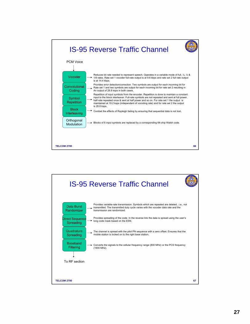
Vocoder
ConvolutionalCoding
SymbolRepetition
OrthogonalModulation
BlockInterleaving
Reduces bit rate needed to represent speech. Operates in a variable mode of full, ½, ¼ &1/8 rates. Rate set 1 vocoder full-rate output is at 9.6 kbps and rate set 2 full rate output is at 14.4 kbps. Provides error detection/correction. Two symbols are output for each incoming bit forRate set 1 and two symbols are output for each incoming bit for rate set 2 resulting inAn output of 28.8 ksps in both cases.Repetition of input symbols from the encoder. Repetition is done to maintain a constant input to the block interleaver. Full-rate symbols are not repeated and sent at full power, half-rate repeated once & sent at half power and so on. For rate set 1 the output ismaintained at 19.2 ksps (independent of vocoding rate) and for rate set 2 the output is 28.8 ksps.
Blocks of 6 input symbols are replaced by a corresponding 64-chip Walsh code.
Combat the effects of Rayleigh fading by ensuring that sequential data is not lost.
PCM Voice
IS-95 Reverse Traffic Channel
TELCOM 2700 67
Data BurstRandomizer
Direct SequenceSpreading
QuadratureSpreading
BasebandFiltering
Provides variable-rate transmission. Symbols which are repeated are deleted, .i.e., not transmitted. The transmitted duty cycle varies with the vocoder data rate and thetransmission are randomized.
Provides spreading of the code. In the reverse link the data is spread using the user’slong code mask based on the ESN.
The channel is spread with the pilot PN sequence with a zero offset. Ensures that the mobile station is locked on to the right base station.
Converts the signals to the cellular frequency range (800 MHz) or the PCS frequency(1900 MHz).
To RF section
IS-95 Reverse Traffic Channel

28
TELCOM 2700 68
Data BurstData Burst
Analog Handoff DirectionRequest Analog Service
Traffic Channel Signaling Messages
Long Code Transition ResponseLong Code Transition Response
Long Code Transition RequestLong Code Transition Request
Handoff DirectionHandoff Completion
Pilot Measurement RequestPilot Strength Measurement
Neighbor ListPower Measurement Report
DownlinkUplink
Sample IS-95 Messages
TELCOM 2700 69
BBF
BBF
I Pilot PN at 1.2288 Mcps
Q Pilot PN at 1.2288 Mcps
1.2288 Mcps
BlockInterleaver
ConvolutionalEncoder
VoiceTraffic
9.6 ksps
Rate 1/3
28.8ksps 64-ary
OrthogonalModulator
Long CodeGenerator
Long Code Mask
302.7 kcps
28.8ksps
Reverse Traffic Channel – Supplementary Code Channel
• The supplementary code channel is primarily used for data traffic (full rate is assumed)– There is no need for a data randomizer
• A single user can have many codes simultaneously to transmit data

29
TELCOM 2700 70
Reverse CDMA Channel Parameters, Rate Set 1
Channel Access Traffic
Data rate 4,800 1,200 2,400 4,800 9,600 bps Code Rate 1/3 1/3 1/3 1/3 1/3 Symbol Rate before Repetition 14,400 3,600 7,200 14,400 28,800 spsSymbol Repetition 2 8 4 2 1 Symbol Rate after Repetition 28,800 28,800 28,800 28,800 28,800 spsTransmit Duty Cycle 1 1/8 1/4 ½ 1 Code Symbols/Modulation Symbol 6 6 6 6 6 PN Chips/Modulation Symbol 256 256 256 256 256 PN chips transmitted/bit 256 128 128 128 128
TELCOM 2700 72
Call processing states
Power upTune to primary or
Secondary CDMA carrier
InitializationMS acquires pilot channel
and synch channel
Idle StateMS acquires paging channelMonitors PCH for messages
Access StateMS sends messages on ACHBS sends messages on PCH
Traffic Channel StateSpeech comm. on forward &
reverse linksAssociated control messages
using blank-and burstdim-and burst and PC
End ofcall
System responseOther than page
Or origination
Call originationPage response
Registration
Traffic channel acquisitionIdle
Handoff

30
TELCOM 2700 74
Idle Handoff and Overhead Messages
• An idle handoff occurs when– MS moves to another cell in the idle state– It determines that a new pilot signal is stronger– The MS operates in unslotted mode to acquire a
paging message• Overhead messages on the paging channel
– System parameters– Neighbor list (PN offsets of the neighbors)– CDMA channel list (list of CDMA channels)– Access parameters
• Access message sequence number• Nominal transmit power of the access channel and power
increments
TELCOM 2700 75
CDMA Properties: Near-Far Problem• A CDMA receiver cannot successfully despread the
desired signal in a high multiple-access-interference environment
Base station
• Unless a transmitter close to the receiver transmits at power lower than a transmitter farther away, the far transmitter cannot be heard
• Mobile transmit so that power levels are about equal at the base station
• Power control must be used to mitigate the near-far problem

31
TELCOM 2700 76
Power control
• In CDMA, the “near-far” problem is very significant– As users transmit at the same time and frequency, a user
close to the base station may drown the signal of a user far away from the base station
• To overcome this problem, power control is used– Open-loop power control
• Use a transmit power that is inversely proportional to the received signal strength from a base station
– Closed-loop power control• A power control bit is transmitted 800 times a second on the
forward link• The bit instructs the mobile station to either increase or
decrease the power by 1 dB
• Power control also reduces the battery power consumption making the CDMA phones somewhat smaller than their TDMA counterparts
TELCOM 2700 79
Power Control: Open Loop vs. Closed Loop
• Open loop: – Base station transmits at a known power level (a beacon) which
mobile measures to estimate the path loss– Assumes path loss in both directions is the same– Not very accurate as uplink and downlink are separated in
frequency– Useful for coarse initial estimates at mobile used in Access
channel for signalling• Closed loop:
– Signal-to-Interference Ratio (SIR) measured at the receiver and compared to a target value for SIR
– Receiver sends a power control command to transmitter to reduce or increase the power level - requires a bi-directional link
– Used in TCH – power control subchannel operates at 800 bps by puncturing downlink data with periodic bits – each power command adjusted MS power in 1 dB increments

32
TELCOM 2700 80
Closed Loop Power Control: Inner Loop vs. Outer Loop
• Inner Loop (or fast power control)– Measures received SIR, controls transmit power– Commands sent several times per frame (hence fast power
control)• Outer Loop (or slow power control)
– Measures packet error rate – Changes target SIR for inner loop– Directly modify transmit power based on FER– Commands sent once per frame (hence slow power control)
TELCOM 2700 81
• CDMA Main Advantages– resistant to narrow band
interference – resistant to multipath fading
and ISI – no hard limit on number of
users (soft capacity)– As number of users on a
frequency increase the interference level increases and BER increases for all users
– With proper limits all frequencies can be used in every cell
CDMA Capacity
10 20 30 40 50 60
.1
.01
.001
.0001
Erro
r pro
babi
lity
users
BER of CDMA system with 128 cps.
33
TELCOM 2700 82
CDMA Capacity
• CDMA is a interference limited system– Must limit number of users on a frequency to limit interference
within a cell and between cells using same frequency (All CDMA carriers can be assigned to each sector in each cell!)
– Total Interference It = Ioc + Io + No • Ioc = other cell interference, Io = own cell interference, No = Noise• uplink not downlink in CDMA systems considered the constraining
factor• Remember in direct sequence spread spectrum Processing Gain =
bandwidth of the spread signal to the bandwidth of the data signal = W/R– In IS-95 W/R = 10 log (1.23.MHz/9.6 KHz) = 21.1 dB for rate set 1, for
rate set two (14.4 kbps) => 19.3 db
• Number of traffic channels per carrier and cell function of processing gain, interference, speech coder tolerance for errors, error control coding, etc.
TELCOM 2700 83
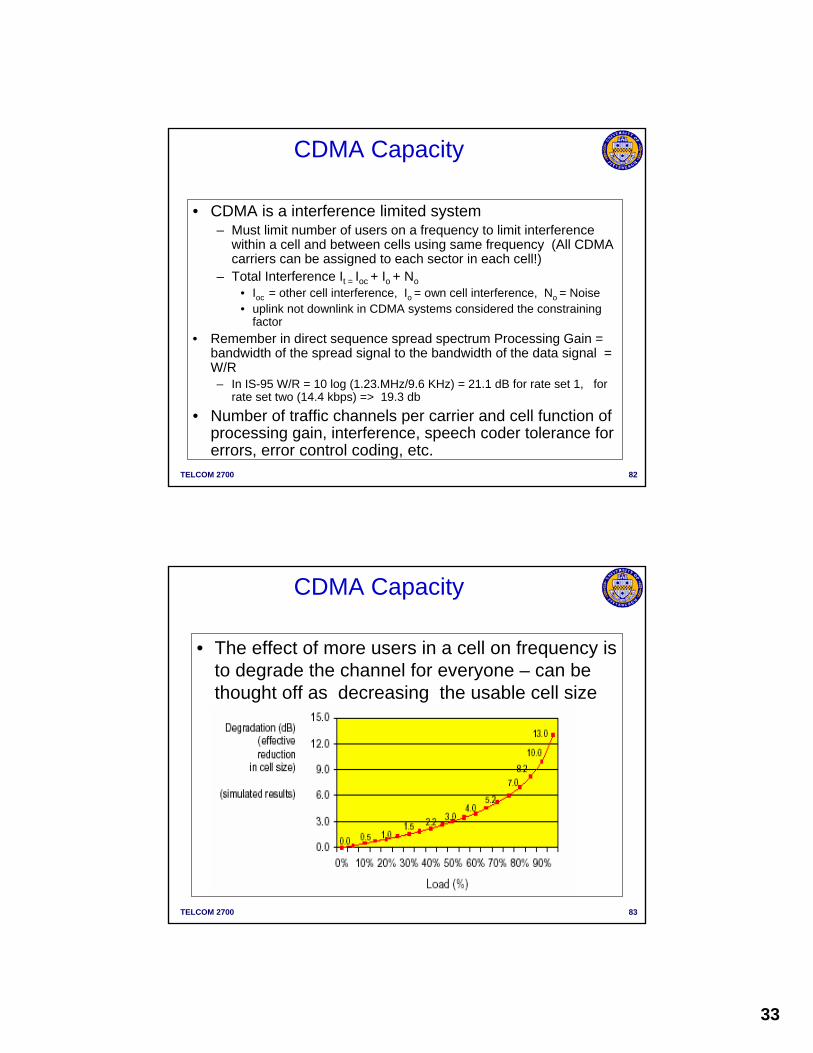
CDMA Capacity
• The effect of more users in a cell on frequency is to degrade the channel for everyone – can be thought off as decreasing the usable cell size

34
TELCOM 2700 84
Cell Breathing
• Cell breaths in & out with changing load– Cells shrink during peak hours, expand during off-peak hours
TELCOM 2700 85
Soft Handoff• If a mobile terminal moves away from a base station
and continues to increase its transmit power to maintain contact with base station – at edge of cell will need to handoff to adjacent cell
• In soft handoff a mobile terminal is required to track the pilot signals from all neighboring base stations– It will communicate with multiple base stations simultaneously
for a short while before deciding on the final candidate– This is possible because of the RAKE receiver and direct-
sequence spread-spectrum– Not all handoffs will be soft!– hard handoff when CDMA to AMPS and inter–CDMA
frequency channel handoffs– Note soft handoff reduces system capacity as mobile tying up
2 traffic channels

35
TELCOM 2700 86
CDMA System Concepts: Soft Handovers
• Mobile located in the area of overlap of multiple base stations • Transmission:
– Uplink: No difference– Downlink: BSC/MSC sends out a copy of the same packet to each
base station
• Reception:– Uplink: Each base station
demodulates packet, BSC/MSC picks the “better packet” (macro-diversity combining)
– Downlink: The mobile combines the signals using a Rake receiver (micro-diversity combining)
• Two power control loops
BSC
TELCOM 2700 88
• The mobile terminal maintains a list of pilot channels that it can hear and classifies them into four categories– Active set – pilots currently used by the mobile terminal (up
to three pilots can be used)– Candidate set – pilots that are not in the active set, but have
sufficient signal strength for demodulation– Neighbour set – pilots of base stations of neighbouring cells
that are indicated by the network through the paging channel– Remaining set – all other possible pilots in the system
• Several thresholds are used by the mobile terminal to move pilots from one set to another
Soft Handoff Procedure

36
TELCOM 2700 89
conversation
Neighbor pilot > threshold:Add neighbor to candidate set
PILOT STRENGTH MEASUREMENT
Select channelat new base
New active set
HANDOFF DIRECTION
HANDOFF COMPLETE
Traffic channel infoProgram correlators
SwitchTerminal New BaseOld Base
Soft handoff procedure
Soft Handoff Procedure
TELCOM 2700 90
conversation
Active signal > threshold:
PILOT STRENGTH MEASUREMENT
HANDOFF DIRECTION
HANDOFF COMPLETE
release correlators
SwitchTerminal New BaseOld Base
Select signal forsource decoder
HANDOFF DIRECTION
HANDOFF COMPLETE
conversation
Soft Handoff Procedure

37
TELCOM 2700 91
• IS-95 specifies three basic types of soft handoff(a) Softer: handoff between two sectors of same cell(b) Soft: handoff between sectors of adjacent cells(c) Soft-softer: candidates for handoff include two sectors from the
same cell and a sector from adjacent cell
Soft Handoff
TELCOM 2700 92
• Combinations of the three types can occur for example– Soft-Soft: 3 adjacent cells
• Downside of soft handoff – call uses multiple traffic channels over air (increases interference
and decreases capacity– Call uses multiple trunk in portion of wired network – figure shows typical soft handoff percentages in a live IS-95 network
in Dallas, Texas– Note in handoff state 85% of the time!
Soft Handoff

38
TELCOM 2700 93
Encryption
• CAVE (cellular authentication and voice encyrption) algorithm used
• Uses a 64 bit A-key along with ESN and Random number to generate 128 bit shared secret data (SSD)
• SSD divided into two 64 bit blocks– (A for authentication, B for encryption)
• Challenge/Response technique for Authentication
• Random number used to create key for encryption of voice and data
TELCOM 2700 94
Example of C-R: IS-41C
MSBTS
BSC
HLR
VLR
AuC
O
MSC
OMC
EIR
Generate RAND
Compute AUTHU*=CAVEkey(RAND)
Compute AUTHU=CAVEkey(RAND)
Compare AUTHU* and AUTHU
send AUTHU

39
TELCOM 2700 95
CAVE
• Challenge/Response based on random number and SSD
TELCOM 2700 96
IS-95 Summary • Direct Sequence Spread Spectrum• Code Division Multiple Access/FDMA/FDD• Reuse frequencies in every cell K = 1!• Soft Handoff supported• Dim and Burst signalling• Digital Voice
– QCELP fixed rate 14.4Kbps coder– variable rate QCELP coder: 9.6, 4.8, 2.4, 1.2 Kbps
• Dual Mode (AMPS/CDMA) Dual Band (900, 1900 MHz bands)• Low power handsets (sleep mode)• Power Control important (800bps)• Security: CDMA signal + CAVE encryption • Air Interface Standard Only• Large increase in capacity over AMPS