is e c o m .c o m (b) hardware description (rel_02).pdfraisecom iscom5508 (b) hardware description...
TRANSCRIPT

ISCOM5508 (B)
Hardware Description
(Rel_02)
www.raisecom.com

Raisecom Technology Co., Ltd. provides customers with comprehensive technical support and services. For any
assistance, please contact our local office or company headquarters.
Website: http://www.raisecom.com
Tel: 8610-82883305
Fax: 8610-82883056
Email: [email protected]
Address: Raisecom Building, No. 11, East Area, No. 10 Block, East Xibeiwang Road, Haidian District, Beijing,
P.R.China
Postal code: 100094
-----------------------------------------------------------------------------------------------------------------------------------------
Notice
Copyright © 2017
Raisecom
All rights reserved.
No part of this publication may be excerpted, reproduced, translated or utilized in any form or by any means,
electronic or mechanical, including photocopying and microfilm, without permission in Writing from Raisecom
Technology Co., Ltd.
is the trademark of Raisecom Technology Co., Ltd.
All other trademarks and trade names mentioned in this document are the property of their respective holders.
The information in this document is subject to change without notice. Every effort has been made in the
preparation of this document to ensure accuracy of the contents, but all statements, information, and
recommendations in this document do not constitute the warranty of any kind, express or implied.

Raisecom
ISCOM5508 (B) Hardware Description Preface
Raisecom Proprietary and Confidential
Copyright © Raisecom Technology Co., Ltd. i
Preface
Objectives This document describes the chassis, hardware components, and cables of the ISCOM5508,
including hardware features, components, supported functions and technical specifications of
each component, and appearance and technical specifications of cables.
Versions The following table lists the product versions related to this document.
Product name Hardware version Software version
ISCOM5508 B.00 or later V2.61 or later
Related manuals The following table lists manuals and their contents related to the ISCOM5508.
Name Description
ISCOM5508 (B) Hardware
Description
This document mainly introduces product overview,
components, fiber and cables, pluggable modules,
lookup table of LEDs, and lookup table of weight and
power consumption.
ISCOM5508 (B) Configuration
Guide
This guide mainly introduces basic configuration, data
service configuration, multicast service configuration,
VoIP service configuration, CATV service
configuration, TDM service configuration, MAC
address table configuration, VLAN configuration,
Spanning Tree configuration, routing configuration,
DHCP configuration, QoS configuration, OAM
configuration, link security configuration, and system
management configuration.

Raisecom
ISCOM5508 (B) Hardware Description Preface
Raisecom Proprietary and Confidential
Copyright © Raisecom Technology Co., Ltd. ii
Conventions
Symbol conventions
The symbols that may be found in this document are defined as follows.
Symbol Description
Indicate a hazard with a medium or low level of risk which, if
not avoided, could result in minor or moderate injury.
Indicate a potentially hazardous situation that, if not avoided,
could cause equipment damage, data loss, and performance
degradation, or unexpected results.
Provide additional information to emphasize or supplement
important points of the main text.
Indicate a tip that may help you solve a problem or save time.
General conventions
Convention Description
Times New Roman Normal paragraphs are in Times New Roman.
Arial Paragraphs in Warning, Caution, Notes, and Tip are in Arial.
Boldface Buttons and navigation path are in Boldface.
Italic Book titles are in italics.
Lucida Console Terminal display is in Lucida Console.
Book Antiqua Heading 1, Heading 2, Heading 3, and Block are in Book Antiqua.
Change history Updates between document versions are cumulative. Therefore, the latest document version
contains all updates made to previous versions.
Issue 02 (2015-12-08)
Second commercial release
Fixed known bugs.
Modified configurations of cables.
Raisecom
ISCOM5508 (B) Hardware Description Preface
Raisecom Proprietary and Confidential
Copyright © Raisecom Technology Co., Ltd. iii
Issue 01 (2013-10-18)
Initial commercial release
Raisecom
ISCOM5508 (B) Hardware Description Contents
Raisecom Proprietary and Confidential
Copyright © Raisecom Technology Co., Ltd. iv
Contents
1 Overview ......................................................................................................................................... 1
1.1 Introduction ...................................................................................................................................................... 1
1.2 Appearance and slots ........................................................................................................................................ 2
1.2.1 Appearance of chassis ............................................................................................................................. 2
1.2.2 Distribution of slots ................................................................................................................................. 2
1.3 Physical parameters .......................................................................................................................................... 2
2 Components ................................................................................................................................... 4
2.1 Overview of components ................................................................................................................................. 4
2.1.1 Classification of components .................................................................................................................. 4
2.1.2 Appearances of components .................................................................................................................... 5
2.1.3 Hardware information label .................................................................................................................... 7
2.2 MCC (EPSC) .................................................................................................................................................... 8
2.2.1 Introduction ............................................................................................................................................. 8
2.2.2 Panel and slots......................................................................................................................................... 8
2.2.3 Interfaces ................................................................................................................................................. 8
2.2.4 LEDs ..................................................................................................................................................... 10
2.2.5 Technical specifications ........................................................................................................................ 10
2.3 4 EPON subcard (EP4B) ................................................................................................................................ 11
2.3.1 Introduction ........................................................................................................................................... 11
2.3.2 Panel and slots....................................................................................................................................... 11
2.3.3 Interfaces ............................................................................................................................................... 11
2.3.4 LEDs ..................................................................................................................................................... 12
2.3.5 Technical specifications ........................................................................................................................ 12
2.4 4 GE subcard (GE4B) .................................................................................................................................... 12
2.4.1 Introduction ........................................................................................................................................... 12
2.4.2 Panel and slots....................................................................................................................................... 12
2.4.3 Interfaces ............................................................................................................................................... 13
2.4.4 LEDs ..................................................................................................................................................... 13
2.4.5 Technical specifications ........................................................................................................................ 14
2.5 AC power module (RPA1101-SI-220S12) ..................................................................................................... 14
2.5.1 Introduction ........................................................................................................................................... 14
2.5.2 Panel and slots....................................................................................................................................... 15
Raisecom
ISCOM5508 (B) Hardware Description Contents
Raisecom Proprietary and Confidential
Copyright © Raisecom Technology Co., Ltd. v
2.5.3 Interfaces ............................................................................................................................................... 15
2.5.4 LEDs ..................................................................................................................................................... 15
2.5.5 Technical specifications ........................................................................................................................ 16
2.6 DC power module (RPD1101-48S12) ............................................................................................................ 16
2.6.1 Introduction ........................................................................................................................................... 16
2.6.2 Panel and slots....................................................................................................................................... 17
2.6.3 Interfaces ............................................................................................................................................... 17
2.6.4 LEDs ..................................................................................................................................................... 17
2.6.5 Technical specifications ........................................................................................................................ 18
2.7 Fan module (FANS306) ................................................................................................................................. 18
2.7.1 Introduction ........................................................................................................................................... 18
2.7.2 Panel and slots....................................................................................................................................... 18
2.7.3 LEDs ..................................................................................................................................................... 19
2.7.4 Technical specifications ........................................................................................................................ 19
3 Fiber and cables ........................................................................................................................... 20
3.1 Fiber ............................................................................................................................................................... 20
3.1.1 Introduction ........................................................................................................................................... 20
3.1.2 Connector .............................................................................................................................................. 21
3.1.3 Wiring ................................................................................................................................................... 23
3.2 Ethernet cable ................................................................................................................................................. 23
3.2.1 Introduction ........................................................................................................................................... 23
3.2.2 Appearance ............................................................................................................................................ 23
3.2.3 Technical specifications ........................................................................................................................ 23
3.3 Console cable ................................................................................................................................................. 26
3.3.1 Appearance ............................................................................................................................................ 27
3.3.2 Wiring ................................................................................................................................................... 27
3.3.3 Techinical specifications ....................................................................................................................... 27
3.4 DC power cable .............................................................................................................................................. 28
3.4.1 Introduction ........................................................................................................................................... 28
3.4.2 Appearance ............................................................................................................................................ 28
3.4.3 Technical specifications ........................................................................................................................ 29
3.5 AC power cable .............................................................................................................................................. 29
3.5.1 Introduction ........................................................................................................................................... 29
3.5.2 Appearance ............................................................................................................................................ 30
3.5.3 Technical specifications ........................................................................................................................ 30
3.6 Ground cable .................................................................................................................................................. 31
3.6.1 Introduction ........................................................................................................................................... 31
3.6.2 Appearance ............................................................................................................................................ 31
3.6.3 Technical specifications ........................................................................................................................ 32
4 Pluggable modules ..................................................................................................................... 34
4.1 1000 Mbit/s SFP optical module .................................................................................................................... 34

Raisecom
ISCOM5508 (B) Hardware Description Contents
Raisecom Proprietary and Confidential
Copyright © Raisecom Technology Co., Ltd. vi
4.1.1 Functions and appearance ..................................................................................................................... 34
4.1.2 Label ..................................................................................................................................................... 34
4.1.3 Technical specifications ........................................................................................................................ 35
4.2 1000 Mbit/s SFP electrical module ................................................................................................................ 36
4.2.1 Functions and appearance ..................................................................................................................... 36
4.2.2 Techinical specifications ....................................................................................................................... 36
4.3 PON SFP optical module ............................................................................................................................... 37
4.3.1 Functions and appearance ..................................................................................................................... 37
4.3.2 Label ..................................................................................................................................................... 37
4.3.3 Technical specifications ........................................................................................................................ 38
5 Lookup table of LEDs................................................................................................................. 39
6 Lookup table of weight and power consumption ................................................................ 41
7 Appendix ...................................................................................................................................... 43
7.1 Terms .............................................................................................................................................................. 43
7.2 Acronyms and abbreviations .......................................................................................................................... 44

Raisecom
ISCOM5508 (B) Hardware Description Figures
Raisecom Proprietary and Confidential
Copyright © Raisecom Technology Co., Ltd. vii
Figures
Figure 1-1 Appearance of the ISCOM5508 chassis ............................................................................................... 2
Figure 1-2 Distribution of slots on the ISCOM5508 .............................................................................................. 2
Figure 2-1 Appearance of the MCC (EPSC) .......................................................................................................... 5
Figure 2-2 Appearance of the EP4B subcard ......................................................................................................... 5
Figure 2-3 Appearance of the GE4B subcard ......................................................................................................... 6
Figure 2-4 Appearance of the power module ......................................................................................................... 6
Figure 2-5 Appearance of the fan module .............................................................................................................. 6
Figure 2-6 Hardware information label on the ISCOM5508 ................................................................................. 7
Figure 2-7 Panel of the EPSC card ......................................................................................................................... 8
Figure 2-8 Panel of the EP4B subcard ................................................................................................................. 11
Figure 2-9 Panel of the GE4B subcard ................................................................................................................. 13
Figure 2-10 Panel of the RPA1101 power module ............................................................................................... 15
Figure 2-11 Panel of the RPD1101 power module ............................................................................................... 17
Figure 2-12 Panel of the FANS306 module ......................................................................................................... 19
Figure 3-1 LC/PC fiber connector ........................................................................................................................ 21
Figure 3-2 SC/PC fiber connector ........................................................................................................................ 22
Figure 3-3 FC/PC fiber connector ........................................................................................................................ 22
Figure 3-4 Ethernet cable ..................................................................................................................................... 23
Figure 3-5 Wiring of the straight-through cable wiring ....................................................................................... 24
Figure 3-6 Wiring of the 100 Mbit/s crossover cable ........................................................................................... 25
Figure 3-7 Wiring of the 1000 Mbit/s crossover cable ......................................................................................... 26
Figure 3-8 Configuration cable ............................................................................................................................ 27
Figure 3-9 PINs and wiring .................................................................................................................................. 27
Figure 3-10 DC power cable ................................................................................................................................ 29
Figure 3-11 European standard AC power cable .................................................................................................. 30
Figure 3-12 American standard AC power cable.................................................................................................. 30

Raisecom
ISCOM5508 (B) Hardware Description Figures
Raisecom Proprietary and Confidential
Copyright © Raisecom Technology Co., Ltd. viii
Figure 3-13 Ground cable .................................................................................................................................... 32
Figure 3-14 OT terminal ...................................................................................................................................... 32
Figure 4-1 1000 Mbit/s SFP optical module ........................................................................................................ 34
Figure 4-2 Label of the 1000 Mbit/s SFP optical module .................................................................................... 35
Figure 4-3 1000 Mbit/s SFP electrical module ..................................................................................................... 36
Figure 4-4 PON SFP optical module .................................................................................................................... 37
Figure 4-5 Label of the PON SFP optical module ................................................................................................ 37

Raisecom
ISCOM5508 (B) Hardware Description Tables
Raisecom Proprietary and Confidential
Copyright © Raisecom Technology Co., Ltd. ix
Tables
Table 1-1 Physical parameters of the ISCOM5508 ................................................................................................ 3
Table 2-1 Components of the ISCOM5508 ............................................................................................................ 4
Table 2-2 Items on the hardware information label ................................................................................................ 7
Table 2-3 Interfaces on the EPSC card ................................................................................................................... 8
Table 2-4 Parameters of the Console interface ....................................................................................................... 9
Table 2-5 Parameters of the SNMP interface ......................................................................................................... 9
Table 2-6 Parameters of the GE interface based on 10/100/1000BASE-T standard .............................................. 9
Table 2-7 LEDs on the EPSC card ....................................................................................................................... 10
Table 2-8 Technical specifications of the EPSC card ........................................................................................... 11
Table 2-9 Interfaces on the EP4B subcard ........................................................................................................... 11
Table 2-10 LEDs on the EP4B subcard ................................................................................................................ 12
Table 2-11 Technical specifications of the EP4B subcard .................................................................................... 12
Table 2-12 Interfaces on the GE4B subcard ......................................................................................................... 13
Table 2-13 Parameters of the 1000BASE-X SFP optical interface ...................................................................... 13
Table 2-14 LEDs on the GE4B subcard ............................................................................................................... 14
Table 2-15 Technical specifications of the GE4B subcard ................................................................................... 14
Table 2-16 Interface on the RPA1101 power module ........................................................................................... 15
Table 2-17 LEDs on the RPA1101 power module................................................................................................ 16
Table 2-18 Technical specifications of the RPA1101 power module ................................................................... 16
Table 2-19 Interface on the RPD1101 power module .......................................................................................... 17
Table 2-20 LEDs on the RPD1101 power module ............................................................................................... 17
Table 2-21 Technical specifications of the RPD1101 power module ................................................................... 18
Table 2-22 LEDs on the FANS306 module .......................................................................................................... 19
Table 2-23 Technical specifications of the FANS306 module .............................................................................. 19
Table 3-1 Type and usage of the fiber .................................................................................................................. 20
Table 3-2 Fiber connectors ................................................................................................................................... 21

Raisecom
ISCOM5508 (B) Hardware Description Tables
Raisecom Proprietary and Confidential
Copyright © Raisecom Technology Co., Ltd. x
Table 3-3 Wiring of the fiber ................................................................................................................................ 23
Table 3-4 Wiring of the straight-through cable .................................................................................................... 24
Table 3-5 Technical specifications of the Ethernet cable ..................................................................................... 26
Table 3-6 PIN definitions of the Console interface and RJ45 interface ............................................................... 27
Table 3-7 Technical specifications of the Console cable ...................................................................................... 28
Table 3-8 Technical specifications of the DC power cable .................................................................................. 29
Table 3-9 AC power cable of the ISCOM5508 .................................................................................................... 30
Table 3-10 Technical specifications of the European AC power cable................................................................. 30
Table 3-11 Technical specifications of the American AC power cable ................................................................ 31
Table 3-12 Technical specifications of the ground cable ...................................................................................... 32
Table 3-13 Technical specifications of the OT terminal ....................................................................................... 33
Table 4-1 Model of the 1000 Mbit/s SFP optical module ..................................................................................... 35
Table 4-2 Technical specifications of the 1000BASE-X SFP optical module ...................................................... 35
Table 4-3 Technical specifications of the 1000BASE-T SFP electrical module ................................................... 36
Table 4-4 Model of the PON SFP optical module ................................................................................................ 37
Table 4-5 Technical specifications of the CLASS B+ optical module ................................................................. 38
Table 5-1 LEDs of the ISCOM5508 ..................................................................................................................... 39
Table 6-1 Weight and power consumption of the ISCOM5508 ........................................................................... 41

Raisecom
ISCOM5508 (B) Hardware Description 1 Overview
Raisecom Proprietary and Confidential
Copyright © Raisecom Technology Co., Ltd. 1
1 Overview
This chapter describes orientation, appearance, and physical parameters of the ISCOM5508,
including the following sections:
Introduction
Appearance and slots
Physical parameters
1.1 Introduction The ISCOM5508 is a next-generation, small-capacity, 1U, and plug-in Ethernet Passive
Optical Network (EPON) Optical Line Terminal (OLT). It is oriented to industrial customers,
providing rich features and flexible networking schemes to meet low-density and long-
distance requirements for optical fiber access.
Work with the Optical Network Unit (ONU) as the OLT in EPON to construct the low-
cost, high-bandwidth, and long-distance access network, thus addressing problems of
small -and medium-scale fiber access.
Meet Fiber to The Home (FTTH) and Fiber to The Building (FTTB) networking
requirements.
Support automatically collecting information about the power grid, and meet
requirements on building the intelligent community.
Support providing triple play services using the single-fiber.
Meet networking requirements on bidirectional reconstruction of the Hybrid Fiber
Coaxial (HFC) network (EPON+EoC).
The ISCOM5508 can be installed in the following scenarios:
ETSI 600-mm cabinet
19-inch 450-mm cabinet
19-inch 600-mm cabinet
Open rack
Workbench

Raisecom
ISCOM5508 (B) Hardware Description 1 Overview
Raisecom Proprietary and Confidential
Copyright © Raisecom Technology Co., Ltd. 2
When installing the chassis to the 19-inch 600-mm cabinet, you need to purchase brackets applicable to the cabinet.
1.2 Appearance and slots
1.2.1 Appearance of chassis
The ISCOM5508 is a cartridge device, which is flexible to be deployed. Dimensions of the
chassis are: 440 mm (Width) × 266 mm (Depth) × 44 mm (Height) (without brackets).
Figure 1-1 shows the appearance of the ISCOM5508 chassis.
Figure 1-1 Appearance of the ISCOM5508 chassis
1.2.2 Distribution of slots
The ISCOM5508 provides the following 6 slots:
1 Main Control Card (MCC) slot (slot 1)
2 extended subcard slots (slot 2 and slot 3)
1 fan module slot (slot 6)
2 power module slots (slot 4 and slot 5)
Figure 1-2 shows distribution of slots on the ISCOM5508.
Figure 1-2 Distribution of slots on the ISCOM5508
1.3 Physical parameters Table 1-1 lists physical parameters of the ISCOM5508.

Raisecom
ISCOM5508 (B) Hardware Description 1 Overview
Raisecom Proprietary and Confidential
Copyright © Raisecom Technology Co., Ltd. 3
Table 1-1 Physical parameters of the ISCOM5508
Parameter Description
Dimensions 440 mm (Width) × 266 mm (Depth) × 44 mm
(Height) (without brackets)
Standard
configuration
Weight 5.51 kg
Power consumption 40 W
Full
configuration
Weight 6.24 kg
Power consumption 63 W
DC power Rated voltage -48 VDC
Voltage range -38 to -72 VDC
AC power Rated voltage 110/220 VAC
Voltage range 100–240 VAC
Frequency 50/60 Hz
Standard configuration: chassis, MCC (EPSC), 2 power modules, and 1 fan
module. Full configuration: chassis, MCC (EPSC), 2 extended subcards, 2 power modules,
and 1 fan module.

Raisecom
ISCOM5508 (B) Hardware Description 2 Components
Raisecom Proprietary and Confidential
Copyright © Raisecom Technology Co., Ltd. 4
2 Components
This chapter describes the appearances, dimensions, and technical specifications of
components of the ISCOM5508, including the following sections:
Overview of components
MCC (EPSC)
4 EPON subcard (EP4B)
4 GE subcard (GE4B)
AC power module (RPA1101-SI-220S12)
DC power module (RPD1101-48S12)
Fan module (FANS306)
2.1 Overview of components
2.1.1 Classification of components
The ISCOM5508 is composed of the following four types of components:
MCC
Extended subcard
Power module
Fan module
Table 2-1 lists components of the ISCOM5508.
Table 2-1 Components of the ISCOM5508
Component Name Description
MCC EPSC Control, management, aggregation, and
switching card
Extended subcard EP4B 4 EPON subcards
GE4B 4 GE subcards
Power module RPA1101 110/220 VAC power module

Raisecom
ISCOM5508 (B) Hardware Description 2 Components
Raisecom Proprietary and Confidential
Copyright © Raisecom Technology Co., Ltd. 5
Component Name Description
RPD1101 -48 VDC power module
Fan module FANS306 Fan module
2.1.2 Appearances of components
Appearance of MCC
Figure 2-1 shows the appearance of the MCC (EPSC).
Figure 2-1 Appearance of the MCC (EPSC)
Appearance of expansion subcard
Figure 2-2 shows the appearance of the EP4B subcard.
Figure 2-2 Appearance of the EP4B subcard
Figure 2-3 shows the appearance of the GE4B subcard.

Raisecom
ISCOM5508 (B) Hardware Description 2 Components
Raisecom Proprietary and Confidential
Copyright © Raisecom Technology Co., Ltd. 6
Figure 2-3 Appearance of the GE4B subcard
Appearance of power module
Figure 2-4 shows the appearance of the power module.
Figure 2-4 Appearance of the power module
Appearance of fan module
Figure 2-5 shows the appearance of the fan module.
Figure 2-5 Appearance of the fan module

Raisecom
ISCOM5508 (B) Hardware Description 2 Components
Raisecom Proprietary and Confidential
Copyright © Raisecom Technology Co., Ltd. 7
2.1.3 Hardware information label
Hardware information of ISCOM5508 components is described by a label pasted on the
Printed Circuit Board (PCB) to facilitate you to view it, as shown in Figure 2-6.
Figure 2-6 Hardware information label on the ISCOM5508
The position of hardware information labels may be different because the layouts of elements are different, so search for it carefully.
Table 2-2 lists items on the hardware information label.
Table 2-2 Items on the hardware information label
Parameter Description
P/N Name and type of the component
REV Hardware version of the component, where "A" means a release
version and "00" means a build
Bar code Bar code of the component

Raisecom
ISCOM5508 (B) Hardware Description 2 Components
Raisecom Proprietary and Confidential
Copyright © Raisecom Technology Co., Ltd. 8
2.2 MCC (EPSC)
2.2.1 Introduction
The EPSC card is the main unit for accessing, processing, and switching services. It provides
4 EPON optical interfaces, 2 GE electrical interfaces (RJ45), and 4 GE optical interfaces
(SFP). Moreover, it supports managing and maintaining the ISCOM5508 through the SNMP
interface and Console interface.
2.2.2 Panel and slots
The EPSC card can be inserted into slot 1 only.
Figure 2-7 shows the panel of the EPSC card.
Figure 2-7 Panel of the EPSC card
2.2.3 Interfaces
There are 12 interfaces on the EPSC card.
Table 2-3 lists interfaces on the EPSC card.
Table 2-3 Interfaces on the EPSC card
Interface Type Usage Description
CONSOLE RJ45 Local maintenance
serial interface
RS-232 serial interface
SNMP RJ45 Remote network
management
interface
10/100BASE-T self-adaptive
electrical interface
GE 1/2 RJ45 Ethernet service
interface
10/100/1000BASE-T self-adaptive
electrical interface
GE 3/4/5/6 SFP Ethernet service
interface
Supported optical module type:
1000BASE-X
PON 1/2/3/4 PON SFP EPON service
interface
Supported optical module type:
1000BASE-PX20-D
For details of the optical module, see chapter 4 Pluggable modules.
Table 2-4 lists parameters of the Console interface.

Raisecom
ISCOM5508 (B) Hardware Description 2 Components
Raisecom Proprietary and Confidential
Copyright © Raisecom Technology Co., Ltd. 9
Table 2-4 Parameters of the Console interface
Parameter Description
Connector RJ45
Working mode Duplex UART
Electrical features RS-232
Baud rate 9600 baud
Data bit 8
Parity check None
Stop bit 1
Flow control None
Cable specifications 4-core shielded cable
Table 2-5 lists parameters of the SNMP interface.
Table 2-5 Parameters of the SNMP interface
Parameter Description
Connector RJ45
Interface rate 10/100BASE-T auto-negotiation
Wiring Support adaption to straight-through and crossover cable in host
mode
Compliant standard IEEE 802.3
Table 2-6 lists parameters of the GE interface.
Table 2-6 Parameters of the GE interface based on 10/100/1000BASE-T standard
Parameter Description
Connector RJ45
Working mode 10/100/1000 Mbit/s auto-negotiation Full duplex and half duplex auto-negotiation
Cable specifications When the working mode is 10 Mbit/s or 100 Mbit/s, we
recommend using the Cat 5 UTP cable. When the working mode is 1000 Mbit/s, we recommend
using Cat 5 or better STP cable.
Compliant standard IEEE 802.3
Supported network protocol IP

Raisecom
ISCOM5508 (B) Hardware Description 2 Components
Raisecom Proprietary and Confidential
Copyright © Raisecom Technology Co., Ltd. 10
2.2.4 LEDs
There are 16 LEDs on the EPSC card, where 6 LEDs are integrated with the RJ45 interface.
Table 2-7 lists LEDs on the EPSC card.
Table 2-7 LEDs on the EPSC card
LED Status Description
PWR Green Power LED
Green: the power supply is working properly. Off: the power supply is working improperly.
SYS Green System working LED
Fast blinking green (4 Hz): the system is initializing. Slow blinking green (0.5 Hz): the system is working
properly. Off: the system is working improperly or the card is
inserted improperly.
LNK/ACT
(SNMP
integrated LED)
Green Line working LED
Green: the interface is connected properly. Blinking green: the interface is transmitting data. Off: the interface is disconnected or connected improperly.
100M
(SNMP
integrated LED)
Yellow Line working rate LED
Yellow: the electrical interface is working at 100 Mbit/s. Off: the electrical interface is working at 10 Mbit/s.
LNK/ACT
1/2/3/4
(SFP optical
interface)
Green Line working LED
Green: the interface is connected properly. Blinking green: the interface is transmitting data. Off: the interface is disconnected or connected improperly.
LNK/ACT 1/2
(RJ45 electrical
interface
integrated LED)
Green Line working LED
Green: the interface is connected properly. Blinking green: the interface is transmitting data. Off: the interface is disconnected or connected improperly.
1000M
(RJ45 electrical
interface
integrated LED)
Yellow Line working rate LED
Yellow: the electrical interface is working at 1000 Mbit/s. Off: the electrical interface is working at 100 Mbit/s.
LNK
1/2/3/4
Green PON interface working LED Green: the PON interface is connected properly and there
is a registered ONU working on the interface or there is a
laser-always-on ONU. Off: the PON interface is disconnected or there is no
registered ONU working on the interface.
2.2.5 Technical specifications
Table 2-8 lists technical specifications of the EPSC card.

Raisecom
ISCOM5508 (B) Hardware Description 2 Components
Raisecom Proprietary and Confidential
Copyright © Raisecom Technology Co., Ltd. 11
Table 2-8 Technical specifications of the EPSC card
Parameter Description
Dimensions 259.3 mm (Width) × 243.4 mm (Depth) × 19.8 mm (Height)
Weight 0.89 kg
Power consumption ≤ 32 W
2.3 4 EPON subcard (EP4B)
2.3.1 Introduction
The EP4B subcard is the EPON interface subcard of the ISCOM5508, providing 4 EPON SFP
interfaces.
2.3.2 Panel and slots
The EP4B subcard can be inserted into slot 2 or slot 3 of the ISCOM5508.
Figure 2-8 shows the panel of the EP4B subcard.
Figure 2-8 Panel of the EP4B subcard
2.3.3 Interfaces
There are 4 interfaces on the EP4B subcard.
Table 2-9 lists interfaces on the EP4B subcard.
Table 2-9 Interfaces on the EP4B subcard
Interface Type Usage Description
PON 1/2/3/4 PON SFP EPON service
interface
Supported optical module type:
1000BASE-PX20-D
For details of the optical module, see chapter 4 Pluggable modules.

Raisecom
ISCOM5508 (B) Hardware Description 2 Components
Raisecom Proprietary and Confidential
Copyright © Raisecom Technology Co., Ltd. 12
2.3.4 LEDs
There are 6 LEDs on the EP4B subcard.
Table 2-10 lists LEDs on the EP4B subcard.
Table 2-10 LEDs on the EP4B subcard
LED Status Description
PWR Green Power LED
Green: the power supply is working properly. Off: the power supply is working improperly.
SYS Green System working LED
Fast blinking green (4 Hz): the system is being initialized. Slow blinking green (0.5 Hz): the system is working properly. Off: the system is working improperly or the card is inserted
improperly.
LNK
1/2/3/4 Green PON interface working LED
Green: the PON interface is connected properly and there is a
registered ONU working on the interface. Off: the PON interface is disconnected or there is no registered
ONU working on the interface.
2.3.5 Technical specifications
Table 2-11 lists technical specifications of the EP4B subcard.
Table 2-11 Technical specifications of the EP4B subcard
Parameter Description
Dimensions 129.4 mm (Width) × 243.4 mm (Depth) × 19.8 mm (Height)
Weight 0.37 kg
Power consumption ≤ 10 W
2.4 4 GE subcard (GE4B)
2.4.1 Introduction
The GE4B subcard is the GE interface subcard of the ISCOM5508, providing 4 SFP-type GE
interfaces and being compatible with 1000 Mbit/s Ethernet optical and electrical modules.
2.4.2 Panel and slots
The GE4B subcard can be inserted into slot 2 or slot 3.

Raisecom
ISCOM5508 (B) Hardware Description 2 Components
Raisecom Proprietary and Confidential
Copyright © Raisecom Technology Co., Ltd. 13
Figure 2-9 shows the panel of the GE4B subcard.
Figure 2-9 Panel of the GE4B subcard
2.4.3 Interfaces
There are 4 interfaces on the GE4B subcard.
Table 2-12 lists interfaces on the GE4B subcard.
Table 2-12 Interfaces on the GE4B subcard
Interface Type Usage Description
GE 1/2/3/4 SFP 1000 Mbit/s Ethernet
service interface
Supported optical module type:
1000BASE-X
Supported electrical module type:
1000BASE-T
Table 2-13 lists parameters of the SFP optical interface.
Table 2-13 Parameters of the 1000BASE-X SFP optical interface
Parameter Description
Connector LC/PC
Optical interface properties Depend on the SFP optical module.
Working mode Full duplex
Compliant standard IEEE 802.3
Supported network protocol IP
For details of the optical module, see chapter 4 Pluggable modules. When the GE4B card uses the 1000BASE-T electrical module, the interface rate
should be configured to "forced 1000M" mode. For details, see ISCOM5508 (B) Configuration Guide.
2.4.4 LEDs
There are 6 LEDs on the GE4B subcard.
Table 2-14 lists LEDs on the GE4B subcard.

Raisecom
ISCOM5508 (B) Hardware Description 2 Components
Raisecom Proprietary and Confidential
Copyright © Raisecom Technology Co., Ltd. 14
Table 2-14 LEDs on the GE4B subcard
LED Status Description
PWR Green Power LED
Green: the power supply is working properly. Off: the power supply is working improperly.
SYS Green System working LED
Fast blinking green (4 Hz): the system is initializing. Slow blinking green (0.5 Hz): the system is working properly. Off: the system is working improperly or the card is inserted
improperly.
LNK/ACT
1/2/3/4
Green Ethernet interface working LED
Green: the Ethernet interface is connected properly. Blinking green: the Ethernet interface is transmitting data. Off: the Ethernet interface is disconnected or connected
improperly.
2.4.5 Technical specifications
Table 2-15 lists technical specifications of the GE4B subcard.
Table 2-15 Technical specifications of the GE4B subcard
Parameter Description
Dimensions 129.4 mm (Width) × 243.4 mm (Depth) × 19.8 mm (Height)
Weight 0.23 kg
Power consumption ≤ 4 W
2.5 AC power module (RPA1101-SI-220S12)
2.5.1 Introduction
The RPA1101-SI-220S12 (hereinafter referred to as RPA1101) module is the AC power
module of the ISCOM5508. It supports the following features:
Wide range of voltage input: 100–240 VAC
Rated output voltage: 12 V; rated output current: 8.3 A
Output overvoltage protection and output overcurrent protection
Input surge current suppression and voltage suppression
Power status LED
Operating temperature: -10 to +70°C

Raisecom
ISCOM5508 (B) Hardware Description 2 Components
Raisecom Proprietary and Confidential
Copyright © Raisecom Technology Co., Ltd. 15
Turn off the power switch or disconnect the power connection before installing or
removing the power cable. Ensure that the label on the power cable is correct before connecting the power
cable. Use the power cable compliant with required specifications.
2.5.2 Panel and slots
The RPA1101 power module can be inserted into slot 4 or slot 5.
Figure 2-10 shows the panel of the RPA1101 power module.
Figure 2-10 Panel of the RPA1101 power module
2.5.3 Interfaces
There is 1 interface on the RPA1101 power module.
Table 2-16 lists the interface on the RPA1101 power module.
Table 2-16 Interface on the RPA1101 power module
Interface Usage
100V-240V–50/60Hz AC power interface/receptacle socket
2.5.4 LEDs
There are 3 LEDs on the RPA1101 power module.
Table 2-17 lists LEDs on the RPA1101 power module.
Raisecom
ISCOM5508 (B) Hardware Description 2 Components
Raisecom Proprietary and Confidential
Copyright © Raisecom Technology Co., Ltd. 16
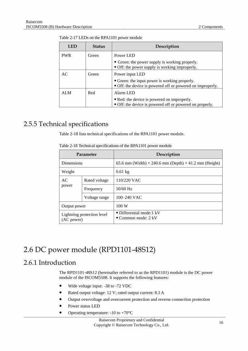
Table 2-17 LEDs on the RPA1101 power module
LED Status Description
PWR Green Power LED
Green: the power supply is working properly. Off: the power supply is working improperly.
AC Green Power input LED
Green: the input power is working properly. Off: the device is powered off or powered on improperly.
ALM Red Alarm LED
Red: the device is powered on improperly. Off: the device is powered off or powered on properly.
2.5.5 Technical specifications
Table 2-18 lists technical specifications of the RPA1101 power module.
Table 2-18 Technical specifications of the RPA1101 power module
Parameter Description
Dimensions 65.6 mm (Width) × 240.6 mm (Depth) × 41.2 mm (Height)
Weight 0.61 kg
AC
power Rated voltage 110/220 VAC
Frequency 50/60 Hz
Voltage range 100–240 VAC
Output power 100 W
Lightning protection level
(AC power)
Differential mode:1 kV Common mode: 2 kV
2.6 DC power module (RPD1101-48S12)
2.6.1 Introduction
The RPD1101-48S12 (hereinafter referred to as the RPD1101) module is the DC power
module of the ISCOM5508. It supports the following features:
Wide voltage input: -38 to -72 VDC
Rated output voltage: 12 V; rated output current: 8.3 A
Output overvoltage and overcurrent protection and reverse connection protection
Power status LED
Operating temperature: -10 to +70°C
Raisecom
ISCOM5508 (B) Hardware Description 2 Components
Raisecom Proprietary and Confidential
Copyright © Raisecom Technology Co., Ltd. 17
2.6.2 Panel and slots
The RPD1101 power module can be inserted into slot 4 or slot 5.
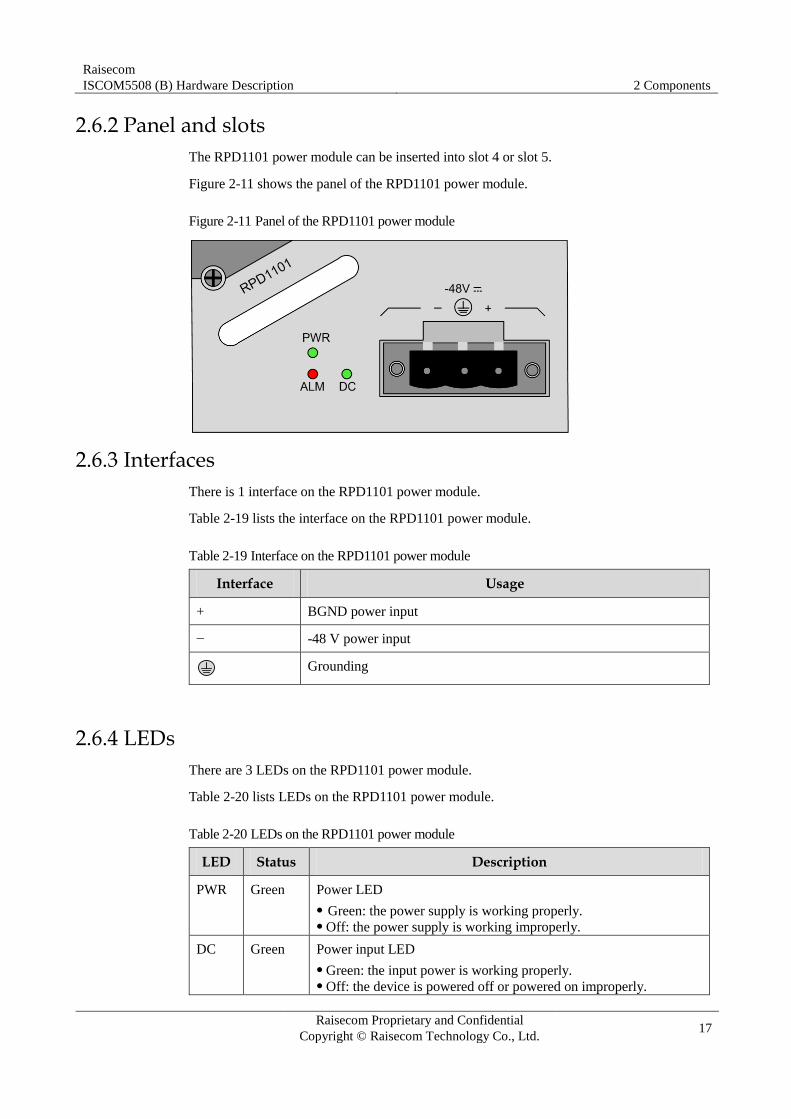
Figure 2-11 shows the panel of the RPD1101 power module.
Figure 2-11 Panel of the RPD1101 power module
2.6.3 Interfaces
There is 1 interface on the RPD1101 power module.
Table 2-19 lists the interface on the RPD1101 power module.
Table 2-19 Interface on the RPD1101 power module
Interface Usage
+ BGND power input
− -48 V power input
Grounding
2.6.4 LEDs
There are 3 LEDs on the RPD1101 power module.
Table 2-20 lists LEDs on the RPD1101 power module.
Table 2-20 LEDs on the RPD1101 power module
LED Status Description
PWR Green Power LED
Green: the power supply is working properly. Off: the power supply is working improperly.
DC Green Power input LED
Green: the input power is working properly. Off: the device is powered off or powered on improperly.

Raisecom
ISCOM5508 (B) Hardware Description 2 Components
Raisecom Proprietary and Confidential
Copyright © Raisecom Technology Co., Ltd. 18
LED Status Description
ALM Red Alarm LED
Red: the device is powered on improperly. Off: the device is powered off or powered on properly.
2.6.5 Technical specifications
Table 2-21 lists technical specifications of the RPD1101 power module.
Table 2-21 Technical specifications of the RPD1101 power module
Parameter Description
Dimensions 65.6 mm (Width) × 240.6 mm (Depth) × 41.2 mm (Height)
Weight 0.49 kg
DC power Rated voltage -48 VDC
Voltage range -38 to -72 VDC
Output power 100 W
2.7 Fan module (FANS306)
2.7.1 Introduction
The FANS306 module is the fan module of the ISCOM5508. It supports the following
features:
Support fan monitoring. The system monitors the working status of the fan and an alarm
is generated when the fan fails.
Support adjusting the rotational speed of the fan manually or automatically.
Support hot swapping.
2.7.2 Panel and slots
The FANS306 module can be inserted into slot 6 of the ISCOM5508.
Figure 2-12 shows the panel of the FANS306 module.

Raisecom
ISCOM5508 (B) Hardware Description 2 Components
Raisecom Proprietary and Confidential
Copyright © Raisecom Technology Co., Ltd. 19
Figure 2-12 Panel of the FANS306 module
2.7.3 LEDs
There are 2 LEDs on the FANS306 module.
Table 2-22 lists LEDs on the FANS306 module.
Table 2-22 LEDs on the FANS306 module
LED Status Description
PWR Green Power LED
Green: the power supply is working properly. Off: the power supply is working improperly.
ALM Red Alarm LED
Red: the module is working improperly and an alarm is generated. Off: the module is working properly.
2.7.4 Technical specifications
Table 2-23 lists technical specifications of the FANS306 module.
Table 2-23 Technical specifications of the FANS306 module
Parameter Description
Dimensions 41.9 mm (Width) × 230.1 mm (Depth) × 41.1 mm (Height)
Weight 0.3 kg
Power consumption 3 W

Raisecom
ISCOM5508 (B) Hardware Description 3 Fiber and cables
Raisecom Proprietary and Confidential
Copyright © Raisecom Technology Co., Ltd. 20
3 Fiber and cables
This chapter describes fiber and cables of the ISCOM5508, including the following sections:
Fiber
Ethernet cable
Console cable
DC power cable
AC power cable
Ground cable
3.1 Fiber
3.1.1 Introduction
The ISCOM5508 supports the Single-Mode Fiber (SMF) and Multi-Mode Fiber (MMF).
These two kinds of fiber are same in appearance while different in color. The yellow one is a
SMF and the orange one is a MMF.
The ISCOM5508 can be connected to the Optical Distribution Frame (ODF) or optical
interfaces of other devices through fiber.
Table 3-1 lists the type and usage of the fiber.
Table 3-1 Type and usage of the fiber
Usage Local connector Remote connector Type Standard
Connect the ISCOM5508 to
the ODF through the
Ethernet optical interface.
Connect the Ethernet optical
interface on the
ISCOM5508 to optical
interfaces on other devices.
LC/PC LC/PC 2 mm SMF ITU-T G.652
2 mm MMF
LC/PC FC/PC 2 mm SMF
2 mm MMF
LC/PC SC/PC 2 mm SMF
2 mm MMF

Raisecom
ISCOM5508 (B) Hardware Description 3 Fiber and cables
Raisecom Proprietary and Confidential
Copyright © Raisecom Technology Co., Ltd. 21
Usage Local connector Remote connector Type Standard
Connect the ISCOM5508 to
the ODF through the PON
interface.
SC/PC LC/PC 2 mm SMF
SC/PC FC/PC 2 mm SMF
SC/PC SC/PC 2 mm SMF
Choose the connector type and jumper cable length reasonably based on the on-
site requirements. The supported connector of the optical interface depends on the optical module. Choose a connector suitable for the optical interface. Otherwise, it may increase
additional loss of fiber links, reduce transmission quality of services, or even damage the connector and optical interface.
3.1.2 Connector
Fiber connectors are different in shape, ferrule end-face, and pigtail sheath color, as shown in
Table 3-2.
Table 3-2 Fiber connectors
Connector Description Pigtail sheath color
LC/PC Clamping square fiber connector/micro-convex
grinding-and-polishing ferrule end-face
Blue
SC/PC Square fiber connector/ micro-convex grinding-
and-polishing ferrule end-face
Blue
LC/PC fiber connector
Figure 3-1 shows the appearance of the LC/PC fiber connector.
Figure 3-1 LC/PC fiber connector
When connecting or removing the LC/PC fiber connector, align the connector with the optical
interface, and do not rotate the fiber. Do as below:

Raisecom
ISCOM5508 (B) Hardware Description 3 Fiber and cables
Raisecom Proprietary and Confidential
Copyright © Raisecom Technology Co., Ltd. 22
To connect the fiber, align the head of the fiber with the optical interface and insert the
fiber into the interface gently.
To remove the fiber, press down the clamping connector, and push the fiber head
inwards, and then pull the fiber out.
SC/PC fiber connector
Figure 3-2 shows the appearance of the SC/PC fiber connector.
Figure 3-2 SC/PC fiber connector
When connecting or removing the SC/PC fiber connector, align the connector with the optical
interface, and do not rotate the fiber. Do as below:
To connect the fiber, align the head of the fiber with the optical interface and insert the
fiber into the interface gently.
To remove the fiber, push the fiber head inwards, and then pull the fiber out.
FC/PC fiber connector
Figure 3-3 shows the appearance of the FC/PC fiber connector.
Figure 3-3 FC/PC fiber connector
When connecting or removing the FC/PC fiber connector, align the connector with the optical
interface, and do not rotate the fiber. Do as below:
To connect the fiber, align the fiber head with the optical interface. Be careful not to
damage the ceramic tube inside the optical interface. After inserting the fiber to the
bottom, rotate the screw sleeve clockwise to fasten the optical interface.

Raisecom
ISCOM5508 (B) Hardware Description 3 Fiber and cables
Raisecom Proprietary and Confidential
Copyright © Raisecom Technology Co., Ltd. 23
To remove the fiber, rotate the screw sleeve counterclockwise. When the screw sleeve is
loosened, pull the fiber out.
3.1.3 Wiring
Table 3-3 lists wiring of the fiber.
Table 3-3 Wiring of the fiber
Wiring Local optical interface Direction of optical signals
Peer optical interface
Single-fiber
connection
Optical interface <-> Optical interface
Dual-fiber
connection
Optical interface Tx -> Optical interface Rx
Optical interface Rx <- Optical interface Tx
3.2 Ethernet cable
3.2.1 Introduction
The Ethernet cable of the ISCOM5508 can be used to:
Connect the Ethernet electrical interface of the ISCOM5508 to other devices.
Connect the SNMP interface of the ISCOM5508 to the NView NMS system.
The Ethernet interface on the ISCOM5508 is adaptive to straight-through cable mode and
crossover cable mode. So both kinds of Ethernet cables can be used.
The Ethernet cable needs to be made on site.
3.2.2 Appearance
Figure 3-4 shows the appearance of the Ethernet cable.
Figure 3-4 Ethernet cable
3.2.3 Technical specifications
The Ethernet cable can be divided into two types:

Raisecom
ISCOM5508 (B) Hardware Description 3 Fiber and cables
Raisecom Proprietary and Confidential
Copyright © Raisecom Technology Co., Ltd. 24
Straight-through cable: both two RJ45 connectors of the straight-through cable follow
EIA/TIA568B wiring.
Crossover cable: one RJ45 connector of the crossover cable follows EIA/TIA 568A
wiring; the other RJ45 connector follows EIA/TIA 568B wiring.
Straight-through cable
Table 3-4 lists wiring of the straight-through cable.
Table 3-4 Wiring of the straight-through cable
Connector 1 (RJ45) EIA/TIA568B Connector 2 (RJ45) EIA/TIA568B
PIN 1 White/Orange PIN 1 White/Orange
PIN 2 Orange PIN 2 Orange
PIN 3 White/Green PIN 3 White/Green
PIN 4 Blue PIN 4 Blue
PIN 5 White/Blue PIN 5 White/Blue
PIN 6 Green PIN 6 Green
PIN 7 White/Brown PIN 7 White/Brown
PIN 8 Brown PIN 8 Brown
Figure 3-5 shows wiring of the straight-through cable.
Figure 3-5 Wiring of the straight-through cable wiring

Raisecom
ISCOM5508 (B) Hardware Description 3 Fiber and cables
Raisecom Proprietary and Confidential
Copyright © Raisecom Technology Co., Ltd. 25
Crossover cable
Wiring of the 100 Mbit/s crossover cable is different from that of the 1000 Mbit/s crossover
cable.
One RJ45 connector of the 100 Mbit/s crossover cable follows EIA/TIA568A wiring; the
other RJ45 connector follows EIA/TIA568B wiring.
Figure 3-6 shows wiring of the 100 Mbit/s crossover cable.
Figure 3-6 Wiring of the 100 Mbit/s crossover cable
The 1000 Mbit/s crossover cable uses all 8 wires of the twisted-pair cable. The crossover is
PIN 1 to PIN 3, PIN 2 to PIN 6, PIN 4 to PIN 7, and PIN 5 to PIN 8.
Figure 3-7 shows wiring of the 1000 Mbit/s crossover cable.

Raisecom
ISCOM5508 (B) Hardware Description 3 Fiber and cables
Raisecom Proprietary and Confidential
Copyright © Raisecom Technology Co., Ltd. 26
Figure 3-7 Wiring of the 1000 Mbit/s crossover cable
Table 3-5 lists technical specifications of the Ethernet cable.
Table 3-5 Technical specifications of the Ethernet cable
Parameter Description
Name CBL-ETH-RJ45/RJ45-D
Color Dark grey
Cable type Cat 3 or Cat 5 UTP cable, or STP cable
Connector type RJ45 connector
Number of cores 8
Length The letter D indicates the length, which can be customized. For
example, if the customer requires 2-meter cables, they are named
CBL-ETH-RJ45/RJ45-2m/RoHS.
3.3 Console cable The configuration cable is used to connect the Console interface of the ISCOM5508 and the
RS-232 serial interface of the maintenance console, and transmit configuration data signals.
The maintenance console troubleshoots and maintains the ISCOM5508 through the Console
interface.
The configuration cable is a 4-core UTP cable. Connectors at the two ends are:
RJ45 connector: connect the Console interface of the ISCOM5508.
DB9 female connector: connect the RS-232 serial interface of the maintenance console.

Raisecom
ISCOM5508 (B) Hardware Description 3 Fiber and cables
Raisecom Proprietary and Confidential
Copyright © Raisecom Technology Co., Ltd. 27
3.3.1 Appearance
Figure 3-8 shows the appearance of the configuration cable.
Figure 3-8 Configuration cable
3.3.2 Wiring
Figure 3-9 shows the PINs and wiring of the RS-232 serial interface and RJ45 Ethernet
interface.
Figure 3-9 PINs and wiring
3.3.3 Techinical specifications
PIN definition
Table 3-6 lists PIN definitions of the Console interface and RJ45 interface
Table 3-6 PIN definitions of the Console interface and RJ45 interface
PIN No. PIN function
Device (RJ45) Maintenance console (DB9)
PIN 1 NC DCD
PIN 2 NC RxD
PIN 3 RxD TxD
PIN 4 GND DTR

Raisecom
ISCOM5508 (B) Hardware Description 3 Fiber and cables
Raisecom Proprietary and Confidential
Copyright © Raisecom Technology Co., Ltd. 28
PIN No. PIN function
Device (RJ45) Maintenance console (DB9)
PIN 5 GND GND
PIN 6 TxD DSR
PIN 7 NC RTS
PIN 8 NC CTS
PIN 9 – RI
Cable specifications
Table 3-7 lists technical specifications of the Console cable.
Table 3-7 Technical specifications of the Console cable
Parameter Description
Name CBL-RS232-DB9F/RJ45-2m/RoHS
Color White
Cable type Cat 3 UTP
Connector type DB9 female connector and RJ45 connector
Number of cores 4
Length 2 m
3.4 DC power cable
3.4.1 Introduction
The DC power cable supplies -48 VDC power from the power souring equipment to the
power interface on the RPD1101 module of the ISCOM5508, and then transmits power to the
entire device.
3.4.2 Appearance
The DC power cable is composed of the DC power connector and coaxial cable, as shown in
Figure 3-10.

Raisecom
ISCOM5508 (B) Hardware Description 3 Fiber and cables
Raisecom Proprietary and Confidential
Copyright © Raisecom Technology Co., Ltd. 29
Figure 3-10 DC power cable
3.4.3 Technical specifications
Table 3-8 lists technical specifications of the DC power cable.
Table 3-8 Technical specifications of the DC power cable
Parameter Description
Name POL-DC-DSUB/NC1-6m
Color Black (-48 V power cable -) Red (-48 V ground cable +)
Connector D connector and bare wire
Cross-sectional area of inner conductor 8.37 mm2
Wire gauge of inner conductor 8 AWG
DC resistance of inner conductor 2.11 Ω/km
Maximum current 37.7 A
Cable length 6 m
Working temperature 0–40°C
3.5 AC power cable
3.5.1 Introduction
The AC power cable supplies 110/220 VAC power from the power souring equipment to the
power interface on the RPA1101 module of the ISCOM5508, and then transmits power to the
entire device.
Types of the AC power cable of the ISCOM5508 depend on different regional standards, as
shown in Table 3-9.

Raisecom
ISCOM5508 (B) Hardware Description 3 Fiber and cables
Raisecom Proprietary and Confidential
Copyright © Raisecom Technology Co., Ltd. 30
Table 3-9 AC power cable of the ISCOM5508
Regional standard Name
European standard POL-AC-European 3-pin/C13 connector-0.75mm2-D/RoHS
American standard POL-AC-American 3-pin/C13 connector-18AWG-D/RoHS
3.5.2 Appearance
The AC power cable which meets European standard is composed of a European French
mode 3-pin plug and a receptacle, as shown in Figure 3-11.
Figure 3-11 European standard AC power cable
The AC power cable which meets American standard is composed of an American 3-pin plug
and a receptacle, as shown in Figure 3-12.
Figure 3-12 American standard AC power cable
3.5.3 Technical specifications
Table 3-10 lists technical specifications of the European AC power cable.
Table 3-10 Technical specifications of the European AC power cable
Parameter Description
Name POL-AC-European 3-pin/C13 connector-0.75 mm2-D/RoHS
Connector 1 European 3-pin plug
Connector 2 IEC60320-C13 connector
Cable
color
Outer Black (PVC insulating layer)
Inner Blue (N), brown (L), and yellow/green strip (E)
Conductor
gauge
3×0.75 mm2

Raisecom
ISCOM5508 (B) Hardware Description 3 Fiber and cables
Raisecom Proprietary and Confidential
Copyright © Raisecom Technology Co., Ltd. 31
Parameter Description
Length The letter D indicates the length, which can be customized. For
example, if the customer requires 1.5-meter cables, they are named
POL-AC-European 3-pin/receptacle-0.75 mm2-1.5 m/RoHS.
Table 3-11 lists technical specifications of the American AC power cable.
Table 3-11 Technical specifications of the American AC power cable
Parameter Description
Name POL-AC-American 3-pin/C13 connector-18AWG-D/RoHS
Connector 1 NMEA5-15 American 3-pin plug
Connector 2 IEC60320-C13 connector
Cable
color
Outer Black (PVC insulating layer)
Inner White (N), black (L), and yellow strip (E)
Conductor
gauge
18 AWG/3C
Length The letter D indicates the length, which can be customized. For
example, if the customer requires 1.5-meter cables, they are named
POL-AC-American 3-pin/receptacle-18AWG-1.5m/RoHS.
3.6 Ground cable
Connecting the ground cable properly is an important guarantee to lightning protection, anti-electric shock, and anti-interference. The ISCOM5508 must be connected to the ground cable correctly during installation, which helps avoid personal injury and equipment damage.
3.6.1 Introduction
The ground cable is used to ground the ISCOM5508.
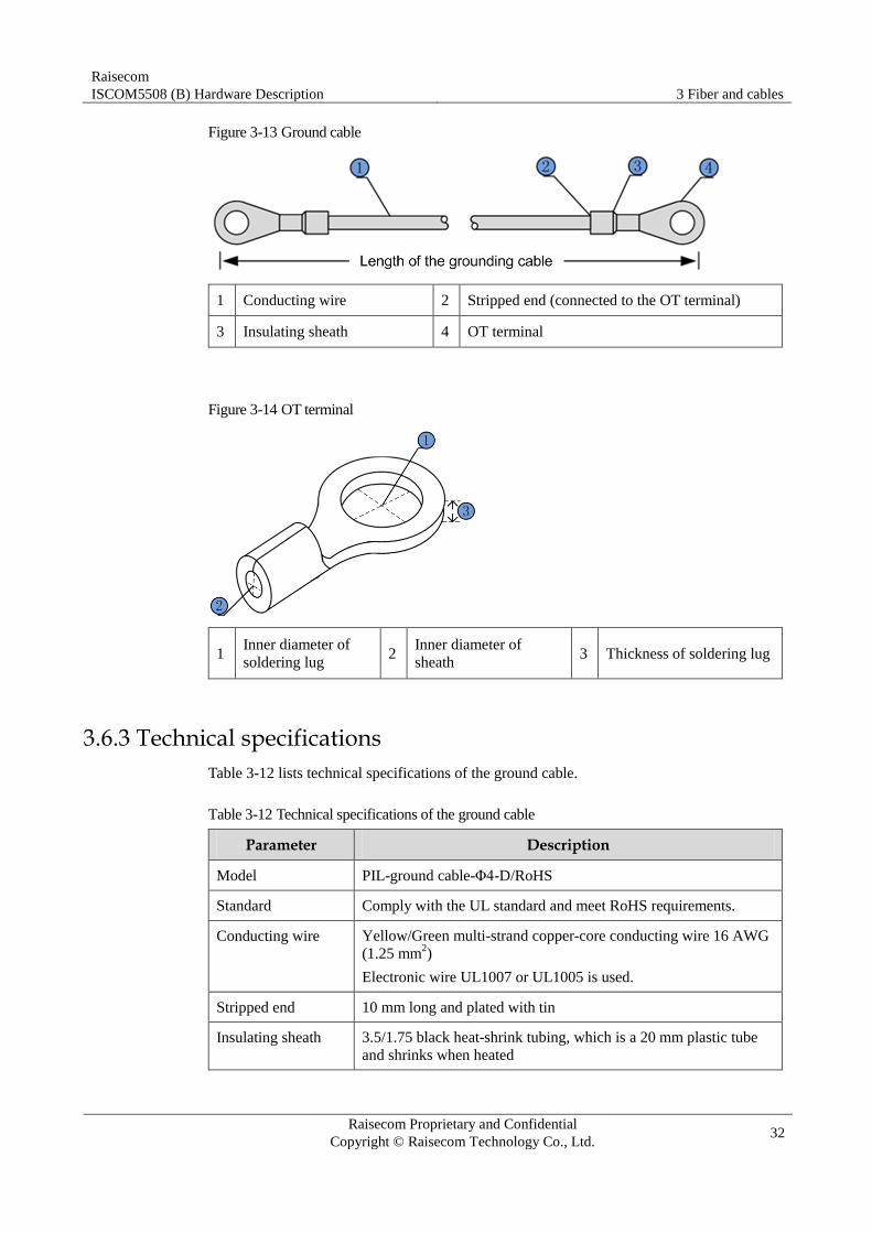
3.6.2 Appearance
The ground cable is composed of the ground terminal and conductive wire. In general, ground
terminals are OT bare-pressure terminals; and the conductive wire is a yellow/green copper
soft flame-retardant conducting wire.
Figure 3-13 and Figure 3-14 show the ground cable and OT terminal respectively.
Raisecom
ISCOM5508 (B) Hardware Description 3 Fiber and cables
Raisecom Proprietary and Confidential
Copyright © Raisecom Technology Co., Ltd. 32
Figure 3-13 Ground cable
1 Conducting wire 2 Stripped end (connected to the OT terminal)
3 Insulating sheath 4 OT terminal
Figure 3-14 OT terminal
1 Inner diameter of
soldering lug 2
Inner diameter of
sheath 3 Thickness of soldering lug
3.6.3 Technical specifications
Table 3-12 lists technical specifications of the ground cable.
Table 3-12 Technical specifications of the ground cable
Parameter Description
Model PIL-ground cable-Φ4-D/RoHS
Standard Comply with the UL standard and meet RoHS requirements.
Conducting wire Yellow/Green multi-strand copper-core conducting wire 16 AWG
(1.25 mm2)
Electronic wire UL1007 or UL1005 is used.
Stripped end 10 mm long and plated with tin
Insulating sheath 3.5/1.75 black heat-shrink tubing, which is a 20 mm plastic tube
and shrinks when heated

Raisecom
ISCOM5508 (B) Hardware Description 3 Fiber and cables
Raisecom Proprietary and Confidential
Copyright © Raisecom Technology Co., Ltd. 33
Parameter Description
Welding technology The conducting wire and OT terminals adopt solderless pressed
connection.
Error in length of
conducting wire
±5 mm
The letter D in the model indicates the length, which can be customized. For example, if the customer requires 2-meter cables, they are named PIL-ground cable-Φ4-2m/RoHS.
Table 3-13 lists technical specifications of the OT terminal.
Table 3-13 Technical specifications of the OT terminal
Parameter Description
Model Protective grounding round pressed terminal (M4)
Standard JB2436-78
Specifications 4.3 soldering lug Inner diameter of soldering lug: 4 mm Outer diameter of soldering lug: ≤ 8 mm Inner diameter of sheath: 2.1 mm Thickness of soldering lug: ≥ 0.6 mm
Cross-sectional area of
conducting wire
16–15 AWG (1.2–1.5 mm2)
The ISCOM5508 is delivered without the ground cable. If required, prepare or
make ground cables on site. The ground cable cannot be longer than 30 m and should be as short as possible;
otherwise, a grounding bar should be used.

Raisecom
ISCOM5508 (B) Hardware Description 4 Pluggable modules
Raisecom Proprietary and Confidential
Copyright © Raisecom Technology Co., Ltd. 34
4 Pluggable modules
This chapter describes pluggable modules of the ISCOM5508, including the following
sections:
1000 Mbit/s SFP optical module
1000 Mbit/s SFP electrical module
PON SFP optical module
4.1 1000 Mbit/s SFP optical module
4.1.1 Functions and appearance
The 1000 Mbit/s Small Form-factor Pluggables (SFP) optical module is applicable to the
1000 Mbit/s telecommunication network. It is integrated with sending and receiving features.
Figure 4-1 shows the appearance of the 1000 Mbit/s SFP optical module.
Figure 4-1 1000 Mbit/s SFP optical module
4.1.2 Label
There is a label on the bottom of the SFP optical module, which describes the model of the
SFP optical module, as shown in Figure 4-2.

Raisecom
ISCOM5508 (B) Hardware Description 4 Pluggable modules
Raisecom Proprietary and Confidential
Copyright © Raisecom Technology Co., Ltd. 35
Figure 4-2 Label of the 1000 Mbit/s SFP optical module
Table 4-1 describes the model of the 1000 Mbit/s SFP optical module.
Table 4-1 Model of the 1000 Mbit/s SFP optical module
Field Description
USFP Internal identifier, indicating it is a universal SFP
Gb Transmission rate: 1.25 Gbit/s
S1 Transmission distance: M: 0.55 km S1: 15 km S2: 40 km S3:80 km
D Support DDM.
01 Internal identifier, different values of which indicate the same function
R Comply with RoHS.
1310nm Tx wavelength: 1310 nm
SM Single-mode fiber
DDM Support link detection.
21CFR (J) Comply with U.S. DHHS 21CFR (J).
Class1 Comply with class 1 laser safety.
4.1.3 Technical specifications
Table 4-2 lists technical specifications of the 1000BASE-X SFP optical module.
Table 4-2 Technical specifications of the 1000BASE-X SFP optical module
Model Tx wavelength
(nm)
Interface type
Mode Tx optical power (dBm)
Min. overload
point (dBm)
Extinction ratio (dB)
Rx sensitivity
(dBm)
Transmission
distance (km)
USFP-
Gb/M-D-R
850 (LC/PC) Dual-fiber
multi-mode
-9.5 to -
3
0 9 -17 0.55
USFP-
Gb/S1-D-R
1310
(LC/PC)
Dual-fiber
single-mode
-10 to -3 -3 9 -21 15

Raisecom
ISCOM5508 (B) Hardware Description 4 Pluggable modules
Raisecom Proprietary and Confidential
Copyright © Raisecom Technology Co., Ltd. 36
Model Tx wavelength
(nm)
Interface type
Mode Tx optical power (dBm)
Min. overload
point (dBm)
Extinction ratio (dB)
Rx sensitivity
(dBm)
Transmission
distance (km)
USFP-
Gb/S2-D-R
1550
(LC/PC)
Dual-fiber
single-mode
-3 to 2 -3 9 -21 40
USFP-
Gb/S3-D-R
1550
(LC/PC)
Dual-fiber
single-mode
-3 to 2 -9 9 -30 80
4.2 1000 Mbit/s SFP electrical module
4.2.1 Functions and appearance
The 1000 Mbit/s SFP electrical module is applicable to the 1000 Mbit/s telecommunication
network. It is integrated with sending and receiving features.
Figure 4-3 shows the appearance of the 1000 Mbit/s SFP electrical module.
Figure 4-3 1000 Mbit/s SFP electrical module
4.2.2 Techinical specifications
Table 4-3 lists technical specifications of the 1000BASE-T SFP electrical module.
Table 4-3 Technical specifications of the 1000BASE-T SFP electrical module
Model Rate Transmission distance Description
USFP-GE-R 1.25 Gbit/s 100 m 1000BASE-T Auto-negotiation is disabled. SerDes interface

Raisecom
ISCOM5508 (B) Hardware Description 4 Pluggable modules
Raisecom Proprietary and Confidential
Copyright © Raisecom Technology Co., Ltd. 37
4.3 PON SFP optical module
4.3.1 Functions and appearance
The PON SFP optical module can be applied to the PON system.
Figure 4-4 shows the appearance of the PON SFP optical module.
Figure 4-4 PON SFP optical module
4.3.2 Label
The EPON interface on the ISCOM5508 supports the optical module compliant with the
1000BASE-PX20-D standard.
There is a label on the bottom of the SFP optical module, which describes the model of the
SFP optical module, as shown in Figure 4-5.
Figure 4-5 Label of the PON SFP optical module
Table 4-4 describes the model of the PON SFP optical module.
Table 4-4 Model of the PON SFP optical module
Field Description
GSFP Internal identifier, indicating it is a PON SFP module
PX20 Comply with PX20+ specification.
D Downstream direction, indicating it is an OLT optical module
M Support link monitoring.
03 Internal identifier, different values of which indicate the same
function
R Comply with RoHS.
EPON-OLT-PX20+ Comply with PX20+ specification and be applied to OLT optical
module
21CFR (J) Comply with U.S. DHHS 21CFR (J).

Raisecom
ISCOM5508 (B) Hardware Description 4 Pluggable modules
Raisecom Proprietary and Confidential
Copyright © Raisecom Technology Co., Ltd. 38
Field Description
Class1 Comply with class 1 laser safety.
4.3.3 Technical specifications
Table 4-5 lists technical specifications of the CLASS B+ optical module.
Table 4-5 Technical specifications of the CLASS B+ optical module
Parameter Description
Model GSFP-PX20DM-R
Transmission rate Tx: 1.25 Gbit/s Rx: 1.25 Gbit/s
Interface type SC/PC
Max. transmission distance 20 km
Fiber mode Single-mode fiber
Central wavelength (Laser type) Tx: 1490 nm (DFB) Rx: 1310 nm (APD/TIA)
Tx optical power 2–7 dBm
Extinction ratio 9 dB
Rx sensitivity -30 dBm
Minimum overload point -6 dBm
RSSI link monitoring Supported

Raisecom
ISCOM5508 (B) Hardware Description 5 Lookup table of LEDs
Raisecom Proprietary and Confidential
Copyright © Raisecom Technology Co., Ltd. 39
5 Lookup table of LEDs
Table 5-1 lists LEDs of the ISCOM5508.
Table 5-1 LEDs of the ISCOM5508
LED Status Description
PWR Green Power LED
Green: the power supply is working properly. Off: the power supply is working improperly.
SYS Green System working LED
Blinking green: the system is working properly. Off: the system is working improperly or the card is
inserted improperly.
LNK/ACT
1/2/3/4
(SFP optical
interface)
Green Line working LED
Green: the interface is connected properly. Blinking green: the interface is transmitting data. Off: the interface is disconnected or connected
improperly.
LNK/ACT 1/2
(RJ45 electrical
interface
integrated LED)
Green Line working LED
Green: the interface is connected properly. Blinking green: the interface is transmitting data. Off: the interface is disconnected or connected
improperly.
1000M
(RJ45 electrical
interface
integrated LED)
Yellow Electrical interface working rate LED
Yellow: the electrical interface is working at 1000 Mbit/s. Off: the electrical interface is working at 100 Mbit/s or the
interface fails.
LNK 1/2/3/4 Green PON interface working LED Green: the PON interface is connected properly and there
is a registered ONU working on the interface or there is a
laser-always-on ONU. Off: the PON interface is disconnected or there is no
registered ONU working on the interface.

Raisecom
ISCOM5508 (B) Hardware Description 5 Lookup table of LEDs
Raisecom Proprietary and Confidential
Copyright © Raisecom Technology Co., Ltd. 40
LED Status Description
ALM Red Alarm LED
Red: the device is working improperly and an alarm is
generated. Off: the device is working properly.
AC Green AC power working LED
Green: the power module is working properly. Off: the power module is working improperly.
DC Green DC power working LED
Green: the power module is working properly. Off: the power module is working improperly.

Raisecom
ISCOM5508 (B) Hardware Description 6 Lookup table of weight and power consumption
Raisecom Proprietary and Confidential
Copyright © Raisecom Technology Co., Ltd. 41
6 Lookup table of weight and power consumption
Table 6-1 lists weight and power consumption of the ISCOM5508.
Table 6-1 Weight and power consumption of the ISCOM5508
Component Parameter
Standard configuration Weight 5.51 kg
Power consumption 40 W
Full configuration Weight 6.24 kg
Power consumption 63 W
EPSC Weight 0.89 kg
Power consumption ≤ 32 W
EP4B Weight 0.37 kg
Power consumption ≤ 10 W
GE4B Weight 0.23 kg
Power consumption ≤ 4 W
RPA1101 Weight 0.61 kg
Output power consumption 100 W
RPD1101 Weight 0.49 kg
Output power consumption 100 W
FANS306 Weight 0.3 kg
Power consumption ≤ 3 W

Raisecom
ISCOM5508 (B) Hardware Description 6 Lookup table of weight and power consumption
Raisecom Proprietary and Confidential
Copyright © Raisecom Technology Co., Ltd. 42
Standard configuration: chassis, MCC (EPSC), 2 power modules, and 1 fan
module. Full configuration: chassis, MCC (EPSC), 2 extended subcards, 2 power modules,
and 1 fan module.

Raisecom
ISCOM5508 (B) Hardware Description 7 Appendix
Raisecom Proprietary and Confidential
Copyright © Raisecom Technology Co., Ltd. 43
7 Appendix
This chapter lists terms, acronyms, and abbreviations involved in this document.
Terms
Acronyms and abbreviations
7.1 Terms
1U Unit of dimension, short for unit. It takes 44.45 mm as basic unit,
namely, 1 U = 44.45 mm
A
Auto-negotiation The Ethernet interface chooses the rate and duplex mode according to
the result of negotiation.
B
Bracket Small parts at the side of chassis, being used to install the chassis into
the cabinet
E
ETSI 600 cabinet Cabinet with width of 600 mm, depth of 600 mm, compliant with the
ETSI standard
F
Full duplex In a communication link, both parties can receive and send data
concurrently.
G
Raisecom
ISCOM5508 (B) Hardware Description 7 Appendix
Raisecom Proprietary and Confidential
Copyright © Raisecom Technology Co., Ltd. 44
Ground cable Cable to connect device to ground, usually a yellow/green coaxial
cable
I
IEEE
A professional society serving electrical engineers through its
publications, conferences, and standards development activities. The
body responsible for the Ethernet 802.3 and wireless LAN 802.11
specifications.
ITU-T International Telecommunication Union Telecommunication
Standardization Sector
L
Label Signs for cable, chassis, and warnings
Laser security
level
4 security levels for laser products in usual. Level 1 indicates the
safest laser, power of which is usually limited at 1mW. It will neither
cause fire nor generate harmful radiation under normal conditions.
M
Multi-mode fiber In this fiber, multi-mode optical signals are transmitted.
P
PWE3 Pseudo-Wire Emulation Edge to Edge
R
RS232
In synchronization transfer mode, no handshaking signals, able to
communicate with RS232 or RS422 devices point to point, in
transparent transmission, with a maximum rate of 19.2 Kbit/s
S
Single-mode
fiber In this fiber, single-mode optical signals are transmitted.
7.2 Acronyms and abbreviations
A
AWG American Wire Gauge

Raisecom
ISCOM5508 (B) Hardware Description 7 Appendix
Raisecom Proprietary and Confidential
Copyright © Raisecom Technology Co., Ltd. 45
ACL Access Control List
B
BPDU Bridge Protocol Data Unit
C
CFM Connectivity Fault Management
E
ESD Electro Static Discharge
ETSI European Telecommunications Standards Institute
L
LLDP Link Layer Discovery Protocol
M
MPLS Multi-protocol label switching
O
ODF Optical Distribution Frame
OAM Operation Administration and Maintenance
P
PTN Packet Transport Network
PTP Precision Time Protocol
Q
QoS Quality of Service
R
RH Relative Humidity
S

Raisecom
ISCOM5508 (B) Hardware Description 7 Appendix
Raisecom Proprietary and Confidential
Copyright © Raisecom Technology Co., Ltd. 46
SLA Service-Level Agreement
U
UPS Uninterruptible Power Supply

Address: Raisecom Building, No. 11, East Area, No. 10 Block, East Xibeiwang Road, Haidian District,
Beijing, P.R.China Postal code: 100094 Tel: +86-10-82883305
Fax: 8610-82883056 http://www.raisecom.com Email: [email protected]