isd vapor flow meter - california air resources board · isd vapor flow meter installation this...
TRANSCRIPT
Manual No: 577013-796 � Revision: E
Installation Guide
ISD Vapor Flow Meter
Notice
Veeder-Root makes no warranty of any kind with regard to this publication, including, but not limited to, theimplied warranties of merchantability and fitness for a particular purpose.
Veeder-Root shall not be liable for errors contained herein or for incidental or consequential damages inconnection with the furnishing, performance, or use of this publication.
Veeder-Root reserves the right to change system options or features, or the information contained in thispublication.
This publication contains proprietary information which is protected by copyright. All rights reserved. No partof this publication may be photocopied, reproduced, or translated to another language without the prior writtenconsent of Veeder-Root.
DAMAGE CLAIMS
1. Thoroughly examine all components and units as soon as they are received. If damaged, write a completeand detailed description of the damage on the face of the freight bill. The carrier's agent must verify theinspection and sign the description.
2. Immediately notify the delivering carrier of damage or loss. This notification may be given either in personor by telephone. Written confirmation must be mailed within 48 hours. Railroads and motor carriers arereluctant to make adjustments for damaged merchandise unless inspected and reported promptly.
3. Risk of loss, or damage to merchandise remains with the buyer. It is the buyer's responsibility to file a claimwith the carrier involved.
RETURN SHIPPING
For the parts return procedure, please follow the appropriate instructions in the "General Returned GoodsPolicy" and "Parts Return" pages in the "Policies and Literature" section of the Veeder-Root North AmericanEnvironmental Products price list.
©Veeder-Root 2005. All rights reserved.
Table of Contents
i
Table of Contents
ISD Vapor Flow Meter InstallationContractor Certification Requirements ..............................................................................1Related Manuals ...............................................................................................................1Safety Precautions ............................................................................................................1Before You Begin ..............................................................................................................2Veeder-Root Parts ............................................................................................................3Tools Required .................................................................................................................3Installation Steps - Vacuum Assist System Above Shear Valve .......................................4Installation Steps - Vacuum Assist System Below Shear Valve .......................................6Seal and Connect Field Wiring .........................................................................................9
FiguresFigure 1. Example Vapor Flow Meter Installation Above Shear Valve ..................5Figure 2. Field wiring Vapor Flow Meter - Observe Polarity ..................................5Figure 3. Example flow meter installations with approximate clearances ..............7Figure 4. Example Vapor Flow Meter Installation Below Shear Valve ...................8Figure 5. Epoxy sealing field wiring .......................................................................9Figure 6. Connecting Vapor Flow Meter to Smart Sensor Interface Module .......10
1
ISD Vapor Flow Meter Installation
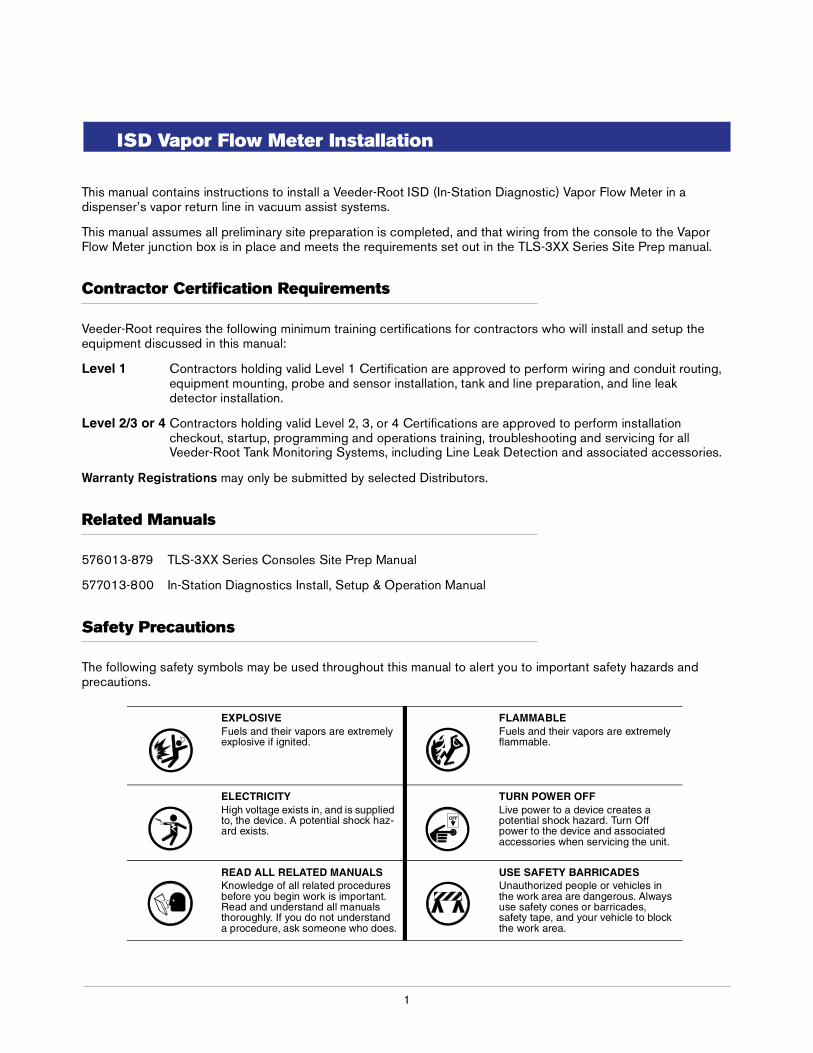
This manual contains instructions to install a Veeder-Root ISD (In-Station Diagnostic) Vapor Flow Meter in a dispenser’s vapor return line in vacuum assist systems.
This manual assumes all preliminary site preparation is completed, and that wiring from the console to the Vapor Flow Meter junction box is in place and meets the requirements set out in the TLS-3XX Series Site Prep manual.
Contractor Certification Requirements
Veeder-Root requires the following minimum training certifications for contractors who will install and setup the equipment discussed in this manual:
Level 1 Contractors holding valid Level 1 Certification are approved to perform wiring and conduit routing, equipment mounting, probe and sensor installation, tank and line preparation, and line leak detector installation.
Level 2/3 or 4 Contractors holding valid Level 2, 3, or 4 Certifications are approved to perform installation checkout, startup, programming and operations training, troubleshooting and servicing for all Veeder-Root Tank Monitoring Systems, including Line Leak Detection and associated accessories.
Warranty Registrations may only be submitted by selected Distributors.
Related Manuals
576013-879 TLS-3XX Series Consoles Site Prep Manual
577013-800 In-Station Diagnostics Install, Setup & Operation Manual
Safety Precautions
The following safety symbols may be used throughout this manual to alert you to important safety hazards and precautions.
EXPLOSIVEFuels and their vapors are extremely explosive if ignited.
FLAMMABLEFuels and their vapors are extremely flammable.
ELECTRICITYHigh voltage exists in, and is supplied to, the device. A potential shock haz-ard exists.
TURN POWER OFFLive power to a device creates a potential shock hazard. Turn Off power to the device and associated accessories when servicing the unit.
READ ALL RELATED MANUALSKnowledge of all related procedures before you begin work is important. Read and understand all manuals thoroughly. If you do not understand a procedure, ask someone who does.
USE SAFETY BARRICADESUnauthorized people or vehicles in the work area are dangerous. Always use safety cones or barricades, safety tape, and your vehicle to block the work area.
OFF
ISD Flow Meter Installation Guide Before You Begin
2
Before You Begin
• A level 1 or higher certified Veeder-Root Technician must be available (on site) to assist in this type of installation.
• Comply with all recommended safety practices identified by OSHA (Occupational Safety and Health Administration) and your employer.
• Follow all installation requirements as per NFPA (National Fire Protection Association) 30, 30A, and 70.
• Review and comply with all the safety warnings in the installation manuals and any other national, State or Local requirements.
• A 2-conductor, 18 AWG shielded cable must be installed in intrinsically safe conduit from each dispenser to the intrinsically safe wiring compartment of the TLS console.
• Debris from plumbing modifications should be flushed through the piping system prior to installing the ISD Vapor Flow Meter.
• Use only UL recognized Gas/TFE yellow teflon tape on all fittings. Do not use pipe dope to seal pipe threads or fittings in and out of the ISD Vapor Flow Meter.
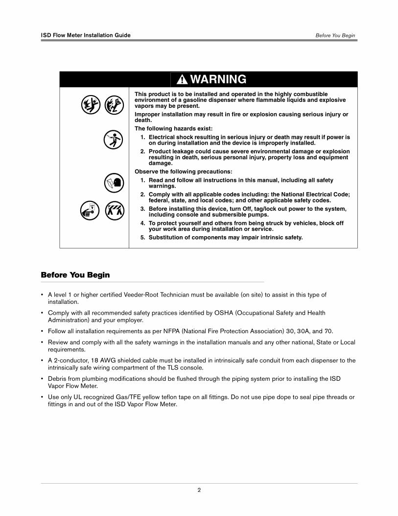
WARNINGThis product is to be installed and operated in the highly combustible environment of a gasoline dispenser where flammable liquids and explosive vapors may be present.Improper installation may result in fire or explosion causing serious injury or death.The following hazards exist:
1. Electrical shock resulting in serious injury or death may result if power is on during installation and the device is improperly installed.
2. Product leakage could cause severe environmental damage or explosion resulting in death, serious personal injury, property loss and equipment damage.
Observe the following precautions:1. Read and follow all instructions in this manual, including all safety
warnings.2. Comply with all applicable codes including: the National Electrical Code;
federal, state, and local codes; and other applicable safety codes. 3. Before installing this device, turn Off, tag/lock out power to the system,
including console and submersible pumps. 4. To protect yourself and others from being struck by vehicles, block off
your work area during installation or service.5. Substitution of components may impair intrinsic safety.
OFF
ISD Flow Meter Installation Guide Veeder-Root Parts
3
Veeder-Root Parts
• Veeder-Root ISD Vapor Flow Meter (P/N 331847-001).
• Sensor Installation Kit, see Table 1.
Tools Required
1. Pipe wrench suitable for tightening 1-inch NPT pipe.
2. 1/2’’ socket wrench to install Vapor Flow Meter flange bolts.
3. Necessary pipe fitter’s equipment and a non-hazardous work space suitable to modify dispenser vapor line for Vapor Flow Meter installation, when necessary.
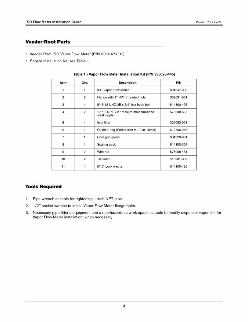
Table 1.- Vapor Flow Meter Installation Kit (P/N 330020-445)
Item Qty. Description P/N
1 1 ISD Vapor Flow Meter 331847-002
2 2 Flange with 1” NPT threaded hole 332091-001
3 4 5/16-18 UNC-2B x 3/4” hex head bolt 514100-426
4 2 1-11.5 NPT x 2 “ male to male threaded steel nipple
576008-655
5 1 Inlet filter 332092-001
6 1 Outlet o-ring (Parker size # 2-218, Nitrile) 512700-258
7 1 Cord grip group 331028-001
8 1 Sealing pack 514100-304
9 2 Wire nut 576008-461
10 2 Tie wrap 510901-337
11 4 5/16” Lock washer 514100-436

ISD Flow Meter Installation Guide Installation Steps - Vacuum Assist System Above Shear Valve
4
Installation Steps - Vacuum Assist System Above Shear Valve
1. Before installing this device, turn Off, tag/lock out power to the system, including console and submersible pumps.
2. Remove the dispenser’s lower sheet metal doors to access the vapor plumbing.
3. Loosen any factory installed mounts and/or brackets necessary to provide room to disconnect the vacuum motor outlet plumbing.
4. Disconnect the factory installed plumbing between the outlet of the vacuum motors and the field installed plumbing above the vapor shear valve, if present (see example installation in Figure 1). Retain the manufacturers installed piping for later use.
5. Remove any unneeded field installed plumbing above the vapor shear valve. The Vapor Flow Meter with flanges attached can be used for sizing the required head space of approximately 8 inches. Approximately 3 inches of clearance is required on both sides of the piping to accommodate the width of the meter body.
6. Working through the vacuum motor mounting plate, if present, connect the upper flange to factory installed plumbing. Note that this may need to be temporarily suspended across the vacuum motor mounting plate while the lower plumbing work progresses.
7. Install any plumbing and the lower flange that will connect between the outlet side of the Vapor Flow Meter and the shear valve or lower vapor return line. Note: Elbows should be kept to a minimum (straight vertical plumbing is preferable). To improve efficiency and to reduce the risk of liquid traps, all horizontal plumbing must be pitched to drain.
8. Clean all debris around the inlet and outlet plumbing prior to installing the Vapor Flow Meter. Do not blow compressed air through the Vapor Flow Meter to prevent damaging the internal screens.
9. Install the o-ring into the lower mounting flange.
10. Taking care that foreign material (chips, debris, sealant, etc.) does not enter the open piping or Vapor Flow Meter, carefully insert the inlet filter and then connect the Vapor Flow Meter to the upper flange. Note that the flow arrow on the side of the meter body must point down.
11. Connect the lower flange to the Vapor Flow Meter.
12. Tighten any loose fittings and hardware
13. Route the wiring into the junction box via the supplied cord grip assembly.
14. Connect the wires from the Vapor Flow Meter to the field wiring from the console and cap with wire nuts (see Figure 2).
15. After all other ISD Vapor Flow Meters and the ISD Pressure Sensor are installed, pressurize the tank ullage space and vapor piping to at least 2 inches WC and test for leaks using leak detection solution.
OFF
ISD Flow Meter Installation Guide Installation Steps - Vacuum Assist System Above Shear Valve
5
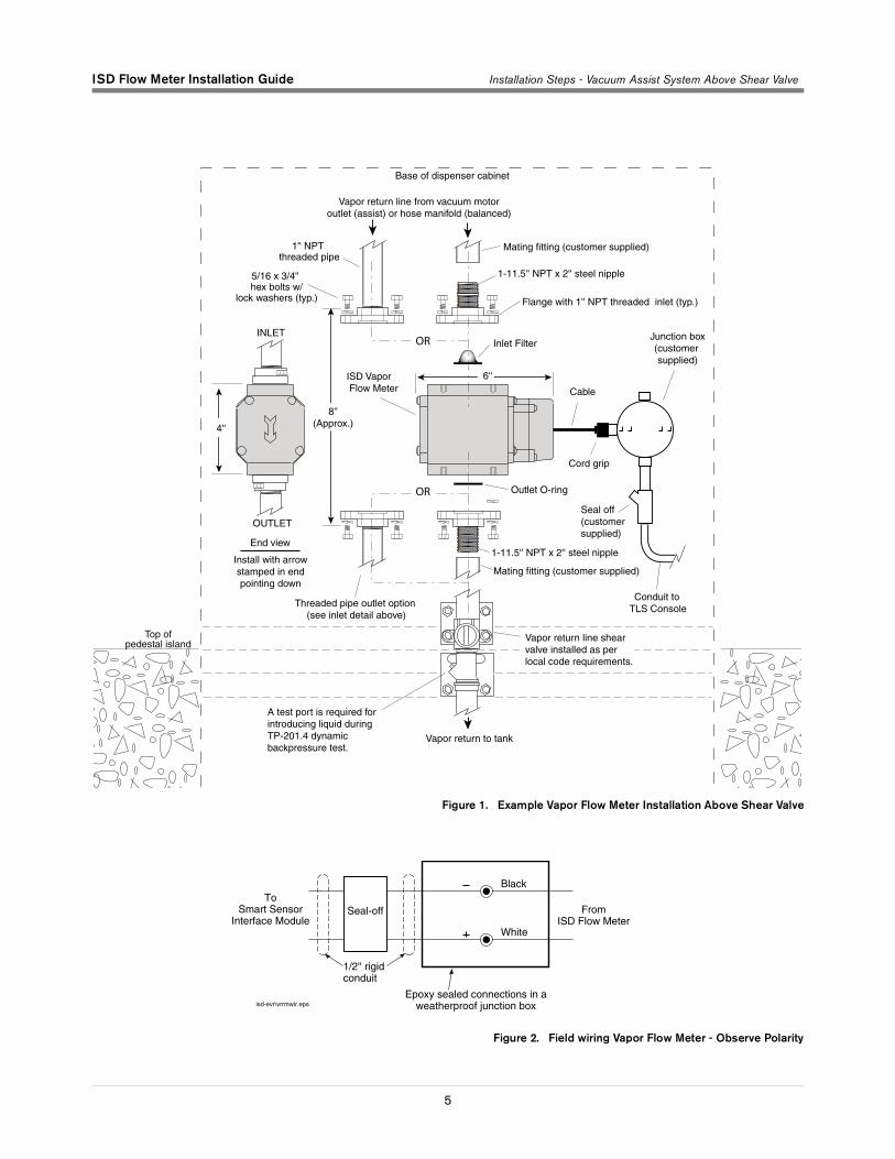
Figure 1. Example Vapor Flow Meter Installation Above Shear Valve
Figure 2. Field wiring Vapor Flow Meter - Observe Polarity
ISD Vapor Flow Meter
Conduit to TLS Console
Seal off(customersupplied)
Junction box(customer supplied)
Vapor return line from vacuum motoroutlet (assist) or hose manifold (balanced)
Vapor return to tank
End view
Install with arrowstamped in endpointing down
Cable
Cord grip
Base of dispenser cabinet
OR
OR
1'' NPT threaded pipe
Mating fitting (customer supplied)
1-11.5'' NPT x 2'' steel nipple
Flange with 1'' NPT threaded inlet (typ.)
Inlet Filter
Outlet O-ring
Threaded pipe outlet option (see inlet detail above)
OUTLET
INLET
8''(Approx.)4''
6''
Mating fitting (customer supplied)
1-11.5'' NPT x 2'' steel nipple
5/16 x 3/4'' hex bolts w/
lock washers (typ.)
Top ofpedestal island
Vapor return line shear valve installed as per local code requirements.
A test port is required for introducing liquid during TP-201.4 dynamicbackpressure test.
Black
White
ToSmart Sensor
Interface ModuleFrom
ISD Flow Meter
Epoxy sealed connections in aweatherproof junction box
1/2'' rigidconduit
Seal-off
isd-evr\vrrmwir.eps
ISD Flow Meter Installation Guide Installation Steps - Vacuum Assist System Below Shear Valve
6
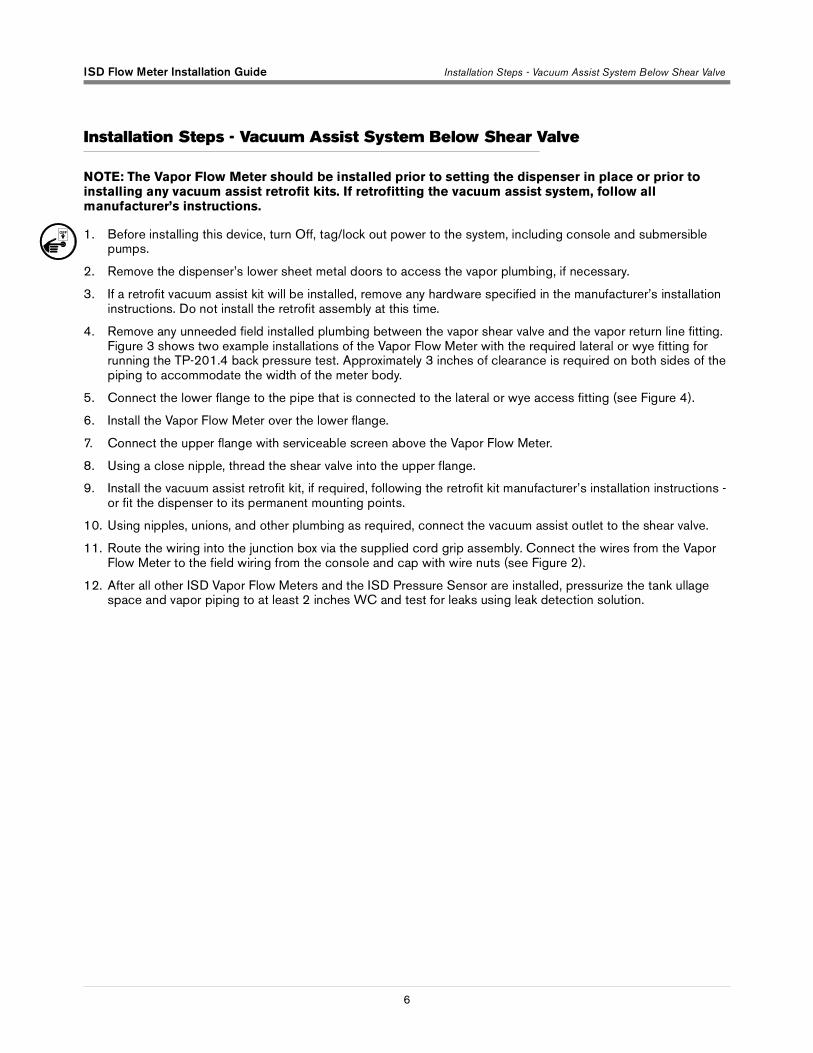
Installation Steps - Vacuum Assist System Below Shear Valve
NOTE: The Vapor Flow Meter should be installed prior to setting the dispenser in place or prior to installing any vacuum assist retrofit kits. If retrofitting the vacuum assist system, follow all manufacturer’s instructions.
1. Before installing this device, turn Off, tag/lock out power to the system, including console and submersible pumps.
2. Remove the dispenser’s lower sheet metal doors to access the vapor plumbing, if necessary.
3. If a retrofit vacuum assist kit will be installed, remove any hardware specified in the manufacturer’s installation instructions. Do not install the retrofit assembly at this time.
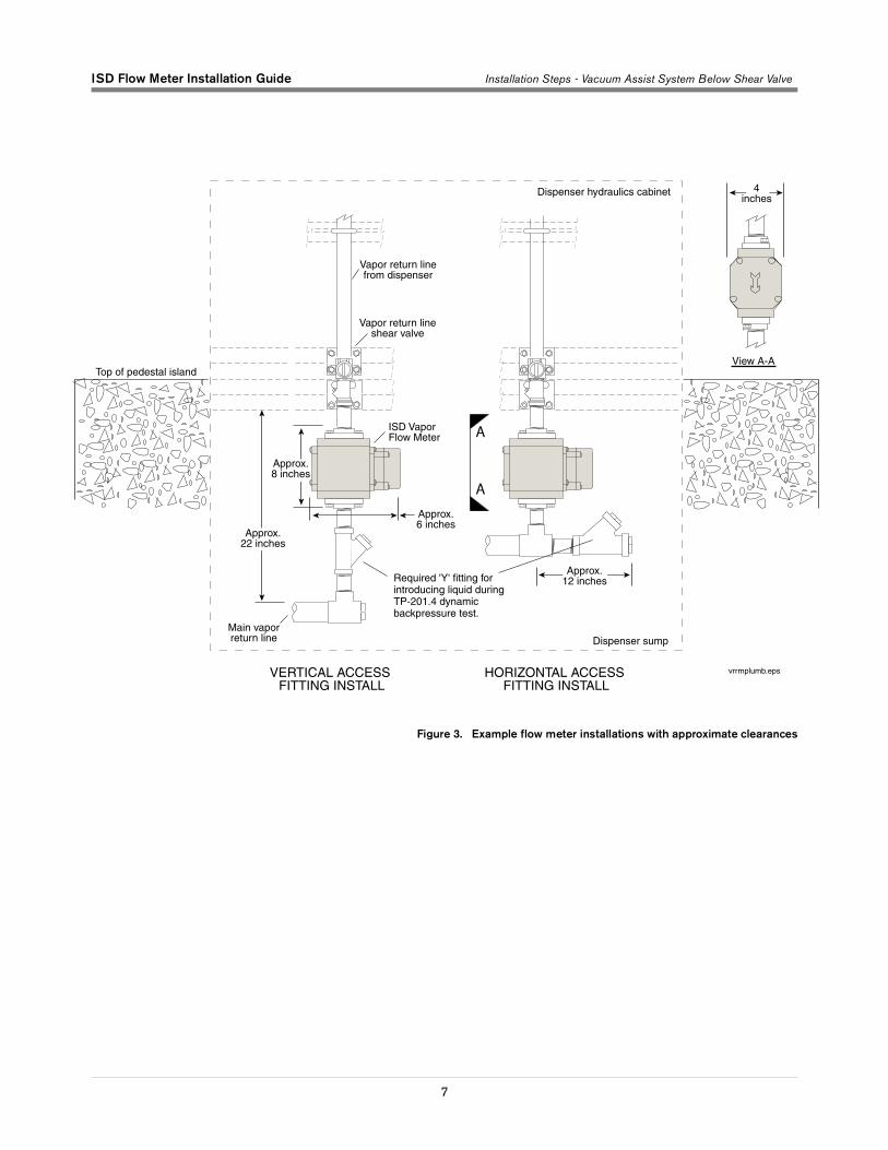
4. Remove any unneeded field installed plumbing between the vapor shear valve and the vapor return line fitting. Figure 3 shows two example installations of the Vapor Flow Meter with the required lateral or wye fitting for running the TP-201.4 back pressure test. Approximately 3 inches of clearance is required on both sides of the piping to accommodate the width of the meter body.
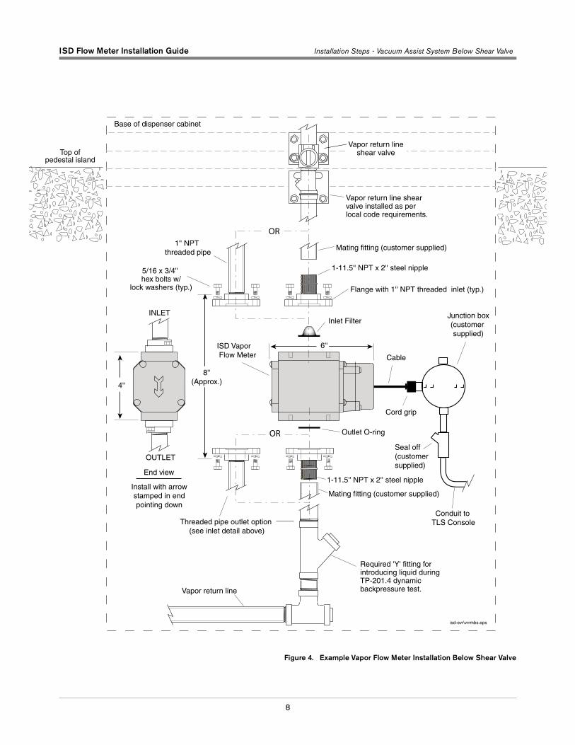
5. Connect the lower flange to the pipe that is connected to the lateral or wye access fitting (see Figure 4).
6. Install the Vapor Flow Meter over the lower flange.
7. Connect the upper flange with serviceable screen above the Vapor Flow Meter.
8. Using a close nipple, thread the shear valve into the upper flange.
9. Install the vacuum assist retrofit kit, if required, following the retrofit kit manufacturer’s installation instructions - or fit the dispenser to its permanent mounting points.
10. Using nipples, unions, and other plumbing as required, connect the vacuum assist outlet to the shear valve.
11. Route the wiring into the junction box via the supplied cord grip assembly. Connect the wires from the Vapor Flow Meter to the field wiring from the console and cap with wire nuts (see Figure 2).
12. After all other ISD Vapor Flow Meters and the ISD Pressure Sensor are installed, pressurize the tank ullage space and vapor piping to at least 2 inches WC and test for leaks using leak detection solution.
OFF
ISD Flow Meter Installation Guide Installation Steps - Vacuum Assist System Below Shear Valve
7
Figure 3. Example flow meter installations with approximate clearances
Main vaporreturn line
ISD Vapor Flow Meter
Vapor return lineshear valve
Vapor return linefrom dispenser
Dispenser hydraulics cabinet
Top of pedestal island
Dispenser sump
VERTICAL ACCESS FITTING INSTALL
HORIZONTAL ACCESS FITTING INSTALL
Approx.12 inches
Approx.22 inches
Approx.8 inches
Approx.6 inches
View A-A
vrrmplumb.eps
A
A
4inches
Required 'Y' fitting for introducing liquid duringTP-201.4 dynamic backpressure test.
ISD Flow Meter Installation Guide Installation Steps - Vacuum Assist System Below Shear Valve
8
Figure 4. Example Vapor Flow Meter Installation Below Shear Valve
ISD Vapor Flow Meter
Conduit to TLS Console
Seal off(customersupplied)
Junction box(customer supplied)
Vapor return line
End view
Install with arrowstamped in endpointing down
Cable
Cord grip
Base of dispenser cabinet
isd-evr\vrrmbs.eps
OR
OR
1'' NPT threaded pipe
Mating fitting (customer supplied)
1-11.5'' NPT x 2'' steel nipple
Flange with 1'' NPT threaded inlet (typ.)
Inlet Filter
Outlet O-ring
5/16 x 3/4'' hex bolts w/
lock washers (typ.)
Threaded pipe outlet option (see inlet detail above)
OUTLET
INLET
8''(Approx.)4''
6''
Mating fitting (customer supplied)
1-11.5'' NPT x 2'' steel nipple
Vapor return line shear valve installed as per local code requirements.
Top ofpedestal island
Required 'Y' fitting for introducing liquid duringTP-201.4 dynamic backpressure test.
Vapor return lineshear valve
ISD Flow Meter Installation Guide Seal and Connect Field Wiring
9
Seal and Connect Field Wiring
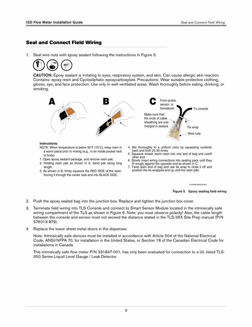
1. Seal wire nuts with epoxy sealant following the instructions in Figure 5.
CAUTION: Epoxy sealant is irritating to eyes, respiratory system, and skin. Can cause allergic skin reaction. Contains: epoxy resin and Cycloaliphatic epoxycarboxylate. Precautions: Wear suitable protective clothing, gloves, eye, and face protection. Use only in well ventilated areas. Wash thoroughly before eating, drinking, or smoking.
Figure 5. Epoxy sealing field wiring
2. Push the epoxy sealed bag into the junction box. Replace and tighten the junction box cover.
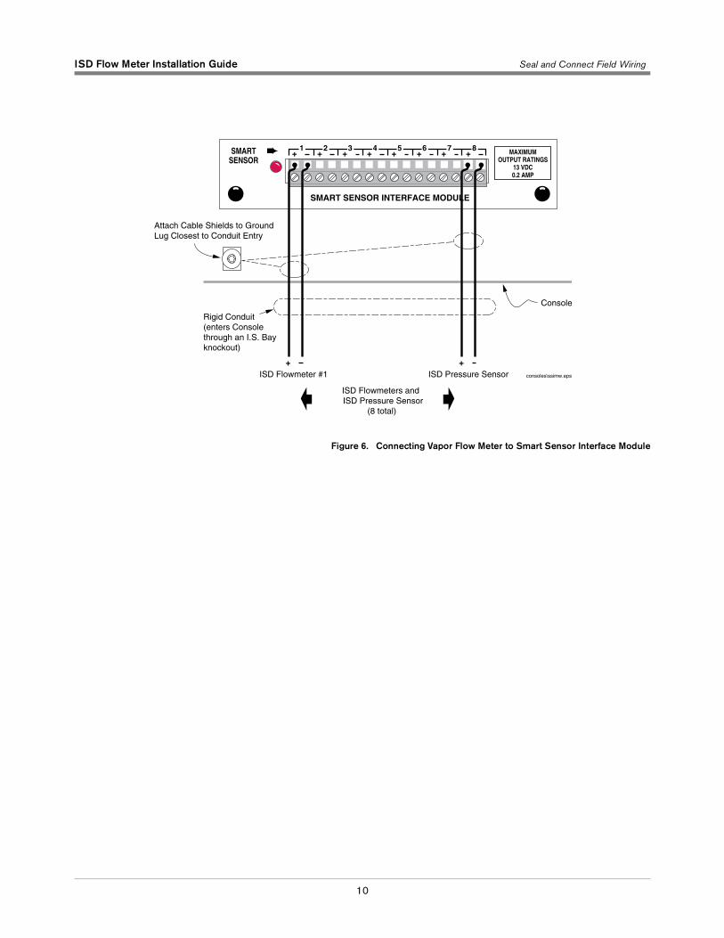
3. Terminate field wiring into TLS Console and connect to Smart Sensor Module located in the intrinsically safe wiring compartment of the TLS as shown in Figure 6. Note: you must observe polarity! Also, the cable length between the console and sensor must not exceed the distance stated in the TLS-3XX Site Prep manual (P/N 576013-879).
4. Replace the lower sheet metal doors in the dispenser.
Note: Intrinsically safe devices must be installed in accordance with Article 504 of the National Electrical Code, ANSI/NFPA 70, for installation in the United States, or Section 18 of the Canadian Electrical Code for installations in Canada.
This intrinsically safe flow meter P/N 331847-001, has only been evaluated for connection to a UL listed TLS-350 Series Liquid Level Gauge / Leak Detector.
consoles\epxy2w.eps
Instructions:NOTE: When temperature is below 50˚F (10˚C), keep resin in
a warm place prior to mixing (e.g., in an inside pocket next to body).
1. Open epoxy sealant package, and remove resin pak.2. Holding resin pak as shown in A, bend pak along long
length.3. As shown in B, firmly squeeze the RED SIDE of the resin,
forcing it through the center seal and into BLACK SIDE.
To console
Tie wrap
Wire nuts
From probe,sensor, ortransducer
A CBMake sure that the ends of cable sheathing are sub-merged in sealant
4. Mix thoroughly to a uniform color by squeezing contents back and forth 25-30 times.
5. Squeeze mixed, warm resin into one end of bag and cutoff other end.
6. Slowly insert wiring connections into sealing pack until they fit snugly against the opposite end as shown in C.
7. Twist open end of bag and use tie wrap to close it off and position the tie wrapped end up until the resin jells.
ISD Flow Meter Installation Guide Seal and Connect Field Wiring
10
Figure 6. Connecting Vapor Flow Meter to Smart Sensor Interface Module
Attach Cable Shields to Ground Lug Closest to Conduit Entry
SMARTSENSOR
MAXIMUMOUTPUT RATINGS
13 VDC0.2 AMP
+ + + + + + + +1 2 3 4 5 6 7 8
SMART SENSOR INTERFACE MODULE
consoles\ssimw.eps
Console
+ISD Flowmeter #1 ISD Pressure Sensor
+
ISD Flowmeters and ISD Pressure Sensor
(8 total)
Rigid Conduit(enters Consolethrough an I.S. Bay knockout)
Australia20 Highgate StreetAuburn, NSW, 2144Tel: +61 (0)2 8737 7777Fax: +61 (0)2 9737 9332Email: [email protected]
BrasilRua ado Benatti, 92Sao Paulo - SP 05037-904Tel: +55 (0) 11 3879 6600Fax: +55 (0) 11 3611 1982Email: [email protected]
CanadaEastern CanadaTel: (519) 925-9899Western CanadaTel: (604) 576-4469Email: [email protected]
ChinaRoom 2202, Scitech TowerNo. 22 Jian Guomen Wai DaJieBeijing 100004Tel: +86 10 6512 8081Fax: +86 10 6522 0887Email: lu [email protected]
EnglandHydrex House, Garden RoadRichmond, Surrey TW9 4NRTel: +44 (0) 20 8392 1355Fax: +44 (0) 20 8878 6642Email: [email protected]
France94, rue Blaise Pascal, ZI des Mardelles93600 Aulnay-Sous-BoisTel: +33 (0) 1 48 79 55 90Fax: +33 (0) 1 48 68 39 00Email: [email protected]
GermanyFerdinand-Henze-Straße 9, D-33154 SalzkottenTel: +49 (0)52 58 130 Fax: +49 (0)52 58 131 07Email: [email protected]
ItalyVia de’Cattani, 220/G, 50145 Firenze Tel: +39 (0)55 30941 Fax: +39 (0)55 318603Email: [email protected]
MexicoSagitario #4529-3Col. La Calma C.P. 45070Zapopan, JaliscoTel: (523) 632 3482Fax: (523) 133 3219Email: [email protected]
Poland01-517 Warszawa ul. Mickiewicza 18/12Tel/Fax: +48 (0)22 839 0847Email: [email protected]
Singapore246 MacPherson Road#08-01 Betime Building348578 Tel: +65 (0) 6745 9265Fax: +65 (0) 6745 1791Email: francis [email protected]
Headquarters125 Powder Forest DriveSimsbury, CT 06070-7684Tel: (860) 651-2700Fax: (860) 651-2719Email: [email protected]
www.veeder.com