isd vapor flow meter - california air resources board vapor flow meter installation contractor...
TRANSCRIPT
Manual No: 577013-796 Revision: E
Installation Guide
ISD Vapor Flow Meter

Notice
Veeder-Root makes no warranty of any kind with regard to this publication, including, but not limited to, the
implied warranties of merchantability and fitness for a particular purpose.
Veeder-Root shall not be liable for errors contained herein or for incidental or consequential damages in
connection with the furnishing, performance, or use of this publication.
Veeder-Root reserves the right to change system options or features, or the information contained in this
publication.
This publication contains proprietary information which is protected by copyright. All rights reserved. No part
of this publication may be photocopied, reproduced, or translated to another language without the prior writtenconsent of Veeder-Root.
DAMAGE CLAIMS
1. Thoroughly examine all components and units as soon as they are received. If damaged, write a complete
and detailed description of the damage on the face of the freight bill. The carrier's agent must verify the
inspection and sign the description.
2. Immediately notify the delivering carrier of damage or loss. This notification may be given either in person
or by telephone. Written confirmation must be mailed within 48 hours. Railroads and motor carriers are
reluctant to make adjustments for damaged merchandise unless inspected and reported promptly.
3. Risk of loss, or damage to merchandise remains with the buyer. It is the buyer's responsibility to file a claim
with the carrier involved.
RETURN SHIPPING
For the parts return procedure, please follow the appropriate instructions in the "General Returned Goods
Policy" and "Parts Return" pages in the "Policies and Literature" section of the Veeder-Root North American
Environmental Products price list.
©Veeder-Root 2005. All rights reserved.
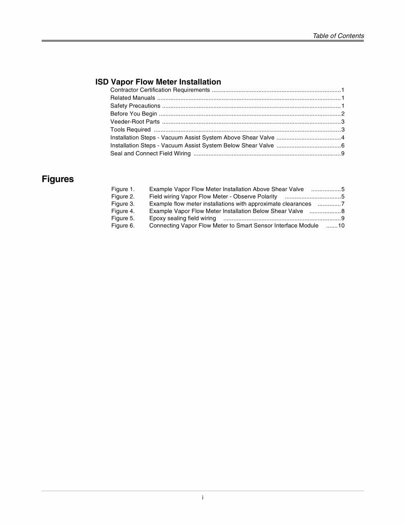
Table of Contents
i
Table of Contents
ISD Vapor Flow Meter InstallationContractor Certification Requirements ..............................................................................1
Related Manuals ...............................................................................................................1
Safety Precautions ............................................................................................................1
Before You Begin ..............................................................................................................2
Veeder-Root Parts ............................................................................................................3
Tools Required .................................................................................................................3
Installation Steps - Vacuum Assist System Above Shear Valve .......................................4
Installation Steps - Vacuum Assist System Below Shear Valve .......................................6
Seal and Connect Field Wiring .........................................................................................9
FiguresFigure 1. Example Vapor Flow Meter Installation Above Shear Valve ..................5
Figure 2. Field wiring Vapor Flow Meter - Observe Polarity ..................................5
Figure 3. Example flow meter installations with approximate clearances ..............7
Figure 4. Example Vapor Flow Meter Installation Below Shear Valve ...................8
Figure 5. Epoxy sealing field wiring .......................................................................9
Figure 6. Connecting Vapor Flow Meter to Smart Sensor Interface Module .......10

1
ISD Vapor Flow Meter Installation
This manual contains instructions to install a Veeder-Root ISD (In-Station Diagnostic) Vapor Flow Meter in a dispenser’s vapor return line in vacuum assist systems.
This manual assumes all preliminary site preparation is completed, and that wiring from the console to the Vapor Flow Meter junction box is in place and meets the requirements set out in the TLS-3XX Series Site Prep manual.
Contractor Certification Requirements
Veeder-Root requires the following minimum training certifications for contractors who will install and setup the equipment discussed in this manual:
Level 1 Contractors holding valid Level 1 Certification are approved to perform wiring and conduit routing, equipment mounting, probe and sensor installation, tank and line preparation, and line leak detector installation.
Level 2/3 or 4 Contractors holding valid Level 2, 3, or 4 Certifications are approved to perform installation checkout, startup, programming and operations training, troubleshooting and servicing for all Veeder-Root Tank Monitoring Systems, including Line Leak Detection and associated accessories.
Warranty Registrations may only be submitted by selected Distributors.
Related Manuals
576013-879 TLS-3XX Series Consoles Site Prep Manual
577013-800 In-Station Diagnostics Install, Setup & Operation Manual
Safety Precautions
The following safety symbols may be used throughout this manual to alert you to important safety hazards and precautions.
EXPLOSIVE
Fuels and their vapors are extremely explosive if ignited.
FLAMMABLE
Fuels and their vapors are extremely flammable.
ELECTRICITY
High voltage exists in, and is supplied to, the device. A potential shock haz-ard exists.
TURN POWER OFF
Live power to a device creates a potential shock hazard. Turn Off power to the device and associated accessories when servicing the unit.
READ ALL RELATED MANUALS
Knowledge of all related procedures before you begin work is important. Read and understand all manuals thoroughly. If you do not understand a procedure, ask someone who does.
USE SAFETY BARRICADES
Unauthorized people or vehicles in the work area are dangerous. Always use safety cones or barricades, safety tape, and your vehicle to block the work area.
OFF

ISD Flow Meter Installation Guide Before You Begin
2
Before You Begin
WARNINGThis product is to be installed and operated in the highly combustible environment of a gasoline dispenser where flammable liquids and explosive vapors may be present.
Improper installation may result in fire or explosion causing serious injury or death.
The following hazards exist:
1. Electrical shock resulting in serious injury or death may result if power is on during installation and the device is improperly installed.
2. Product leakage could cause severe environmental damage or explosion resulting in death, serious personal injury, property loss and equipment damage.
Observe the following precautions:
1. Read and follow all instructions in this manual, including all safety warnings.
2. Comply with all applicable codes including: the National Electrical Code; federal, state, and local codes; and other applicable safety codes.
3. Before installing this device, turn Off, tag/lock out power to the system, including console and submersible pumps.
4. To protect yourself and others from being struck by vehicles, block off your work area during installation or service.
5. Substitution of components may impair intrinsic safety.
OFF

ISD Flow Meter Installation Guide Veeder-Root Parts
3
Veeder-Root Parts
Tools Required
Table 1.- Vapor Flow Meter Installation Kit (P/N 330020-445)
Item Qty. Description P/N
1 1 ISD Vapor Flow Meter 331847-002
2 2 Flange with 1” NPT threaded hole 332091-001
3 4 5/16-18 UNC-2B x 3/4” hex head bolt 514100-426
4 2 1-11.5 NPT x 2 “ male to male threaded steel nipple
576008-655
5 1 Inlet filter 332092-001
6 1 Outlet o-ring (Parker size # 2-218, Nitrile) 512700-258
7 1 Cord grip group 331028-001
8 1 Sealing pack 514100-304
9 2 Wire nut 576008-461
10 2 Tie wrap 510901-337
11 4 5/16” Lock washer 514100-436

ISD Flow Meter Installation Guide Installation Steps - Vacuum Assist System Above Shear Valve
4
Installation Steps - Vacuum Assist System Above Shear Valve
1. Before installing this device, turn Off, tag/lock out power to the system, including console and submersible pumps.
2. Remove the dispenser’s lower sheet metal doors to access the vapor plumbing.
3. Loosen any factory installed mounts and/or brackets necessary to provide room to disconnect the vacuum motor outlet plumbing.
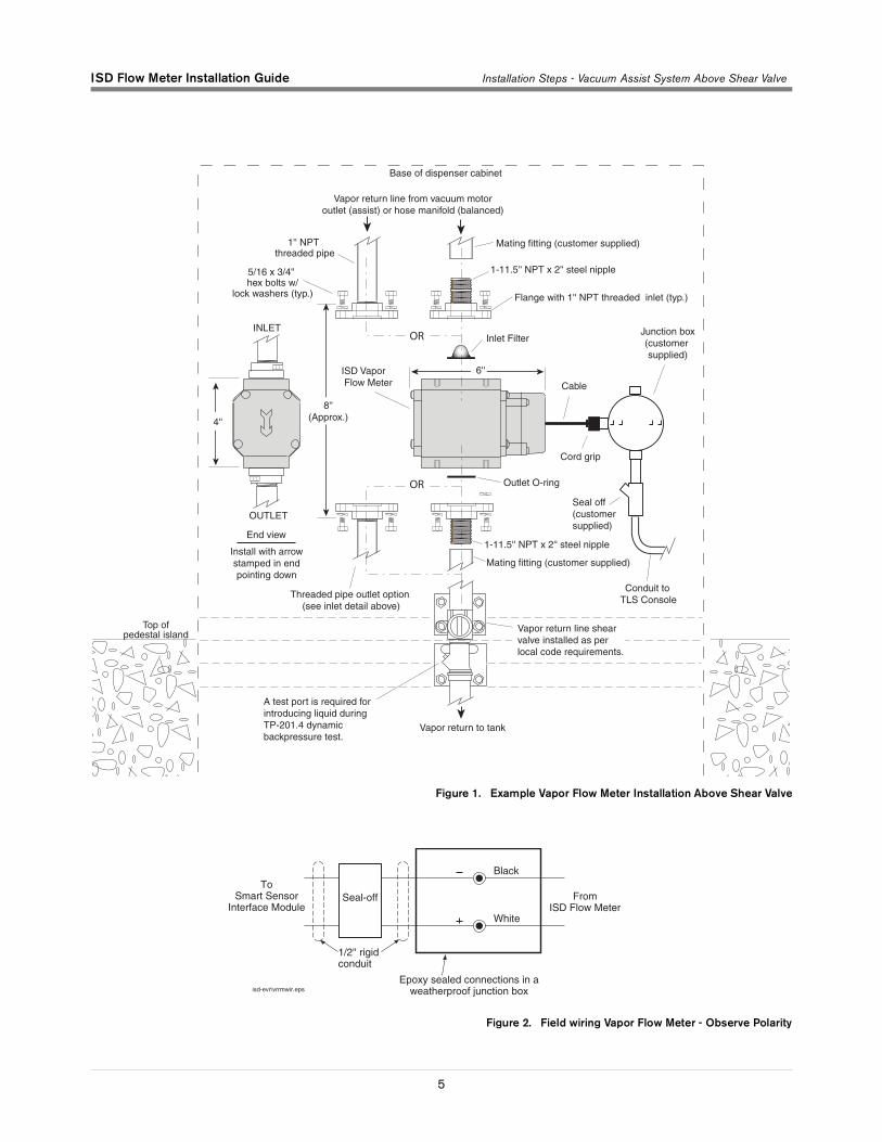
4. Disconnect the factory installed plumbing between the outlet of the vacuum motors and the field installed plumbing above the vapor shear valve, if present (see example installation in Figure 1). Retain the manufacturers installed piping for later use.
5. Remove any unneeded field installed plumbing above the vapor shear valve. The Vapor Flow Meter with flanges attached can be used for sizing the required head space of approximately 8 inches. Approximately 3 inches of clearance is required on both sides of the piping to accommodate the width of the meter body.
6. Working through the vacuum motor mounting plate, if present, connect the upper flange to factory installed plumbing. Note that this may need to be temporarily suspended across the vacuum motor mounting plate while the lower plumbing work progresses.
7. Install any plumbing and the lower flange that will connect between the outlet side of the Vapor Flow Meter and the shear valve or lower vapor return line. Note: Elbows should be kept to a minimum (straight vertical plumbing is preferable). To improve efficiency and to reduce the risk of liquid traps, all horizontal plumbing must be pitched to drain.
8. Clean all debris around the inlet and outlet plumbing prior to installing the Vapor Flow Meter. Do not blow compressed air through the Vapor Flow Meter to prevent damaging the internal screens.
9. Install the o-ring into the lower mounting flange.
10. Taking care that foreign material (chips, debris, sealant, etc.) does not enter the open piping or Vapor Flow Meter, carefully insert the inlet filter and then connect the Vapor Flow Meter to the upper flange. Note that the flow arrow on the side of the meter body must point down.
11. Connect the lower flange to the Vapor Flow Meter.
12. Tighten any loose fittings and hardware
13. Route the wiring into the junction box via the supplied cord grip assembly.
14. Connect the wires from the Vapor Flow Meter to the field wiring from the console and cap with wire nuts (see Figure 2).
15. After all other ISD Vapor Flow Meters and the ISD Pressure Sensor are installed, pressurize the tank ullage space and vapor piping to at least 2 inches WC and test for leaks using leak detection solution.
OFF
ISD Flow Meter Installation Guide Installation Steps - Vacuum Assist System Above Shear Valve
5
Figure 1. Example Vapor Flow Meter Installation Above Shear Valve
Figure 2. Field wiring Vapor Flow Meter - Observe Polarity
OR
OR
ISD Flow Meter Installation Guide Installation Steps - Vacuum Assist System Below Shear Valve
6
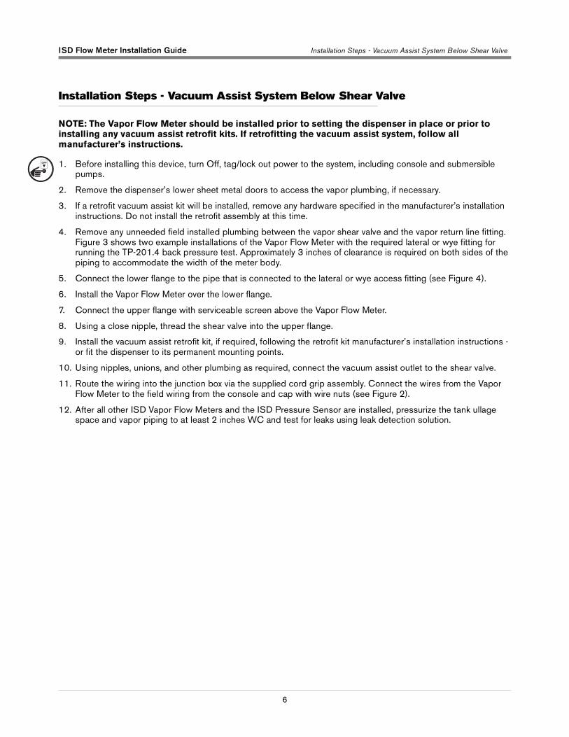
Installation Steps - Vacuum Assist System Below Shear Valve
NOTE: The Vapor Flow Meter should be installed prior to setting the dispenser in place or prior to installing any vacuum assist retrofit kits. If retrofitting the vacuum assist system, follow all manufacturer’s instructions.
1. Before installing this device, turn Off, tag/lock out power to the system, including console and submersible pumps.
2. Remove the dispenser’s lower sheet metal doors to access the vapor plumbing, if necessary.
3. If a retrofit vacuum assist kit will be installed, remove any hardware specified in the manufacturer’s installation instructions. Do not install the retrofit assembly at this time.
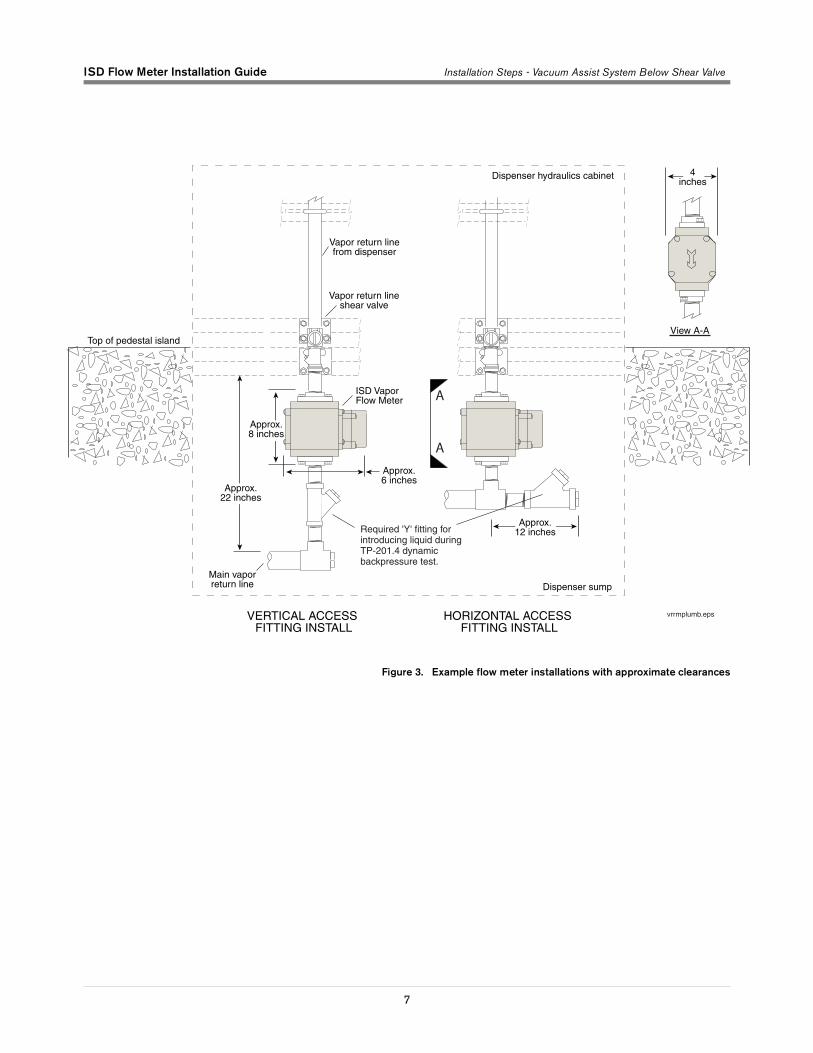
4. Remove any unneeded field installed plumbing between the vapor shear valve and the vapor return line fitting. Figure 3 shows two example installations of the Vapor Flow Meter with the required lateral or wye fitting for running the TP-201.4 back pressure test. Approximately 3 inches of clearance is required on both sides of the piping to accommodate the width of the meter body.
5. Connect the lower flange to the pipe that is connected to the lateral or wye access fitting (see Figure 4).
6. Install the Vapor Flow Meter over the lower flange.
7. Connect the upper flange with serviceable screen above the Vapor Flow Meter.
8. Using a close nipple, thread the shear valve into the upper flange.
9. Install the vacuum assist retrofit kit, if required, following the retrofit kit manufacturer’s installation instructions - or fit the dispenser to its permanent mounting points.
10. Using nipples, unions, and other plumbing as required, connect the vacuum assist outlet to the shear valve.
11. Route the wiring into the junction box via the supplied cord grip assembly. Connect the wires from the Vapor Flow Meter to the field wiring from the console and cap with wire nuts (see Figure 2).
12. After all other ISD Vapor Flow Meters and the ISD Pressure Sensor are installed, pressurize the tank ullage space and vapor piping to at least 2 inches WC and test for leaks using leak detection solution.
OFF
ISD Flow Meter Installation Guide Installation Steps - Vacuum Assist System Below Shear Valve
7
Figure 3. Example flow meter installations with approximate clearances
A
A

ISD Flow Meter Installation Guide Installation Steps - Vacuum Assist System Below Shear Valve
8
Figure 4. Example Vapor Flow Meter Installation Below Shear Valve
OR
OR

ISD Flow Meter Installation Guide Seal and Connect Field Wiring
9
Seal and Connect Field Wiring
1. Seal wire nuts with epoxy sealant following the instructions in Figure 5.
CAUTION: Epoxy sealant is irritating to eyes, respiratory system, and skin. Can cause allergic skin reaction. Contains: epoxy resin and Cycloaliphatic epoxycarboxylate. Precautions: Wear suitable protective clothing, gloves, eye, and face protection. Use only in well ventilated areas. Wash thoroughly before eating, drinking, or smoking.
Figure 5. Epoxy sealing field wiring
2. Push the epoxy sealed bag into the junction box. Replace and tighten the junction box cover.
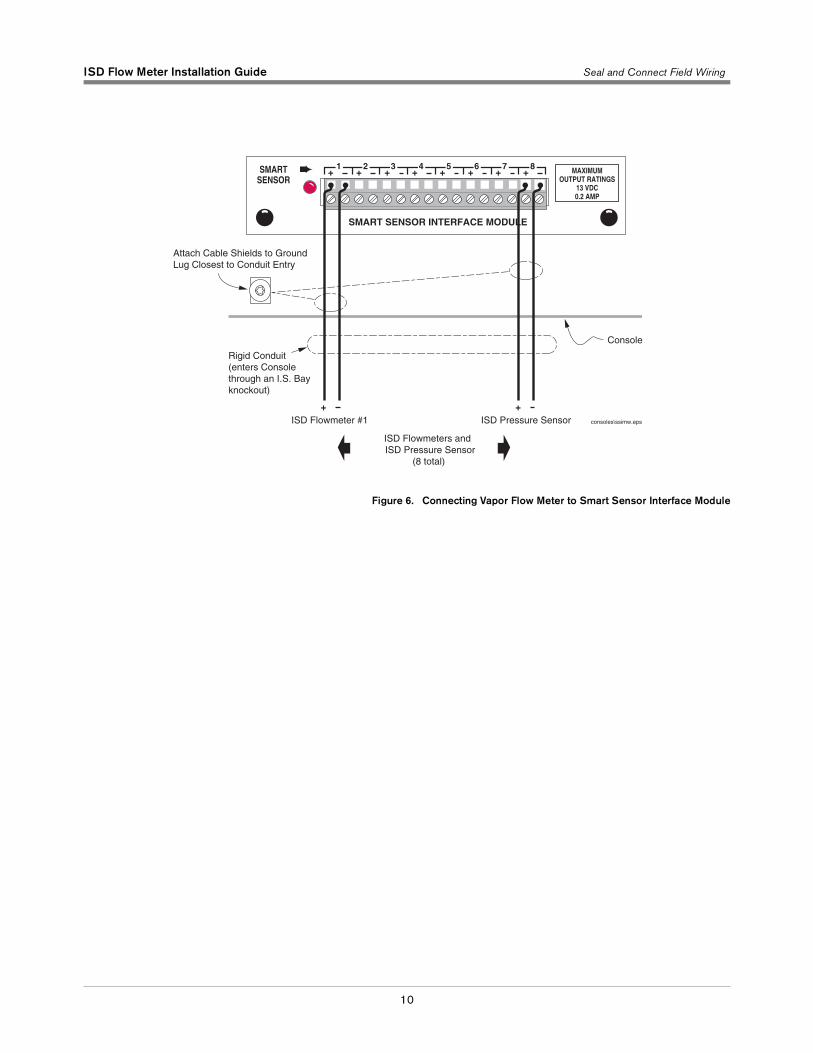
3. Terminate field wiring into TLS Console and connect to Smart Sensor Module located in the intrinsically safe wiring compartment of the TLS as shown in Figure 6. Note: you must observe polarity! Also, the cable length between the console and sensor must not exceed the distance stated in the TLS-3XX Site Prep manual (P/N 576013-879).
4. Replace the lower sheet metal doors in the dispenser.
Note: Intrinsically safe devices must be installed in accordance with Article 504 of the National Electrical Code, ANSI/NFPA 70, for installation in the United States, or Section 18 of the Canadian Electrical Code for installations in Canada.
This intrinsically safe flow meter P/N 331847-001, has only been evaluated for connection to a UL listed TLS-350 Series Liquid Level Gauge / Leak Detector.
A CB
ISD Flow Meter Installation Guide Seal and Connect Field Wiring
10
Figure 6. Connecting Vapor Flow Meter to Smart Sensor Interface Module
SMART
SENSOR
MAXIMUM
OUTPUT RATINGS
13 VDC
0.2 AMP
+ + + + + + + +1 2 3 4 5 6 7 8
SMART SENSOR INTERFACE MODULE
+ +
Australia
20 Highgate StreetAuburn, NSW, 2144Tel: +61 (0)2 8737 7777Fax: +61 (0)2 9737 9332Email: [email protected]
Brasil
Rua ado Benatti, 92Sao Paulo - SP 05037-904Tel: +55 (0) 11 3879 6600Fax: +55 (0) 11 3611 1982Email: [email protected]
Canada
Eastern CanadaTel: (519) 925-9899Western CanadaTel: (604) 576-4469Email: [email protected]
China
Room 2202, Scitech TowerNo. 22 Jian Guomen Wai DaJieBeijing 100004Tel: +86 10 6512 8081Fax: +86 10 6522 0887Email: lu [email protected]
England
Hydrex House, Garden RoadRichmond, Surrey TW9 4NRTel: +44 (0) 20 8392 1355Fax: +44 (0) 20 8878 6642Email: [email protected]
France
94, rue Blaise Pascal, ZI des Mardelles93600 Aulnay-Sous-BoisTel: +33 (0) 1 48 79 55 90Fax: +33 (0) 1 48 68 39 00Email: [email protected]
Germany
Ferdinand-Henze-Straße 9, D-33154 SalzkottenTel: +49 (0)52 58 130 Fax: +49 (0)52 58 131 07Email: [email protected]
Italy
Via de’Cattani, 220/G, 50145 Firenze Tel: +39 (0)55 30941 Fax: +39 (0)55 318603Email: [email protected]
Mexico
Sagitario #4529-3Col. La Calma C.P. 45070Zapopan, JaliscoTel: (523) 632 3482Fax: (523) 133 3219Email: [email protected]
Poland
01-517 Warszawa ul. Mickiewicza 18/12Tel/Fax: +48 (0)22 839 0847Email: [email protected]
Singapore
246 MacPherson Road#08-01 Betime Building348578 Tel: +65 (0) 6745 9265Fax: +65 (0) 6745 1791Email: francis [email protected]
Headquarters
125 Powder Forest DriveSimsbury, CT 06070-7684Tel: (860) 651-2700Fax: (860) 651-2719Email: [email protected]
www.veeder.com