island dreamer - crown yacht charterscrownyachtcharters.com/images/40baylinerops.pdfthank you for...
TRANSCRIPT

ISLAND DREAMEROPERATIONS MANUAL
Bayliner 4087
CrownCrown Yacht ChartersYacht Charters(Revision Date 6-16-16 ) (Revision Date 6-16-16 )

Table of Contents
SECTION TITLE Page
1 Introduction – About This Manual ……………. 4
2 Important Reminders ………………………….. 5
3 Operating Checklist ……………………………. 7
4 General Specifications / Engines / Fuel ………. 9
5 Operation of Vessel ……………………………. 11
6 Galley …………………………………………… 13
7 Heads / Plumbing ……………………………… 15
8 Cabin Heat …………………………………….. 17
9 Electrical ……………………………………….. 17
10 Inverter System ………………………………… 19
11 Electronics ……………………………………… 20
12 Trim Tabs ……………………………………… 21
13 Bilge Pumps ……………………………………. 21
14 Anchoring & Operation of Windlass …………. 21
15 Dinghy & Davits ……………………………….. 22
16 Miscellaneous …………………………………… 23
17 Securing …………………………………………. 24
18 “What to do If” …………………………………. 25
19 Emergency Procedures …………………………. 27
2
Welcome Aboard!
Thank you for choosing ISLAND DREAMER as your charter vessel. Please give her the respect and care she deserves while enjoying her many fine features. We will be more than happy to hear from you concerning suggestions to ensure your cruising satisfaction. Please read the following operations manual and the individual manuals aboard the boat that describe in detail the systems and accessories on the boat. Feel free to make recommendations for changes or additions (especially corrections) as your comments will ensure all information is understood and appropriate for all crews. The individual manuals can be found on the top shelf of the cabinet in the aft cabin (behind the sliding mirror door.) These manuals should be of assistance with troubleshooting if required. Please return the manuals to the cabinet when finished.
Once again, welcome aboard!
Helpful Phone Numbers
Crown Yacht Charters 1-800-426-2313 360-293-9533
3
Section 1: About This Manual
Manual Objective and Limitations
This manual is intended to introduce you to “Island Dreamer”, its systems and features, allowing you to operate it with the confidence and self-assurance necessary to enjoy your cruising vacation to its fullest. It is not intended to replace a basic understanding of seamanship, including navigation skills, weather interpretation or boat handling. You are expected to have an understanding of these subjects obtained through other sources, including training, seminars, reading and perhaps most important, experience.
There is no way that a small manual like this one can answer every question or give you a solution to every circumstance, foreseen or unforeseen. If you have a question which limits your understanding or handling of this vessel, ask your checkout skipper or contact the Crown Yacht Management office for details (you might make a list of questions as you read the manual, saving them all up to ask at one time).
How the Manual is Organized
Each section defines its general purpose as shown on the front page. You will use the section containing checklists, most of all. You should have it available so that each checklist can be used on a daily basis, even after you are familiar with the boat. Another copy of the checklists has been laminated and is stored in the inside back cover of the Ship’s Binder.
The Section regarding Emergency Procedures is the most important, and you should read it, but hopefully you will never need it.
Read this section first to learn about this manual and the general details of your boat. The other sections will tell you most of what you need to know to enjoy your cruise to the fullest with safety and confidence.
4

Section 2: Important Reminders
1. Under the law, YOU are in charge of the boat. You are expected to be familiar with good operating practices, no matter what you may have heard or read! If you are insecure with your knowledge about some procedure, check the manuals, "Chapman's", call Crown Yacht Charters or the Coast Guard (USCG).
2. Under the law, you MUST report to cus toms when crossing an inter national boundary . This is not treated casually by the authorities, and there are serious fines imposed on those who cannot prove they "checked in". Fill in the customs log.
3. Under the law, the master of a docu mented vessel is re quired to KEEP A LOG of the ship's use. This is not just a "diary" of what you did and who you saw! Should any adverse event occur, this log is treated with great credence by the courts, as long as it is "contemporaneous", i.e., filled out at the time of the event. Keep the ship's log!
4. Under the law, radio operations must follow proper procedures and be on correct chan - nels. See the section on Radio Procedures in your charter’s guide for a reminder of these if you are unsure!
5. Under your "Charter Insurance" that covers this boat, you cannot operate before sunrise or after sunset, nor in "restricted visibility" or in "gale force or higher" winds. If you have an accident and are not within these parameters of your insurance, you are liable and will not be covered by insurance.
6. Under the law, YOU cannot discharge untreated sewage from the head system in U.S. waters. This boat is equipped with two holding tank systems. Use them in U.S. waters! In addition, be sure the overboard valves are secured with a "wire ties" if in a no-discharge zone (east of the Hiram Chittenden Locks) in case the vessel is boarded for inspection by the Coast Guard.
7. Logs and debris are a hazard in our waterways! You must ALWAYS keep a lookout. If you hit a log, it is YOUR fault. Don’t run fast into the sunset or sunrise, as sparkles on the water hide flotsam. Debris will be pushed away from the hull when running slowly and avoid damage to the running gear. A careful lookout will avoid costly damage to the props and or shafts and worst of all potentially ruin a well planned and deserved vacation. If you do run fast, always operate the vessel from the upper helm.
8. If the fishermen are out, watch for nets! Nets are marked, often poorly, by a red ball at the end. The problem is, sometimes the balls are barely floating, and you often don't see the net until it's too late. Here's the best way to avoid a net: Slow down, and steer directly toward the fish ing boat . When you get nearer it, you should see the line of floats that support the top edge of the net --- that is, if the net is out!
9. You are responsible for your own wake. Please be courteous, and slow down, especially in narrow passages and in harbors. Look behind your boat, and imagine crossing your own wake in a small boat: How would you like it? Imagine having your lunch dumped off the table by a passing boat like yours!
5
Section 3: Operating Checklist – Island Dreamer
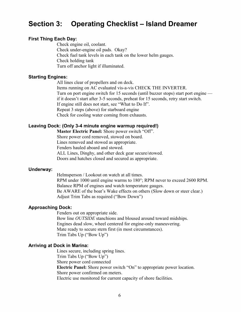
First Thing Each Day:Check engine oil, coolant. Check under-engine oil pads. Okay?Check fuel tank levels in each tank on the lower helm gauges.Check holding tank Turn off anchor light if illuminated.
Starting Engines:All lines clear of propellers and on deck.Items running on AC evaluated vis-a-vis CHECK THE INVERTER.Turn on port engine switch for 15 seconds (until buzzer stops) start port engine — if it doesn’t start after 3-5 seconds, preheat for 15 seconds, retry start switch.If engine still does not start, see “What to Do If”.Repeat 3 steps (above) for starboard engineCheck for cooling water coming from exhausts.
Leaving Dock: (Only 3-4 minute engine warmup required!)Master Electric Panel: Shore power switch “Off”.Shore power cord removed, stowed on board.Lines removed and stowed as appropriate.Fenders hauled aboard and stowed.ALL Lines, Dinghy, and other deck gear secure/stowed.Doors and hatches closed and secured as appropriate.
Underway:Helmsperson / Lookout on watch at all times.RPM under 1000 until engine warms to 180°; RPM never to exceed 2600 RPM.Balance RPM of engines and watch temperature gauges.
Be AWARE of the boat’s Wake effects on others (Slow down or steer clear.)Adjust Trim Tabs as required (“Bow Down”)
Approaching Dock:Fenders out on appropriate side.Bow line OUTSIDE stanchions and bloused around toward midships.Engines dead slow, wheel centered for engine-only maneuvering.Mate ready to secure stern first (in most circumstances).Trim Tabs Up (“Bow Up”)
Arriving at Dock in Marina:Lines secure, including spring lines.Trim Tabs Up (“Bow Up”)Shore power cord connectedElectric Panel: Shore power switch “On” to appropriate power location.Shore power confirmed on meters.Electric use monitored for current capacity of shore facilities.
6
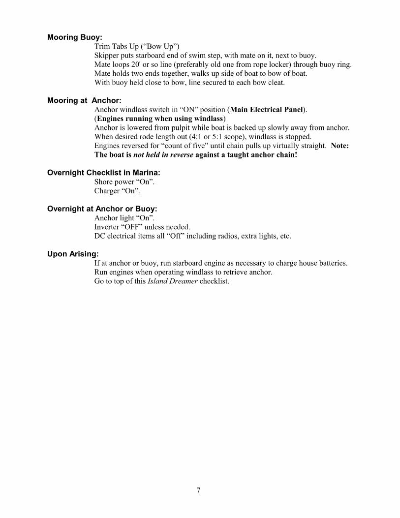
Mooring Buoy:Trim Tabs Up (“Bow Up”)Skipper puts starboard end of swim step, with mate on it, next to buoy.Mate loops 20' or so line (preferably old one from rope locker) through buoy ring.Mate holds two ends together, walks up side of boat to bow of boat.With buoy held close to bow, line secured to each bow cleat.
Mooring at Anchor:Anchor windlass switch in “ON” position (Main Electrical Panel).(Engines running when using windlass)Anchor is lowered from pulpit while boat is backed up slowly away from anchor. When desired rode length out (4:1 or 5:1 scope), windlass is stopped.Engines reversed for “count of five” until chain pulls up virtually straight. Note: The boat is not held in reverse against a taught anchor chain!
Overnight Checklist in Marina:Shore power “On”.Charger “On”.
Overnight at Anchor or Buoy:Anchor light “On”.Inverter “OFF” unless needed.DC electrical items all “Off” including radios, extra lights, etc.
Upon Arising:If at anchor or buoy, run starboard engine as necessary to charge house batteries.Run engines when operating windlass to retrieve anchor.Go to top of this Island Dreamer checklist.
7

Section 4: General Specifications / Engines / Fuel
A. Specifications
LOA 41’ 5” (including swim step & bow pulpit)
LWL 37’ 9”
Beam 13’ 11”
Draft 3’ 9” (HULL 2’ 8”)
Bridge Clearance 15’ 5”
Displacement 24,000 Lbs
Water 77 gallons + 11 gallon in hot water tank
Holding Tanks 66 gallons (33 gallons (fwd) + 33 gallons (aft))
Engines Twin Cummins Diesel - 250 HP
Fuel 220 gallons, #2 Diesel (110 PORT + 110 STBD)
Engine Motor Oil 15W – 40W Chevron Delo Multigrade
Transmission Oil: SAE 30 Weight Chevron Delo 100
Engine Coolant: 50-50 mix, ethylene glycol and water; corrosion
inhibitor added
Operating Parameters: 1400 RPM 11.0 Knots 7.5 GPH
2200 RPM 17.0 knots 14.5 GPH
(All estimated fully loaded) 2600 RPM 20.0 knots 25.0 GPH (Max Cruise RPM)
Placard locations: MARPOL placard: On front cabinet door above microwave
OIL SPILLS placard: Inside engine room entrance
B. Vessel Important Numbers
Vessel Official Number: (None)
Vessel U.S. Customs Permit Number: Refer to (Island Dreamer) Binder
USCG Vessel Registration Number: USCG DOC 1201586
FCC Ships License Call Letters:
Washington Parks Permit Number: Refer to (Island Dreamer) Binder
Hull ID Number: BLBA 03ETH697
8

C. Safety Equipment
1. FIRE EXTINGUISHERS- 4 Onboard: One mounted by the stairs into the salon adjacent to the entry to the aft cabin, one located in the aft cabin on the port side of the back wall, one located at the lower helm on the lower right side, and one located adjacent to the closet door in the mid cabin.
2. LIFE JACKETS- There are 8 adult and 2 child life jackets stored in the “Yellow” containers located just aft of the fly-bridge seating area. Additional life jackets are located in compartment beneath for “port” seat on the fly-bridge.
3. THROW RING- mounted on rail on upper aft deck.
4. FLARES- Hand held flares & flare gun are stored under dinette seat in the “Safety Supplies” box.
5. FIRST AID KIT- stored in the aft cabinet of the forward head.
6. FLASHLIGHTS- Two on the window shelf adjacent to the lower helm.
7. NO SMOKING- Island Dreamer is a smoke free vessel. Thank you for not smoking on board.
9

Section 5: Operation of Vessel
A. Pre-Start
Engine access is obtained by lifting the hatch covers in the main salon, or through the access panels in the aft stateroom. This access is for checking oil, transmission fluid and coolant levels.
1. CHECK OIL. Dipstick marks are separated from full to add by two quarts. When the dipstick reads ‘add’, two quarts are needed. Halfway between would require one quart. Diesel engines are particularly sensitive to overfilling. Please be careful.
The transmission dipsticks can be reached through the rear access panel. Engine thru hulls and the sea strainers can be reached from here as well.
2. VISUALLY INSPECT belts, hoses, mounts, sea strainers, fuel filters and coolant overflow tanks.
3. COOLANT. Coolant should be visible in the overflow tanks. If not, you can check coolant tank by removing the cap and if you can feel fluid with your finger it’s fine. After checking and you cannot feel coolant in the expansion tank, add coolant to reach the cold line.
B. Start
1. Be sure all engines transmissions are in neutral. The engines will not start unless you are securely in neutral.
2. Start the port engine first.
3. Turn key clockwise-light will come on indicating preheat is engaged and alarm will sound indicating low oil pressure. Allow 10-15 secs for preheat & turn key fully clockwise to engage starter. Engine start should be rapid. Once started, the alarm will stop. Note: Engines may be started and operated from either the Bridge station or the lower helm station.
4. Repeat steps 1 & 2 for the second engine.
5. Visually check overboard exhaust for water flow.
6. Warm engine not more than 5 minutes before maneuvering. Run at least 15 minutes at slow speed (~1500 rpm) to allow engine to come to operating temperature (~180 deg F) and then apply power as required.
7. If an engine warning alarm sounds (possibly due to low oil pressure or high water temperature…..normal readings are 40-70 psig for oil pressure and 180 deg F for
1

water temperature.), shut down the engine immediately. If it is overheating, start troubleshooting with the sea strainers.
8. Constantly monitor oil pressure, engine temperature and fuel levels.
Note: If an engine cranks hard or appears to have a weak battery, a parallel battery switch, located in the lower cabinet in the salon (on the right side of the steering station), can be engaged to allow both engine batteries to assist with engine starting. Although there is a blower switch on the control panel, diesel engines do not require a blower. The switch is there for the models that are equipped with gas engines.
C. Shifting
1. Shift only when the engines are at idle to avoid transmission damage.
2. PAUSE momentarily in neutral when shifting from forward to reverse or vice-versa.
D. Engine Shut DownIdle engines at least 5 minutes (if you have been running at high speed) to allow cooling of the turbochargers. DAMAGE can occur if the engines are immediately shutdown after running at cruising speed.
F. Fuel * * * * CAUTION * * * *
Use Diesel #2 Only!The skipper must supervise all fuel filling. Be sure you are putting fuel in the fuel tanks and not into any other tanks. There are multiple fill ports on deck…..Two for fuel, two for holding tanks and one for water. The deck plates are clearly marked, but exercise caution. Also, be sure you are filling with Diesel, not GAS! Avoid spills; don’t trust the fuel gauges entirely and do not attempt to operate the vessel with less than ¼ tank per side. When refueling, use the “No Spill” container w/ safety line located in the sundeck locker.
A fuel manifold is located in the engine compartment and allows fuel to be drawn from either tank to feed either engine or both engines. This is useful in the unlikely event that the fuel in one of the tanks is contaminated and this tank must be isolated. In normal operation all valve handles should be in the “DOWN” position. (ie Stbd return to Stbd tank, Port return to Port tank.)
For those that are more interested in the fuel consumption and fuel economy of the vessel, Appendix IV contains fuel burn data from Cummins. The first graph presents the horsepower produced by each engine versus engine RPM. The second graph presents the Specific Fuel Consumption (in gallons per hour per horsepower generated) versus engine RPM. This chart is an indicator of the fuel efficiency of the engine and indicates that the optimum operating condition for these engines is about 2,000 rpm. At this operating condition, each engine is producing about 130 horsepower and burning about 6.4 gallons/hour. Above 2000 RPM, the SFC is very relatively flat after 2,000 RPM indicating that doubling the horsepower will double the fuel burn.
1

Section 6: Galley
A. STOVE/OVEN
1. Propane is heavier than air, and very explosive. You must use extreme caution when operating these appliances. The 4-gallon tank is located in the locker on the aft deck. A gallon of propane is good for about 16 burner hours.
2. When changing tanks, remember that the threads are reverse, or left hand threads. To loosen, turn counter-clockwise, and clockwise for tightening. When tightening be careful not to over-tighten.
3. To operate:A) Check to make sure all burner knobs are off.B) Turn the valve on top of the propane tank counter-clockwise just a few turns until fully open then turn back a1/4 turn. C) On the cabinet under the galley sink, turn the “LP Gas” solenoid switch on.D) Push in the stove burner knob and turn it a quarter turn, counter clockwise, repeatedly push and release the black “burner ignite” button. It may take a couple of moments for the air to purge out of the line before the propane arrives at the burner. Once it lights, continue to keep the burner knob pushed in until the temperature sensor warms up (may take 2-3 seconds.) After the first burner ignites, the next ones will catch instantly.E) The port stovetop burner should be lit before igniting the oven. To light the oven, turn the knob to ignite the temperature setting, push in the red “oven safety” button and hold a flame next to the pilot light/heat sensor at the right hand end of the burner. Once it lights, continue to hold in red “oven safety” button for a few more seconds. When you release the button, the oven pilot light should stay lit.F) After each use ALWAYS turn off the switch next to the sink, and turn off the propane source at the tank. This will eliminate the chance of a propane leak inside the boat. This switch should always be off, unless you are using the oven.G) At the end of your trip, close the valve on top of the tank (clock-wise).
B. WATER SYSTEM
1. On the starboard side deck, aft of the sundeck is the “WATER” deck plate. Be sure you are at the right one. Again, only the skipper should take the responsibility of refilling.
2. To use water on board you will need to have the DC master circuit breaker switched on (the red pair in the top left corner Main Electric Panel). Turn on the “water pressure” switch (towards the bottom of the left hand row of circuit breakers). This will turn on the water pump, which is located under the aft cabin bed with the water tank. You will hear this pump running, trying to pressurize the system. If it never shuts off this means it cannot establish pressure probably because the tank is empty. CAUTION… leaving it running like this will burn up
1

the pump. When you are underway with the engines on, you will not hear the pump running if you’ve run out of water.
Because of this - As a policy, teach your crew to turn on the water pressure switch only for specific uses and then to turn if off when finished. The other reason it may continue to run air is in the system, purge any air by opening up a faucet until you get a steady stream of water. Shut off, and the pump should shut down in a few seconds. If not you may have some other problems.
3. There is a water level monitor mounted in the top left hand corner of the Main Electrical Panel.
4. To refill (Skipper only), use a hose at the above mentioned deck plate. Once it overflows, cap the tank. If the tank were empty, then turn on the water pressure switch and turn on all faucets (galley, head sinks, shower and swim step). Let it run until it stops burping out air bubbles. Once you’ve purged the lines and filled the water heater, turn off the faucet – your water supply is ready.
5. Hot Water:A) Heats up automatically when the engines run by means of a heat exchanger. If you’ve been cruising for about an hour, you’ll have hot water.B) If you are plugged into shore power on “line 2” you can turn on the hot water heater so labeled. When in AC operation, be sure the water tank is not empty or you will burn up the heating element. Check the water level monitor and turn on a hot water faucet, if the flow is steady, you can assume the heater won’t be damaged by its AC operation.
C) The water heater does not operate from the inverter or the diesel furnace.
C. REFRIGERATOR
1. Approximately 7.5 cubic feet. Combination refrigerator/freezer.
2. Operates from DC House Battery Bank.
3. Temperature control/on-off switch is located on the vent panel above the refrigerator. Start with setting 2 or 3 and adjust from there otherwise food in the refrigerator may start to freeze.
4. At anchor, the refrigerator is the biggest house battery drain (it uses 3.5 amps on DC). At dock you can leave it on, as it will automatically draw from shore power. If the AC power is lost and the refrigerator is on, it will automatically switch to DC power and will draw its power directly from the accessory batteries.
5. At the conclusion of your trip, please leave the refrigerator running on “1”.
D. MICROWAVE/TOASTER/COFFEE MAKER
These are 110 volt AC appliances so shore power (or inverter) operation is required to operate these appliances. See respective manuals for operation.
1
Section 7: Heads / Plumbing
A. TOILETS******CAUTION******
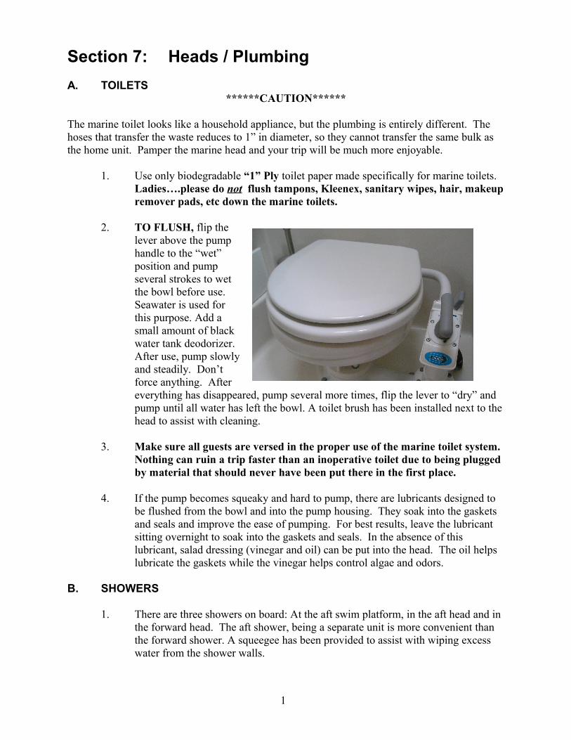
The marine toilet looks like a household appliance, but the plumbing is entirely different. The hoses that transfer the waste reduces to 1” in diameter, so they cannot transfer the same bulk as the home unit. Pamper the marine head and your trip will be much more enjoyable.
1. Use only biodegradable “1” Ply toilet paper made specifically for marine toilets. Ladies….please do not flush tampons, Kleenex, sanitary wipes, hair, makeup remover pads, etc down the marine toilets.
2. TO FLUSH, flip the lever above the pump handle to the “wet” position and pump several strokes to wet the bowl before use. Seawater is used for this purpose. Add a small amount of black water tank deodorizer. After use, pump slowly and steadily. Don’t force anything. After everything has disappeared, pump several more times, flip the lever to “dry” and pump until all water has left the bowl. A toilet brush has been installed next to the head to assist with cleaning.
3. Make sure all guests are versed in the proper use of the marine toilet system. Nothing can ruin a trip faster than an inoperative toilet due to being plugged by material that should never have been put there in the first place.
4. If the pump becomes squeaky and hard to pump, there are lubricants designed to be flushed from the bowl and into the pump housing. They soak into the gaskets and seals and improve the ease of pumping. For best results, leave the lubricant sitting overnight to soak into the gaskets and seals. In the absence of this lubricant, salad dressing (vinegar and oil) can be put into the head. The oil helps lubricate the gaskets while the vinegar helps control algae and odors.
B. SHOWERS
1. There are three showers on board: At the aft swim platform, in the aft head and in the forward head. The aft shower, being a separate unit is more convenient than the forward shower. A squeegee has been provided to assist with wiping excess water from the shower walls.
1

2. The showers discharge into a bilge area where a separate sump pump transfers the water overboard. If you do not notice water being pumped overboard, an inspection of the sump area may be required to determine the cause of the problem; most likely hair preventing operation. Simple cleaning should restore operation.
3. Conservation of hot water is suggested due to the relative small size of the hot water tank. (ie 11 gallons.)
C. THRU-HULLS AND PLUMBING
The toilets draw water for flushing from the thru-hulls on the smaller black hoses in the engine room. If the handles are pointing up (away from the hull) the valves are open and ready for flushing (normally left like this).
There is a floor hatch at the bottom of the stairs to the forward cabins. The seat aft of the aft stateroom bed lifts up. In these two locations are the y-valves which determine where your sewage will go. The valves are black plastic and you will note labels near them which say “overboard”. Please do not pump “overboard” unless it is an emergency. The Y valves have a “zip tie” directing the flow into the holding tanks and preventing overboard discharge. If you point the plastic handle down on the aft Y – valve and up on the forward Y-valve, you will be pointing towards the “overboard” labels. This action directs the sewage overboard. This is illegal to do in all U.S. waters and designated NO discharge area in Canada. The other position, towards the label “holding tank”, directs the sewage into the holding tanks.
E. HOLDING TANKS
1. The holding tanks are located (1) under the floorboard at the forward end of the aft stateroom and (2) under the mid-ship berth. Check the tanks each time you come on board. Tap the tanks; they should sound hollow.
Note:…… the “Tankwatch” light on a panel in each head. These lights will alert you when the holding tank is full. When the “Tankwatch” light comes on the crew should not attempt to use the head “one more time” but use the other head until the full tank can be emptied. This cannot be overemphasized!! Just “One more use….” can turn into an ugly disaster.
2. There are Two Holding tanks: to empty the holding tanks;a. At a marine pump out station….use the deck plates labeled “waste” at the
starboard aft deck, for the aft holding tank; and the starboard mid-ship deck for the forward holding tank. After pumping, following the directions located with the bright orange pump, hose off the deck plates, partially fill the holding tanks with water and empty again to minimize the potential for odors occurring. Finally, flush some deodorant chemical into the tanks to ready for the next use.
b. Use the holding tank Macerator pumps – (only legal in Canadian waters. Never legal in U.S. waters of the Pacific NW) This is an option to using a pump out station. Have a crewmember stand at the waste deck plate starboard, either mid-ship or at the aft quarter and observe for waste flow. From the DC panel, depress the pair of buttons labeled “S” for stern/aft holding tank or “B” for the bow/forward holding tank. Since there are two pumps, each of them has two
1

switches, they will have to operate individually. When the crewmember at the deck plate observes no more flow, release the pump switches to avoid damage to the pumps by running them dry. Once both tanks have been emptied, add a fresh measure of chemicals to the tanks. Borax or Baking Soda may also be added to help control unwanted odors.
Section 8: Cabin Heat
A. SHORE POWER
Turn on the “receptacles” circuit breakers on the A/C switch panel and plug in the portable heater (located in the forward cabin under the bench cushion.) In the winter, normally leave the heater set on “low” to avoid drawing too much current for the 30-amp dock circuit. Running the heater on high could cause the circuit breaker to trip at the electrical panel if you are using the coffee pot and/or microwave at the same time.
B. CRUISE HEAT
This is the 12-volt fan located just below the forward steps in the salon that blows air through a “coolant heat exchanger” heating system attached to the port engine. If the engine is hot, it will blow in hot air. If not, no heat! The switch is located on the port side wall adjacent to the forward cabin steps.
C. WEBASCO DIESEL “HOT WATER” FORCED AIR FURNACE
It is simple to operate provided you pay attention to the details outlined here:1. The 2-way switch for furnace ON or furnace OFF and the thermostat are located on
the port side wall adjacent to the steps to the forward cabin.2. To operate the system turn the thermostat up and the furnace switch “on” (It takes
several minutes for the diesel boiler located below the cockpit to heat up and circulate the water. When it is “hot”, you can hear a dull roar on the port side if you are standing outside.)
3. There are multiple heating units with two speed fan switches located in the forward cabin, mid cabin, galley, and aft cabin. If the fan switches are “ON”, they will blow hot are as soon as the boiler heats the water to the operating temperature. The fan switches will not blow any air until the boiler is hot and “up to temperature.”
To turn the system off, turn the THERMOSTAT down. The boiler must run through a proper “cooling down” cycle which takes several minutes. DO NOT JUST TURN THE BOILER SWITCH OFF.
Section 9: Electrical
A. ”DC” or Direct Current (Batteries)
1. The DC battery selector switches AND THE MAIN BATTERY FUSES are located on the starboard side of the lower helm station.
2. There are eight DC batteries on Island Dreamer. Six (6) “deep cycle” “golf cart” house batteries, and two (2) starting batteries, one for each engine. The starting batteries can be combined in parallel when necessary thru a switch at the lower
1

helm station. The engine batteries are mounted in front of each engine and can be accessed thru the wall hatches in the mid-cabin. Two house batteries are located on the starboard side in front of the starboard engine battery, four house batteries are located below the cockpit hatch in the center and on the STBD side.
3. The DC circuit breakers are all labeled with their respective functions. “DC Master” must be on for any accessories to function (cabin lights, water pressure pump, etc.) AC power is irrelevant to operation of these items.
4. Helm switches must be turned off at the station that they were first turned on from. Duplicate switches are located at the upper and lower helm. Therefore, if you turn on the navigation lights or the anchor light at the upper helm, you must turn them off at the upper helm.
5. The Magnum Inverter/Charger will turn on automatically. If you are on shore power it will charge, if not it will invert (unless the circuit breaker is off.)
6. The main DC House battery switch is just on the Stdb side of the salon under the lower helm engine controls. It is left in the “On” position when the boat is in use.Never turn the battery switch off while the Stbd engine is running!The house batteries are charged by the Stbd engine.
7. There is an “Emergency Battery Crossover Switch” located on the upper left side of the main battery panel. The switch will connect the port and starboard engine batteries. The switch is installed to provide a method to charge a “dead” engine battery in the event of an alternator failure. It should NEVER be used to operate an engine with a failed serpentine belt.
1

8. Check the “fuses” first in the event of any electrical problem.9. The voltmeter is located in the electrical panel on the right side adjacent to the DC
circuit breaker panel and shows the voltage of each battery bank as selected by the switch position: The house battery, which runs all DC systems except the engine, and the engine starting batteries.
10. Voltages can range from 11.0 volts or less (battery low) to 12.6-12.8 volts (battery normal) to 13.2 volts (battery receiving "float" charge) to 13.5 volts or more (receiving "bulk" charge).
11. The entire lighting system including the anchor light on Island Dreamer is equipped with high efficiency “LED” lighting (except the engine room) to minimize the house battery bank drain.
B. “AC” or Alternating Current (Shore Power)
1. The shore power is dual 30 amp with split panel. The shore power cords are stored in the sundeck locker. The adapters are stored in the charter “bag” provided by Crown Yacht Charters. Check the sockets you are about to plug into and determine if they are 30 amp or 20 amp sockets. In most cases it will be necessary to use the splitter, be sure to monitor your amperage to make sure you do not exceed the 30 amp circuit otherwise a trip to the circuit breaker on the dock will be necessary.
2. Ensure the AC master switch is off. Plug the shore power cord into the starboard side mid-ship shore power location. Insert the power cord and twist CW. Tighten the black locking ring. Turn off the circuit breaker at the dock socket. Insert the ships shore power cord to the dock station and restore power with the dock circuit breaker.
3. Check the vessel’s AC panel. The red light indicating “Reverse Polarity” should not be illuminated. DO NOT USE SHORE POWER IF REVERSE POLARITY IS INDICATED. If reverse polarity is indicated and you cannot solve this problem use the onboard APU or DC power. When line 1 and 2 are activated (“Master” on) they should each read ~115 volts.
4. If you only have one dock socket to plug into, use the “splitter” and carefully monitor your usage. If you use more than one appliance at a time (microwave, TV), you may blow a breaker at dock side. If this happens, simply reset, and prioritize your usage. The circuit breakers on the AC panel are self-explanatory. The pairs labeled “Master” must be on before any of those below can work.
5. Once connected to shore power, monitor the AC voltmeter to be sure you have not overloaded the circuit.
Important Note: If the house batteries are low when you first hook up to shore power, and the inverter is turned on (as it should be), the inverter will begin charging its batteries at a very high charging rate, drawing a lot of shore power current. Until this demand reduces (see “The Inverter System” below), you should turn “OFF” other high-current AC appliances such as the water heater.You can then turn on AC appliances as needed. Watch the AC ammeter to be sure you don't exceed the dock's available supply, typically 30 amps.
1

Here are some estimates of AC power consumption for typical appliances:Water Heater - 15 amps Inverter - up to 22 amps Hair Dryer - 12 ampsTV - 1.5 amps Coffee maker - 10 amps Microwave - 10 amps
If no AC power, check the GFIC reset buttons, one located on the galley cabinet outlet, one located on the wall above the main electrical panel.
Section 10: Inverter System
The Inverter system is used to provide AC to the boat when there is no shore power available. It is wonderful, for example, to use the inverter to make a pot of coffee or use the microwave when the engines are running and you are underway, or to watch TV in a quiet anchorage, or use a hair dryer for a few minutes in the morning. But for long-period use of AC by large appliances, the engines must be running or you must have shore power available. That’s because the inverter’s batteries store (conservatively) about 250-300 amp-hours of electricity, that is, they can produce 100 amps for two+ hours, more or less when fully charged.
The microwave, for example, will draw about 100 amps of DC when using the inverter to run it, so in six minutes you use one-tenth of an hour at 100 amps, or ten ampere-hours. That means that in six minutes, you've consumed 10% of the house batteries' stored power. That's okay. But what if you want to microwave a roast for 30 minutes? You used up half your energy on that one job alone! That’s too much use for the inverter that kind of task should only be attempted while the starboard engine is running and you are underway or moored at a dock on shore power. For a short task, the inverter is great: no starting the engines, no noise, no fuss, the power is there. If the engines are running, use it all you wish, as long as you don't try to do two big jobs at once: The inverter can only produce 2,000 watts of energy at a time. The inverter is only wired to the outlets and the microwave. It will not run the hot water heater, battery charger or refrigeration. The house batteries are recharged by a “high output” (160 Amp alternator) and a Balmar “Smart Regulator” running on the starboard engine. Electric boat heaters, particularly, should never be run by the inverter; start the diesel furnace instead!
In addition to making AC out of DC, the inverter can do the reverse! If there is AC available from shore power it will charge batteries! Remember the important note above under “Connecting/Disconnecting Shore Power”: The inverter, if on, will draw a lot of current when bulk charging, so be careful not to overload a shore power circuit.
In summary, the inverter should be on whenever shore power is present, and it may also be left on when underway. It is a good idea to turn the inverter off at anchor, turning it on only when you want to use something briefly, as above; in this way, you will avoid running down the house batteries just because someone left some AC appliance plugged in and forgotten.
Operation of the inverter/charger is automatic. If shore power is connected the device senses AC is available and switches to charger mode. If shore power is not connected and the device senses an AC power demand (from outlets, the vacuum, or the microwave) it switches to inverter mode. It feeds power to the four breakers labeled “Receptacles”, “Microwave”, and “Vacuum Cleaner”.
1

Section 11: Electronics
There are complete manuals aboard for all electronic equipment. Please familiarize yourself with the operation of these devices during fair weather and in familiar waters.
A. VHF Radios
The vessel is equipped with a VHF radio at both helms. The radio at the upper helm is located in the equipment locker to the port side. Use channel 16 for “hailing” only and switch to another channel to conduct a conversation. Make sure at least one other person in your crew is familiar with radio procedure and operation.
B. Color GPS – Chartplotter / Depth Sounder
There are two units that are “net-worked together”, each is labeled. One is located at the flybridge helm, the second at the lower helm. Turn on the power switch on the panels BOTH UNITS MUST BE ON to view all functions. The GPS antenna and charts are read through the flybridge unit, the depth sounder / fish finder are read through the lower helm unit. Way points can be pre-programmed into the GPS unit. There is an operations manual for this unit which you should familiarize yourself with. There is also a way points book on board.
WARNING: DO NOT USE THE GPS AS YOUR SOLE MEANS OF NAVIGATION. ALWAYS REFER TO THE CHARTS ON BOARD FOR THE AREAS WHERE YOU WILL BE NAVIGATING.
C. Radar
The JRC, LCD radar unit is located at the flybridge helm. Again, there is an extensive manual that you should familiarize yourself with prior to using the radar. Note in the manual, the radar must “warm up” after it is turned on for at least 60 - 90 seconds before anything is visible on the display. The radar dome is located on top of the radar arch. The radar does not operate through the Garmin Chartplotters.
WARNING: DO NOT USE THE RADAR AS YOUR SOLE MEANS OF NAVIGATION. ALWAYS REFER TO THE CHARTS ON BOARD FOR THE AREAS WHERE YOU WILL BE NAVIGATING.
D. DEPTH SOUNDERS
There are three (3) depth sounders: one color sounder/fish finder read through the chartplotters; one mounted in the flybridge switch panel; one mounted at the lower helm. IMPORTANT: Depth sounders only tell you how much water is under the hull. Do not rely solely on the depth finder. The accessory switches (upper and lower helm) must be “ON” in order for the depth sounders to operate. There are lots of charts on board, be sure to use them.
The depth sounder/fish finder at the lower station has a forward seeking function, BUT it will only see as far forward as the depth you are presently in (IE, if you are in 25 feet of water, the depth finder can only look 25 feet ahead). Again, be cautious and use the charts.
2

The depth sounders do not operate properly at “high speed.” The signal does not have time to return to the vessel at “high speeds.”
F. SPOTLIGHT
Located at the upper helm only. Controls are to port of helm switches marked “spotlight”. Turn on and use toggle switch to aim. Please do not replace the canvas cover on the spotlight. We have purposely left if off to avoid accidentally starting a fire.
G. STEREO
A CD player and stereo are located above the steps to the aft stateroom. Another stereo is located in the aft berth. Another is located in the forward berth. Another is at the upper helm in the keyed lock to the port side of the wheel. CD’s can only be played in the main salon. The other three units are radio/cassettes. The stereo in the main cabin is equipped with IPOD & USB ports.
Section 12: Trim Tabs
These help trim the bow down over its wave to a planning angle. They can also help to level the boat to either side. Only use at fast speeds, not for maneuvering or docking. Switches are located to the right of both helms. Be careful. Do not trim the bow down too far.
CAUTION: do not press one tab down at the same time you press the other one up, or you could blow a fuse and/or cause a failure of the hydraulic pump. Whenever you slow down off of a plane, run the trim tabs all the way back up. Make sure the trim tabs are all the way up prior to docking. If they are down when docking, they will interfere with prop wash and boat handling.
How do you know if they are up or down?Rock the control either up or down and hold while you count to twelve. Excessive trim tab use can cause erratic hull action. Proceed slowly, a little at a time.
Section 13: Bilge Pumps
The bilge pumps are electric and are hooked to automatic float switches which are connected directly to a battery so that they are always ready to pump. The switches at each helm turn on secondary pumps. After they’ve pumped what they can and begin to draw air, turn these breakers off so you won’t burn the pumps out. Do this at the start of and end of each day. If they seem to be pumping quite a bit longer than usual, notify the Crown Yacht Management staff.
Section 14: Anchoring & Operation of Windlass
1. Anchors: There is a 44 lb Delta “Fast Set” on the bow roller with 200 feet of chain rode and 350 feet of 5/8-inch line rode. NOTE: Chain rode marked in orange at 20 foot intervals, up to 140 ft. The 5/8-inch line is marked every 50-feet with red and yellow paint. There is also a spare or stern anchor if needed. You’ll find the 20 lb anchor and 30 feet of chain and 200 feet of rode in its own “bin” in the aft cockpit.
2

2. Windlass: This is a very powerful winch. YOU CAN LOSE FINGERS OR TOES IN IT! On the upper right corner of the DC panel is the on/off switch for the windlass. Turn the switch on ONLY when you are ready to operate it and turn the switch off as soon as you are finished to prevent accidental injuries. Because the windlass uses a tremendous amount of current, do not operate the windless unless your engines are already running. DO NOT TRY to “haul” the anchor into the roller mount using the windlass. Use the hand crank for the last “foot” or so. The hand crank is located in the bow locker adjacent to the windlass.
3. To Anchor: Have someone standing by at the upper helm ready to maneuver per your instructions.
A. Turn on the windlass switch.B. Remove and untie the anchor lashing. Store in the starboard bow hatch.C. Flip open the caps on the windlass buttons to starboard. Note the arrows
pointing up and down.D. Tap the down arrow a few times and by hand nurse the anchor off the
roller until there is a little weight on the chain. Then lower at will. Recommended scope at least 5:1
E. Always secure the rode to the bow deck cleat, making sure that it isn’t chafing somewhere.
F. Turn off the windlass switch at the breaker panel.G. During the night check that your anchor is holding and that you have room
enough to swing at anchor without getting into shallow water or too near another boat.
4. To Weigh AnchorA. Have someone standing by at the upper helm ready to maintain the boat’s
position once the anchor is free from the bottomB. Flip up the cover on the button with the up arrow. Winch in the rode
keeping watch so that it doesn’t bang into the bow. In rough or windy conditions, have your first-mate at the upper helm SLOWLY and CAREFULLY help drive the boat up to the anchor with engines being careful to not drive over it.
C. Once the anchor is clear of the water, make certain that it doesn’t swing into the bow and ding the gel-coat. When it is up close to the roller, pull the anchor in by hand and set in place. Then take up the slack on the chain by tapping the button (if you haul in the last bit automatically it will slam the anchor in place and damage the gel-coat on the bow. Use the “hand crank” for the last foot or so.
D. Secure the anchor in place.E. Turn off the windlass switch
Section 15: Dinghy and Davit System
The ten foot AB rigid inflatable type dinghy is stowed on a pair of transom davits. A 2.5 HP Mercury outboard is stowed on the motor mount located in the aft cockpit. To lower the dinghy, disconnect the “stand off” brackets and have a crew member assist you as you release the lines and slowly lower the dinghy using the block and tackle. One person can handle this task, as long as you go slowly. Please lower the dinghy carefully into the water, rather than letting it slam
2
down. Loosen the outboard from the cockpit mount and carefully place the outboard on the transom of the dinghy. Tighten the motor mounts and attach the safety line so the motor is secured to the dinghy transom. Next remove the hoist line from the dinghy (be sure you have the painter (a line from the bow of the dinghy) attached to the boat. Secure the hoist rope inside the cockpit, and you’re underway!
If you notice that the dinghy needs inflation, the pump is located in the locker on the sun deck. The pressure in the inflatable “tubes” fluctuates with the air temperature and should be “firm” but not “hard as a rock”.
To bring in the dinghy, reverse the above procedure. If are using the outboard:Don’t “Ram” the beach; you can bump up to the beach gently and step ashore over the bow, pulling the dinghy a little more ashore as each person off-loads. Please don’t drag the dinghy on the rocks because that will destroy the bottom. Don’t forget to raise the outboard when the boat is beached!
Dinghy Outboard Operation: Check fuel supply in outboard tank (50:1 mixture.) A full tank lasts 2-3 hours. Open fuel tank vent (knob on fuel cap) Open fuel shut-off valve “vertical” (located on the lower left side of the engine cover.) If engine is cold, close choke lever, move throttle lever to start, and pull start cord. If engine is hot, it will start without the choke. DO NOT OPERATE THE OUTBOARD IN SHALLOW OR ROCKY AREAS. To stow, close fuel shut off valve “horizontal”, close fuel tank vent and replace dinghy
outboard on cockpit motor mount. PLEASE to not tow the dinghy and PLEASE rinse it out after every use.
For safety, and compliance with U.S. rules, there should be a life jacket aboard the dinghy for each passenger aboard whenever the dinghy is at sea.
Keeping the dinghy clean, and carefully stowing its contents will make your trip a safer and more pleasant one! After you have finished using the dinghy, remove outboard safety cable and lift the outboard and replace it on the motor mount in the aft cockpit. Tighten the mounting clamps and secure the outboard in place.
Be sure to use 50:1 pre mix gas in the outboard fuel tank. There is a zip lock bag of spares for the dinghy outboard in the “SPARES” container in the aft cockpit storage locker that includes a spark plug, a spare prop, shear pins, a cotter pin, and a throttle/choke nob.
Please check to make sure all dinghy lines are “on board” and are secure in the cockpit, the dinghy outboard is secured on the cockpit motor mount, and dinghy life jackets are stowed before any engines are started.
Section 16: Miscellaneous
A. Berths1. To use the salon berth, lift the dinette table from its wall socket, remove the table
leg, lift the aft dinette cushion and place the table on the wood edge before replacing the aft cushion. The middle cushion is stowed in the mid-ship berth.
2

2. The mid-ship berth has excess storage under the ‘headboard’ which is hinged at the top and lifts up and away from the berth, providing ample space for duffel bags and extra gear.
3. The forward stateroom has three deep lockers located under the mattress in addition to the hanging locker.
B. Vacuum System1. The central vacuum system and attachments are located under the forward salon
settee cushion. The hose is stored under the aft dinette cushion. This unit is AC only therefore shore power or the inverter must be operational and the circuit breaker in the electrical panel must be activated to use the vacuum. To use the vacuum, lift up the hinged “flap” on the black box and plug the hose into the opening.
C. Canvas1. The front window cover is usually stowed in the sundeck locker.2. The bridge console, settee and helm seat covers are stowed in the port side fly
bridge locker.
D. BBQ Grill1. LOWER Dinghy so grill does not burn dinghy.2. Install regulator and propane bottle from storage container. DO NOT MOTOR
WITH PROPANE TANK INSTALLED ON GRILL.3. Clean grill after each use.4. Replace regulator, tank, and cleaning brush in storage container.5. Replace canvas grill cover after grill has cooled.6. LOWER Dinghy so grill does not burn dinghy.
2

E. TV & DVD Player1. The LED TV and DVD player are located in the recessed compartment directly
above the stairway entry to the lower aft cabin along with the AM-FM CD player.2. The LED TV and the DVD player must be plugged into the 110 volt outlet on the
wall below the devices.3. The remotes and the cords for these devices are stored in the recessed area above
the DVD player.4. The inverter must be “on” (if you are not plugged in to shore power) to operate
these devices however they use a very small amount of power.
2

F. Spare Parts & Tools1. Spare parts are located under the aft cushion of the dinette2. Batteries and smaller items are also located there.3. Larger spares are located in the bin in the cockpit locker.4. Motor oil and coolant are located in the engine bilge area.5. Tool box is under the aft cushion of the dinette.
Section 17: Securing
A. Once securely moored at the dock, connect the shore power to the AC supply.
B. The Inverter / Charger should turn on automatically.
C. On the DC panel: Turn off the “water pump”
D. On the AC panel: Turn off the water heater. (Do not leave the water heater on if there is not water in the tank.) Leave the battery charger and AC receptacles on.
E. Check the inventory (especially fenders and tie off the fender holders so they won’t slip below the dock.)
F. When leaving the boat, close the windows and lower the blinds. Lock the boat.
G. Perform a last inspection as you leave the boat, checking for personal gear, locked windows and loose gear onboard. Check the tie-up and fenders once again.
Have fun and thanks for choosing Island Dreamer!
2

Section 18: “What to Do If”(& Miscellaneous Reminders)
ANCHOR CHAIN WON’T COME OUT OF CHAIN LOCKERThe chain is continuous, secured at both ends, and cannot tangle. But sometimes a pile of chain will fall over, and one loop of chain will fall through another loop. Usually you can clear this by grasping the chain where it exits the hawse pipe from the chain locker with your hands, and pulling it up or down to “jiggle” the loop out of the chain; you may have to retrieve some chain to do this, in order to have enough slack to jiggle it! It is rare when this will not clear the jam. The other solution: go below and clear the tangle in the chain locker. Caution: Turn off the windlass breaker, wear gloves when manhandling chain!
ANCHOR FOULED, CAN’T RAISE ITThis can happen if you “pull the boat to the anchor” with the windlass. You should move the boat under power until it is over the anchor, or, even better, slightly ahead of it before hauling. Usually this will clear it. Otherwise, take a line and form a fixed, loose loop around the chain. Weight the loop, and lower it down the line until it reaches the bottom, sliding down the chain. Then, using the dinghy, take the line forward past the anchor so that you can pull the anchor out, opposite the direction its flukes are pointing.
ANCHOR WINDLASS WON’T TURNIf the motor is running, is the clutch tight? Use the windlass handle in the deck locker just aft and to starboard of the anchor windlass.
BATTERIES (HOUSE) KEEP RUNNING DOWNHave you run the Stbd engine enough? The house batteries are charged primarily by the Stbd engine when underway. Is something left on (like the engine room lights, too many electronics, etc.) that is too great a load for the time not charging?
ENGINE OVERHEATSIs the drive belt for the water pump intact? Spare belts are in the engine room spares kit. Is the sea strainer clogged? See that section in this manual. Is the impeller shot? If sea strainer is clear and belt is good, this is likely. Change (spare in spares kit) or call a mechanic. Do not run engine if it overheats!
ENGINE WON’T STARTCheck battery, battery switches. If starter turns, assume fuel problem: check fuel tanks, if necessary re-prime engine or call a mechanic (see Cummins engine manual).
EXHAUST STEAMS Visible exhaust steam at higher speeds can occur, although there should never be any significant smoke after the engine warms up. The steam is a function of the humidity; check temp gauges.
FLASHLIGHTSFlashlights are on the counter in the salon adjacent to the lower helm.
2

FOG DELAYS RETURNCall Crown Yacht Management by telephone or VHF marine operator and advise for instructions.
HEAD WON’T FLUSHHave you over-filled the holding tank? Pump it to allow more effluent to enter it. See the “Head” section of this manual.
HIT A FISH NETEngine in Neutral: don’t try to back off, you may foul the net more. Try pulling the boat back with the dinghy & outboard. Get assistance from the fisherman. You are responsible for damage to a net!
HIT A LOG OR ROCKSee EMERGENCY PROCEDURES, next section.
HOUSE BATTERY SEEMS COMPLETELY DEADDid you turn the battery switch off, or switch off the “DC MAIN” breaker? Turn the batteries back on! Check the fuses behind the doors of the main battery switches.
NO FRESH WATER? If fresh water pump won't run: Is “Fresh Water Pump” breaker on? Water in tank?
NO AC SHORE POWER? Is cable in connector? Switch in "shore power" position? Is breaker on panel "on"? Check GFCI reset buttons on the two outlets (galley outlet & outlet by main electrical)
OUTBOARD WON'T RUNIs tank vent open? Is fuel line on? Is gas in the tank? Did you choke it for first pulls?
PROPANE GRILLThe propane regulator, tank, and cleaning brush checked out from Crown Yacht Management and can be stowed in the sun deck locker or cockpit storage hatch. Mount the grill securely in the transom mount. Screw on a propane bottle, turn on, and light. Let the grill cool before re-storing it!
PROPELLER FOULED OR DAMAGEDBest thing: have the prop checked by a diver or dive it yourself if able. Check for vibration. Try turning shaft by hand in engine room, both should be turn-able with engine in neutral. Is shaft noisy, or does it load engine? Call for assistance. See emergency procedures, next chapter.
SPARESIn the cockpit locker: Spares, belts hose clamps, gasket materials, oil, oil filters, WD-40, duct tape, etc.
TOOLS, METERSThere is a full set of tools aboard.
2
Section 19: Emergency Procedures
Protect your lives first!Put on life jacketsContact the Coast Guard with an emergency "MAYDAY" call.If adrift, prepare to anchor to keep the boat from drifting into danger.If the boat is really sinking, consider "beaching it" if necessary.Launch the dinghy and prepare to board if necessary. Take a cell phone or handheld VHF radio, if available. Be sure to wear life jackets!
Then, worry about the boat!In a true emergency, you certainly are authorized to call for immediate commercial assistance as minimally required to assure the safety of you and the boat. It is not an emergency, however, if neither you nor the boat are at risk. For all non-emergency assistance or mechanical repairs done by others, the charter company MUST give prior approval for you to be reimbursed!
If you think it may not be an emergency:If you have any concern about your long-term safety, contact the Coast Guard, either normally or using an urgent "PAN" call. Tell them that you are calling to advise them about your situation, so they can keep in touch.
Be sure that the status and safety of the boat and crew is someone's responsibility while you sort out the boat's problem. For example, delegate your mate to keep a watch for hazards, or to operate the boat on course slowly while you deal with the difficulty.
Here is a checklist for solving the problem:(A) Isolate it; (B) Get the manuals; (C) Get parts;(D) If necessary, call the charter company for help.
Over the years, most problems with charter boats are caused by misuse! Holding tanks overflow because they aren't checked; heads clog because foreign matter (especially facial tissues and tampons) are put in them; engines fail because they run out of fuel, then must be "purged" to re-start. Use the boat carefully, and you'll avoid these problems. Almost all problems that are not operator-caused, i.e., that are boat deficiencies, are caus-ed by pumps that fail, hoses and belts that break, and seawater strainers that get clogged. Generally, these problems are annoyances, and usually they are inconvenient, but they still can happen. Try to stay calm, collected, and be a professional by dealing with the problem in a businesslike, calm way. It will make everyone's day a better one!
Hitting a Log, Rock, or Debris ----- Please Don’t!Hitting a log is a real risk in our Northern waters because logging, and "log rafts," are such a big part of our commerce.
2

If you hit a log: Did you put a hole in the boat? Idle the engine, then think: usually, you can tell
just by where the noise of the hit came from. Check the bilges (don't forget the lazarette area, where the rudder posts are) after putting the engine into idle and/or neutral, if necessary.
If you did "hole" the boat, go immediately to the "If an Emergency" on the preceding pages.
If no hole, and still idling, is the boat vibrating?
If "yes", run on one engine only or call for assistance. Call the charter company after you reach the closest safe harbor.
If there is no vibration on the engine, you probably did no running gear damage. Congratulations! Our diver will check your vessel’s bottom upon your return, just as after every charter.
3