iso/iec wdtr 18037 wg14 n948 iso/iec wdtr … for c, definable in a range of precision and...
TRANSCRIPT

ISO/IEC WDTR 18037
- 1 -
WG14 N948
ISO/IEC WDTR 18037.1
Programming languages , their env ironments and s ystem software interfaces —Extensions for the programming language C to suppo rt embedded p rocessors
Version for SC22 Registration Ballot
Contents
1 GENERAL ................................................................................................................5
1.1 Scope................................................................................................................................................... 5
1.2 References .......................................................................................................................................... 5
2 FIXED POINT ARITHMETIC....................................................................................5
2.1 Overview and principles of the fixed point datatype............................................................................ 52.1.1 The datatypes............................................................................................................................ 52.1.2 Overflow and Rounding............................................................................................................. 72.1.3 Type conversion, usual arithmetic conversions ........................................................................ 82.1.4 Operations involving fixed point types....................................................................................... 92.1.5 Type-generic functions ............................................................................................................ 112.1.6 Fixed point constants............................................................................................................... 122.1.7 List of open issues................................................................................................................... 12
2.2 Detailed changes to ISO/IEC 9899:1999 .......................................................................................... 12
3 BASIC I/O HARDWARE ADDRESSING < IOHW.H HEADER>.............................13
3.1 Overview and principles .................................................................................................................... 133.1.1 The abstract model.................................................................................................................. 143.1.2 I/O register characteristics....................................................................................................... 153.1.3 The most basic I/O operations ................................................................................................ 153.1.4 The access_spec_macros....................................................................................................... 16
3.2 The IOHW interface........................................................................................................................... 173.2.1 Function like macros for single register access ...................................................................... 173.2.2 Function like macros for register buffer access....................................................................... 17
ISO/IEC WDTR 18037
- 2 -
3.2.3 Function like macros for access_spec initialisation................................................................. 183.2.4 Function for access_spec copying .......................................................................................... 19
4 MULTIPLE ADDRESS SPACES SUPPORT ......................................................... 20
4.1 Overview and principles .................................................................................................................... 204.1.1 Named address space support. .............................................................................................. 204.1.2 Processor-architecture-based multiple address space support .............................................. 204.1.3 Application-defined multiple address space support............................................................... 20
4.2 Impact on the C language usage. ..................................................................................................... 214.2.1 Variable declaration................................................................................................................. 214.2.2 Pointer declaration................................................................................................................... 214.1.4 Pointer usage .......................................................................................................................... 214.1.5 Portability between implementations....................................................................................... 21
ANNEX A....................................................................................................................... 22
A.1Fixed point ......................................................................................................................................... 22A.1.1 The fixed point datatypes ........................................................................................................ 22A.1.2 Overflow and Rounding........................................................................................................... 25A.1.3 Type conversions, usual arithmetic conversions..................................................................... 25A.1.4 Operations involving fixed point types..................................................................................... 26A.1.5 Type-generic functions ............................................................................................................ 27A.1.6 Fixed point constants .............................................................................................................. 27
ANNEX B....................................................................................................................... 28
B.1General .............................................................................................................................................. 28B.1.1 Recommended steps .............................................................................................................. 28B.1.2 Compiler considerations.......................................................................................................... 28
B.2Overview of I/O hardware connection options................................................................................... 29B.2.1 Multi-addressing and I/O register endian ................................................................................ 29B.2.2 Address Interleave................................................................................................................... 30B.2.3 I/O connection overview: ......................................................................................................... 30B.2.4 Generic buffer index ................................................................................................................ 31
B.3Access_specs for different I/O addressing methods......................................................................... 31
B.4Atomic operation................................................................................................................................ 33
B.5Read-modify-write operations in multi-addressing cases.................................................................. 33
B.6I/O initialisation .................................................................................................................................. 33
ANNEX C....................................................................................................................... 35
C.1Generic access_spec descriptor ....................................................................................................... 35

ISO/IEC WDTR 18037
- 3 -
C.1.1 Background ............................................................................................................................. 35
C.2Syntax specification........................................................................................................................... 35
C.3Examples of access_spec descriptors .............................................................................................. 37
C.4Parsing............................................................................................................................................... 39
C.5Comments on syntax notation ........................................................................................................... 40
ANNEX D .......................................................................................................................41
D.1Migration path for iohw.h implementations........................................................................................ 41
D.2iohw.h implementation example based on C macros........................................................................ 41D.2.1 The iohw.h header................................................................................................................... 41D.2.2 The users I/O register definitions ............................................................................................ 43D.2.3 The driver function................................................................................................................... 44
ANNEX E........................................................................................................................46
E.1Embedded systems extended memory support ................................................................................ 46E.1.1 Modifiers for named address spaces ...................................................................................... 46E.1.2 User-defined device drivers..................................................................................................... 47
ANNEX F........................................................................................................................50
F.1 Circular buffers .................................................................................................................................. 50
F.2 Complex data types........................................................................................................................... 51

ISO/IEC WDTR 18037
- 4 -
INTRODUCTION
In the fast growing market of embedded systems there is an increasing need to write applicationprograms in a high-level language such as C. Basically there are two reasons for this trend:programs for embedded systems get more complex (and hence are difficult to maintain in assemblylanguage) and the different types of embedded systems processors have a decreasing lifespan(which implies more frequent re-adapting of the applications to the new instruction set). The codere-usability achieved by C-level programming is considered to be a major step forward in addressingthese issues.
Various technical areas have been identified where functionality offered by processors (such asDSPs) that are used in embedded systems cannot easily be exploited by applications written in C.Examples are fixed-point operations, usage of different memory spaces, low level I/O operationsand others. The current proposal addresses only a few of these technical areas.
Embedded processors are often used to analyse analogue signals and process these signals byapplying filtering algorithms to the data received. Typical applications can be found in all wirelessdevices. The common datatype used in filtering algorithms is the fixed point datatype, and in orderto achieve the necessary speed, the embedded processors are often equipped with specialhardware support that datatype. The C language (as defined in ISO/IEC 9899:1999) does notprovide support the fixed point arithmetic operations, currently leaving programmers with no optionbut to hand-craft most of their algorithms in assembler. This Technical Report specifies a fixed pointdatatype for C, definable in a range of precision and saturation options. In this manner, fixed pointdata is supported as easily as integer and floating point data throughout the compiler, including thecritical optimisers leading to highly efficient code.
Typical for the mentioned filtering algorithms is the usage of polynomials whereby data from onesource (inputvalues) is multiplied by coefficients coming from another source (memory). Ensuringthe simultaneous flow of data and coefficient data to the multiplier/accumulator of processorsdesigned for FIR filtering, for example, is critical to their operation. In order to allow the programmerto declare the memory space from which a specific data object must be fetched. This TechnicalReport specifies basic support for multiple address spaces. As a result, optimising compilers canutilise the ability of processors that support multiple address spaces, for instance, to read data fromtwo separate memories in a single cycle to maximise execution speed.
[Editor's note: Are all above paragraphs necessa ry?]
As the C language has matured over the years, various extensions for accessing basic I/Ohardware (iohw) registers have been added to address deficiencies in the language. Today almostall C compilers for free-standing environments and embedded systems support some method ofdirect access to iohw registers from the C source level. However, these extensions have not beenconsistent across dialects.This Technical Report provides an approach to codifying common practice and providing a singleuniform syntax for basic iohw register addressing.

ISO/IEC WDTR 18037
- 5 -
Information techno logy — Programming langu ages, theirenvironments and system software interfaces — Extensions forthe programming langu age C to suppo rt embedded processors
1 General
1.1 Scope
This Technical Report specifies a series of extensions of the programming language C, specified bythe international standard ISO/IEC 9899:1999.
Each clause in this Technical Report deals with a specific topic. The first subclause of each clausecontains a technical description of the features of the topic. It provides an overview but does notcontain all the fine details. The second subclause of each clause contains the editorial changes tothe standard, necessary to fully specify the topic in the standard, and thereby provides a completedefinition. If necessary, additional explanation and/or rationale is given in an Annex.
1.2 ReferencesThe following standards contain provisions which, through reference in this text, constituteprovisions of Technical Report. For dated references, subsequent amendments to, or revisions of,any of these publications do not apply. However, parties to agreements based on this TechnicalReport are encouraged to investigate the possibility of applying the most recent editions of thenormative documents indicated below. For undated references, the latest edition of the normativedocument referred applies. Members of IEC and ISO maintain registers of current validInternational Standards.
ISO/IEC 9899:1999, Information technology – Programming languages, their environments andsystem software interfaces – Programming Language C.
2 Fixed po int arithmetic
[EDITORS Note: need to check which po rtions o f 2.1 shou ld go into 2.2 or A.2.1]
2.1 Overview and p rinciples of the fixed po int datatype
2.1.1 The datatypesFixed point datavalues are either integer datavalues, fractional datavalues (with value between -1.0and +1.0), or datavalues with an integral part and a fractional part. As the position of the radix pointis known implicitly, operations on the values of these datatypes can be implemented with (almost)

ISO/IEC WDTR 18037
- 6 -
the same efficiency as operations on integral values. Typical usage of fixed point datavalues andoperations can be found in applications that convert analogue values to digital representations andsubsequently apply some filtering algorithm. For more information of fixed point datatypes, seeclause A.1 in the Annex of this Technical Report.
For the purpose of this Technical Report, two new datatypes are added to the C language: thefract datatype and the accum datatype. The fract datatype has no integral part, hencevalues of the fract datatype are between -1.0 and +1.0. The value of an accum datavaluedepends on the number of integral bits in the datatype. Note that the fract datatype correspondswith the type-A datatype, as described in the Annex, while the accum datatype corresponds to thetype-B datatype, mentioned in the Annex.
The fixed point datatypes are designated with the corresponding new keywords and type-specifiersfract and accum. These type-specifiers can be used in combination with the existing type-specifiers short, long, signed and unsigned to designate the allowed fixed point types,yielding
short fract short accumfract accumlong fract long accum
and their signed and unsigned variations.
The following interpretations and/or restrictions apply:[Editors no te: do all restrictions app ly? Specifi cally: required suppo rt for uns ignedfixed po int, and required the nu mber of different fi xed po int types ]1. If neither of the signed or unsigned keywords is used, a signed fixed point datatype is
implied.2. It is implementation defined whether unsigned fixed point datatypes are supported.3. If unsigned fixed point datatypes are supported, an unsigned fixed point datatype has one bit
more precision (one additional fractional bit) than its corresponding signed fixed point datatype.4. The number of integral bits and fractional bits in a fixed point datatype is implementation
defined. However, the minimum number of bits in each for each fract type (signed orunsigned) is as follows:
short fract: 8 bitsfract 16 bitslong fract 32 bits
Each accum type has exactly the same number of fractional bits as its corresponding fracttype, plus a minimum of 4 integral bits. [Editors no te: it is proposed to change thissentence to: Each accum type has at least the same number of fractional bits as itscorresponding fract type, plus a minimum of 4 integral bits. See discuss ion in A.1.1] Thenumber of integral bits in the accum types must not decrease in the sequence short accum,accum, long accum.
5. A conforming implementation shall support at least two different signed fract fixed pointdatatypes, and one signed accum fixed point datatype.

ISO/IEC WDTR 18037
- 7 -
6. The concept container is used to identify the address and the size (expressed in bytes) of a fixedpoint datavalue. A container is composed of a contiguous sequence of one or more bytes,holding a fixed point datavalue. Some requirements:- the size of the container in bits is a multiple of the number of bits per byte for the machine,
and the address of the container is a regular byte address;- the number of databits (fractional bits and integral bits) in a fixed point datavalue is not
greater than the number of bits in its container;- the (machine) address of a fixed point datavalue is the (machine) address of (exactly) one of
the bytes that form the container;- if the size of the container in bits is greater than the number of bits needed for the fixed point
datavalue, the remaining bits (called paddingbits) cannot be used for other purposes;- if there are paddingbits involved, it is still required that the (machine) address of (one of the
bytes of) the container fully identifies the (machine) address of the fixed point datavalue; inother words: the alignment of the fixed point datavalue within the container is implicitlyknown (from its fixed point datatype designation);
- at programming level (i.e., in the programming language) all fixed point datatypes with thesame valuespace (the same number of databits, same signedness, same position of theradix point) are the same; there is no distinction between these datatypes with respect todifferent alignment/padding strategies.
2.1.2 Overflow and Round ing
Conversion of a real arithmetic value to a fixed-point type may overflow and/or may requirerounding. When the source value does not fit within the range of the fixed point type, the conversionoverflows. Two different behaviors are defined for overflow:
- Saturation: The source value is replaced by the closest available fixed point value. (Forunsigned fixed point types, this will be either zero or the maximal positive value of the fixed pointtype. For signed fixed point types it will be the maximal negative or maximal positive value ofthe fixed-point type.)
- Modular wrap-around: For unsigned fixed point types, the source value is replaced by a valuewithin the range of the fixed-point type that is congruent (in the mathematical sense) to thesource value modulo 2^N, where N is the number of integral bits in the fixed point type. (Forexample, for unsigned fract types, N equals 0, and the source value is replaced by a valuebetween 0 and 1 that is congruent to the source value modulo 1.) For signed fixed point types,the source value is replaced by a value within the fixed point range that is congruent to thesource value modulo 2^(N+1), where N again is the number of integral bits in the fixed pointtype. (In either case, the effect is to discard all bits above the most significant bit of the fixed-point format.)
Overflow behavior is controlled in two ways:
- Either of the type qualifiers sat and modwrap (but not both) can be added to a fixed point typeto control overflow behavior (e.g., sat fract and modwrap long accum).

ISO/IEC WDTR 18037
- 8 -
- In the absence of an explicit sat or modwrap qualifier, overflow behavior is controlled by theFX_OVERFLOW pragma. The FX_OVERFLOW pragma follows the same scoping rules asexisting STDC pragmas (see clause 6.10.6 of the C standard), and has the following syntax:
#pragma STDC FX_OVERFLOW overflow-switchwhere overflow-switch is one of SAT, MODWRAP, or DEFAULT. When the state of theFX_OVERFLOW pragma is DEFAULT, fixed point overflow has undefined behavior. The defaultstate of the FX_OVERFLOW pragma is DEFAULT.
If (after any overflow handling) the source value cannot be represented exactly by the fixed pointtype, the source value is rounded to either the closest fixed point value greater than the sourcevalue (rounded up) or to the closest fixed-point value less than the source value (rounded down).Whether rounding is up or down is implementation-defined and may differ for different values anddifferent situations.[Editors no te: shou ld this be con trollable via a pragma?]
2.1.3 Type conversion, usual arithmetic conversions
All conversions between a fixed point type and another arithmetic type (which can be another fixedpoint type) are defined. Overflow and rounding are handled according to the usual rules for thedestination type. Conversions from a fixed point to an integer type round toward zero. Therounding of conversions from a fixed point type to a floating-point type is unspecified.
For determining the usual arithmetic conversions, each fixed point datatype has a fixed pointconversion rank. The following types are listed in order of increasing rank:
short fract, fract, long fract, short accum, accum, long accum.Each unsigned fixed point datatype has the same rank as its corresponding signed fixed pointdatatype.
Discussion: the above specified conversion rank favors value over precision, and has as strongpoint its simplicity. An alternative scheme, whereby both the value and the precision are taken intoaccount is the following lattice (the '>' symbol indicates increasing rank):
short fract > fract > long fractshort accum > accum > long accumshort fract > short accumfract > accumlong fract > long accum
If, with this scheme, the usual arithmetic conversion rule is applied on two fixed point types, theresulting type is the type with a rank as least as high as the rank of each of the two types accordingto the above rules. The resulting type may be different from both the operand types: the resultingtype for a long fract and short accum type is long accum.
In addition to the standard usual arithmetic conversions (see 6.3.1.8), after the conversion rule forconversion to float, and before the integer promotion rules, the following rules should be inserted:
Otherwise, if one operand has fixed point type and the other operand has integer type, thenno conversions are needed.

ISO/IEC WDTR 18037
- 9 -
Otherwise, if both operands have signed fixed point types, or if both operands haveunsigned fixed point types, then the operand with the lesser fixed point conversion rank isconverted to the type of the operand with the greater rank.
Otherwise, if one operand has signed fixed point type and the other operand has unsignedfixed point type, the both operands are converted to the signed type corresponding to theoperand type with greatest fixed point conversion rank.
If the type of either of the operands has the sat qualifier, the resulting type shall have thesat qualifier; if the type of either of the operands has the modwrap qualifier, the resultingtype shall have the modwrap qualifier. [Note: for precision of specification sake, this lastrequirement might have to be merged into the previous two]
It is recommended that a conforming compilation system provide an option to produce a diagnosticmessage whenever the usual arithmetic conversions cause a fixed point operand to be converted tofloating point.
2.1.4 Operations involving fixed po int types
2.1.4.1 Unary operators
2.1.4.1.1 Prefix and p ostfix increment and d ecrement operators
The prefix and postfix ++ and -- operators have their usual meaning of adding or subtracting theinteger value 1 to or from the operand and returning the value before or after the addition orsubtraction as the result.
2.1.4.1.2 Address and ind irection o perators
[Editors no te: new text] If the type of the operand of the unary & has a fixed point type, theaddress of the (smallest) container holding the fixed point value is returned.
It is a constraint violation to apply the unary * operator (the indirect operator) to an operand havingfixed point datatype. [Editors no te: is this needed? Clause 6.5.3.2 already has : Theoperand o f the una ry * operator shall have po inter type]
2.1.4.1.3 Unary arithmetic operators
The unary arithmetic operators plus (+) and negation (-) are defined for fixed point operands, withthe result type being the same as that of the operand. The negation operation is equivalent tosubtracting the operand from the integer value zero.
2.1.4.1.4 The sizeof operator
New text: When applied to an operand that has fixed point type, the sizeof operator returns thesize in bytes of the smallest container holding the operand.

ISO/IEC WDTR 18037
- 10 -
2.1.4.2 Binary operators
2.1.4.2.1 Binary arithmetic operators
The binary arithmetic operators +, -, *, and / are supported for fixed point datatypes, with theirusual arithmetic meaning, as follows:
- If the type of one operand is a fixed point type, and the type of the other operand is an integertype, the result type is the type of the fixed point operand. The integer operand is not firstconverted to fixed point before the operation is performed.
- Otherwise, the usual arithmetic conversions apply, and the type of the result is the common typeto which both operands are converted. If both operands are fixed point, the result type includesany sat or modwrap qualifier from either operand. (For example, if the operands of anaddition have types long accum and sat fract, the result type is sat long accum.)It is a constraint error if one fixed point operand to have a sat qualifier and the other amodwrap qualifier.
If the result type of an arithmetic operation is a fixed point type, the operation is performed exact(according to its mathematical definition), and then overflow handling and rounding is performed forthe result type as explained in the earlier section on Overflow and Rounding. However, if themathematical result of the * operator is exactly 1, the closest smaller value representable by thefixed point result type may be returned as the result, even if the result type can represent thevalue 1 exactly. Correspondingly, if the mathematical result of the * operator is exactly -1, theclosest larger value representable by the fixed point result type may be returned as the result, evenif the result type can represent the value -1 exactly. The circumstances in which a 1 or -1 resultmight be replaced in this manner are implementation-defined.
2.1.4.2.2 Bitwise shift operators
Shifts of fixed point values using the standard << and >> operators (including the resulting overflowand rounding behavior) are defined to be equivalent to multiplication or division by a power of two.The right operand is converted to type int and must be nonnegative and less than the total numberof (nonpadding) bits of the fixed point operand (the left operand). The result type is the same asthat of the fixed point operand. An exact result is calculated and then converted to the result type inthe same way as the other fixed point arithmetic operators.
2.1.4.2.3 Relational operators, equali ty operators
The standard relational operators (<, <=, >=, and >) and equality operators (==, and !=) acceptfixed point operands. The usual arithmetic conversions are applied before the comparison is made.Fixed point and integer values are compared directly; the integer operand is not converted to fixedpoint before the comparison is made.
2.1.4.3 Ass ignment operators
The standard assignment operators +=, -=, *=, and /= are defined in the usual way when eitheroperand is fixed point. Note, in particular, that, given the declarations

ISO/IEC WDTR 18037
- 11 -
sat fract a; modwrap fract b;
the expression "a += b" violates a constraint because "a + b" does.
The standard assignment operators <<= and >>= are defined in the usual way when the leftoperand is fixed point.
2.1.5 Type-generic functions
In this clause, a number of type-generic functions working on fixed point values are defined. Notethat (most of) the functions defined here are truly type-generic functions, and therefore take theapproach for type-generic functions, as defined in clause 7.22 from the C standard, one step further.For a discussion, see the rationale in A.1.5.
Editors Note: What is the relation with the text in 7.22 of the C standard? Is the list oftype-generic func tions spec ifi ed there also app licable to fixed po int types? The remight be so me func tions o f interest: fma, frexp.
2.1.5.1 The roundfx function
The roundfx function rounds the value of a fixed point argument to a specified number offractional bits. The function takes two arguments:
roundfx ( <fixed-value> , <num-fract-bits> )
The roundfx function is type-generic on the first argument: the result type is the type of the firstargument, which must be fixed point. The value of the second argument is (converted to?) typeint and must be nonnegative and less than the number of fractional bits in the fixed point type.The fixed point value is rounded to the specified number of fractional bits, and this rounded value isreturned as the result. The rounding applied is to-nearest, with unspecified rounding direction in thehalfway case. Fractional bits beyond the rounding point are set to zero in the result.
2.1.5.2 The countls function
The countls function is a type-generic function with a single fixed point argument. The result typeof the function is int; the return value is defined as follows:- if the value of the fixed point argument a is non-zero, the return value is the largest integer k for
which the expression a<<k does not overflow;- if the value of the fixed point argument is zero, an integer value is returned that is at least as
large as N-1, where N is the total number of (nonpadding) bits of the fixed point type of theargument.
2.1.5.3 The bits function

ISO/IEC WDTR 18037
- 12 -
*** MORE WORK NEEDED IN THIS SECTION.
The bits function is a type-generic function with a single fixed point argument. The bitsfunction returns an integer value equal to the fixed point value of the argument multiplied by 2^F,where F is the number of fractional bits in the fixed point type. The result type is a signed integertype big enough to hold all valid result values for the given fixed point argument type. For example,if fract is 16 bits, then after the declaration
fract a = 0.5;
the value of bits(a) is 0.5 * 2^15 = 0x4000.
2.1.5.4 The fpabs function
The fpabs function is a type-generic function with a single fixed point operand. The result type isthe same as the type of the argument, and the return value is the absolute value of the operand.Overflow is possible and is handled as specified in the section on Overflow and Rounding .
2.1.6 Fixed po int constants
See discussion text in Annex.
2.1.7 List of open issues
- contents of the <stdfix.h> header file- fixed point types and default argument promotions- conversion specifiers for scanf and printf format strings.
2.2 Detailed changes to ISO/IEC 9899:1999
ISO/IEC WDTR 18037
- 13 -
3 Basic I/O hardware address ing
3.1 RationaleIdeally it should be possible to compile C or C++ source code which operates directly on iohwregisters with different compiler implementations for different platforms and get the same logicalbehaviour at runtime. As a simple portability goal the driver source code for a given I/O hardwareshould be portable to all processor architectures where the hardware itself can be connected.
3.1.1 Basic Standardisation Objectives
A standardisation method for basic I/O hardware addressing must be able to fulfil threerequirements at the same time:
• A standardised interface must not prevent compilers from producing machine code that has noadditional overhead compared to code produced by existing proprietary solutions. Thisrequirement is essential in order to get widespread acceptance from the market place.
• The I/O driver source code modules should be completely portable to any processor systemwithout any modifications to the driver source code being required [i.e. the syntax shouldpromote I/O driver source code portability across different execution environments.]
• A standardised interface should provide an “encapsulation” of the underlying accessmechanisms to allow different access methods, different processor architectures, and differentbus systems to be used with the same I/O driver source code [i.e. the standardisation methodshould separate the characteristics of the I/O register itself form the characteristics of theunderlying execution environment (processor architecture, bus system, addresses, alignment,endian, etc.].
3.2 Basic I/O-Hardware address ing h eader <iohw.h>
The purpose of the I/O hardware (iohw) access functions defined in a new header file <iohw.h> is topromote portability of iohw driver source code across different execution environments.
3.2.1 Overview and p rinciplesThe iohw access functions create a simple and platform independent interface between I/O driversource code and the underlying access methods used when addressing the I/O registers in a givenplatform.
The primary purpose of the interface is to separate characteristics which are portable and specificfor a given I/O register, for instance the register bit width, from characteristics which are related to aspecific execution environment, for instance the I/O register address, the processor bus type and

ISO/IEC WDTR 18037
- 14 -
endian, device1 bus size and endian, address interleave, the compiler access method etc. Use ofthis separation principle enables I/O driver source code itself to be portable to all platforms wherethe I/O registers can be connected.
In the driver source code, an I/O register must always be referred with a symbolic name. Thesymbolic name must refer to a complete definition of the access method used with the givenregister. A standardised I/O syntax approach creates a conceptually simple model for I/O registers:
symbolic name for I/O register <-> complete definition of the access method
When porting the I/O driver source code to a new platform, only the definition of the access method(definition of the symbolic name) needs to be updated.
3.2.2 The abstract model
The standardisation of basic I/O hardware addressing is based on a three layer abstract model:
The users portable source codeThe users I/O register definitionsThe vendors iohw implementation
The top layer contains the I/O driver code written by the compiler user. The source code in this layeris fully portable to any platform where the I/O hardware can be connected. This code must onlyaccess I/O hardware registers via the standardised function like macros described in this section.Each I/O register must be identified using a symbolic name
The bottom layer is the compiler vendor's implementation of the iohw header. It provides prototypesfor the functions defined in this section and specifies the various different access methodssupported by the given processor and platform architecture (access methods refers to the variousways of connecting and addressing I/O registers or I/O devices in the given processor architecture).Annex B contains some general considerations which should be addressed when a compiler vendorimplements the iohw functionality.
The middle layer contains the users specification of the symbolic I/O register names used by thesource code in the top layer. This layer associates the symbolic names with access-specificationsfor the I/O register in the given platform. The syntax notation and access-specification parametersused in this layer are specific to the platform architecture and are defined by the compiler vendorand the iohw header. The user must update these I/O register access-specifications when the I/Odriver source code is ported to a different platform.
Annex C proposes a generic syntax for I/O register specifications. Using a general syntax on thislayer may extend portability to include users I/O register specification, so it can be used withdifferent compiler implementations for the same platform.
1 In this document, the term device is used to mean either a discrete I/O chip og an I/O function block in a single chipprocessor. The data bus width has significance to the access method used for the I/O device

ISO/IEC WDTR 18037
- 15 -
3.2.2.1 The modu le set
A typical I/O driver operates with a minimum of three modules, one for each of the abstract layers.
Example:It is convenient to locate all I/O register access specifications in a separate header file(called iohw_ta.h in the following).
I/O driver module The I/O driver C source code. Portable across compilers andplatforms. Includes IOHW.H and IOHW_TA.H
IOHW_TA.H Specifies symbolic I/O register names and the correspondingaccess methods. Specific for the given execution environment. Itmay furthermore be specific for the given IOHW.H specification.Implemented and maintained by the programmer.
IOHW.H Defines I/O functions and access methodsTypically specific for a given compiler.Implemented by the compiler vendor.
Example:
#include <iohw.h> #include <iohw_ta.h> // my I/O register definitions for target
unsigned char mybuf[10]; //.. iowr(MYPORT1, 0x8); // write single register for (int i = 0; i < 10; i++) mybuf[i] = iordbuf(MYPORT2, i); // read register array
The programmer only sees the characteristics of the I/O register itself. The underlying platform, busarchitecture, and compiler implementation do not matter during driver programming. The underlyingsystem hardware may later be changed without modifications to the I/O driver source code beingnecessary.
3.2.3 I/O register characteristics
The principle behind the iohw.h interface is that all I/O register characteristics should be visible tothe driver source code, while all platform specific characteristics are encapsulated by the headerfiles and the underlying iohw.h implementation.
I/O registers often behave differently from the traditional memory model. They may be “read-only”,“write-only” or “read-modify-write”, often read and write operations are only allowed once for eachevent, etc.All such I/O register specific characteristic should be visible at the I/O driver code level and shouldnot be hidden by the iohw.h interface implementation.
3.2.4 The most basic I/O operations

ISO/IEC WDTR 18037
- 16 -
The most basic operations on I/O register hardware are READ and WRITE.Bit set, bit-clear and bit-invert of individual bits in an I/O hardware register are also commonly usedoperations. Many processors have special machine instructions for doing these.For the convenience of the programmers, and in order to promote good compiler optimisation for bitoperations, the basic logical operations OR, AND and XOR are defined by the iohw.h interface inaddition to READ and WRITE.
All other arithmetic and logical operations used by the driver source code can be build on top ofthese few basic I/O operations.
3.2.5 The access_s pec_macros
The access_specifications defined in the header <iohw.h> are used only as parameters in thefunctions for defining I/O register access.
The access_spec parameter represents or references a complete description of how the iohwregister should be addressed in the given hardware platform. It is an abstract entity with a well-defined behaviour2.
The specification method and the implementation of access_specifications are processor andplatform specific.
In general an access_spec definition will specify at least the following characteristics:
• Register size (mapping to a C data type).• Access limitations (read-only, write-only)• Bus address for register
Other access characteristics typically specified via the access_spec:
• Processor bus (if more than one).• Access method (if more than one).• I/O register endian (if register width is larger than the device bus width)• Interleave factor for I/O register buffers (if bus width for the device is smaller)• User supplied access driver functions.
The definition of an I/O register object may or may not require a memory instantiation, depending onhow a compiler vendor has chosen to implement access_specifications. For maximumperformance, this could be a simple definition based on compiler specific address range and typequalifiers, in which case no instantiation of an access_spec object would be needed in datamemory.
Further details and implementation considerations are discussed in annex B, C and D.
2 This use of an abstract type is similar to the philosophy behind the well-known FILE type. Some general properties forFILE and streams are defined in the standard, but the standard deliberately avoids telling how the underlying file systemshould be implemented.

ISO/IEC WDTR 18037
- 17 -
3.3 The <iohw.h> interface
The header <iohw.h> declare several function like macros which together creates a data typeindependent interface for basic I/O hardware addressing.
3.3.1 Function like macros for sing le register access
Synop sis
#include <iohw.h>
iord( access_spec )iowr( access_spec, value )ioor( access_spec, value )ioand( access_spec, value )ioxor( access_spec, value )
DescriptionThese names maps a iohw register operation to an underlying (platform specific) implementationwhich provide access to the I/O register identified by access_spec, and perform the basic operationREAD, WRITE, OR, AND or XOR as identified by the function name on this register.
The data type (the I/O register size) for value parameters and the value returned by iord is definedby the access_spec definition for the given register. The macro like functions iowr, ioor, ioandand ioxor do not return a value.
3.3.2 Function like macros for register buffer access
Synop sis
#include <iohw.h>
iordbuf( access_spec, index )iowrbuf( access_spec, index, value )ioorbuf( access_spec, index, value )ioandbuf( access_spec, index, value )ioxorbuf( access_spec, index, value )
DescriptionThese names maps a iohw register buffer operation to an underlying (platform specific)implementation which provide access to the I/O register buffer identified by access_spec, andperform the basic operation READ, WRITE, OR, AND or XOR as identified by the function name onthis register.

ISO/IEC WDTR 18037
- 18 -
The data type (the I/O register size) for value parameters and the value returned by iordbu f isdefined by the access_spec definition for the given register. The functions iowrbuf, ioorbuf,ioandbu f and ioxorbuf do not return a value.
The index parameter is offset in the register buffer (or register array) starting from the I/O locationspecified by access_spec, where element 0 is the first element located at the address defined byaccess_spec, and element n+1 is located at a higher address than element n.
It should be noted that the index parameter is the offset in the I/O hardware buffer, not theprocessor address offset. Conversion from a logical index to a physical address require thatinterleave calculations are performed by the underlying implementation. This is discussed further inB.2.4
3.3.3 Function like macros for access_s pec initialisation
Synop sis
#include <iohw.h>
io_at_init( access_spec )io_at_release( access_spec )
DescriptionThe io_at_init function maps to an underlying (platform specific) implementation which provide anyaccess_specification initialisation before performing any other operation on the I/O register (or set ofI/O registers) identified by access_spec. This macro should be placed in the driver source code soit is invoked at least once before any other operations on the related registers are performed. Thisfunction does not return a value.
The io_at_release function maps to an underlying (platform specific) implementation whichreleases any resources obtained by a previous call to io_at_init for the same access_specification.This call should be placed in the driver source code so it is invoked once after all operations on therelated registers have been completed. This function does not return a value.
Example:In an implementation for a hosted environment, the call to io_at_init is used to identify thepoint in an execution sequence where the underlying access method should obtain, or haveobtained, a handle from the operating system. This handle obtained is used in all followingaccess operations on the I/O register. The call to io_at_exit identifies the point in anexecution sequence where the handle can return to the operating system.
If a set of memory mapped I/O registers is specified to use based addressing (defined inC.3), the underlying implementation would dynamically obtain the base address for the I/Orange from the operating system when io_at_init is invoked (i.e. the base pointer isinitialised). During all the following I/O access operations the I/O register address iscalculated as (base-address + I/O register offset). The underlying implementation laterrelease the memory range when io_at_exit is invoked.

ISO/IEC WDTR 18037
- 19 -
If no access_specification initialisation is required by a given <iohw.h> header implementation, theio_at_init and io_at_release definitions may be empty.
3.3.4 Function for access_s pec copying
Synop sis
#include <iohw.h>io_at_cpy( access_spec dest, access_spec src)
DescriptionThis function maps to an underlying (platform specific) implementation which copies the dynamicpart of the source access_spec to the destination access_spec. The two parameters must havethe same access_specification type. The macro do not return a value.
If access_specification copying is not supported by a given <iohw.h> header implementation, or agiven access specification does not contain any dynamic elements, the io_at_cpy function may beempty.
A typical use for io_at_cpy is when a set of driver functions for a given I/O device type are usedwith multiple hardware instances of the same device. It often provides a faster alternative thanpassing the access_spec as a function parameter.
Example
#include <iohw.h>#include <iohw_ta.h> // MYCHIP_CFG and MYCHIP_DATA are defined // relative to a dynamic MYCHIP_BASE
// Portable driver functionuint8_t my_chip_driver(void){ iowr(MYCHIP_CFG, 0x33); return iord(MYCHIP_DATA);}
// Users driver applicationuint8_t d1,d2;// Read from our 2 I/O chipsio_at_cpy(MYCHIP_BASE, CHIP1); // Select chip 1d1 = my_chip_driver();io_at_cpy(MYCHIP_BASE, CHIP2); // Select chip 2d2 = my_chip_driver();
ISO/IEC WDTR 18037
- 20 -
4 Multiple address spaces suppo rt
4.1 Overview and p rinciples
4.1.1 Named address s pace suppo rt.Multiple address spaces require address space modifiers in C declarations, to associate a variablewith a specific address space. There are two variations: named address spaces support whichtargets inherent (processor-architecture-based) multiple address spaces in the target computer, anduser-defined named address spaces, which support user-defined application or system addressspaces.
Address space type qualifiers that refer to inherent address spaces are implementation-defined.Address space type qualifiers that refer to user-defined address spaces are also user-defined.Embedded system applications need to be able to refer to the separate memory spaces of theapplication space with specific directives.
4.1.2 Process or-architecture-based multiple address s pace suppo rtProcessor-architecture-based multiple address space support is defined by the compilerimplementation. The architecture-based multiple address space support reflects the naturaladdress spaces of the processor, including but not limited to:
• ROM• RAM spaces• Input/Output space• Segmented ROM• Segmented RAM
Support for these (disjoint) memory spaces are supported directly in the instruction set of theprocessor.
4.1.3 Application-defined multiple address s pace suppo rtSupport will be provided for user-defined declaration of additional memory address spaces, dictatedby application code. Application-defined multiple address spaces require user-supplied accesscode. The compiler is responsible for
• Allocating variables, according to the needs of the application, in "normal" address space,and in space accessed by the user-defined memory device drivers.
• Making calls to device drivers, when accessing variables supported by user-defined devicedrivers.
• Automating the process of casting and accessing the data, between calls to access data andthe application.

ISO/IEC WDTR 18037
- 21 -
4.2 Impact on the C langu age usage.
4.2.1 Variable declaration
[Editors no te: to be added : syn tax]Variables declared with a memory space modifier are allocated in that memory space. Variableusage remains unaltered. A variable may be re-allocated to a different memory space by changingthe memory space modifier. No further changes to application source code should be necessary.
4.2.2 Pointer declarationPointer support for multiple address spaces requires additional constraints on pointer declarations(ISO/IEC 9899:1999 section 6.7.5.1 Pointer declarators). Compiler support is required for pointersthat are located in any of the available address spaces, and pointers that can be declared aspointing to a specific address space. The following additional declarations are supported:
mem_space char * ptr; // Pointer located by the compiler to char in // mem_spacechar * mem_space ptr; // Pointer located in mem_space pointing to // char anywhere in memory spacemem_space1 char * mem_space2 ptr; // pointer located in mem_space2, // pointing to char in mem_space1.
4.1.4 Pointer usageConventional pointers remain unchanged. All of the memory spaces are accessible with anunmodified pointer. Memory space modified pointers restrict access to the object to the namedspace, or restrict the pointer’s location to a specific memory space.
Pointers to a specific address space are restricted to referencing that address space. Generalunmodified pointers may access any address space. General pointers may point to a variabledeclared within a specific address space.
4.1.5 Portabili ty between implementationsStandard C library support (ISO/IEC 9899:1999 section 7 Libraries) remains unchanged usingunmodified pointers. A library call made with a modified pointer has an implied cast, between apointer with a memory space modifier and an unmodified pointer.
Application portability is not compromised. It is required that applications map variable usage tospecific memory spaces at either compile or link time. Code we then port between different targetplatforms.

ISO/IEC WDTR 18037
- 22 -
Annex A
Additi onal information and Rationale
A.1 Fixed po int
A.1.1 The fixed po int datatypes
The set of representable floating-point values (which is a subset of the real values) is characterisedby a sign, a precision and the position of the radix point. For those values that are commonlydenoted as floating point values, the characterising parameters are defined within a format (such asthe IEEE formats or the VAX floating point formats), usually supported by hardware instructions, thatdefines the size of the container, the size (and position within the container) of the exponent, andthe size (and position within the container) of the sign. The remaining part of the container thencontains the mantissa. [The formats discussed in this section are assumed to be binary floatingpoint formats, with sizes expressed in bits. A generalisation to other radixes (like radix-10) ispossible, but not done here.] The value of the exponent then defines the position of the radix point.Common hardware support for floating point operations implements a limited number of floatingpoint formats, usually characterised by the size of the container (32-bits, 64-bits etc); within thecontainer the number of bits allocated for the exponent (and thus for the mantissa) is fixed. Forprogramming languages this leads to a small number of distinct floating point datatypes (for C theseare float, double, and long double), each with its own set of representable values.
For fixed point types, the story is slightly more complicated: a fixed point value is characterised byits precision (the number of databits in the fixed point value) and an optional signbit, while theposition of the radix point is defined implicitly (i.e., outside the format representation): it is notpossible to deduct the position of the radix point within a fixed point datavalue (and hence the valueof that fixed point datavalue!) by simply looking at the representation of that datavalue. It is howeverclear that, for proper interpretation of the values, the hardware (or software) implementing theoperations on the fixed point values should know where the radix point is positioned. From atheoretical point of view this leads (for each number of databits in a fixed point datatype) to aninfinite number of different fixed point datatypes (the radix point can be located anywhere before, inor after the bits comprising the value).There is no (known) hardware available that can implement all possible fixed point datatypes, and,unfortunately, each hardware manufacturer has made its own selection, depending on the field ofapplication of the processor implementing the fixed point datatype. Unless a complete dynamic or aparameterised typesystem is used (not part of the current C standard, hence not proposed here), forprogramming language support of fixed point datatypes a number of choices need to be made tolimit the number of allowable (and/or supported or to be supported) fixed point datatypes. In orderto give some guidance for those choices, some aspects of fixed point datavalues and their uses areinvestigated here.

ISO/IEC WDTR 18037
- 23 -
For the sake of this discussion, a fixed point datavalue is assumed to consist of a number ofdatabits and a signbit. On some systems, the signbit can be used as an extra databit, therebycreating an unsigned fixed point datatype with a larger (positive) maximum value.Note that the size of (the number of bits used for) a fixed point datavalue does not necessarily equalthe size of the container in which the fixed point datavalue is contained (or through which the fixedpoint datavalue is addressed): there may be gaps here!
As stated before, it is necessary, when using a fixed point datavalue, to know the place of the radixpoint. There are several possibilities.The radix point is located immediately to the right of the rightmost (least significant) bit of thedatabits. This is a form of the ordinary integer datatype, and does not (for this discussion) form partof the fixed point datatypes.- The radix point is located further to the right of the rightmost (least significant) bit of the databits.
This is a form of an integer datatype (for large, but not very precise integer values) that isnormally not supported by (fixed point) hardware. In this document, these fixed point datatypeswill not be taken into account.
- The radix point is located to the left of (but not adjacent to) the leftmost (most significant) bit ofthe databits. It is not clear whether this category should be taken into account: when the radixpoint is only a few bits away, it could be more 'natural' to use a datatype with more bits; in anycase this datatype can easily (??) be simulated by using appropriate normalise (shift left/right)operations. There is no known fixed point hardware that supports this datatype.
- The radix point is located immediately to the left of the leftmost (most significant) bit of thedatabits. This datatype has values (for signed datatypes) in the interval (-1,+1), or (for unsigneddatatypes) in the interval [0,1). This is a very common, hardware supported, fixed pointdatatype. In the rest of this section, this fixed point datatype will be called the type-A fixed pointdatatype. Note that for each number of databits, there are one (signed) or two (signed andunsigned) possible type-A fixed point datatypes.
- The radix point is located somewhere between the leftmost and the rightmost bit of the databits.The datavalues for this fixed point datatype (type-B fixed point datatypes) have an integral partand a fractional part. Some of these fixed point datatypes are regularly supported by hardware.For each number of databits N, there are (N-1) (signed) or (2*N-1) (signed and unsigned)possible type-B fixed point datatypes.
Apart from the position of the radix point, there are three more aspects that influence the amount ofpossible fixed point datatypes: the presence of a signbit, the number of databits comprising the fixedpoint datavalues and the size of the container in which the fixed point datavalues are stored.In the embedded processor world, support for unsigned fixed point datatypes is rare; normally onlysigned fixed point datatypes are supported. However, to disallow signed fixed point arithmetic fromprogramming languages (in general, and from C in particular) based on this observation, seemsoverly restrictive.
There are two further design criteria that should be considered when defining the nature of the fixedpoint datatypes:- it should be possible to generate optimal fixed point code for various processors, supporting
different sized fixed point datatypes (examples could include an 8-bit fixed point datatype, butalso a 6-bit fixed point datatype in an 8-bit container, or a 12-bit fixed point datatype in a 16-bitcontainer);
- it should be possible to write fixed point algorithms that are independent of the actual fixed pointhardware support. This implies that a programmer (or a running program) should have access
ISO/IEC WDTR 18037
- 24 -
to all parameters that define the behaviour of the underlying hardware (in other words: even ifthese parameters are implementation defined).
With the above observations in mind, the following recommendations are made.1. Introduce signed and unsigned fixed point datatypes, and use the existing signed and
unsigned keywords (in the 'normal' C-fashion) to distinguish these types. Omission of eitherkeyword implies a signed fixed point datatype.
2. Introduce a new keyword and type-specifier fract (similar to the existing keyword int), anddefine the following three standard signed fixed point types (corresponding to the type-A fixedpoint datatypes, as described above): short fract, fract and long fract. Thesupported (or required) underlying fixed point datatypes are mapped on the above in animplementation-defined manner, but in a non-decreasing order with respect to the number ofdatabits in the corresponding fixed point datavalue. Note that there is not necessarily acorrespondence between a fixed point datatype designator and the type of its container: whenan 18-bit and a 30-bit fixed point datatype are supported, the 18-bit will probably have theshort fract type and the 30-bit type will probably have the fract type, while thecontainers of these types will be the same.
3. Introduce a new keyword and type-specifier accum, and define the following three standardsigned fixed point types (corresponding to the type-B fixed point datatypes, as described above):short accum, accum and long accum, with similar representation requirements as for thefract type.
4. If more fixed point datatypes are needed, (or if there is a need to better distinguish certain fixedpoint datatypes), an approach similar to the <stdint.h> approach could be taken, wherebyfract_leN_t could designate a (type-A) fixed point datatype with at least N databits, whilefract_leM_leN_t could designate a (type-B) fixed point datatype with at least M integralbits and N fractional bits. Note that the introduction of these generalised fixed point datatypes iscurrently not included in the main text of this Technical Report.
5. In order for the programmer to be able to write portable algorithms using fixed point datatypes,information on (and/or control over) the nature and precision of the underlying fixed pointdatatypes should be provided. The normal C-way of doing this is by defining macro names (likeSHORT_FRACT_FRAC_BITS etc.) that should be defined in an implementation definedmanner.
The C standard , with its defined keywords, allows two additional sizes for fixed point datatypes(e.g., char fract and long long fract). The specified three sizes were considered to beenough for the current systems, the long long variant might, for the time being, be added by animplementation in an implementation-defined manner.
Discussion on issue identified in 2.1.1 point 4:A type for accumulating sums canno t always be fixed at the same number of f ractional bitsas the associated fractional type.
Many SIMD architectures do not support fixed-point types that ave the same number offractional bits as a fractional type, plus some integer bits. To manufacture accumulatortypes that are not supported by the hardware would add overhead and often require a loss ofparallelism. Also, often there is no way to detect a carry out of a packed data type, so eventhe simple implementation of providing one SIMD word of fractions plus one SIMD word ofinteger bits is not always available.

ISO/IEC WDTR 18037
- 25 -
In addition, manufacturing accumulator types of artificial widths is usually unnecessary sincethere are already accumulator types supported by the hardware. This means that thelanguage needs to be flexible enough to allow the existing hardware-supported data types tobe used rather than imposing a strict model that hampers performance.
For example, Radiax pairs 16-bit objects into a 32-bit SIMD word. The accumulator typeprovided for arithmetic on these objects is 40 bits wide per object, composed of 32 fractionalbits and 8 integer bits. There is no other accumulator type supported. An artificialrequirement that exactly 16 fractional bits be available would severely impact performance,and would have the surprising effect that addition would become much slower thanmultiplication.
In the VIS architecture, the supported hardware types that can be used as accumulationtypes sometimes have more fractional bits than the underlying fractional types, andsometimes fewer, but never the same number. Also, there is no direct path between SIMDregisters (which overload the floating point registers) and the integer registers, soconstructing an artificial type involves not only a loss of parallelism but also extra loads andstores to move data between the SIMD registers and the integer registers.
The proposal to fix an accum's fractional bits at the same number as the underlying fracttype is therefore prohibitively expensive on some architectures and needs to be removed.
A.1.2 Overflow and Round ing
A.1.3 Type conversions, usual arithmetic conversions
The fixed point datatypes are positioned 'between' the integer datatypes and the floating pointdatatypes: if only integer datatypes are involved then the current standard rules (cf. 6.3.1.1 and6.3.1.8) are followed, when fixed point operands but no floating point operands are involved theoperation will be done using fixed point datatypes, otherwise everything will be converted to theappropriate floating point datatype.
Since it is likely that an implementation will support more than one (type-A and/or type-B) fixed pointdatatype, in order to assure arithmetic consistency it should be well-defined to which fixed pointdatatype a type is converted to before an operation involving fixed point and integer datavalues isperformed. There are several approaches that could be followed here:- define that the result of any operation on fixed point datatypes should be as if the operation is
done using infinite precision. This gives an implementation the possibility to choose animplementation dependent optimal way of calculating the result (depending on the requiredprecision of the expression by selecting certain fixed point operations, or, maybe, emulate thefixed point expression in a floating point unit), as long as the required result is obtained.
- to define a (implementation defined?) extended fixed point datatype to which every operand isconverted before the operation. It is then important that the programmer has access to theparameters of this extended fixed point type in order to control the arithmetic and its results.This could either be the 'largest' type-B fixed point datatype (if supported), or the 'largest' type-Afixed point datatype.

ISO/IEC WDTR 18037
- 26 -
A.1.4 Operations involving fixed po int types
The decision not to promote integers to fixed-point to balance the operands is clearly a departurefrom the way C is normally defined and, in particular, the way the same operations work wheninteger and floating-point operands are mixed. The inconsistency has been introduced becauseinteger values often cannot be promoted honestly to fixed point types. None of the fract typeshas any integer bits, and an implementation may have as few as four integer bits in its accumtypes.On such an implementation, it is impossible to convert an integer bigger than 8 to any fixed pointtype, which leaves only a limited range of integers to work with. Consider, for example, the problemof dividing a fixed point value by a (non-constant) integer value which could be as large as 15.
The floating-point types have the property that (on all known machines) the range of all the integersfits within even the smallest floating-point type, so converting an integer to floating-point at worstsuffers a rounding error (and often not even that). This is definitely not the case for the fixed pointtypes. On the other hand, unlike with floating-point, fixed point and integer values have very similarrepresentations, and their operations have similar implementations in hardware. Thus, it is lesstrouble for an implementation to mix integer and fixed-point operands and perform the calculationdirectly than it would be for floating-point.
The rule about 1 and -1 multiplication results is needed to permit an important optimization for sum-of-products calculations on many DSPs (sum-of-products being primarily what DPSs are designedto do). Using the long accum type for the accumulator that holds the running sum, a sum-of-products (or dot product) can be naturally coded as:
fract a[N], b[N]; long accum acc = 0; for ( ix = 0; ix < N; ++ix ) { acc += (long accum) a[ix] * b[ix]; }
While the above would be the obvious code, on many DSPs the multiply-accumulate hardwarereally does this:
acc += (long accum) ( (sat long fract) a[ix] * b[ix] );
In other words, the product is saturated to the long fract format before being added into theaccumulator. The only detectable difference between this and the code above occurs when "a[ix]"and "b[ix]" are both -1, in which case the product is 1, which cannot be represented exactly as along fract. In this case (and only this case), the DSP hardware saturates the 1 to themaximum long fract value before adding.
With the original code above, the rules in the section on "Overflow and Rounding" require that theproduct be represented exactly if the result type permits it. Since a 1 can always be representedexactly by a long accum, the rounding rules do not permit the 1 to be replaced by the maximumlong fract value. (Note that the long fract type makes no appearance in the originalcode.) Unfortunately, on processors that only support sum-of-product operations that saturate the

ISO/IEC WDTR 18037
- 27 -
product to long fract, it is not possible to implement the code above efficiently as writtenwithout some compromise. Rather than relax the rounding rules in general, a special case hasbeen made to cover this condition.
A.1.5 Type-generic functions
If the approach for type-generic functions and function macros, as specified in Clause 7.2 of theC Standard, was followed for the proposed fixed point related type-generic functions, then first typespecific functions should be defined for each function and each fixed point type, and then, in textsimilar to the text of Clause 7.2, the generic function name should be specified, together with theway in which these generic names correspond to the type specific names.This approach is not followed, but true type-generic functions are defined without any 'underlying'type specific functions. What is the rationale here? More text needed?
A.1.6 Fixed po int constants
There are currently two approaches towards fixed point constants:
1. in the `normal' C fashion, by appending a suffix (or a combination of suffixes) to the stringdenoting the value of the constant (much like section 6.4.4 of the C standard); or
2. with special syntax "<type-name> ( <constant-expression> )".
Both approaches have pro's and con's. It needs to be discussed which approach should be used.

ISO/IEC WDTR 18037
- 28 -
Annex B
Implementing the <iohw.h> header(Informative annex)
B.1 General
The <iohw.h> header defines a standardised function syntax for basic I/O hardware (iohw)addressing. This header should normally be created by the compiler vendor.
While this standardised function syntax for basic iohw addressing provides a simple, easy-to-usemethod for a programmer to write portable and hardware-platform-independent I/O driver code, the<iohw.h> header itself may require careful consideration to achieve an efficient implementation.
This section gives some guidelines for implementers on how to implement the <iohw.h> header in arelatively straightforward manner given a specific processor and bus architecture.
B.1.1 Recommended steps
Briefly, the recommended steps for implementing the <iohw.h> header are:
1. Get an overview of all the possible and relevant ways the I/O register hardware is typicallyconnected with the given bus hardware architectures, and get an overview of the basic softwaremethods typically used to address such I/O hardware registers.
2. Define a number of I/O functions, macros and access-specifications which support the relevantI/O access methods for the intended compiler market.
3. Provide a way to select the right I/O function at compile time and generate the right machinecode based on the access_specification type or access_specification value.
B.1.2 Compiler considerations
In practice, an implementation will often require that very different machine code is generated fordifferent I/O access cases. Furthermore, with some processor architectures, iohw access willrequire the generation of special machine instructions not typically used when generating code forthe traditional C memory model.
Selection between different code generation alternatives must be determined solely from theaccess_specification declaration for each I/O register. Whenever possible this access methodselection should be implemented such that it may be determined entirely at compile time, in order toavoid any runtime or machine code overhead.

ISO/IEC WDTR 18037
- 29 -
For a compiler vendor, selection between code generation alternatives can always be implementedby supporting different intrinsic access-specification types and keywords designed specially for thegiven processor architecture. in addition to the Standard types and keywords defined by thelanguage.
Simple <iohw.h> implementations limited to the most basic functionality can be implementedefficiently using a mixture of macros, in-line functions and intrinsic types or functions. See Annex Dregarding simple macro implementations.
Full featured implementations of iohw will require direct compiler support for access_specsifications.See Annex C regarding a generic access_specification descriptor.
B.2 Overview of I/O Hardware Connec tion Options
The various ways an I/O register can be connected to processor hardware are determined primarilyby combinations of the following three hardware characteristics:
1. The bit width of the logical I/O register.2. The bit width of the data-bus of the I/O device.3. The bit width of the processor-bus.
B.2.1 Multi-Address ing and I/O Register Endian
If the width of the logical I/O register is greater than the width of the I/O device data bus, an I/Oaccess operation will require multiple consecutive addressing operations.
The I/O register endian information describes whether the MSB or the LSB byte of the logical I/Oregister is located at the lowest processor bus address.(Note that the I/O register endian has nothing to do with the endian of the underlying processorhardware architecture).
Table: Logical I/O register / I/O device address ing overview3
I/O device bus widths
8-bit device bus 16-bit device bus 32-bit device bus 64-bit device bus
Log ical I/O registerwidths
LSB-MSB MSB-LSB
LSB-MSB
MSB-LSB
LSB-MSB MSB-LSB
LSB-MSB
MSB-LSB
8-bit register Direct n/a n/a n/a
16-bit register r8{0-1} r8{1-0} Direct n/a n/a
32-bit register r8{0-3} r8{3-0} r16{0-1} r16{1-0} Direct n/a
64-bit register r8{0-7} r8{7-0} r16{0,3} r16{3,0} R32{0,1} r32{1,0} Direct(For byte-aligned address ranges)
3 Note, that this table describes some common bus and register widths for I/O devices. A given platform may use otherregister and bus widths.

ISO/IEC WDTR 18037
- 30 -
B.2.2 Address Interleave
If the size of the I/O device data bus is less than the size of the processor data bus, buffer registeraddressing will require the use of address interleave.
Example:If the processor architecture has a byte-aligned addressing range and a 32-bit processor data bus,and an 8-bit I/O device is connected to the 32-bit data bus, then three adjacent registers in the I/Odevice will have the processor addresses:
<addr + 0>, <addr + 4>, <addr + 8>
This can also be written as<addr + interleave*0>, <addr+interleave*1>, <addr+interleave*2>
where interleave = 4.
Table: Interleave overview: (bus to bus interleave relations)
Processor bus widthsI/O device buswidths
8-bit bus 16-bit bus 32-bit bus 64-bit bus
8-bit device bus Interleave 1 interleave 2 Interleave 4 interleave 8
16-bit device bus n/a interleave 2 Interleave 4 interleave 8
32-bit device bus n/a n/a Interleave 4 interleave 8
64-bit device bus n/a n/a n/a interleave 8(For byte-aligned address ranges)
B.2.3 I/O Conn ection Overview:
The two tables above when combined shows all relevant cases for how I/O hardware registers canbe connected to a given processor hardware bus, thus:
Table: Interleave between adjacent I/O registers in bu ffer
Device bus Processor data bus width
width=8 width=16 width=32 width=64
I/ORegister
width Buswidth
LSBMSB
No.Opr.
size 1 size 2 size 4 size 8
8-bit 8-bit n/a 1 1 2 4 8
LSB 2 2 4 8 168-bit
MSB 2 2 4 8 1616-bit
16-bit n/a 1 n/a 2 4 8
LSB 4 4 8 16 328-bit
MSB 4 4 8 16 32

ISO/IEC WDTR 18037
- 31 -
LSB 2 n/a 4 8 1616-bit
MSB 2 n/a 4 8 16
32-bit n/a 1 n/a n/a 4 8
MSB 8 8 16 32 648-bit
LSB 8 8 16 32 64
LSB 4 n/a 8 16 3216-bit
MSB 4 n/a 8 16 32
LSB 2 n/a n/a 8 1632-bit
MSB 2 n/a n/a 8 16
64-bit
64-bit n/a 1 n/a n/a n/a 8(For byte-aligned address ranges)
B.2.4 Generic buffer index
The interleave distance between two logically adjacent registers in an I/O register array can becalculated from 4:
1. The size of the logical I/O register in bytes.2. The processor data bus width in bytes.3. The device data bus width in bytes.
Conversion from I/O register index to address offset can be calculated using the following generalformula:
Address_offset = index * sizeof( logical_IO_register ) * sizeof( processor_data_bus ) / sizeof( device_data_bus )
Assumptions:• address range is byte-aligned• data bus widths are a whole number of bytes,• width of the logical_IO_register is greater than or equal to the width of the
device_data_bus• width of the device_data_bus is less than or equal to the processor_data_bus.
B.3 Access_sp ecs for diff erent I/O address ing methods
An implementer should consider the following typical addressing methods:
- Address is defined at compile time.
4 For systems with byte aligned addressing

ISO/IEC WDTR 18037
- 32 -
The address is a constant. This is the simplest case and also the most common case withsmaller architectures.
- Base address initiated at runtime.Variable base-address + constant-offset. I.e. the access_specification must contain an addresspair (address of base register + offset of address).
The user-defined base-address is normally initialised at runtime (by some platform-dependentpart of the program). This also enables a set of I/O driver functions to be used with multipleinstances of the same iohw.
- Indexed bus addressingAlso called orthogonal or pseudo-bus addressing. It is a common way to connect a largenumber of I/O registers to a bus, while still only occupying only a few addresses in the processoraddress space.This is how it works: First the index-address (or pseudo-address) of the I/O register is written toan address bus register located at a given processor address. Then the data read/writeoperation on the pseudo-bus is done via the following processor address. i.e. theaccess_specification must contain an address pair (the processor-address of indexed bus, andthe pseudo-bus address (or index) of the I/O register itself).
This access method also makes it particularly easy for a user to connect common I/O devicesthat have a multiplexed address/data bus, to a processor platform with non-multiplexed bussesusing a minimum amount of glue logic. The driver source code for such an I/O device is thenautomatically made portable to both types of bus architecture.
- Access via user-defined access driver functions.These are typically used with larger platforms and with small single device processors (e.g. toemulate an external bus). In this case the access_specification must contain pointers orreferences to access functions.
The access driver solution makes it possible to connect a given I/O driver source library to any kindof platform hardware and platform software using the appropriate platform-specific interfacefunctions.
In general, an implementation should always support the simplest addressing case, whether it is theconstant-address or base-address method that is used will depend on the processor architecture.Apart from this, an implementer is free to add any additional cases required to satisfy a givendomain.Because of the different number of parameters required and parameter ranges used in anaccess_specification, it is often convenient to define a number of different access_specificationformats for the different access methods

ISO/IEC WDTR 18037
- 33 -
B.4 Atomic ope ration
It is a requirement of the <iohw.h> implementation that in each I/O function a given (partial5) I/Oregister is addressed exactly once during a READ or a WRITE operation and exactly twice during aREAD-modify-WRITE operation.
It is recommended that each I/O function in an <iohw.h> implementation, be implemented such thatthe I/O access operation becomes atomic whenever possible.
However, atomic operation is not guaranteed to be portable across platforms for READ-modify-WRITE operations (ioor, ioand, ioxor) or for multi-addressing cases.
The reason for this is simply that many processor architectures do not have the instruction setfeatures required for assuring atomic operation.
B.5 Read-modify-write operations and multi-address ing cases .
In general READ-modify-WRITE operations should do a complete READ of the I/O register,followed by the operation, followed by a complete WRITE to the I/O register.
It is therefore recommended that an implementation of multi-addressing cases should not useREAD-modify-WRITE machine instructions during partial register addressing operations.
The rationale for this restriction is to use the lowest common denominator of multi-addressinghardware implementations in order to support as wide a range of I/O hardware registerimplementation as possible.For instance, more advanced multi-addressing I/O register implementations often take a snap-shotof the whole logical I/O register when the first partial register is being read, so that data will bestable and consistent during the whole read operation. Similarly, write registers are often made“double-buffered” so that a consistent data set is presented to the internal logic at the time when theaccess operation is completed by the last partial write.Such hardware implementations often require that each access operation be completed before thenext access operation is initiated.
B.6 I/O initialisation
With respect to the standardisation process it is important to make a clear distinction between I/Ohardware (device) related initialisation and platform related initialisation. Typically three types ofinitialisation are related to I/O:1. I/O hardware (device) initialisation.2. I/O access initialisation.3. I/O selector initialisation.
Here only I/O access initialisation and I/O selector initialisation is relevant for basic I/O hardwareaddressing.
5 A 32 bit logical register in a device with an 8 bit data bus contains 4 partial I/O registers

ISO/IEC WDTR 18037
- 34 -
I/O hardware initialisation is a natural part of a hardware driver and should always be considered asa part of the I/O driver application itself. This initialisation is done using the standard functions forbasic iohw addressing. iohw initialisation is therefore not a topic for the standardisation process.
I/O access initialisation concerns the initialisation and definition of access_spec objects.This process is implementation defined. It depends both on the platform and processor architectureand also on which underlying access methods are supported by the <iohw.h> implementation.
The function:
io_at_init(access_spec)
can be used as a portable way to specify in the source code where and when such initialisationshould take place.
I/O selector initialisation is used when, for instance, the same I/O driver code needs to servicemultiple iohw devices of the same type.
A standard solution is to define multiple access_specification objects, one for each of the hardwaredevices, and then have the access_specification passed to the driver functions from a callingfunction.
Another solution is to use access_specification copying and access_specsifications with dynamicaccess information. The function:
io_at_cpy(access_spec_dest, access_spec_src)
provides a portable way to do this.
With most free-standing environments and embedded systems the platform hardware is welldefined, so all access_specsifications for I/O registers used by the program can be completelydefined at compile time. For such platforms standardised I/O access initialisation is not an issue.
With larger processor systems I/O hardware is often allocated dynamically at runtime. Here theaccess_specification information can only be partly defined at compile time. Some platformsoftware dependent part of it must be initialised at runtime.
When designing the access_spec object a compiler implementer should therefore make a cleardistinction between static information and dynamic information; i.e. what can be defined andinitialised at compile time and what must be initialised at runtime.Depending on the implementation method and depending on whether the access_spec objectsneed to contain dynamic information, the access_spec object may or may not require aninstantiation in data memory. Better execution performance can usually be achieved if more of theinformation is static.

ISO/IEC WDTR 18037
- 35 -
Annex C
Generic access_s pec desc riptor for I/O hardware address ing(Informative annex)
C.1 Generic access_s pec desc riptor
This informative annex proposes a consistent and complete specification syntax for defining I/Oregisters and their access methods in C.
C.1.1 Background
Current work has shown that there are three basic requirements which must not be compromised byany standardised solution for portable I/O register access:
- The symbolic I/O register name used in the I/O driver code must refer to a complete definitionof the access method .
- The standardised solution must be able to encapsulate all knowledge about the underlyingprocessor, platform, and bus system.
- It should provide a no-overhead solution (for simple access methods).
In order to fulfil the first two requirements in a consistent way, it should be possible to refer to acomplete access_spec specification as a single entity. This is necessary, for instance, to passaccess_spec parameters between functions.
This can been achieved in several different ways. Prior art has used a number of (intrinsic) memorytype qualifiers or special keywords, which have varied from compiler to compiler and from platformto platform.
However, type qualifiers have always tended to be an inadequate description method when morecomplex access methods are needed. For instance, it must be possible to encapsulate all accessmethod variation possible in the target platform. These differences include the widths of I/Oregisters, and the qualities of the I/O device bus and processor bus: register interleave values, I/Oregister endian specifications, and so on. Similarly, type qualifiers are usually inadequate whenmore complex addressing methods are used (base pointer addressing, pseudo-bus addressing,addressing via user device drivers, and others).
This paper proposes a generic syntax for defining the access_spec for an I/O register. The syntax isa new approach and a super-set solution, intended to replace prior art.
C.2 Syntax spec ifi cation
Access specification:

ISO/IEC WDTR 18037
- 36 -
#pragma IODEF ACCESS_METHOD_NAME ( parameter list ) SYMBOLIC_PORT_NAME;
ACCESS_METHOD_NAMEIdentify how the parameter list should be interpreted.
parameter list:access method independent parameter list , access method specific parameter list
access method independent parameter list:type for I/O register value (size of I/O register) ,access limitation type ,I/O register device bus type (size and endian of I/O device bus)
type for I/O register value (size of I/O register):uint8_tuint16_tuint32_tuint64_tbool(+ optionally any basic type native to the implementation)
access limitation type: // for compile time diagnosticro_t //read_onlywo_t //write_onlyrw_t //read_writermw_t //read_modify_write
I/O register device bus type:device8 // register width = device bus width = 8 bitdevice16 // register width = device bus width = 16 bitdevice16l // register width > device bus width, MSB on low addressdevice16h // register width > device bus width, MSB on high addressdevice32 // register width = device bus width = 32 bitdevice32l // register width > device bus width, MSB on low addressdevice32h // register width > device bus width, MSB on high addressdevice64 // register width = device bus width = 64 bit(+ optionally any bus width native to the implementation)
access method specific parameter list:// Depends on the given access method. Examples are given later.// Three typical parameters are:Primary address constant ,Processor bus width type,Address mask constant
Processor bus width type:bw8 // 8 bit busbw16 // 16 bit busbw32 // 32 bit busbw64 // 64 bit bus(I.e. any bus widths native to the implementation)
An implementation must define at least one access method for each processor addressing range.For instance, for the 80x86 CPU family, an implementation must define at least twoaccess_methods, one for the memory-mapped range, and one for the I/O-mapped range.If several different access methods are supported for a given address range, then an accessspecification method must exist for each access method.

ISO/IEC WDTR 18037
- 37 -
The ACCESS_METHOD_NAME is an identifier for the parameter set enclosed in the parenthesis. Itis an implementation-defined keyword which tells the compiler how to interpret the parameter set. Acompiler will typically support a number of different access_spec descriptors.
C.3 Examples of access_ spec de scriptors
Below are some examples of access_spec parameter combinations for different (typical) accessmethods. (Each pragma specification below is in the source code placed on a single line).
Direct addressing:
#pragma IODEF MM_DIRECT(type for I/O register value (size of I/O register),access limitation type,I/O register device bus type (size and endian of I/O device bus),primary address constant,processor bus width type) PORT_NAME;
The I/O register at the primary address is addressed directly. If the bit width of the I/Oregister is larger than the I/O device bus width, then the access operation is built frommultiple consecutive addressing operations.
Based addressing:
#pragma IODEF MM_BASED(type for I/O register value (size of I/O register),access limitation type,I/O register device bus type (size and endian of I/O device bus),primary address constant,processor bus width type,base variable) PORT_NAME;
The I/O register at the primary_address + value of base_variable is addressed directly. Ifthe bit width of the I/O register is larger than the I/O device bus width, then the accessoperation is built from multiple consecutive addressing operations.
Indexed-bus addressing:
#pragma IODEF MM_INDEXED(type for I/O register value (size of I/O register) ,access limitation type ,I/O register device bus type (size and endian of I/O device bus),primary address constant,processor bus width type,secondary address parameter) PORT_NAME;
The I/O register on an indexed bus (also called a pseudo-bus) is addressed in the followingway. The primary address is written to the register given by the secondary addressparameter (= initiate indexed bus address). The access operation itself is then done on thelocation (secondary address parameter+1 = data at indexed bus ).
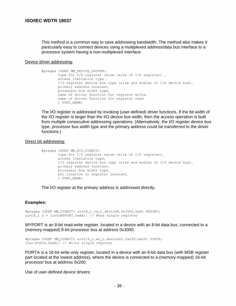
ISO/IEC WDTR 18037
- 38 -
This method is a common way to save addressing bandwidth. The method also makes itparticularly easy to connect devices using a multiplexed address/data bus interface to aprocessor system having a non-multiplexed interface.
Device driver addressing:
#pragma IODEF MM_DEVICE_DRIVER(type for I/O register value (size of I/O register) ,access limitation type ,I/O register device bus type (size and endian of I/O device bus),primary address constant,processor bus width type,name of driver function for register write,name of driver function for register read) PORT_NAME;
The I/O register is addressed by invoking (user-defined) driver functions. If the bit width ofthe I/O register is larger than the I/O device bus width, then the access operation is builtfrom multiple consecutive addressing operations. (Alternatively, the I/O register device bustype, processor bus width type and the primary address could be transferred to the driverfunctions.)
Direct bit addressing:
#pragma IODEF MM_BIT_DIRECT(type for I/O register value (size of I/O register),access limitation type,I/O register device bus type (size and endian of I/O device bus),primary address constant,processor bus width type,bit location in register constant,) PORT_NAME;
The I/O register at the primary address is addressed directly.
Examples:
#pragma IODEF MM_DIRECT( uint8_t,rw_t,device8,0x3000,bw8) MYPORT;uint8_t a = iord(MYPORT,0xAA); // Read single register
MYPORT is an 8-bit read-write register, located in a device with an 8-bit data bus, connected to a(memory-mapped) 8-bit processor bus at address 0x3000.
#pragma IODEF MM_DIRECT( uint16_t,wo_t,device8l,0x200,bw16) PORTA;iowr(PORTA,0xAA); // Write single register
PORTA is a 16-bit write-only register, located in a device with an 8-bit data bus (with MSB registerpart located at the lowest address), where the device is connected to a (memory-mapped) 16-bitprocessor bus at address 0x200.
Use of user-defined device drivers:

ISO/IEC WDTR 18037
- 39 -
// Memory buffer addressed via user-defined access drivers#pragma IODEF MM_DEVICE_DRIVER
<uint8_t,rmw_t,device8,0xA,my_wr_drv,my_rd_drv> DRVREG;
// User-defined read driver to be invoked by compilerinline uint8_t void my_rd_drv( int index )
{// some driver code}
// User-defined wr driver to be invoked by compilerinline void my_wr_drv( int index , uint8_t dat)
{// some driver code}
// user codeint i;i = iord(DRVREG); // = call of my_rd_drv(0xA);for (i = 0; i < 0xA0; i++) iowrbuf(DRVREG,i,0x0); // = call of my_wr_drv(i+0xA,0)
C.4 Parsing
The access specifications are parsed at compile time.
If the symbolic port name is used directly in iord(..) / iowr(..) / etc. functions, the code can becompletely optimised at compile time: all information for doing this is available to the compiler at thatstage. Based on the combined parameter set, the compiler will typically select among severalinternal intrinsic inline access functions to generate the appropriate code for the access operation.No memory instantiation of an access_spec object is needed. This will fulfil the third of the primaryrequirements in C.1.1 (no-overhead solution).
Example:#pragma IODEF MM_DIRECT(uint16_t,rmw,device8l,0x3456,bw16) MY_PORT1;uint16_t d;//...d = iord(MY_PORT1); // no-overhead in-line codeiowr(MY_PORT1, 0x456);
If the symbolic port name is referenced via a pointer, then an access_spec object must beinstantiated in memory; (slower) generic functions are invoked by the iord(..)/iowr(..)/etc. functions.In this case, the access_spec parameter is mostly evaluated at runtime. (This approach is similar tothe one used for extern inline functions in C)
Example:
#pragma IODEF MM_DIRECT(uint16_t,rmw_t,device8l,0x3456,bw16) MY_PORT1;#pragma IODEF MM_DIRECT(uint16_t,ro_t,device16l,0x7890,bw16) MY_PORT2;
uint16_t foo(MM_DIRECT * iop) { return iord(iop); // invoke some generic iord function

ISO/IEC WDTR 18037
- 40 -
}
uint16_t a;a = foo(MY_PORT1);a +=foo(MY_PORT2);
C.5 Comments on syntax no tation
The advantages with the proposed notation are: that it can be made reasonable consistent acrossprocessor and bus architectures, and (most importantly) it will be both fairly easy to comprehendand to use for the average embedded programmer. (In contrast to this are pure macro-basedimplementations, which tend to become rather complex to understand, create, and maintain for theuser.)
The header file which defines the hardware will look simple (typically, like a list, with one registerdefinition per text line). This makes it easy for a user to adapt an existing access_spec definition tonew hardware. Maintenance becomes much simpler.
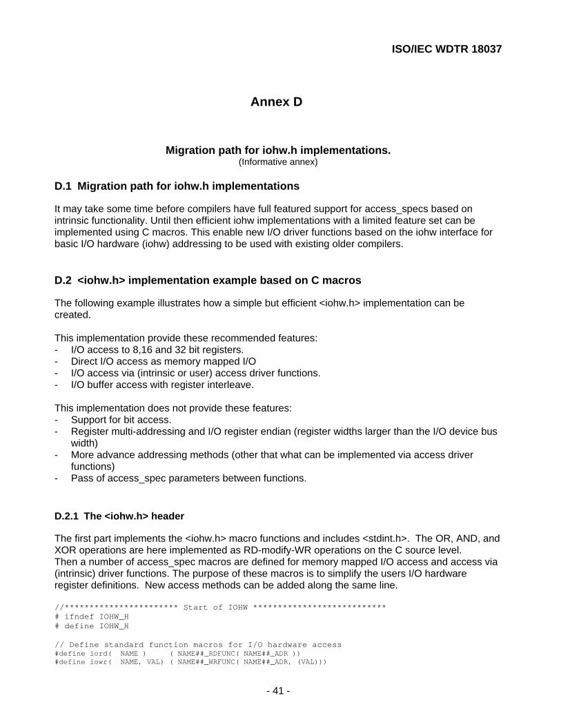
ISO/IEC WDTR 18037
- 41 -
Annex D
Migration pa th for iohw.h implementations .(Informative annex)
D.1 Migration path for iohw.h implementations
It may take some time before compilers have full featured support for access_specs based onintrinsic functionality. Until then efficient iohw implementations with a limited feature set can beimplemented using C macros. This enable new I/O driver functions based on the iohw interface forbasic I/O hardware (iohw) addressing to be used with existing older compilers.
D.2 <iohw.h> implementation exa mple based on C macros
The following example illustrates how a simple but efficient <iohw.h> implementation can becreated.
This implementation provide these recommended features:- I/O access to 8,16 and 32 bit registers.- Direct I/O access as memory mapped I/O- I/O access via (intrinsic or user) access driver functions.- I/O buffer access with register interleave.
This implementation does not provide these features:- Support for bit access.- Register multi-addressing and I/O register endian (register widths larger than the I/O device bus
width)- More advance addressing methods (other that what can be implemented via access driver
functions)- Pass of access_spec parameters between functions.
D.2.1 The <iohw.h> header
The first part implements the <iohw.h> macro functions and includes <stdint.h>. The OR, AND, andXOR operations are here implemented as RD-modify-WR operations on the C source level.Then a number of access_spec macros are defined for memory mapped I/O access and access via(intrinsic) driver functions. The purpose of these macros is to simplify the users I/O hardwareregister definitions. New access methods can be added along the same line.
//*********************** Start of IOHW ***************************# ifndef IOHW_H# define IOHW_H
// Define standard function macros for I/O hardware access#define iord( NAME ) ( NAME##_RDFUNC( NAME##_ADR ))#define iowr( NAME, VAL) ( NAME##_WRFUNC( NAME##_ADR, (VAL)))

ISO/IEC WDTR 18037
- 42 -
#define ioor( NAME, VAL) ( NAME##_WRFUNC( NAME##_ADR, (NAME##_RDFUNC(NAME##_ADR) | ( VAL ))))#define ioand( NAME, VAL) ( NAME##_WRFUNC( NAME##_ADR, (NAME##_RDFUNC(NAME##_ADR) & ( VAL ))))#define ioxor( NAME, VAL) ( NAME##_WRFUNC( NAME##_ADR, (NAME##_RDFUNC(NAME##_ADR) ^ ( VAL ))))
#define iordbuf( NAME, INDEX ) ( NAME##_RDFUNC( NAME##_ADR+(INDEX)*NAME##_INTL))#define iowrbuf( NAME, INDEX, VAL) ( NAME##_WRFUNC( NAME##_ADR+(INDEX)*NAME##_INTL, (VAL)))#define ioorbuf( NAME, INDEX, VAL) ( NAME##_WRFUNC( NAME##_ADR+(INDEX)*NAME##_INTL,\ (NAME##_RDFUNC( NAME##_ADR+(INDEX)*NAME##_INTL) | ( VAL ))))#define ioandbuf( NAME, INDEX, VAL) ( NAME##_WRFUNC( NAME##_ADR+(INDEX)*NAME##_INTL, \ (NAME##_RDFUNC( NAME##_ADR+(INDEX)*NAME##_INTL) & ( VAL ))))#define ioxorbuf( NAME, INDEX, VAL) ( NAME##_WRFUNC( NAME##_ADR+(INDEX)*NAME##_INTL, \ (NAME##_RDFUNC( NAME##_ADR+(INDEX)*NAME##_INTL) ^ ( VAL ))))
#define io_at_init( NAME ) NAME##_INIT#define io_at_release( NAME ) NAME##_RELEASE// the only dynamic access_spec parameter in this implementation is the address#define io_at_cpy( DNAME, SNAME ) ((DNAME##_ADR) = (SNAME##_ADR))
// Include standard integer type definitions similar to:// #define uint8_t unsigned char// #define uint16_t unsigned short// #define uint32_t unsigned long#include <stdint.h>
// Some access_spec macros which simplify the users access_specs definitions// These macros are platform specific (intrinsic)// There should be one definition for each addressing range, register width and// access method supported
// Some access macros for simple memory mapped I/O#define RDPTR8(address) (* (volatile uint8_t *) ( address ))#define WRPTR8(address,val) ((* (volatile uint8_t *) ( address )) = (uint8_t)(val))#define RDPTR16(address) (* (volatile uint16_t *) ( address ))#define WRPTR16(address,val) ((* (volatile uint16_t *) ( address )) = (uint16_t)(val))#define RDPTR32(address) (* (volatile uint32_t *) ( address ))#define WRPTR32(address,val) ((* (volatile uint32_t *) ( address )) = (uint32_t)(val))
// Some access macros for access via (intrinsic) I/O hardware access functions#define RDFUNC8(address) (_inp( (uint16_t)(address)))#define WRFUNC8(address,val) (_outp( (uint16_t)(address),(uint8_t)(val)))#define RDFUNC16(address) (_inpw( (uint16_t)(address)))#define WRFUNC16(address,val) (_outpw((uint16_t)(address),(uint16_t)(val)))#define RDFUNC32(address) (_inpd( (uint16_t)(address)))#define WRFUNC32(address,val) (_outpd((uint16_t)(address),(uint32_t)(val)))
// Prototype for the (intrinsic) I/O hardware access functionsuint8_t _inp( uint16_t adr);uint16_t _inpw( uint16_t adr);uint32_t _inpd( uint16_t adr);void _outp( uint16_t adr, uint8_t val);void _outpw(uint16_t adr, uint16_t val);void _outpd(uint16_t adr, uint32_t val);
# endif//*********************** End of IOHW ***************************

ISO/IEC WDTR 18037
- 43 -
D.2.2 The users I/O register definitions
For each I/O register (each symbolic name) a complete definition of the access method must becreated. With this iohw implementation the user must define:- The access method for RD and/or WR operations (which also define the register size and select
between memory mapped I/O or access via driver functions).- The I/O register address- The interleave factor for register arrays.
These platform dependent I/O register definitions are normally placed in a separate header file.Here called <iohw_ta.h>.
//****** Start of user I/O register definitions (IOHW_TA.H) ******#ifndef IOHW_TA#define IOHW_TA
#define MYPORTS_INIT {/* No initialization needed in this system */}#define MYPORTS_RELEASE {/* No release needed in this system */}
// REG_A register is accessed via a base addressextern uint16_t base_adr; // is placed in some platform dependent C module#define REG_A_ADR base_adr#define REG_A_WRFUNC WRFUNC8#define REG_A_RDFUNC RDFUNC8
// MYPORT1 is a bidirectional memory mapped register#define MYPORT1_ADR 0x1234 // Defines physical address#define MYPORT1_WRFUNC WRPTR8 // Defines access method, bus type and register size#define MYPORT1_RDFUNC RDPTR8
// MYPORT2 is a write-only memory mapped register// iord(),ioor(),ioand(),ioxor() will produce a compiler warning#define MYPORT2_ADR 0x4567#define MYPORT2_WRFUNC WRPTR16 // Only write operations is defined
// MYPORT3 is a read-only memory mapped register// iowr(),ioor(),ioand(),ioxor() will produce a compiler warning#define MYPORT3_ADR 0x7870#define MYPORT3_RDFUNC RDPTR16 // Only read operations is defined
// MYPORT4 is a bidirectional port accessed via (intrinsic) driver functions#define MYPORT4_ADR 0x12#define MYPORT4_WRFUNC WRFUNC8#define MYPORT4_RDFUNC RDFUNC8
// MYPORT5 is a bidirectional memory mapped register array#define MYPORT5_ADR 0x1234 // Defines physical address#define MYPORT5_WRFUNC WRPTR8 // Defines access method, bus type and register size#define MYPORT5_RDFUNC RDPTR8#define MYPORT5_INTL 2 // 16 bit processor bus / 8 bit I/O device bus
// MYPORT6 is yet another register of the same type as MYPORT4#define MYPORT6_ADR 0x234#define MYPORT6_WRFUNC WRFUNC8#define MYPORT6_RDFUNC RDFUNC8#endif//************ End of user I/O register definitions ********************

ISO/IEC WDTR 18037
- 44 -
D.2.3 The driver function
The driver function should include <iohw.h> and the user I/O register definitions for the targetsystem <iohw_ta.h>. The example below tests all operations on all the previous I/O registerdefinitions.Note that illegal I/O register access operations in the driver code will be detected at compile time ex.read of a write-only register or write of a read-only register.
#include <iohw.h> // includes stdint.h#include <iohw_ta.h> // My register definitions
uint8_t cdat;uint16_t idat;
uint16_t my_func(void) { uint16_t t = (uint16_t) iord(REG_A); iowr(REG_A,0x80); return t; }
void my_test_driver (void) { io_at_init(MYPORTS);
// Test bidirectional memory mapped I/O port cdat = iord(MYPORT1); iowr(MYPORT1,0x12); iowr(MYPORT1,cdat); ioor(MYPORT1, 0x23); ioand(MYPORT1,0x34); ioxor(MYPORT1,0xf0);
// Test unidirectional I/O ports iowr(MYPORT2,0x3455); idat = iord(MYPORT3);
// Test bidirectional I/O register accessed via functions cdat = iord(MYPORT4); iowr(MYPORT4,0x12); iowr(MYPORT4,cdat); ioor(MYPORT4, 0x23); ioand(MYPORT4,0x34); ioxor(MYPORT4,0xf0);
// Test buffer functions cdat = iordbuf(MYPORT5,20); iowrbuf(MYPORT5,43,0x12); ioorbuf(MYPORT5,43,0x12); ioandbuf(MYPORT5,43,0x02); ioxorbuf(MYPORT5,43,0x12);
// These statements will produce compiler warnings // idat = iord(MYPORT2); // Error write-only port // iowr(MYPORT3,4565); // Error read-only port
// REG_A, MYPORT4 and MYPORT6 must be of the same type io_at_cpy(REG_A, MYPORT4);

ISO/IEC WDTR 18037
- 45 -
idat = my_func(); // Access MYPORT4 via driver io_at_cpy(REG_A, MYPORT6); idat = my_func(); // Access MYPORT6 via driver io_at_release(MYPORTS); }
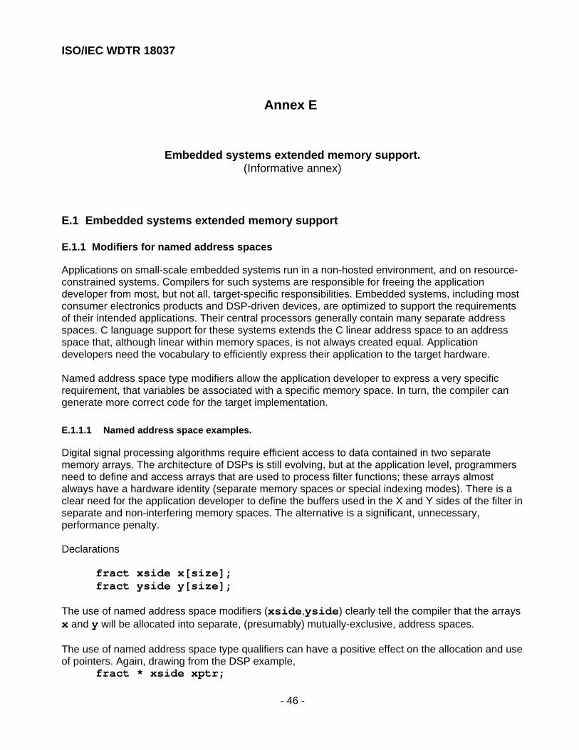
ISO/IEC WDTR 18037
- 46 -
Annex E
Embedded s ystems extended memory suppo rt.(Informative annex)
E.1 Embedded systems extended memory suppo rt
E.1.1 Modifiers for named address s paces
Applications on small-scale embedded systems run in a non-hosted environment, and on resource-constrained systems. Compilers for such systems are responsible for freeing the applicationdeveloper from most, but not all, target-specific responsibilities. Embedded systems, including mostconsumer electronics products and DSP-driven devices, are optimized to support the requirementsof their intended applications. Their central processors generally contain many separate addressspaces. C language support for these systems extends the C linear address space to an addressspace that, although linear within memory spaces, is not always created equal. Applicationdevelopers need the vocabulary to efficiently express their application to the target hardware.
Named address space type modifiers allow the application developer to express a very specificrequirement, that variables be associated with a specific memory space. In turn, the compiler cangenerate more correct code for the target implementation.
E.1.1.1 Named address space examples.
Digital signal processing algorithms require efficient access to data contained in two separatememory arrays. The architecture of DSPs is still evolving, but at the application level, programmersneed to define and access arrays that are used to process filter functions; these arrays almostalways have a hardware identity (separate memory spaces or special indexing modes). There is aclear need for the application developer to define the buffers used in the X and Y sides of the filter inseparate and non-interfering memory spaces. The alternative is a significant, unnecessary,performance penalty.
Declarations
fract xside x[size];fract yside y[size];
The use of named address space modifiers (xside,yside) clearly tell the compiler that the arraysx and y will be allocated into separate, (presumably) mutually-exclusive, address spaces.
The use of named address space type qualifiers can have a positive effect on the allocation and useof pointers. Again, drawing from the DSP example,
fract * xside xptr;

ISO/IEC WDTR 18037
- 47 -
Such a declaration describes a pointer that is limited to accessing data located in the xsidememory area. The xptr declaration gives the compiler the option of using shorter references.
E.1.1.2 Embedded system examples
Embedded systems generally support three or four address spaces: execution memory, generalpurpose random access memory, input/output access, and sometimes a fast random accessmemory. These address spaces are normally supported by the compiler, and the names assignedwould be implementation- and target-specific. Different compiler implementations targeting thesame processors would normally support the same set of multiple address spaces.
Embedded systems often require user-defined address spaces, to support C-language access tosoftware-driven resources. Examples include external data RAM and non-volatile memory, both ofwhich are often connected through a software-driven bus.
E.1.2 User-defined device drivers
Many embedded systems include memory that can only be accessed with some form of devicedriver. These include memories accessed by serial data busses (I2C, SPI), and on-boardnon-volatile memory that must be programmed under software control. Device-driver memorysupport is used in applications where the details of the access method can be separated from thedetails of the application.
In contrast to memory-mapped I/O, the extended memory layout and its use should beadministrated by the compiler/linker.Language support for embedded systems needs to address the following issues:
1) Memory with user-defined device drivers. User-defined device drivers are required forreading and writing user-defined memory.• Memory-read functions take as an argument an address in the user-defined memory
space, and return data of a user-defined size.• Memory-write functions take two arguments, an address in the user-defined memory
space and data with a user-specified size. (note re: any return value?)• Applications require support for multiple user-defined address spaces.• User-defined memory areas may not be contiguous. Most of the applications have
gaps in the addressing within user-defined memory areas.2) The compiler is responsible for:
• Allocating variables, according to the needs of the application, in "normal" addressspace, and in space accessed by the user-defined memory device drivers.
• Making calls to device drivers, when accessing variables supported by user-defineddevice drivers.
• Automating the process of casting and accessing the data, between calls to accessdata and the application.
3) Application variables in user-defined memory areas :• Need to support all of the available data types. For example, declarations for
fundamental data types, arrays, structures.• Users need to direct the compiler to use a specific memory area.
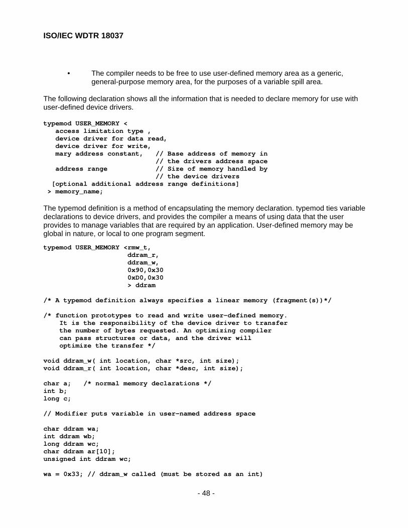
ISO/IEC WDTR 18037
- 48 -
• The compiler needs to be free to use user-defined memory area as a generic,general-purpose memory area, for the purposes of a variable spill area.
The following declaration shows all the information that is needed to declare memory for use withuser-defined device drivers.
typemod USER_MEMORY < access limitation type , device driver for data read, device driver for write, mary address constant, // Base address of memory in // the drivers address space address range // Size of memory handled by // the device drivers [optional additional address range definitions] > memory_name;
The typemod definition is a method of encapsulating the memory declaration. typemod ties variabledeclarations to device drivers, and provides the compiler a means of using data that the userprovides to manage variables that are required by an application. User-defined memory may beglobal in nature, or local to one program segment.
typemod USER_MEMORY <rmw_t, ddram_r, ddram_w, 0x90,0x30 0xD0,0x30 > ddram
/* A typemod definition always specifies a linear memory (fragment(s))*/
/* function prototypes to read and write user-defined memory. It is the responsibility of the device driver to transfer the number of bytes requested. An optimizing compiler can pass structures or data, and the driver will optimize the transfer */
void ddram_w( int location, char *src, int size);void ddram_r( int location, char *desc, int size);
char a; /* normal memory declarations */int b;long c;
// Modifier puts variable in user-named address space
char ddram wa;int ddram wb;long ddram wc;char ddram ar[10];unsigned int ddram wc;
wa = 0x33; // ddram_w called (must be stored as an int)

ISO/IEC WDTR 18037
- 49 -
a = wa; // ddram_r called once, MSB turncatedb = wb; // ddram_r called oncec = wc; // ddram_r called more than once (implementation defined)

ISO/IEC WDTR 18037
- 50 -
Annex F
Func tionalit y no t inc luded in this Techn ical Report.(Informative annex)
F.1 Circu lar buffers
The concept of circular buffers is widely used within the signal processing community. An exampleof the use of the concept of circular buffers is in a FIR filter, where it is used to reduce the number ofmemory accesses. The functionality of a FIR filter can described in this way with current C:
int x[N+1]; // data valuesint h[N+1]; // coefficient valueslong int accu = 0;
x[0] = new_value;
accu = x[N] * h[N];
for(i=N-1; i>0; i--){ accu += (long int) x[i] * h[i]; x[i]= x[i-1];}
The datavalue copy in the last statement in the for loop would be unnecessary, if the concept of acircular buffer was employed here, reducing the number of memory accesses. Many digital signalprocessors have direct support in their addressing hardware to provide zero-overhead circularaddressing. Zero-overhead means here that calculating the address for an access to a circularbuffer can be done in the same time as performing a regular address calculation, including thewrap-around check and, if necessary, the execution of the wrap-around. However there are oftenmany restrictions on how hardware supported circular addressing can be used. E.g., only addressincrements by one are allowed in some implementations, and there may be requirements to the sizeand/or alignment of the buffer.
Since the functional specifications of the support for circular addressing in various processors is sodivers, it is difficult to define an abstract model that can be used in a natural manner in theC language, and that also can be translated efficiently for the various hardware paradigms.Therefore, in this Technical Report no proposals are made for language extensions to supportcircular buffers. Should, in the future, a single approach towards circular addressing becomedominant in the market, then an appropriate C language construct could be defined.

ISO/IEC WDTR 18037
- 51 -
Some current approaches to circular addressing are given below.- Add a new keyword (for instance, circ) to the C language, that allows a programmer to
indicate that an array or pointer with this qualifier is to be accessed with circular addressing.- Another solution is to define a new library function or macro, CIRC(), which could be used in the
following manner:int *p;
p = CIRC(p+1, /* array info */);// this does an increment by one of p
Array info in this example covers the starting address and end address of the address rangewhere circular addressing is desired. A compiler for an architecture that has direct hardwaresupport for circular addressing is then free to optimize this function call away, and exploit thecapabilities of the hardware.
- In the current C language there is provision to specify circular buffers, however only when usingarray index notation:
accum += (long int) x[i % N]*h[i];It is possible for a clever optimizer to recognize that this in fact is a circular buffer and exploit thehardware support for this. This has the advantage that the use of circular buffers is alreadypossible within the current C language, but it requires the programmer to use array indicesrather than pointers. Furthermore it is not possible to specify any alignment constraint on theallocated buffer, which might be necessary for the underlying hardware implementation.
No preferred solution is specified here.
F.2 Complex data types
In this Technical Report no complex fixed point datatypes are been defined. However in C complexdatatypes are already existing for floating point numbers. As fract and accum types can beviewed upon as an alternative to floating-point numbers in some applications it is worthwhileconsidering extending the definition of complex types in C to include fract and accum bases. It willbe beneficial for the user community to standardize such data types as they have a clear usage inan area like communications signal processing.