isolated power supplies for plc i/o modules - ti training 14... · isolated power supplies for plc...
TRANSCRIPT
Isolated Power Supplies for PLC I/O Modules
Tobias Puetz, Systems Engineer
Industrial Systems
1

Agenda
• PLC I/O Modules
• Isolated Power Topologies
• Fly-Buck
• Fly-Buck-Boost
• Design Examples and Resources
2
PLC I/O Modules
Types
Power Requirements
Why Isolation Is Necessary
3

PLC I/O Modules Types
4
Module Types
• Analog Input / Output
• Digital Input / Output
• Special Function
• Transducer
PLC I/O Modules Power Requirements
5
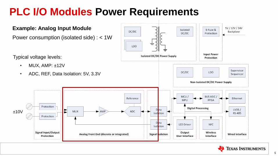
Example: Analog Input Module
Power consumption (isolated side) : < 1W
Typical voltage levels:
• MUX, AMP: ±12V
• ADC, REF, Data Isolation: 5V, 3.3V
±10V
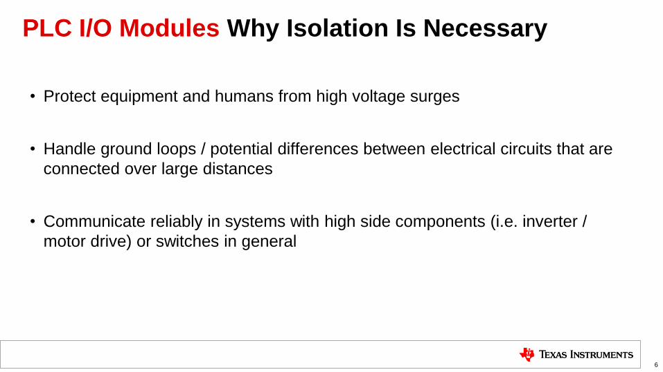
PLC I/O Modules Why Isolation Is Necessary
• Protect equipment and humans from high voltage surges
• Handle ground loops / potential differences between electrical circuits that are
connected over large distances
• Communicate reliably in systems with high side components (i.e. inverter /
motor drive) or switches in general
6
Isolated Power Topologies for PLC I/O Modules
Push-Pull
Fly-Back
Fly-Buck
7
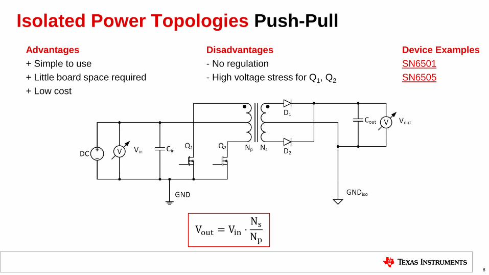
Isolated Power Topologies Push-Pull
Advantages Disadvantages Device Examples
+ Simple to use - No regulation SN6501
+ Little board space required - High voltage stress for Q1, Q2 SN6505
+ Low cost
8
Vout = Vin ⋅Ns
Np
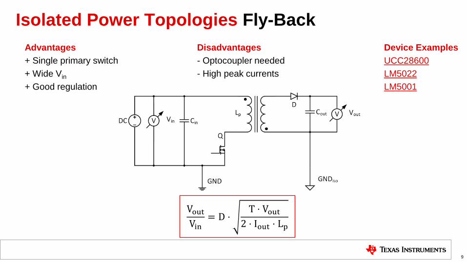
Isolated Power Topologies Fly-Back
Advantages Disadvantages Device Examples
+ Single primary switch - Optocoupler needed UCC28600
+ Wide Vin - High peak currents LM5022
+ Good regulation LM5001
9
Vout
Vin= D ⋅
T ⋅ Vout
2 ⋅ Iout ⋅ Lp
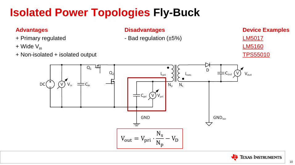
Isolated Power Topologies Fly-Buck
Advantages Disadvantages Device Examples
+ Primary regulated - Bad regulation (±5%) LM5017
+ Wide Vin LM5160
+ Non-isolated + isolated output TPS55010
10
Vout = Vpri ⋅Ns
Np− VD

Fly-Buck
Topology
Working Principle
Things to Consider
11

Fly-Buck Topology
12
+
N =Ns
Np
Vpri = Vin ⋅ D = Vin ⋅ton
ton + toff
⇒ Vout= Vpri ⋅ N − VD

Fly-Buck Working Principle
13
• ton - Q1 closed, Q2 open: • Current flows through Lpri
• Diode D is reversed biased
• No current flowing on sec. side
• toff - Q1 open, Q2 closed: • Voltage across Lpri and Lsec
reverses
• Current flowing
Vin
Vsec
-N*(Vin-Vpri)
Vsw
VD
Ton Toff
t
t0V
0V
N*Vpri
I0,sec
I0,pri
Ipri
Isec
t
Ton Toff
t0A
0A
Ipri
Vsw
Isec
VD N =Ns
Np
=> Device needs to support forced PWM mode!

Fly-Buck Things to Consider – Duty Cycle
14
High duty cycle => short energy transfer time
Low duty cycle => short energy charge time
Bad output voltage regulation because of high peak
currents on primary or secondary side
I0,sec
I0,pri
Ipri
Isec
t
Ton Toff
t0A
0A
Ipri ⋅ ton = Isec ⋅ toff ⋅ N
Ipri = Isec ⋅ N ⋅1 − D
D
D =ton
ton + toff
0
2
4
6
8
10
0 0.2 0.4 0.6 0.8 1
D
Ipri
Isec N=1
Ipri Isec
N =Ns
Np
Choose D between 40% and 60%
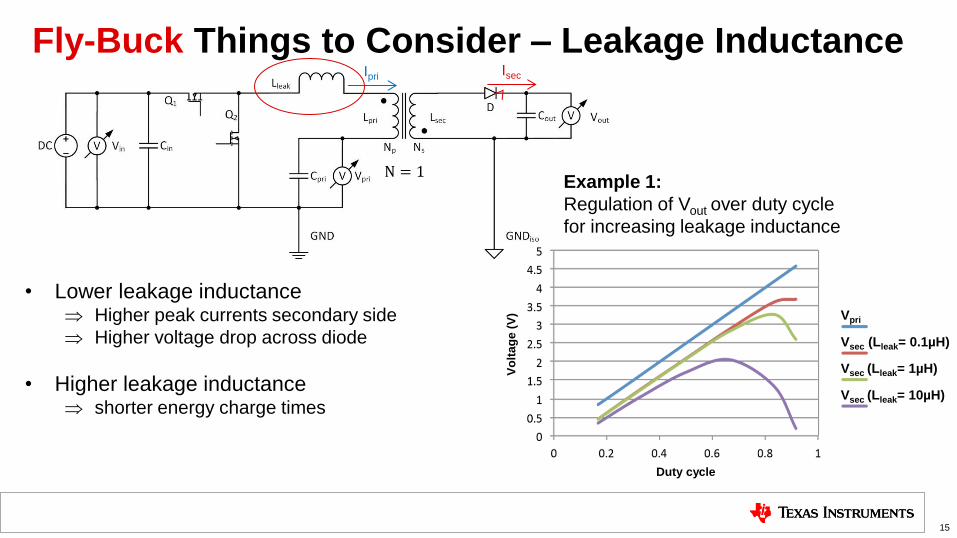
Fly-Buck Things to Consider – Leakage Inductance
15
• Lower leakage inductance Higher peak currents secondary side
Higher voltage drop across diode
• Higher leakage inductance shorter energy charge times
Example 1:
Regulation of Vout over duty cycle
for increasing leakage inductance
Duty cycle
Vo
lta
ge
(V
)
N = 1
Vpri
Vsec (Lleak= 0.1µH)
Vsec (Lleak= 1µH)
Vsec (Lleak= 10µH)
Ipri Isec

Fly-Buck Things to Consider – Leakage Inductance
16
• Lower leakage inductance Higher peak currents secondary side
Higher voltage drop across diode
• Higher leakage inductance shorter energy charge times
Example 2:
Peak currents of Isec voltage for
different leakage inductances
N = 1
Ipri Isec

Fly-Buck-Boost
Topology
Fly-Buck Comparison
17

Fly-Buck-Boost Topology
−Vpri= Vin ⋅ton
toff= Vin ⋅
D
1 − D Vout = −Vpri ⋅ N − VD
18
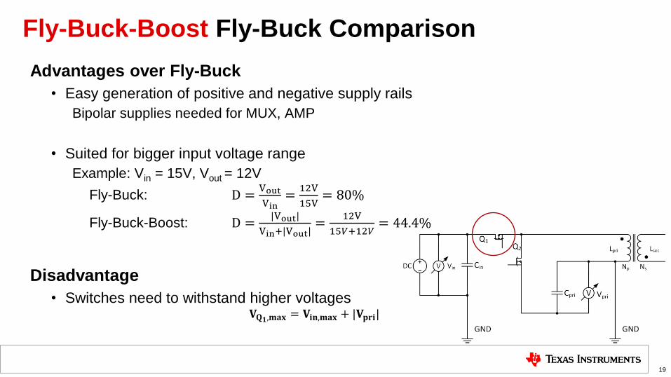
Fly-Buck-Boost Fly-Buck Comparison
Advantages over Fly-Buck
• Easy generation of positive and negative supply rails
Bipolar supplies needed for MUX, AMP
• Suited for bigger input voltage range
Example: Vin = 15V, Vout = 12V
Fly-Buck: D =Vout
Vin=
12V
15V= 80%
Fly-Buck-Boost: D =|Vout|
Vin+|Vout|=
12V
15𝑉+12𝑉= 44.4%
Disadvantage
• Switches need to withstand higher voltages 𝐕𝐐𝟏,𝐦𝐚𝐱 = 𝐕𝐢𝐧,𝐦𝐚𝐱 + |𝐕𝐩𝐫𝐢|
19
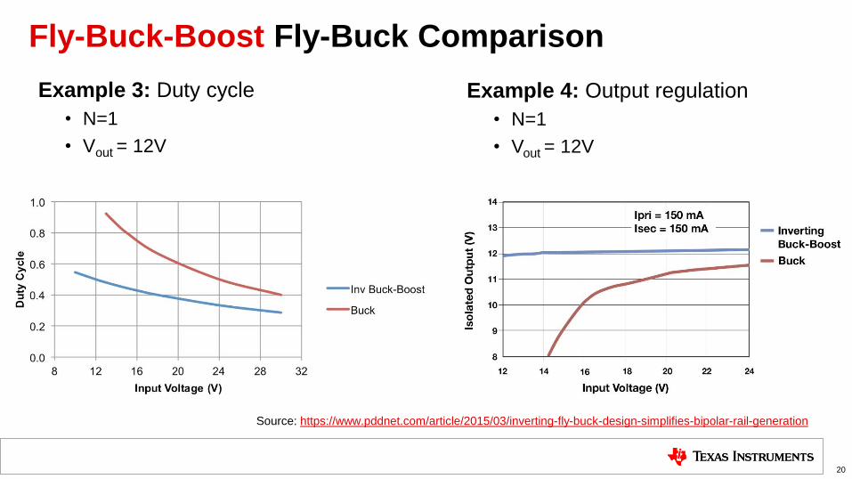
Fly-Buck-Boost Fly-Buck Comparison
20
Example 3: Duty cycle
• N=1
• Vout = 12V
Example 4: Output regulation
• N=1
• Vout = 12V
Source: https://www.pddnet.com/article/2015/03/inverting-fly-buck-design-simplifies-bipolar-rail-generation

Designs and Resources
TI Desings
PMPs
Application Notes
Links
21
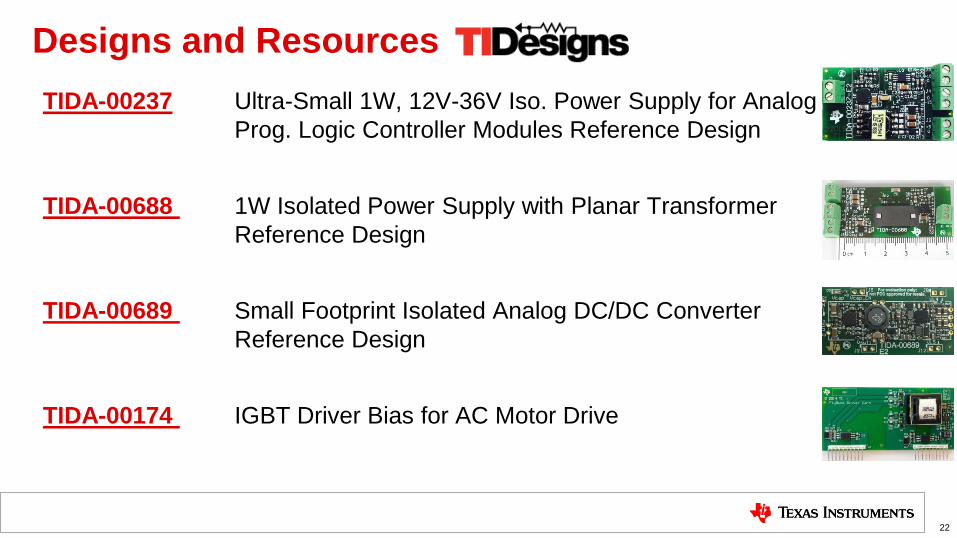
TIDA-00237 Ultra-Small 1W, 12V-36V Iso. Power Supply for Analog
Prog. Logic Controller Modules Reference Design
TIDA-00688 1W Isolated Power Supply with Planar Transformer
Reference Design
TIDA-00689 Small Footprint Isolated Analog DC/DC Converter
Reference Design
TIDA-00174 IGBT Driver Bias for AC Motor Drive
22
Designs and Resources
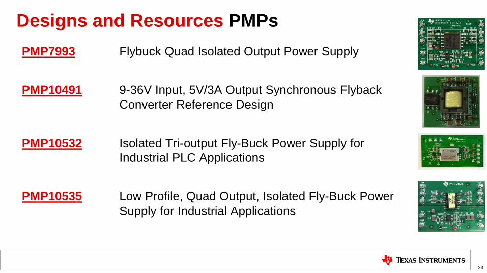
Designs and Resources PMPs
PMP7993 Flybuck Quad Isolated Output Power Supply
PMP10491 9-36V Input, 5V/3A Output Synchronous Flyback
Converter Reference Design
PMP10532 Isolated Tri-output Fly-Buck Power Supply for
Industrial PLC Applications
PMP10535 Low Profile, Quad Output, Isolated Fly-Buck Power
Supply for Industrial Applications
23

Designs and Resources Application Notes
Fly-Buck(TM) converter provides EMC and isolation in PLC applications
AN-2292 Designing an Isolated Buck (Fly-Buck) Converter (Rev. C)
Design a Flybuck Solution with Optocoupler to Improve Regulation Performance
Designing isolated rails on the fly with Fly-Buck™ converters
24

Designs and Resources Links
www.ti.com/automation
www.ti.com/flybuck
www.ti.com/flyback
25

Questions and Answers
26