it . s801 soft starter - elektrosistemelektrosistem.ba/uputstva/s801 soft starter - user...
TRANSCRIPT

MN03902008E For more information visit:
www.EatonElectrical.com
IT
. S801 Soft Starter
User Manual
June 2006Supersedes July 2002 — Pub 49003, Rev. L


IT
. S801 Soft Starter User Manual
MN03902008E For more information visit:
www.EatonElectrical.com
i
June 2006
Important Notice — Please Read
The product discussed in this literature is subject to terms and conditions outlined in Eaton Electrical Inc. selling policies. The sole source governing the rights and remedies of any purchaser of this equipment is the relevant Eaton Electrical Inc. selling policy.
NO WARRANTIES, EXPRESS OR IMPLIED, INCLUDING WARRANTIES OF FITNESS FOR A PARTICULAR PURPOSE OR MERCHANTABILITY, OR WARRANTIES ARISING FROM COURSE OF DEALING OR USAGE OF TRADE, ARE MADE REGARDING THE INFORMATION, RECOMMENDATIONS AND DESCRIPTIONS CONTAINED HEREIN. In no event will Eaton Electrical Inc. be responsible to the purchaser or user in contract, in tort (including negligence), strict liability or otherwise for any special, indirect, incidental or consequential damage or loss whatsoever, including but not limited to damage or loss of use of equipment, plant or power system, cost of capital, loss of power, additional expenses in the use of existing power facilities, or claims against the purchaser or user by its customers resulting from the use of the information, recommendations and descriptions contained herein.
The information contained in this manual is subject to change without notice.
Cover Photo: The Cutler-Hammer
®
Intelligent Technology S801 Soft Starter Family
IT
. S801 Soft Starter User Manual
ii
For more information visit:
www.EatonElectrical.com
MN03902008E
June 2006
Table of Contents
LIST OF FIGURES
. . . . . . . . . . . . . . . . . . . . . . . . . . . . . . . . . . . . . . . . . . . . . . . . . . . . . . . . . iv
LIST OF TABLES
. . . . . . . . . . . . . . . . . . . . . . . . . . . . . . . . . . . . . . . . . . . . . . . . . . . . . . . . . . v
SAFETY
The Meaning of Safety Statements . . . . . . . . . . . . . . . . . . . . . . . . . . . . . . . . . . . . . . vi
IT.
Soft Starter Safety Statements . . . . . . . . . . . . . . . . . . . . . . . . . . . . . . . . . . . . . . . viiDangers, Warnings, Cautions and Notes . . . . . . . . . . . . . . . . . . . . . . . . . . . . . . . . . . viii
CHAPTER 1 — OVERVIEW
General Introduction . . . . . . . . . . . . . . . . . . . . . . . . . . . . . . . . . . . . . . . . . . . . . . . . . . 1-1General Appearance Notes . . . . . . . . . . . . . . . . . . . . . . . . . . . . . . . . . . . . . . . . . . . . . 1-2
CHAPTER 2 — RECEIPT/UNPACKING
General . . . . . . . . . . . . . . . . . . . . . . . . . . . . . . . . . . . . . . . . . . . . . . . . . . . . . . . . . . . . . 2-1Unpacking . . . . . . . . . . . . . . . . . . . . . . . . . . . . . . . . . . . . . . . . . . . . . . . . . . . . . . . . . . . 2-1Storage . . . . . . . . . . . . . . . . . . . . . . . . . . . . . . . . . . . . . . . . . . . . . . . . . . . . . . . . . . . . . 2-1
CHAPTER 3 — INSTALLATION
Mounting. . . . . . . . . . . . . . . . . . . . . . . . . . . . . . . . . . . . . . . . . . . . . . . . . . . . . . . . . . . . 3-1Power Wiring . . . . . . . . . . . . . . . . . . . . . . . . . . . . . . . . . . . . . . . . . . . . . . . . . . . . . . . . 3-8Control Wiring Inputs. . . . . . . . . . . . . . . . . . . . . . . . . . . . . . . . . . . . . . . . . . . . . . . . . . 3-11
CHAPTER 4 — SPECIFICATIONS
Environmental . . . . . . . . . . . . . . . . . . . . . . . . . . . . . . . . . . . . . . . . . . . . . . . . . . . . . . . 4-1Physical . . . . . . . . . . . . . . . . . . . . . . . . . . . . . . . . . . . . . . . . . . . . . . . . . . . . . . . . . . . . . 4-1CE Conformance. . . . . . . . . . . . . . . . . . . . . . . . . . . . . . . . . . . . . . . . . . . . . . . . . . . . . . 4-2Short Circuit Ratings . . . . . . . . . . . . . . . . . . . . . . . . . . . . . . . . . . . . . . . . . . . . . . . . . . 4-3
CHAPTER 5 — FUNCTIONAL DESCRIPTION
Power . . . . . . . . . . . . . . . . . . . . . . . . . . . . . . . . . . . . . . . . . . . . . . . . . . . . . . . . . . . . . . 5-1Control. . . . . . . . . . . . . . . . . . . . . . . . . . . . . . . . . . . . . . . . . . . . . . . . . . . . . . . . . . . . . . 5-1
CHAPTER 6 — CONFIGURATION
Programming the S801 . . . . . . . . . . . . . . . . . . . . . . . . . . . . . . . . . . . . . . . . . . . . . . . . 6-1Trip Class. . . . . . . . . . . . . . . . . . . . . . . . . . . . . . . . . . . . . . . . . . . . . . . . . . . . . . . . . . . . 6-2Protective Features. . . . . . . . . . . . . . . . . . . . . . . . . . . . . . . . . . . . . . . . . . . . . . . . . . . . 6-2Manual/Auto Fault Reset . . . . . . . . . . . . . . . . . . . . . . . . . . . . . . . . . . . . . . . . . . . . . . . 6-2Special Function S.F. . . . . . . . . . . . . . . . . . . . . . . . . . . . . . . . . . . . . . . . . . . . . . . . . . . 6-3Options . . . . . . . . . . . . . . . . . . . . . . . . . . . . . . . . . . . . . . . . . . . . . . . . . . . . . . . . . . . . . 6-3Programming the Start . . . . . . . . . . . . . . . . . . . . . . . . . . . . . . . . . . . . . . . . . . . . . . . . 6-3
CHAPTER 7 — SETUP AND STARTING
Line Power . . . . . . . . . . . . . . . . . . . . . . . . . . . . . . . . . . . . . . . . . . . . . . . . . . . . . . . . . . 7-1Jog. . . . . . . . . . . . . . . . . . . . . . . . . . . . . . . . . . . . . . . . . . . . . . . . . . . . . . . . . . . . . . . . . 7-1
CHAPTER 8 — TROUBLESHOOTING
General . . . . . . . . . . . . . . . . . . . . . . . . . . . . . . . . . . . . . . . . . . . . . . . . . . . . . . . . . . . . . 8-1Before You Begin to Troubleshoot . . . . . . . . . . . . . . . . . . . . . . . . . . . . . . . . . . . . . . . 8-1Define the Problem . . . . . . . . . . . . . . . . . . . . . . . . . . . . . . . . . . . . . . . . . . . . . . . . . . . 8-2
CHAPTER 9 — PARTS AND SERVICE
Renewal Parts . . . . . . . . . . . . . . . . . . . . . . . . . . . . . . . . . . . . . . . . . . . . . . . . . . . . . . . . 9-1Service. . . . . . . . . . . . . . . . . . . . . . . . . . . . . . . . . . . . . . . . . . . . . . . . . . . . . . . . . . . . . . 9-1

IT
. S801 Soft Starter User Manual
MN03902008E For more information visit:
www.EatonElectrical.com
iii
June 2006
Table of Contents, Continued
CHAPTER A — PROTECTION
Thermal Overload . . . . . . . . . . . . . . . . . . . . . . . . . . . . . . . . . . . . . . . . . . . . . . . . . . . . . A-1Overload Trip Curves . . . . . . . . . . . . . . . . . . . . . . . . . . . . . . . . . . . . . . . . . . . . . . . . . . A-2Jam Detection . . . . . . . . . . . . . . . . . . . . . . . . . . . . . . . . . . . . . . . . . . . . . . . . . . . . . . . . A-4Stall Detection . . . . . . . . . . . . . . . . . . . . . . . . . . . . . . . . . . . . . . . . . . . . . . . . . . . . . . . . A-5Phase Loss/Current Unbalance Detection and Load Disconnect. . . . . . . . . . . . . . . . A-5Phase Reversal Detection . . . . . . . . . . . . . . . . . . . . . . . . . . . . . . . . . . . . . . . . . . . . . . . A-5Protective Features Review . . . . . . . . . . . . . . . . . . . . . . . . . . . . . . . . . . . . . . . . . . . . . A-6
CHAPTER B — RATINGS, COOLING AND POWER LOSSES
Horsepower and kW Ratings . . . . . . . . . . . . . . . . . . . . . . . . . . . . . . . . . . . . . . . . . . . . B-1Cooling . . . . . . . . . . . . . . . . . . . . . . . . . . . . . . . . . . . . . . . . . . . . . . . . . . . . . . . . . . . . . . B-8Power Losses . . . . . . . . . . . . . . . . . . . . . . . . . . . . . . . . . . . . . . . . . . . . . . . . . . . . . . . . . B-8
CHAPTER C — MOTOR/APPLICATION CONSIDERATIONS
Using MOVs. . . . . . . . . . . . . . . . . . . . . . . . . . . . . . . . . . . . . . . . . . . . . . . . . . . . . . . . . . C-1Squirrel Cage Motor . . . . . . . . . . . . . . . . . . . . . . . . . . . . . . . . . . . . . . . . . . . . . . . . . . . C-1Wye-Delta Motor . . . . . . . . . . . . . . . . . . . . . . . . . . . . . . . . . . . . . . . . . . . . . . . . . . . . . . C-2Part Winding Motor. . . . . . . . . . . . . . . . . . . . . . . . . . . . . . . . . . . . . . . . . . . . . . . . . . . . C-2Dual Voltage Motor . . . . . . . . . . . . . . . . . . . . . . . . . . . . . . . . . . . . . . . . . . . . . . . . . . . . C-2Multi-Speed Motor . . . . . . . . . . . . . . . . . . . . . . . . . . . . . . . . . . . . . . . . . . . . . . . . . . . . C-2Other Winding Configurations . . . . . . . . . . . . . . . . . . . . . . . . . . . . . . . . . . . . . . . . . . . C-3Power Factor Correction Capacitors . . . . . . . . . . . . . . . . . . . . . . . . . . . . . . . . . . . . . . C-3
CHAPTER D — SPECIAL FUNCTION OPTIONS
Pump Control Option . . . . . . . . . . . . . . . . . . . . . . . . . . . . . . . . . . . . . . . . . . . . . . . . . . D-1Extended Ramp Option. . . . . . . . . . . . . . . . . . . . . . . . . . . . . . . . . . . . . . . . . . . . . . . . . D-2

IT
. S801 Soft Starter User Manual
iv
For more information visit:
www.EatonElectrical.com
MN03902008E
June 2006
List of Figures
Figure 1-1: The Cutler-Hammer Intelligent Technologies (
IT.
) S801 Soft Starter . . . . . . 1-2Figure 3-1: Warning Tag . . . . . . . . . . . . . . . . . . . . . . . . . . . . . . . . . . . . . . . . . . . . . . . . . . . 3-3Figure 3-2: N Frame (65 mm) . . . . . . . . . . . . . . . . . . . . . . . . . . . . . . . . . . . . . . . . . . . . . . . 3-4Figure 3-3: R Frame (110 mm) . . . . . . . . . . . . . . . . . . . . . . . . . . . . . . . . . . . . . . . . . . . . . . 3-4Figure 3-4: T Frame (200 mm) . . . . . . . . . . . . . . . . . . . . . . . . . . . . . . . . . . . . . . . . . . . . . . . 3-5Figure 3-5: U Frame (200 mm) . . . . . . . . . . . . . . . . . . . . . . . . . . . . . . . . . . . . . . . . . . . . . . 3-5Figure 3-6: V Frame (290 mm) . . . . . . . . . . . . . . . . . . . . . . . . . . . . . . . . . . . . . . . . . . . . . . 3-6Figure 3-7: V Frame Shown with Terminal Cover Removed
and EML30 Lug Kit Installed on Load Side . . . . . . . . . . . . . . . . . . . . . . . . . . . . . . . . . 3-10Figure 3-8: Terminal Block . . . . . . . . . . . . . . . . . . . . . . . . . . . . . . . . . . . . . . . . . . . . . . . . . . 3-11Figure 3-9: Basic Connection Diagram for Soft Starter with
START/STOP/RESET/JOGwith 120V AC Alarm and Run Indication . . . . . . . . . . . . . . . . . . . . . . . . . . . . . . . . . . . 3-13
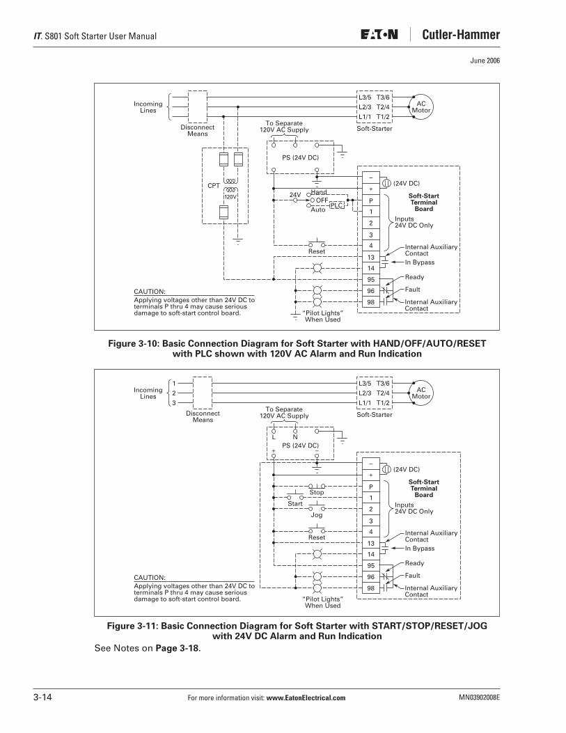
Figure 3-10: Basic Connection Diagram for Soft Starter with HAND/OFF/AUTO/RESET with PLC shown with 120V AC Alarm and Run Indication . . . . . . . . . . . . . . . . . . . . . . . . . . . . . . . . . . . . . . . . . . . . . . . . . . . . 3-14
Figure 3-11: Basic Connection Diagram for Soft Starter with START/STOP/RESET/JOG with 24V DC Alarm and Run Indication . . . . . . . . . . . . . . 3-14
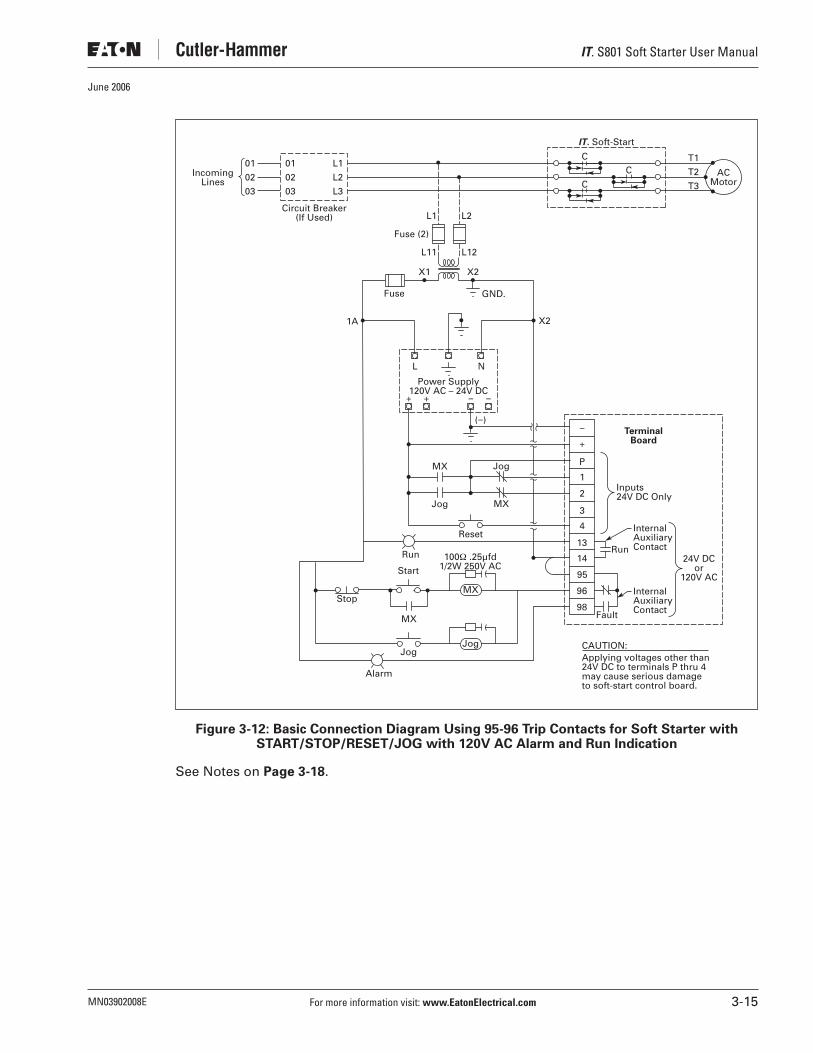
Figure 3-12: Basic Connection Diagram Using 95-96 Trip Contacts for Soft Starter with START/STOP/RESET/JOG with 120V AC Alarm and Run Indication . . . . . . . . . . . . . . . . . . . . . . . . . . . . . . . . . . . . . . . . . . . . . . . . . . . . 3-15
Figure 3-13: Basic Connection Diagram Using 95-96 Trip Contacts for Soft Starter with HAND/OFF/AUTO/RESET with 120V AC Alarm and Run Indication . . . . . . . . . . . . . . . . . . . . . . . . . . . . . . . . . . . . . . . . . . . . . . . . . . . . 3-16
Figure 3-14: Basic Connection Diagram Using 95-96 Trip Contacts for Soft Starter with START/STOP/RESET/JOG with 24V DC Alarm and Run Indication . . . . . . . . . . . . . . . . . . . . . . . . . . . . . . . . . . . . . . . . . . . . . . . . . . . . 3-17
Figure 3-15: 24V DC Control . . . . . . . . . . . . . . . . . . . . . . . . . . . . . . . . . . . . . . . . . . . . . . . . 3-21Figure 3-16: 120V AC Control . . . . . . . . . . . . . . . . . . . . . . . . . . . . . . . . . . . . . . . . . . . . . . . 3-22Figure 3-17: 24V DC Control with Edge Sensing . . . . . . . . . . . . . . . . . . . . . . . . . . . . . . . . 3-23Figure 5-1: Soft Starter SCRs . . . . . . . . . . . . . . . . . . . . . . . . . . . . . . . . . . . . . . . . . . . . . . . 5-1Figure 5-2: Selectable Kick-Start . . . . . . . . . . . . . . . . . . . . . . . . . . . . . . . . . . . . . . . . . . . . . 5-2Figure 5-3: Ramp Start . . . . . . . . . . . . . . . . . . . . . . . . . . . . . . . . . . . . . . . . . . . . . . . . . . . . . 5-3Figure 5-4: Current Limit Start . . . . . . . . . . . . . . . . . . . . . . . . . . . . . . . . . . . . . . . . . . . . . . 5-3Figure 5-5: Soft Stop . . . . . . . . . . . . . . . . . . . . . . . . . . . . . . . . . . . . . . . . . . . . . . . . . . . . . . 5-4Figure 6-1: Soft Start Control Interface Module (CIM) . . . . . . . . . . . . . . . . . . . . . . . . . . . 6-1Figure 6-2: Setting Trip Class and FLA on the CIM . . . . . . . . . . . . . . . . . . . . . . . . . . . . . . 6-2Figure 6-3: Programming the Kick Start Sequence . . . . . . . . . . . . . . . . . . . . . . . . . . . . . . 6-4Figure 6-4: Programming the Ramp Start Sequence . . . . . . . . . . . . . . . . . . . . . . . . . . . . 6-5Figure 6-5: Programming the Current Limit Start . . . . . . . . . . . . . . . . . . . . . . . . . . . . . . . 6-6Figure 6-6: Programming the Soft Stop . . . . . . . . . . . . . . . . . . . . . . . . . . . . . . . . . . . . . . . 6-7Figure 8-1: Troubleshooting Flowchart #1 . . . . . . . . . . . . . . . . . . . . . . . . . . . . . . . . . . . . . 8-2Figure 8-2: Troubleshooting Flowchart #2 . . . . . . . . . . . . . . . . . . . . . . . . . . . . . . . . . . . . . 8-3Figure A-1: Overload Trip Curves . . . . . . . . . . . . . . . . . . . . . . . . . . . . . . . . . . . . . . . . . . . . A-2Figure A-2: Setting Trip Class and FLA on the CIM . . . . . . . . . . . . . . . . . . . . . . . . . . . . . . A-3Figure A-3: Jam Detection . . . . . . . . . . . . . . . . . . . . . . . . . . . . . . . . . . . . . . . . . . . . . . . . . . A-4Figure A-4: Stall Detection . . . . . . . . . . . . . . . . . . . . . . . . . . . . . . . . . . . . . . . . . . . . . . . . . A-5Figure D-1:
IT.
Soft Starter CIM . . . . . . . . . . . . . . . . . . . . . . . . . . . . . . . . . . . . . . . . . . . . . . D-1Figure D-2: Pump Start Ramp and Soft Pump Stop . . . . . . . . . . . . . . . . . . . . . . . . . . . . . D-2

IT
. S801 Soft Starter User Manual
MN03902008E For more information visit:
www.EatonElectrical.com
v
June 2006
List of Tables
Table 3-1: Required Mounting Hardware . . . . . . . . . . . . . . . . . . . . . . . . . . . . . . . . . . . . . . . 3-7Table 3-2: Weight Support Requirements . . . . . . . . . . . . . . . . . . . . . . . . . . . . . . . . . . . . . . 3-7Table 3-3: Line and Load Power Wiring . . . . . . . . . . . . . . . . . . . . . . . . . . . . . . . . . . . . . . . . 3-9Table 3-4: 12-Pin Terminal Block Wiring Capacity . . . . . . . . . . . . . . . . . . . . . . . . . . . . . . . . 3-11Table 3-5: S801 Terminal Block Control Wiring . . . . . . . . . . . . . . . . . . . . . . . . . . . . . . . . . . 3-12Table 3-6: Cutler-Hammer Power Supplies . . . . . . . . . . . . . . . . . . . . . . . . . . . . . . . . . . . . . 3-18Table 4-1: Environmental Specifications . . . . . . . . . . . . . . . . . . . . . . . . . . . . . . . . . . . . . . . 4-1Table 4-2: Weight . . . . . . . . . . . . . . . . . . . . . . . . . . . . . . . . . . . . . . . . . . . . . . . . . . . . . . . . . . 4-1Table 4-3: Agency Standards and Certifications . . . . . . . . . . . . . . . . . . . . . . . . . . . . . . . . . 4-1Table 4-4: EMC Immunity . . . . . . . . . . . . . . . . . . . . . . . . . . . . . . . . . . . . . . . . . . . . . . . . . . . 4-2Table 4-5: Short Circuit Ratings. . . . . . . . . . . . . . . . . . . . . . . . . . . . . . . . . . . . . . . . . . . . . . . 4-3Table 6-1: Torque Setting and Percent Locked Rotor . . . . . . . . . . . . . . . . . . . . . . . . . . . . . 6-4Table 8-1: Troubleshooting — Status LED Off . . . . . . . . . . . . . . . . . . . . . . . . . . . . . . . . . . . 8-3Table 8-2: Troubleshooting — Status LED Green . . . . . . . . . . . . . . . . . . . . . . . . . . . . . . . . 8-3Table 8-3: Troubleshooting — Fault Shown on CIM . . . . . . . . . . . . . . . . . . . . . . . . . . . . . . 8-4Table 8-4: Troubleshooting — Soft Starter Fault Flash Codes Sent to CIM . . . . . . . . . . . 8-5Table 8-5: Troubleshooting — Fault Not Shown on CIM. . . . . . . . . . . . . . . . . . . . . . . . . . . 8-6Table 8-6: Troubleshooting — Excess Noise/Vibration in Motor . . . . . . . . . . . . . . . . . . . . 8-6Table 8-7: Troubleshooting — Audible Noise from Soft Starter —
Bypass Fails to Close/Chatters . . . . . . . . . . . . . . . . . . . . . . . . . . . . . . . . . . . . . . . . . . . . 8-6Table 8-8: Troubleshooting — Unit Will Not Stop . . . . . . . . . . . . . . . . . . . . . . . . . . . . . . . 8-7Table 8-9: Troubleshooting — Other Symptoms Not Listed . . . . . . . . . . . . . . . . . . . . . . . 8-7Table 9-1: Renewal Parts . . . . . . . . . . . . . . . . . . . . . . . . . . . . . . . . . . . . . . . . . . . . . . . . . . . . 9-1Table A-1: Overload — Adjustment Settings . . . . . . . . . . . . . . . . . . . . . . . . . . . . . . . . . . . . A-1Table A-2: Trip Reset . . . . . . . . . . . . . . . . . . . . . . . . . . . . . . . . . . . . . . . . . . . . . . . . . . . . . . . A-6Table A-3: Protection Settings. . . . . . . . . . . . . . . . . . . . . . . . . . . . . . . . . . . . . . . . . . . . . . . . A-6Table B-1: 15 Second Ramp, 4 Starts per Hour, 300% Current Limit @ 40°C . . . . . . . . . . B-1Table B-2: 25 Second Ramp, 4 Starts per Hour, 300% Current Limit @ 40°C . . . . . . . . . . B-2Table B-3: 15 Second Ramp, 4 Starts per Hour, 300% Current Limit @ 50°C . . . . . . . . . . B-3Table B-4: 50 Second Ramp, 2 Starts per Hour, 300% Current Limit @ 50°C . . . . . . . . . . B-4Table B-5: 15 Second Ramp, 4 Starts per Hour, 450% Current Limit @ 40°C . . . . . . . . . . B-5Table B-6: 30 Second Ramp, 4 Starts per Hour, 450% Current Limit @ 40°C . . . . . . . . . . B-6Table B-7: > 30 Second Ramp, > 4 Starts per Hour or >300% Current Limit . . . . . . . . . . . B-7Table B-8: Maximum Power Loss . . . . . . . . . . . . . . . . . . . . . . . . . . . . . . . . . . . . . . . . . . . . . B-8Table C-1: MOV Kit Options. . . . . . . . . . . . . . . . . . . . . . . . . . . . . . . . . . . . . . . . . . . . . . . . . . C-1

IT
. S801 Soft Starter User Manual
vi
For more information visit:
www.EatonElectrical.com
MN03902008E
June 2006
Safety
Eaton’s electrical business has made every effort to provide you with the safest motor starters on the market. However, we wish to point out how to safely operate and troubleshoot your starter.
The Meaning of Safety Statements
You will find various types of safety information on the following pages and on the labels attached to the equipment. This section explains their meaning.
The Safety Alert Symbol means ATTENTION! BECOME ALERT! YOUR SAFETY IS INVOLVED!
Le symbole d’alerte signifie ATTENTION ! SOYEZ VIGILANT ! VOTRE SECURITE EST EN JEU !
El símbolo de alerta de seguridad significa ¡ATENCIÓN! ¡ESTÉ ALERTA! ¡SU SEGURIDAD ESTÁ EN JUEGO!
Danger means that failure to follow the safety statement
will
result in serious personal injury, death, or substantial property damage.
Danger signifie que l’inobservation de l’énoncé de sécurité
entraînera
des blessures corporelles graves, la mort ou des dégâts matériels substantiels.
Peligro significa que si no se respeta la indicación de seguridad, se
producirán
lesiones personales graves, la muerte o daño considerable a la propiedad.
Warning means that failure to follow the safety statement
could
result in serious personal injury, death, or substantial property damage.
Avertissement signifie que l’inobservation de l’énoncé de sécurité
pourrait
entraîner des blessures corporelles graves, la mort ou des dégâts matériels substantiels.
Advertencia significa que si no se respeta la indicación de seguridad se
pueden
producir lesiones personales graves, la muerte o daños considerables a la propiedad.
Caution means that failure to follow the safety statement
may
result in minor or moderate personal injury or property damage.
Attention signifie que l’inobservation de l’énoncé de sécurité
peut
entraîner des blessures corporelles mineures ou modérés ou des dégâts matériels.
Precaución significa que si no se respeta la indicación de seguridad, se
pueden
producir lesiones personales menores o moderadas, o daños a la propiedad.
Notice means that failure to follow these instructions
could
cause damage to the equipment or cause it to operate improperly.
Avis signifie que l’inobservation de ses instructions
pourrait
entraîner des dégâts à ou le mauvais fonctionnement de l’équipement.
Aviso significa que si no se siguen estas instrucciones, se
pueden
producir daños al equipo o provocar que funcione de manera incorrecta.
!
!
!Danger Danger Peligro
Warning Avertissement Advertencia
Caution! Attention! Precaución!
Notice Avis Aviso
IT
. S801 Soft Starter User Manual
MN03902008E For more information visit:
www.EatonElectrical.com
vii
June 2006
IT
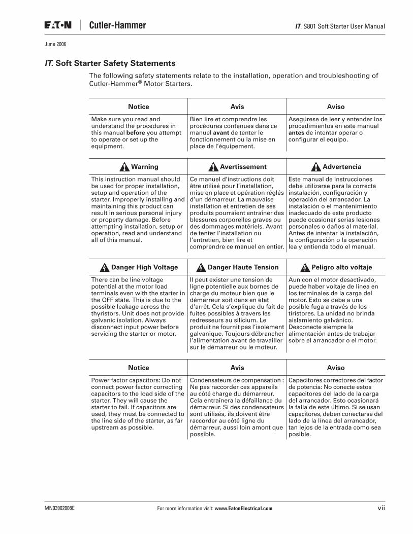
. Soft Starter Safety Statements
The following safety statements relate to the installation, operation and troubleshooting of Cutler-Hammer
®
Motor Starters.
Make sure you read and understand the procedures in this manual
before
you attempt to operate or set up the equipment.
Bien lire et comprendre les procédures contenues dans ce manuel
avant
de tenter le fonctionnement ou la mise en place de l’équipement.
Asegúrese de leer y entender los procedimientos en este manual
antes
de intentar operar o configurar el equipo.
This instruction manual should be used for proper installation, setup and operation of the starter. Improperly installing and maintaining this product can result in serious personal injury or property damage. Before attempting installation, setup or operation, read and understand all of this manual.
Ce manuel d’instructions doit être utilisé pour l’installation, mise en place et opération réglés d’un démarreur. La mauvaise installation et entretien de ses produits pourraient entraîner des blessures corporelles graves ou des dommages matériels. Avant de tenter l’installation ou l’entretien, bien lire et comprendre ce manuel en entier.
Este manual de instrucciones debe utilizarse para la correcta instalación, configuración y operación del arrancador. La instalación o el mantenimiento inadecuado de este producto puede ocasionar serias lesiones personales o daños al material. Antes de intentar la instalación, la configuración o la operación lea y entienda todo el manual.
There can be line voltage potential at the motor load terminals even with the starter in the OFF state. This is due to the possible leakage across the thyristors. Unit does not provide galvanic isolation. Always disconnect input power before servicing the starter or motor.
Il peut exister une tension de ligne potentielle aux bornes de charge du moteur bien que le démarreur soit dans en état d’arrêt. Cela s’explique du fait de fuites possibles à travers les redresseurs au silicium. Le produit ne fournit pas l’isolement galvanique. Toujours débrancher l’alimentation avant de travailler sur le démarreur ou le moteur.
Aun con el motor desactivado, puede haber voltaje de línea en los terminales de la carga del motor. Esto se debe a una posible fuga a través de los tiristores. La unidad no brinda aislamiento galvánico. Desconecte siempre la alimentación antes de trabajar sobre el arrancador o el motor.
Power factor capacitors: Do not connect power factor correcting capacitors to the load side of the starter. They will cause the starter to fail. If capacitors are used, they must be connected to the line side of the starter, as far upstream as possible.
Condensateurs de compensation : Ne pas raccorder ces appareils au côté charge du démarreur. Cela entraînera la défaillance du démarreur. Si des condensateurs sont utilisés, ils doivent être raccorder au côté ligne du démarreur, aussi loin amont que possible.
Capacitores correctores del factor de potencia: No conecte estos capacitores del lado de la carga del arrancador. Esto ocasionará la falla de este último. Si se usan capacitores, deben conectarse del lado de la línea del arrancador, tan lejos de la entrada como sea posible.
Notice Avis Aviso
Warning Avertissement Advertencia
Danger High Voltage Danger Haute Tension Peligro alto voltaje
Notice Avis Aviso

IT
. S801 Soft Starter User Manual
viii
For more information visit:
www.EatonElectrical.com
MN03902008E
June 2006
Dangers, Warnings, Cautions and Notes
Dangers
Hazardous voltage can cause electric shock and burns. To avoid shock hazard, disconnect all power to the controller, motor or other control devices before any work is performed on this equipment. Failure to do so will result in personal injury, death or substantial property damage.
Une tension électrique dangereuse peut causer des chocs électriques et des brûlures. Pour éviter des chocs électriques, débrancher l’alimentation du contrôleur, du moteur ou des autres appareils de contrôle avant d’y effectuer du travail. L’inobservation de ces instructions entraînera des blessures corporelles graves, la mort ou des dégâts matériels substantiels.
Voltajes peligrosos que pueden causar descargas eléctricas y quemaduras. Para evitar descargas eléctricas, desconecte la alimentación del controlador, del motor u otros dispositivos de control antes de efectuar cualquier trabajo en el equipo. El incumplimiento de estas medidas ocasionará lesiones personales, la muerte o daños importantes al material.
Do not apply a disconnect device on the output of the
IT.
Soft Starter unless a means to turn off the soft starter when disconnect switch is open is utilized. Opening disconnect while the
IT.
Soft Starter is operating may cause a malfunction. Closing disconnect switch while the
IT.
Soft Starter is operating will result in a soft starter failure and potential equipment damage and personnel hazard.
Ne pas appliquer un appareil de sectionnement sur la sortie du démarreur progressif
IT.
à moins qu’un moyen d’éteindre le démarreur progressif quand l’interrupteur de sectionnement est ouvert soit utilisé. Le fait d’ouvrir l’interrupteur de sectionnement pendant le fonctionnement du démarreur progressif
IT.
peut entraîner une défaillance. Le fait d’éteindre l’interrupteur de sectionnement pendant le fonctionnement du démarreur progressif
IT.
entraînera la défaillance du démarreur progressif et des dégâts à l’équipement ou risque au personnel.
No aplique un dispositivo de desconexión a la salida del arrancador
IT
. Soft Starter a menos que se utilice un medio para apagar el arrancador cuando el interruptor de desconexión está abierto. La apertura del interruptor de desconexión mientras el arrancador
IT
. está operando puede ocasionar un funcionamiento incorrecto. El cierre del interruptor de desconexión mientras el arrancador
IT
. está operando producirá una falla de dicho arrancador, como también potenciales daños a los equipos y riesgo para el personal.
Danger High Voltage Danger Haute Tension Peligro alto voltaje

IT
. S801 Soft Starter User Manual
MN03902008E For more information visit:
www.EatonElectrical.com
ix
June 2006
Dangers, continued
Warnings
Hazardous voltage can cause electric shock and burns. Always disconnect power before proceeding with any work on this product.
Une tension électrique dangereuse peut causer des chocs électriques et des brûlures. Il faut toujours débrancher l’alimentation électrique avant de travailler sur ce produit.
Voltajes peligrosos que pueden causar descargas eléctricas y quemaduras. Siempre desconecte la energía eléctrica antes de efectuar cualquier trabajo en el equipo.
Do not work on energized equipment unless absolutely required. If troubleshooting procedure requires equipment to be energized, all work must be performed by properly qualified personnel, following appropriate safety practices and precautionary measures.
Ne pas travailler sur d’équipement sous tension sauf si c’est absolument nécessaire. Si des méthodes de dépannage exigent que l’équipement soit sous tension, tout travail doit être faire par du personnel qualifié, suivant des pratiques de sécurité et des mesures de précaution appropriées.
No trabaje en equipos en funcionamiento, a menos que sea absolutamente necesario. Si un procedimiento de solución de problemas requiere que el equipo permanezca encendido, todo el trabajo lo debe realizar personal adecuadamente calificado, respetando las prácticas de seguridad y las medidas preventivas correspondientes.
Danger High Voltage Danger Haute Tension Peligro alto voltaje
Danger High Voltage Danger Haute Tension Peligro alto voltaje
After mounting the unit, remove and discard the lifting eye and packaging bolts before continuing with the installation process.
Après que l’appareil sera supporté, enlever et jeter les œillets de levage et les boulons de l’emballage avant de poursuivre l’installation.
Después de montar la unidad, retire y elimine la argolla de izada y los pernos de embalaje antes de continuar con el proceso de instalación.
Make sure you read and understand all of the safety statements in the safety section of this manual before you begin troubleshooting.
S’assurer de bien lire et comprendre les énoncés de sécurité dans le passage de sécurité de ce manuel avant de commencer le dépannage.
Antes de comenzar a solucionar problemas, asegúrese de leer y comprender todas las indicaciones de seguridad que aparecen en la sección de seguridad de este manual.
Warning Avertissement Advertencia
Warning Avertissement Advertencia
IT
. S801 Soft Starter User Manual
x
For more information visit:
www.EatonElectrical.com
MN03902008E
June 2006
Cautions
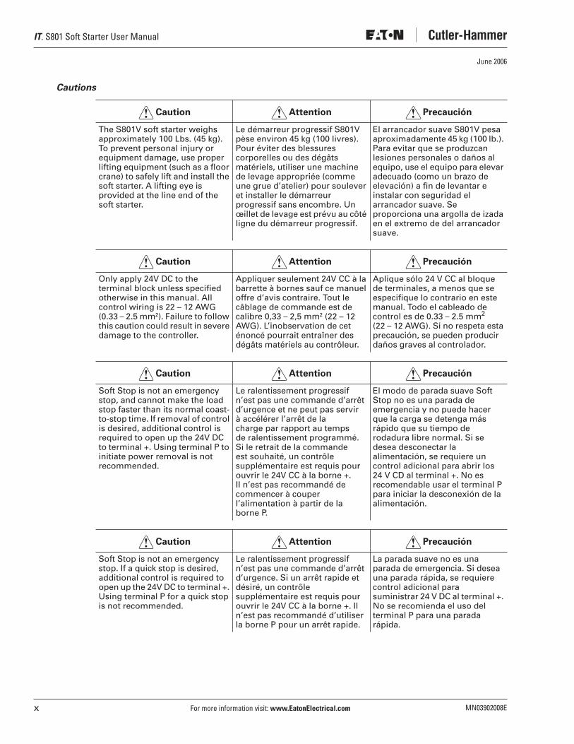
The S801V soft starter weighs approximately 100 Lbs. (45 kg). To prevent personal injury or equipment damage, use proper lifting equipment (such as a floor crane) to safely lift and install the soft starter. A lifting eye is provided at the line end of the soft starter.
Le démarreur progressif S801V pèse environ 45 kg (100 livres). Pour éviter des blessures corporelles ou des dégâts matériels, utiliser une machine de levage appropriée (comme une grue d’atelier) pour soulever et installer le démarreur progressif sans encombre. Un œillet de levage est prévu au côté ligne du démarreur progressif.
El arrancador suave S801V pesa aproximadamente 45 kg (100 lb.). Para evitar que se produzcan lesiones personales o daños al equipo, use el equipo para elevar adecuado (como un brazo de elevación) a fin de levantar e instalar con seguridad el arrancador suave. Se proporciona una argolla de izada en el extremo de del arrancador suave.
Only apply 24V DC to the terminal block unless specified otherwise in this manual. All control wiring is 22 – 12 AWG (0.33 – 2.5 mm
2
). Failure to follow this caution could result in severe damage to the controller.
Appliquer seulement 24V CC à la barrette à bornes sauf ce manuel offre d’avis contraire. Tout le câblage de commande est de calibre 0,33 – 2,5 mm
2
(22 – 12 AWG). L’inobservation de cet énoncé pourrait entraîner des dégâts matériels au contrôleur.
Aplique sólo 24 V CC al bloque de terminales, a menos que se especifique lo contrario en este manual. Todo el cableado de control es de 0.33 – 2.5 mm
2
(22 – 12 AWG). Si no respeta esta precaución, se pueden producir daños graves al controlador.
Soft Stop is not an emergency stop, and cannot make the load stop faster than its normal coast-to-stop time. If removal of control is desired, additional control is required to open up the 24V DC to terminal +. Using terminal P to initiate power removal is not recommended.
Le ralentissement progressif n’est pas une commande d’arrêt d’urgence et ne peut pas servir à accélérer l’arrêt de la charge par rapport au temps de ralentissement programmé. Si le retrait de la commande est souhaité, un contrôle supplémentaire est requis pour ouvrir le 24V CC à la borne +. Il n’est pas recommandé de commencer à couper l’alimentation à partir de la borne P.
El modo de parada suave Soft Stop no es una parada de emergencia y no puede hacer que la carga se detenga más rápido que su tiempo de rodadura libre normal. Si se desea desconectar la alimentación, se requiere un control adicional para abrir los 24 V CD al terminal +. No es recomendable usar el terminal P para iniciar la desconexión de la alimentación.
Soft Stop is not an emergency stop. If a quick stop is desired, additional control is required to open up the 24V DC to terminal +. Using terminal P for a quick stop is not recommended.
Le ralentissement progressif n’est pas une commande d’arrêt d’urgence. Si un arrêt rapide et désiré, un contrôle supplémentaire est requis pour ouvrir le 24V CC à la borne +. Il n’est pas recommandé d’utiliser la borne P pour un arrêt rapide.
La parada suave no es una parada de emergencia. Si desea una parada rápida, se requiere control adicional para suministrar 24 V DC al terminal +. No se recomienda el uso del terminal P para una parada rápida.
Caution! Attention! Precaución!
Caution! Attention! Precaución!
Caution! Attention! Precaución!
Caution! Attention! Precaución!

IT. S801 Soft Starter User Manual
MN03902008E For more information visit: www.EatonElectrical.com xi
June 2006
Cautions, continued
Notes
Soft Stop does not provide any braking. It cannot cause the motor and its load to stop faster than their normal unpowered coast down time.
Le ralentissement progressif n’assure aucun freinage. Il ne peut pas servir à accélérer l’arrêt du moteur et sa charge par rapport au temps de ralentissement programmé.
La parada suave no proporciona ningún tipo de freno. No puede hacer que el motor y su carga se detengan con mayor rapidez que su tiempo normal de funcionamiento por inercia.
Never megger a motor while it is connected to the IT. Soft Starter. Disconnect the leads at the IT. Soft Starter before meggering the motor.
Ne jamais régler un moteur alors qu’il est branché au démarreur progressif IT. Débrancher les fils au démarreur progressif IT. Avant de régler le moteur.
Nunca efectúe pruebas del motor con un megóhmetro mientras esté conectado al arrancador Soft Starter IT. Desconecte los cables en el arrancador IT. antes de usar el megóhmetro.
Caution! Attention! Precaución!
Caution! Attention! Precaución!
The S801V Soft Starter includes mounting hardware (8 1/4-20 x 1.5 Allen hex head cap screws and special washers). Do not substitute for this hardware. See Figure 3-6 on Page 3-6 for panel hole locations. Applicable codes or standards must be considered before locating and mounting the soft starter. The four special rectangular/rounded washers must be used on the two innermost mounting holes on both the line and load side of the soft starter.
Le démarreur progressif S801V inclut des matériels de support (vis à tête hexagonale 8-1/4-20 x 1,5 et des rondelles spéciales). Ne substituer pas pour ces matériels. Consulter la Figure 3-6 de la Page 3-6 pour les locations des trous dans le panneau. Tenir compte des normes et des codes existants avant de localiser et de monter le démarreur progressif. Les quatre rondelles rectangulaires/circulaires spéciales doivent être utiliser aux deux trous de support les plus intérieurs sur le côté ligne et le côté charge du démarreur progressif.
El arrancador suave S801V incluye piezas metálicas de montaje (tornillos Allen de cabeza hexagonal de 8 1/4-20 x 1.5 y arandelas especiales). No las sustituya. Consulte la Figura 3-6 que aparece en la página 3-6 para conocer las ubicaciones de los orificios del panel. Antes de ubicar y montar el arrancador suave, se deben considerar los códigos o las normas pertinentes. Las cuatro arandelas rectangulares/redondas especiales se deben usar en los dos orificios de montaje que se encuentren más al interior, en los lados de línea y de carga del arrancador suave.
Notice Avis Aviso

IT. S801 Soft Starter User Manual
xii For more information visit: www.EatonElectrical.com MN03902008E
June 2006
IT. S801 Soft Starter User Manual
MN03902008E For more information visit: www.EatonElectrical.com 1-1
June 2006
Chapter 1 — Overview
General Introduction
The Cutler-Hammer® Intelligent Technologies S801 IT. Soft Starter from Eaton’s electrical business is an electronic, self-contained, panel- or enclosure-mounted motor soft-starting device. It is intended to provide three-phase induction motors with a smooth start, both mechanically and electrically. The S801 Soft Starters utilize six thyristors connected in a full wave power bridge. Varying the thyristor conduction period controls the voltage applied to the motor. This in turn controls the torque developed by the motor. After the motor reaches speed, contacts are closed to bypass the thyristors.
The S801 is designed to fulfill the industrial service requirements for applications such as Chillers, Pumps and Machine Tools that require less than 85% of the motor’s rated starting torque for worst case starting condition.
The S801 meets all relevant specifications set forth by NEMA ICS 1, ICS 2 and ICS 5, UL 508, IEC 60947-4-2, CE and CSA.
This user manual covers everything you need to know in order to install, set up, operate, troubleshoot and maintain the S801.
However, no publication can take into account every possible situation. If you require further assistance with any aspect of this product, or a particular application, please contact us.
For contact information, please see Chapter 9.
IT. S801 Soft Starter User Manual
1-2 For more information visit: www.EatonElectrical.com MN03902008E
June 2006
General Appearance Notes
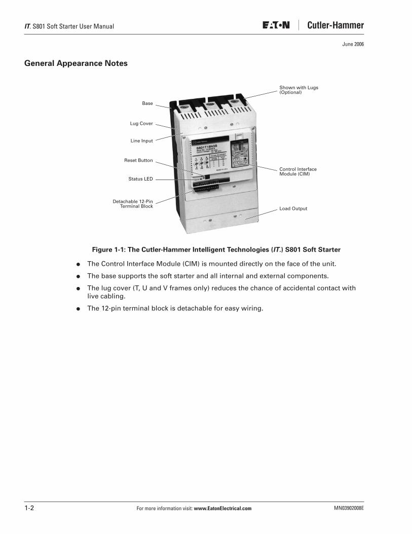
Figure 1-1: The Cutler-Hammer Intelligent Technologies (IT.) S801 Soft Starter
● The Control Interface Module (CIM) is mounted directly on the face of the unit.
● The base supports the soft starter and all internal and external components.
● The lug cover (T, U and V frames only) reduces the chance of accidental contact with live cabling.
● The 12-pin terminal block is detachable for easy wiring.
Detachable 12-PinTerminal Block
Base
Load Output
Control Interface Module (CIM)
Shown with Lugs(Optional)
Status LED
Lug Cover
Line Input
Reset Button

IT. S801 Soft Starter User Manual
MN03902008E For more information visit: www.EatonElectrical.com 2-1
June 2006
Chapter 2 — Receipt/Unpacking
General
Upon receipt of the unit, verify that the catalog number and unit options stated on the shipping container match those stated on the order/purchase form.
Inspect the equipment upon delivery. Report any crate or carton damage to the carrier prior to accepting the delivery. Have this information noted on the freight bill. Eaton is not responsible for damage incurred in shipping.
Unpacking
Remove all packing material from the unit. Be sure to remove all packing material from lug locations. Also, make sure no packing material blocks the airflow near the fans. For V frame units, verify mounting hardware has been included with shipment.
Check the unit for any signs of shipping damage. If damage is found after unpacking, report it to the freight company. Retain the packaging materials for carrier to review.
Verify that the unit’s catalog number and options match those stated on the order/purchase form.
Storage
It is recommended that the unit be stored in its original shipping box/crate until it is to be installed.
The unit should be stored in a location where:
● The ambient temperature is -58°F – 158°F (-50°C – 70°C)
● The relative humidity is 0% – 95%, non-condensing
● The environment is dry, clean and non-corrosive
● The unit will not be subjected to high shock or vibration conditions

IT. S801 Soft Starter User Manual
2-2 For more information visit: www.EatonElectrical.com MN03902008E
June 2006

IT. S801 Soft Starter User Manual
MN03902008E For more information visit: www.EatonElectrical.com 3-1
June 2006
Chapter 3 — Installation
Mounting
Models S801N, S801R, S801T, S801U and S801V
The S801 is easy to mount. It does not require any special tools.
To aid you with panel layout, refer to the dimension drawings in Figures 3-2 through 3-6 of this manual. Drill and tap holes per mounting hole location as shown.
To mount the unit, use all the hardware specified in Table 3-1 on Page 3-7. Tighten to the torque specified.
The T, U and V frame S801 is supplied with a lifting eye mounted on the center phase of the line end of the device. This will aid in mounting the unit.
Model S801V
After mounting the unit, remove and discard the lifting eye and packaging bolts before continuing with the installation process.
Après que l’appareil sera supporté, enlever et jeter les œillets de levage et les boulons de l’emballage avant de poursuivre l’installation.
Después de montar la unidad, retire y elimine la argolla de izada y los pernos de embalaje antes de continuar con el proceso de instalación.
Warning Avertissement Advertencia
The S801V soft starter weighs approximately 100 Lbs. (45 kg). To prevent personal injury or equipment damage, use proper lifting equipment (such as a floor crane) to safely lift and install the soft starter. A lifting eye is provided at the line end of the soft starter.
Le démarreur progressif S801V pèse environ 45kg (100 livres). Pour éviter des blessures corporelles ou des dégâts matériels, utiliser une machine de levage appropriée (comme une grue d’atelier) pour soulever et installer le démarreur progressif sans encombre. Un œillet de levage est prévu au côté ligne du démarreur progressif.
El arrancador suave S801V pesa aproximadamente 45 kg (100 lb.). Para evitar que se produzcan lesiones personales o daños al equipo, use el equipo para elevar adecuado (como un brazo de elevación) a fin de levantar e instalar con seguridad el arrancador suave. Se proporciona una argolla de izada en el extremo de del arrancador suave.
Caution! Attention! Precaución!

IT. S801 Soft Starter User Manual
3-2 For more information visit: www.EatonElectrical.com MN03902008E
June 2006
Drill and tap the eight mounting holes. Thread the two lower middle screws (with special flat washer and lockwasher) into the panel before lifting the soft starter. These two screws will assist in mounting. Special mounting hardware is included with the soft starter. Hardware supplied must be used.
Hook lifting equipment to the soft starter lifting eye. If you are using a crane, minimize the chain length between the boom and the soft starter. Make sure that the back of the soft starter is oriented to the panel-mounting surface. Make sure that the lifting equipment hook is fully engaged with the soft starter lifting eye before lifting.
Slowly lift the soft starter to about 2 in. (5 cm) above the mounting location. Then move it back against the mounting panel. Carefully lower the soft starter onto the two mounting screws. Make sure the screws align with the slots on the load end of the soft starter, and that the two washers are between the soft starter base and the screw head.
Install and tighten the remaining six mounting screws, washers and lockwashers. Then tighten the two lower middle screws. Tighten all eight screws to 50 Lb-in (5.6 N•m). Disengage and remove the lifting equipment.
The S801V soft starter includes mounting hardware (8 1/4-20 x 1.5 Allen hex head cap screws and special washers). Do not substitute for this hardware. See Figure 3-6 on Page 3-6 for panel hole locations. Applicable codes or standards must be considered before locating and mounting the soft starter. The four special rectangular/rounded washers must be used on the two innermost mounting holes on both the line and load side of the soft starter.
Le démarreur progressif S801V inclut des matériels de support (vis à tête hexagonale 8-1/4-20 x 1,5 et des rondelles spéciales). Ne substituer pas pour ces matériels. Consulter la Figure 3-6 de la Page 3-6 pour les locations des trous dans le panneau. Tenir compte des normes et des codes existants avant de localiser et de monter le démarreur progressif. Les quatre rondelles rectangulaires/circulaires spéciales doivent être utiliser aux deux trous de support les plus intérieurs sur le côté ligne et le côté charge du démarreur progressif.
El arrancador suave S801V incluye piezas metálicas de montaje (tornillos Allen de cabeza hexagonal de 8 1/4-20 x 1.5 y arandelas especiales). No las sustituya. Consulte la Figura 3-6 que aparece en la página 3-6 para conocer las ubicaciones de los orificios del panel. Antes de ubicar y montar el arrancador suave, se deben considerar los códigos o las normas pertinentes. Las cuatro arandelas rectangulares/redondas especiales se deben usar en los dos orificios de montaje que se encuentren más al interior, en los lados de línea y de carga del arrancador suave.
After mounting the unit, remove and discard the lifting eye and packaging bolts before continuing with the installation process.
Après que l’appareil sera supporté, enlever et jeter les œillets de levage et les boulons de l’emballage avant de poursuivre l’installation.
Después de montar la unidad, retire y elimine la argolla de izada y los pernos de embalaje antes de continuar con el proceso de instalación.
Notice Avis Aviso
Warning Avertissement Advertencia
IT. S801 Soft Starter User Manual
MN03902008E For more information visit: www.EatonElectrical.com 3-3
June 2006
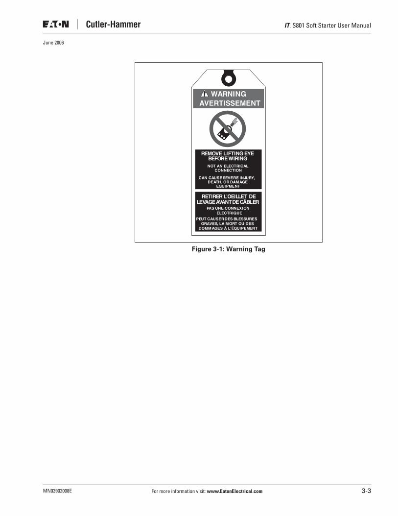
Figure 3-1: Warning Tag
REMOVE LIFTING EYEBEFOREWIRINGNOT AN ELECTRICAL
CONNECTION
CAN CAUSE SEVERE INJURY,DEATH, OR DAMAGE
EQUIPMENT
PAS UNE CONNEXIONE
E
LECTRIQUE
PEUT CAUSERDES BLESSURESGRAVES, LA MORT OU DES
DOMMAGES Á L’ QUIPEMENT
RETIRER L’OEILLET DELEVAGEAVANTDECÂBLER
WARNINGAVERTISSEMENT
IT. S801 Soft Starter User Manual
3-4 For more information visit: www.EatonElectrical.com MN03902008E
June 2006
Dimensions
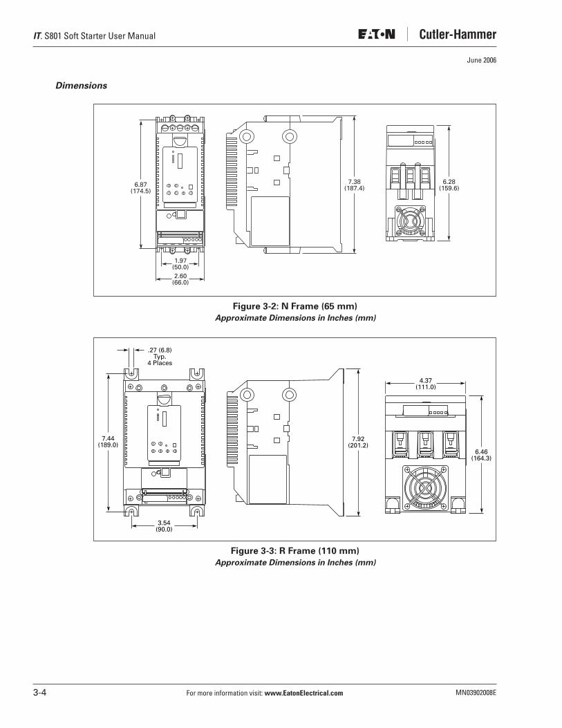
Figure 3-2: N Frame (65 mm)
Approximate Dimensions in Inches (mm)
Figure 3-3: R Frame (110 mm)
Approximate Dimensions in Inches (mm)
6.87(174.5)
1.97(50.0)2.60
(66.0)
7.38(187.4)
6.28(159.6)
3.54(90.0)
7.44(189.0)
4.37(111.0)
7.92(201.2)
6.46(164.3)
.27 (6.8)Typ.
4 Places

IT. S801 Soft Starter User Manual
MN03902008E For more information visit: www.EatonElectrical.com 3-5
June 2006
Figure 3-4: T Frame (200 mm)Approximate Dimensions in Inches (mm)
Figure 3-5: U Frame (200 mm)Approximate Dimensions in Inches (mm)
6.22(158.0)
7.65(194.4)
11.77(299.0)Slots
12.71(322.9)
2.95(75.0)Slots
.28(7.1)
Slots Typ.6 Places
5.91 (150.0)Slots
11.77 (299.0)Mounting
5.20 (132.0)Mounting
Mounting Slotsfor M6 (1/4) Screws(Up to 6 Quantity)
.47(11.9)
7.08(179.9)
12.72(323.1)
7.73(196.3)
5.20 (132.0)Pole Centers
C L
C L
IT. S801 Soft Starter User Manual
3-6 For more information visit: www.EatonElectrical.com MN03902008E
June 2006
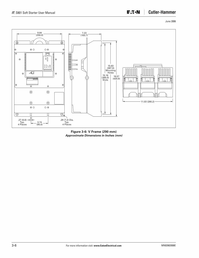
Figure 3-6: V Frame (290 mm)Approximate Dimensions in Inches (mm)
3.74(95.0)
.28 (7.2) Dia.Typ.
4 Places
15.16(385.0)Slots
15.63(397.0)
MountingHoles
16.57(420.8)
7.23(183.7)
9.84(250.0)
11.03 (280.2)
.27 (6.8)Typ.
4 Places

IT. S801 Soft Starter User Manual
MN03902008E For more information visit: www.EatonElectrical.com 3-7
June 2006
Required Mounting Hardware
Table 3-1: Required Mounting Hardware
Weight Support Requirements
Table 3-2: Weight Support Requirements
FrameSize Screw Size Washer Size
Quantity Required
Torque Required
N #10 – 32 x 0.5 Standard #10 Lockwasher and Flat Washer
4 15 Lb-in(1.7 N•m)
R 1/4 – 20 x 0.625 Standard 1/4 Lockwasher and Flat Washer
4 25 Lb-in (2.8 N•m)
T and U 1/4 – 20 x 0.625 Standard 1/4 Lockwasher and Flat Washer
6 30 Lb-in (3.4 N•m)
V 1/4 – 20 x 1.5 Grade 8 Allen head hex cap screws
Quantity: 4 ID: 0.270 OD: 0.495 – 0.505Max. 0.055 Thick
8 50 Lb-in (5.6 N•m)
Quantity: 4 Special Washer
Included with V Frame Units
FrameSize Weight of Unit
N 5.8 Lbs. (2.6 Kg)
R 10.5 Lbs. (4.8 Kg)
T and U 48 Lbs. (21.8 Kg) with lugs
41 Lbs. (18.6 Kg) without lugs
V 103 Lbs. (46.8 Kg) with lugs
91 Lbs. (41.4 Kg) without lugs

IT. S801 Soft Starter User Manual
3-8 For more information visit: www.EatonElectrical.com MN03902008E
June 2006
Power Wiring
Using the wiring diagrams in Figures 3-9 through 3-14 and Table 3-3 below as guides, connect the line, Motor, and Power Supply wiring in accordance with appropriate local and national codes.
Note: To provide optimum motor protection the Line and Motor power wiring should be tightly bundled and run perpendicular to the orientation of the S801.
Safety Notices
Note: Short circuit protection must be applied on the line side of the soft starter.
The S801 is to be wired into the three-phase line feeding the three main motor input leads as would be done for normal across-the-line starting. It must not be wired internally between
motor windings. Refer to the motor nameplate for correct wiring information for normal across-the-line operation. Contact Eaton if a special motor wiring requirement exists before wiring your starter.
By factory default, the S801 is to be connected with an ABC phase rotation on the incoming power wiring. If the motor turns in the incorrect direction upon energization, exchange two phases at the motor terminal box or at the output terminals of the soft starter. Changing the input wiring will cause a voltage phase reversal trip.
Hazardous voltage can cause electric shock and burns. To avoid shock hazard, disconnect all power to the controller, motor or other control devices before any work is performed on this equipment. Failure to do so will result in personal injury, death or substantial property damage.
Une tension électrique dangereuse peut causer des chocs électriques et des brûlures. Pour éviter des chocs électriques, débrancher l’alimentation du contrôleur, du moteur ou des autres appareils de contrôle avant d’y effectuer du travail. L’inobservation de ces instructions entraînera des blessures corporelles graves, la mort ou des dégâts matériels substantiels.
Voltajes peligrosos que pueden causar descargas eléctricas y quemaduras. Para evitar descargas eléctricas, desconecte la alimentación del controlador, del motor u otros dispositivos de control antes de efectuar cualquier trabajo en el equipo. El incumplimiento de estas medidas ocasionará lesiones personales, la muerte o daños importantes al material.
Do not apply a disconnect device on the output of the IT. Soft Starter unless a means to turn off the soft starter when disconnect switch is open is utilized. Opening disconnect while the IT. Soft Starter is operating may cause a malfunction. Closing disconnect switch while the IT. Soft Starter is operating will result in a soft starter failure and potential equipment damage and personnel hazard.
Ne pas appliquer un appareil de sectionnement sur la sortie du démarreur progressif IT. à moins qu’un moyen d’éteindre le démarreur progressif quand l’interrupteur de sectionnement est ouvert soit utilisé. Le fait d’ouvrir l’interrupteur de sectionnement pendant le fonctionnement du démarreur progressif IT. peut entraîner une défaillance. Le fait d’éteindre l’interrupteur de sectionnement pendant le fonctionnement du démarreur progressif IT. entraînera la défaillance du démarreur progressif et des dégâts à l’équipement ou risque au personnel.
No aplique un dispositivo de desconexión a la salida del arrancador IT. Soft Starter a menos que se utilice un medio para apagar el arrancador cuando el interruptor de desconexión está abierto. La apertura del interruptor de desconexión mientras el arrancador IT. está operando puede ocasionar un funcionamiento incorrecto. El cierre del interruptor de desconexión mientras el arrancador IT. está operando producirá una falla de dicho arrancador, como también potenciales daños a los equipos y riesgo para el personal.
Danger High Voltage Danger Haute Tension Peligro alto voltaje

IT. S801 Soft Starter User Manual
MN03902008E For more information visit: www.EatonElectrical.com 3-9
June 2006
If the input phase sequence to the S801 must be ACB, the incoming phase sequence will need to be changed to ACB. Setting ACB as the incoming phase sequence causes the ABC incoming phase sequence to cause a voltage phase reversal trip.
IMPORTANT: The reversing contactor must never be switched while the soft starter is operating. In order to gain the full benefit of the S801 with a reversing contactor, the S801 needs to be OFF when switching the direction. The soft starter settings must account for catching a motor spinning in the opposite direction upon soft restarts. The time required for slowing the motor to a stop and then ramping up to speed in the opposite direction adds to the overall starting time. This will also impact the overload protection setting.
See “Motor/Application Considerations” section in Appendix C of this manual for information on typical motor winding configurations.
Line and Load power wiring data is shown in Table 3-3.
Table 3-3: Line and Load Power Wiring
� Requires special lug cover. Check with Eaton for availability. � CSA approved 350 MCM – 500 MCM
Frame Size Lug Kit Options
Number of Conductors Lug Type
Wire SizesCu 75°COnly
TorqueRequirements
Number of Kits Required
N Supplied Standard with Box Lugs
1 Box Lug 2 AWG 50 Lb-in (5.6 N•m) N/A
4 – 6 AWG 45 Lb-in (5.0 N•m)
8 AWG 40 Lb-in (4.5 N•m)
10 – 14 AWG 35 Lb-in (4.0 N•m)
R Supplied Standard with Box Lugs
1 Box Lug 14 – 8 AWG(2.5 – 10 mm2)
90 – 100 Lb-in(10.1 – 11.3 N•m)
N/A
6 – 4 AWG(16 – 25 mm2)
3 – 3/0 AWG(27 – 95 mm2)
T and U EML22 2 — 4 – 1/0 MCM(21.2 – 53.5 mm2)
250 Lb-in (28.3 N•m) 2
EML23 1 — 4/0 – 500 MCM(107 – 240 mm2)
250 Lb-in (28.3 N•m)
EML24 2 � — 4/0 – 500 MCM(107 – 240 mm2)
250 Lb-in (28.3 N•m)
EML25 1 — 2/0 – 300 MCM(70 – 150 mm2)
225 Lb-in (25.5 N•m)
EML26 2 — 2/0 – 300 MCM(70 – 150 mm2)
225 Lb-in (25.5 N•m)
V EML28 2 � — 4/0 – 500 MCM(107 – 240 mm2)
250 Lb-in (28.3 N•m) 2
EML30 4 � — 4/0 – 500 MCM(107 – 240 mm2)
250 Lb-in (28.3 N•m)
EML32 6 �� — 4/0 – 500 MCM(107 – 240 mm2)
250 Lb-in (28.3 N•m)
EML33 4 — 2/0 – 300 MCM(70 – 150 mm2)
225 Lb-in (25.5 N•m)

IT. S801 Soft Starter User Manual
3-10 For more information visit: www.EatonElectrical.com MN03902008E
June 2006
Lugs for T, U and V Frame
T, U and V frame units are supplied standard without lugs. If lugs are needed, they can be ordered through your local Eaton distributor. Each lug kit contains three lugs, mounting hardware, and instructions for use on either line or load side of the IT. Soft Starter. Catalog numbers and wire ranges for lug kits are listed in the table above.
Lug Installation
Note: For additional motor and system protection, a Metal Oxide Varistor (MOV) may be installed on the line side of the unit. An MOV can also be installed on the load side of the Soft Starter if additional protection is desired. Generally, it is more common to use a MOV on the line side. Refer to the instructions provided with the MOV kit.
1. For T, U and V Frame Soft Starters, remove line and load terminal covers by removing the screws that hold each cover (and the MOV, if installed) onto the unit.
Note: For N and R Frame Soft Starters, it is not necessary to remove the covers in order to wire the device. Proceed to step 3.
2. After screws are removed, slide covers off of unit. Set the covers and screws aside.
3. Position lugs and install lug mounting screws according to instructions provided with the kit. Tighten lug mounting screws provided with the kit to 120 Lb-in (13.6 N•m).
4. Wire the appropriate line and load conductors to the IT. Soft Starter (as required by NEC and local codes based on the device rating).
5. Torque bolts as directed by Table 3-3 on Page 3-9 of this manual.
Figure 3-7: V Frame Shown with Terminal Cover Removedand EML30 Lug Kit Installed on Load Side
6. Slide the line and load covers back into place on the soft starter.
Hazardous voltage can cause electric shock and burns. Always disconnect power before proceeding with any work on this product.
Une tension électrique dangereuse peut causer des chocs électriques et des brûlures. Il faut toujours débrancher l’alimentation électrique avant de travailler sur ce produit.
Voltajes peligrosos que pueden causar descargas eléctricas y quemaduras. Siempre desconecte la energía eléctrica antes de efectuar cualquier trabajo en el equipo.
Danger High Voltage Danger Haute Tension Peligro alto voltaje

IT. S801 Soft Starter User Manual
MN03902008E For more information visit: www.EatonElectrical.com 3-11
June 2006
7. Reinstall the cover screws through the cover and the MOV, if installed.
8. Insert two outer cover screws through cover.
9. Align cover and torque all cover screws to 5 Lb-in (0.6 N•m). Do not overtighten screws.
Control Wiring Inputs
Using the wiring diagrams in Figures 3-9 through 3-14 and Tables 3-4 and 3-5 as guides, connect the control wiring as required for your application.
Figure 3-8: Terminal Block
Table 3-4 provides the 12-pin terminal block wiring capacity and torque requirements for the control wiring.
Table 3-4: 12-Pin Terminal Block Wiring Capacity
Only apply 24V DC to the terminal block unless specified otherwise in this manual. All control wiring is 22 – 12 AWG (0.33 – 2.5 mm2). Failure to follow this caution could result in severe damage to the controller.
Appliquer seulement 24V CC à la barrette à bornes sauf ce manuel offre d’avis contraire. Tout le câblage de commande est de calibre 0,33 – 2,5 mm2 (22 – 12 AWG). L’inobservation de cet énoncé pourrait entraîner des dégâts matériels au contrôleur.
Aplique sólo 24 V CC al bloque de terminales, a menos que se especifique lo contrario en este manual. Todo el cableado de control es de 0.33 – 2.5 mm2 (22 – 12 AWG). Si no respeta esta precaución, se pueden producir daños graves al controlador.
Wire SizeNumber ofConductors
TorqueRequirements
22 – 14 AWG(0.33 – 2.5 mm2)
2 3.5 Lb-in (0.4 N•m)
12 AWG(4.0 mm2)
1 3.5 Lb-in (0.4 N•m)
Caution! Attention! Precaución!

IT. S801 Soft Starter User Manual
3-12 For more information visit: www.EatonElectrical.com MN03902008E
June 2006
Input Descriptions
The IT. Soft Starter has the following control inputs:
Table 3-5: S801 Terminal Block Control Wiring
13 and 14 Closed when in bypass. Contact is normally open.95 and 96 Closed — System OK, Opened — Fault.95 and 98 Opened — System OK, Closed — Fault.
See “Using an Auxiliary Relay” section on Page 3-21.
Pins 95, 96, and 98 are a Form C contact. 95 acts as common. 96 is a normally closed contact, and 98 is a normally open contact. On any fault that trips the unit or causes it not to start, 96 opens and 98 closes.
The control wiring is connected to the soft starter by a 12-pin removable terminal block located on the front of the unit. Each terminal is capable of holding one or two 22 – 14 AWG (0.33 – 2.5 mm2) wires, or one 12 AWG (4 mm2) wire. The terminals should be tightened to 3.5 lb-in (0.4 Nm).
TerminalBlock Default Input
- — Negative
+ — 24V DC nominal (see Table 3-6 for sizing)
P Hardwired Stop 24V DC only
1 Start 24V DC only
2 Jog Forward 24V DC only
3 Overload Disable 24V DC only
4 Fault Reset 24V DC only
13 — Relay close connects to 14
14 — 3 Amps, @ 120V AC/24V DC, 10 Amps, Max (Resistive) Switching
95 — N.C. Connects to 96. Relay closure connects to 98
96 — 3 Amps, @ 120V AC/24V DC, 10 Amps, Max (Resistive) Switching
98 — 3 Amps, @ 120V AC/24V DC, 10 Amps, Max (Resistive) Switching

IT. S801 Soft Starter User Manual
MN03902008E For more information visit: www.EatonElectrical.com 3-13
June 2006
Typical Control Wiring Diagrams
Each diagram illustrates a typical wiring scheme for the options described. The terminal block represents the soft starter. The additional Cutler-Hammer items shown on the diagrams are not included, but they may be purchased from Eaton.
Figure 3-9: Basic Connection Diagram for Soft Starter with START/STOP/RESET/JOGwith 120V AC Alarm and Run Indication
See Notes on Page 3-18.
IncomingLines
Reset
ìPilot Lights ”When Used
Soft-StarterDisconnectMeans
L3/5
L2/3
L1/1
T3/6
T2/4
T1/2
ACMotor
PS (24V DC)
To Separate120V AC Supply
CPT
120V
98
96
95
14
13
3
4
2
1
P
+
–
Soft-StartTerminal
Board
(24V DC)
Internal AuxiliaryContact
Internal AuxiliaryContact
In Bypass
Ready
Fault
Inputs24V DC OnlyJog
Stop
Start
CAUTION:Applying voltages other than 24V DC to terminals P thru 4 may cause serious damage to soft-start control board.
IT. S801 Soft Starter User Manual
3-14 For more information visit: www.EatonElectrical.com MN03902008E
June 2006
Figure 3-10: Basic Connection Diagram for Soft Starter with HAND/OFF/AUTO/RESETwith PLC shown with 120V AC Alarm and Run Indication
Figure 3-11: Basic Connection Diagram for Soft Starter with START/STOP/RESET/JOGwith 24V DC Alarm and Run Indication
See Notes on Page 3-18.
IncomingLines
Reset
“Pilot Lights”When Used
Soft-StarterDisconnectMeans
L3/5
L2/3
L1/1
T3/6
T2/4
T1/2
ACMotor
PS (24V DC)
Hand24VOFF
Auto
To Separate120V AC Supply
CPT
120V
98
96
95
14
13
3
4
2
1
P
+
–
Soft-StartTerminal
Board
(24V DC)
Internal AuxiliaryContact
Internal AuxiliaryContact
In Bypass
Ready
Fault
Inputs24V DC Only
CAUTION:Applying voltages other than 24V DC to terminals P thru 4 may cause serious damage to soft-start control board.
PLC
IncomingLines
Reset
“Pilot Lights”When Used
Soft-StarterDisconnectMeans
L3/5
L2/3
L1/1
1
2
3
T3/6
T2/4
T1/2
ACMotor
PS (24V DC)
To Separate120V AC Supply
L N
98
96
95
14
13
3
4
2
1
P
+
–
Soft-StartTerminal
Board
(24V DC)
Internal AuxiliaryContact
Internal AuxiliaryContact
In Bypass
Ready
Fault
Inputs24V DC OnlyJog
Stop
Start
CAUTION:Applying voltages other than 24V DC to terminals P thru 4 may cause serious damage to soft-start control board.
IT. S801 Soft Starter User Manual
MN03902008E For more information visit: www.EatonElectrical.com 3-15
June 2006
Figure 3-12: Basic Connection Diagram Using 95-96 Trip Contacts for Soft Starter withSTART/STOP/RESET/JOG with 120V AC Alarm and Run Indication
See Notes on Page 3-18.
IncomingLines
Reset
Circuit Breaker(If Used)
C
C
L1
1A
L2
Fuse (2)
Fuse
L11 L12
X1 X2
X2
L N
( )
GND.
CL1
L2
L3
01
02
03
01
02
03
T1
T2
T3AC
Motor
Power Supply120V AC – 24V DC
98
96
95
14
13
3
4
2
1
P
+
–
+
–Terminal
Board
InternalAuxiliaryContactRun
Fault
Inputs24V DC Only
24V DCor
120V AC
IT. Soft-Start
Alarm
Run
Jog
Stop
Start
InternalAuxiliaryContact
CAUTION:Applying voltages other than24V DC to terminals P thru 4may cause serious damageto soft-start control board.
Jog
100Ω .25µfd1/2W 250V AC
MX
MX
Jog MX
MX Jog
+ – –

IT. S801 Soft Starter User Manual
3-16 For more information visit: www.EatonElectrical.com MN03902008E
June 2006
Figure 3-13: Basic Connection Diagram Using 95-96 Trip Contacts for Soft Starter withHAND/OFF/AUTO/RESET with 120V AC Alarm and Run Indication
See Notes on Page 3-18.
IncomingLines
Reset
Circuit Breaker(If Used)
C
C
L1
1A
L2
Fuse (2)
Fuse
L11 L12
X1 X2
X2
L N
( )
GND.
CL1
L2
L3
01
02
03
01
02
03
T1
T2
T3AC
Motor
Power Supply120V AC – 24V DC
98
96
95
14
13
3
4
2
1
P
+
–
+
–Terminal
Board
InternalAuxiliaryContactRun
Fault
Inputs24V DC Only
24V DCor
120V AC
IT. Soft-Start
Alarm
Hand
Off
Auto
Run
RemoteInput
InternalAuxiliaryContact
CAUTION:Applying voltages other than24V DC to terminals P thru 4may cause serious damageto soft-start control board.
MX
MX
+ – –

IT. S801 Soft Starter User Manual
MN03902008E For more information visit: www.EatonElectrical.com 3-17
June 2006
Figure 3-14: Basic Connection Diagram Using 95-96 Trip Contacts for Soft Starter withSTART/STOP/RESET/JOG with 24V DC Alarm and Run Indication
See Notes on Page 3-18.
IncomingLines
Reset
Circuit Breaker(If Used)
C
C
L1 L2 L3
( )
(+)
CL1
L2
L3
01
02
03
01
02
03
T1
T2
T3AC
Motor
Power Supply480V AC – 24V DC
98
96
95
14
13
3
4
2
1
P
+
–
+
–Terminal
Board
InternalAuxiliaryContactRun
Fault
Inputs24V DC Only
24V DCor
120V AC
IT. Soft-Start
Alarm
+ –
+ –
Run
InternalAuxiliaryContact
CAUTION:Applying voltages other than24V DC to terminals P thru 4may cause serious damageto soft-start control board.
MX
Jog
(Diode)
(Diode)
+ – –
Jog
Jog MX
MX Jog
Stop
Start2 3
MX

IT. S801 Soft Starter User Manual
3-18 For more information visit: www.EatonElectrical.com MN03902008E
June 2006
Notes:
1. A minimum of wire of 14 AWG (2.5 mm2) should be used between the power supply and the 24V DC + and - terminals.
2. See “Using an Auxiliary Relay” section on Page 3-21 if it is desired to use a relay instead of an indicating lamp for terminals 13, 14, 95, 96 and 98.
3. If an isolation or reversing contactor is used upstream of the S801, Eaton recommends that the user choose the edge level sensing option.
Each diagram illustrates a typical wiring scheme for the options described. The terminal block represents the soft starter. The additional Cutler-Hammer items shown on the diagrams are not included, but can be purchased from Eaton.
24V DC Control Power Supply
When selecting a 24V DC power supply for your S801, it must meet the following steady state and inrush characteristics:
● Steady State Minimum = 25 watts.
● Inrush Minimum = 240 watts for 150 mS.
● Voltage on the S801’s + and - terminals must not exceed 30V DC to prevent hardware damage. The soft starter will shut down at approximately 19V DC.
It is recommended that Cutler-Hammer power supplies be used, as other power supplies may not be able to meet the inrush current requirements.
The following Cutler-Hammer power supplies are available:
Table 3-6: Cutler-Hammer Power Supplies
Note: A minimum wire size of 14 AWG should be used between the power supply and the 24V DC + and - terminals.
CatalogNumber
Steady State Wattage
InrushWattage Input Voltage
PSS55A 55W 250W 115V AC
PSS55B 55W 250W 230V AC
PSS55C 55W 250W 360 – 480V AC

IT. S801 Soft Starter User Manual
MN03902008E For more information visit: www.EatonElectrical.com 3-19
June 2006
Control Wiring Application Notes
1. Connect DC common (negative) to terminal -, using a minimum wire of 14 AWG (2.5 mm2).
2. Connect +24V DC positive to terminal +, using a minimum wire of 14 AWG (2.5 mm2).
3. Terminal P (permissive circuit) — Must be energized at +24V DC to enable operation of all S801 soft starters. For all units, if power is removed from the permissive circuit at any time, the unit will initiate a stop sequence, including a soft-stop if enabled.
Note: With level sensing control, if +24V DC is removed from the permissive circuit at any time, the unit will initiate a stop and restart when +24V DC is reapplied to terminal P if:
a) +24V DC is still available on pin 1 (to start from Terminal Block, Input #3 must also be enabled),
b) the device shows a green status light (not faulted), and
c) auto reset is enabled on the Control Interface Module (CIM).
See the “Edge and Level Sensing Control” section on Page 3-20 for more details. If the auto reset feature is used, CAUTION must be exercised to assure that any
restart occurs in a safe manner.
4. Terminal 1 (Start mode) — If terminal P is at +24V DC, momentary application of +24V DC to terminal 1 will initiate a start sequence for all S801 soft starters.
Note: With level sensing control, if +24V DC is maintained on terminal 1 (Start) and removed from the permissive circuit at any time, the unit will initiate a stop. The unit will restart on application of +24V DC to terminal P if:
a) +24V DC is still available on pin 1 (to start from Terminal Block, Input #3 must also be enabled),
b) the device shows a green status light (not faulted), and
c) auto reset is enabled on the Control Interface Module (CIM).
See the “Edge and Level Sensing Control” section on Page 3-20 for more details. If the auto reset feature is used, CAUTION must be exercised to assure that any
restart occurs in a safe manner.
Only apply 24V DC to the terminal block unless specified otherwise in this manual. All control wiring is 22 – 12 AWG (0.33 – 2.5 mm2). Failure to follow this caution could result in severe damage to the controller.
Appliquer seulement 24V CC à la barrette à bornes sauf ce manuel offre d’avis contraire. Tout le câblage de commande est de calibre 0,33 – 2,5 mm2 (22 – 12 AWG). L’inobservation de cet énoncé pourrait entraîner des dégâts matériels au contrôleur.
Aplique sólo 24 V CC al bloque de terminales, a menos que se especifique lo contrario en este manual. Todo el cableado de control es de 0.33 – 2.5 mm2 (22 – 12 AWG). Si no respeta esta precaución, se pueden producir daños graves al controlador.
Caution! Attention! Precaución!

IT. S801 Soft Starter User Manual
3-20 For more information visit: www.EatonElectrical.com MN03902008E
June 2006
5. Terminal 2 (Jog mode) — If +24V DC power is applied to this terminal while terminal P is at +24V DC, the soft starter will operate in the jog mode as long as +24V DC is on terminal 2 and no faults occur. In jog mode, the soft starter will operate only on the thyristors and the bypass contactors will not close.
6. Terminal 3 (Overload disable) — Momentary application of +24V DC to terminal 3 prior to a start raises the overload fault trip point to 125% of the maximum rating of the frame size for the next start only.
Edge and Level Sensing Control
Edge Sensing
Edge sensing is denoted with an “S” in hte last character of the Catalog Number. Example: S801T30N3S.
Edge sensing requires +24V DC power be momentarily applied to pin 1 (with terminal P at +24V DC) to initiate a start under all conditions. After a stop or fault occurs, the +24V DC must be removed, then reapplied to pin 1 before another start can occur. This control configuration should be used when restarting of the motor after a fault or stop must be supervised manually or as a part of a control scheme. The cycling of +24V DC power to terminal 1 before starting is required regardless of the position of the auto reset switch on the CIM.
Level Sensing
Level sensing is denoted with a “B” in the last character of the Catalog Number. Example: S801T30N3B.
Level sensing will enable a motor to restart after a fault is cleared without cycling +24V DC power to terminal 1 as long as:
● Terminal P is supplied with +24V DC (to start from Terminal Block, Input #3 must also be enabled),
● The auto reset switch on the CIM is set to enabled,
● All faults have been reset.
This control configuration should be used where it is desirable to restart a motor after a fault without additional manual or automatic control. An example of this condition would be on a remote pumping station where it is desirable to automatically restart a pump after a power outage without operator intervention.
If the auto reset feature is used, CAUTION must be exercised to assure that any restart
occurs in a safe manner.
IT. S801 Soft Starter User Manual
MN03902008E For more information visit: www.EatonElectrical.com 3-21
June 2006
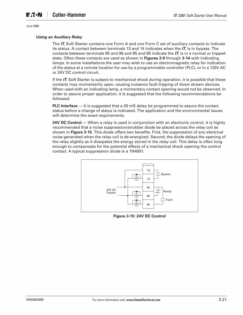
Using an Auxiliary Relay
The IT. Soft Starter contains one Form A and one Form C set of auxiliary contacts to indicate its status. A contact between terminals 13 and 14 indicates when the IT. is in bypass. The contacts between terminals 95 and 96 and 95 and 98 indicate the IT. is in a normal or tripped state. Often these contacts are used as shown in Figures 3-9 through 3-14 with indicating lamps. In some installations the user may wish to use an electromagnetic relay for indication of the status at a remote location for use by a programmable controller (PLC), or in a 120V AC or 24V DC control circuit.
If the IT. Soft Starter is subject to mechanical shock during operation, it is possible that these contacts may momentarily open, causing nuisance fault tripping of down stream devices. When used with an indicating lamp, a momentary contact opening would not be observed. In order to assure proper application, it is suggested that the following recommendations be followed:
PLC Interface — It is suggested that a 20 mS delay be programmed to assure the contact status before a change of status is indicated. The application and the environmental issues will determine the exact requirements.
24V DC Control — When a relay is used in conjunction with an electronic control, it is highly recommended that a noise suppression/snubber diode be placed across the relay coil as shown in Figure 3-15. This diode offers two benefits. First, the suppression of any electrical noise generated when the relay coil is de-energized. Second, the diode delays the opening of the relay slightly as it dissipates the energy stored in the relay coil. This delay is often long enough to compensate for the potential effects of a mechanical shock opening the control contact. A typical suppression diode is a 1N4001.
Figure 3-15: 24V DC Control
–
+
13
14R
95
96
98
Bypass
Ready24V DCSupply
Fault
R
R

IT. S801 Soft Starter User Manual
3-22 For more information visit: www.EatonElectrical.com MN03902008E
June 2006
120V AC Control — When a relay is used in conjunction with an electronic control, it is highly recommended that a noise suppressor be used across the relay coil. In the case of an AC coil, the noise suppressor is made up of a series connected resistor and capacitor as shown in Figure 3-16. Usually the delay in the relay opening is very small, so if the system is subject to shock, a delay should be added in the external control before the contact change of state is recognized. The resistor is rated 100 ohms at 0.5 watts. The capacitor is 0.25 µF at 250V AC.
Figure 3-16: 120V AC Control
Using a Supplemental Line Contactor
In some installations, it may be necessary to use an electromagnetic contactor in series with the soft starter. In this case, it is recommended that the contactor be placed on the load side of the soft starter. The contactor must be closed prior to starting the soft starter and remain closed until the Soft Starter has been stopped to ensure proper soft starter and system operation.
If an electromagnetic contactor is used on the line side of the soft starter, additional control circuitry must be supplied by the user when using edge level control to ensure the line power is supplied to the soft starter before control power (24V DC) is applied. If this sequence is not followed, the soft starter will fault on either a phase loss or zero voltage-crossing fault. This control scheme is illustrated in Figure 3-17.
–
+
13
14
95
96
98
Bypass
Ready120V ACSupply
Fault
R
R
R
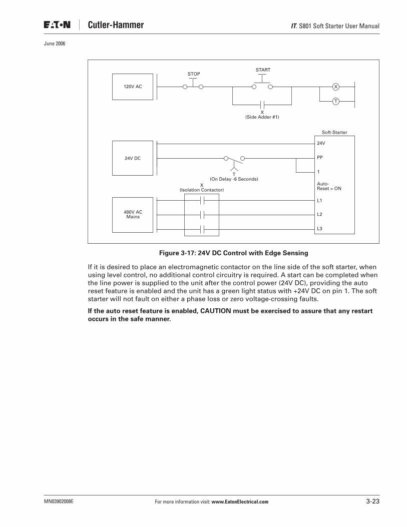
IT. S801 Soft Starter User Manual
MN03902008E For more information visit: www.EatonElectrical.com 3-23
June 2006
Figure 3-17: 24V DC Control with Edge Sensing
If it is desired to place an electromagnetic contactor on the line side of the soft starter, when using level control, no additional control circuitry is required. A start can be completed when the line power is supplied to the unit after the control power (24V DC), providing the auto reset feature is enabled and the unit has a green light status with +24V DC on pin 1. The soft starter will not fault on either a phase loss or zero voltage-crossing faults.
If the auto reset feature is enabled, CAUTION must be exercised to assure that any restart
occurs in the safe manner.
24V
Soft-Starter
PP
1
Auto-Reset = ON
L1
L2
L3
480V ACMains
24V DC
X(Isolation Contactor)
X(Side Adder #1)
T(On Delay -6 Seconds)
X
T
120V AC
STARTSTOP

IT. S801 Soft Starter User Manual
3-24 For more information visit: www.EatonElectrical.com MN03902008E
June 2006

IT. S801 Soft Starter User Manual
MN03902008E For more information visit: www.EatonElectrical.com 4-1
June 2006
Chapter 4 — Specifications
Environmental
Table 4-1: Environmental Specifications
Physical
Table 4-2: Weight
Table 4-3: Agency Standards and Certifications
Item Specification
Temperature Range —OperatingStorage
-40°F – 122°F (-40°C – 50°C)-58°F – 158°F (-50°C – 70°C)
Elevation Up to 6,600 ft. (2000m). Above 6,600 ft. (2000m), derate 0.5% per 330 ft. (100m)
Humidity Functional to 95% non-condensing
Operating Orientation Any
Pollution Degree IEC 60947-1 3
Shock Resistance 15g in any direction
Vibration Resistance 3g in any direction
FrameSize Weight of Unit
N 5.8 Lbs. (2.6 Kg)
R 10.5 Lbs. (4.8 Kg)
T and U 48 Lbs. (21.8 Kg) with lugs
41 Lbs. (18.6 Kg) without lugs
V 103 Lbs. (46.8 Kg) with lugs
91 Lbs. (41.4 Kg) without lugs
Standard Certifications
UL UL 508
CSA CSA 22.2 – 14 – 1995
IEC 60947-4-2
CE See Table 4-4

IT. S801 Soft Starter User Manual
4-2 For more information visit: www.EatonElectrical.com MN03902008E
June 2006
CE Conformance
Table 4-4: EMC Immunity
1. The 24V DC power supply must be grounded.
2. Add ferrite, Fair-Rite #0444173551 to DC Power Leads and Control I/O Leads (all through one ferrite) at S801 with two passes through ferrite of the DC Power Leads, and a single pass through ferrite of the I/O Control Leads.
3. Add ferrite, Fair-Rite #0443167251 to Load Leads at S801 with two passes through ferrite.
Immunity Severity Level
Electrostatic DischargeIEC 61000-4-2
4 kV contact discharge8 kV air discharge
Electromagnetic FieldIEC 61000-4-3
10 V/m80 – 1000 MHz2 angles
Fast Transient BurstsIEC 61000-4-4
2 kV, 5 kHz rep, 2 min intervals
1.2/50 µS – 8/20 µS SurgesIEC 61000-4-5
2 kV Line to earth1 kV Line to Line1 minute intervals
Conducted RFIEC 61000-4-6
10 V rms.15 – 80 MHz
50 Hz Magnetic Field IEC 61000-4-8
N/A
Voltage dipsInterruptIEC 61000-4-11
30% dip @10 mS60% dip @100 mS100% interrupt @5 S
Emissions
Radiated EN 55011, Class A
Conducted EN 55011, Class A

IT. S801 Soft Starter User Manual
MN03902008E For more information visit: www.EatonElectrical.com 4-3
June 2006
Short Circuit Ratings
Table 4-5: Short Circuit Ratings
� Catalog No. S801T__V3S devices are UL Listed and suitable for use on a circuit capable of delivering not more than 18 kA symmetrical amperes, 690 volts maximum, when protected by a Ferraz-Shawmut Amp-Trap Form 101 (Cat. No. A70QS800-4) 800 Amp, 700 Volt Semiconductor Protection Fuse.
� Catalog No. S801V__V3S devices are UL Listed and suitable for use on a circuit capable of delivering not more than 42 kA 690 volts maximum, when protected by a Ferraz-Shawmut Type PSC (Cat. No. A070URD73I1600) 1600 Amp, 700 Volt Semiconductor Protection Fuse.
� Catalog No. S801T__V3S devices tested per IEC 60947-4-2 to Type 1 Short Circuit Withstand Requirements to 18 kA, 690 volts with Cutler-Hammer Cat. No. NW3800T33W 800 Amp 690 Volt circuit breaker.
� Catalog No. S801V__V3S devices tested per IEC 60947-4-2 to Type 1 Short Circuit Withstand Requirements to 42 kA, 690 volts with Cutler-Hammer Cat. No. RW420T33W 2 kA 690 Volt circuit breaker.
Note: Short circuit protection must be applied on the line side of the soft starter.
Soft StarterFrame Size
Three-Phase Short Circuit Rating
240V 480V 600V 690V
N 10 kA 10 kA 10 kA —
R 10 kA 10 kA 10 kA —
T 18 kA 18 kA 18 kA � �
U 30 kA 30 kA 30 kA —
V 42 kA 42 kA 42 kA � �

IT. S801 Soft Starter User Manual
4-4 For more information visit: www.EatonElectrical.com MN03902008E
June 2006

IT. S801 Soft Starter User Manual
MN03902008E For more information visit: www.EatonElectrical.com 5-1
June 2006
Chapter 5 — Functional Description
Power
The S801 Soft Starter controls the voltage applied to a three-phase induction motor in order to control the starting torque and provide a smooth starting characteristic. Within the soft starter are three power poles, each of which includes a set of anti-parallel SCRs (thyristors) in parallel with a contact. During a start, the conduction periods of the SCRs are continuously adjusted to apply a gradually increasing voltage to the motor, resulting in gradually increasing torque and a smooth start. As the motor reaches its rated speed, the power pole contacts are closed, bypassing the SCRs for the most efficient operation.
Figure 5-1: Soft Starter SCRs
For each start, the length of time the SCRs are conducting current as well as the magnitude of that current determine how hot the SCRs will get. Between successive starts the SCRs must cool down to avoid exceeding their thermal limits. Appendix B (Ratings, Cooling and Power Losses) gives the S801’s application ratings for various starting conditions. Staying within these specified limits should avoid over temperature trips.
When the S801 control circuit senses that the internal temperature has increased above a preset value, internal fans are tuned on to assist in cooling. To maximize fan life the fans are only turned on when needed. Further discussion of fan operation can be found in Appendix B.
Control
The software contained in the S801 IT. Soft Starter is the heart of the product. This software allows you to control nearly every aspect of the soft starter’s functionality. In this section, various features and protection options are described.
Starting Options
The following starting choices are available in the S801:
Note that the motor current observable with a standard RMS indicating meter may not be correct because of its non-sinusoidal nature during starting. It is suggested that the starting current be estimated from the T1 or T2 setting and the tabulation in Table 6-1 on Page 6-4.
L3
Motor3-PhaseAC LineVoltage
L2
L1
T3
T2
T1

IT. S801 Soft Starter User Manual
5-2 For more information visit: www.EatonElectrical.com MN03902008E
June 2006
Soft Start with Selectable Kick Start
This mode of operation works in both the Ramp Start and Current Limit Start modes. A kick-start (or boost) allows the motor to draw greater current to develop additional torque to breakaway a high friction load.
The kick start torque is programmable from 5% to 85% of motor’s across-the-line locked rotor torque, corresponding to 23% to 92% of the motor’s across-the-line locked rotor current. The factory default is 5%. The kick start time is programmable from 0.0 seconds to 2.0 seconds.
If no kick-start is desired, set the kick start torque (T1) and kick start time (tk) to zero.
Figure 5-2: Selectable Kick-Start
Ramp Start
This mode of operation is the most commonly used form of soft start.
The motor is accelerated using an initial torque (T2) value of 5% to 85% of across-the-line locked rotor torque, corresponding to 23% to 92% of the motor’s across-the-line locked rotor current. The factory default is 35%. The torque is then increased over the range of the programmed acceleration ramp start time (tr) by increasing the motor voltage. This can be programmed from 0.5 to 180 seconds. The factory default is 9 seconds. The first half of the control adjusts from 0.5 to 20 seconds, the next quarter from 20 to 60 seconds, and the last quarter from 60 to 180 seconds. The unit will limit current to the specified torque. When the motor is up to speed, it will go into bypass.
T1
Bypass
Time (Seconds)
Start Run
To
rqu
e
tk trT2
Kick Start

IT. S801 Soft Starter User Manual
MN03902008E For more information visit: www.EatonElectrical.com 5-3
June 2006
Figure 5-3: Ramp Start
Current Limit Start
This mode is typically used when it is necessary to limit the maximum current during startup.
Starting torque (T2) can be programmed from 5% to 85% of the motor’s across-the-line locked rotor torque, corresponding to 23% to 92% of the motor’s across-the-line locked rotor current. The T2 default is 35%. The ramp time is programmable from 0.5 to 180 seconds. The factory default is 9 seconds. The control is not linear to allow finer setting of short ramp times. The first half of the control adjusts from 0.5 to 20 seconds, the next quarter from 20 to 60 seconds, and the last quarter from 60 to 180 seconds. The unit will limit current to the specified torque. When the motor is up to speed, it will go into bypass.
Figure 5-4: Current Limit Start
Pump Start
The pump control option is addressed in Appendix D.
InitialTorque
(T2)
Bypass
Time (Seconds)
100%
Start Run
To
rqu
e
tr
InitialTorque
(T2)
Bypass
Time (Seconds)
100%
Start Run
To
rqu
e
tr
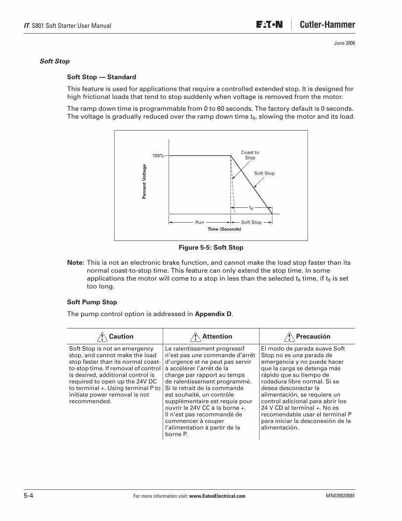
IT. S801 Soft Starter User Manual
5-4 For more information visit: www.EatonElectrical.com MN03902008E
June 2006
Soft Stop
Soft Stop — Standard
This feature is used for applications that require a controlled extended stop. It is designed for high frictional loads that tend to stop suddenly when voltage is removed from the motor.
The ramp down time is programmable from 0 to 60 seconds. The factory default is 0 seconds. The voltage is gradually reduced over the ramp down time ts, slowing the motor and its load.
Figure 5-5: Soft Stop
Note: This is not an electronic brake function, and cannot make the load stop faster than its normal coast-to-stop time. This feature can only extend the stop time. In some applications the motor will come to a stop in less than the selected ts time, if ts is set too long.
Soft Pump Stop
The pump control option is addressed in Appendix D.
Soft Stop is not an emergency stop, and cannot make the load stop faster than its normal coast-to-stop time. If removal of control is desired, additional control is required to open up the 24V DC to terminal +. Using terminal P to initiate power removal is not recommended.
Le ralentissement progressif n’est pas une commande d’arrêt d’urgence et ne peut pas servir à accélérer l’arrêt de la charge par rapport au temps de ralentissement programmé. Si le retrait de la commande est souhaité, un contrôle supplémentaire est requis pour ouvrir le 24V CC à la borne +. Il n’est pas recommandé de commencer à couper l’alimentation à partir de la borne P.
El modo de parada suave Soft Stop no es una parada de emergencia y no puede hacer que la carga se detenga más rápido que su tiempo de rodadura libre normal. Si se desea desconectar la alimentación, se requiere un control adicional para abrir los 24 V CD al terminal +. No es recomendable usar el terminal P para iniciar la desconexión de la alimentación.
ts
100%
Run Soft Stop
Pe
rce
nt
Vo
lta
ge
Time (Seconds)
Coast toStop
Soft Stop
Caution! Attention! Precaución!
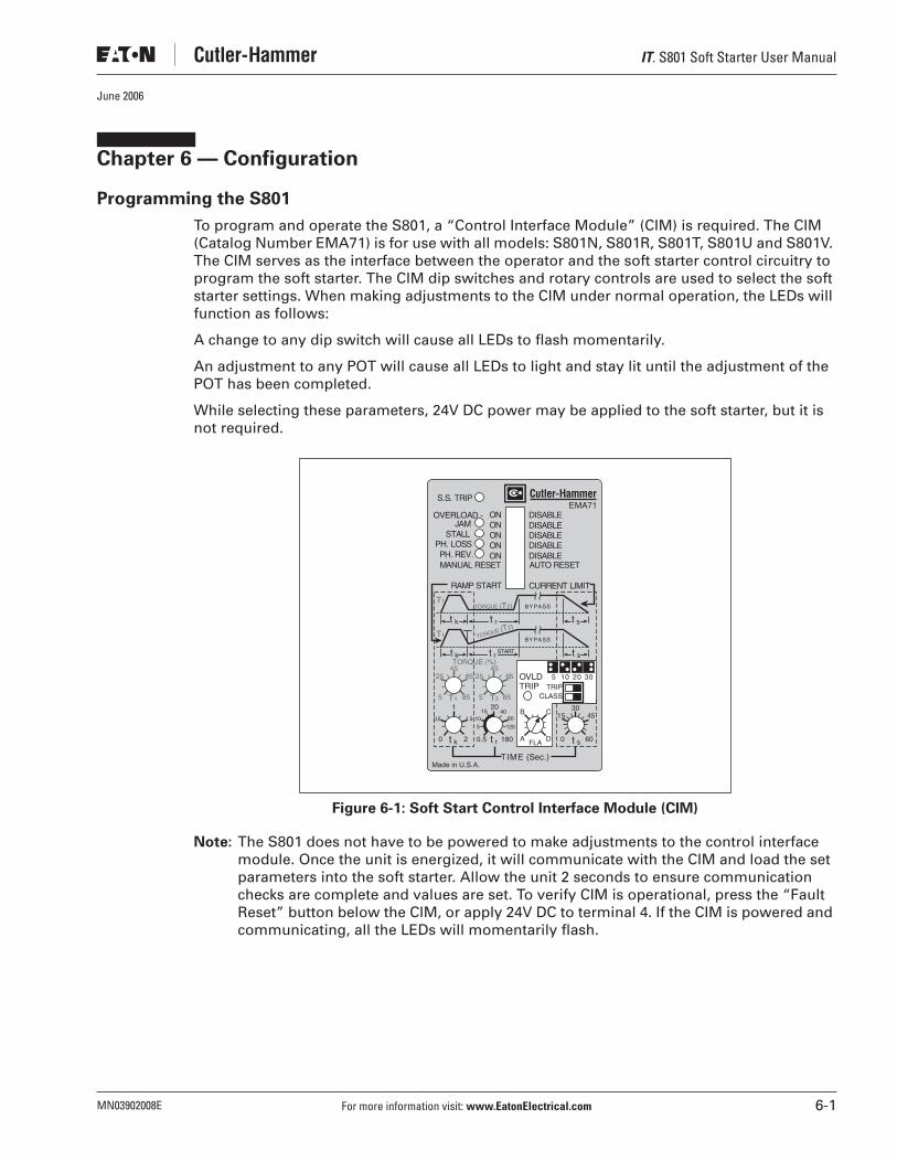
IT. S801 Soft Starter User Manual
MN03902008E For more information visit: www.EatonElectrical.com 6-1
June 2006
Chapter 6 — Configuration
Programming the S801
To program and operate the S801, a “Control Interface Module” (CIM) is required. The CIM (Catalog Number EMA71) is for use with all models: S801N, S801R, S801T, S801U and S801V. The CIM serves as the interface between the operator and the soft starter control circuitry to program the soft starter. The CIM dip switches and rotary controls are used to select the soft starter settings. When making adjustments to the CIM under normal operation, the LEDs will function as follows:
A change to any dip switch will cause all LEDs to flash momentarily.
An adjustment to any POT will cause all LEDs to light and stay lit until the adjustment of the POT has been completed.
While selecting these parameters, 24V DC power may be applied to the soft starter, but it is not required.
Figure 6-1: Soft Start Control Interface Module (CIM)
Note: The S801 does not have to be powered to make adjustments to the control interface module. Once the unit is energized, it will communicate with the CIM and load the set parameters into the soft starter. Allow the unit 2 seconds to ensure communication checks are complete and values are set. To verify CIM is operational, press the “Fault Reset” button below the CIM, or apply 24V DC to terminal 4. If the CIM is powered and communicating, all the LEDs will momentarily flash.
TORQUE (%)
T2T1
T1
T1TORQUE (T2)
TORQUE (T2)
45
5 85
652545
5 85
6525
30
0 60
TIME (Sec.)
t k0 2
RAMP START
MANUAL RESET
JAMSTALL
PH. REV.PH. LOSS
ONONONON
DISABLEDISABLEDISABLEAUTO RESET
CURRENT LIMIT
DISABLE
START
Made in U.S.A.
ON DISABLEOVERLOAD -
20
0.5
EMA71S.S. TRIP
60 15 45
5 10 20 30
BYPASS
BYPASS
t r t s
t k t r t s
t k t r t s
10
1
1.50.5
180
4015
1205
OVLDTRIP TRIP
CLASS
B
A
C
DFLA

IT. S801 Soft Starter User Manual
6-2 For more information visit: www.EatonElectrical.com MN03902008E
June 2006
Trip Class
To begin programming the S801, choose the trip class and FLA settings desired.
The trip class setting is made by moving the dip switches into the appropriate position to match the class overload desired.
Figure 6-2: Setting Trip Class and FLA on the CIM
Find the motor FLA value on Table A-1. Set the FLA dial to the proper position. See Figure A-1 for the thermal overload trip curves.
Example: For a trip Class 5, both DIP switches should be set up to the left.
Protective Features
You may choose to enable or disable each of the following motor protective features found at the top of the CIM. These include:
● Overload● Jam● Stall● Phase Loss — Load Disconnect● Phase Reversal Protection
To enable a feature, move its dip switch to “ON.”
To disable a feature, move its dip switch to “DISABLE.”
Note: Disabling any of the motor protective features does not disable any of the IT. Soft Starter’s protective features as shown in the flash code table on Page 8-5.
Manual/Auto Fault Reset
Select auto or manual reset on the Control Interface Module.
When a fault is present, if auto-reset is on, it will attempt to reset the fault every 2.5 seconds. If the cause of the fault has been eliminated, the fault will be reset. If the fault has not been eliminated, the fault status will be maintained. After the fault is reset, the soft starter can be restarted as normal.
To manually reset the fault after its cause has been cleared if auto reset is off, press the FAULT RESET button below the CIM or apply 24V DC to terminal 4 of the control terminal block.
Note: The motor does NOT automatically restart after a fault is reset UNLESS the soft starter is equipped for Level Sensing Control. See “Edge and Level Sensing Control” section on Page 3-20.
OVLDTRIP TRIP
CLASS
5
B
A
C
DFLA
10 20 30

IT. S801 Soft Starter User Manual
MN03902008E For more information visit: www.EatonElectrical.com 6-3
June 2006
Special Function S.F.
On occasion, a special function option is purchased and installed on the IT. soft starter. The special function may be enabled or disabled with this dip switch.
The pump control option is a special function option. It is addressed in Appendix D.
Options
Edge sensing is denoted with an “S” in the last character of catalog number. Ex. S801…………N3S
Level sensing is denoted with an “B” in the last character of catalog number. Ex. S801…………N3B
690V rated S801 are denoted with an “V” in the last part of catalog number (not available in the U-Frame). Ex. S801…………V3S
Programming the Start
This procedure covers programming the start characteristics of the soft starter. There are two configurations to choose from.
● Ramp Start sequence
● Current Limit Start sequence
Set the bottom dip switch to make your choice.
A kick-start is available for either ramp or current limit start.
The pump control option includes a variation of the ramp start suitable for centrifugal pump applications. See Appendix D for specific information.
Programming the Kick Start Sequence
Kick Start
The first set of parameters to be set on the CIM is for Kick Start, Figure 6-3. This feature is designed to assist the starter in overcoming a high-friction load and break the rotor free, prior to the normal start.
Two parameters must be set. The kick start torque value (T1) can be set from 5% to 85% of the motor’s across-the-line starting torque. This setting also equates to a percentage of locked rotor current of 23% to 92%.
For example: For a motor with an across-the-line locked rotor current of 6 x FLA, the initial current would be limited to 5.5 x FLA or (0.92 x 6 x FLA) for a T1 setting of 85% or 92% of locked rotor current. The across-the-line locked rotor torque versus equivalent starting current values are found in Table 6-1.
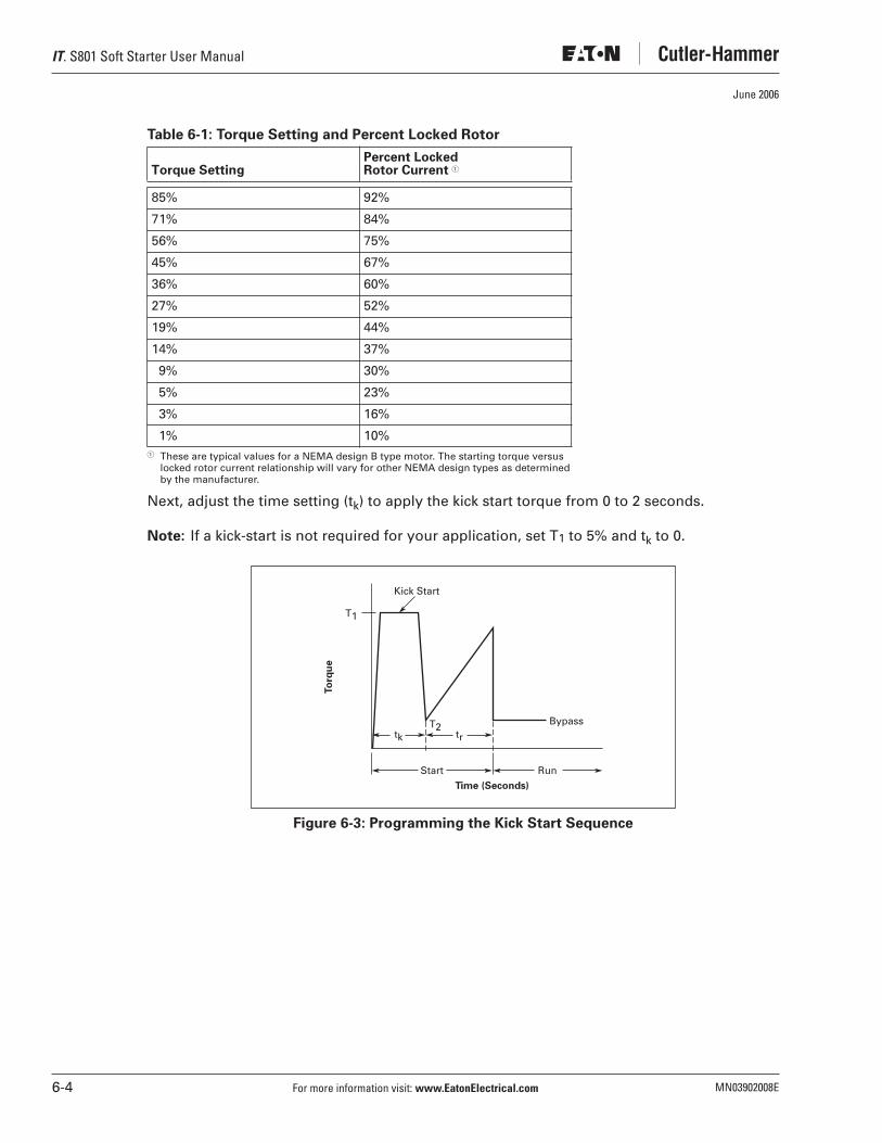
IT. S801 Soft Starter User Manual
6-4 For more information visit: www.EatonElectrical.com MN03902008E
June 2006
Table 6-1: Torque Setting and Percent Locked Rotor
� These are typical values for a NEMA design B type motor. The starting torque versuslocked rotor current relationship will vary for other NEMA design types as determinedby the manufacturer.
Next, adjust the time setting (tk) to apply the kick start torque from 0 to 2 seconds.
Note: If a kick-start is not required for your application, set T1 to 5% and tk to 0.
Figure 6-3: Programming the Kick Start Sequence
Torque SettingPercent LockedRotor Current �
85% 92%
71% 84%
56% 75%
45% 67%
36% 60%
27% 52%
19% 44%
14% 37%
9% 30%
5% 23%
3% 16%
1% 10%
T1
Bypass
Time (Seconds)
Start Run
To
rqu
e
tk trT2
Kick Start
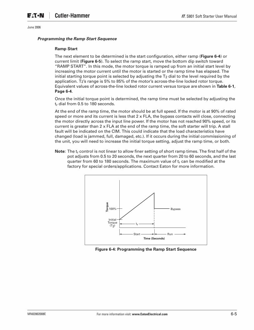
IT. S801 Soft Starter User Manual
MN03902008E For more information visit: www.EatonElectrical.com 6-5
June 2006
Programming the Ramp Start Sequence
Ramp Start
The next element to be determined is the start configuration, either ramp (Figure 6-4) or current limit (Figure 6-5). To select the ramp start, move the bottom dip switch toward “RAMP START”. In this mode, the motor torque is ramped up from an initial start level by increasing the motor current until the motor is started or the ramp time has elapsed. The initial starting torque point is selected by adjusting the T2 dial to the level required by the application. T2’s range is 5% to 85% of the motor’s across-the-line locked rotor torque. Equivalent values of across-the-line locked rotor current versus torque are shown in Table 6-1, Page 6-4.
Once the initial torque point is determined, the ramp time must be selected by adjusting the tr dial from 0.5 to 180 seconds.
At the end of the ramp time, the motor should be at full speed. If the motor is at 90% of rated speed or more and its current is less that 2 x FLA, the bypass contacts will close, connecting the motor directly across the input line power. If the motor has not reached 90% speed, or its current is greater than 2 x FLA at the end of the ramp time, the soft starter will trip. A stall fault will be indicated on the CIM. This could indicate that the load characteristics have changed (load is jammed, full, damaged, etc.). If it occurs during the initial commissioning of the unit, you will need to increase the initial torque setting, adjust the ramp time, or both.
Note: The tr control is not linear to allow finer setting of short ramp times. The first half of the pot adjusts from 0.5 to 20 seconds, the next quarter from 20 to 60 seconds, and the last quarter from 60 to 180 seconds. The maximum value of tr can be modified at the factory for special orders/applications. Contact Eaton for more information.
Figure 6-4: Programming the Ramp Start Sequence
InitialTorque
(T2)
Bypass
Time (Seconds)
100%
Start Run
To
rqu
e
tr

IT. S801 Soft Starter User Manual
6-6 For more information visit: www.EatonElectrical.com MN03902008E
June 2006
Programming the Current Limit Start
The process for programming with the Current Limit Start (Figure 6-5), is similar to the process for the Ramp Start.
To select the Current Limit Start option, move the dip switch to the right. This will activate the current limit start-up profile.
In the current limit startup mode, you set a maximum current during the start. This value (T2) can be set from 5% to 85% of the across-the-line locked rotor torque. (See Table 6-1, Page 6-4 for values). Next, set the start time (tr) for the start. This value can be set from 0.5 to 180 seconds.
Note: The ramp time is set to zero automatically.
At the end of the ramp, the motor should be at full speed. If the motor is at 90% of rated speed or greater of this value and current is less than 2 x FLA, the bypass contacts will then close, and the unit will run at full speed. If it has not reached 90% of speed at the end of ramp, the unit will trip off line and you will receive a stall indication on the control interface module. This could indicate that the load characteristics have changed (load is jammed, full, damaged, etc.). If it occurs during initial commissioning of the unit, you will need to increase the current limit setting, increase the length of the ramp, or both to allow enough time and energy to bring the motor up to speed.
Note: The tr pot is not linear to allow finer setting of short ramp times. The first half of the control adjusts from 0.5 to 20 seconds, the next quarter from 20 to 60 seconds, and the last quarter from 60 to 180 seconds. The maximum value of tr can be modified at the factory for special orders/applications. Contact Eaton for more information.
Figure 6-5: Programming the Current Limit Start
InitialTorque
(T2)
Bypass
Time (Seconds)
100%
Start Run
To
rqu
e
tr
Ramp Set to 0

IT. S801 Soft Starter User Manual
MN03902008E For more information visit: www.EatonElectrical.com 6-7
June 2006
Programming the Soft Stop
Soft Stop
The last item to be programmed is the soft stop. This feature slowly reduces the voltage applied to the motor to extend its stop time.
The soft stop feature has one setting, ramp time ts, programmable from 0 to 60 seconds. If ts is set to 0 when a stop command is given, the bypass contacts will open and the de-energized motor will coast to a stop as if connected to an electromagnetic starter. If ts is set longer than this coast down time, the soft stop output voltage will linearly decrease upon a stop command, extending the stop time. Note that in some applications the motor will come to a stop in less than the selected ts time if ts is set too long.
Figure 6-6: Programming the Soft Stop
The pump control option includes a special soft stop feature intended to prevent water hammer upon shutdown in centrifugal pump applications. See pump control option in Appendix D, for specific information.
Soft Stop is not an emergency stop. If a quick stop is desired, additional control is required to open up the 24V DC to terminal +. Using terminal P for a quick stop is not recommended.
Le ralentissement progressif n’est pas une commande d’arrêt d’urgence. Si un arrêt rapide et désiré, un contrôle supplémentaire est requis pour ouvrir le 24V CC à la borne +. Il n’est pas recommandé d’utiliser la borne P pour un arrêt rapide.
La parada suave no es una parada de emergencia. Si desea una parada rápida, se requiere control adicional para suministrar 24 V DC al terminal +. No se recomienda el uso del terminal P para una parada rápida.
Soft Stop does not provide any braking. It cannot cause the motor and its load to stop faster than their normal unpowered coast down time.
Le ralentissement progressif n’assure aucun freinage. Il ne peut pas servir à accélérer l’arrêt du moteur et sa charge par rapport au temps de ralentissement programmé.
La parada suave no proporciona ningún tipo de freno. No puede hacer que el motor y su carga se detengan con mayor rapidez que su tiempo normal de funcionamiento por inercia.
Caution! Attention! Precaución!
Caution! Attention! Precaución!
ts
100%
Run Soft Stop
Pe
rce
nt
Vo
lta
ge
Time (Seconds)
Coast toStop
Soft Stop

IT. S801 Soft Starter User Manual
6-8 For more information visit: www.EatonElectrical.com MN03902008E
June 2006

IT. S801 Soft Starter User Manual
MN03902008E For more information visit: www.EatonElectrical.com 7-1
June 2006
Chapter 7 — Setup and Starting
Line Power
● Line power must be applied prior to the application of the 24V DC control power to prevent a phase loss or zero voltage crossing protection fault.
● Terminal P must have 24V DC applied to ENABLE the soft starter.
● The soft starter will start when 24V DC is applied to terminal P and either terminal 1 or 2 goes from 0V DC to 24V DC.
● Remove 24V DC from terminal P to initiate a stop.
● If either terminal 1 or 2 remains connected to 24V DC when terminal P is opened, the soft starter will stop.
● Terminals 1 through 4 are activated by momentarily applying 24V DC.
● If either terminal 1 or 2 remains connected to 24V DC when terminal P is opened, the soft starter will stop.
● On the R, T, U and V frame soft starters, when the bypass contactors close, a momentary sound similar to contactor chattering can be heard. The three single-phase contactors closing in a staggered manner over a very short period of time cause this sound. This is part of normal operation, and should not be misinterpreted as a dirty pick-up.
● For two-wire control, jumper terminals P and 1 together.
Jog
● Terminal P must have 24V DC applied.
● Terminal 2 is edge sensitive. This means that there must be a transition for 0 to 24V DC to jog.
● In jog, the unit will follow the normal start ramp as long as terminal 2 is at 24V DC.
● To stop, remove the 24V DC from terminal 2.
● Jog operates the same as a normal start, except that the bypass contactors will not close and the soft stop is not functional.
Note: Jog is only intended for short term jogging of the motor and not for long term two-wire control. For two-wire control, tie terminals P and 1 together and connect to 24V DC to start and disconnect from 24V DC to stop.

IT. S801 Soft Starter User Manual
7-2 For more information visit: www.EatonElectrical.com MN03902008E
June 2006
IT. S801 Soft Starter User Manual
MN03902008E For more information visit: www.EatonElectrical.com 8-1
June 2006
Chapter 8 — Troubleshooting
General
In this section of the manual, we present a procedure you can follow to diagnose a problem with your S801.
While many potential situations are outlined in this section, it is possible you may run into a problem that is not covered here. If you have worked through the following troubleshooting procedure and find that you require further assistance, please contact Eaton.
Please have the following information ready when you call:
Before You Begin to Troubleshoot
We highly recommend that you read this entire section of the manual before you begin to troubleshoot the IT. Soft Starter.
You may want to obtain the following equipment to aid you in troubleshooting:
● Multimeter
● Clamp-on ammeter
Always assume the S801 has high voltage applied and take proper precautions while troubleshooting the soft starter and associated equipment. Read all precautions at the front of this manual before starting the troubleshooting process.
Order No. (if available):
Catalog Number:
Style Number:
Serial Number:
CIM DIP Switch Settings:
CIM Pot Settings:
Make sure you read and understand the procedures in this manual before you attempt to operate or set up the equipment.
Bien lire et comprendre les procédures contenues dans ce manuel avant de tenter le fonctionnement ou la mise en place de l’équipement.
Asegúrese de leer y entender los procedimientos en este manual antes de intentar operar o configurar el equipo.
Do not work on energized equipment unless absolutely required. If troubleshooting procedure requires equipment to be energized, all work must be performed by properly qualified personnel, following appropriate safety practices and precautionary measures.
Ne pas travailler sur d’équipement sous tension sauf si c’est absolument nécessaire. Si des méthodes de dépannage exigent que l’équipement soit sous tension, tout travail doit être faire par du personnel qualifié, suivant des pratiques de sécurité et des mesures de précaution appropriées.
No trabaje en equipos en funcionamiento, a menos que sea absolutamente necesario. Si un procedimiento de solución de problemas requiere que el equipo permanezca encendido, todo el trabajo lo debe realizar personal adecuadamente calificado, respetando las prácticas de seguridad y las medidas preventivas correspondientes.
Warning Avertissement Advertencia
Danger High Voltage Danger Haute Tension Peligro alto voltaje

IT. S801 Soft Starter User Manual
8-2 For more information visit: www.EatonElectrical.com MN03902008E
June 2006
Define the Problem
There are four basic problem types you may encounter with the S801. To begin, select the situation below that most closely matches your problem.
1. The IT. Soft Starter fails to start. No power is applied to the motor.
Go to Figure 8-1 — Troubleshooting Flowchart #1.
2. The IT. Soft Starter trips during start-up, or fails to reach rated speed before going into
bypass.
Go to Figure 8-1 — Troubleshooting Flowchart #1.
3. The IT. Soft Starter trips or stops running during normal running conditions.
Go to Figure 8-1 — Troubleshooting Flowchart #1.
4. None of the above situations match the problem.
Go to Figure 8-2 — Troubleshooting Flowchart #2.
Figure 8-1: Troubleshooting Flowchart #1
Start
Off Green
Red
What is thecondition of the
status LED?
Are there anyred LEDs
on the CIM?
Consult”Status LED Off”,
Table 8-1
Consult”Status LED Green”,
Table 8-2
Consult”Fault Shown on CIM”,
Table 8-3
Consult”Fault Not Shown on CIM”,
Table 8-5
Yes No

IT. S801 Soft Starter User Manual
MN03902008E For more information visit: www.EatonElectrical.com 8-3
June 2006
Figure 8-2: Troubleshooting Flowchart #2
Table 8-1: Troubleshooting — Status LED Off
Table 8-2: Troubleshooting — Status LED Green
Start
Yes NoDoes theunit run, evenintermittently?
ConsultAppropriate
Symptom Table
OtherSymptom Not
Listed
Bypass Fails toClose/Chatters
Noise FromIT. Soft Starter Yes
NoIs theIT. Soft StarterStatus LED Lit?
Consult”Status LED Off”,
Table 8-1
ConsultFigure A-1
ExcessNoise/Vibration
in Motor
Unit WillNot StopRunning
Symptom/Indication Possible Problem Possible Solution
No indication on the unit or on the CIM.
Loss of 24V DC power.
Check control wiring.
Verify 24V DC power available from power supply.
Check power supply fuse/circuit breaker.
Failed CIM. Disconnect the CIM.
If the Status LED lights, replace the CIM.
If not, control board may be defective.
Contact Eaton.
Failed control board. Contact Eaton.
No status light, but CIM is powered.
Failed LED indication.
Reset the unit, verify operation.
Cycle 24V DC control power to the unit.
Symptom/Indication Possible Problem Possible Solution
Status LED green, no indication on the CIM.
Line power fault. Check wiring connection on load and line side.
Check line power breakers/fuses.
Verify 24V DC power on “P” terminal. Then, verify power is cycled to terminal 1.

IT. S801 Soft Starter User Manual
8-4 For more information visit: www.EatonElectrical.com MN03902008E
June 2006
Table 8-3: Troubleshooting — Fault Shown on CIM
Symptom/Indication Possible Problem Possible Solution
S.S. LED is lit.
(Overtemperature tr setting, hardware failure or load disconnect.)
High temperature — see flash codes.
Allow system to cool down with 24V DC applied to + and -.
Verify operation of unit cooling fans.
Clear any blockage or restriction of air flow.
Possible hardware failure — see flash codes.
If code 32 is indicated, check actual motor start time vs. tr set time. tr should not be set more than 2 – 3 seconds longer than the actual motor start time. Reset tr.
Contact Eaton.
Load disconnect. Check shaft coupler between motor and load.
JAM LED is lit. Fault exists in memory.
Press the RESET button located below the CIM to clear the fault.
Current has exceeded Jam program level.
Clear the cause of the jam.
FLA setting too low for application. Check that it matches motor nameplate current.
STALL LED is lit. Fault exists in memory.
Press the RESET button located below the CIM to clear the fault.
Unit failed to reach rated speed (90%) at end of ramp.
Clear the cause of the stall in the application.
Verify ramp time is sufficient for application.
Verify initial torque setting is sufficient for application.
FLA setting too low for application. Check that it matches motor nameplate current.
PH. LOSS LED is lit.
(Phase loss or unbalanced line current.)
One or more line voltages are missing or low.
Verify proper line voltage present and that no other equipment was affected.
Confirm line power connections are correct and tight.
Check line power fuses, circuit breakers and disconnects.
Press the RESET button located below the CIM to clear the fault.
Phase voltages or currents unbalanced.
Check same solutions as for phase loss.
Confirm motor current balanced when connected across the line with balanced line voltage. If not, replace motor.
If line voltage balance but load voltage not, contact Eaton.
Check load connections at soft starter and at motor terminal box.
PH REV LED is lit. Line voltage is not in ABC configuration.
Verify proper wiring arrangement.
OVLD TRIP LED is lit.
Motor is overloaded. Check motor for load problems.
FLA not set to motor ratings.
Verify that the FLA setting matches the motor nameplate current. (Consider any Service Factor being used.)
Trip class set improperly.
Adjust trip class setting on CIM.
Fault exists in memory.
Press the RESET button located below the CIM to clear the fault. If the fault remains, maintain 24V DC power applied to the unit, and allow the system to cool down for at least 9 minutes and try again.
Failed current sensor. Contact Eaton.
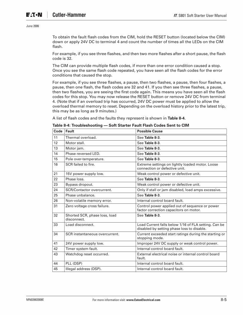
IT. S801 Soft Starter User Manual
MN03902008E For more information visit: www.EatonElectrical.com 8-5
June 2006
To obtain the fault flash codes from the CIM, hold the RESET button (located below the CIM) down or apply 24V DC to terminal 4 and count the number of times all the LEDs on the CIM flash.
For example, if you see three flashes, and then two more flashes after a short pause, the flash code is 32.
The CIM can provide multiple flash codes, if more than one error condition caused a stop. Once you see the same flash code repeated, you have seen all the flash codes for the error conditions that caused the stop.
For example, if you see three flashes, a pause, then two flashes, a pause, then four flashes, a pause, then one flash, the flash codes are 32 and 41. If you then see three flashes, a pause, then two flashes, you are seeing the first code again. This means you have seen all the flash codes for this stop. You may now release the RESET button or remove 24V DC from terminal 4. (Note that if an overload trip has occurred, 24V DC power must be applied to allow the overload thermal memory to reset. Depending on the overload history prior to the latest trip, this may be as long as 9 minutes.)
A list of flash codes and the faults they represent is shown in Table 8-4.
Table 8-4: Troubleshooting — Soft Starter Fault Flash Codes Sent to CIM
Code Fault Possible Cause
11 Thermal overload. See Table 8-3.
12 Motor stall. See Table 8-3.
13 Motor jam. See Table 8-3.
14 Phase reversed LED. See Table 8-3.
15 Pole over-temperature. See Table 8-3.
16 SCR failed to fire. Extreme settings on lightly loaded motor. Loose connection or defective unit.
21 15V power supply low. Weak control power or defective unit.
22 Phase loss. See Table 8-3.
23 Bypass dropout. Weak control power or defective unit.
24 SCR/Contactor overcurrent. Only if stall or jam disabled, load amps excessive.
25 Phase unbalance. See Table 8-3.
26 Non-volatile memory error. Internal control board fault.
31 Zero voltage cross failure. Control power applied out of sequence or power factor correction capacitors on motor.
32 Shorted SCR, phase loss, load disconnect.
See Table 8-3.
33 Load disconnect. Load Current falls below 1/16 of FLA setting. Can be disabled by setting phase loss to disable.
34 SCR instantaneous overcurrent. Current exceeded start ratings during the starting or stopping mode.
41 24V power supply low. Improper 24V DC supply or weak control power.
42 Timer system fault. Internal control board fault.
43 Watchdog reset occurred. External electrical noise or internal control board fault.
44 PLL (DSP) Internal control board fault.
45 Illegal address (DSP). Internal control board fault.

IT. S801 Soft Starter User Manual
8-6 For more information visit: www.EatonElectrical.com MN03902008E
June 2006
Table 8-5: Troubleshooting — Fault Not Shown on CIM
Table 8-6: Troubleshooting — Excess Noise/Vibration in Motor
Table 8-7: Troubleshooting — Audible Noise from Soft Starter — Bypass Fails to Close/Chatters
Symptom/Indication Possible Problem Possible Solution
Status LED is lit, no indication on CIM.
No communication with CIM.
Verify connection between soft starter and CIM. Press the RESET button (located below the CIM). All LEDs should momentarily light.
Sensor failure. Cycle 24V DC control power to the unit. Allow unit to reset.
Bypass opened during run.
Press the RESET button (located below the CIM) to reset the fault.
Verify that the 24V DC power supply rating is large enough to close the bypass contacts with a minimum output rating of 250 watts for 0.15 seconds.
Symptom/Indication Possible Problem Possible Solution
Motor vibration during start-up.
Load fluctuations. Check load conditions.
Misapplication. Verify that motor is a standard squirrel cage induction motor.
Ramp time set too low for application.
Torque set too low for application.
Load voltage or current unbalanced but line voltage is balanced.
Check line and load connections to soft starter and connections at motor terminal box.
Hardware failure. Contact Eaton.
Motor vibration during normal run.
Load fluctuations. Check load conditions.
Check motor connections.
Symptom/Indication Possible Problem Possible Solution
Audible Noise from soft starter.
Bypass contact chatter.
Check 24V DC control power to soft starter.
Verify 24V DC power supply meets power inrush requirements (250 watts for 0.15 seconds.)
Loose connections. Remove power from unit, check all connections.
Loose mountings. Remove power from unit, check all mounting hardware.

IT. S801 Soft Starter User Manual
MN03902008E For more information visit: www.EatonElectrical.com 8-7
June 2006
Table 8-8: Troubleshooting — Unit Will Not Stop
Table 8-9: Troubleshooting — Other Symptoms Not Listed
Symptom/Indication Possible Problem Possible Solution
Motor will not shut off.
Control wiring is incorrect.
Verify 24V DC is removed from “P” terminal.
Verify no strands from “+24V DC” are in contact with “P” terminal.
Bypass fails to open. Open disconnect. Remove all power from unit and check continuity of poles.
Shorted SCR. Open disconnect. Remove all power from unit and check continuity of poles.
Symptom/Indication Possible Problem Possible Solution
Motor short circuited.
Winding fault. Identify and correct motor fault.
Verify all power connections are secure.
Verify no shorts exist in cabling or the motor terminal box.
Motor stops too quickly under soft stop.
ts (soft stop) is set too low.
Adjust ts time longer.
Misapplication. If friction load is too great, motor may stall during soft stop; reduce load if possible.
Motor stops too slowly under soft stop.
ts (Soft Stop) is set too long.
Adjust ts time as required.
Misapplication. Soft stop is designed to increase stopping time for loads that would otherwise stop suddenly upon removal of power. It cannot cause the motor to stop faster than its normal coast-down time.
Motor starts too slowly.
Incorrect setting. Increase initial torque (T2).
Decrease ramp time (tr).
Increase current limit setting (T2)
Increase kick start torque (T1).
Increase kick start time (tk).
Motor starts too quickly.
Incorrect setting. Increase ramp time (tr).
Decrease initial torque (T2).
Decrease current limit setting (T2).
Decrease kick start torque (T1).
Decrease kick start time (T2).

IT. S801 Soft Starter User Manual
8-8 For more information visit: www.EatonElectrical.com MN03902008E
June 2006
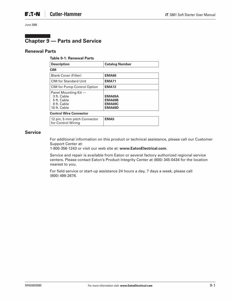
IT. S801 Soft Starter User Manual
MN03902008E For more information visit: www.EatonElectrical.com 9-1
June 2006
Chapter 9 — Parts and Service
Renewal Parts
Table 9-1: Renewal Parts
Service
For additional information on this product or technical assistance, please call our Customer Support Center at: 1-800-356-1243 or visit our web site at: www.EatonElectrical.com.
Service and repair is available from Eaton or several factory authorized regional service centers. Please contact Eaton’s Product Integrity Center at (800) 345-0434 for the location nearest to you.
For field service or start-up assistance 24 hours a day, 7 days a week, please call (800) 498-2678.
Description Catalog Number
CIM
Blank Cover (Filler) EMA68
CIM for Standard Unit EMA71
CIM for Pump Control Option EMA72
Panel Mounting Kit —3 ft. Cable5 ft. Cable8 ft. Cable
10 ft. Cable
EMA69AEMA69BEMA69CEMA69D
Control Wire Connector
12 pin, 5 mm pitch Connector for Control Wiring
EMA5

IT. S801 Soft Starter User Manual
9-2 For more information visit: www.EatonElectrical.com MN03902008E
June 2006

IT. S801 Soft Starter User Manual
MN03902008E For more information visit: www.EatonElectrical.com A-1
June 2006
Appendix A — Protection
Thermal Overload
The IT. Soft Starter features an electronic motor overload protection feature. This is intended to protect the motor and power wiring against overheating caused by excessive current for extended periods of time.
Note: Short circuit protection must be applied on the line side of the soft starter.
Entering the motor full load current rating, using the “FLA current adjust” dial programs trip current. It is programmable from 32% – 100% of the unit’s rated current.
Table A-1: Overload — Adjustment Settings
� See Application Notes, Appendix C.
Note: The “FLA current adjust” dial is settable to any point within its range.
Frame SizeCatalogNumber
FLA CurrentRange
N S801N37N3S 11 – 37
S801N66N3S 20 – 66
R S801R10N3S 32 – 105
S801R13N3S 42 – 135
T S801T18N3S 56 – 180
S801T18V3S
S801T24N3S 75 – 240
S801T24V3S
S801T30N3S 95 – 304
S801T30V3S
U S801U36N3S 112 – 360
S801U42N3S 131 – 420
S801U50N3S 156 – 500
V S801V36N3S 112 – 360
S801V36V3S
S801V42N3S 131 – 420
S801V42V3S
S801V50N3S 156 – 500
S801V50V3S
S801V65N3S 203 – 650
S801V65V3S
S801V72N3S 225 – 720
S801V72V3S
S801V85N3S 265 – 850
S801V85V3S
S801V10N3S � 320 – 1000

IT. S801 Soft Starter User Manual
A-2 For more information visit: www.EatonElectrical.com MN03902008E
June 2006
Overload Trip Curves
Figure A-1: Overload Trip Curves
Tim
e (
Se
co
nd
s)
Percent FLA
10000.0
1000.0
100.0
10.0
1.00
Class 5
Class 20
Class 10
Class 30
100 200 300 400 500 600 700 800 900
115%
Class 30
Class 10
Class 5
Class 20

IT. S801 Soft Starter User Manual
MN03902008E For more information visit: www.EatonElectrical.com A-3
June 2006
Thermal memory is incorporated to accurately monitor motor operating temperature. Ambient temperature does not affect soft starter function, within its operating limits.
The overload trip class can be set to class 5, 10, 20, or 30. The setting determines the time to trip, based on the severity of the overload condition.
Figure A-2: Setting Trip Class and FLA on the CIM
The normal overload trip setting may be disabled for the next start by placing the overload ON/DISABLE switch in the DISABLE position. This raises the overload fault trip point to 125% of the maximum current rating of the frame size. The overload trip resets to its normal set value for all subsequent starts. To affect another start, the ON/DISABLE switch would need to be moved to the ON position and then back into the DISABLE position. This same action is possible by momentarily connecting terminal 3 to the 24V DC + terminal prior to start. This only affects the next start and not any subsequent starts unless terminal 3 is again momentarily connected to the +24V DC prior to the start.
OVLDTRIP TRIP
CLASS
5
B
A
C
DFLA
10 20 30

IT. S801 Soft Starter User Manual
A-4 For more information visit: www.EatonElectrical.com MN03902008E
June 2006
Jam Detection
This feature is selectable: ON/DISABLE.
A current value of greater than 3 x FLA setting will stop the motor on a jam fault. If a jam is detected, the soft starter shuts down, and the “Jam” light illuminates.
Note: Jam detection is active only after the motor has reached full speed and is in bypass mode. If jam is disabled and the unit is in bypass and a jam occurs, the soft starter will trip on contactor overcurrent if the motor current exceeds 4x the starter maximum ampere rating.
Figure A-3: Jam Detection
Cu
rre
nt
Time
Unit Will Trip
Jam ProtectionSet at 300% ofIT. Soft StarterMotor FLASetting
Normal Operating Current
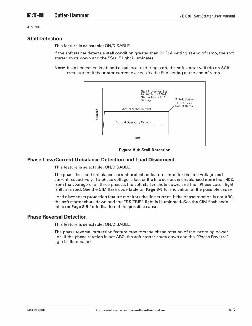
IT. S801 Soft Starter User Manual
MN03902008E For more information visit: www.EatonElectrical.com A-5
June 2006
Stall Detection
This feature is selectable: ON/DISABLE.
If the soft starter detects a stall condition greater than 2x FLA setting at end of ramp, the soft starter shuts down and the “Stall” light illuminates.
Note: If stall detection is off and a stall occurs during start, the soft starter will trip on SCR over current if the motor current exceeds 3x the FLA setting at the end of ramp.
Figure A-4: Stall Detection
Phase Loss/Current Unbalance Detection and Load Disconnect
This feature is selectable: ON/DISABLE.
The phase loss and unbalance current protection features monitor the line voltage and current respectively. If a phase voltage is lost or the line current is unbalanced more than 40% from the average of all three phases, the soft starter shuts down, and the “Phase Loss” light is illuminated. See the CIM flash code table on Page 8-5 for indication of the possible cause.
Load disconnect protection feature monitors the line current. If the phase rotation is not ABC, the soft starter shuts down and the “SS TRIP” light is illuminated. See the CIM flash code table on Page 8-5 for indication of the possible cause.
Phase Reversal Detection
This feature is selectable: ON/DISABLE.
The phase reversal protection feature monitors the phase rotation of the incoming power line. If the phase rotation is not ABC, the soft starter shuts down and the “Phase Reverse” light is illuminated.
Cu
rre
nt
Time
IT. Soft StarterWill Trip at
End of Ramp
Stall Protection Setfor 200% of IT. SoftStarter Motor FLASetting
Actual Motor Current
Normal Operating Current
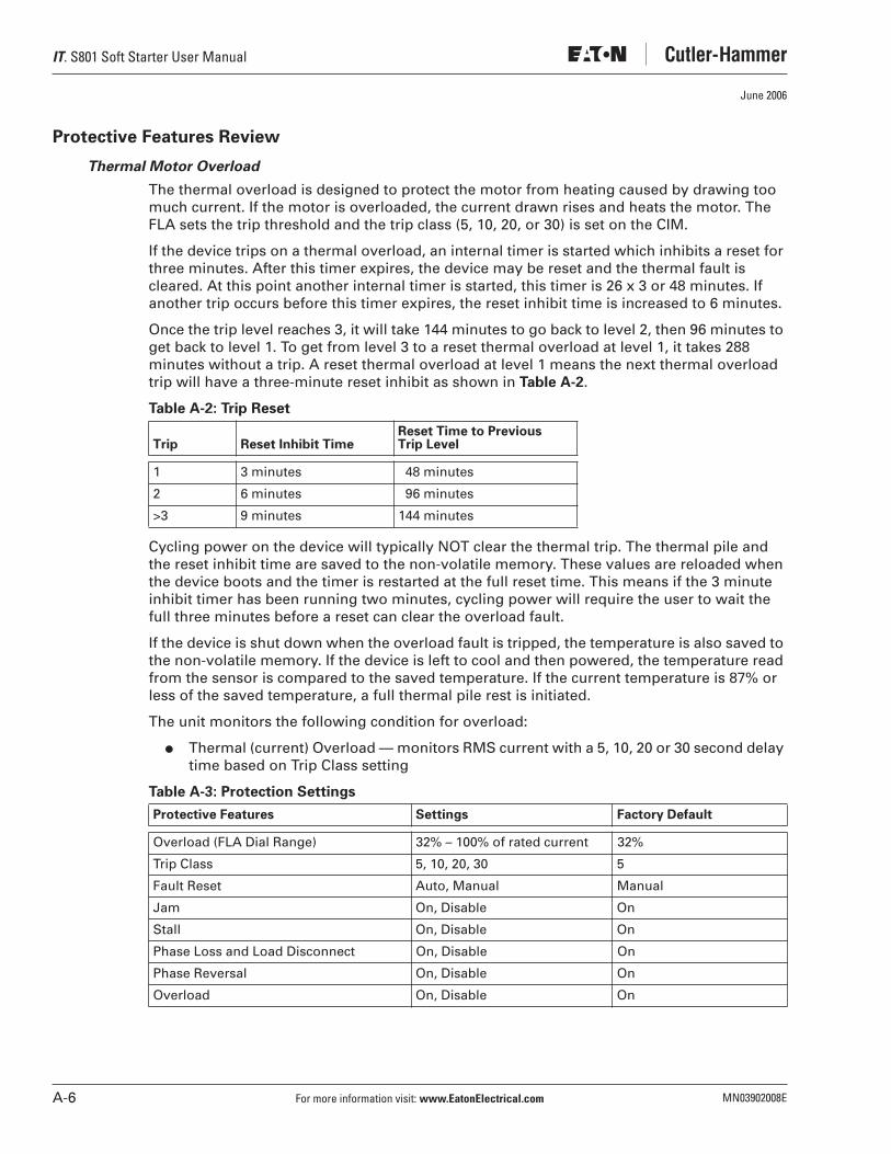
IT. S801 Soft Starter User Manual
A-6 For more information visit: www.EatonElectrical.com MN03902008E
June 2006
Protective Features Review
Thermal Motor Overload
The thermal overload is designed to protect the motor from heating caused by drawing too much current. If the motor is overloaded, the current drawn rises and heats the motor. The FLA sets the trip threshold and the trip class (5, 10, 20, or 30) is set on the CIM.
If the device trips on a thermal overload, an internal timer is started which inhibits a reset for three minutes. After this timer expires, the device may be reset and the thermal fault is cleared. At this point another internal timer is started, this timer is 26 x 3 or 48 minutes. If another trip occurs before this timer expires, the reset inhibit time is increased to 6 minutes.
Once the trip level reaches 3, it will take 144 minutes to go back to level 2, then 96 minutes to get back to level 1. To get from level 3 to a reset thermal overload at level 1, it takes 288 minutes without a trip. A reset thermal overload at level 1 means the next thermal overload trip will have a three-minute reset inhibit as shown in Table A-2.
Table A-2: Trip Reset
Cycling power on the device will typically NOT clear the thermal trip. The thermal pile and the reset inhibit time are saved to the non-volatile memory. These values are reloaded when the device boots and the timer is restarted at the full reset time. This means if the 3 minute inhibit timer has been running two minutes, cycling power will require the user to wait the full three minutes before a reset can clear the overload fault.
If the device is shut down when the overload fault is tripped, the temperature is also saved to the non-volatile memory. If the device is left to cool and then powered, the temperature read from the sensor is compared to the saved temperature. If the current temperature is 87% or less of the saved temperature, a full thermal pile rest is initiated.
The unit monitors the following condition for overload:
● Thermal (current) Overload — monitors RMS current with a 5, 10, 20 or 30 second delay time based on Trip Class setting
Table A-3: Protection Settings
Trip Reset Inhibit TimeReset Time to PreviousTrip Level
1 3 minutes 48 minutes
2 6 minutes 96 minutes
>3 9 minutes 144 minutes
Protective Features Settings Factory Default
Overload (FLA Dial Range) 32% – 100% of rated current 32%
Trip Class 5, 10, 20, 30 5
Fault Reset Auto, Manual Manual
Jam On, Disable On
Stall On, Disable On
Phase Loss and Load Disconnect On, Disable On
Phase Reversal On, Disable On
Overload On, Disable On

IT. S801 Soft Starter User Manual
MN03902008E For more information visit: www.EatonElectrical.com B-1
June 2006
Appendix B — Ratings, Cooling and Power Losses
Horsepower and kW Ratings
Standard Duty Ratings
Table B-1: 15 Second Ramp, 4 Starts per Hour, 300% Current Limit @ 40°C
� Definite purpose rating of 4 starts per hour (1 every 15 minutes), 15 sec. ramp, 300% curent limit @ 40°C. See Severe Duty ratings on Page B-7, if parameters are exceeded.
� See Application Notes, Appendix C.
Max.Current
Three-Phase Motors
Catalog Number
kW Rating (50 Hz) hp Rating (60 Hz)
230V380 – 400V 440V
200V 230V 460V 575 – 690V
1.0SF 1.15SF 1.0SF 1.15SF 1.0SF 1.15SF 1.0SF 1.15SF
Frame Size N
37 10 18.5 18.5 10 10 10 10 25 20 30 30 S801N37N3S
66 18.5 30 37 20 15 20 20 50 40 60 50 S801N66N3S
Frame Size R
105 30 55 59 30 25 40 30 75 60 100 75 S801R10N3S
135 40 63 80 40 30 50 40 100 75 125 100 S801R13N3S
Frame Size T
180 51 90 110 60 50 60 60 150 125 150 150 S801T18N3S
S801T18V3S
240 75 110 147 75 60 75 75 200 150 200 200 S801T24N3S
S801T24V3S
304 90 160 185 100 75 100 100 250 200 300 250 S801T30N3S
S801T30V3S
Frame Size U
360 110 185 220 125 100 150 125 300 250 350 300 S801U36N3S
420 129 220 257 150 125 175 150 350 300 450 350 S801U42N3S
500 150 257 300 150 150 200 150 400 350 500 450 S801U50N3S �
Frame Size V
360 110 185 220 125 100 150 125 300 250 350 300 S801V36N3S
420 129 220 257 150 125 175 150 350 300 450 350 S801V42N3S
500 150 257 300 150 150 200 150 400 350 500 450 S801V50N3S
650 200 355 425 250 200 250 200 500 450 600 500 S801V65N3S
S801V65V3S
720 220 400 450 — — 300 250 600 500 700 600 S801V72N3S
S801V72V3S
850 257 475 500 — — 350 300 700 600 900 700 S801V85N3S
S801V85V3S
1000 277 525 50 — — 400 350 800 700 900 800 S801V10N3S �

IT. S801 Soft Starter User Manual
B-2 For more information visit: www.EatonElectrical.com MN03902008E
June 2006
Table B-2: 25 Second Ramp, 4 Starts per Hour, 300% Current Limit @ 40°C
� See Application Notes, Appendix C.
Max.Current
Three-Phase Motors
Catalog Number
kW Rating (50 Hz) hp Rating (60 Hz)
230V380 – 400V 440V
200V 230V 460V 575 – 690V
1.0SF 1.15SF 1.0SF 1.15SF 1.0SF 1.15SF 1.0SF 1.15SF
Frame Size N
34 9 15 18.5 10 7-1/2 10 10 25 20 30 25 S801N37N3S
63 15 30 33 20 15 20 20 40 40 60 50 S801N66N3S
Frame Size R
96 25 45 55 30 25 30 30 75 60 75 75 S801R10N3S
120 33 63 63 40 30 40 40 75 75 100 100 S801R13N3S
Frame Size T
150 45 80 90 50 40 50 50 100 100 150 125 S801T18N3S
S801T18V3S
215 63 110 132 60 60 75 60 150 150 200 150 S801T24N3S
S801T24V3S
278 80 147 160 75 75 100 75 200 200 250 250 S801T30N3S
S801T30V3S
Frame Size U
320 90 160 185 100 75 125 100 250 200 300 250 S801U36N3S
380 110 200 220 125 100 150 125 300 250 350 300 S801U42N3S
460 140 250 280 150 125 150 150 350 300 450 400 S801U50N3S
Frame Size V
320 90 160 185 100 75 125 100 250 200 300 250 S801V36N3S
380 110 200 220 125 100 150 125 300 250 350 300 S801V42N3S
460 140 250 280 150 125 150 150 350 300 450 400 S801V50N3S
610 185 315 375 250 150 200 200 500 450 600 500 S801V65N3S
S801V65V3S
680 200 375 445 — 200 250 200 600 500 700 600 S801V72N3S
S801V72V3S
810 250 450 500 — — 300 300 700 600 900 700 S801V85N3S
S801V85V3S
890 290 510 560 — — 400 350 700 600 900 700 S801V10N3S �

IT. S801 Soft Starter User Manual
MN03902008E For more information visit: www.EatonElectrical.com B-3
June 2006
Table B-3: 15 Second Ramp, 4 Starts per Hour, 300% Current Limit @ 50°C
� See Application Notes, Appendix C.
Max.Current
Three-Phase Motors
Catalog Number
kW Rating (50 Hz) hp Rating (60 Hz)
230V380 – 400V 440V
200V 230V 460V 575 – 690V
1.0SF 1.15SF 1.0SF 1.15SF 1.0SF 1.15SF 1.0SF 1.15SF
Frame Size N
34 9 15 18.5 10 7-1/2 10 10 25 20 30 25 S801N37N3S
63 15 30 33 20 15 20 20 40 40 60 50 S801N66N3S
Frame Size R
96 25 45 55 30 25 30 30 75 60 75 75 S801R10N3S
120 33 63 63 40 30 40 40 75 75 100 100 S801R13N3S
Frame Size T
150 45 80 90 50 40 50 50 100 100 150 125 S801T18N3S
S801T18V3S
215 63 110 132 60 60 75 60 150 150 200 150 S801T24N3S
S801T24V3S
278 80 147 160 75 75 100 75 200 200 250 250 S801T30N3S
S801T30V3S
Frame Size U
320 90 160 185 100 75 125 100 250 200 300 250 S801U36N3S
380 110 200 220 125 100 150 125 300 250 350 300 S801U42N3S
460 140 250 280 150 125 150 150 350 300 450 400 S801U50N3S
Frame Size V
320 90 160 185 100 75 125 100 250 200 300 250 S801V36N3S
380 110 200 220 125 100 150 125 300 250 350 300 S801V42N3S
460 140 250 280 150 125 150 150 350 300 450 400 S801V50N3S
610 185 315 375 250 150 200 200 500 450 600 500 S801V65N3S
S801V65V3S
680 200 375 445 — 200 250 200 600 500 700 600 S801V72N3S
S801V72V3S
830 257 450 500 — — 300 300 700 600 900 700 S801V85N3S
S801V85V3S
960 302 510 540 — — 350 300 800 700 900 800 S801V10N3S �

IT. S801 Soft Starter User Manual
B-4 For more information visit: www.EatonElectrical.com MN03902008E
June 2006
Table B-4: 50 Second Ramp, 2 Starts per Hour, 300% Current Limit @ 50°C
� See Application Notes, Appendix C.
Max.Current
Three-Phase Motors
Catalog Number
kW Rating (50 Hz) hp Rating (60 Hz)
230V380 – 400V 440V
200V 230V 460V 575 – 690V
1.0SF 1.15SF 1.0SF 1.15SF 1.0SF 1.15SF 1.0SF 1.15SF
Frame Size N
21 5.5 10 11 5 5 5 5 15 10 15 15 S801N37N3S
42 11 18.5 22 10 10 15 10 30 25 40 30 S801N66N3S
Frame Size R
60 15 30 33 15 15 20 15 40 40 50 50 S801R10N3S
80 22 40 45 25 20 30 25 60 50 75 60 S801R13N3S
Frame Size T
115 33 59 63 30 30 40 30 75 75 100 100 S801T18N3S
S801T18V3S
150 45 80 90 50 40 50 50 100 100 150 125 S801T24N3S
S801T24V3S
192 55 100 110 60 50 60 60 150 125 200 150 S801T30N3S
S801T30V3S
Frame Size U
280 80 150 160 75 75 100 75 200 200 250 250 S801U36N3S
340 110 180 200 100 100 125 100 250 200 350 300 S801U42N3S
380 110 200 220 125 100 150 125 300 250 350 300 S801U50N3S
Frame Size V
280 80 150 160 75 75 100 75 200 200 250 250 S801V36N3S
340 110 180 200 100 100 125 100 250 200 350 300 S801V42N3S
380 110 200 220 125 100 150 125 300 250 350 300 S801V50N3S
420 129 220 257 150 125 150 150 350 300 450 350 S801V65N3S
S801V65V3S
480 147 257 295 150 150 200 150 400 350 500 450 S801V72N3S
S801V72V3S
590 180 315 375 200 150 200 200 500 400 600 500 S801V85N3S
S801V85V3S
650 205 370 415 250 200 250 200 500 450 600 500 S801V10N3S �

IT. S801 Soft Starter User Manual
MN03902008E For more information visit: www.EatonElectrical.com B-5
June 2006
Table B-5: 15 Second Ramp, 4 Starts per Hour, 450% Current Limit @ 40°C
� See Application Notes, Appendix C.
Max.Current
Three-Phase Motors
Catalog Number
kW Rating (50 Hz) hp Rating (60 Hz)
230V380 – 400V 440V
200V 230V 460V 575 – 690V
1.0SF 1.15SF 1.0SF 1.15SF 1.0SF 1.15SF 1.0SF 1.15SF
Frame Size N
29 7.5 12.5 15 7-1/2 7-1/2 10 7-1/2 20 15 25 20 S801N37N3S
49 12.5 22 25 15 10 15 15 30 30 40 40 S801N66N3S
Frame Size R
73 18.5 37 40 20 20 25 20 50 40 60 60 S801R10N3S
94 25 45 55 30 25 30 30 60 60 75 75 S801R13N3S
Frame Size T
155 45 80 90 50 40 60 50 100 100 150 125 S801T18N3S
S801T18V3S
219 63 110 132 60 60 75 60 150 150 200 150 S801T24N3S
S801T24V3S
280 80 150 160 75 75 100 75 200 200 250 250 S801T30N3S
S801T30V3S
Frame Size U
345 100 185 200 100 100 125 100 250 200 350 300 S801U36N3S
405 110 200 250 125 100 150 125 300 250 400 350 S801U42N3S
Frame Size V
345 100 185 200 100 100 125 100 250 200 350 300 S801V36N3S
405 110 200 250 125 100 150 125 300 250 400 350 S801V42N3S
465 140 250 280 150 125 150 150 350 300 450 400 S801V50N3S
S801V50V3S
530 160 280 335 150 150 200 150 450 350 500 450 S801V65N3S
S801V65V3S
590 180 315 375 200 150 — 200 500 400 600 500 S801V72N3S
S801V72V3S
651 200 355 425 — — — — 600 450 700 600 S801V85N3S
S801V85V3S
754 220 400 465 — — — — 600 500 800 700 S801V10N3S �
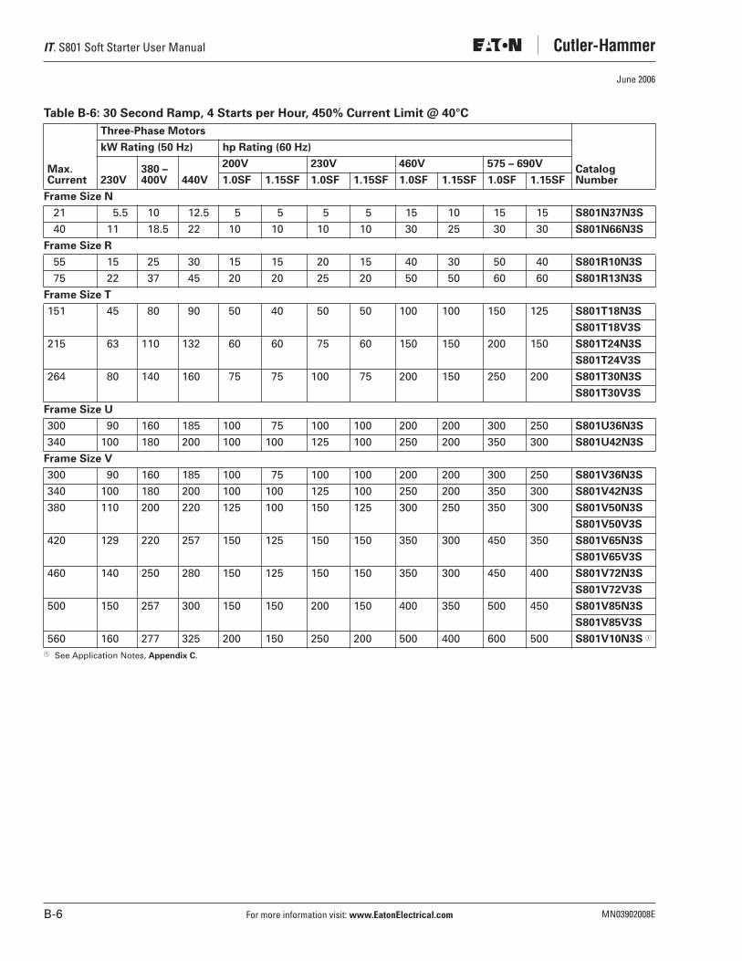
IT. S801 Soft Starter User Manual
B-6 For more information visit: www.EatonElectrical.com MN03902008E
June 2006
Table B-6: 30 Second Ramp, 4 Starts per Hour, 450% Current Limit @ 40°C
� See Application Notes, Appendix C.
Max.Current
Three-Phase Motors
Catalog Number
kW Rating (50 Hz) hp Rating (60 Hz)
230V380 – 400V 440V
200V 230V 460V 575 – 690V
1.0SF 1.15SF 1.0SF 1.15SF 1.0SF 1.15SF 1.0SF 1.15SF
Frame Size N
21 5.5 10 12.5 5 5 5 5 15 10 15 15 S801N37N3S
40 11 18.5 22 10 10 10 10 30 25 30 30 S801N66N3S
Frame Size R
55 15 25 30 15 15 20 15 40 30 50 40 S801R10N3S
75 22 37 45 20 20 25 20 50 50 60 60 S801R13N3S
Frame Size T
151 45 80 90 50 40 50 50 100 100 150 125 S801T18N3S
S801T18V3S
215 63 110 132 60 60 75 60 150 150 200 150 S801T24N3S
S801T24V3S
264 80 140 160 75 75 100 75 200 150 250 200 S801T30N3S
S801T30V3S
Frame Size U
300 90 160 185 100 75 100 100 200 200 300 250 S801U36N3S
340 100 180 200 100 100 125 100 250 200 350 300 S801U42N3S
Frame Size V
300 90 160 185 100 75 100 100 200 200 300 250 S801V36N3S
340 100 180 200 100 100 125 100 250 200 350 300 S801V42N3S
380 110 200 220 125 100 150 125 300 250 350 300 S801V50N3S
S801V50V3S
420 129 220 257 150 125 150 150 350 300 450 350 S801V65N3S
S801V65V3S
460 140 250 280 150 125 150 150 350 300 450 400 S801V72N3S
S801V72V3S
500 150 257 300 150 150 200 150 400 350 500 450 S801V85N3S
S801V85V3S
560 160 277 325 200 150 250 200 500 400 600 500 S801V10N3S �
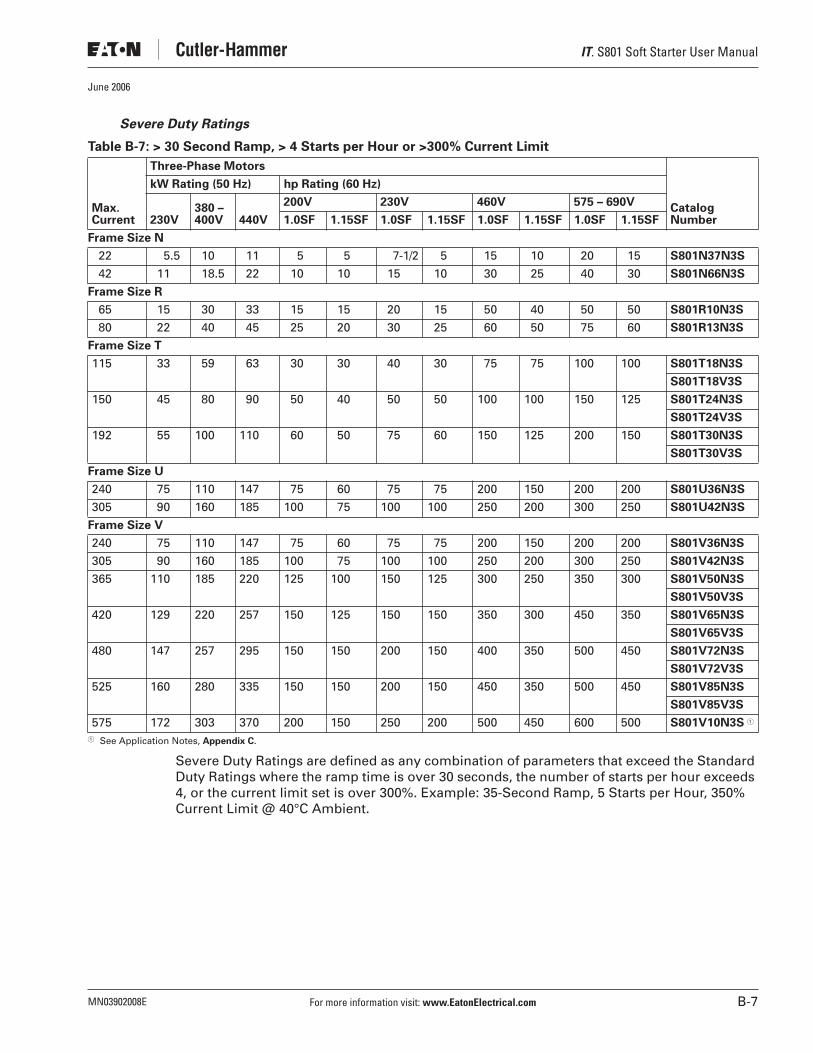
IT. S801 Soft Starter User Manual
MN03902008E For more information visit: www.EatonElectrical.com B-7
June 2006
Severe Duty Ratings
Table B-7: > 30 Second Ramp, > 4 Starts per Hour or >300% Current Limit
� See Application Notes, Appendix C.
Severe Duty Ratings are defined as any combination of parameters that exceed the Standard Duty Ratings where the ramp time is over 30 seconds, the number of starts per hour exceeds 4, or the current limit set is over 300%. Example: 35-Second Ramp, 5 Starts per Hour, 350% Current Limit @ 40°C Ambient.
Max.Current
Three-Phase Motors
Catalog Number
kW Rating (50 Hz) hp Rating (60 Hz)
230V380 – 400V 440V
200V 230V 460V 575 – 690V
1.0SF 1.15SF 1.0SF 1.15SF 1.0SF 1.15SF 1.0SF 1.15SF
Frame Size N
22 5.5 10 11 5 5 7-1/2 5 15 10 20 15 S801N37N3S
42 11 18.5 22 10 10 15 10 30 25 40 30 S801N66N3S
Frame Size R
65 15 30 33 15 15 20 15 50 40 50 50 S801R10N3S
80 22 40 45 25 20 30 25 60 50 75 60 S801R13N3S
Frame Size T
115 33 59 63 30 30 40 30 75 75 100 100 S801T18N3S
S801T18V3S
150 45 80 90 50 40 50 50 100 100 150 125 S801T24N3S
S801T24V3S
192 55 100 110 60 50 75 60 150 125 200 150 S801T30N3S
S801T30V3S
Frame Size U
240 75 110 147 75 60 75 75 200 150 200 200 S801U36N3S
305 90 160 185 100 75 100 100 250 200 300 250 S801U42N3S
Frame Size V
240 75 110 147 75 60 75 75 200 150 200 200 S801V36N3S
305 90 160 185 100 75 100 100 250 200 300 250 S801V42N3S
365 110 185 220 125 100 150 125 300 250 350 300 S801V50N3S
S801V50V3S
420 129 220 257 150 125 150 150 350 300 450 350 S801V65N3S
S801V65V3S
480 147 257 295 150 150 200 150 400 350 500 450 S801V72N3S
S801V72V3S
525 160 280 335 150 150 200 150 450 350 500 450 S801V85N3S
S801V85V3S
575 172 303 370 200 150 250 200 500 450 600 500 S801V10N3S �

IT. S801 Soft Starter User Manual
B-8 For more information visit: www.EatonElectrical.com MN03902008E
June 2006
Cooling
Microcontroller controlled fans are used to cool the IT. Soft Starter. The fans are turned on when the temperature of any of the thermal sensors exceeds preset value. Once the fans are started, they will not go off until the temperature goes below the off set point for 10 minutes.
The fans will also be turned on whenever the IT. is started, stopped or jogged. The fans will remain on for 10 minutes to assure the SCRs are adequately cooled prior to the next start.
If a temperature is sensed above a second preset level, a Pole Over-Temperature Fault will occur. This fault cannot be reset until the temperature returns to a safe level.
Note: The fans will only operate if 24V DC is applied to the + and – terminals. Cycling power during the 10 minute timeout after a start, stop or jog will reset the fans to off.
Power Losses
The following table lists the maximum power loss for each IT. Soft Starter when it is operating in the across-the-line mode with its bypass contactor pulled in. These losses should be used in conjunction with the losses of another cabinet mounted device to determine the enclosure size and any cooling requirements.
Table B-8: Maximum Power Loss
Frame Size
CatalogNumber
CurrentRange
Across-the-Line-Losses (Watts)
N S801N37N3S 11 – 37 30
S801N66N3S 20 – 66 33
R S801R10N3S 32 – 105 47
S801R13N3S 42 – 135 55
T S801T18N3S 56 – 180 37
S801T18V3S
S801T24N3S 75 – 240 40
S801T24V3S
S801T30N3S 95 – 304 45
S801T30V3S
U S801U36N3S 112 – 360 76
S801U42N35 131 – 420 92
S801U50N3S 156 – 500 116
V S801V36N3S 112 – 360 56
S801V36V3S
S801V42N3S 131 – 420 64
S801V42V3S
S801V50N3S 156 – 500 78
S801V50V3S
S801V65N3S 203 – 650 109
S801V65V3S
S801V72N3S 225 – 720 127
S801V72V3S
S801V85N3S 265 – 850 164
S801V85V3S
S801V10N3S 310 – 1000 215

IT. S801 Soft Starter User Manual
MN03902008E For more information visit: www.EatonElectrical.com C-1
June 2006
Appendix C — Motor/Application Considerations
Using MOVs
Most utility power systems experience periodic transient voltages. Line or power factor correction capacitor switching, nearby lightning strikes, utility supply faults, or a user starting or shutting down a large load such as a motor can cause these voltages. The IT. Soft Starter has been designed to handle transient voltages of up to 4 kV lasting up to 20 µS.
If transient voltages of greater magnitude or longer duration than the standard withstand capability are expected, a protective module must be installed. The protective module contains metal oxide varistors (MOVs). MOVs are devices that remain in a passive state until a transient voltage occurs. Under the transient condition, the MOV turns on and holds the peak line voltage down to a level less than the IT. transient voltage rating. When the transient clears, the MOV returns to a passive state.
Eaton offers two MOV option kits:
Table C-1: MOV Kit Options
The EMS38 is panel mounted, while the EMS39 and EMS41 are mounted directly on the IT. Soft Starter.
In situations where an MOV must be used, the installer may choose to apply a different transient absorption device, but it must be equivalent to the EMS38, EMS39 or EMS41. These MOVs may also be used on the load side of the soft starter where long cables connect the motor to the soft starter or where the cables are located outdoors.
Squirrel Cage Motor
This is the most common application.
The motor is configured with three motor leads available.
In this case, wire the motor to the soft starter with one lead per phase, observing proper phase rotation. An in-sight disconnect means should be installed, per code requirements.
CatalogNumber Description
EMS38 600V (max) MOV for S801N and S801R Soft Start (side mounted)
EMS39 600V (max) MOV for S801T, S801U and S801V Soft Start
EMS41 690V (max) MOV for S801T, V35 and S801V, V35

IT. S801 Soft Starter User Manual
C-2 For more information visit: www.EatonElectrical.com MN03902008E
June 2006
Wye-Delta Motor
The wye-delta motor is a traditional way of achieving a reduced voltage start using regular contactors and starters. In this method, the motor is constructed with all six leads brought out to connect the unit in a wye configuration. This allows about 58% of the current (33% starting torque) to be applied during start-up. A timer is used to control the circuit and switch to the delta configuration as the unit approaches full speed.
In this case, wire the six-lead motor in a standard delta configuration. The soft starter is then used to control the voltage and motor torque without the need for additional circuitry. An in-sight disconnect means should be installed, per local code. The IT. Soft Starter must be wired into the three-phase line feeding the three main motor input leads as would be done for normal across-the-line starting. It must not be wired internally between motor windings in
an inside-the-delta configuration. If an inside-the-delta starting configuration is desired,
please contact Eaton for details about our inside-the-delta soft starters, designated
S801**D.
Part Winding Motor
The part winding motor is another design created to help achieve a soft start to the load. A part winding motor is constructed of two separate (but parallel) windings. When using a traditional starter, the first winding would receive full voltage. This winding supplies as much as 400% of the motors FLA; about 45% starting torque in a delta configuration for motor start-up. After a timed delay, full voltage is applied to the second winding. The second winding acts in parallel with the first to provide for normal running current. Part winding motors are available in both a wye and delta configuration, dependent upon the manufacturer. Refer to the motor nameplate for the correct wiring information. In this case, wire the two windings in parallel. The soft starter is then used to control the current applied to the motor. An in-sight disconnect means should be installed, per code requirements.
Dual Voltage Motor
A dual voltage motor should be wired into the appropriate configuration for the line voltage it is being applied to. Refer to the motor nameplate for the correct wiring information. The soft starter must be selected for the appropriate line voltage.
Multi-Speed Motor
Some motors have multiple windings to allow operation at different base speeds. The multiple speeds are sometimes utilized for soft starting and other times for a process requirement of the machine to which it is attached. If only one speed is required, the motor should be wired for that speed. If multiple speeds are required, the appropriate contactors will need to be connected to the output of the soft starter. The contactors must be in the selected speed position before the soft starter is started. The motor must be stopped and the soft starter turned off before the speed selection contactors are changed.

IT. S801 Soft Starter User Manual
MN03902008E For more information visit: www.EatonElectrical.com C-3
June 2006
Other Winding Configurations
Motors with other winding configurations, designed for specific characteristics, should be wired in a fashion consistent with their intended use. The motor nameplate contains information on the available configurations. The motor winding configuration chosen must be appropriate for the available line voltage. The soft starter must also be selected on the basis of the configuration chosen.
Power Factor Correction Capacitors
Power factor correction capacitors should be installed on the line side of the soft starter. It is recommended that at least 10 feet of cable be between the capacitor and the soft starter. The power factor correction capacitors can be switched with a separate contactor. NEMA ICS2-1988 Part 2-210.81.01 provides recommendations for when a separate contactor should be used to switch the power factor correction capacitor including high inertia loads, reversing motors, frequently jogged motors and multi-speed motors.
It is not recommended that the power factor correction capacitors be used on the load side of the soft starter. If used on the load side, the overload relay will measure the combination of capacitor and motor current causing the overload relay to not function correctly.
Never megger a motor while it is connected to the IT. Soft Starter. Disconnect the leads at the IT. Soft Starter before meggering the motor.
Ne jamais régler un moteur alors qu’il est branché au démarreur progressif IT. Débrancher les fils au démarreur progressif IT. Avant de régler le moteur.
Nunca efectúe pruebas del motor con un megóhmetro mientras esté conectado al arrancador Soft Starter IT. Desconecte los cables en el arrancador IT. antes de usar el megóhmetro.
Caution! Attention! Precaución!

IT. S801 Soft Starter User Manual
C-4 For more information visit: www.EatonElectrical.com MN03902008E
June 2006

IT. S801 Soft Starter User Manual
MN03902008E For more information visit: www.EatonElectrical.com D-1
June 2006
Appendix D — Special Function Options
This section covers the descriptions, identification, installation and setup of factory-installed options that are not provided with the standard S801 soft starter.
Pump Control Option
This option is intended to reduce the potential for water hammer in a centrifugal pump system by utilizing a starting and stopping algorithm developed for pump control. Upon a start command, the speed of the motor is increased, under the control of the IT. Soft Starter microprocessor, to achieve a gentle start. After the speed has reached its nominal value, the bypass contactors close and the pump operates as with any other starter. Upon a stop command, the bypass contactors are opened and the motor speed is decreased in a tapered manner, to gradually slow the flow until the motor is brought to a stop. The start and stop ramp times are user adjustable and are to be set for the application requirements.
The pump control option is a factory installed feature. Factory installed options are designated by the eighth character in the catalog number. Unmodified IT. Soft Starters have an N as their eighth character. IT. Soft Starters with the pump control option have a P as their eighth character, as in S801XXXP3S.
Installation
Install and wire your IT. Soft Starter per the instructions found in the beginning of this manual.
Setup
The pump control option is enabled by the S. F. — ENABLE/DISABLE DIP switch located on the control interface module (CIM). To enable this feature, position this switch in the ENABLE position. When the pump control is enabled, the RAMP START/CURRENT LIMIT DIP switch is disabled. The default becomes RAMP START. See Figure D-1.
Figure D-1: IT. Soft Starter CIM
TORQUE (%)
T2T1
T1
T1TORQUE (T2)
TORQUE (T2)
45
5 85
652545
5 85
6525
30
0 60
TIME (Sec.)
t k0 2
RAMP START
MANUAL RESET
JAMSTALL
PH. REV.PH. LOSS
ONONONON
DISABLEDISABLEDISABLEAUTO RESET
CURRENT LIMIT
DISABLE
START
Made in U.S.A.
ON DISABLEOVERLOAD -
20
0.5
EMA72S.S. TRIP
60 15 45
5 10 20 30
BYPASS
BYPASS
t r t s
t k t r t s
t k t r t s
10
1
1.50.5
180
4015
1205
OVLDTRIP TRIP
CLASS
B
A
C
DFLA
S.F. - ENABLE DISABLE

IT. S801 Soft Starter User Manual
D-2 For more information visit: www.EatonElectrical.com MN03902008E
June 2006
Adjustment
All of the adjustments to the IT. Soft Starter are made as noted in the user manual. The major difference between the standard IT. Soft Starter and one with the pump start option is the special algorithm for gentle start and stop with centrifugal flow loads to minimize the potential for water hammer.
Tr, located on the CIM adjusts the start ramp. It has a range of 0.5 to 180 seconds. The factory default is 9 seconds. The soft stop time is adjusted by ts, which has a range of 0.0 to 120 seconds (multiply the scale value for ts by 2 to determine the actual time setting), with the factory default being 0.0 seconds. These adjustments are application dependent, and should be made to minimize any surge or water hammer effects. Typically ts would not be set short, since the stop might not differ much from a coast-to-stop. The soft stop time adjustment may often be in the range of 30 to 40 seconds, but needs to be set appropriately for the system requirements. If reduction or elimination of water hammer is not achieved, it may be necessary to lengthen ts to achieve the desired result. Note that long stop times will result in greater motor heating than shorter stop times. This can affect the number of start/stop cycles allowed per hour due to the IT. Soft Starter or motor thermal limits.
Figure D-2: Pump Start Ramp and Soft Pump Stop
The tr adjustment is tapered to provide for easier setting of both long and short times. The first half of the control adjusts from 0.5 to 20 seconds, the next quarter from 20 to 60 seconds, and the last quarter from 60 to 180 seconds. The ts adjustment is linear with a time scale twice that shown in the CIM.
Extended Ramp Option
This option allows for a longer ramp acceleration time of 0.5 to 360 seconds. The Extended Ramp option is a factory-installed option designated by the tenth character in the Catalog Number. Standard Ramp S801 IT. Soft Starters have an S as their tenth character. S801 IT. Soft Starters with the Extended Ramp option have an L as their tenth character, as in S801XXXX3L. Note that long ramp times will result in greater motor heating than shorter ramp times. This can affect the number of start/stop cycles allowed per hour due to the IT. Soft Starter or motor thermal limits.
Installation
Install and wire your IT. Soft Starter per the instructions found in the beginning of this manual.
Setup
Set up the soft starter per the instructions found in Chapter 7 of this manual.
100%
tr
Start Soft Pump Stop
Sp
ee
d
Time (Seconds)
ts
Run
Coast to Stop


Eaton Electrical Inc.1000 Cherrington ParkwayMoon Township, PA 15108-4312USAtel: 1-800-525-2000www.EatonElectrical.com
© 2006 Eaton CorporationAll Rights ReservedPrinted in USAPublication No. MN03902008E/CPGJune 2006
Company InformationEaton’s electrical business is a global leader in electrical control, power distribution, and industrial automation products and services. Through advanced product development, world-class manufacturing methods, and global engineering services and support, Eaton’s electrical business provides customer-driven solutions under brand names such as Cutler-Hammer®, Powerware®, Durant®, Heinemann®, Holec® and MEM®, which globally serve the changing needs of the industrial, utility, light commercial, residential, and OEM markets. For more information, visit www.EatonElectrical.com.
Eaton Corporation is a diversified industrial manufacturer with 2005 sales of $11.1 billion. Eaton is a global leader in electrical systems and components for power quality, distribution and control; fluid power systems and services for industrial, mobile and aircraft equipment; intelligent truck drivetrain systems for safety and fuel economy; and automotive engine air management systems, powertrain solutions and specialty controls for performance, fuel economy and safety. Eaton has 60,000 employees and sells products to customers in more than 125 countries. For more information, visit www.eaton.com.