item #0293809 blower accessory - the home … #0293809 blower accessory questions, problems, missing...
TRANSCRIPT
ITEM#0293809
BLOWER ACCESSORY
Questions, problems, missing parts?Beforereturningtoyourretailer,callourcustomerservicedepartmentat1-877-886-5989,8:00a.m-4:30p.m.,EST,[email protected].
PC-FANQEB-1104
MODEL#QEB100Españolp.35
2
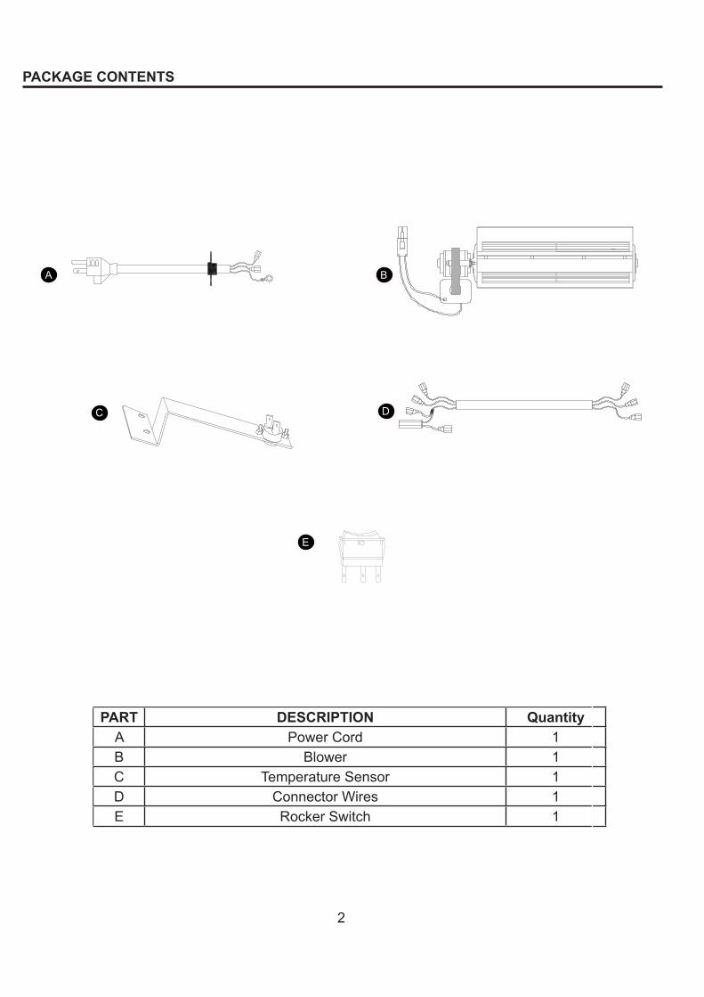
PART DESCRIPTION QuantityA PowerCord 1B Blower 1C TemperatureSensor 1D ConnectorWires 1E RockerSwitch 1
PACKAGE CONTENTS
A
C
B
D
E
3
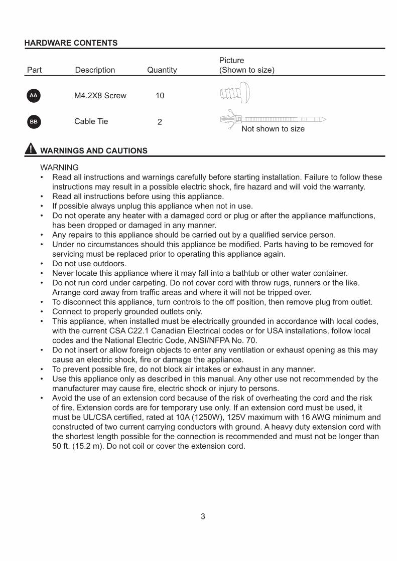
HARDWARE CONTENTS
AA
2
10
CableTie
M4.2X8Screw
WARNINGS AND CAUTIONS
WARNING• Readallinstructionsandwarningscarefullybeforestartinginstallation.Failuretofollowthese
instructionsmayresultinapossibleelectricshock,firehazardandwillvoidthewarranty.• Readallinstructionsbeforeusingthisappliance.• Ifpossiblealwaysunplugthisappliancewhennotinuse.• Donotoperateanyheaterwithadamagedcordorplugoraftertheappliancemalfunctions,
hasbeendroppedordamagedinanymanner.• Anyrepairstothisapplianceshouldbecarriedoutbyaqualifiedserviceperson.• Undernocircumstancesshouldthisappliancebemodified.Partshavingtoberemovedfor
servicingmustbereplacedpriortooperatingthisapplianceagain.• Donotuseoutdoors.• Neverlocatethisappliancewhereitmayfallintoabathtuborotherwatercontainer.• Donotruncordundercarpeting.Donotcovercordwiththrowrugs,runnersorthelike.
Arrangecordawayfromtrafficareasandwhereitwillnotbetrippedover.• Todisconnectthisappliance,turncontrolstotheoffposition,thenremoveplugfromoutlet.• Connecttoproperlygroundedoutletsonly.• Thisappliance,wheninstalledmustbeelectricallygroundedinaccordancewithlocalcodes,
withthecurrentCSAC22.1CanadianElectricalcodesorforUSAinstallations,followlocalcodesandtheNationalElectricCode,ANSI/NFPANo.70.
• Donotinsertorallowforeignobjectstoenteranyventilationorexhaustopeningasthismaycauseanelectricshock,fireordamagetheappliance.
• Topreventpossiblefire,donotblockairintakesorexhaustinanymanner.• Usethisapplianceonlyasdescribedinthismanual.Anyotherusenotrecommendedbythe
manufacturermaycausefire,electricshockorinjurytopersons.• Avoidtheuseofanextensioncordbecauseoftheriskofoverheatingthecordandtherisk
offire.Extensioncordsarefortemporaryuseonly.Ifanextensioncordmustbeused,itmustbeUL/CSAcertified,ratedat10A(1250W),125Vmaximumwith16AWGminimumandconstructedoftwocurrentcarryingconductorswithground.Aheavydutyextensioncordwiththeshortestlengthpossiblefortheconnectionisrecommendedandmustnotbelongerthan50ft.(15.2m).Donotcoilorcovertheextensioncord.
BB
PicturePart Description Quantity (Showntosize)
Notshowntosize
4
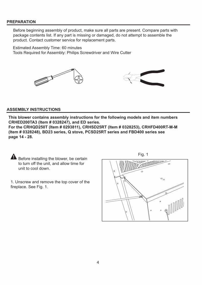
Fig.1
ASSEMBLY INSTRUCTIONS
PREPARATION
Beforebeginningassemblyofproduct,makesureallpartsarepresent.Comparepartswithpackagecontentslist.Ifanypartismissingordamaged,donotattempttoassembletheproduct.Contactcustomerserviceforreplacementparts.
EstimatedAssemblyTime:60minutesToolsRequiredforAssembly:PhilipsScrewdriverandWireCutter
1.Unscrewandremovethetopcoverofthefireplace.SeeFig.1.
Beforeinstallingtheblower,becertaintoturnofftheunit,andallowtimeforunittocooldown.
This blower contains assembly instructions for the following models and item numbers CRHED200TA3 (Item # 0328247), and ED series.For the CRHQD250T (Item # 0293811), CRHSD25RT (Item # 0328253), CRHFD400RT-M-M (Item # 0328248), BD23 series, Q stove, PCSD25RT series and FBD400 series see page 14 - 28.
5
Hardware Used
M4.2X8screw x3AA
Fig.2
Fig.3
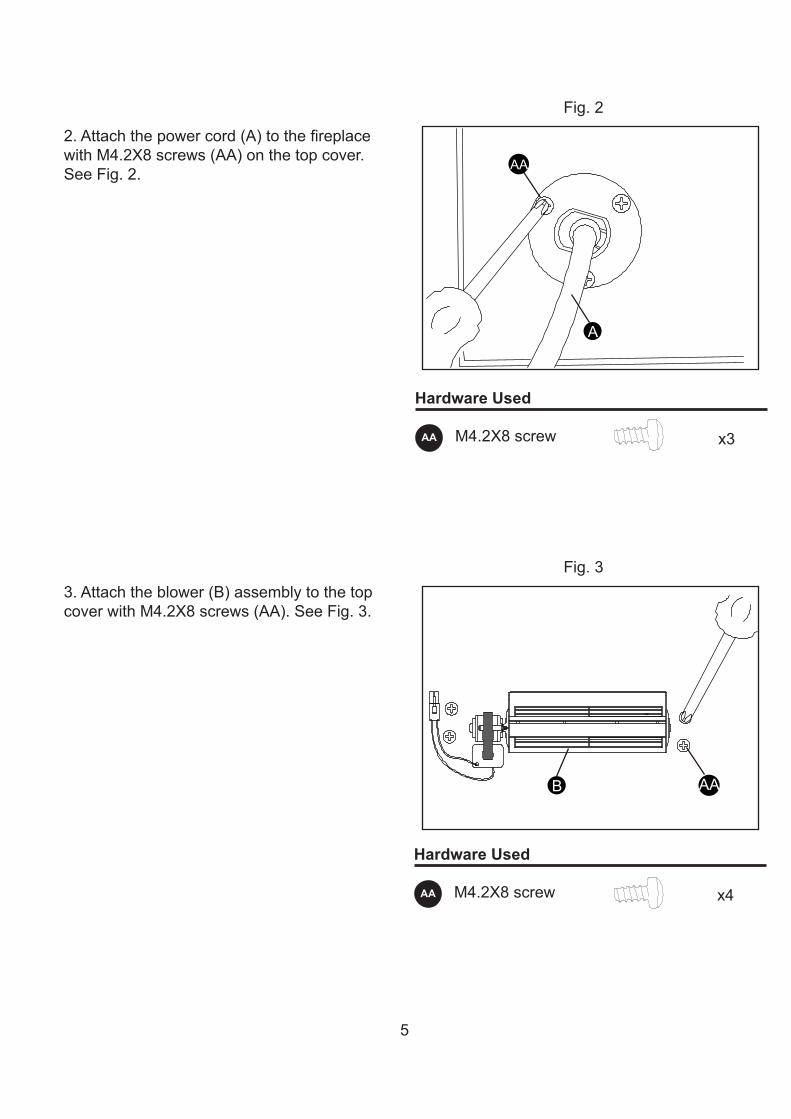
2.Attachthepowercord(A)tothefireplacewithM4.2X8screws(AA)onthetopcover.SeeFig.2.
3.Attachtheblower(B)assemblytothetopcoverwithM4.2X8screws(AA).SeeFig.3.
Hardware Used
M4.2X8screw x4AA
A
AA
B AA
6
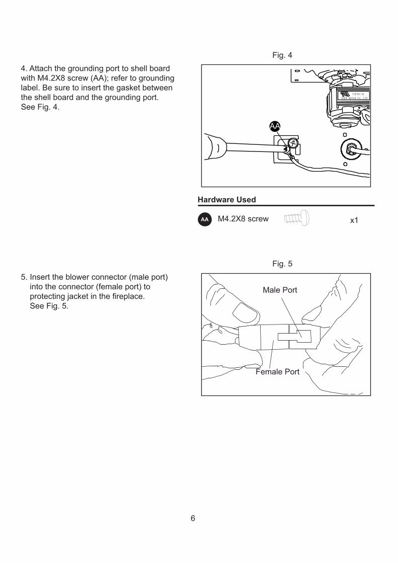
Fig.44.AttachthegroundingporttoshellboardwithM4.2X8screw(AA);refertogroundinglabel.Besuretoinsertthegasketbetweentheshellboardandthegroundingport.SeeFig.4.
Hardware Used
M4.2X8screw x1AA
5.Inserttheblowerconnector(maleport)intotheconnector(femaleport)toprotectingjacketinthefireplace.SeeFig.5.
Fig.5
AA
Male port
Female portFemalePort
MalePort
7
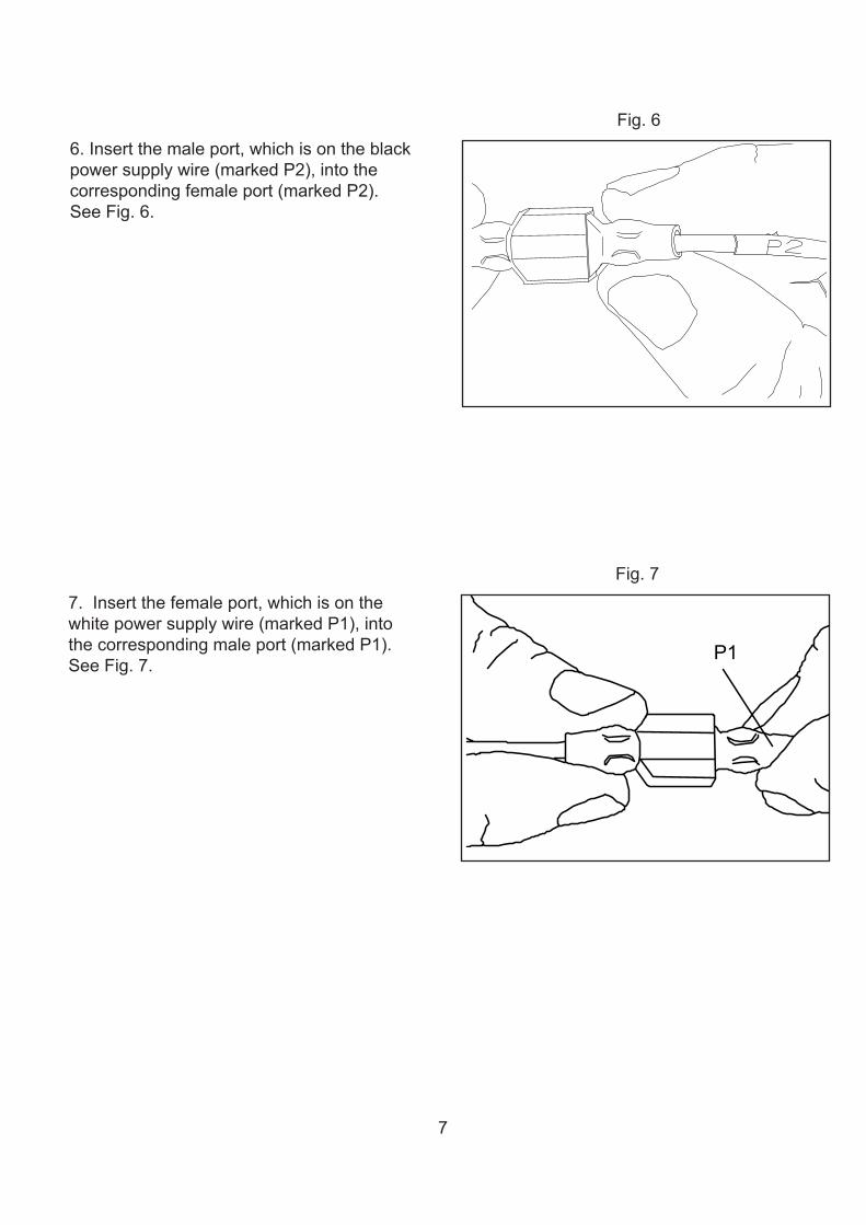
Fig.66.Insertthemaleport,whichisontheblackpowersupplywire(markedP2),intothecorrespondingfemaleport(markedP2).SeeFig.6.
Fig.77.Insertthefemaleport,whichisonthewhitepowersupplywire(markedP1),intothecorrespondingmaleport(markedP1).SeeFig.7.
P1
8
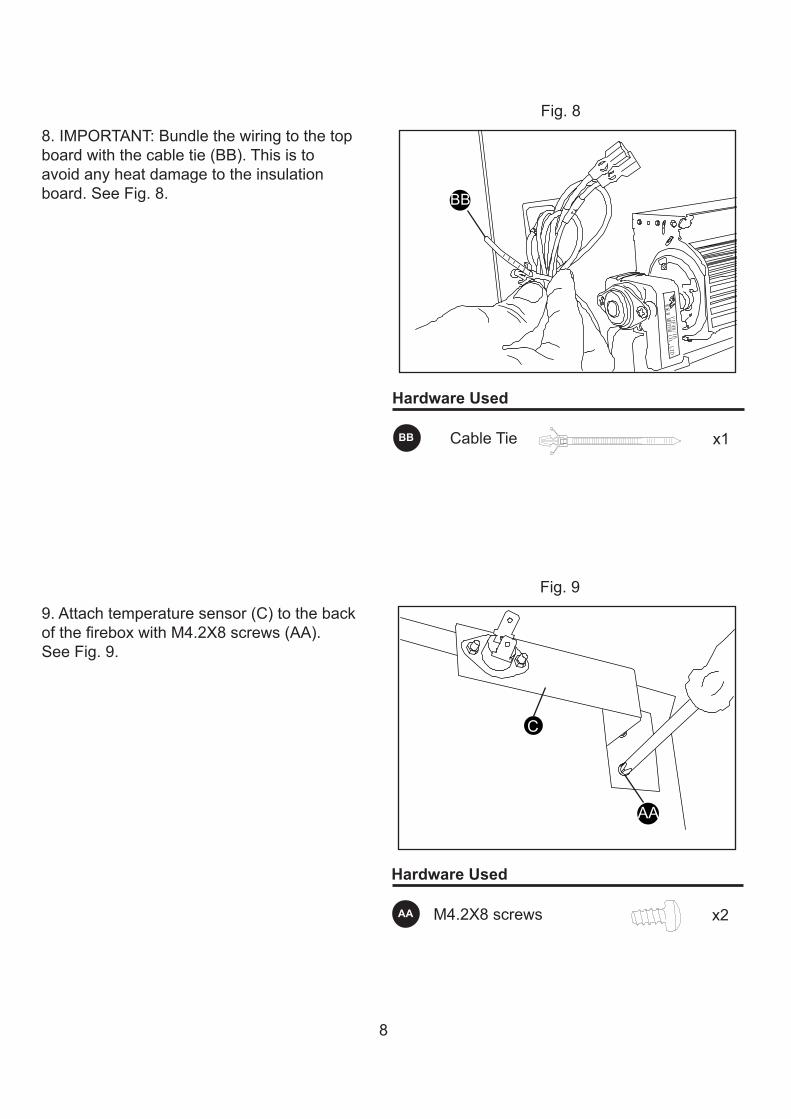
Fig.88.IMPORTANT:Bundlethewiringtothetopboardwiththecabletie(BB).Thisistoavoidanyheatdamagetotheinsulationboard.SeeFig.8.
Hardware Used
CableTie x1BB
Fig.99.Attachtemperaturesensor(C)tothebackofthefireboxwithM4.2X8screws(AA).SeeFig.9.
Hardware Used
M4.2X8screws x2AA
BB
C
AA
9
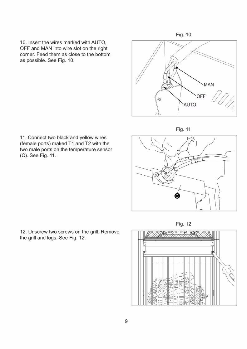
Fig.1010.InsertthewiresmarkedwithAUTO,OFFandMANintowireslotontherightcorner.Feedthemasclosetothebottomaspossible.SeeFig.10.
Fig.1111.Connecttwoblackandyellowwires(femaleports)makedT1andT2withthetwomaleportsonthetemperaturesensor(C).SeeFig.11.
Fig.1212.Unscrewtwoscrewsonthegrill.Removethegrillandlogs.SeeFig.12.
C
T1 T2
AUTO
OFF
MAN
10
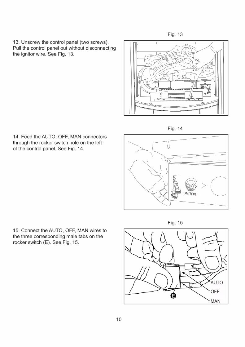
Fig.1313.Unscrewthecontrolpanel(twoscrews).Pullthecontrolpaneloutwithoutdisconnectingtheignitorwire.SeeFig.13.
Fig.1414.FeedtheAUTO,OFF,MANconnectorsthroughtherockerswitchholeontheleftofthecontrolpanel.SeeFig.14.
Fig.1515.ConnecttheAUTO,OFF,MANwirestothethreecorrespondingmaletabsontherockerswitch(E).SeeFig.15.
E
AUTO
OFF
MAN
IGNITOR
11
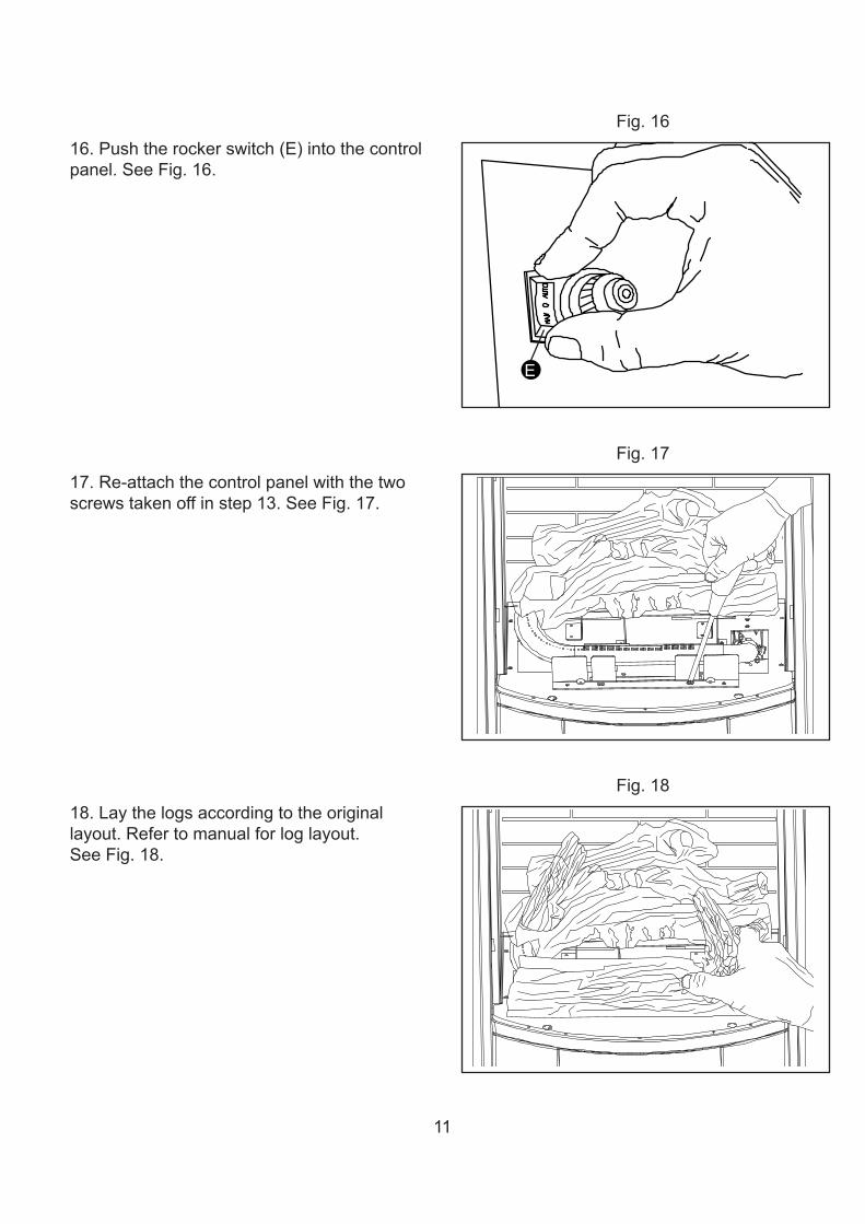
Fig.1616.Pushtherockerswitch(E)intothecontrolpanel.SeeFig.16.
Fig.1717.Re-attachthecontrolpanelwiththetwoscrewstakenoffinstep13.SeeFig.17.
Fig.1818.Laythelogsaccordingtotheoriginallayout.Refertomanualforloglayout.SeeFig.18.
E
12
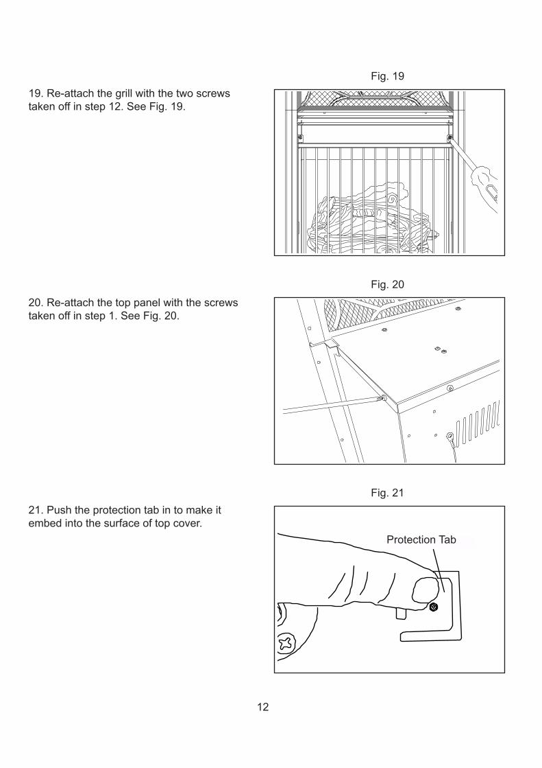
Fig.1919.Re-attachthegrillwiththetwoscrewstakenoffinstep12.SeeFig.19.
Fig.2020.Re-attachthetoppanelwiththescrewstakenoffinstep1.SeeFig.20.
Fig.2121.Pushtheprotectiontabintomakeitembedintothesurfaceoftopcover.
Protection TabProtectionTab
13
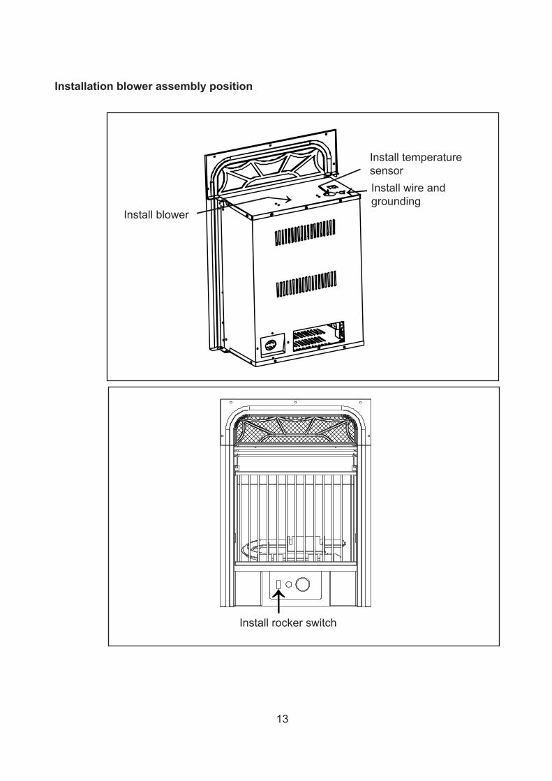
Installation blower assembly position
Installwireandgrounding
Installtemperaturesensor
Installrockerswitch
Installblower
14
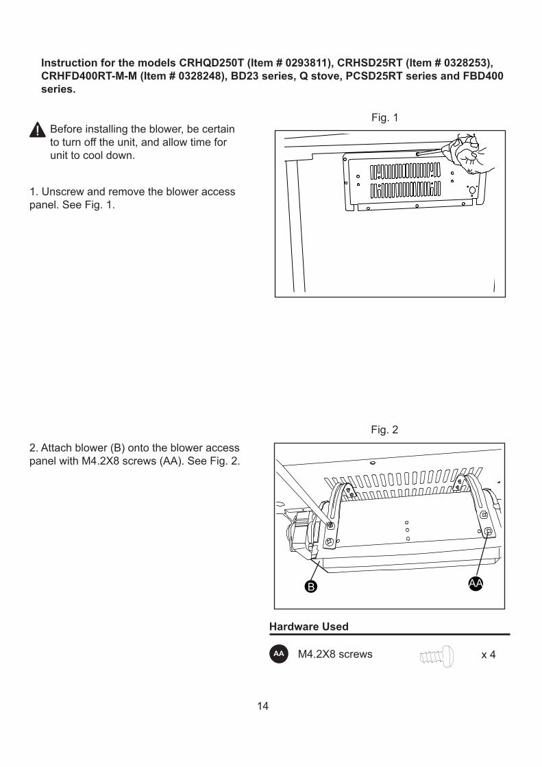
Fig.1
1.Unscrewandremovethebloweraccesspanel.SeeFig.1.
Beforeinstallingtheblower,becertaintoturnofftheunit,andallowtimeforunittocooldown.
Fig.22.Attachblower(B)ontothebloweraccesspanelwithM4.2X8screws(AA).SeeFig.2.
Hardware Used
M4.2X8screws x4AA
B AA
Instruction for the models CRHQD250T (Item # 0293811), CRHSD25RT (Item # 0328253), CRHFD400RT-M-M (Item # 0328248), BD23 series, Q stove, PCSD25RT series and FBD400 series.
15
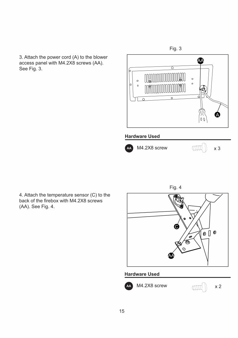
Hardware Used
M4.2X8screw x3AA
Fig.3
Fig.4
3.Attachthepowercord(A)tothebloweraccesspanelwithM4.2X8screws(AA).SeeFig.3.
4.Attachthetemperaturesensor(C)tothebackofthefireboxwithM4.2X8screws(AA).SeeFig.4.
Hardware Used
M4.2X8screw x2AA
A
AA
C
AA
16
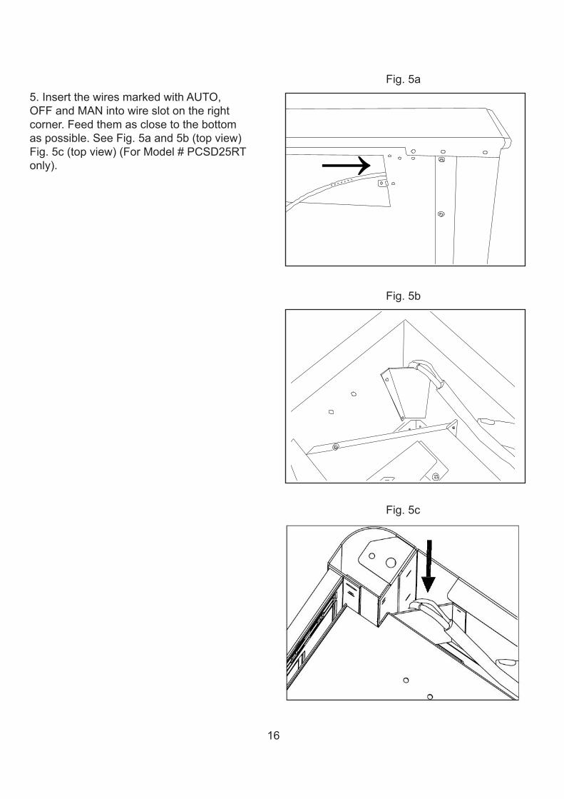
Fig.5a5.InsertthewiresmarkedwithAUTO,OFFandMANintowireslotontherightcorner.Feedthemasclosetothebottomaspossible.SeeFig.5aand5b(topview)Fig.5c(topview)(ForModel#PCSD25RTonly).
Fig.5b
Fig.5c
17
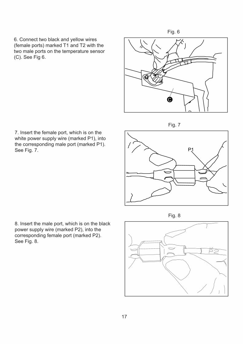
Fig.66.Connecttwoblackandyellowwires(femaleports)markedT1andT2withthetwomaleportsonthetemperaturesensor(C).SeeFig6.
Fig.77.Insertthefemaleport,whichisonthewhitepowersupplywire(markedP1),intothecorrespondingmaleport(markedP1).SeeFig.7.
Fig.88.Insertthemaleport,whichisontheblackpowersupplywire(markedP2),intothecorrespondingfemaleport(markedP2).SeeFig.8.
T1 T2
C
P1
18
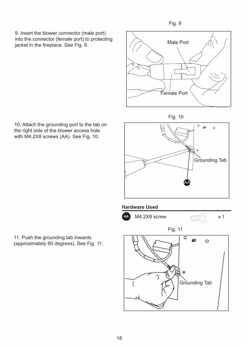
Fig.1010.AttachthegroundingporttothetabontherightsideofthebloweraccessholewithM4.2X8screws(AA).SeeFig.10.
Fig.1111.Pushthegroundingtabinwards(approximately60degrees).SeeFig.11.
Hardware Used
M4.2X8screw x1AA
Grounding Tab
AA
Grounding Tab
GroundingTab
GroundingTab
Fig.9
9.Inserttheblowerconnector(maleport)intotheconnector(femaleport)toprotectingjacketinthefireplace.SeeFig.9. Male port
Female portFemalePort
MalePort
19
Fig.12
Hardware Used
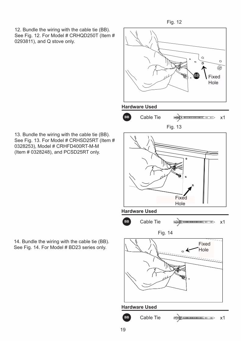
12.Bundlethewiringwiththecabletie(BB).SeeFig.12.ForModel#CRHQD250T(Item#0293811),andQstoveonly.
CableTie x1BB
Fixed Hole
BB FixedHole
Fig.13
Hardware Used
Hardware Used
13.Bundlethewiringwiththecabletie(BB).SeeFig.13.ForModel#CRHSD25RT(Item#0328253),Model#CRHFD400RT-M-M(Item#0328248),andPCSD25RTonly.
CableTie
CableTie
x1
x1
BB
BB
FixedHole
Fig.14
14.Bundlethewiringwiththecabletie(BB).SeeFig.14.ForModel#BD23seriesonly.
FixedHole
20
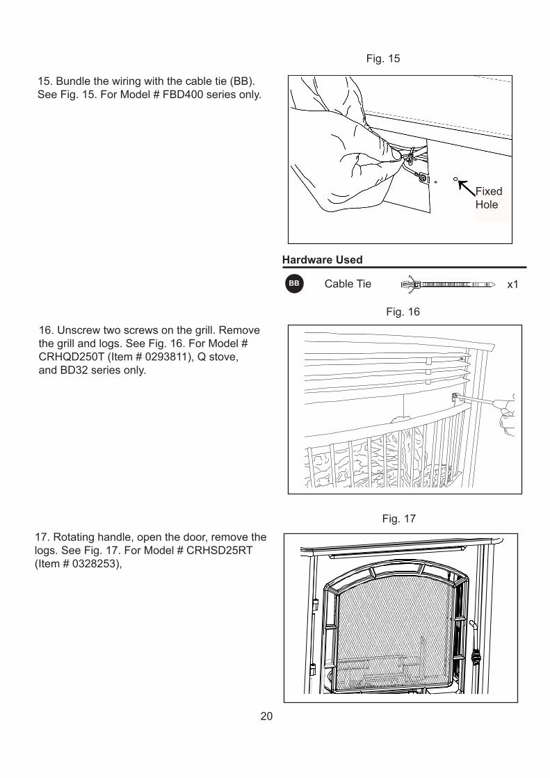
16.Unscrewtwoscrewsonthegrill.Removethegrillandlogs.SeeFig.16.ForModel#CRHQD250T(Item#0293811),Qstove,andBD32seriesonly.
Fig.16
Fig.15
17.Rotatinghandle,openthedoor,removethelogs.SeeFig.17.ForModel#CRHSD25RT(Item#0328253),
Fig.17
15.Bundlethewiringwiththecabletie(BB).SeeFig.15.ForModel#FBD400seriesonly.
FixedHole
Hardware Used
CableTie x1BB
21
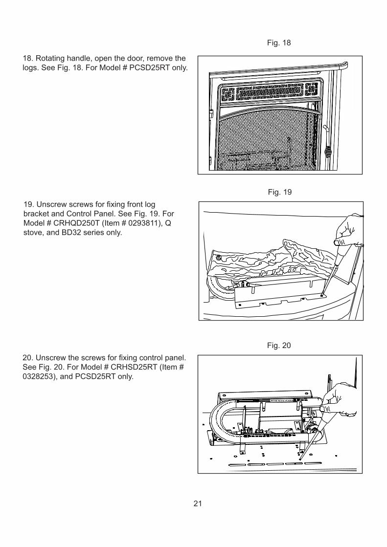
18.Rotatinghandle,openthedoor,removethelogs.SeeFig.18.ForModel#PCSD25RTonly.
Fig.18
Fig.1919.UnscrewscrewsforfixingfrontlogbracketandControlPanel.SeeFig.19.ForModel#CRHQD250T(Item#0293811),Qstove,andBD32seriesonly.
Fig.2020.Unscrewthescrewsforfixingcontrolpanel.SeeFig.20.ForModel#CRHSD25RT(Item#0328253),andPCSD25RTonly.
22
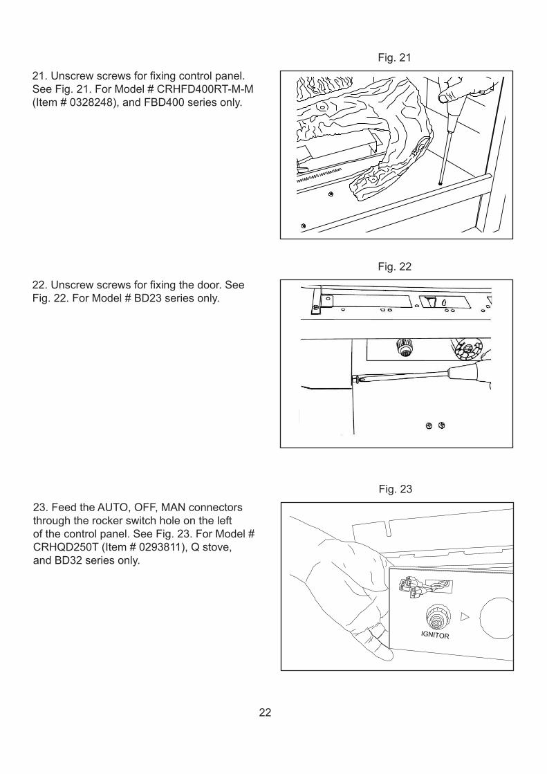
21.Unscrewscrewsforfixingcontrolpanel.SeeFig.21.ForModel#CRHFD400RT-M-M(Item#0328248),andFBD400seriesonly.
22.Unscrewscrewsforfixingthedoor.SeeFig.22.ForModel#BD23seriesonly.
Fig.21
Fig.22
Fig.2323.FeedtheAUTO,OFF,MANconnectorsthroughtherockerswitchholeontheleftofthecontrolpanel.SeeFig.23.ForModel#CRHQD250T(Item#0293811),Qstove,andBD32seriesonly.
23
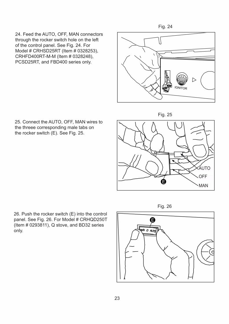
Fig.2525.ConnecttheAUTO,OFF,MANwirestothethreeecorrespondingmaletabsontherockerswitch(E).SeeFig.25.
E
AUTO
OFF
MAN
Fig.2424.FeedtheAUTO,OFF,MANconnectorsthroughtherockerswitchholeontheleftofthecontrolpanel.SeeFig.24.ForModel#CRHSD25RT(Item#0328253),CRHFD400RT-M-M(Item#0328248),PCSD25RT,andFBD400seriesonly.
Fig.2626.Pushtherockerswitch(E)intothecontrolpanel.SeeFig.26.ForModel#CRHQD250T(Item#0293811),Qstove,andBD32seriesonly.
E
24
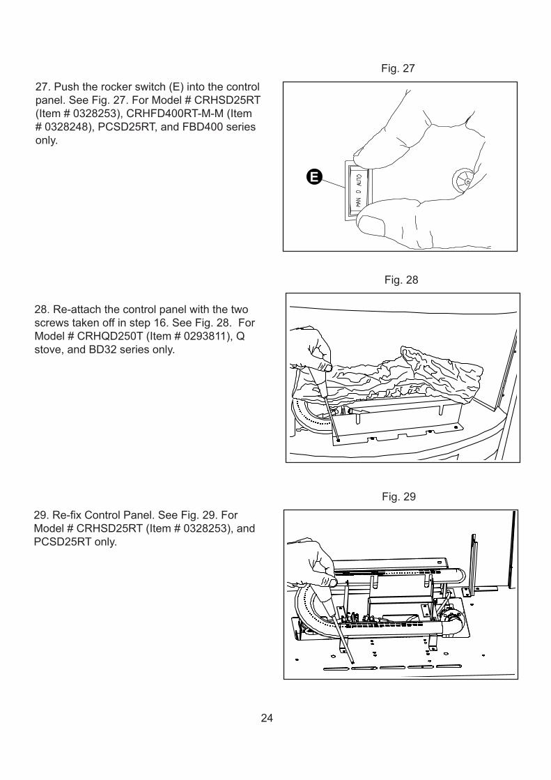
Fig.2727.Pushtherockerswitch(E)intothecontrolpanel.SeeFig.27.ForModel#CRHSD25RT(Item#0328253),CRHFD400RT-M-M(Item#0328248),PCSD25RT,andFBD400seriesonly.
E
Fig.28
28.Re-attachthecontrolpanelwiththetwoscrewstakenoffinstep16.SeeFig.28.ForModel#CRHQD250T(Item#0293811),Qstove,andBD32seriesonly.
Fig.2929.Re-fixControlPanel.SeeFig.29.ForModel#CRHSD25RT(Item#0328253),andPCSD25RTonly.
25
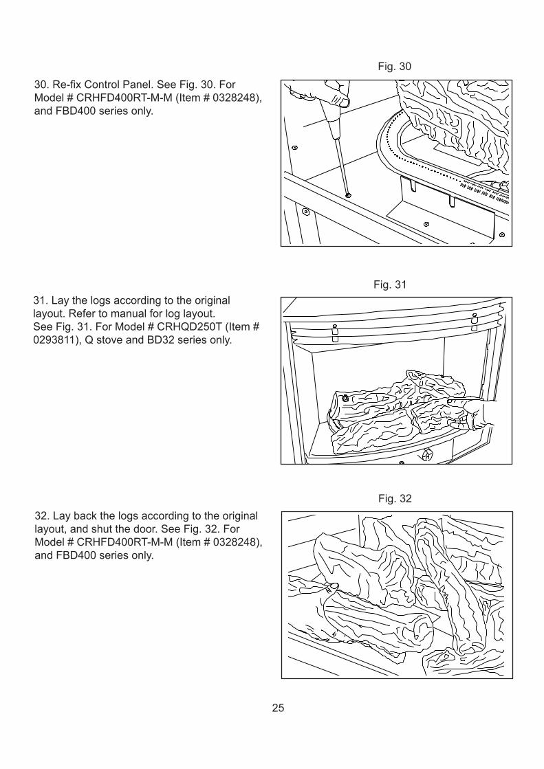
Fig.3030.Re-fixControlPanel.SeeFig.30.ForModel#CRHFD400RT-M-M(Item#0328248),andFBD400seriesonly.
Fig.3131.Laythelogsaccordingtotheoriginallayout.Refertomanualforloglayout.SeeFig.31.ForModel#CRHQD250T(Item#0293811),QstoveandBD32seriesonly.
Fig.3232.Laybackthelogsaccordingtotheoriginallayout,andshutthedoor.SeeFig.32.ForModel#CRHFD400RT-M-M(Item#0328248),andFBD400seriesonly.
26
Fig.33
Fig.34
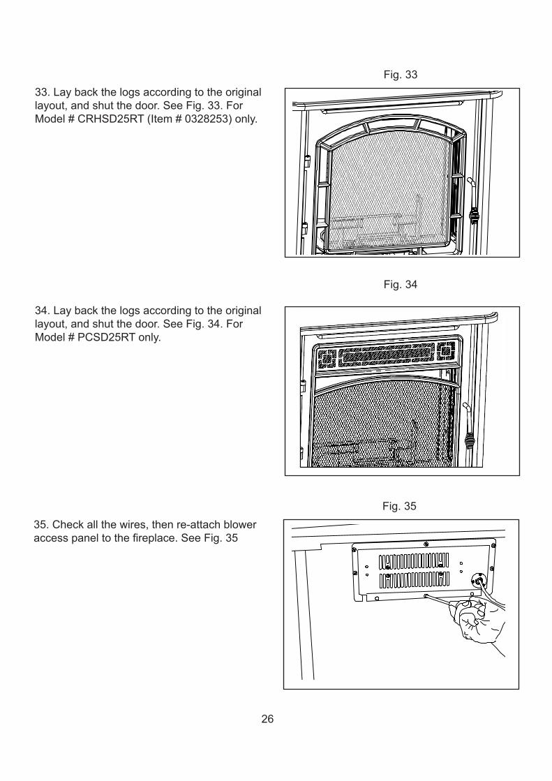
33.Laybackthelogsaccordingtotheoriginallayout,andshutthedoor.SeeFig.33.ForModel#CRHSD25RT(Item#0328253)only.
34.Laybackthelogsaccordingtotheoriginallayout,andshutthedoor.SeeFig.34.ForModel#PCSD25RTonly.
Fig.3535.Checkallthewires,thenre-attachbloweraccesspaneltothefireplace.SeeFig.35
27
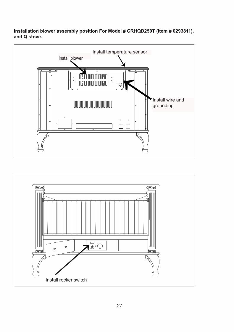
Installation blower assembly position For Model # CRHQD250T (Item # 0293811), and Q stove.
Installrockerswitch
InstallblowerInstalltemperaturesensor
Installwireandgrounding
28
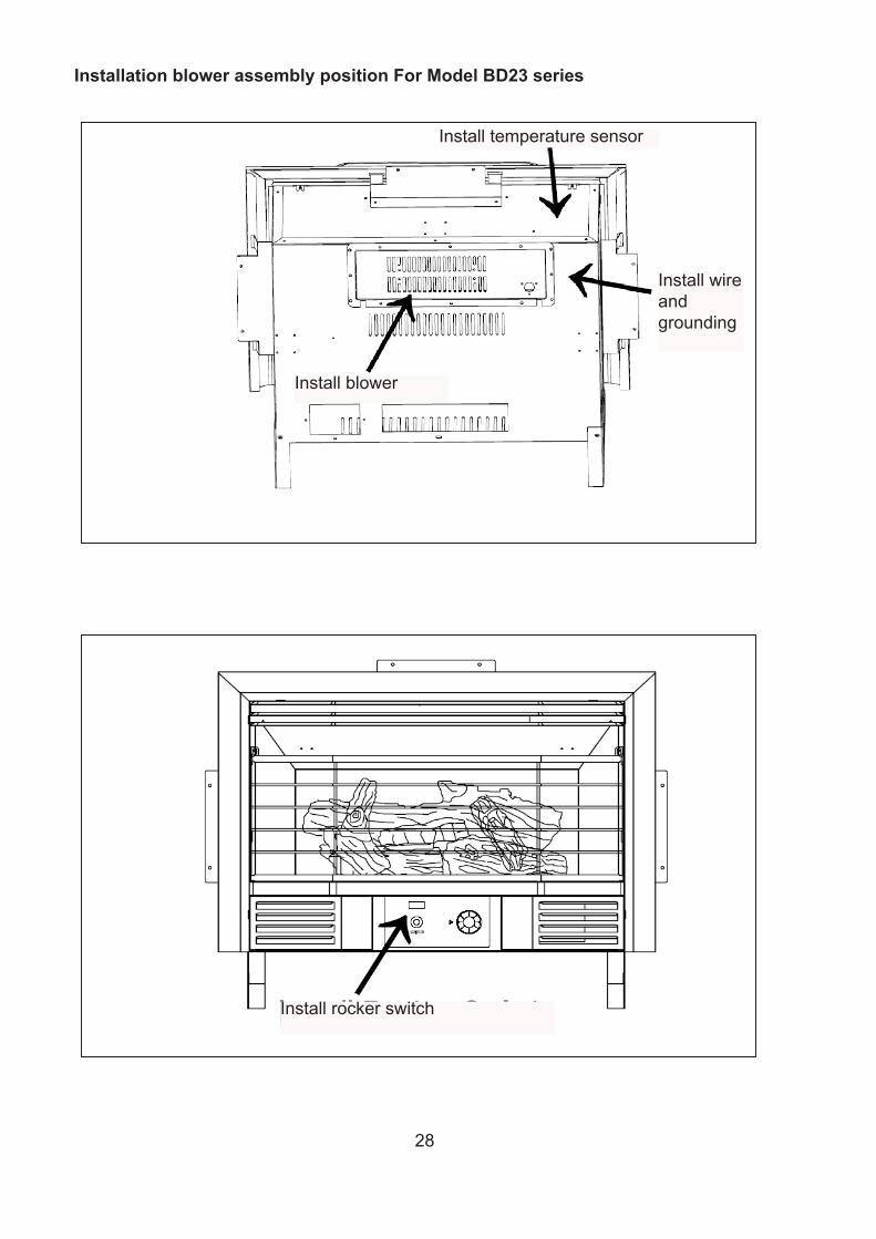
Installation blower assembly position For Model BD23 series
Installtemperaturesensor
Installwireandgrounding
Installblower
Installrockerswitch
29
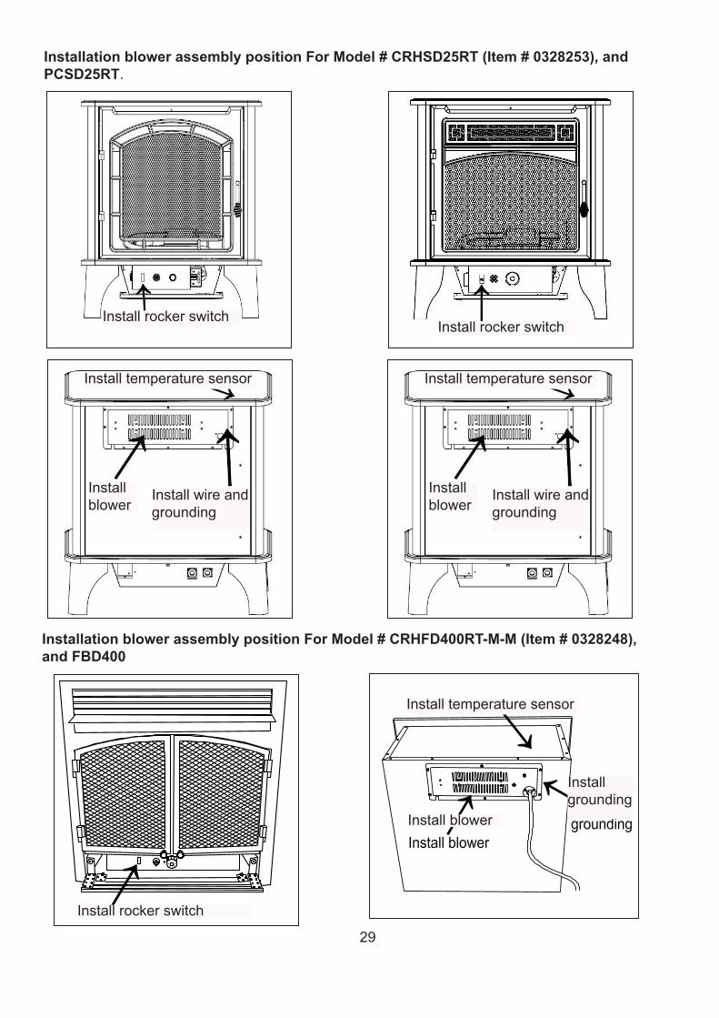
Installation blower assembly position For Model # CRHSD25RT (Item # 0328253), and PCSD25RT.
Installation blower assembly position For Model # CRHFD400RT-M-M (Item # 0328248), and FBD400
Installwireandgrounding
Installwireandgrounding
Installgrounding
Installblower
Installblower
Installblower
Installtemperaturesensor Installtemperaturesensor
Installtemperaturesensor
Installrockerswitch
InstallrockerswitchInstallrockerswitch
30
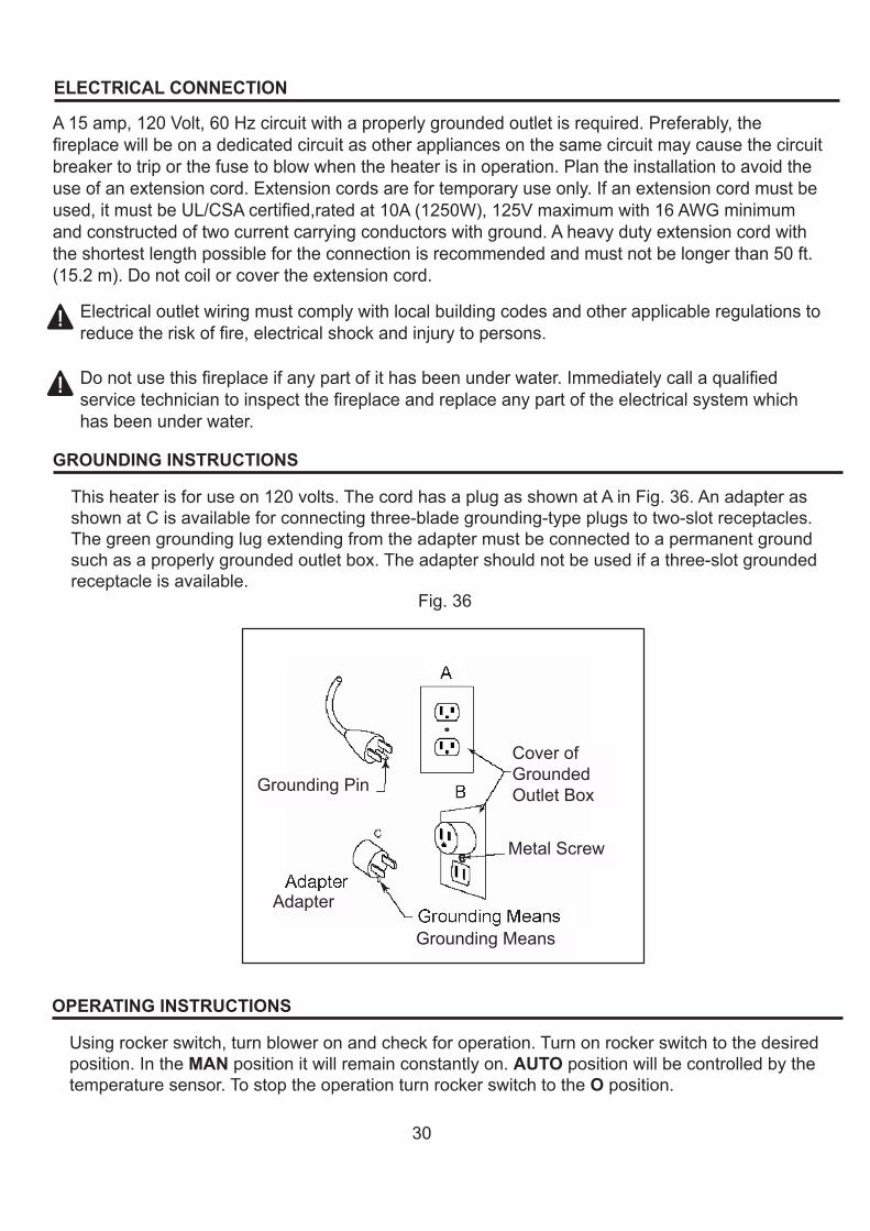
ELECTRICAL CONNECTION
A15amp,120Volt,60Hzcircuitwithaproperlygroundedoutletisrequired.Preferably,thefireplacewillbeonadedicatedcircuitasotherappliancesonthesamecircuitmaycausethecircuitbreakertotriporthefusetoblowwhentheheaterisinoperation.Plantheinstallationtoavoidtheuseofanextensioncord.Extensioncordsarefortemporaryuseonly.Ifanextensioncordmustbeused,itmustbeUL/CSAcertified,ratedat10A(1250W),125Vmaximumwith16AWGminimumandconstructedoftwocurrentcarryingconductorswithground.Aheavydutyextensioncordwiththeshortestlengthpossiblefortheconnectionisrecommendedandmustnotbelongerthan50ft.(15.2m).Donotcoilorcovertheextensioncord.
Electricaloutletwiringmustcomplywithlocalbuildingcodesandotherapplicableregulationstoreducetheriskoffire,electricalshockandinjurytopersons.
Donotusethisfireplaceifanypartofithasbeenunderwater.Immediatelycallaqualifiedservicetechniciantoinspectthefireplaceandreplaceanypartoftheelectricalsystemwhichhasbeenunderwater.
GROUNDING INSTRUCTIONS
Thisheaterisforuseon120volts.ThecordhasaplugasshownatAinFig.36.AnadapterasshownatCisavailableforconnectingthree-bladegrounding-typeplugstotwo-slotreceptacles.Thegreengroundinglugextendingfromtheadaptermustbeconnectedtoapermanentgroundsuchasaproperlygroundedoutletbox.Theadaptershouldnotbeusedifathree-slotgroundedreceptacleisavailable.
Fig.36
OPERATING INSTRUCTIONS
Usingrockerswitch,turnbloweronandcheckforoperation.Turnonrockerswitchtothedesiredposition.IntheMANpositionitwillremainconstantlyon.AUTOpositionwillbecontrolledbythetemperaturesensor.TostoptheoperationturnrockerswitchtotheOposition.
GroundingPin
Adapter
GroundingMeans
MetalScrew
CoverofGroundedOutletBox
31
CARE AND MAINTENANCE
Always disconnect the appliance from the main power supply and allow it to cool before any servicing operation.Themotorsusedonthefanheaterandflameblowerarepre-lubricatedforextendedbearinglifeandrequirenofurtherlubrication.However,periodiccleaning/vacuumingoftheappliancearoundtheairintakeandexhaust,aswellasthefanheaterisrecommended.Forheavyorcontinuoususe,periodiccleaningmustbedonemorefrequently.Iftheheaterblowsalternatingcoldandwarmair,checkthefanforfreemovementandfordebrisrestrictingairflow.Ifthefandoesnotmovefreely,theunitmustbeturnedoffandthefanreplacedimmediatelyinordertopreventfurtherdamagetotheunit.
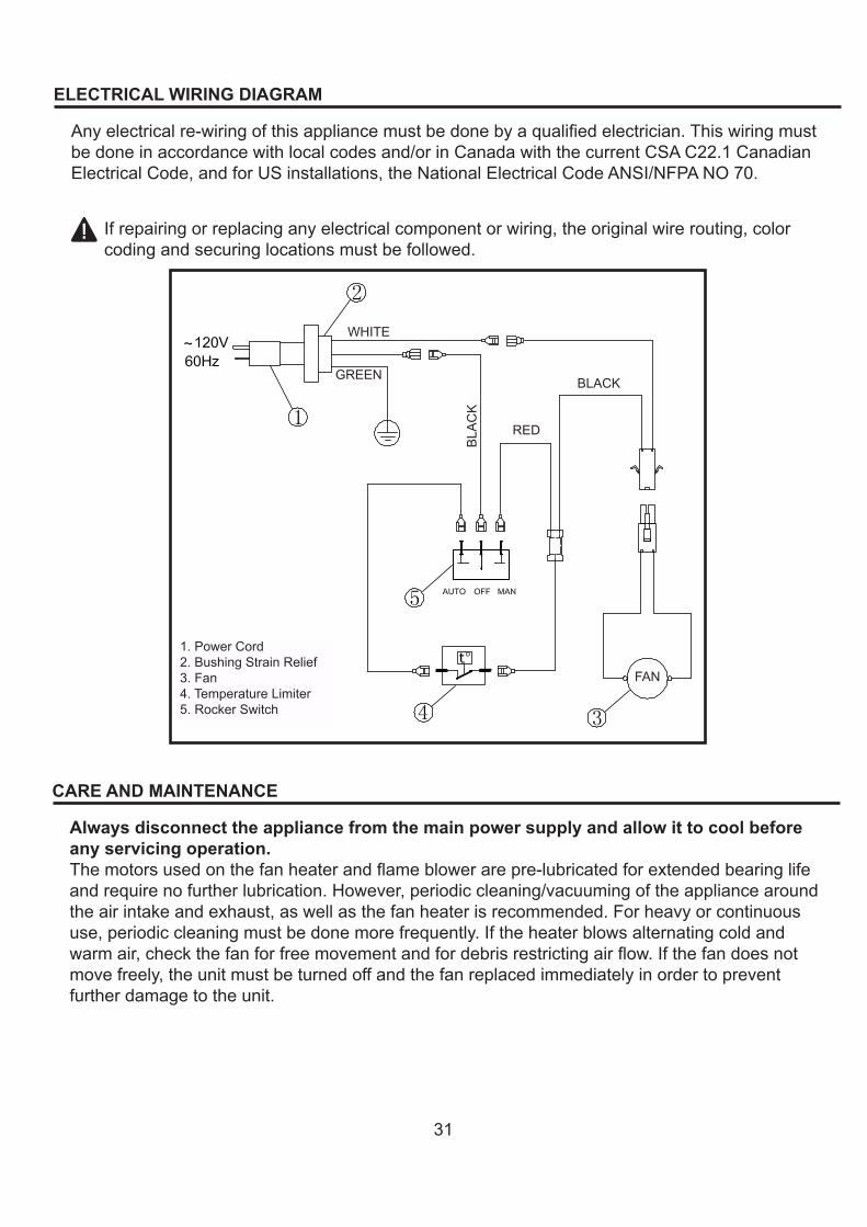
ELECTRICAL WIRING DIAGRAM
Anyelectricalre-wiringofthisappliancemustbedonebyaqualifiedelectrician.Thiswiringmustbedoneinaccordancewithlocalcodesand/orinCanadawiththecurrentCSAC22.1CanadianElectricalCode,andforUSinstallations,theNationalElectricalCodeANSI/NFPANO70.
Ifrepairingorreplacinganyelectricalcomponentorwiring,theoriginalwirerouting,colorcodingandsecuringlocationsmustbefollowed.
1.PowerCord2.BushingStrainRelief3.Fan4.TemperatureLimiter5.RockerSwitch
WHITE
GREEN BLACK
RED
FAN
BLA
CK
32
REPLACEMENT PARTS
NOTE:Useonlyoriginalreplacementparts.Thiswillprotectyourwarrantycoverageforpartsreplacedunderwarranty.
PARTS UNDER WARRANTYCallCustomerServicetollfreeat(1-877-886-5989)forreferralinformation.
WhencallingCustomerService,haveready:• Yourname• Youraddress• Modelandserialnumberofyourheater• Howheaterwasmalfunctioning• Typeofgasused(Propane/LPorNaturalgas/NG)• Purchasedate• Usually,wewillaskyoutoreturnthedefectiveparttothefactory
PARTS NOT UNDER WARRANTYCallCustomerServicetollfreeat(1-877-886-5989)forreferralinformation.
WhencallingCustomerServicehaveready:• Modelnumberofyourheater• Thereplacementpartnumber
33
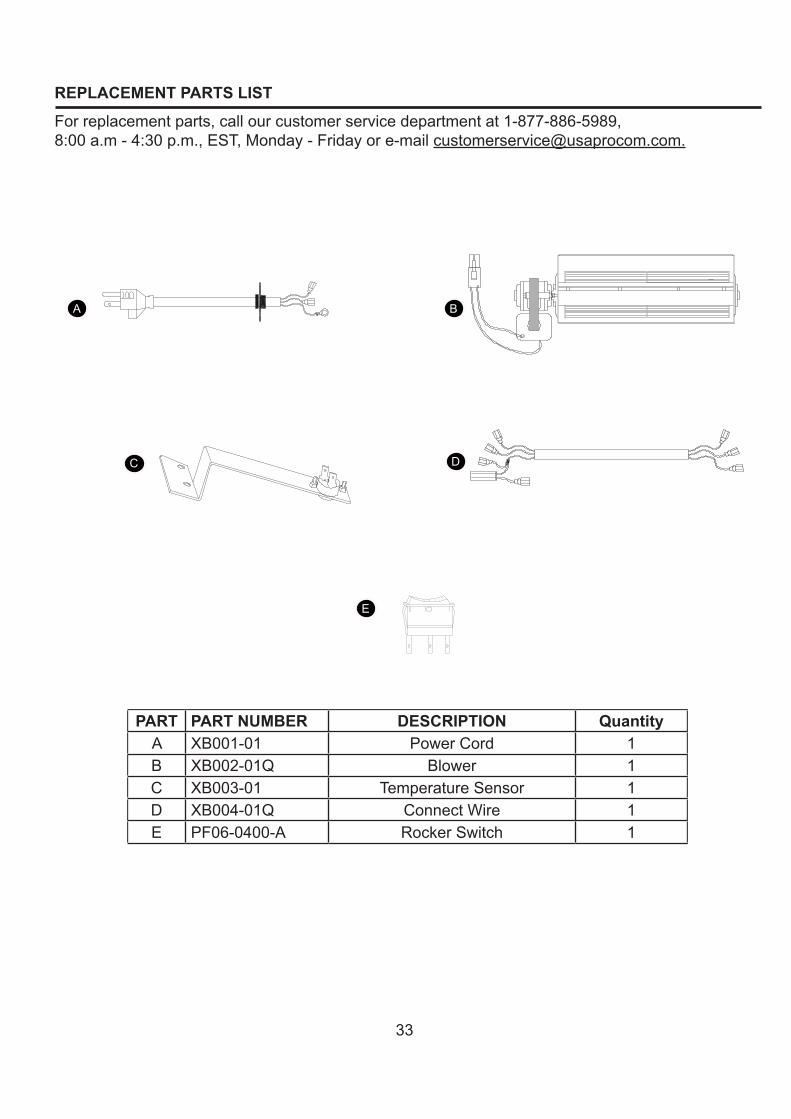
REPLACEMENT PARTS LIST
Forreplacementparts,callourcustomerservicedepartmentat1-877-886-5989,8:00a.m-4:30p.m.,EST,[email protected].
PART PART NUMBER DESCRIPTION QuantityA XB001-01 PowerCord 1B XB002-01Q Blower 1C XB003-01 TemperatureSensor 1D XB004-01Q ConnectWire 1E PF06-0400-A RockerSwitch 1
A
C
B
D
E

34
WARRANTYINFORMATIONKeepThisWarranty
IMPORTANT:WeurgeyoutofillyourwarrantyregistrationcardwithinTEN(10)daysofdateofinstallation,completewiththeentireserialnumberwhichcanbefoundontheratingplate.Retainthisportionofthecardforyourrecord.Alwaysspecifymodelandserialnumberswhencommunicatingwithcustomerservice.Wereservetherighttoamendthesespecificationsatanytimewithoutnotice.Theonlywarrantyapplicableisourstandardwrittenwarranty.Wemakenootherwarranty,expressedorimplied.
LIMITED WARRANTY:PRO-COMwarrantsthisproducttobefreefromdefectsinmaterialsandcomponentsforTWO(2)yearsfromthedateoffirstpurchase,providedthattheproducthasbeenproperlyinstalled,operatedandmaintainedinaccordancewithallapplicableinstructions,tomakeaclaimunderthiswarranty,theBillofSaleorcancelledcheckmustbepresented.
RESPONSIBILITY OF OWNERThiswarrantyisextendedonlytotheoriginalretailpurchaser.Thiswarrantycoversthecostofpart(s)requiredtorestorethisheatertoproperoperatingconditionandanallowanceforlaborwhenprovidedbyaPRO-COMAuthorizedServiceCenter.Warrantypart(s)MUSTbeobtainedthroughauthorizeddealersofthisproductand/orPRO-COMwhowillprovideoriginalfactoryreplacementparts.Failuretouseoriginalfactoryreplacementpartsvoidsthiswarranty.TheheaterMUSTbeinstalledbyaqualifiedinstallerinaccordancewithalllocalcodesandinstructionsfurnishedwiththeunit.
WHAT IS NOT COVEREDThiswarrantydoesnotapplytopartsthatarenotinoriginalconditionbecauseofnormalwearandtearorpartsthatfailorbecomedamagedasaresultofmisuse,accidents,lackofpropermaintenanceordefectscausedbyimproperinstallation.Travel,diagnosticcost,labor,transportationandanyandallsuchothercostsrelatedtorepairingadefectiveheaterwillbetheresponsibilityoftheowner.TOTHEFULLEXTENTALLOWEDBYTHELAWOFTHEJURISDICTIONTHATGOVERNSTHESALEOFTHEPRODUCT,THISEXPRESSWARRANTYEXCLUDESANYANDALLOTHEREXPRESSEDWARRANTIESANDLIMITSTHEDURATIONOFANYANDALLIMPLIEDWARRANTIES.INCLUDINGWARRANTIESOFMERCHANTABILITYANDFITNESSFORAPARTICULARPURPOSETOTWO(2)YEARSONALLCOMPONENTSFROMTHEDATEOFFIRSTPURCHASE.PRO-COM'SLIABILITYISHEREBYLIMITEDTOTHEPURCHASEPRICEOFTHEPRODUCTANDPRO-COMSHALLNOTBELIABLEFORANYOTHERDAMAGESWHATSOEVERINCLUDINGINDIRECT.INCIDENTALORCONSEQUENTIALDAMAGES.Somestatesdonotallowalimitationonhowlonganimpliedwarrantylastsoranexclusionorlimitationofaccidentalorconsequentialdamages,theabovelimitationonimpliedwarranties,orexclusionorlimitationondamagesmaynotapplytoyou.Thiswarrantygivesyouspecificlegalright,andyoumayalsohaveotherrightsthatvaryfromstatetostate.
PrintedinChina