iterative receiver in multiuser relaying systems with fast
TRANSCRIPT

Iterative Receiver in Multiuser Relaying
Systems with Fast Frequency-Hopping
Modulation
A Thesis Submitted
to the College of Graduate Studies and Research
in Partial Fulfillment of the Requirements
for the Degree of Master of Science
in the Department of Electrical and Computer Engineering
University of Saskatchewan
by
Tung T. Nguyen
Saskatoon, Saskatchewan, Canada
c© Copyright Tung T. Nguyen, September, 2013. All rights reserved.

Permission to Use
In presenting this thesis in partial fulfillment of the requirements for a Postgraduate
degree from the University of Saskatchewan, it is agreed that the Libraries of this
University may make it freely available for inspection. Permission for copying of this
thesis in any manner, in whole or in part, for scholarly purposes may be granted by
the professors who supervised this thesis work or, in their absence, by the Head of
the Department of Electrical and Computer Engineering or the Dean of the College
of Graduate Studies and Research at the University of Saskatchewan. Any copying,
publication, or use of this thesis, or parts thereof, for financial gain without the
written permission of the author is strictly prohibited. Proper recognition shall be
given to the author and to the University of Saskatchewan in any scholarly use which
may be made of any material in this thesis.
Request for permission to copy or to make any other use of material in this thesis
in whole or in part should be addressed to:
Head of the Department of Electrical and Computer Engineering
57 Campus Drive
University of Saskatchewan
Saskatoon, Saskatchewan, Canada
S7N 5A9
i

Acknowledgments
I would like to express my deepest appreciation and gratitude to my supervisor,
Professor Ha Nguyen for his great intellectual support during my studies. With his
vast knowledge and skills, he has helped me go through difficulties with constant
encouragement and influential discussions. His thoughtful advice often served to give
me a sense of direction during my M.Sc. studies. For those reasons, I am deeply
grateful for his valuable guidance and directives.
My special thanks goes to Professor Eric Salt who taught me many exciting
courses. I admire his bright wisdom and his distinguished character, whose thought-
ful instructions often go well with a great sense of humor. Without him, I would not
be able to enjoy learning that much.
I would also like to thank my family for the endless support they provided through
my entire life and in particular, I must acknowledge my wife and my brother, without
whose love, encouragement and sacrifice, I would not have finished this thesis.
ii

Abstract
In this thesis, a novel iterative receiver and its improved version are proposed for
relay-assisted multiuser communications, in which multiple users transmit to a des-
tination with the help of a relay and using fast frequency-hopping modulation. Each
user employs a channel encoder to protect its information and facilitate interference
cancellation at the receiver. The signal received at the relay is either amplified, or
partially decoded with a simple energy detector, before being forwarded to the des-
tination. Under flat Rayleigh fading channels, the receiver at the destination can
be implemented non-coherently, i.e., it does not require the instantaneous channel
information to demodulate the users’ transmitted signals. The proposed iterative
algorithm at the destination exploits the soft outputs of the channel decoders to
successively extract the maximum likelihood symbols of the users and perform inter-
ference cancellation. The iterative method is successfully applied for both cases of
amplify-and-forward and partial decode-and-forward relaying. The error performance
of the proposed iterative receiver is investigated by computer simulation. Under the
same spectral efficiency, simulation results demonstrate the excellent performance of
the proposed receiver when compared to the performance of decoding without inter-
ference cancellation as well as the performance of the maximum likelihood multiuser
detection previously developed for uncoded transmission. Simulation results also sug-
gest that a proper selection of channel coding schemes can help to support significant
more users without consuming extra system resources.
In addition, to further enhance the receiver’s performance in terms of the bit error
rate, an improved version of the iterative receiver is presented. Such an improved re-
ceiver invokes inner-loop iterations between the channel decoders and the demappers
in such a way that the soft outputs of the channel decoders are also used to refine the
outputs of the demappers for every outer-loop iteration. Simulation results indicate
a performance gain of about 2.5dB by using the two-loop receiver when compared to
the performance of the first proposed receiver.
iii

Table of Contents
Permission to Use i
Acknowledgments ii
Abstract iii
Table of Contents iv
List of Figures vi
List of Abbreviations viii
1 Introduction 1
2 Background 8
2.1 Relay Communications . . . . . . . . . . . . . . . . . . . . . . . . . . 8
2.1.1 Relaying Topologies . . . . . . . . . . . . . . . . . . . . . . . . 9
2.1.2 Relay Classification . . . . . . . . . . . . . . . . . . . . . . . . 11
2.2 Fading and Frequency Hopping Spread Spectrum . . . . . . . . . . . 13
2.3 Fast Frequency Hopping and Non-coherent Detection . . . . . . . . . 16
2.3.1 FFH-MA Communication System . . . . . . . . . . . . . . . . 17
2.3.2 Conventional Detection of FFH Signals . . . . . . . . . . . . . 20
2.3.3 Joint Maximum Likelihood Detection . . . . . . . . . . . . . . 22
2.3.4 Iterative Interference Cancellation (IIC) . . . . . . . . . . . . 23
3 Multi-User Relaying System with FFH Modulation 25
3.1 Introduction . . . . . . . . . . . . . . . . . . . . . . . . . . . . . . . . 25
iv

3.2 System Model . . . . . . . . . . . . . . . . . . . . . . . . . . . . . . . 27
3.2.1 Information Transmission of Users . . . . . . . . . . . . . . . . 28
3.2.2 Amplify-and-Forward Relaying . . . . . . . . . . . . . . . . . 30
3.2.3 Partially Decode-and-Forward Relaying . . . . . . . . . . . . . 32
3.2.4 Receiver at the Destination . . . . . . . . . . . . . . . . . . . 35
3.3 Interference Cancellation . . . . . . . . . . . . . . . . . . . . . . . . . 40
3.3.1 AF Relaying . . . . . . . . . . . . . . . . . . . . . . . . . . . . 40
3.3.2 Partial DF Relaying . . . . . . . . . . . . . . . . . . . . . . . 43
3.4 Simulation Results . . . . . . . . . . . . . . . . . . . . . . . . . . . . 46
4 Improved Receiver with Inner-Loop Iterations 52
4.1 Introduction . . . . . . . . . . . . . . . . . . . . . . . . . . . . . . . . 52
4.2 Structure of the Two-Loop Receiver . . . . . . . . . . . . . . . . . . . 54
4.3 Simulation Results and Discussion . . . . . . . . . . . . . . . . . . . . 57
5 Conclusions and Suggestions for Further Research 61
5.1 Conclusions . . . . . . . . . . . . . . . . . . . . . . . . . . . . . . . . 61
5.2 Suggestions for Further Research . . . . . . . . . . . . . . . . . . . . 62
A Log-Domain Computations 64
B Sub-Optimal Log-MAP Algorithms 66
B.1 Max-Log-MAP Algorithm . . . . . . . . . . . . . . . . . . . . . . . . 66
B.2 Max-Star Algorithm . . . . . . . . . . . . . . . . . . . . . . . . . . . 67
References 69
v

List of Figures
1.1 Multi-user one-way relaying system. . . . . . . . . . . . . . . . . . . . 4
2.1 Wireless communications: (a) Single-hop direct transmission, and (b)
Two-hop relay transmission. . . . . . . . . . . . . . . . . . . . . . . . 9
2.2 Overcome shadowing by employing a relay. . . . . . . . . . . . . . . . 9
2.3 One-way relaying: (a) Multiple relays help one user; (b) Single relay
helps multiple users. . . . . . . . . . . . . . . . . . . . . . . . . . . . 10
2.4 Multi-way relaying. . . . . . . . . . . . . . . . . . . . . . . . . . . . . 11
2.5 Amplify-and-Forward relaying. . . . . . . . . . . . . . . . . . . . . . . 12
2.6 Decode-and-Forward relaying. . . . . . . . . . . . . . . . . . . . . . . 13
2.7 Example of deep fades in a Rayleigh fading channel . . . . . . . . . . 14
2.8 Example of Slow-Frequency-Hopping in GSM . . . . . . . . . . . . . 15
2.9 Structure of a FFH-MA communication system. . . . . . . . . . . . . 17
2.10 An example of different designs of frequency hopping addresses. . . . 19
2.11 Conventional FFH detector. . . . . . . . . . . . . . . . . . . . . . . . 20
2.12 TF matrices at destination. . . . . . . . . . . . . . . . . . . . . . . . 22
3.1 Two models of relay networks: (a) Multiuser one-way relaying and (b)
Multiuser multi-way relaying. . . . . . . . . . . . . . . . . . . . . . . 27
3.2 Structure of the kth user’s transmitter. . . . . . . . . . . . . . . . . . 28
3.3 Structure of AF relaying. . . . . . . . . . . . . . . . . . . . . . . . . . 30
vi

3.4 Structure of partial DF relaying. . . . . . . . . . . . . . . . . . . . . . 32
3.5 Structure of the receiver at the destination. . . . . . . . . . . . . . . . 36
3.6 Example illustrating the proposed iterative receiver: (a) Hard and soft
outputs after each iteration, (b) Updating process of feedback matrix
U[ν]n . . . . . . . . . . . . . . . . . . . . . . . . . . . . . . . . . . . . . 39
3.7 BER performance of the AF relaying system with M = 16. . . . . . . 47
3.8 BER performance of the proposed partial DF relaying system with
M = 16. . . . . . . . . . . . . . . . . . . . . . . . . . . . . . . . . . . 48
3.9 BER performance of the proposed partial DF relaying system with
M = 32. . . . . . . . . . . . . . . . . . . . . . . . . . . . . . . . . . . 49
3.10 Overall BER versus the number of users for the proposed partial DF
relaying system with M = 32 and γb = 20 dB. . . . . . . . . . . . . . 51
4.1 Transmitter and receiver of a BICM-ID system. . . . . . . . . . . . . 53
4.2 Structure of the two-loop receiver. . . . . . . . . . . . . . . . . . . . . 54
4.3 BER performance comparison between the improved receiver withM =
16 and 5 inner-loop iterations (solid lines) and the receiver in Chapter
3 without inner-loop (dashed lines). . . . . . . . . . . . . . . . . . . . 58
4.4 BER comparison for different numbers of inner-loop iterations. . . . . 59
4.5 BER performance of single-user system with different numbers of inner-
loop iterations. . . . . . . . . . . . . . . . . . . . . . . . . . . . . . . 60
vii

List of Abbreviations
M-FSK M-ary Frequency Shift Keying
AF Amplify-and-Forward
BER Bit Error Rate
CDMA Code Division Multiple Access
DF Decode-and-Forward
DPSK Differential Phase-Shift Keying
FDMA Frequency-Division Multiple Access
FEC Forward Error Correction
FFH Fast Frequency Hopping
FH Frequency Hopping
FHMA Frequency Hopping Multiple Access
GSM Global System for Mobile Communications
IIC Iterative Interference Cancellation
LDPC Low-Density Parity-Check
MA Multiple-Access
MAI Multiple Access Interference
MAP Maximum A Posteriori Probability
ML Maximum Likelihood
ML-MUD Maximum-Likelihood Multiuser Detector
viii

MUI Multiuser Interference
PDAF Partial Decode-and-Forward
SFH Slow Frequency Hopping
SIC Soft Interference Cancellation
SISO Soft Input Soft Output
TDMA Time-Division Multiple Access
TF Time-Frequency
ix

1. Introduction
Wireless communication networks are being considered as the fastest growing seg-
ment of the communication industry [1]. Before becoming one of the most crucial
technologies for everyday life, it had a long history of development [2]. In 1865,
Maxwell published his theoretical work on describing the movement of electromag-
netic waves through space, which set a milestone in radio communication. Before the
publication of Maxwell’s work, people had no idea about the existence of “waves”
that cannot be seen by bare eyes. Maxwell, by the way, had never seen a radio and
had no actual experience with radio waves himself. But his theories paved the way
for the next set of crucial inventions. First, an experiment which marked the birth
of radio transmission was performed in 1897, when Marconi sent a radio telegraph
across the English Channel [3]. The public use of radio began in 1907 and there have
been so many great contributions since then, including the works of Armstrong (who
invented wide-band frequency modulation), De Forest (who created the amplifying
vacuum tubes) and Viterbi (who came up with digital decoding and code-division
multiple access (CDMA) technique) and so many more that are not possible to list
here. Now there are more people working in wireless communication industry than
at any other time in history [4]. Wireless communication systems have experienced
exponential growth over the last decades and there are currently more than six billion
subscribers worldwide [5].
While having the ability to send information over the air, wireless communication
systems often suffer from channel attenuations due to propagation path loss, shad-
owing loss and absorption loss. Furthermore, a signal transmitted through a wireless
1
channel typically experiences random variations due to the presence of objects in the
signal path, giving rise to random variations of the received power at the destination.
Such random variations are generally referred to as fading effect which varies in time
and depends on the geographical positions of transmitters and receivers. To main-
tain the quality of data services under such fading environment, one can increase the
transmit power, employ a wider transmission bandwidth or use multi-input multi-
output communications [6]. However, due to size, cost, and/or hardware limitations,
a wireless device may not be able to support such multiple-antenna implementation.
For those reasons, relay-assisted transmission has emerged as one of the promising
solutions to deal with the fading problem.
A relay is a system that receives and retransmits the signal among stations or
between base stations and mobile devices. By doing so, a relay can help increasing
the throughput and/or extending the coverage of a wireless communication system.
The infrastructure of wireless relays does not need any wired connection and it can be
installed at either a fixed station or a mobile vehicle. Furthermore, a relay’s structure
is often less complex and consumes less power than a base station. Relay transmission,
therefore, offers overall cost saving when being used in a wireless communication
system. As a matter of fact, during the 1950s, AT&T had established a long-distance
wireless link between New York and Boston using relays [7]. The main reason was that
a direct communication link would not be possible due to the curvature of the earth
and natural obstacles. A few decades later, people witnessed the success of satellite
communications [8]. In such an application, a satellite plays the role of a relay and
was often refereed to as a “mirror” or “repeater” in outer space. A satellite receives
message signals from a sender and may forward the messages to some other satellites
so that the messages can be transmitted back to the earth. Being considered the only
truly commercial space technology, generating billions of dollars annually in sales of
products and services, satellite communication has motivated the theoretical study
of relay systems in early 1970s. Since then, deploying relays has become essential in
any long distance communication systems.
2

Influenced by the rapid development of wireless radios, personal communication
devices are being made smaller and become more accessible to majority of human
population. Consequently, communication networks are becoming larger with the ca-
pability of serving multiple devices at the same time. It is common that two or more
geographically separated nodes attempt to exchange binary data simultaneously [9].
This scenario is generally known as a multiple-access (MA) communication system,
which was originally studied by Liao [10] in 1972 and has been followed by many
researchers [11–13]. It is pointed out that using channel coding is essential for mul-
tiple access channels [13] as it provides crucial information protection. Moreover,
using channel coding makes the output signals (from multiple transmitters) uncor-
related. This is beneficial since it has been shown that the capacity of a multiple
access channel, which is equal to the mutual information between the input and out-
put of the channel, is maximized when all the transmitted signals are statistically
independent [10]. Early investigation on code construction for MA channels focuses
mainly on block coding [14–16] and the maximum achievable capacity was analyzed.
However, block-coded MA systems require different constituent codes at the transmit-
ters, thus introducing extra complexity to both the transmitting and receiving sides.
Fortunately, inspired by the success of turbo codes [17, 18], a simple, yet effective
approach for coding in a MA system was found with the introduction of interleaving
and iterative processing. Interleaving is a low-complexity operation that often takes
place after forward error correction (FEC) coding. The possibility of employing inter-
leaving for user separation has been widely investigated in [19–21]. Furthermore, the
ability to approach the capacity of a MA channel has been demonstrated for systems
using interleaving [22, 23].
This thesis is concerned with an MA wireless communication system, in which
multiple users wish to reliably deliver their information to a receiver with the help
of a relay. The model is shown in Fig. 1.1. Since the relay operates in a half-duplex
mode, i.e., it cannot transmit and receive at the same time, communication between
sources and destination is carried out in two time slots. In the first time slot, the
3

Source 1 Encoder 1P
User 1
Source 2 Encoder 2P
User 2
Source K Encoder KP
User K
. . .
Multiple access
channelRelay
Multiuser
detector
Destination
Figure 1.1 Multi-user one-way relaying system.
relay receives signals transmitted simultaneously from all users. It then processes and
forwards the result to the destination in the second time slot. Also note that during
the first time slot, signal from one user should not severely interfere with signals
from other users. This can be done by using an appropriate channel access method.
For example, signals from multiple users can be separated in the time domain (by
using time-division multiple access (TDMA)), frequency domain (by using frequency-
division multiple access (FDMA)) or code domain (by using code-division multiple
access (CDMA)).
When fast frequency hopping (FFH) [24] is selected as the modulation technique,
multi-user signals can only be made semi-orthogonal in both frequency and time
domains. However, by using FFH modulation for all transmission links, the system
can benefit from:
• Frequency diversity: By dividing the system’s bandwidth into many sub-
bands, the main advantage of FFH modulation is that it is highly tolerant
of narrow-band interference. The FFH modulation, therefore, can also effec-
tively mitigate the inherent fading effects of wireless transmission. With high
4

frequency diversity order, the FFH system can co-operate with other systems
employing different modulation types by sharing the same frequency band.
• Time diversity: One FFH symbol is spread to multiple hops in different time
slots. The hopping is considered non-coherently related, thus making the FFH
system resistant to burst noise.
• Non-coherent detection: Owing to the fact that FFH signals can be detected
non-coherently, the impacts of phase distortion and frequency offset are mini-
mized with this modulation method. Also, without requiring the channel state
information (CSI), the receiver’s structure can be simplified.
For the system in Fig. 1.1, the main source of performance degradation comes
from multiple access interference (MAI) in the first time slot, which also propagates
to the destination in the second time slot. MAI, also known as multiuser interference
(MUI) arises because signals from multi-users are not completely orthogonal, which
is an inherent issue of FFH modulation. The system performance therefore depends
on how well the receiver can distinguish one’s transmitted signal from the others.
For the past few decades, there were significant research studies on multi-user detec-
tion (MUD). While it is commonly known that the maximum-likelihood (ML) joint
multi-user detection gives the best performance, its excessively high computational
complexity makes it very expensive (in terms of hardware cost), if not impossible, for
practical implementation [25]. This difficulty motivates the iterative processing ap-
proach, which was introduced shortly after the discovery of turbo codes. In contrast
to the classical approach, where demodulating and decoding are performed separately
one after another, an iterative receiver exchanges probabilistic quantities among its
modules and gradually approaches the optimum detection bound [26]. Specifically,
the iterative processing principle allows earlier stages (e.g., the demodulator) to re-
fine their processing based on information obtained from later stages (e.g., channel
decoder). While most contributions on iterative receivers focus on CDMA and point-
to-point communications, no iterative multi-user receiver for FFH modulated system
5
has been developed for wireless relay networks. Developing an iterative receiver at
the destination node for the system in Fig. 1.1 is precisely the main objective of this
thesis.
The remainder of this chapter gives an overview of the thesis’ contributions and
its organization.
In Chapter 2, a background of multi-user one-way relay systems considered in
this thesis is provided. Different scenarios of relay communications are discussed. In
addition, the advantages and disadvantages of different signal processing methods,
including amplify-and-forward, decode-and-forward as well as partial decode-and-
forward are explained. The purpose is to give a general introduction to systems
investigated in the literature that are related to the work in this thesis. Relevant to
the iterative receiver proposed in this thesis, the technique of FFH modulation with
non-coherent detection are also described in this chapter. Conventional algorithms
to detect FFH signals will also be presented.
Chapter 3 starts with an introduction of the multi-user relay system under con-
sideration. To facilitate the transmission from sources to a destination via a relay,
two relaying schemes are presented. The first scheme is the well-known amplify-and-
forward relaying, while the second scheme is a threshold-based partial decode-and-
forward relaying, which is specifically designed for FFH modulation. Depending on
the signal processing scheme employed at the relay, the receiver at the destination
needs to detect the information transmitted by multiple users. Exploiting the unique
pattern of the signal from each user, a method to jointly detect multiple users’ signals
is developed. The proposed detection algorithm relies on the soft interference can-
cellation (SIC) that incorporates feedback information from the decoders. For both
relaying schemes mentioned above, the performance of the proposed receiver shows
a remarkable improvement over the conventional uncoded system under the same
spectral efficiency. In addition, while the partial decode-and-forward relaying scheme
requires extra complexity at the relay, its corresponding receiver at the destination is
simpler but yields better performance than the amplify-and-forward relaying scheme.
6

Chapter 4 presents an important improvement to the receiver designed in Chap-
ter 3. Specifically, by introducing a soft demapper between the SIC module and the
channel decoder, the iterative process is expanded so that probabilistic soft informa-
tion is exchanged among three modules: the interference canceller, the soft demapper
and the channel decoder. The receiver is designed to incorporate an inner iterative
process between the soft demapper and the channel decoder to further refine the out-
come of the multi-user detector. This in effect introduces two-loop operation: The
outer-loop processing is where the soft information is exchanged between the SIC and
the channel decoder, whereas for the inner-loop processing the extrinsic information
is passed between the soft demapper and the channel decoder. Simulation results are
also provided in this chapter to demonstrate performance superiority of the improved
receiver.
Finally, Chapter 5 draws conclusions and offers suggestions for further studies.
7

2. Background
2.1 Relay Communications
In conventional wireless communication systems, data transmission occurs directly
between the transmitter and the receiver. This scenario is commonly known as single-
hop communication, as shown in Fig. 2.1-(a). A mobile terminal (user node) tries
to communicate with a base station (destination node) without any help of interme-
diate devices. However, a user node could be located outside the service area of the
destination or located in an unfavorable location resulting in coverage dead spots.
For example, a user node could be surrounded by large buildings or located in a val-
ley shadowed by mountains. Such situations elevate the effect of path-loss, which is
caused by the reduction of power density of an electromagnetic wave as it propagates
through space. As such, the demand for constant data service requires appropriate
techniques to combat signal attenuations in such situations.
Relaying or two-hop communication is a practical solution for extending the cover-
age area in a cost effective way. Relaying implies that the original transmitted signal
passes through one or more intermediate nodes before reaching the destination. As il-
lustrated in Fig. 2.1-(b), a relay splits a longer communication path into shorter ones,
therefore providing the ability to reduce overall path-loss. Moreover, by employing
a relay, source-destination communication link can be re-routed around obstacles to
overcome shadowing loss, as seen in Fig. 2.2. Typically, relaying is considered as an
add-on to traditional point-to-point wireless systems, whose main goal is to boost the
system’s performance under severe signal attenuations.
8

a) b)
User node
Destination Destination
User nodeRelay
Figure 2.1 Wireless communications: (a) Single-hop direct transmission, and (b)
Two-hop relay transmission.
DestinationUser node
Relay
Figure 2.2 Overcome shadowing by employing a relay.
2.1.1 Relaying Topologies
Different relaying topologies have been proposed so that single/multiple relay(s)
can effectively help single/multiple source(s) to communicate with single/multiple
destination(s). In this section, two variants of relaying topologies are presented,
which are one-way relaying and multi-way relaying.
One-Way Relaying
The most basic relying setup, as illustrated in Fig. 2.1-(b), consists of a single user
and a single destination, with one relay in between to reduce the distance of one-hop
communication. As the relay operates in a half-duplex mode, the source sends its
9

data to the relay in the first phase (marked by solid arrow) and the relay forwards its
received signal to the destination in the second phase (marked by dashed arrow). It
is pointed out that spatial diversity may be achieved by also utilizing the direct-link
transmission [27], i.e., when the destination also takes into account the weak signal
from the source in the first phase and combines it with the relayed signal in the second
phase. Furthermore, spatial diversity can be enhanced by introducing more relays to
the system [28], as shown in Fig. 2.3-(a). Here multiple relays help one source to
communicate with the destination. With this setup, the relays are geographically
separated and operate like a virtual antenna array. This setup can combat severe
multipath fading by creating multiple independent communication paths between
the source and the destination. However, it is very inefficient to deploy many relays
just to support a single source-destination transmission. On the other hand, a much
more efficient topology is to use a single relay to help multiple users. This topology is
illustrated in Fig. 2.3-(b), in which all the source nodes simultaneously communicate
with the single relay in the first phase and the relay communicates with the destination
in the second phase. As pointed out before, ideally, signals from the multiple sources
should be made orthogonal or semi-orthogonal to avoid or minimize multiple-access
interference.
a)
. . .
. . .
b)
User node
DestinationRelays
Relay
User nodesDestination
Figure 2.3 One-way relaying: (a) Multiple relays help one user; (b) Single relay
helps multiple users.
10

Multi-Way Relaying
. . .
. . .
User nodes
Relay
User nodes
Figure 2.4 Multi-way relaying.
Fig. 2.4 illustrates another relaying topology, in which multiple users exchange
their messages with the help of a single relay. Such information exchange can also
be carried out in two time slots. Communication in the first time slot, which is also
referred to as multiple-access phase [29], is similar to that of one-way relaying, where
all users simultaneously send signals to the relay. Then the relay processes received
signals (e.g., amplify, decode, compress or functional decode [30]) before broadcasting
a new signal back to all users in the second phase. The signal transmitted by the
relay in the second phase includes messages from all the users. Since each user already
knows its own message, it can subtract out its own information before decoding other
users’ messages more efficiently [31].
2.1.2 Relay Classification
A relay processes the received signal before sending a variant of the received signal
to the intended destination. It is necessary to specify which functionalities a relay
node performs. In particular, relays can be categorized based on how the received
signal is processed.
11

Amplify-and-Forward (AF) Relaying
From the signal processing perspective, a good signal processing algorithm em-
ployed at the relay should benefit the system’s performance. Among many relaying
approaches, the Amplify-and-Forward (AF) relaying is the most basic and extensively
studied. The structure of AF relaying is illustrated in Fig. 2.5, where the relay node
simply amplifies the received signal from a source node and forwards the result to
the destination. An AF relay operates at the physical layer and can be applied to
any wireless infrastructure, thanks to its independence from both the system’s coding
method and modulation type.
AF relay procesing
+b
SourceSource
(Amplification factor)
DestinationDestination+0
Noise
+Fading effect
+0
Noise
+Fading effect
Figure 2.5 Amplify-and-Forward relaying.
Decode-and-Forward (DF) Relaying
An alternative to AF relaying is Decode-and-Forward (DF) relaying, which is il-
lustrated in Fig. 2.6. While an AF relay retransmits the amplified signal without
decoding, a DF relay decodes the received signal, encodes the result, and re-transmits.
A DF relay’s functionalities therefore are more complicated than the simple amplifi-
cation done in an AF relay. In fact, a DF relay acts like a separated destination node,
but is typically closer to the source. Relative to an AF relay, a DF relay can avoid
noise accumulation when it successfully decodes the source’s information. On the
other hand, if the signal is not correctly decoded, a DF relay still forwards erroneous
messages to the destination and it is unlikely that the receiver at the destination can
recover the original information.
12

DF relay procesing
SourceSource DestinationDestination
De-
mo
du
ddla
teD
e-m
od
ula
te
Dec
ode
Dec
od
e
En
code
En
cod
e
Modu
dla
teM
od
ula
te
+0
Noise
+Fading effect
+0
Noise
+Fading effect
Figure 2.6 Decode-and-Forward relaying.
Other Relaying Strategies
Nevertheless, for a specific system configuration, neither AF nor DF is the best
relaying strategy. As such, many other relaying strategies have been studied, including
Compress-and-Forward [32], Partial Decode-and-Forward [29], Adaptive Decode-and-
Forward and Hybrid AF/DF [33], etc. It should also be pointed out that many studies
suggest the best location to position a relay is midway between the source and the
destination.
This thesis focuses on the Partial Decode-and-Forward (PDAF) relaying which is
firstly introduced in [29]. In particular, the relay only needs to realize and forward
suitable composite multiuser signals, as opposed to complete decoding of every user’s
message as in the DF strategy. More details of PDAF relaying will be described in
the next chapter.
2.2 Fading and Frequency Hopping Spread Spectrum
Fading, which is generated from the so-called multi-path propagation, is one of
the most challenging problems in the design of a wireless communication system.
Unlike wired communications where there is a fixed transmission medium to carry
signals, in wireless communication, the channel between a transmitter and a receiver
keeps changing rapidly over time. Usually a transmitted signal not only comes to a
destination via a direct path but is also routed along other paths, created by reflec-
tion, which may have different amounts of attenuation and phase shift. Often fading
13
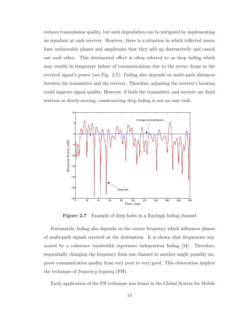
reduces transmission quality, but such degradation can be mitigated by implementing
an equalizer at each receiver. However, there is a situation in which reflected waves
have unfavorable phases and amplitudes that they add up destructively and cancel
out each other. This detrimental effect is often referred to as deep fading which
may results in temporary failure of communications due to the severe drops in the
received signal’s power (see Fig. 2.7). Fading also depends on multi-path distances
between the transmitter and the receiver. Therefore, adjusting the receiver’s location
could improve signal quality. However, if both the transmitter and receiver are fixed
stations or slowly-moving, counteracting deep fading is not an easy task.
0 20 40 60 80 100 120 140 160 180 200−30
−25
−20
−15
−10
−5
0
5
10
ReceivedPow
er(dB)
Time (ms)
Deep fade
Average recceived power
Figure 2.7 Example of deep fades in a Rayleigh fading channel
Fortunately, fading also depends on the carrier frequency which influences phases
of multi-path signals received at the destination. It is shown that frequencies sep-
arated by a coherence bandwidth experience independent fading [34]. Therefore,
sequentially changing the frequency from one channel to another might possibly im-
prove communication quality from very poor to very good. This observation inspires
the technique of frequency hopping (FH).
Early application of the FH technique was found in the Global System for Mobile
14
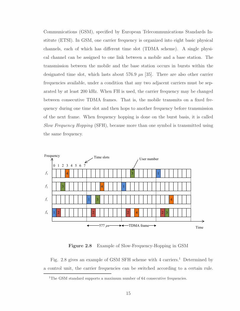
Communications (GSM), specified by European Telecommunications Standards In-
stitute (ETSI). In GSM, one carrier frequency is organized into eight basic physical
channels, each of which has different time slot (TDMA scheme). A single physi-
cal channel can be assigned to one link between a mobile and a base station. The
transmission between the mobile and the base station occurs in bursts within the
designated time slot, which lasts about 576.9 µs [35]. There are also other carrier
frequencies available, under a condition that any two adjacent carriers must be sep-
arated by at least 200 kHz. When FH is used, the carrier frequency may be changed
between consecutive TDMA frames. That is, the mobile transmits on a fixed fre-
quency during one time slot and then hops to another frequency before transmission
of the next frame. When frequency hopping is done on the burst basis, it is called
Slow Frequency Hopping (SFH), because more than one symbol is transmitted using
the same frequency.
1 2
3
4
4
1 3
2
3
1
2 4
0 1 2 3 4 5 6 7
Frequency
TimeTDMA frame
Time slots
577 µs
1
4
2 3
User number
1f
0f
2f
3f
Figure 2.8 Example of Slow-Frequency-Hopping in GSM
Fig. 2.8 gives an example of GSM SFH scheme with 4 carriers.1 Determined by
a control unit, the carrier frequencies can be switched according to a certain rule.
1The GSM standard supports a maximum number of 64 consecutive frequencies.
15

When the FH mode is deactivated, a mobile user only sends its data burst on one
carrier (for example, user 2 shown in Fig. 2.8). In the FH mode, the carrier frequency
keeps changing over individual TDMA frames in a pseudo-random manner. The pur-
poses are to provide frequency diversity and lower the overall likelihood of having
consecutive errors in deep fade situations. Another benefit of using a pseudo random
frequency hopping strategy is that it is possible to have multiple wireless links trans-
mitting autonomously on top of each other, provided that they use different random
key sequences and incorporate forward error correction so that the lost packets could
be reconstructed.
2.3 Fast Frequency Hopping and Non-coherent Detection
Extending the concept of FH, fast frequency hopping (FFH) was investigated
in [24], in which the carrier frequency is allowed to change more than once during
a symbol duration. However this technique was not widely implemented in civilian
applications at first. During the first and second World Wars, the FFH technique was
primarily used in military applications in order to secure the confidential information
and to make the system robust against jamming. Over the past few decades, FFH has
gained considerable interest due to its robustness in multiple access (MA) channel.
The first Frequency Hopping Multiple Access (FHMA) communication system was
proposed by Cooper and Nettleton in 1978 [36], which uses Differential Phase-Shift
Keying (DPSK) for wireless transmissions. In the following year, Viterbi introduced
the use ofM-ary Frequency Shift Keying (M-FSK) for low-rate multiple access mobile
satellite systems [37]. Since it enables non-coherent detection, theM-FSK modulation
has been widely adopted in Fast Frequency Hopping Multiple Access (FFH-MA)
systems. The FFH M-FSK technique is also adopted as the modulation scheme for
the relay systems considered in our research.
16

Bits to
symbols
Bits to
symbols
FH addressFH address
+ M-MM FSK
modudd lator
M-FSK
modulator
(1)s
(1)a
1st source1st source
(1)x
Bits to
symbols
Bits to
symbols
FH addressFH address
+ M-MM FSK
modud lator
M-FSK
modulator
( )ks
( )ka
ktkk htt sourcekth source
( )kx
. . .
. . .
. . .
1st transmiter
kth transmiter
+Fading effect +0
Noise
+Fading effect
DestinationDestination
MA channel
Figure 2.9 Structure of a FFH-MA communication system.
2.3.1 FFH-MA Communication System
Fig. 2.9 shows a FFH-MA system model, including multiple FFH-MFSK transmit-
ters. Each transmitted signal consists of L tones which are selected from M possible
frequencies. Assume there are K users in the system, who transmit their signals si-
multaneously. Without loss of generality, the transmission of a symbol from the kth
(1 ≤ k ≤ K) user is described. At first, the bit stream x(k) = [x(k)0 , x
(k)1 , . . . , x
(k)q−1] is
converted to a M-FSK symbol by grouping q = log2M information bits together:
s(k) =q−1∑
i=0
x(k)i 2i (2.1)
This M-FSK symbol determines which frequency tones the are activated. The symbol
transmission time Ts is divided into L time slots (also known as chip times), each of
which has duration Tc = Ts/L. To maintain orthogonality among FSK frequencies,
the minimum separation among any two adjacent frequency tones is 1/Tc. Therefore
the minimum bandwidth requirement for this system is M/Tc.
The challenging aspect of designing a FFH-MFSK system is to choose users’
unique frequency hopping addresses. Since multiuser signals are overlapped in both
17

time and frequency domains, their unique addresses are the key to distinguish one
signal from others. Specifically, each user needs to switch frequency after each chip
time and the next hop will be determined by its address code and transmitted symbol.
The address code a(k) =[
a(k)0 , a
(k)1 , . . . , a
(k)L−1
]
of the kth user has L components {a(k)l },
which belong to Galois Field GF(M). Then a(k) is combined with the transmitted
symbol s(k) to create time-frequency (TF) matrix S(k), which is used to decide which
frequency tone is activated at a particular chip time. The entries of matrix S(k) are
determined as
[
S(k)]
m,l≡ S
(k)m,l =
1, if s(k) ⊕ a(k)l = m
0, otherwise
, (2.2)
where m = 0, 1, . . . ,M − 1, l = 0, 1, . . . , L− 1 and ⊕ denotes addition in Galois Field
GF(M). Thus S(k)n is a binary matrix, whose columns correspond to chip times and
whose rows correspond to the sub-band frequencies.
All users transmit simultaneously to the destination over the same frequency band.
In general, the FH addresses of different users are not orthogonal, hence interference
among users exists. For example, it is always possible to have S(i)m,l = S
(j)m,l for certain
values of m and l with i 6= j. The amount of interference depends on how the FH
address codes are designed. The selection of the address code might be such that
the components of a(k) are chosen at random or according to some specific method.
Although randomly-generated FH addresses can be used, it is known that Einarsson’s
design method [38] minimizes the chance of having frequency collision among multiple
users. Extensive computer simulations in [39] have supported Einarsson’s proposal
and this method is still being considered as the optimum choice for generating FH
address codes.
Fig. 2.10 gives a visual illustration of different assignments of FH addresses and
their effects on transmission performance (in terms of diversity and interference).
In this example, the parameters M,L,K are set equal to 8, 4 and 2, respectively.
Comparison among 3 design methods are shown with their respective TF matrices.
Users’ transmitted symbols are s(1) = 2 and s(2) = 3. It is pointed out that in a
18

communication system, error rate is highly influenced by the worst case scenario.
Therefore only the most error-prone situation associated with each design is shown
in the figure. The following observations are made:
• In the “bad design”, a(1) = [1, 1, 2, 3] and a(2) = [0, 0, 0, 0]. It can be seen that
there are maximum two collisions that occur when two users send the same
frequency tones in the first two chip times. Signals from two users coming from
different paths might add up destructively and cause erasures (elimination of
signals at destination) or might add up constructively and generate a near-far
effect, which reduces the receiver’s performance.
Bad design Good design Excellent design
1
1
x x 2 2
0
1
2
3
4
5
6
7
1
1
1
2 x 2 2
0
1
2
3
4
5
6
7 1 2
2
2
1
x
1
0
1
2
3
4
5
6
7
1
2
User 1
User 2
x Collision
Figure 2.10 An example of different designs of frequency hopping addresses.
• In the “good design”, a(1) = [0, 1, 2, 3] and a(2) = [0, 0, 0, 0]. It is obvious that
the choice of FH addresses allows a maximum one frequency coincidence for
any given values of s(1) and s(2). However, signal from the second user does
not have frequency diversity and it occupies completely one sub-band during a
symbol transmission. Such a signal will suffer a severe degradation in a multi-
path fading channel. For the address scheme of the first user, its linear address
assignment is not good either. This is because the fading effect can spread over
several local consecutive frequencies. In fact, it is always better to spread the
19

user’s frequency tones over entire available bandwidth, i.e., keep them further
away from each other as much as possible.
• In the “excellent design”, a(1) = [6, 7, 5, 1] and a(2) = [5, 1, 2, 4] [38]. One can
see that not only the probability of collision is minimized (maximum 1 for 2
users, 2 for 3 users and so on), but also the time-frequency diversity is well
maintained among all users.
2.3.2 Conventional Detection of FFH Signals
M-MM FSK
demodud lator
M-FSK
demodulator
FH addressFH address
Maja ority
vote
Majority
vote
R
( )ka
( )ˆks
( )kD
Symbols to
bits
Symbols to
bits
Infor bits
FH addressFH address
Maja ority
vote
Majority
vote
(1)a
(1)s(1)D
Symbols to
bits
Symbols to
bits
Infor bits
Band pass
fiff lter
Band pass
filter
. . .
. . .
. . .
-
-
Figure 2.11 Conventional FFH detector.
The conventional FFH detector shown in Fig. 2.11 is also referred to as a majority
logic decoder [40], which can provide estimation for one or several desired users.
The front-end of such a detector contains a M-FSK demodulator, which reverses
the operation of the M-FSK modulator. Specifically, it contains a bank of M non-
coherent detectors (also known as energy detectors or squared-law detectors) that
tune to the M possible frequency tones. Each squared-law detector measures the
energy contains in one particular chip over the duration Tc. Each output is then
compared to a threshold (hard detected): if the output exceeds this threshold, the
20

detector output is 1, yielding a non-zero entry in the received observation matrix R.
Thus, R is a binary matrix with its TF locations marked “0” or “1” depending on
whether there is an user who activates that location or not. On a perfect channel
where neither noise nor fading is present, the “optimal” matrix R(opt) is obtained by
performing logical OR on all binary matrices {S(k)}Kk=1 :
[
R(opt)]
m,l≡ R
(opt)m,l =
K∨
k=1
S(k)m,l, (2.3)
where m = 0, 1, . . . ,M−1, l = 0, 1, . . . , L−1 and∨
denotes the logical OR operation.
In real transmission, false alarm occurs when a chip is not actually activated but the
noise level exceeds the decision threshold. On the other hand, there is also a possibility
of miss detection when the detected power drops below the threshold due to severe
fading or frequency conflict between two users. In general, the matrix R of M-FSK
demodulator might differ with the ideal result in (2.3) and the number of different
entries would depend on the channel condition.
The next step is to obtain the user-specific de-spreading matrix for symbol de-
tection of the desired user. Depending on each user’s unique FH address a(k), the
de-spreading matrix D(k) can be taken from the observation matrix as follows:
[
D(k)]
m,l≡ D
(k)m,l = Rm,l, (2.4)
where m = m ⊕ a(k)l . Then the majority vote is performed on D(k) to find symbol
s(k) that is most likely to be sent by the kth user. The rule to decide is: Choose the
codeword associated with the row containing the greatest number of entries [40].
Fig. 2.12 gives an illustration of de-spreading matrices in the detection process.
The parameters in this example are obtained from the excellent FH address design
mentioned on Page 20. In the figure, shaded boxes refer to locations that are marked
“1” in the associated binary TF matrix. As can be seen, noise and multi-path prop-
agation can influence the de-spreading matrices. While the symbol from user 1 is
detected correctly with one full row indicating s(1) = 2, detection of user 2 has an
ambiguity between s(2) = 3 and s(2) = 5, which is caused by energy deletion and
occurrence of the false alarm.
21

Legend
1 2
2
2
1
x
1
0
1
2
3
4
5
6
7
f
1 2
2
e
1
x
1 f
0
1
2
3
4
5
6
7
2
f
2
x 1 1 1
f0
1
2
3
4
5
6
7
1
f 1 f
x 2 2
10
1
2
3
4
5
6
7
Channel Despread
(opt )R R (1)
D
(2)D
1
2
User 1
User 2
x Collision
e Miss detection
f False alarm
Voted
symbol
Randomly
select
Figure 2.12 TF matrices at destination.
2.3.3 Joint Maximum Likelihood Detection
As the name suggests, this method jointly detects signals from all users at once
by measuring the coincidence among the received matrix R and candidate matrices
generated from a joint K-users symbol space [41]. Specifically, first it requires the
generation of s = [s(1), s(2), . . . , s(K)] that contains all distinct combinations of all K
users’ transmitted symbols. In total, there would be MK possibilities of choosing s.
For each possibility, Us is obtained by performing the logical OR over the distinct
combinations of all K users’ transmit matrices S(k):
[Us]m,l ≡ Us,m,l =K∨
k=1
S(k)m,l, given that s(k) = s(k), ∀k = 1, 2, . . . , K. (2.5)
Then a cost function is defined by counting the number of coinciding elements between
Us and R:
f(s) =M−1∑
m=0
L−1∑
l=0
Us,m,l ×Rm,l. (2.6)
22

Finally, the ML joint detection is performed by maximizing f(s) over all MK possible
patterns of s. Since MK is an extremely large number, even for a system with a
moderate number of users, the huge complexity of this method makes it impractical.
This difficulty motivates a low-complexity algorithm as discussed in the following
section.
2.3.4 Iterative Interference Cancellation (IIC)
While the idea of iterative cancellation of multi-user interference has widely been
applied to CDMA systems, there is little effort in applying IIC to FFH systems.
In 1996, Fiebig [42] first introduced a low-complexity algorithm for the joint detec-
tion of FFH signals in MA channels. The principle of the algorithm starts with the
conventional detection where symbol decisions are carried out if the corresponding
de-spreading matrices do not contain ambiguities. Taking into account these symbol
decisions, the corresponding entries in the received matrix R are canceled (erased)
and the conventional detection process is re-invoked based on a modified received ma-
trix. Then the process is iteratively carried out until either all symbols are estimated
or the last iteration does not yield a further symbol decision. Fiebig [42] provides
visual illustrations of this algorithm, and also derives a tight bound on the bit error
probability of this detection method.
Few years later, Fiebig and Roberson [43] proposed soft decoding for the FFH-
MFSK systems, which gives the opportunity to incorporate advanced channel en-
coders/ decoders. According to their research, although soft information is obtained
from the 2-level hard-limited received matrix R, their proposed soft-decoding method
gives a much better performance than using hard decoding. This idea is then ex-
panded by Park and Lee [44] by incorporating iterative decoding techniques to the
coded FFH-MFSK system in order to improve the channel capacity. They also con-
sider 3-level hard-limited decision instead of the conventional 2-level decision and
show that it helps improve the performance slightly.
However, the hard-limiting operation applied on the received signals is clearly
23

sub-optimal as it throws away part of the information delivered to the destination.
Inspired by the previous works and based on this observation, the next chapter pro-
poses and analyzes a novel IIC algorithm that makes full use of the received signals
at the destination.
24

3. Multi-User Relaying System with FFH
Modulation
3.1 Introduction
As discussed in Chapter 2, FFH modulation has many good features and has been
studied by many researchers (see, for example [25, 43, 45–49]). The main advantage
of FFH modulation is that it is highly tolerant to narrow-band interference as well as
burst noise. Using a relatively simple interference avoidance technique which provides
time-frequency diversity, an FFH system can share the same frequency band with
another system using different modulation type [50]. Such a feature also makes FFH
modulation technique suitable for MA communications. Furthermore, in combination
with non-coherent detection, the FFH demodulator can be strongly resistant to phase
noise and simple to implement. The analysis of FFH modulation in a MA system
was first performed in [40], which takes into account many factors such as bandwidth,
transmission rate, number of users, noise and interference issues. The authors also
proposed an optimal design under the assumption of random user address assignment.
Later on, Einarsson [38] investigated an optimal address assignment to minimize the
interference in a FFH-MA system. An upper bound on the bit error rate (BER)
versus the number of users in the system was also provided.
The existence of MAI, caused by the non-orthogonality of FH addresses, is an
inherent issue of an FFH-MA system. The MAI cannot be completely suppressed
by the receiver and is the main source of performance degradation. In general, the
level of MAI can be reduced by increasing the hopping rate at the expense of a
reduced data rate. Different approaches have also been developed to deal with the
25

MAI issue without sacrificing the data rate. One approach was initially presented
in [42] in which the author developed an iterative multiuser detector (MUD) that
exploits the prior knowledge of the FH addresses and energies of the user signals for
interference cancellation. Specifically, by taking into account the imbalance of the
instantaneous signal levels among multiple users, those signals with a better chance
of being detected correctly are decoded first and the results are used to remove the
ambiguity for detecting signals experiencing higher level of interference. This ideas
was later extended in [51] with the introduction of a multistage multiuser detector.
When channel coding is used, different strategies are investigated to deal with MAI
by incorporating the outputs of the channel decoders in the interference cancellation
process [44, 47, 52].
Most of research contributions in the area of FFH modulation focus on point-
to-point transmission, while only a few studies consider relay-assisted transmission
framework. Recently a multiuser relaying communication scheme based on FFH-MA
was presented in [29]. Making use of the half-duplex two-phase communication proto-
col, it was shown that a relay can help to improve the channel quality at the expense
of reducing the transmission rate by half. An optimal maximum-likelihood multiuser
detector (ML-MUD) was obtained and shown to achieve a good performance. How-
ever, the complexity of the ML-MUD grows exponentially with the number of users
and frequency tones [25], thus making it very expensive, if not impossible, for practical
implementation.
The system model presented in this chapter is similar to that in [29], i.e., it is con-
cerned with multiuser relaying with the help of a single relay. The difference is that,
while [29] only focuses on the demodulation of uncoded information transmission,
channel coding is considered in this thesis. By exploiting channel coding, an itera-
tive receiver is developed for both cases of AF relaying and PDAF relaying. In both
cases, the complexity of the iterative receiver is only proportional to the numbers of
users and frequency tones. The key operation of the developed receiver is to succes-
sively extract the maximum likelihood symbols of users and use that information for
26

interference cancellation. Simulation results demonstrate performance improvement
with iterations and the superiority of the proposed receiver when compared with the
detection method in [29] under the same spectral efficiency.
The rest of this chapter is organized as follows. Section 3.2 details the system
model under consideration. The calculations needed for interference cancellation in
the iterative receiver are provided in Section 3.3. Section 3.4 presents and discusses
simulation results.
3.2 System Model
Multiple access phase
Relaying/ broadcasting phase
S1
RS2
SK
D
..
.
S1
R
S2
SK
S3a) b)
...
Figure 3.1 Two models of relay networks: (a) Multiuser one-way relaying and (b)
Multiuser multi-way relaying.
Fig. 3.1-(a) illustrates a wireless network in which K users wish to send their in-
formation to a destination with the help of a relay. The relay operates in a half-duplex
mode, i.e., it can only transmit or receive at any given time. As such, transmission of
information from users to the destination happens in two phases. In the first phase,
all users send their information to the relay. The relay performs some form of signal
processing on the received signal before sending a new signal to the destination in
the second phase. Upon receiving the signal from the relay, the destination needs
to detect the information for all K users. Note that such a relay network is closely
related to the multi-way relaying considered in [29], which is depicted in Fig. 3.1-(b).
Compared to multiuser one-way relaying, the major difference of multiuser multi-way
27

relaying is that, instead of a single receiver, there are K receivers, one at each user
to detect information from the K − 1 other users. Naturally, the receiver developed
in this chapter for one-way relaying can be readily applied for each user in multi-way
relaying by subtracting out its own information.
3.2.1 Information Transmission of Users
Channel
encoder
Bits to
symbols
FH address
+MFSK
modulator
( )ˆ kv( )kv( )kx
kΠ
( )ks
( )ka
{ }( )
1
Nkn n=
S ( ) ( )kS t
...
from other users
Multiple access
Fading channel
kth transmitter
to relay
Figure 3.2 Structure of the kth user’s transmitter.
Fig. 3.2 illustrates the transmitter’s structure for the kth user. First, a vector
of Ni information bits, x(k), is encoded into a codeword v(k). An interleaver Πk,
specific to each user, is performed on v(k) to produce the interleaved codeword v(k).
The interleaved codeword v(k) is then modulated into a frame of N symbols, s(k) =
[s(k)0 , s
(k)1 , . . . , s
(k)N−1]. Here, N = NiRc
q, where Rc is the code rate and q = log2M is the
number of bits per M-ary frequency shift keying (M-FSK) symbol. For transmission
with FFH, the symbol period Ts is split into L chip times, each with a duration of
Tc = Ts/L. Each user is assigned a unique FH address, a(k) =[
a(k)0 , a
(k)1 , . . . , a
(k)L−1
]
.
For each symbol s(k)n , n = 0, 1, . . . , N − 1, a M × L time-frequency (TF) matrix S(k)
n
is formed to determine which frequency (i.e., sub-band) is activated at a particular
chip time. The entries of matrix S(k)n are determined as
[
S(k)n
]
m,l≡ S
(k)n,m,l =
1, if s(k)n ⊕ a
(k)l = m
0, otherwise
, (3.1)
where m = 0, 1, . . . ,M − 1, l = 0, 1, . . . , L− 1 and ⊕ denotes addition in Galois Field
GF(M). Thus S(k)n is a binary matrix, whose columns correspond to chip times and
whose rows correspond to the sub-band frequencies.
In the first phase, i.e., the multiple-access phase, all users transmit simultaneously
28

to the relay over the same frequency band. In general, the FH addresses of different
users are not orthogonal, hence interference among users exists. For example, it is
always possible to have S(i)n,m,l = S
(j)n,m,l for certain values of m and l with i 6= j. The
amount of interference depends on how the FH address codes are designed. Although
randomly-generated FH addresses can be used, it is known that Einarsson’s design
method [38] minimizes the chance of having frequency collision among multiple users.
This method shall also be used to assign FH addresses of users in this chapter.
The complex baseband-equivalent transmitted signal from the kth user over one
frame duration (i.e., N symbol durations) can be expressed as follows
S(k)(t) =
√
2Ec
Tc
N−1∑
n=0
L−1∑
l=0
exp(
j2πf(k)n,l t+ θ
(k)n,l
)
ψ(t− lTc − nTs), 0 ≤ t ≤ NTs, (3.2)
where Ec is the transmitted energy per chip, ψ(t) is a rectangular pulse shaping
function of unit amplitude over 0 ≤ t ≤ Tc and zero otherwise. The set of frequency
tones f(k)n,l is determined by the nonzero entries in S(k)
n . Since it is desired to maintain
the orthogonality across multiples tones within a chip time duration, two adjacent
sub-bands need to be separated by at least 1/Tc. Specifically, if S(k)n,m,l = 1, then the
frequency tone of the kth user during the interval lTc + nTs ≤ t < (l + 1)Tc + nTs
is f(k)n,l = m
Tc. Moreover, the phases of all the active carriers, θ
(k)n,l , are treated as
independent uniform random variables over (0, 2π). Note that the transmitted power
of the signal in (3.2) is P(k)tx = 2Ec/Tc.
With synchronous transmissions of all the users over the frequency-flat Rayleigh
fading channels, the complex baseband-equivalent signal received at the relay during
the MA phase can be written as follows:
R(t) =
√
2Ec
Tc
K∑
k=1
N−1∑
n=0
L−1∑
l=0
h(k)n,lψ(t− lTc − nTs) exp
(
j2πf(k)n,l t
)
+ w(t), 0 ≤ t ≤ NTs.
(3.3)
In (3.3), the phase term θ(k)n,l has been absorbed into the channel gain h
(k)n,l , which is
modeled as a zero-mean, unit-variance circularly-symmetric complex Gaussian ran-
dom variable, i.e., h(k)n,l ∼ CN (0, 1). Furthermore, h
(k)n,l are independent across users
and over different chip times [29]. The term w(t) is complex additive white Gaus-
29

sian noise (AWGN) with one-sided power spectrum density (PSD) N0 per dimention.
Note that, with the above signal model, the received signal-to-noise ratio (SNR) per
information bit is
γb =LEc
RcqN0. (3.4)
As mentioned before, after receiving R(t), the relay performs some form of signal
processing on R(t) to extract useful information, re-modulates and forwards a new
signal to the destination so that the destination can detect information bits of all K
users. The following subsections consider two relaying options, namely (i) amplify-
and-forward, and (ii) partially decode-and-forward.
3.2.2 Amplify-and-Forward Relaying
Baseband-
equivalent
fading channel
AF relay procesing
from MA
channel +
AWGN
+ (AF) ( )RS t( )R t
LPFLPF
(AF)b
to destination( )R t
Figure 3.3 Structure of AF relaying.
Fig. 3.3 shows the structure of amplify-and-forward relaying in complex baseband-
equivalent model. As the name suggests, the relay node simply filters and amplifies
the received signal in the first transmission phase and forwards the amplified version
to the destination in the second phase. The purpose of the low-pass filter (LPF) in
Fig. 3.3 is to limit the bandwidth of AWGN to the bandwidth of users’ transmitted
signals, which is approximately W = M/Tc. Let R(t) be the received signal after
the LPF. Then R(t) is composed of the same signal component, i.e., the first term in
(3.3), and the complex band-limited noise w(t), which has an average power of 2MN0
Tc.
Without loss of generality, let’s focus on the received signal at the relay over one
arbitrary chip duration in order to determine the amplification factor β(AF). Specifi-
30

cally, the received signal after the LPF during the lth chip interval of nth symbol can
be written as follows
Rn,l(t) =
√
2Ec
Tc
K∑
k=1
h(k)n,l exp(j2πf
(k)n,l )t+ w(t)
= Xn,l(t) + w(t), lTc + nTs ≤ t ≤ (l + 1)Tc + nTs,
(3.5)
where Xn,l(t) is the superimposed signal of all users. In order to maintain the trans-
mitted power of the relay to be P(R)tx , the value of β(AF) is:
β(AF) =
√
√
√
√
P(R)tx
P(R)rx + 2MN0/Tc
, (3.6)
where P (R)rx is the power of the signal portion received at the relay.
Under the assumption that all the channel gains are i.i.d. CN (0, 1), the quantity
P (R)rx is formally calculated as
P (R)rx = E
{h(k)n,l
}
{
1
Tc
∫ (l+1)Tc+nTs
lTc+nTs
|Xn,l(t)|2dt
}
= E{h
(k)n,l
}
2Ec
T 2c
∫ (l+1)Tc+nTs
lTc+nTs
∣
∣
∣
∣
∣
K∑
k=1
h(k)n,l exp(j2πf
(k)n,l t)
∣
∣
∣
∣
∣
2
dt
.
(3.7)
Note that with the FFH-MA scheme, there is a chance of having frequency collision,
i.e., f(i)n,l = f
(j)n,l , 1 ≤ i < j ≤ K. On the other hand, since different carrier frequencies
are made orthogonal over the chip interval Tc, all the cross-term components involving
two or more carrier frequencies in (3.7) would evaluate to zero. Let I and K denote
the sets of interfered users and non-interfered users, respectively, and let I[i] and K[i]
refer to the ith elements in these respective sets. It then follows that (3.7) can be
written as follows
P (R)rx =
2Ec
T 2c
E{h
(k)n,l
}
∣
∣
∣
∣
∣
I∑
i=1
h(I[i])n,l
∣
∣
∣
∣
∣
2∫ (l+1)Tc+nTs
lTc+nTs
∣
∣
∣ exp(j2πf(I[1])n,l t)
∣
∣
∣
2dt
+K−I∑
i=1
∣
∣
∣h(K[i])n,l
∣
∣
∣
2∫ (l+1)Tc+nTs
lTc+nTs
∣
∣
∣ exp(j2πf(K[i])n,l t)
∣
∣
∣
2dt
=2Ec
TcE{h
(k)n,l
}
∣
∣
∣
∣
∣
I∑
i=1
h(I[i])n,l
∣
∣
∣
∣
∣
2
+K−I∑
i=1
∣
∣
∣h(K[i])n,l
∣
∣
∣
2
=2KEc
Tc,
(3.8)
31

where I, 0 ≤ I ≤ K is number of elements in the set I. Substituting (3.8) into (3.6)
gives
β(AF) =
√
√
√
√
TcP(R)tx
2KEc + 2MN0. (3.9)
For the case that the power of the relay is constrained to be the sum of all transmitted
powers at the user nodes, i.e., P(R)tx = KP
(k)tx , one has β(AF) =
√
KEc
KEc+MN0.
Once β(AF) is determined, the relay transmits signal S(AF)R (t) = β(AF)R(t) to the
destination. The structure of the receiver at the destination is described in Section
3.2.4.
3.2.3 Partially Decode-and-Forward Relaying
from MA
channel
+
AWGN
LPFLPF
+
1
1exp( 2 )
2 c c
j f tE T
p-
+
+
...
Buffff eff r
length NLNN
Buffer
length NL
0
1exp( 2 )
2 c c
j f tE T
p-
1
1exp( 2 )
2 c c
Mj f tE T
p --
. |2| . |2
| . |2| . |2
| . |2| . |2
{ }1
N
n n=R
Threshold
detection
Threshold
detectionFSK
modud lator
MFSK
modulator
{ }1
N
n n=T (DF) ( )RS t
thl
( )R t
Energy detector
0(.)d
cT
tò
0(.)d
cT
tò
0(.)d
cT
tò
Figure 3.4 Structure of partial DF relaying.
As an alternative to the simple AF relaying, a partial DF relaying scheme is
proposed in Fig. 3.4, in which an energy detector and a FSK modulator are introduced
at the relay. The name “partial DF relaying” is used since the users’ information bits
are not fully decoded at the relay. The details of the partial DF relaying are described
next.
32

First, an LPF is applied to received signal R(t) in (3.3) to obtain band-limited
signal R(t). Over the nth symbol duration, n = 0, 1, . . . , N − 1, the relay performs
energy detection on R(t) to obtain a M × L normalized time-frequency matrix Rn.
The (m, l)th entry of Rn can be expressed as [29]
Rn,m,l =
∣
∣
∣
∣
∣
∣
1
Tc
∫ (l+1)Tc+nTs
lTc+nTs
R(t)√
2Ec/Tc
ψ(t− lTc − nTs) exp(−j2πfmt)dt
∣
∣
∣
∣
∣
∣
2
=
∣
∣
∣
∣
∣
K∑
k=1
h(k)n,l δ(f
(k)n,l − fm) + wn,m,l
∣
∣
∣
∣
∣
2
, (3.10)
where δ(·) is the Dirac delta function, defined as δ(0) = 1 and δ(x) = 0, ∀x 6= 0, and
wn,m,l is zero-mean complex AWGN component with variance σ2w = N0/Ec. Note that,
since h(k)n,l and wn,m,l are complex Gaussian random variables, it follows that Rn,m,l
obeys the exponential distribution with meanKn,m,l+σ2w, whereKn,m,l ∈ {0, 1, . . . , K}
is the number of users who activate the mth frequency tone during the lth chip time
of the nth symbol duration.
In preparation for information forwarding to the destination, the relay compares
the energy level at each TF location with a threshold λth to obtain a binary TF
matrix Tn. Thus, the (m, l)th entry of Tn is
Tn,m,l =
1, if Rn,m,l ≥ λth
0, otherwise
. (3.11)
The bits contained in matrix Tn are then sent to the destination to indicate which sub-
band was active in a given chip time of a symbol duration during the MA phase (which
could be due to one or multiple users). Using M-FSK modulation, the baseband-
equivalent signal transmitted by the relay over one frame duration (N symbols) can
be expressed as
S(DF)R (t) = β(DF)
√
2Ec
Tc
N−1∑
n=0
L−1∑
l=0
M−1∑
m=0
δ(Tn,m,l − 1)ψ(t− lTc − nTs) · exp (j2πfmt) ,
0 ≤ t ≤ NTs, (3.12)
where the amplification factor β(DF) is determined to maintain the relay’s transmitted
power to be P(R)tx .
33
In general, the value of β(DF) depends on system parameters K, M , L, as well
as the choice of threshold λth at the relay. It is obvious that if λth is increased, the
number of locations with value 1 in Tn reduces, hence more transmit power is spent
on each activated chip duration. Assuming that the values of the TF matrix Tn are
independent, the average transmitted power at the relay can be obtained as follows:
P(R)tx = E
{
1
NTs
∫ NTs
0
∣
∣
∣S(DF)R (t)
∣
∣
∣
2dt
}
= E
{
(
β(DF))2 2Ec
Tc
1
NL
N−1∑
n=0
L−1∑
l=0
M−1∑
m=0
δ(Tn,m,l − 1)
}
(3.13)
=(
β(DF))2 2MEc
Tc
P (Tn,m,l = 1)
=(
β(DF))2 2MEc
Tc
P (Rn,m,l ≥ λth).
Recall that Rn,m,l has an exponential distribution with a mean value determined by
the number of users who activate the mth frequency tone. For a given chip duration,
there are total K users; each of which can activate a particular frequency tone with
equal probability 1/M . Therefore, by applying the law of total probability, one has
P (Rn,m,l ≥ λth) =K∑
k=0
P (Rn,m,l ≥ λth|Kn,m,l = k)P (Kn,m,l = k)
=K∑
k=0
exp
(
−λth
k + σ2w
)
B(K, k, 1/M), (3.14)
where B(·) is a binomial distribution, given as
B(K, k, 1/M) =
(
K
k
)
1
Mk
(
1 −1
M
)(K−k)
. (3.15)
Finally, substituting (3.14) into (3.13) gives
β(DF) =
√
√
√
√
√
√
TcP(R)tx
2MEc∑K
k=0 exp(
− λth
k+σ2w
)
B(K, k, 1/M). (3.16)
Before closing this section, it is relevant to discuss the choice of threshold λth used
at the partial DF relay. First, consider the case of no interference (i.e., Kn,m,l = 0
or 1). In this situation, each entry Rn,m,l has an exponential distribution with mean
value of (1 + σ2w) or σ2
w, depending on whether there is a signal component at the
34

(m, l)th location. The error probability of the squared-law detector using threshold
λth is
Pe =1
2P (error|Kn,m,l = 0) +
1
2P (error|Kn,m,l = 1)
=1
2exp
(
−λth
σ2w
)
+1
2
[
1 − exp
(
−λth
1 + σ2w
)]
.(3.17)
It is simple to see that the threshold that minimizes Pe is
λth = σ2w(1 + σ2
w) ln
(
1 + σ2w
σ2w
)
. (3.18)
Now, using the above threshold for the general case (i.e., with multiuser interfer-
ence), it is readily seen that
P (Rn,m,l ≥ λth|Kn,m,l) = exp
(
−λth
Kn,m,l + σ2w
)
. (3.19)
Obviously,
P (Rn,m,l ≥ λth|Kn,m,l = 1) < P (Rn,m,l ≥ λth|Kn,m,l > 1) .
Thus, having two or more users transmitting in one chip time is more likely to yield
a nonzero entry in Tn. In general, there is an optimal threshold for each set of
system parameters M,K,L, σ2w, which can be found by simulation [29]. However the
sub-optimal threshold in (3.18) is more computation-friendly, while providing good
performance. As such the threshold in (3.18) is also used in this chapter.
3.2.4 Receiver at the Destination
The general structure of the proposed receiver at the destination is shown in Fig.
3.5, which applies to both the AF and partial DF relaying schemes. Such a receiver
makes use of the iterative (i.e., turbo) signal processing technique to handle the multi-
user interference. The iteration is between the channel decoders and the interference
cancellers.
Let Y (t) be the complex baseband-equivalent received signal at the destination
over one frame duration, i.e., 0 ≤ t ≤ NTs. The front-end of the receiver first
35

Energy
detector
Energy
detector
axMax
Interfeff rence
canceller
Interference
cancellerSISO
decoder
SISO
decoder
information
bits
Symbol
likelihood
Symbol
likelihood...
From other
detectors
Bit LLR
calculation
Bit LLR
calculation
kth detector
( )Y t ( )
,( )k
n jbL
( )
,( )k
n jcLBits to symbol
mapaa per
Bits to symbol
mapper
[ 1] ( ) [ ]( | , )k
nn nL sn n+Y U
a(k)
( )
,( )k
n icL
{ }1
N
n n=Y
[ ]
n
nU
( )ˆ( )k
nL s
Feedbdd ack
upuu dating
Feedback
updating
( )
,( )k
n ibL
kP
1
k
-P
Figure 3.5 Structure of the receiver at the destination.
performs energy detection in the same way as what done in the relay (see Fig. 3.4)
to obtain a set of normalized observation matrices Y = {Y1,Y2, . . . ,YN}. Next,
the set Y is fed to a bank of K parallel detectors. Each detector is responsible for
the decoding of one user. It is pointed out that the interference canceller tries to
remove one interferer’s signal after each iteration. Therefore the maximum number
of iterations is equal to number of concurrent users in the system. Without loss of
generality, the main operations of the kth detector are described next.
In each iteration, the interference cancellation block carries out its computations
on symbol-by-symbol basis. For the nth symbol duration, it makes use of the obser-
vation matrix Yn together with the feedback information from the previous iteration
to generate the probabilities (or likelihood values) for the nth symbol of the kth user.
Let U[ν]n be the M × L matrix that contains the feedback information from the νth
iteration. Then the output of the kth interference canceller at the (ν + 1)th iteration
is denoted by P [ν+1](s(k)n |Yn,U
[ν]n ). Applying Bayes’ theorem gives
P [ν+1](s(k)n |Yn,U
[ν]n ) =
p(Yn|s(k)n ,U[ν]
n )P (s(k)n )
∑M−1s=0 p(Yn|s,U
[ν]n )P (s)
. (3.20)
Under the assumption that all the entries of Yn are independent random variables,
one has
p(Yn|s(k)n ,U[ν]
n ) =M−1∏
m=0
L−1∏
l=0
p(Yn,m,l|s(k)n , U
[ν]n,m,l). (3.21)
36

The computation of (3.21) depends on whether the AF or partial DF relaying is used.
This computation is presented in detail in Section 3.3.
After each iteration of the whole receiver, the kth detector gives out N sets of
soft likelihood values, one set having M values for each of the kth user’s symbols.
The feedback information is updated at the end of the νth iteration as follows. Over
the nth symbol duration, the soft values of the K − ν + 1 users (i.e., detectors)
who have not been decoded in any of the previous iterations are compared and the
most likelihood symbol together with the user it belongs to are decided. That is, the
additional feedback information over the nth symbol duration at the end of the νth
iteration is of the form s(vn)n for some user index vn. The update of the information
feedback matrix, U[ν]n , is
U[ν]n,m,l =
U([ν−1])n,m,l + 1, if s(vn)
n ⊕ a(vn)l = m
U([ν−1])n,m,l , otherwise
. (3.22)
Therefore, at the beginning of the (ν+1)th iteration, individual locations of feedback
matrix U[ν]n take on values in the set {0, 1, . . . , ν− 1}. The exact value gives valuable
information on how many users transmit over a specific time-frequency location. Such
information is used by the interference canceller to refine the computation of the
symbol likelihood values in the next iteration. It should also be noted that in the
first iteration (ν = 1), no feedback information is available, hence U[0]n = 0.
The symbol likelihood values are then converted to the bit log-likelihood ratios
(LLRs) so that they can be used by the SISO channel decoder. Let b(k)n,j denote the
bit at the jth position of symbol s(k)n . Considering the binary to M-ary mapping rule
b(k)n,j = (s(k)
n 2−j) mod 2, j = 0, 1, . . . , q − 1, one has
P (b(k)n,j = 0|Yn,U
[ν]n ) =
M−1∑
s=0
δ
(
s
2jmod 2
)
P (s|Yn,U[ν]n )
=M/2−1∑
r=0
P(
r +⌊
r
2j
⌋
2j
∣
∣
∣
∣
Yn,U[ν]n
)
, (3.23)
where ⌊·⌋ denotes the truncation function. Furthermore, the bit LLR can be written
37
as
Λ(b(k)n,j) = ln
P (b(k)n,j = 1|Yn,U
[ν]n )
P (b(k)n,j = 0|Yn,U
[ν]n )
= ln
1 − P (b(k)n,j = 0|Yn,U
[ν]n )
P (b(k)n,j = 0|Yn,U
[ν]n )
. (3.24)
After being de-interleaved, Λ(b(k)n,j) becomes the a priori LLR, Λ(b
(k)n,i), which can
be used as the soft input for the SISO channel decoder. The decoder then computes
the a posteriori LLR Λ(c(k)n,i) for each coded bit. That information is then interleaved
and used to compute the log-likelihood values of the decoded symbol, L(s(k)n ). By the
definition of Λ(c(k)n,i) and the mapping between c
(k)n,j and s(k)
n , one has
Λ(c(k)n,j) = ln
P (c(k)n,j = 1)
P (c(k)n,j = 0)
= ln
P (c(k)n,j = 1)
1 − P (c(k)n,j = 1)
= ln
P(
c(k)n,j = s
(k)n
2j mod 2)
1 − P(
c(k)n,j = s
(k)n
2j mod 2)
, j = 0, 1, . . . , q − 1. (3.25)
Under the assumption that the bits associated with a given symbol are independent,
the log-likelihood values of a detected symbol can be computed from the LLR values
of the coded bits as
L(s(k)n ) =
q−1∑
j=0
L(s(k)n |c(k)
n,j) =q−1∑
j=0
L
(
c(k)n,j =
s(k)n
2jmod 2
)
=q−1∑
j=0
(∣
∣
∣Λ(c(k)n,j)
∣
∣
∣− ln(
1 + exp(∣
∣
∣Λ(c(k)n,j)
∣
∣
∣
)))
. (3.26)
The above outputs of the K detectors are used in the interference cancellers as
follows. After each decoding stage, the output of one detector consists of N hard-
decision symbols, s(k) = [s(k)1 , s
(k)2 , . . . , s
(k)N ], together with their log-likelihood values
[L(s(k)1 ), L(s
(k)2 ), . . . , L(s
(k)N )]. The “Max” module compares these outputs from all the
detectors to find one set of the N most reliable detected symbols as:
s(vn)n = argmax
vn∈K[ν]n
{
L(s(vn)n )
}
, n = 1, 2, . . . , N, (3.27)
where the maximization is over the set of users whose nth symbols have not been
detected in the (ν − 1) previous decoding stages, denoted as K[ν]n . The symbols
38

System Parameters
M = 8, L = 4, K = 3, N = 5
a(1)=[1,2,4,3]
a(2)=[3,6,7,5]
a(3)=[5,1,2,4]
6 2 2 7 5
-0.6116 -1.2257 -0.0034 -0.6375 -0.5827
4 5 5 7 1
-0.0003 -1.0955 -0.2982 -0.4408 -0.0001
7 3 2 6 2
-0.2049 -0.0668 -0.0006 -0.5162 -0.0347
2 2 2 5 5
-0.0104 -0.2011 -0.0003 -0.3838 -0.5540
4 3 0 7 1
-0.0003 -0.5519 -0.0443 -0.0448 -0.0001
7 3 2 7 0
-0.0269 -0.0668 -0.0006 -0.0007 -0.5975
2 2 2 5 5
-0.0104 -0.2011 -0.0003 -0.0801 -0.5540
4 7 0 7 1
-0.0003 -0.206 -0.0007 -0.0448 -0.0001
7 3 2 7 2
-0.0021 -0.0668 -0.0006 -0.0007 -0.0047
5 Symbol #
Detector #1 2
2n
d i
tera
tion
3rd
ite
rati
on
3 4
1st
ite
rati
on
(1)s
(1)ˆ( )L s(2)s
(2)ˆ( )L s(3)s
(3)ˆ( )L s(1)s
(1)ˆ( )L s(2)s
(2)ˆ( )L s(3)s
(3)ˆ( )L s(1)s
(1)ˆ( )L s(2)s
(2)ˆ( )L s(3)s
(3)ˆ( )L s
Symbols decoded at 1st iteration
Symbols decoded at 2nd iteration
Symbols decoded at 3rd iteration
Symbols get fixed at later iteration
(a)
Ts = LTc
Frame time
Fre
qu
ency
To
nes
0
1
2
3
4
5
6
7
Last symbol of
frame
[2]
3U[2]
1U
[3]
1U[3]
3U[3]
5U
1
1
1
1
1
1
1
1 1
1
1
1
1
1
1
1 1
1
1
1
1
1
1
1
1
2
1
1 1
1
1
1
1
1
1
1 1
2
1
1
1
1
1
1
1
1
1
1
1
1
1
1
1
1
1
1
1
1
Fre
qu
ency
To
nes
0
1
2
3
4
5
6
7
(b)
Figure 3.6 Example illustrating the proposed iterative receiver: (a) Hard and soft
outputs after each iteration, (b) Updating process of feedback matrix
U[ν]n .
39

{s(vn)n }N
n=1 are then used to update matrix U[ν]n as in (3.22), while the log-likelihood
values {L(s(vn)n )}N
n=1 remain unchanged for the next iteration.
A simple example to illustrate how the proposed iterative receiver works is pro-
vided in Fig. 3.6 where the symbol likelihood values are shown. For this example,
there are K = 3 users communicating to a destination using M = 8 frequency tones
and L = 4 chip times. The frame length is taken to be N = 5, while the users’ FH
addresses are indicated in the figure. Focusing on the first symbol duration, given the
numerical values provided in the figure, it can be readily seen that K[1]1 = {1, 2, 3},
K[2]1 = {1, 3} and K
[3]1 = {3}.
3.3 Interference Cancellation
This section examines in more detail the operation of the interference cancellation
blocks in the iterative receiver. As pointed out before, the main task of this block
is to compute (3.20), which is required in order to calculate p(Yn,m,l|s(k)n , U
[ν]n,m,l) for
(3.21).
3.3.1 AF Relaying
When AF is used at the relay, the received complex baseband equivalent signal at
the destination over the lth chip interval of nth symbol can be written as
Yn,l(t) = β(AF)gn,lRn,l(t) + η(t) = β(AF)gn,l (Xn,l(t) + w(t)) + η(t), (3.28)
where the coefficient gn,l ∼ CN (0, 1) represents the effect of the flat-fading channel
between the relay and the destination and η(t) is complex AWGN at the destination,
whose one-sided power spectral density is N0 per dimension. As in the MA phase,
gn,l’s are assumed to be independent over different chip durations [29].
With the above input signal, the normalized output of the energy detector can be
40
computed as Yn,m,l = |yn,m,l|2, where
yn,m,l =1
Tc
∫ (l+1)Tc+nTs
lTc+nTs
Yn,l(t)
β(AF)√
2Ec/Tc
ψ(t− lTc − nTs) exp(−j2πfmt)dt
= gn,l
(
K∑
i=1
h(i)n,lδ(f
(i)n,l − fm) + wn,m,l
)
+ ηn,m,l.
(3.29)
In (3.29), the noise terms wn,m,l and ηn,m,l are zero-mean circularly-symmetric complex
Gaussian random variables with variances σ2w = N0/Ec and σ2
η = N0/(β(AF))2Ec,
respectively.
As shall be seen later, to calculate p(Yn,m,l|s(k)n , U
[ν]n,m,l), it is useful to determine
the distribution of yn,m,l given that there are k users who concurrently transmit with
the same carrier frequency fm during the time slot lTc + nTs < t < (l + 1)Tc + nTs.
Denote this distribution as p(yn,m,l|k). Given k, the first term in (3.29), namely
xn,m,l =(
∑Ki=1 h
(i)n,lδ(f
(i)n,l − fm) + wn,m,l
)
, is a complex Gaussian random variable of
zero-mean and variance σ2x = k + σ2
w. Using the distribution of a product of two
independent complex Gaussian random variables in [53], the pdf of yn,m,l conditioned
on k and ηn,m,l is
p(yn,m,l|k, ηn,m,l) =2
π(k + σ2w)K0
2|yn,m,l − ηn,m,l|√
k + σ2w
, (3.30)
where K0(·) is the zero-order modified Bessel function of the second kind.
In order to obtain p(yn,m,l|k), one has to take the expectation of (3.30) over ηn,m,l.
Unfortunately, there is no closed-form expression for such expectation. To overcome
this difficulty, the following approximation, similar to what used in [53], is proposed:
p(yn,m,l|k) ∼2
π(k + σ2w)K0
2√
k + σ2w
√
|yn,m,l|2 + σ2η
. (3.31)
Correspondingly, the following approximation is used for p(Yn,m,l|k):
p(Yn,m,l|k) ∼2
π(k + σ2w)K0
2√
k + σ2w
√
Yn,m,l + σ2η
. (3.32)
41

Next, the pdf p(Yn,m,l|s(k)n , U
[ν]n,m,l) is calculated as follows:
p(Yn,m,l|s(k)n , U
[ν]n,m,l) = p(Yn,m,l|U
[ν]n,m,l, S
(k)n,m,l = 1) · P (S
(k)n,m,l = 1|s(k)
n )
+ p(Yn,m,l|U[ν]n,m,l, S
(k)n,m,l = 0) · P (S
(k)n,m,l = 0|s(k)
n ). (3.33)
Since all the K users transmit their signals simultaneously in the MA phase, there
exists interference from a number of users at each chip time. At the νth iteration,
there are (ν− 1) symbols decoded over each symbol duration that are determined for
(ν − 1) users in the previous iterations. The symbol information from other (K − ν)
users remains unknown and should be treated as interference. After each iteration, one
more symbol is decoded and the number of interferers reduces by one. Specifically,
the distribution of Yn,m,l at a single TF location depends on three factors: (i) the
transmitted symbol s(k)n , (ii) the ν − 1 decoded symbols from previous iterations,
which can be seen from U[ν−1]n,m,l , and (iii) the random interference from the remaining
K − ν users.
Let J , 0 ≤ J ≤ (K−ν), be the number of interferers in one particular TF location.
Then one has
p(Yn,m,l|U[ν]n,m,l, S
(k)n,m,l = 1) =
K−ν∑
j=0
p(Yn,m,l|U[ν]n,m,l, S
(k)n,m,l = 1, J = j)P (J = j). (3.34)
As pointed out before, the probability P (J = j) is determined by the binomial dis-
tribution B(K − ν, j, 1/M). On the other hand, p(Yn,m,l|U[ν]n,m,l, S
(k)n,m,l = 1, J = j) is
concerned with the distribution of the energy measured at the (n,m, l) TF location
under the hypothesis that there are U[ν]n,m,l decoded users (coming from the feedback
information), one user of interest and j interferers who are active in that TF location.
It then follows from (3.32) that
p(Yn,m,l|U[ν]n,m,l, S
(k)n,m,l = 1, J = j) =
2
π(U[ν]n,m,l + 1 + j + σ2
w)K0
2
√
√
√
√
Yn,m,l + σ2η
(U[ν]n,m,l + 1 + j + σ2
w)
.
(3.35)
Substituting (3.35) into (3.34) yields
p(Yn,m,l|U[ν]n,m,l, S
(k)n,m,l = 1) =
K−ν∑
j=0
2B(K − ν, j, 1/M)
π(U[ν]n,m,l + 1 + j + σ2
w)K0
2
√
√
√
√
Yn,m,l + σ2η
(U[ν]n,m,l + 1 + j + σ2
w)
.
(3.36)
42

Similarly, one has
p(Yn,m,l|U[ν]n,m,l, S
(k)n,m,l = 0) =
K−ν∑
j=0
2B(K − ν, j, 1/M)
π(U[ν]n,m,l + j + σ2
w)K0
2
√
√
√
√
Yn,m,l + σ2η
(U[ν]n,m,l + j + σ2
w)
.
(3.37)
Then substituting the two above equations into (3.33) gives
p(Yn,m,l|s(k)n , U
[ν]n,m,l) =
P (S(k)n,m,l = 1|s(k)
n ) ·K−ν∑
j=0
2B(K − ν, j, 1/M)
π(U[ν]n,m,l + 1 + j + σ2
w)K0
2
√
√
√
√
Yn,m,l + σ2η
(U[ν]n,m,l + 1 + J + σ2
w)
+ P (S(k)n,m,l = 0|s(k)
n ) ·K−ν∑
j=0
2B(K − ν, j, 1/M)
π(U[ν]n,m,l + j + σ2
w)K0
2
√
√
√
√
Yn,m,l + σ2η
(U[ν]n,m,l + j + σ2
w)
. (3.38)
In the above expression, the quantity P (S(k)n,m,l = 1|s(k)
n ) = 1 − P (S(k)n,m,l = 0|s(k)
n ) is
determined by the M-FSK mapping rule. It takes on a value of 1 or 0 depending on
the FH address a(k) of the kth user and the transmitted symbol s(k)n .
It should also be pointed out that, although the AF is a simple operation at the
relay, the computing of p(Yn,m,l|s(k)n , U
[ν]n,m,l) in (3.38) is quite complicated due to the
presence of the modified Bessel function. In practical implementation, one would
pre-compute the modified Bessel function for a large set of its argument, store the
values in the read-only memory (ROM) and use them to approximate the true values.
3.3.2 Partial DF Relaying
For the case of partial DF relaying, the received complex baseband-equivalent
signal at the destination is given as
Y (t) = β(DF)
√
2Ec
Tc
N−1∑
n=0
L−1∑
l=0
gn,l
(
M−1∑
m=0
δ(Tn,m,l−1)ψ(t−lTc−nTs) exp (j2πfmt)
)
+η(t),
0 ≤ t ≤ NTs. (3.39)
The normalized output of the energy detector is
Yn,m,l =
∣
∣
∣
∣
∣
∣
1
Tc
∫ (l+1)Tc+nTs
lTc+nTs
Y (t)
β(DF)√
2Ec/Tc
ψ(t− lTc − nTs) exp(−j2πfmt)dt
∣
∣
∣
∣
∣
∣
2
=∣
∣
∣
∣
gn,l · δ(Tn,m,l − 1) + ηn,m,l
∣
∣
∣
∣
2
. (3.40)
43

As in the AF relaying case, the noise term ηn,m,l is a zero-mean circularly-symmetric
complex Gaussian random variable with variance σ2η = N0/(β
(DF))2Ec. It can be seen
that Yn,m,l is an exponential variable, whose mean value is either (1+σ2η) if its location
corresponds to a nonzero signal transmitted by the relay, or σ2η otherwise.
Finding the expression of p(Yn,m,l|s(k)n , U
[ν]n,m,l) can be done by taking into account
the decision made at the relay. Specifically, one has
p(Yn,m,l|s(k)n , U
[ν]n,m,l) = p(Yn,m,l|Tn,m,l = 1) · P (Tn,m,l = 1|s(k)
n , U[ν]n,m,l)
+ p(Yn,m,l|Tn,m,l = 0) · P (Tn,m,l = 0|s(k)n , U
[ν]n,m,l). (3.41)
It follows from (3.40) that
p(Yn,m,l|Tn,m,l = 1) =1
1 + σ2η
exp
(
−Yn,m,l
1 + σ2η
)
, (3.42)
and
p(Yn,m,l|Tn,m,l = 0) =1
σ2η
exp
(
−Yn,m,l
σ2η
)
. (3.43)
On the other hand, since Tn is obtained by comparing the entries of Rn with threshold
λth as in (3.11), one has
P (Tn,m,l = 0|s(k)n , U
[ν]n,m,l) = 1 − P (Tn,m,l = 1|s(k)
n , U[ν]n,m,l) = P (Rn,m,l < λth|s
(k)n , U
[ν]n,m,l).
(3.44)
To determine the probability P (Rn,m,l < λth|s(k)n , U
[ν]n,m,l), the conditional pdf of
Rn,m,l is needed. It is computed as follows:
p(Rn,m,l|s(k)n , U
[ν]n,m,l) = p(Rn,m,l|U
[ν]n,m,l, S
(k)n,m,l = 1) · P (S
(k)n,m,l = 1|s(k)
n )
+ p(Rn,m,l|U[ν]n,m,l, S
(k)n,m,l = 0) · P (S
(k)n,m,l = 0|s(k)
n ), (3.45)
where, similar to the expression in (3.38) for the case of AF relaying, the two prob-
abilities P (S(k)n,m,l = 1|s(k)
n ) and P (S(k)n,m,l = 0|s(k)
n ) take on a value of 1 or 0 depending
on the FH address a(k) of the kth user and the transmitted symbol s(k)n . Also, similar
to the calculation of p(Yn,m,l|U[ν]n,m,l, S
(k)n,m,l = 1) in (3.34), the conditional densities
p(Rn,m,l|U[ν]n,m,l, S
(k)n,m,l = 1) and p(Rn,m,l|U
[ν]n,m,l, S
(k)n,m,l = 0) can be found by considering
44

the number of unknown interferers at the νth iteration, which can take any value
between 0 and (K − ν). Specifically,
p(Rn,m,l|U[ν]n,m,l, S
(k)n,m,l = 1) =
K−ν∑
j=0
p(Rn,m,l|U[ν]n,m,l, S
(k)n,m,l = 1, J = j) · P (J = j)
=K−ν∑
j=0
B(K − ν, j, 1/M)
U[ν]n,m,l + 1 + j + σ2
w
exp
−Rn,m,l
U[ν]n,m,l + 1 + j + σ2
w
, (3.46)
and
p(Rn,m,l|U[ν]n,m,l, S
(k)n,m,l = 0) =
K−ν∑
j=0
B(K − ν, j, 1/M)
U[ν]n,m,l + j + σ2
w
exp
−Rn,m,l
U[ν]n,m,l + j + σ2
w
.
(3.47)
Finally, by substituting (3.47) and (3.46) into (3.45) and performing integration,
one obtains:
P (Tn,m,l = 0|s(k)n , U
[ν]n,m,l) =
P (S(k)n,m,l = 1|s(k)
n )K−ν∑
j=0
B(K − ν, j, 1/M)
U[ν]n,m,l + 1 + j + σ2
w
∫ λth
0exp
−x
U[ν]n,m,l + 1 + j + σ2
w
dx
+(
1 − P (S(k)n,m,l = 1|s(k)
n ))
K−ν∑
j=0
B(K − ν, j, 1/M)
U[ν]n,m,l + j + σ2
w
∫ λth
0exp
−x
U[ν]n,m,l + j + σ2
w
dx
=K−ν∑
j=0
B(K − ν, j, 1/M)
1 − exp
−λth
U[ν]n,m,l + j + σ2
w
+ P (S(k)n,m,l = 1|s(k)
n )×
K−ν∑
j=0
B(K − ν, j, 1/M)
exp
−λth
U[ν]n,m,l + j + σ2
w
− exp
−λth
U[ν]n,m,l + 1 + j + σ2
w
.
(3.48)
It should be pointed out that, for fixed parametersM,K, λth, the above probability
can be computed once at the beginning of each iteration. Moreover, since P (S(k)n,m,l =
1|s(k)n ) is 0 or 1 and U
[ν]n,m,l takes on integer values ranging from 0 to (ν − 1), at the
νth iteration one can pre-compute and store 2ν quantities instead of repeating the
calculation for every (m, l) location.
To avoid the numerical instability issue in implementation, instead of computing
the probability values P (s(k)n |Yn,U
[ν]n ), it is possible to perform all the related calcula-
45

tions in the log-domain and compute the L-values L(s(k)n |Yn,U
[ν]n ) = lnP (s(k)
n |Yn,U[ν]n ).
The details are given in Appendix A.
3.4 Simulation Results
This section presents the simulation results of the bit-error-rate (BER) perfor-
mance of the proposed multiuser relaying system. All simulations are done in MAT-
LAB. First, a constraint-length 7, rate−1/2 convolutional code with generator poly-
nomials g(0) = [2, 4, 7] and g(1) = [3, 7, 1] (in octal form) is employed. This is the best
convolutional code for given constraint length and code rate and its free Euclidean
distance is dfree = 10 [54]. The information block length is set to be 1920 bits. Thus,
for a system with M = 16 or M = 32 frequency tones, one code block contains 480
or 384 M-FSK symbols, respectively. Each user is assigned a different S-random in-
terleaver with the spreading factor of 25. The power allocated for the relay is set to
be P(R)tx = KP
(k)tx . This setup results in the same average SNR in all transmission
links, i.e., from users to relay, and from relay to destination. The SNR shown in all
figures of this section is the average SNR per information bit, given as in (3.4). On
the other hand, given similar channel conditions experienced by each user, all users
are expected to have similar BER performance and the BER curves plotted in all
figures are averaged over all users.1 Also note that since the use of coding reduces the
transmission rate, in order to have a fair comparison (in terms of spectral efficiency)
with the uncoded transmission in [29], our system only uses half the number of chip
times that would be used in the uncoded system. The spectral efficiency is measured
as µ = RcK log2(M)LM
(bit/s/Hz).
First, the performance of the AF relaying system is shown in Fig. 3.7 for system
parameters of M = 16, K = 5 and L = 4. It can be seen that remarkable performance
improvements with iterations of the proposed receiver are achieved. Moreover, the
proposed system (with channel coding) is able to provide a huge performance boost
over the uncoded system (which uses L = 8) that employs the maximum-likelihood
1When plotted separately, the BER curves of individual users essentially overlap each other.
46

multiuser detection (MUD) as studied in [29].
12 13 14 15 16 17 1810
−5
10−4
10−3
10−2
10−1
100
Biterrorrate
γb (dB)
1st iteration
2nd iteration
3rd iteration
4th iteration
5th iterationML−MUD (uncoded)
Figure 3.7 BER performance of the AF relaying system with M = 16.
Of particular interest is the performance of the proposed partial DF relaying
system, which is shown in Fig. 3.8 for a system configured with M = 16, K = 5 and
L = 4, and in Fig. 3.9 for a system with M = 32, K = 6 and L = 3. Note that the
spectral efficiency of these two systems is µ = 0.1563 (bit/s/Hz). Compared to Fig.
3.7, Fig. 3.8 clearly shows that the proposed partial DF relaying outperforms the AF
relaying. At the last stage of decoding, the proposed partial DF relaying achieves a
coding gain of 3.5dB2 (measured at the BER level of 10−4) when compared to the
performance of the first-state decoding (i.e., decoding with no feedback for interference
cancellation) and 6.5dB better than the uncoded system using the optimal ML-MUD.
However, there is about 2dB gap when compared to the single-user performance (i.e.,
2As 3dB means two times in linear scale, a 3.5dB of coding gain can help to reduce the transmitted
power by about 55 percent.
47
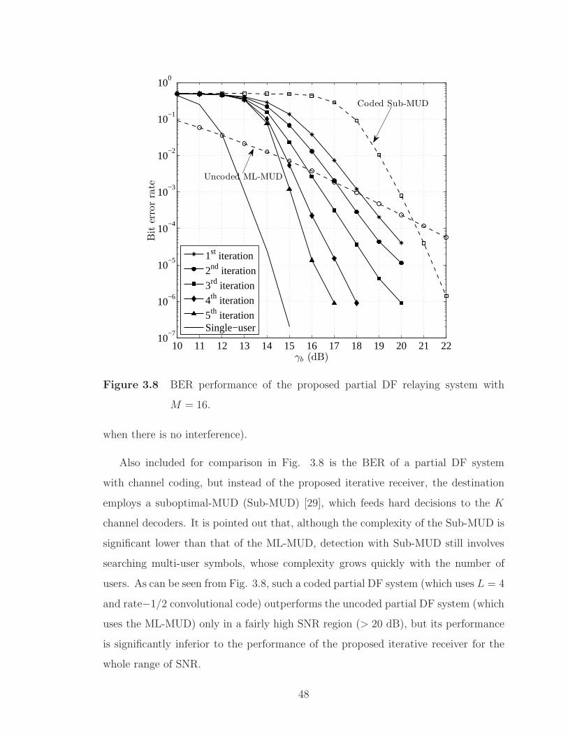
10 11 12 13 14 15 16 17 18 19 20 21 2210
−7
10−6
10−5
10−4
10−3
10−2
10−1
100
γb (dB)
Biterrorrate
1st iteration
2nd iteration
3rd iteration
4th iteration
5th iterationSingle−user
Coded Sub-MUD
Uncoded ML-MUD
Figure 3.8 BER performance of the proposed partial DF relaying system with
M = 16.
when there is no interference).
Also included for comparison in Fig. 3.8 is the BER of a partial DF system
with channel coding, but instead of the proposed iterative receiver, the destination
employs a suboptimal-MUD (Sub-MUD) [29], which feeds hard decisions to the K
channel decoders. It is pointed out that, although the complexity of the Sub-MUD is
significant lower than that of the ML-MUD, detection with Sub-MUD still involves
searching multi-user symbols, whose complexity grows quickly with the number of
users. As can be seen from Fig. 3.8, such a coded partial DF system (which uses L = 4
and rate−1/2 convolutional code) outperforms the uncoded partial DF system (which
uses the ML-MUD) only in a fairly high SNR region (> 20 dB), but its performance
is significantly inferior to the performance of the proposed iterative receiver for the
whole range of SNR.
48

10 11 12 13 14 15 16 17 18 19 20 21 2210
−6
10−5
10−4
10−3
10−2
10−1
100
γb (dB)
Biterrorrate
1st iteration
2nd iteration
3rd iteration
4th iteration
5th iteration
6th iterationSingle−user
Uncoded Sub-MUD
Coded Sub-MUD
Figure 3.9 BER performance of the proposed partial DF relaying system with
M = 32.
Similar observations hold for Fig. 3.9. For example, assuming that the target
BER level is 10−4, the performance at the last iteration delivers a coding gain of
4dB over the performance at the first iteration, and less than 2dB away from the
performance of a single-user system. It is pointed out that the optimal ML-MUD is
simply not possible for the considered system parameters. Instead the suboptimal
MUD (Sub-MUD) is used. The proposed system is able to provide a performance
boost of about 11dB over the uncoded system (which uses L = 6) that employs a
Sub-MUD proposed in [29]. Likewise, there is about 5.5dB SNR gain achieved by
the proposed system over a coded system whose destination uses the Sub-MUD and
hard-input Viterbi decoding without successive interference cancellation.
Finally, Fig. 3.10 illustrates the ability of the proposed partial DF relaying system
in supporting multiple users under various system setups. In particular, shown in the
49
figure are the BER curves versus the number of users when the spectral efficiency
is maintained at µ = 0.1563 (bit/s/Hz), while different combinations of number of
time slots and code rate are investigated. The other system parameters are M = 32
and γb = 20 dB and all codes are the best codes (in terms of maximizing the free
Euclidean distance) of constraint length 7 [54,55]. It can be seen that, for a given BER
requirement, using a higher code rate can help to support more users. For example, at
the BER requirement of 10−4, 5 more users can be supported by using rate-5/6 code
instead of rate-1/3 code. The main reason for this phenomenon is that in order to
maintain a given spectral efficiency, using a low-rate code requires a smaller number
of chip times, which means that it is more difficult to resolve interference ambiguity
when the number of user increases. It should be noted, however, that a higher-rate
code is more complicated to decode with the SISO algorithm. In general, there should
be an optimal combination of code rate, number of chip times, and number of sub-
carriers to maximize the system throughput; finding such an optimal combination
deserves further research.
50

8 9 10 11 12 13 14 15 16 17 18 19 2010
−5
10−4
10−3
10−2
10−1
100
Biterrorrate
Number of users
L=2, R c=1/3
L=3, R c=1/2
L=4, R c=2/3
L=5, R c=5/6
Figure 3.10 Overall BER versus the number of users for the proposed partial DF
relaying system with M = 32 and γb = 20 dB.
51
4. Improved Receiver with Inner-Loop Iterations
4.1 Introduction
The structure of the receiver proposed in this chapter is slightly more complex than
the one presented in the previous chapter, where the symbol-to-bit LLR calculation
module is replaced with the soft demapper block. With the proposed IIC algorithm
in Chapter 3 that already employs a SISO decoder, it is convenient to further exploit
the SISO decoder’s soft output to perform an update on the output statistics of
the soft demapper. By doing so, the inner-loop process resembles a receiver in a
bit-interleaved coded modulation with iterative decoding (BICM-ID) system. The
structure of a BICM-ID system is shown in Fig. 4.1.
The technique of bit-interleaved coded modulation (BICM) was first introduced
by Zehavi [56] in 1992 as an effective method to improve the performance of a coded
modulation system over a fading channel. With BICM, binary information bits are
encoded then bit-wised interleaved before passing to an M-ary mapper/modulator.
In a conventional BICM receiver, a soft demapper produces soft estimations of coded
bits then passes them to a soft-input decoder [57]. In comparison to the more classical
trellis coded modulation (TCM) approach of Ungerboeck [58], performance of BICM
system is slightly inferior in an AWGN channel where the Euclidean distance is the
primary factor determining the error rate. However, the real advantage of BICM
is realized in a fading channel because it maximizes the Hamming distance between
any two transmitted sequences. The Hamming distance is more important than the
Euclidean distance when considering the effect of fading.
52

SISO
decoder
SISO
decoder
Hard
decoded bitsSoftff
demapaa per
Soft
demapper1-P
P
Symbols
probability
The extrinsic
information
The a priory
probability
The extrinsic
information
The a priory
probability
EncoderEncoder
Information
bits
P
Coded bits
Mapaa perMapper
Interleaved
coded bits
Channel
Transmitted
symbols
Th
etr
ansm
itte
rT
he
rece
iver
Figure 4.1 Transmitter and receiver of a BICM-ID system.
Inspired by the invention of turbo codes and iterative (turbo) decoding, ten Brink
et al. [59] showed that the performance of a BICM system can be significantly im-
proved by iteratively feeding back the soft information from the SISO channel decoder
to the soft demapper. This method regards mapper as an outer binary rate-1 block
encoder which is serially concatenated with the channel encoder (which plays the
role of an inner encoder) through an interleaver. In this way the principle of turbo
decoding can be effectively applied. The framework of BICM-ID has been investi-
gated extensively and applied to many different communication systems in the last
decade [60]. It is pointed out that BICM-ID has also been successfully applied to
other modulation formats that are suitable for non-coherent or differentially-coherent
detection, such as differential phase shift keying (DPSK) [61].
53

4.2 Structure of the Two-Loop Receiver
The structure of the proposed two-loop receiver is illustrated in Fig. 4.2. Com-
pared to the receiver in Chapter 3, the major modifications are made inside the “Inner
loop” block, in which the symbol likelihood P [ν+1](s(k)n |Yn,U
[ν]n ) is processed to give
out decoded information bits as well as the soft-output of each coded bit in the form of
the a posteriori LLR, denoted as ΛO(c(k)n,i). By subtracting the a priori LLR, ΛI(b
(k)n,i),
from the a posteriori LLR, the extrinsic LLR, ΛO(x(k)n,i), can be obtained. The con-
tent of the extrinsic LLR is independent on coded information and only influenced by
the structure of the code itself, hence the name “extrinsic”. After interleaving, the
extrinsic LLR becomes the a priori LLR, ΛI(x(k)n,j), to the soft demapper.
Energy
detector
Energy
detector
axMax
( )Y t { }1
N
n n=Y
Feedbdd ack
upuu dating
Feedback
updating
Interfeff rence
canceller
Interference
cancellerSISO
decoder
SISO
decoder
Infor.
bits
Symbol
likelihood
Symbol
likelihood
Softff
demapaa per
Soft
demapper
( )
,( )O k
n jbL
( )
,( )O k
n jcLBits to symbol
mapaa per
Bits to symbol
mapper
a(k)
( )ˆ( )k
nL s
( )
,( )I k
n ibL
Outter loop
kP
1
k
-P
kP ÅInner loop
-
[ ]
1}{ N
n n
n=U
( )( )k
nP s
( )
,( )O k
n icL( )
,( )I k
n jxL
kth detector
( )
,( )O k
n ixL
. . .
From other
detectors
Figure 4.2 Structure of the two-loop receiver.
Interestingly, since the bit-to-symbol mapper module can be considered as a rate-1
convolutional encoder, the soft demapper can be realized as a rate-1 SISO decoder
that generates soft estimations on the coded bits. Therefore, one can employ trellis-
based soft-output decoding algorithms to deliver additional reliability information
together with hard decisions [54]. In terms of maximizing the a posteriori probability
(MAP) of the symbol sequence (that belongs to one frame), the Viterbi decoder [62]
54

is known as the optimum decoder because it gives a solution to the problem of MAP
estimation of the state sequence of a finite-state discrete-time Markov process. While
that ML decoding method minimizes the frame (or sequence) error rate, it does not
necessarily minimize the probability of bit error. In fact, the Bahl-Cocke-Jelinek-
Raviv (BCJR) algorithm [63] (also known as the symbol-by-symbol MAP algorithm
or MAP algorithm for short) is considered optimum in terms of minimizing the bit
error rate.
The soft demapper is implemented based on the MAP algorithm which has been
generally described in [64]. Specifically, the soft demapper takes as its inputs the likeli-
hood P (s(k)n ) =
{
P [ν+1](s(k)n = s|Yn,U
[ν]n ), s = 0, 1, . . . ,M − 1
}
and probability distri-
bution functions p(x(k)n,j; I) =
{
p(x(k)n,j = α; I), α ∈ {0, 1}
}
, j = 0, 1, . . . , q−1 and gen-
erates output distributions p(b(k)n,j;O) =
{
p(b(k)n,j = α;O), α ∈ {0, 1}
}
, j = 0, 1, . . . , q−
1. Since the operation of the inner-loop iteration can be explained on a symbol-by-
symbol basis, the appearance of matrices Y and U as well as the superscript [ν] (that
denotes the iteration number) can be dropped without raising any ambiguity. That
is, the expression in (3.20) is simplified to P (s(k)n ) ≡ P [ν+1](s(k)
n |Yn,U[ν]n ). Moreover,
the distributions p(x(k)n,j; I) can be related to the extrinsic likelihood ratios as
p(x(k)n,j = 1; I)
p(x(k)n,j = 0; I)
=P (x
(k)n,j = 1)
P (x(k)n,j = 0)
= exp(
ΛI(x(k)n,j)
)
. (4.1)
It then follows that the input distributions of the soft demapper can be effectively
calculated from the extrinsic LLR as
p(x(k)n,j = α; I) =
exp(
ΛI(x(k)n,j) · α
)
1 + exp(
ΛI(x(k)n,j)
) , α = 0, 1. (4.2)
Likewise, the output distribution functions p(b(k)n,j;O) can be conveniently written as
the LLR as
ΛO(b(k)n,j) =
p(b(k)n,j = 1;O)
p(b(k)n,j = 0;O)
. (4.3)
Next, consider the bit-to-symbol mapping rule in (3.23). Let S(0)j =
{
r +⌊
r2j
⌋
2j}M/2−1
r=0
and S(1)j =
{
r +(⌊
r2j
⌋
+ 1)
2j}M/2−1
r=0denote, respectively, the subsets that contain all
55

symbols whose labels have values 0 and 1 at the jth position. Furthermore, let
αj(s) =(
s2j mod 2
)
, j = 0, 1, . . . , q− 1, s = 0, 1, . . . ,M − 1, which takes values from
0, 1, as the jth bit associated with the symbol s. Then the output distribution of the
soft demapper is related to the input distributions by Benedetto et al. [64] and be
expressed as
p(b(k)n,j = 1;O) =
∑
s∈S(1)j
P (s(k)n = s)
q−1∏
κ=0,κ 6=j
p(x(k)n,κ = ακ(s); I)
=∑
s∈S(1)j
P (s(k)n = s)
q−1∏
κ=0,κ 6=j
exp(
ΛI(x(k)n,κ) · ακ(s)
)
1 + exp(
ΛI(x(k)n,κ)
) .
(4.4)
Similarly,
p(b(k)n,j = 0;O) =
∑
s∈S(0)j
P (s(k)n = s)
q−1∏
κ=0,κ 6=j
exp(
ΛI(x(k)n,κ) · ακ(s)
)
1 + exp(
ΛI(x(k)n,κ)
) . (4.5)
Substituting (4.4) and (4.5) into (4.3), the extrinsic LLR at the output of soft demap-
per can be found to be
ΛO(b(k)n,j) = log
∑
s∈S(1)j
P (s(k)n = s)
∏q−1κ=0,κ 6=j
exp
(
ΛI (x(k)n,κ)·ακ(s)
)
1+exp
(
ΛI(x(k)n,κ)
)
∑
s∈S(0)j
P (s(k)n = s)
∏q−1κ=0,κ 6=j
exp
(
ΛI (x(k)n,κ)·ακ(s)
)
1+exp
(
ΛI(x(k)n,κ)
)
= log
∑
s∈S(1)j
P (s(k)n = s)
∏q−1κ=0,κ 6=j exp
(
ΛI(x(k)n,κ) · ακ(s)
)
∑
s∈S(0)j
P (s(k)n = s)
∏q−1κ=0,κ 6=j exp
(
ΛI(x(k)n,κ) · ακ(s)
)
= log
∑
s∈S(1)j
exp
L(s(k)n = s) +
q−1∑
κ=0,κ 6=j
ΛI(x(k)n,κ) · ακ(s)
− log
∑
s∈S(0)j
exp
L(s(k)n = s) +
q−1∑
κ=0,κ 6=j
ΛI(x(k)n,κ) · ακ(s)
(4.6)
Then after being de-interleaved, the output extrinsic LLR becomes the input a
priori LLR ΛI(b(k)n,i), which can be used as the soft input for the SISO decoder. It is
pointed out that for the first iteration of the inner-loop, the extrinsic information is
unknown, thus one sets ΛI(x(k)n,j) = 0 and therefore (4.6) is equal to (3.24). This means
56

that the soft demapper introduced in this chapter without the input of the extrinsic
probabilistic information performs exactly the same as the bit LLR calculation block
shown in Fig. 3.5.
Also note that the expression in 4.6 is often referred to as Log-MAP algorithm
and can be simplified by applying approximations [65]. This is detailed in Appendix
B.
4.3 Simulation Results and Discussion
This section provides the simulation results to verify the performance superiority
of the improved receiver in terms of bits error rate (BER). Simulation parameters, if
not specified, are the same with that of simulations at the end of Chapter 3. That is,
all the transmitters employ constraint-length 7, rate-1/2 convolutional code. Signal
processing method at the relay is PDAF and power consumption at the relay equals
the sum of powers at all user nodes. First, shown in solid lines in Fig. 4.3 are the BER
performance of the improved receiver with M = 16, L = 4, K = 5 and 5 inner-loop
iterations. On the other hand, the dashed lines are the BERs measured after each
stage of SIC iteration, where no inner-loop iteration is performed, which correspond
to the performance of the receiver proposed in Chapter 3. It can be clearly seen that
inner-loop iterations help improving the system’s performance significantly. With 5
SIC iterations combined with 5 inner-loop iterations, the improved receiver delivers a
gain of more than 2dB1 (measured at the BER level of 10−4). Surprisingly, by com-
paring the performance of the receiver in Chapter 3 at the last stage of SIC decoding
against the performance of the improved receiver at the first stage of SIC decoding,
one can clearly observe the advantage of inner-loop processing. Specifically, 5 inner-
loop iterations yield better performance than 5 outer-loop iterations (by a remarkable
1dB1. Moreover, since each inner-loop iteration is less complex than one outer-loop
iteration (because each inner-loop iteration does not involve any statistical calcula-
1The 2dB and 1dB gains translate to 21% and 37% reduction in the transmitter power, respec-
tively.
57

tion for multiuser interference cancellation), the overall computational complexity of
the receiver is reduced.
12 12.5 13 13.5 14 14.5 15 15.5 16
10−4
10−3
10−2
10−1
100
γb (dB)
Biterrorrate
1st2nd3rd4th5th
Figure 4.3 BER performance comparison between the improved receiver withM =
16 and 5 inner-loop iterations (solid lines) and the receiver in Chapter
3 without inner-loop (dashed lines).
Next, Fig. 4.4 shows the BER performance measured at the last stage of SIC de-
coding (i.e., after the 5th outer-loop) when different numbers of inner-loop iterations
are executed (from 1 to 5). The largest performance improvement is realized when the
SIC receiver moves from 1 to 2 inner-loop iterations. From the third inner-loop itera-
tion, only marginal performance improvement is achieved with increasing number of
inner-loop iterations. Considering the tradeoff between performance and complexity,
it is suggested that only two or three inner-loop iterations should be executed per one
SIC iteration.
Finally, to verify the effectiveness of the inner-loop operation, another set of sim-
58

12 12.5 13 13.5 14 14.5 15 15.5 16 16.5 1710
−7
10−6
10−5
10−4
10−3
10−2
10−1
100
γb (dB)
Biterrorrate
1 inner−loop2 inner−loops3 inner−loops4 inner−loops5 inner−loops
Figure 4.4 BER comparison for different numbers of inner-loop iterations.
ulation results with a different configuration is shown in Fig. 4.5. The purpose here
is to show the performance evolution of the inner-loop iterations without the influ-
ence of the outer-loop. Therefore the system is configured with M = 32, L = 5 and
K = 1. This means that there is only one user in the system and MAI does not exist
nor there is a need to perform SIC (i.e., outer-loop iterations). The optimum convo-
lutional code of rate-5/6 and constraint-length 7 [55] is selected and the simulation
is limited to a maximum of 10 inner-loop iterations. Again, one can observe huge
performance improvements with the first three inner-loop iterations.
59

10 10.3 10.6 10.9 11.210
−6
10−5
10−4
10−3
10−2
10−1
100
Biterrorrate
γb (dB)
1 to 10 inner-loopiterations
Figure 4.5 BER performance of single-user system with different numbers of inner-
loop iterations.
60

5. Conclusions and Suggestions for Further
Research
5.1 Conclusions
A novel iterative receiver has been developed for multi-user relaying communi-
cations in which each user employs fast frequency-hopping (FFH) modulation and
channel coding, while the relay is either amplify-and-forward or partial decode-and-
forward. To reduce the cost of implementation and increase communication reliability,
an efficient method to mitigate multiuser interference is presented. In particular, an
iterative signal processing scheme and related computations were devised to take
advantage of the decoders’ outputs for interference cancellation at the destination.
Under flat Rayleigh fading channels, simulation results show impressive performance
improvement of the proposed receiver with iterations. Under the same spectral effi-
ciency and power consumption, the proposed system is shown to significantly outper-
form both the conventional coded and uncoded systems.
The iterative receiver is further improved with the introduction of inner-loop it-
erations. By properly exploiting the extrinsic information fed back from the SISO
decoder, the receiver can incorporate several inner-loop iterations for every outer-loop
iteration. It is pointed out that changing the numbers of inner loop and outer loop
iterations is simple as it does not require to modify the receiver’s hardware. In fact,
the structure of the receiver is fixed and performing more iterations only increases
the processing time and, as a consequence, introduces more latency. Simulation re-
sults indicate that a gain of 2dB can be attained with the improved implementation.
It also shows that only two or three inner-loop iterations per each outer loop itera-
61

tion should be executed to provide a reasonable trade off between performance and
computational complexity.
While the framework is demonstrated for multiuser one-way relaying systems, the
idea can be easily applied to the multi-way relaying systems by adopting the proposed
iterative receiver at each user. In that case, each user only needs to recover the mes-
sages sent by other (K−1) users. Another important point is that, although channel
coding is used in the considered relaying systems, the complexity of the receiver is
only linear in the number of users and frequency tones, whereas the complexity of
the optimal ML-MUD is exponential in the numbers of users and frequency tones for
the uncoded system. Therefore, the proposed receiver is much more attractive for
implementation.
As modern hardware’s processing speed increases exponentially over the years,
the investigations in this thesis could potentially contribute to the development of
next generations of broadcasting and communications systems. For example, since
FFH modulation had been used to maintain connection among multiple BluetoothR©
devices, the proposed interference cancellation technique might contribute to the de-
velopment of the next generation of Bluetooth communications, which allows connec-
tivity of more consumer devices with higher information throughput.
5.2 Suggestions for Further Research
This thesis proposes an iterative receiver and analyzes its performance in mul-
tiuser communications with two relaying schemes, namely the amplify-and-forward
(AF) and partial decode-and-forward (PDAF). Although PDAF relaying gives better
performance than the AF relaying, the choice of threshold used at the relay is sub-
optimal. As such, finding an optimal threshold is an attractive subject for further
research.
Also, in this thesis, the transmission is assumed to undergo flat Rayleigh fading.
It is worth developing a detection framework for frequency-selective fading channels
62
that are more common in broadband data transmission.
Although simulation with binary convolutional codes is made, the proposed al-
gorithm should work for other types of codes as well, such as turbo or Low-Density
Parity-Check (LDPC) codes. Determining an optimal selection of code type, code
rate, number of chip times and bandwidth to maximize the system throughput is an
interesting problem. In this regard, the EXtrinsic Information Transfer (EXIT) chart
could potentially be an useful tool.
63

A. Log-Domain Computations
One issue concerning the calculation of various expressions in Section 3.3.2 is the
excessive growth of intermediate values. For example, the product of probabilities
in (3.21) has the tendency of becoming zero or positive infinity in the cases of low
and high signal-to-noise ratios, respectively. The situation is worse when M or L
increases. A more reliable calculation is performed in the logarithm domain. First,
define the following quantities, which are independent of the number of iterations at
the receiver:
ξ[ν]n,m,l = ln
(
P (Tn,m,l = 0|s(k)n , U
[ν]n,m,l)
)
, (A.1)
ζ[ν]n,m,l = ln
(
P(
Tn,m,l = 1|s(k)n , U
[ν]n,m,l
))
= ln(
1 − P(
Tn,m,l = 0|s(k)n , U
[ν]n,m,l
))
. (A.2)
Also define the log probability as L(·) = ln (p(·)). Then (3.41) can be written as
L(Yn,m,l|s(k)n , U
[ν]n,m,l) = ζ
[ν]n,m,l −
Yn,m,l
1 + σ2− ln(1 + σ2)+
ln
(
1 + exp
(
−Yn,m,l
σ2(1 + σ2)+ ln(1 + σ2) − 2 ln(σn) + ξ
[ν]n,m,l − ζ
[ν]n,m,l
))
, (A.3)
and
L(Yn|s(k)n ,U[ν]
n ) =M−1∑
m=0
L∑
l=1
L(Yn,m,l|s(k)n , U
[ν]n,m,l). (A.4)
The symbol likelihood in (3.20) is given as
L(s(k)n |Yn,U
[ν]n ) = − ln
1 +M−1∑
s=0,s6=s(k)n
exp
(
L(Yn|s,U[ν]n ) − L(Yn|s
(k)n ,U[ν]
n )
)
.
(A.5)
64

It follows from (3.23) that the bit log likelihood values are
L(b(k)n,j = 0|Yn,U
[ν]n ) =
L(0|Yn,U[ν]n ) + ln
1 +(M/2)−1∑
r=1
exp
(
L(s|Yn,U[ν]n ) − L(0|Yn,U
[ν]n )
)
, (A.6)
where s = r +⌊
r2j
⌋
· 2j. Finally, the log-likelihood ratio in (3.24) can be written as
Λ(b(k)n,j) = ln
(
1 − exp(
L(b(k)n,j = 0|Yn,U
[ν]n )))
− L(b(k)n,j = 0|Yn,U
[ν]n ). (A.7)
65

B. Sub-Optimal Log-MAP Algorithms
In Section 4.2, an expression to calculate the soft demapper’s extrinsic likelihood
ratios was given. The equation, in its original form, is difficult to implement because
of the numerical representation of probabilities and non-linear operations such as
exponentiation and multiplication. In fact, the demand for high data throughput
requires a very fast calculation of these functions. Using software algorithms to
generate these elementary functions is often not fast enough [66], therefore, the use
of dedicated hardware to compute multiplication (while exponentiation module can
be made from several multiplications [66]) is of great value. As a consequence, in
modern DSP implementations, the cost of devices is strongly influenced by a number
of embedded multiplication components. Fortunately, by performing the computation
in the log domain, the complexity is significantly reduced because multiplications can
be replaced by addition operations. However there is still a technical difficulty in
taking logarithm of the summation in (4.6). Several sub-optimal methods that can
avoid such computation difficulty are presented in the following sections.
B.1 Max-Log-MAP Algorithm
It is pointed out that the summation of multiple exponential functions is domi-
nated by the function with the largest argument. Therefore, for a finite set of real
numbers {λi}, i = 1, . . . , n, one can make use of the following approximation:
log(
exp(λ1) + exp(λ2) + . . .+ exp(λn))
≈ maxi∈{1,...,n}
{λi}, (B.1)
66
When using the above approximation, the MAP algorithm becomes the Max-Log-
MAP algorithm [65]. Specifically, (4.6) becomes
ΛO(b(k)n,j) = max
s∈S(1)j
L(s(k)n = s) +
q−1∑
κ=0,κ 6=j
ΛI(x(k)n,κ) · ακ(s)
− maxs∈S
(0)j
L(s(k)n = s) +
q−1∑
κ=0,κ 6=j
ΛI(x(k)n,κ) · ακ(s)
. (B.2)
B.2 Max-Star Algorithm
Because of the approximation in (B.1), the Max-Log-MAP algorithm is clearly
sub-optimal and yields inferior soft outputs when compared to the original log-MAP
algorithm. To exactly calculate log (∑n
i=1 exp(λi)), Viterbi introduced a max-star
function [67], which can be defined recursively from a pair-wise operator:
max∗(λ1, λ2) ≡ log(exp(λ1) + exp(λ2)) = max{λ1, λ2} + log(1 + exp(−|λ1 − λ2|))
= max{λ1, λ2} + fc(|λ1 − λ2|),
(B.3)
where fc(|λ1 − λ2|) is a correction function for the conventional Max-Log-MAP algo-
rithm. When deriving the max-star algorithm, all maximizations over two values are
augmented with the correction function. As a consequence, by correcting, at each
step, the approximation made by the Max-Log-MAP, one can preserve the original
log-MAP algorithm. The max-star function can be defined for multiple arguments
by recursively applying the pair-wise operation. That is
max∗(λ1, λ2, λ3) = max∗ (max∗(λ1, λ2), λ3)
= log(exp(λ1) + exp(λ2) + exp(λ3)),(B.4)
and so on.
For the expression in (B.3), note that the max{·} function is simple to implement
in hardware as it only consists of simple bit comparators. Moreover, since the correc-
tion function fc(·) only depends on |λ1 − λ2|, is only needs one dimensional lookup
table to generate an output based on two input arguments. Therefore, the max-star
67

algorithm’s complexity is significantly lower than that of the log-MAP algorithm.
However, calculating fc(|λ1 − λ2|) introduces complexity of its own. Fortunately,
Roberson et al. [65] pointed out that excellent approximation can be attained by us-
ing a correction table that stores only 8 values of fc(·), which are associated with the
input arguments {|λ1 − λ2|} ranging from 0 to 5. Using the suggested 8-entries cor-
rection table for the max-star algorithm, the expression in (4.6) can be approximated
as follows:
ΛO(b(k)n,j) = max∗
s∈S(1)j
L(s(k)n = s) +
q−1∑
κ=0,κ 6=j
ΛI(x(k)n,κ) · ακ(s)
− max∗
s∈S(0)j
L(s(k)n = s) +
q−1∑
κ=0,κ 6=j
ΛI(x(k)n,κ) · ακ(s)
. (B.5)
68

References
[1] A. Goldsmith, Wireless Communications. New York, NY, USA: Cambridge Uni-
versity Press, 2005.
[2] J. M. Shea, “History of Wireless Communication.” http://wireless.ece.ufl.
edu/jshea/HistoryOfWirelessCommunication.html, Dec. 2011. [Sep. 1,2013].
[3] Wikipedia, “Telegraphy.” http://en.wikipedia.org/wiki/Telegraph, Aug.
2013. [Sep. 1,2013].
[4] P. P. Munoz, “Wireless Telecommunication Industry Overview.” http:
//www.columbia.edu/cu/consultingclub/Resources/Telecommunications_
Pablo_PrietoMunoz.pdf, Feb. 2012. [Sep. 1,2013].
[5] B. Sanou, “The World in 2013: ICT Facts and Figures,” Int. Telegraph Union,
Feb. 2013.
[6] D. Gesbert, M. Shafi, D. shan Shiu, P. Smith, and A. Naguib, “From theory
to practice: an overview of MIMO space-time coded wireless systems,” IEEE J.
Select. Areas in Commun., vol. 21, pp. 281–302, Mar. 2003.
[7] G. N. Thayer, A. A. Roetken, R. W. Friis, and A. L. Durkee, “A broad-band mi-
crowave relay system between New York and Boston,” Proc. of the IRE, vol. 37,
pp. 183–188, Feb. 1949.
[8] S. P. Brown, “Project SCORE: Signal Communication by Orbiting Relay Equip-
ment,” IRE Trans. on Military Electronics, vol. 4, pp. 193–194, July 1960.
[9] T. Kasami and S. Lin, “Coding for a multiple-access channel,” IEEE Trans.
Inform. Theory, vol. 22, pp. 129–137, Mar. 1976.
[10] H. Liao, “A coding theorem for multiple access communications,” in Proc. IEEE
Int. Symp. Inform. Theory, Jan. 1972.
69

[11] T. M. Cover, “Some advances in broadcast channels,” New York:Academic Press
Advances in Commun. Systems, vol. 4, pp. 229–260, July 1975.
[12] A. Wyner, “Recent results in the Shannon theory,” IEEE Trans. Inform. Theory,
vol. 20, pp. 2–10, Jan. 1974.
[13] S.-C. Chang and E. Weldon, “Coding for T-user multiple-access channels,” IEEE
Trans. Inform. Theory, vol. 25, pp. 684–691, Nov. 1979.
[14] T. Kasami and S. Lin, “Coding for a multiple-access channel,” IEEE Trans.
Inform. Theory, vol. 22, pp. 129–137, Mar. 1976.
[15] T. Kasami and S. Lin, “Bounds on the achievable rates of block coding for
a memoryless multiple-access channel,” IEEE Trans. Inform. Theory, vol. 24,
pp. 187–197, Mar. 1978.
[16] H. van Tilborg, “An upper bound for codes in a two-access binary erasure channel
(Corresp.),” IEEE Trans. Inform. Theory, vol. 24, pp. 112–116, Jan. 1978.
[17] C. Berrou, A. Glavieux, and P. Thitimajshima, “Near Shannon limit error-
correcting coding and decoding: Turbo-codes. 1,” in Proc. IEEE Int. Conf.
Commun., vol. 2, pp. 1064–1070 vol.2, May 1993.
[18] C. Berrou and A. Glavieux, “Near optimum error correcting coding and decoding:
turbo-codes,” IEEE Trans. Commun., vol. 44, pp. 1261–1271, Oct. 1996.
[19] M. Moher, “An iterative multiuser decoder for near-capacity communications,”
IEEE Trans. Commun., vol. 46, pp. 870–880, July 1998.
[20] M. Reed, C. Schlegel, P. Alexander, and J. Asenstorfer, “Iterative multiuser
detection for CDMA with FEC: near-single-user performance,” IEEE Trans.
Commun., vol. 46, pp. 1693–1699, Dec. 1998.
[21] X. Wang and H. Poor, “Iterative (turbo) soft interference cancellation and de-
coding for coded CDMA,” IEEE Trans. Commun., vol. 47, pp. 1046–1061, July
1999.
70

[22] L. Ping, L. Liu, and W. K. Leung, “A simple approach to near-optimal multiuser
detection: interleave-division multiple-access,” in Proc. IEEE Wireless Commun.
and Networking. Conf., vol. 1, pp. 391–396, Mar. 2003.
[23] L. Ping, L. Liu, K. Y. Wu, and W. K. Leung, “Approaching the capacity of mul-
tiple access channels using interleaved low-rate codes,” IEEE Commun. Letters,
vol. 8, pp. 4–6, Jan. 2004.
[24] C. Waylan, “Detection of fast, noncoherent, frequency-hopped FSK,” IEEE
Trans. Commun., vol. 23, pp. 543–546, May 1975.
[25] R. Kozick and B. Sadler, “Maximum likelihood multi-user detection for fast fre-
quency hopping/multiple frequency shift keying systems,” in Proc. IEEE Wire-
less Commun. and Networking. Conf., vol. 1, pp. 67–72, Sept. 2000.
[26] X. Wang and H. V. Poor, Wireless communication systems: advanced techniques
for signal reception. Prentice Hall PTR, 1st ed., Sept. 2003.
[27] A. Nosratinia, T. Hunter, and A. Hedayat, “Cooperative communication in wire-
less networks,” IEEE Commun. Mag., vol. 42, pp. 74–80, Oct. 2004.
[28] P. Anghel and M. Kaveh, “Exact symbol error probability of a Cooperative
network in a Rayleigh-fading environment,” IEEE Trans. on Wireless Commun.,
vol. 3, pp. 1416–1421, Oct. 2004.
[29] J. Cao, L.-L. Yang, and Z. Zhong, “Noncoherent multi-way relay based on fast
frequency-hopping M-ary frequency-shift keying,” in Proc. IEEE Int. Symp. on
Wireless Commun. Systems, pp. 250 –254, Sept. 2010.
[30] L. Ong, S. Johnson, and C. Kellett, “An optimal coding strategy for the binary
multi-way relay channel,” IEEE Commun. Letters, vol. 14, pp. 330–332, Apr.
2010.
[31] D. Gunduz, A. Yener, A. Goldsmith, and H. Poor, “The Multiway Relay Chan-
nel,” IEEE Trans. Inform. Theory, vol. 59, pp. 51–63, Jan. 2013.
71

[32] G. Kramer, M. Gastpar, and P. Gupta, “Cooperative strategies and capacity
theorems for relay networks,” IEEE Trans. Inform. Theory, vol. 51, pp. 3037–
3063, Sept. 2005.
[33] M. Souryal and B. Vojcic, “Performance of Amplify-and-Forward and Decode-
and-Forward relaying in Rayleigh fading with Turbo Codes,” in Proc. IEEE Int.
Conf. on Acoustics, Speech, and Signal Processing, vol. 4, pp. IV–IV, May 2006.
[34] D. Tse and P. Viswanath, Fundamentals of Wireless Communication. Cambridge
University Press, July 2005.
[35] European Telecommunications Standards Institute (ETSI), “GSM Technical
Specification,” Apr. 1998.
[36] G. Cooper and R. Nettleton, “A spread-spectrum technique for high-capacity
mobile communications,” IEEE Trans. Veh. Technol., vol. 27, pp. 264–275, Nov.
1978.
[37] A. J. Viterbi, “A processing satellite transponder for multiple access by low-rate
mobile users,” in Int. Conf. on Digital Satellite Commun., pp. 166–174, 1979.
[38] G. Einarsson, “Adddress assignment for a time-frequency-coded, spread spec-
trum systems,” Bell System Tech. J., vol. 59, pp. 1241–1255, Sept. 1980.
[39] B. Haskell, “Computer simulation results on fequency hopped MFSK mobile
radio-noiseless case,” IEEE Trans. Commun., vol. 29, pp. 125–132, Feb. 1981.
[40] D. J. Goodman, P. S. Henry, and V. K. Prabhu, “Frequency-hopped multilevel
FSK for mobile radio,” Bell System Tech. J., vol. 59, pp. 1257–1275, Sept. 1980.
[41] T. Mabuchi, R. Kohno, and H. Imai, “Multiuser detection scheme based on
canceling cochannel interference for MFSK/FH-SSMA system,” IEEE J. Select.
Areas in Commun., vol. 12, pp. 593–604, May 1994.
[42] U.-C. Fiebig, “Iterative interference cancellation for FFH/MFSK MA systems,”
Proc. IEEE Int. Conf. Commun., vol. 143, pp. 380–388, Dec. 1996.
72

[43] U.-C. Fiebig and P. Robertson, “Soft-decision and erasure decoding in fast
frequency-hopping systems with convolutional, turbo, and Reed-Solomon codes,”
IEEE Trans. Commun., vol. 47, pp. 1646–1654, Nov. 1999.
[44] D. Park and B. G. Lee, “Iterative decoding in convolutional and turbo
coded MFSK/FH-SSMA systems,” in Proc. IEEE Int. Conf. Commun., vol. 9,
pp. 2784–2788 vol.9, 2001.
[45] O.-C. Yue, “Maximum likelihood combining for noncoherent and differentially
coherent Frequency-Hopping Multiple-Access systems,” IEEE Trans. Inform.
Theory, vol. 28, pp. 631–639, July 1982.
[46] S. Ahmed, R. Maunder, L.-L. Yang, S. X. Ng, and L. Hanzo, “Joint Source
Coding, Unity Rate Precoding and FFH-MFSK Modulation Using Iteratively
Decoded Irregular Variable Length Coding,” in Proc. IEEE Veh. Technol. Conf.,
pp. 1042–1046, Oct. 2007.
[47] S. Ahmed, S. X. Ng, L.-L. Yang, and L. Hanzo, “Iterative Decoding and Soft
Interference Cancellation in Fast Frequency Hopping Multiuser System Using
Clipped Combining,” in Proc. IEEE Wireless Commun. and Networking. Conf.,
pp. 723–728, Mar. 2007.
[48] S. Ahmed, L.-L. Yang, L. Hanzo, and F. Guo, “Soft Decoding Assisted Interfer-
ence Cancellation in a Non-Binary LDPC Coded Fast Frequency Hopping Mul-
tiuser System Using Product Combining,” in Proc. IEEE Veh. Technol. Conf.,
pp. 1717–1721, Oct. 2007.
[49] C. Hung and Y. Su, “Diversity combining considerations for incoherent frequency
hopping multiple access systems,” IEEE J. Select. Areas in Commun., vol. 13,
pp. 333–344, Feb. 1995.
[50] S.-H. Lee and Y.-H. Lee, “Adaptive frequency hopping for bluetooth robust to
WLAN interference,” IEEE Commun. Letters, vol. 13, pp. 628–630, Sept. 2009.
73

[51] K. Halford and M. Brandt-Pearce, “Multistage multiuser detection for FHMA,”
IEEE Trans. Commun., vol. 48, pp. 1550–1562, Sept. 2000.
[52] Y.-S. Liu, “Diversity-combining and error-correction coding for FFH/MFSK Sys-
tems over Rayleigh fading channels under multitone jamming,” IEEE Trans. on
Wireless Commun., vol. 11, pp. 771–779, Feb. 2012.
[53] Y. Zhu, P.-Y. Kam, and Y. Xin, “Non-coherent detection for Amplify-and-
Forward relay systems in a Rayleigh fading environment,” in Proc. IEEE Global
Telecommun. Conf., pp. 1658–1662, Nov. 2007.
[54] S. Lin and D. Costello, Error control coding: fundamentals and applications.
Prentice-Hall computer applications in electrical engineering series, Prentice-
Hall, 2 ed., May 2004.
[55] H. Sasano and S. Moriya, “A construction of high rate punctured convolutional
codes,” in Proc. IEEE Int. Symp. Inform. Theory and Its Appl., pp. 662–666,
Oct. 2012.
[56] E. Zehavi, “8-PSK trellis codes for a Rayleigh channel,” IEEE Trans. Commun.,
vol. 40, pp. 873–884, May 1992.
[57] G. Caire, G. Taricco, and E. Biglieri, “Bit-interleaved coded modulation,” IEEE
Trans. Inform. Theory, vol. 44, pp. 927–946, May 1998.
[58] G. Ungerboeck, “Channel coding with multilevel/phase signals,” IEEE Trans.
Inform. Theory, vol. 28, pp. 55–67, Jan. 1982.
[59] S. Ten Brink, J. Speidel, and R.-H. Yan, “Iterative demapping and decoding
for multilevel modulation,” in Proc. IEEE Global Telecommun. Conf., vol. 1,
pp. 579–584 vol.1, Nov. 1998.
[60] N. H. Tran, Exploiting Diversity In Wireless Channels With Bit-Interleaved
Coded Modulation And Iterative Decoding (BICM-ID). PhD thesis, University
of Saskatchewan, Dec. 2007.
74

[61] P. Hoeher and J. Lodge, “ “Turbo DPSK” : iterative differential PSK demodula-
tion and channel decoding,” IEEE Trans. Commun., vol. 47, pp. 837–843, June
1999.
[62] J. Forney, G.D., “The Viterbi algorithm,” Proc. IEEE, vol. 61, pp. 268–278, Mar.
1973.
[63] L. Bahl, J. Cocke, F. Jelinek, and J. Raviv, “Optimal decoding of linear codes for
minimizing symbol error rate,” IEEE Trans. Inform. Theory, vol. 20, pp. 284–
287, Mar. 1974.
[64] S. Benedetto, D. Divsalar, G. Montorsi, and F. Pollara, “Soft-Input Soft-Output
modules for the construction and distributed iterative decoding of code net-
works,” Eur. Trans. on Telecommun., vol. 9, pp. 155–172, Mar.-Apr. 1998.
[65] P. Robertson, E. Villebrun, and P. Hoeher, “A comparison of optimal and sub-
optimal MAP decoding algorithms operating in the log domain,” in Proc. IEEE
Int. Conf. Commun., vol. 2, pp. 1009–1013 vol.2, June 1995.
[66] J.-A. Pineiro, M. Ercegovac, and J. Bruguera, “Algorithm and architecture for
logarithm, exponential, and powering computation,” IEEE Trans. on Comp.,
vol. 53, pp. 1085–1096, Sept. 2004.
[67] A. Viterbi, “An intuitive justification and a simplified implementation of the
MAP decoder for convolutional codes,” IEEE J. Select. Areas in Commun.,
vol. 16, pp. 260–264, Feb. 1998.
75