itu-t rec. g.875 (12/2018) optical transport network
TRANSCRIPT
I n t e r n a t i o n a l T e l e c o m m u n i c a t i o n U n i o n
ITU-T G.875 TELECOMMUNICATION STANDARDIZATION SECTOR OF ITU
(12/2018)
SERIES G: TRANSMISSION SYSTEMS AND MEDIA, DIGITAL SYSTEMS AND NETWORKS
Digital networks – Optical transport networks
Optical transport network: Protocol-neutral management information model for the network element view
Recommendation ITU-T G.875

ITU-T G-SERIES RECOMMENDATIONS
TRANSMISSION SYSTEMS AND MEDIA, DIGITAL SYSTEMS AND NETWORKS
INTERNATIONAL TELEPHONE CONNECTIONS AND CIRCUITS G.100–G.199
GENERAL CHARACTERISTICS COMMON TO ALL ANALOGUE CARRIER-TRANSMISSION SYSTEMS
G.200–G.299
INDIVIDUAL CHARACTERISTICS OF INTERNATIONAL CARRIER TELEPHONE SYSTEMS ON METALLIC LINES
G.300–G.399
GENERAL CHARACTERISTICS OF INTERNATIONAL CARRIER TELEPHONE SYSTEMS ON RADIO-RELAY OR SATELLITE LINKS AND INTERCONNECTION WITH METALLIC LINES
G.400–G.449
COORDINATION OF RADIOTELEPHONY AND LINE TELEPHONY G.450–G.499
TRANSMISSION MEDIA AND OPTICAL SYSTEMS CHARACTERISTICS G.600–G.699
DIGITAL TERMINAL EQUIPMENTS G.700–G.799
DIGITAL NETWORKS G.800–G.899
General aspects G.800–G.809
Design objectives for digital networks G.810–G.819
Synchronization, quality and availability targets G.820–G.829
Network capabilities and functions G.830–G.839
SDH network characteristics G.840–G.849
Management of transport network G.850–G.859
SDH radio and satellite systems integration G.860–G.869
Optical transport networks G.870–G.879
DIGITAL SECTIONS AND DIGITAL LINE SYSTEM G.900–G.999
MULTIMEDIA QUALITY OF SERVICE AND PERFORMANCE – GENERIC AND USER-RELATED ASPECTS
G.1000–G.1999
TRANSMISSION MEDIA CHARACTERISTICS G.6000–G.6999
DATA OVER TRANSPORT – GENERIC ASPECTS G.7000–G.7999
PACKET OVER TRANSPORT ASPECTS G.8000–G.8999
ACCESS NETWORKS G.9000–G.9999
For further details, please refer to the list of ITU-T Recommendations.

Rec. ITU-T G.875 (12/2018) i
Recommendation ITU-T G.875
Optical transport network: Protocol-neutral management information model
for the network element view
Summary
Recommendation ITU-T G.875 (ex. G.874.1) provides a protocol-neutral management information
model for managing network elements in the optical transport network (OTN). The model contains
the managed entities and their properties that are useful to describe the information exchanged across
interfaces defined in the ITU-T M.3010 telecommunications management network (TMN)
architecture. The protocol-neutral management information model shall be used as the base for
defining protocol-specific management information models, for example, common management
information service element (CMISE), common object request broker architecture (CORBA) and
simple network management protocol (SNMP) information models. Mapping from the protocol-
neutral entities into protocol-specific objects is a decision of the specific protocol modelling design
and should be described in the protocol-specific information model Recommendations.
The 2012 revision of this Recommendation updated the management information model to support
the management of the new transport functions that were introduced in the 2010 revision of
Recommendation ITU-T G.798 and also to support the management requirements enhancement
introduced in the 2010 revision of Recommendation ITU-T G.874.
Amendment 1 enhanced the model to cover delay measurement (DM), automatic protection switching
(APS) configuration, tributary slot configuration, and optical data channel data (ODU) type and rate
configuration, and to remove the counting of incoming alignment errors (IAEs) and backward
incoming alignment errors (BIAEs).
Amendment 2 added: (1) the use of an organizationally unique identifier (OUI) to the description of
the attributes selectedApplicationIdentifier and supportableApplicationIdentifierList; and (2) sub-
classes the OTN Current Data and History Data object classes from the ITU-T Q.822 Current Data
and History Data object classes.
The 2016 revision of this Recommendation has incorporated Amendment 1 and Amendment 2, and in
addition the following updates: (1) changes the UML modeling tool from RSA to open source Papyrus
tool; (2) updates the ITU-T G.874.1 information model to align with the ITU-T G.7711 v2.0 Core
information model; (3) drops subclassing the TP classes from ITU-T M.3160; and (4) supports the
additional management requirements in Recommendation ITU-T G.874.
The 2018 revision of this Recommendation up-versions the UML model tool to Papyrus v3.2.0 and
the profile to v0.2.13, updates the object class mapping figures to align with ITU-T G.798, updates the
model for ODU, OTU, FlexO, OTSiG-O, OCh-O, OMS-O, and OTS-O, adds Annex A for OTN
specification model, and deprecates the OTU CTP, OChr and OPS (OPSn, OPSMnk, OPS0) layer
object classes to align with ITU-T G.798.
ii Rec. ITU-T G.875 (12/2018)
History
Edition Recommendation Approval Study Group Unique ID*
1.0 ITU-T G.874.1 2002-01-06 15 11.1002/1000/5608
2.0 ITU-T G.874.1 2012-10-29 15 11.1002/1000/11785
2.1 ITU-T G.874.1 (2012) Amd. 1 2013-08-29 15 11.1002/1000/11988
2.2 ITU-T G.874.1 (2012) Amd. 2 2015-08-13 15 11.1002/1000/12558
3.0 ITU-T G.874.1 2016-11-13 15 11.1002/1000/13087
4.0 ITU-T G.875 2018-12-14 15 11.1002/1000/13819
Keywords
Information model, protocol-neutral, optical transport network, OTN, transport resource, unified
modelling language, UML.
____________________
* To access the Recommendation, type the URL http://handle.itu.int/ in the address field of your web
browser, followed by the Recommendation's unique ID. For example, http://handle.itu.int/11.1002/1000/11830-en.

Rec. ITU-T G.875 (12/2018) iii
FOREWORD
The International Telecommunication Union (ITU) is the United Nations specialized agency in the field of telecommunications, information and communication technologies (ICTs). The ITU Telecommunication
Standardization Sector (ITU-T) is a permanent organ of ITU. ITU-T is responsible for studying technical,
operating and tariff questions and issuing Recommendations on them with a view to standardizing telecommunications on a worldwide basis.
The World Telecommunication Standardization Assembly (WTSA), which meets every four years, establishes
the topics for study by the ITU-T study groups which, in turn, produce Recommendations on these topics.
The approval of ITU-T Recommendations is covered by the procedure laid down in WTSA Resolution 1.
In some areas of information technology which fall within ITU-T's purview, the necessary standards are
prepared on a collaborative basis with ISO and IEC.
NOTE
In this Recommendation, the expression "Administration" is used for conciseness to indicate both a
telecommunication administration and a recognized operating agency.
Compliance with this Recommendation is voluntary. However, the Recommendation may contain certain
mandatory provisions (to ensure, e.g., interoperability or applicability) and compliance with the Recommendation is achieved when all of these mandatory provisions are met. The words "shall" or some other
obligatory language such as "must" and the negative equivalents are used to express requirements. The use of
such words does not suggest that compliance with the Recommendation is required of any party.
INTELLECTUAL PROPERTY RIGHTS
ITU draws attention to the possibility that the practice or implementation of this Recommendation may involve
the use of a claimed Intellectual Property Right. ITU takes no position concerning the evidence, validity or applicability of claimed Intellectual Property Rights, whether asserted by ITU members or others outside of
the Recommendation development process.
As of the date of approval of this Recommendation, ITU had not received notice of intellectual property, protected by patents, which may be required to implement this Recommendation. However, implementers are
cautioned that this may not represent the latest information and are therefore strongly urged to consult the TSB
patent database at http://www.itu.int/ITU-T/ipr/.
ITU 2019
All rights reserved. No part of this publication may be reproduced, by any means whatsoever, without the prior
written permission of ITU.

iv Rec. ITU-T G.875 (12/2018)
Table of Contents
Page
1 Scope ........................................................................................................................ 1
2 References ................................................................................................................ 2
3 Terms and Definitions ............................................................................................... 3
3.1 Definitions from [ITU-T M.3100]................................................................ 3
3.2 Definitions from [ITU-T G.870] .................................................................. 3
3.3 Definitions from [ITU-T G.872] .................................................................. 4
3.4 Definitions from [ITU-T G.798] .................................................................. 4
3.5 Definitions from [ITU-T G.7710] ................................................................ 4
4 Abbreviations and Acronyms .................................................................................... 4
5 Conventions .............................................................................................................. 5
5.1 Information modeling conventions .............................................................. 5
6 Overview of the model .............................................................................................. 6
7 UML model class diagrams ....................................................................................... 11
7.1 High-level overview .................................................................................... 11
7.2 OxS-O fragment .......................................................................................... 14
7.3 OCh fragment .............................................................................................. 15
7.4 OTU fragment ............................................................................................. 16
7.5 ODU fragment ............................................................................................. 17
7.6 FlexO fragment ........................................................................................... 19
7.7 NIM fragment.............................................................................................. 20
7.8 GCC fragment ............................................................................................. 20
7.9 Protection fragment ..................................................................................... 21
7.10 Performance monitoring (PM) fragment ...................................................... 24
7.11 Fault management fragment ........................................................................ 27
8 UML model file ........................................................................................................ 28
Annex A – OTN specification model ................................................................................... 29
A.1 LTP/LP Spec model .................................................................................... 29
Appendix I – Usage of the model for TCM and GCC ........................................................... 33
I.1 TCM locations ............................................................................................. 35
I.2 GCC access locations .................................................................................. 40
I.3 GCC access and TCM locations together ..................................................... 44
Appendix II – Management termination points ..................................................................... 51
II.1 State management........................................................................................ 51
II.2 Location of TPs inside a ONE ..................................................................... 51
II.3 Definitions of ONE termination points ........................................................ 51
Appendix III – Mapping of ITU-T G.798 atomic functions to ITU-T G.874.1
model artefacts .......................................................................................................... 53
Rec. ITU-T G.875 (12/2018) v
Page
Appendix IV – UML model data dictionary ......................................................................... 54
Appendix V – Overview of object class mapping to OxS-O trail protection sub-layer
functions ................................................................................................................... 55
Bibliography ........................................................................................................................ 56


Rec. ITU-T G.875 (12/2018) 1
Recommendation ITU-T G.875
Optical transport network: Protocol-neutral management information model
for the network element view
1 Scope
This Recommendation provides a management/control-protocol-neutral information model for
managing/controlling network elements in the optical transport network (OTN) [ITU-T G.872],
[ITU-T G.709] and [ITU-T G.798]. It identifies the managed entities required for the
management/control of OTN network elements. These entities are relevant to information exchanged
across standardized interfaces defined in the ITU-T M.3010 TMN architecture [ITU-T M.3010]. The
management/control-protocol-neutral information model should be used as the base for defining
management-protocol-specific information models, for examples, XML (web service or
Netconf/Yang) information model, CORBA IDL model and SNMP MIB.
The information model defined in this Recommendation is an augmentation to the generic code model
specified in [ITU-T G.7711] for managing OTN transport resources. The core information model
defined in [ITU-T G.7711] can be used as the base for the extension of OTN-specific information
models.
The specific mapping of the management/control-protocol-neutral entities into management/control-
protocol-specific managed object classes is the decision of the management/control-protocol-specific
solution design. For example, an object class defined in this Recommendation may be mapped into
multiple tables in a SNMP MIB. On the other hand, all the monitoring entities may be mapped into a
single class in a protocol-specific model. Protocol-specific solution and their mapping from the
protocol-neutral model is outside the scope of this Recommendation.
This Recommendation applies to OTN network elements and those systems that manage/control OTN
network elements. The management/control system could be a network management system (NMS),
an element management system (EMS) or a software-defined networking (SDN) controller or a
hybrid of them. Recommendation [ITU-T G.7701] defines the management-control-continuum
(MCC) concept whereby management and control functions are considered to be a continuum. Those
systems are thus referred to as a management-control system (MCS) in general in this
Recommendation. Functional capabilities of OTN equipment are defined in [ITU-T G.798], and
requirements of the management of OTN equipment are provided in [ITU-T G.7710] and
[ITU-T G.874]. The information model specified in this Recommendation applies to the
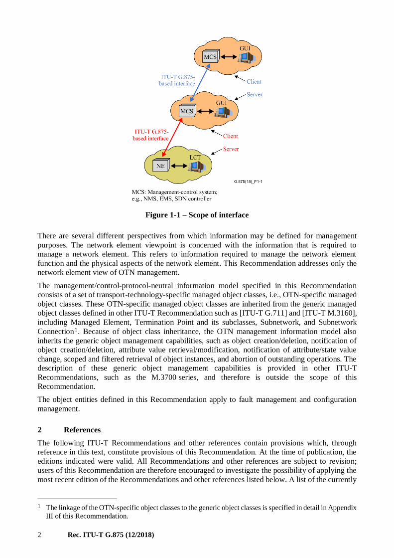
mangement/control interface, as shown in Figure 1-1, specifically for managing/controlling the OTN
functional capabilities of the network element (NE).
2 Rec. ITU-T G.875 (12/2018)
Figure 1-1 – Scope of interface
There are several different perspectives from which information may be defined for management
purposes. The network element viewpoint is concerned with the information that is required to
manage a network element. This refers to information required to manage the network element
function and the physical aspects of the network element. This Recommendation addresses only the
network element view of OTN management.
The management/control-protocol-neutral information model specified in this Recommendation
consists of a set of transport-technology-specific managed object classes, i.e., OTN-specific managed
object classes. These OTN-specific managed object classes are inherited from the generic managed
object classes defined in other ITU-T Recommendation such as [ITU-T G.711] and [ITU-T M.3160],
including Managed Element, Termination Point and its subclasses, Subnetwork, and Subnetwork
Connection1. Because of object class inheritance, the OTN management information model also
inherits the generic object management capabilities, such as object creation/deletion, notification of
object creation/deletion, attribute value retrieval/modification, notification of attribute/state value
change, scoped and filtered retrieval of object instances, and abortion of outstanding operations. The
description of these generic object management capabilities is provided in other ITU-T
Recommendations, such as the M.3700 series, and therefore is outside the scope of this
Recommendation.
The object entities defined in this Recommendation apply to fault management and configuration
management.
2 References
The following ITU-T Recommendations and other references contain provisions which, through
reference in this text, constitute provisions of this Recommendation. At the time of publication, the
editions indicated were valid. All Recommendations and other references are subject to revision;
users of this Recommendation are therefore encouraged to investigate the possibility of applying the
most recent edition of the Recommendations and other references listed below. A list of the currently
____________________
1 The linkage of the OTN-specific object classes to the generic object classes is specified in detail in Appendix
III of this Recommendation.

Rec. ITU-T G.875 (12/2018) 3
valid ITU-T Recommendations is regularly published. The reference to a document within this
Recommendation does not give it, as a stand-alone document, the status of a Recommendation.
[ITU-T G.709] Recommendation ITU-T G.709/Y.1331 (2016), Interfaces for the optical
transport network, plus Amendment 1 (2016), Amendment 2 (2018).
[ITU-T G.798] Recommendation ITU-T G.798 (2017), Characteristics of optical transport
network hierarchy equipment functional blocks, plus Amendment 1 (2018).
[ITU-T G.872] Recommendation ITU-T G.872 (2017), Architecture of optical transport
networks.
[ITU-T G.874] Recommendation ITU-T G.874 (/2017), Management aspects of optical
transport network elements.
[ITU-T G.7044] Recommendation ITU-T G.7044/Y.1347 (2011), Hitless adjustment of
ODUflex (GFP), plus Amendment 1 (02/2012).
[ITU-T G.7701] Recommendation ITU-T G.7701 (11/2016), Common control aspects, plus
Amendment 1 (03/2018).
[ITU-T G.7710] Recommendation ITU-T G.7710/Y.1701 (2012), Common equipment
management function requirements, plus Amendment 1 (11/2016).
[ITU-T G.7711] Recommendation ITU-T G.7711/Y.1702 (2018), Generic protocol-neutral
information model for transport resources.
[ITU-T G.8052] Recommendation ITU-T G.8052/Y.1346 (2016), Protocol-neutral management
information model for the Ethernet Transport capable network element.
[ITU-T M.3010] Recommendation ITU-T M.3010 (2000), Principles for a telecommunications
management network, plus Amendment 1 (12/2003), and Amendment 2
(11/2005).
[ITU-T M.3100] Recommendation ITU-T M.3100 (2005), Generic network information model.
[ITU-T Q.822] Recommendation ITU-T Q.822 (1994), Stage 1, stage 2 and stage 3
description for the Q3 interface – Performance management.
[ITU-T X.739] Recommendation ITU-T X.739 (1993), Information technology – Open
Systems Interconnection – Systems Management: Metric objects and attributes.
3 Terms and Definitions
3.1 Definitions from [ITU-T M.3100]
The following terms are defined in [ITU-T M.3100] and used in this Recommendation:
ASAP Alarm Severity Assignment Profile
CTP Connection Termination Point
TP Termination Point
TTP Trail Termination Point
3.2 Definitions from [ITU-T G.870]
The following terms are defined in [ITU-T G.870] and used in this Recommendation:
OCh Optical Channel
ODUk Optical Channel Data Unit-k
ODUkP Optical Channel Data Unit-k, Path

4 Rec. ITU-T G.875 (12/2018)
ODUkT Optical Channel Data Unit-k, Tandem connection sublayer
OPS Optical Physical Section
OTM Optical Transport Module
OTN Optical Transport Network
OTU Optical Channel Transport Unit
OTUk Optical Transport Unit-k
3.3 Definitions from [ITU-T G.872]
The following terms are defined in [ITU-T G.872] and used in this Recommendation:
OMS Optical Multiplex Section
OTS Optical Transmission Section
3.4 Definitions from [ITU-T G.798]
The following terms are defined in [ITU-T G.798] and used in this Recommendation:
A Adaptation function
GCC General Communication Channel
MP Management Point
TT Trail Termination function
3.5 Definitions from [ITU-T G.7710]
The following term is defined in [ITU-T G.7710] and used in this Recommendation:
ARC Alarm Reporting Control
4 Abbreviations and Acronyms
This Recommendation uses the following abbreviations and acronyms:
ARC Alarm Reporting Control
ASAP Alarm Severity Assignment Profile
BIAE Backward Incoming Alignment Error
CMISE Common Management Information Service Element
CORBA Common Object Request Broker Architecture
CTP Connection Termination Point
EMS Element Management System
GCC General Communication Channel
IAE Incoming Alignment Error
IDL Interface Definition Language
LP Layer Protocol
LTP Logical Termination Point
MP Management Point
NE Network Element
Rec. ITU-T G.875 (12/2018) 5
NIM Non-Intrusive Monitoring
NMS Network Management System
OCh Optical Channel
ODUk Optical Channel Data Unit-k
ODUkP Optical Channel Data Unit-k, Path
ODUkT Optical Channel Data Unit-k, Tandem connection sublayer
OMS Optical Multiplex Section
OMS-O Optical Multiplex Section – Overhead
OPS Optical Physical Section
OTM Optical Transport Module
OTN Optical Transport Network
OTS Optical Transmission Section
OTSi Optical Tributary Signal
OTSiA Optical Tributary Signal Assembly
OTSiG Optical Tributary Signal Group
OTSiG-O Optical Tributary Signal Group – Overhead
OTU Optical Channel Transport Unit
OUI Organizationally Unique Identifier
SDN Software-Defined Networking
SNMP Simple Network Management Protocol
TCM Tandem Connection Monitoring
TMN Telecommunication Management Network
TP Termination Point
TT Trail Termination function
TTP Trail Termination Point
UML Unified Modelling Language
5 Conventions
5.1 Information modeling conventions
5.1.1 UML modeling conventions
See [ITU-T G.7711] clause 5.1.
5.1.2 Model Artefact Lifecycle Stereotypes conventions
See [ITU-T G.7711] clause 5.2.
5.1.3 Forwarding entity terminology conventions
See [ITU-T G.7711] clause 5.3.

6 Rec. ITU-T G.875 (12/2018)
5.1.4 Conditional package conventions
See [ITU-T G.7711] clause 5.4.
5.1.5 Pictorial diagram conventions
See [ITU-T G.7711] clause 5.5.
6 Overview of the model
This Recommendation models the optical transport network (OTN) transport functions that are
relevant to OTN network elements management. These functions are defined in the equipment
specification [ITU-T G.798] for the termination, adaptation and connection functions of the OTN
layers, including Optical Transmission Section - Overhead (OTS-O), Optical Multiplex Section –
Overhead (OMS-O), Optical Tributary Signal Group – Overhead (OTSiG-O), Optical Channel –
Overhead (OCh-O), Optical Transmission Unit (OTU), Optical Data Unit (ODU), Tandem
connection sublayer of Optical Data Unit of level k (ODUkT), and the FlexO and OTSi adaptation
functions. In particular, the input and output information exchanged at the management point (MP)
are modelled. The termination, adaptation, and connections functions and input/output information
cover the areas of configuration, fault management, and performance management as described in
[ITU-T G.7710] and [ITU-T G.874]. Details of the management functions that need to be modelled
are provided in [ITU-T G.7710] and [ITU-T G.874].
In this Recommendation, managed resources and management support resources are modelled as
objects in the information model. The management view of a resource is a managed object. This
Recommendation specifies the properties of the resources visible for management. Objects with
similar properties are grouped into object classes. An object instance is an instantiation of an object
class. The properties of an object include the behaviour, attributes and operations that can be applied
to the object. An object instance is characterized by its object class and may possess multiple attribute
types and associated values. In the protocol-neutral model, object classes are represented as unified
modelling language (UML) classes.
Object classes, attribute types and operations are defined for the purpose of communicating network
management messages between systems. They need not be related to the structure of data stored
within those systems.
An object class may be a subclass of another class. A subclass inherits properties of its superclass, in
addition to possessing its own specific attributes and properties. In this Recommendation, the
OTN-specific transport object classes are defined. These object classes are not inherited from any
generic transport superclasses. In the future, when defining protocol-specific OTN object classes,
they could be mapped from the protocol-neutral OTN object classes and also inherited from the
protocol-specific generic transport object classes for additional properties.
In addition to the OTN resource, the model also includes object classes for management support
functions such as alarm reporting control and alarm severity assignment.
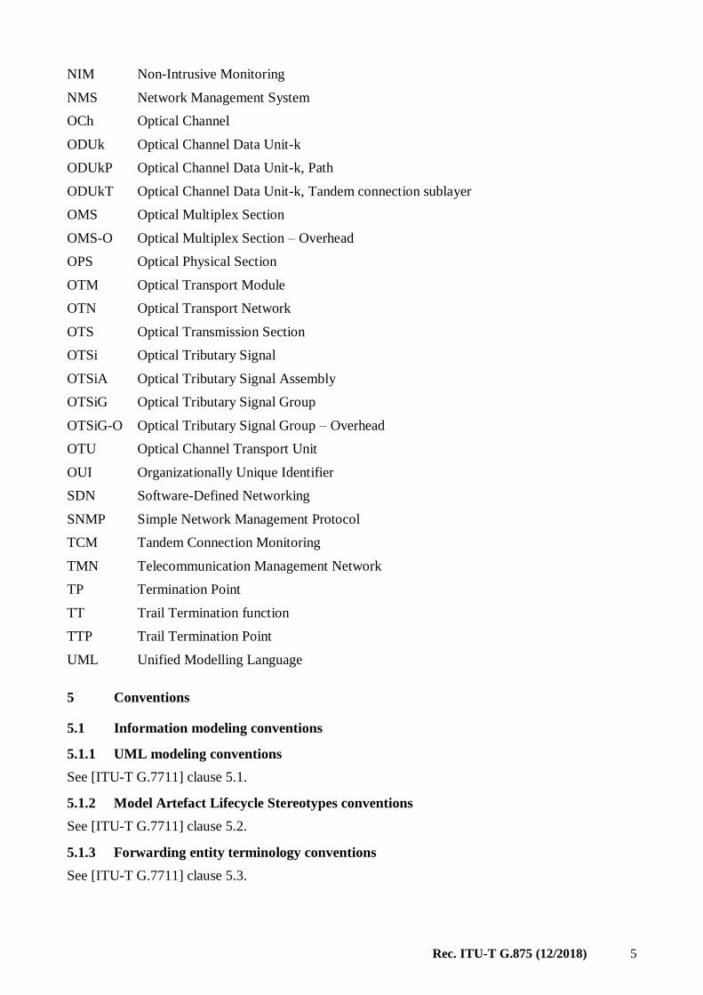
Figures 6-1 to 6-5 show the mapping between the OTN managed object classes and the OTN atomic
functions defined in Figures 1-1 to 1-5 of [ITU-T G.798].

Rec. ITU-T G.875 (12/2018) 7
Figure 6-1 – Overview of object class mapping to OTN atomic functions that support single-
OTU (SOTU) and muti-OTU (MOTU) interface
(Based on Figure 1-1 of [ITU-T G.798 (2017)])
Figure 6-2 – Overview of object class mapping to OTN atomic functions that support muti-
OTU (MOTUm) with management interface
(Based on Figure 1-2 of [ITU-T G.798 Corrigendum 1 (2018)])
8 Rec. ITU-T G.875 (12/2018)
Figure 6-3 – Overview of object class mapping to OTN atomic functions specific
for the non-associated overhead information
(Based on Figure 1-3 of [ITU-T G.798 Corrigendum 1 (2018)])

Rec. ITU-T G.875 (12/2018) 9
Figure 6-4 – Overview of object class mapping to OTN atomic functions for FlexO
(Based on Figure 1-4 of [ITU-T G.798 (2017)])

10 Rec. ITU-T G.875 (12/2018)

Rec. ITU-T G.875 (12/2018) 11
Figure 6-5 – Overview of object class mapping to OTN common atomic functions
(Based on Figure 1-5 of [ITU T G.798 Amendment 1 (2018)])
7 UML model class diagrams
The clause contains the UML model class diagrams of the OTN NE management-protocol-neutral
information model.
7.1 High-level overview
The UML diagrams below provide high-level overview of most of the ONT specific managed object
classes without showing the details, such as the attributes and operations of the object classes. More
details class diagrams for the individual fragments of the model are shown in the subsequent
subclauses, in which the attributes and operations are also shown.

12 Rec. ITU-T G.875 (12/2018)
Figure 7-1A – OTN model high-level overview

Rec. ITU-T G.875 (12/2018) 13
NOTE – This figure is also available from the ITU website here.
Figure 7-1B – OTN main entities

14 Rec. ITU-T G.875 (12/2018)
NOTE – This figure is also available from the ITU website here.
Figure 7-1C – OTN Inheritance
7.2 OxS-O fragment
NOTE – This figure is also available from the ITU website here.
Figure 7-2 – OTS-O and OMS-O entities

Rec. ITU-T G.875 (12/2018) 15
7.3 OCh fragment
NOTE – This figure is also available from the ITU website here.
Figure 7-3 – OCh entities

16 Rec. ITU-T G.875 (12/2018)
7.4 OTU fragment
NOTE – This figure is also available from the ITU website here.
Figure 7-4 – OTU entities
Rec. ITU-T G.875 (12/2018) 17
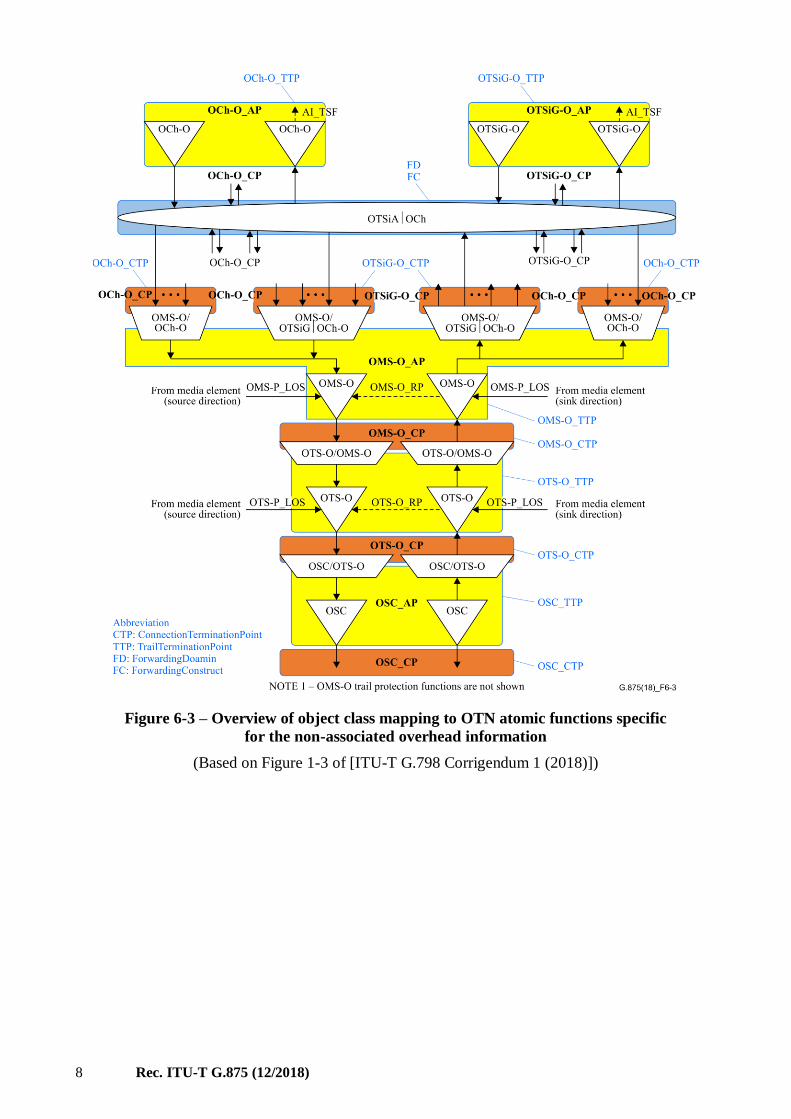
7.5 ODU fragment
NOTE – This figure is also available from the ITU website here.
Figure 7-5A – ODU entities
18 Rec. ITU-T G.875 (12/2018)
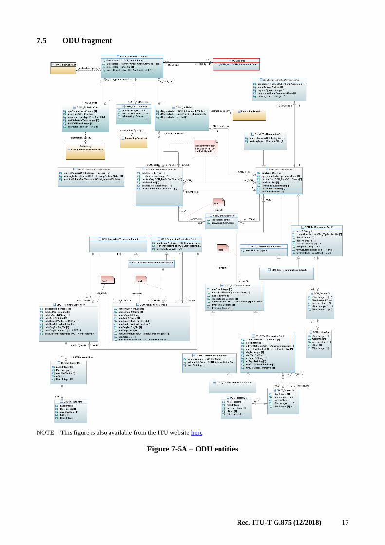
NOTE – This figure is also available from the ITU website here
Figure 7-5B – ODUCn and ODUk Pacs
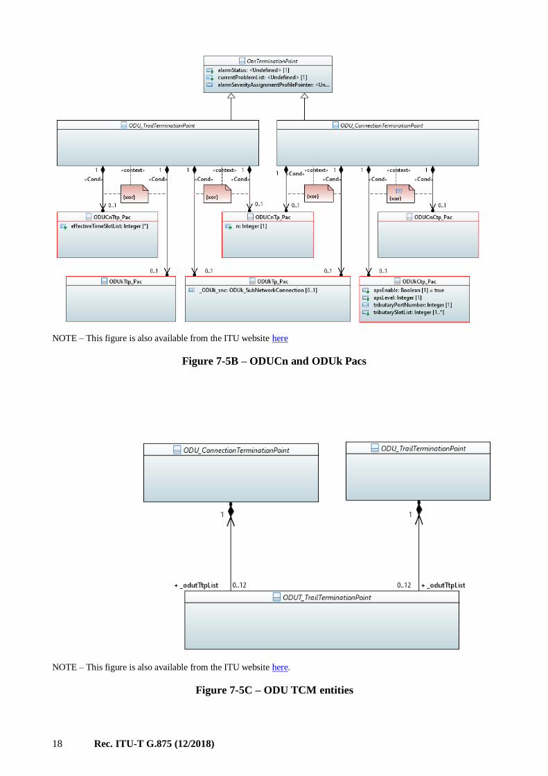
NOTE – This figure is also available from the ITU website here.
Figure 7-5C – ODU TCM entities

Rec. ITU-T G.875 (12/2018) 19
7.6 FlexO fragment
NOTE – This figure is also available from the ITU website here.
Figure 7-6 – FlexO entities
20 Rec. ITU-T G.875 (12/2018)
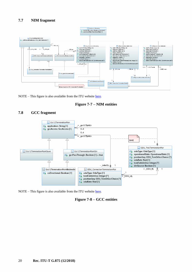
7.7 NIM fragment
NOTE – This figure is also available from the ITU website here.
Figure 7-7 – NIM entities
7.8 GCC fragment
NOTE – This figure is also available from the ITU website here.
Figure 7-8 – GCC entities

Rec. ITU-T G.875 (12/2018) 21
7.9 Protection fragment
NOTE – This figure is also available from the ITU website here.
Figure 7-9A – OCh protection

22 Rec. ITU-T G.875 (12/2018)
NOTE – This figure is also available from the ITU website here.
Figure 7-9B – ODU protection

Rec. ITU-T G.875 (12/2018) 23
NOTE – This figure is also available from the ITU website here.
Figure 7-9C – OTS-O and OMS-O trail protection

24 Rec. ITU-T G.875 (12/2018)
7.10 Performance monitoring (PM) fragment
NOTE – This figure is also available from the ITU website here.
Figure 7-10A – Performance monitoring entities

Rec. ITU-T G.875 (12/2018) 25
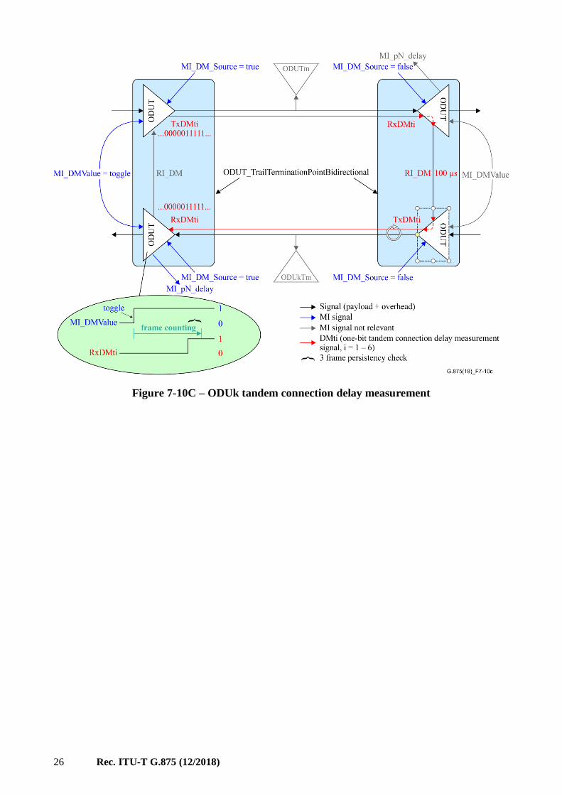
7.10.1 Delay measurement
The following figures provide an overview of the OTN delay measurement function showing
involved atomic functions, management information and managed object classes.
Figure 7-10B – ODU path delay measurement
26 Rec. ITU-T G.875 (12/2018)
Figure 7-10C – ODUk tandem connection delay measurement

Rec. ITU-T G.875 (12/2018) 27
NOTE – This figure is also available from the ITU website here.
Figure 7-10D – Delay Measurement entities
7.11 Fault management fragment
Figure 7-11 – Fault Management entities

28 Rec. ITU-T G.875 (12/2018)
8 UML model file
The ITU-T G.875 (ex. G.874.1) UML model is contained in a repository website. The following links
provide the pointers to the ITU-T G.875 UML model files and the supporting materials.
– G.875_v4.00_PAP.zip
This zip contains the ITU-T G.875 model files (i.e., the .project, .di, .notation and .uml files)
and the profiles.
The G.875 4.0 model uses the following modelling tool and profiles
• Eclipse 4.7.2 (i.e., version Oxygen)
• Papyrus 3.2.0,
• OpenModel_Profile 0.2.13,
• OpenInterfaceModel_Profile 0.8,
• ProfileLifecycle_Profile 0.0.4, and
• Gendoc v0.7.0 milestone 2
– G.875_v4.00_DD.zip
This zip file is the data dictionary.
– G.7711_v2.02_PAP.zip
This constains the ITU-T G.7711 model files. In order to use the ITU-T G.875 model, one
also needs to install the ITU-T G.7711 base model.
NOTE – The ITU-T G.875 UML information models and the Open Model Profile are specified using the
Papyrus open-source modelling tool. In order to view and further extend or modify the information model, one
will need to install the open source Eclipse software and the Papyrus tool, which are available at [b-Eclipse-
Papyrus]. The installation guide for Eclipse and Papyrus can be found in [b-ONF TR-515].

Rec. ITU-T G.875 (12/2018) 29
Annex A
OTN specification model
(This annex forms an integral part of this Recommendation.)
This annex describes how the Recommendation ITU-T G.7711 Specification model is used to
augment the Core model with the OTN specific properties.
A.1 LTP/LP Spec model
A.1.1 Overview of the core LTP/LP Spec model
Clause G.3.2 of [ITU-T G.7711] defines a generic logical termination point (LTP) and layer protocol
(LP) Spec model that provides a representation of LP specific parameters for the LTP. Reproduced
below is Figure G.3-18 of [ITU-T G.7711], which shows the LTP/LP spec elements.
Applies to inverse
multiplexing cases
CoreModel Diagram
Spec-LtpCapabilitySpecWithLtp
Applies to virtual
cases
Figure A.1-1 – Relating LTP/LP spec elements
(From Figure G.3-18 of [ITU-T G.7711] – Relating LTP/LP spec elements)
As shown in the figure, the LpSpec class is the touch point to anchor the spec elements for specifying
the various capabilities of a specific type of LP. Among the Spec elements, the following two are
particularly relevant to the layer specific parameters of the termination points defined in the
technology specific recommendations.
ConnectionPointAndAdapterSpec is defined in G.3.2.3.3 of [ITU-T G.7711] as follows:
The specification of the server facing connection point and the adapter that deals with the
transformation of a single signal of the layer protocol to/from the server. Equivalent to an
ITU-T CTP [ITU-T G.8052].

30 Rec. ITU-T G.875 (12/2018)
TerminationSpec is defined in clause G.3.2.3.11 of [ITU-T G.7711] as follows:
The specification of the layer protocol termination (including framing, modulation etc.). For
example, the specification of the function that takes a MAC frame and extracts the content
(removing the MAC address in the process).
Although it is not explicitly stated, the TerminationSpec is obviously equivalent to an ITU-T TTP.
A.1.2 Consideration of OTN specification cases for LTP/LP
Considering:
• The benefit of easy traceability between the attributes of the technology-specific OTN
TTP/CTP of the information models with the corresponding management information (i.e.,
the MI signals) of the ITU-T G.798 OTN technology specific equipment function
specifications,
– This Recommendation continues to keep the current TTP/CTP in the technology-specific
information models
• The equivalency of the TTP/CTP to the spec elements, namely TerminationSpec and
ConnectionPointAndAdapterSpec respectively,
– This Recommendation enhances the technology-specific information models to augment,
for each layer, the core model generic TerminationSpec and
ConnectionPointAndAdapterSpec with the technology-specific TTP and CTP.
A.1.3 OTN specification classes for LTP/LP
For each OTN layer, the core model generic TerminationSpec and ConnectionPointAndAdapterSpec
is augmented with the TTP and CTP object classes as shown in the following UML diagrams.
A.1.3.1 OTU specification classes for LTP/LP
Figure A.1-2 describes the OUT Spec case.

Rec. ITU-T G.875 (12/2018) 31
Figure A.1-2 – OTU Spec case
A.1.3.2 ODU specification classes for LTP/LP
Figure A.1-3 describes the ODU Spec case.

32 Rec. ITU-T G.875 (12/2018)
NOTE – This figure is also available from the ITU website here
Figure A.1-3 – ODU Spec case

Rec. ITU-T G.875 (12/2018) 33
Appendix I
Usage of the model for TCM and GCC
(This appendix does not form an integral part of this Recommendation.)
This appendix provides some examples to illustrate possible positions of TCM and GCC access
functions within ODUk TPs and how they will be represented in the information model. This
representation is defined via the use of containment relationships and the attributes PositionSeq,
Codirectional and Directionality.
The following ODUk layer network configuration will be used as a basis:

34 Rec. ITU-T G.875 (12/2018)
35 Rec. ITU-T G.875 (12/2018)
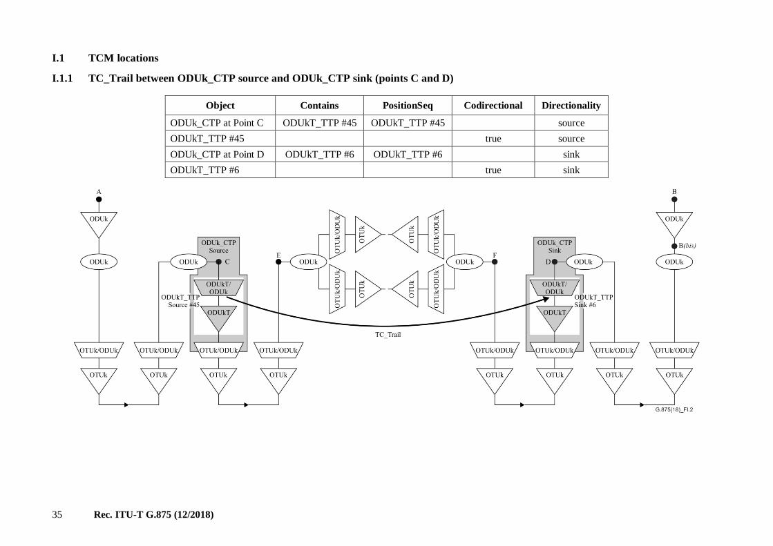
I.1 TCM locations
I.1.1 TC_Trail between ODUk_CTP source and ODUk_CTP sink (points C and D)
Object Contains PositionSeq Codirectional Directionality
ODUk_CTP at Point C ODUkT_TTP #45 ODUkT_TTP #45 source
ODUkT_TTP #45 true source
ODUk_CTP at Point D ODUkT_TTP #6 ODUkT_TTP #6 sink
ODUkT_TTP #6 true sink

36 Rec. ITU-T G.875 (12/2018)
I.1.2 TC_Trail between ODUk_CTP sink and ODUk_CTP source (points E and F)
Object Contains PositionSeq Codirectional Directionality
ODUk_CTP at Point E ODUkT_TTP #23 ODUkT_TTP #23 sink
ODUkT_TTP #23 false source
ODUk_CTP at Point F ODUkT_TTP #87 ODUkT_TTP #87 source
ODUkT_TTP #87 false sink

37 Rec. ITU-T G.875 (12/2018)
I.1.3 TC_Trail between ODUk_TTP source and ODUk_CTP source (points G and H)
Object Contains PositionSeq Codirectional Directionality
ODUk_TTP at Point G ODUkT_TTP #3 ODUkT_TTP #3 source
ODUkT_TTP #3 meaningless source
ODUk_CTP at Point H ODUkT_TTP #65 ODUkT_TTP #65 source
ODUkT_TTP #65 false sink

38 Rec. ITU-T G.875 (12/2018)
I.1.4 Two TC_Trail terminations within one ODUk_CTP

Rec. ITU-T G.875 (12/2018) 39
Object Contains PositionSeq Codirectional Directionality
ODUk_CTP at Point C ODUkT_TTP #19 ODUkT_TTP #19 source
ODUkT_TTP #19 true source
ODUk_CTP at Point E ODUkT_TTP #18 ODUkT_TTP #18 sink
ODUkT_TTP #18 false source
ODUk_CTP at Point F ODUkT_TTP #1
ODUkT_TTP #3
ODUkT_TTP #3
ODUkT_TTP #1
source
ODUkT_TTP #1 false sink
ODUkT_TTP #3 false sink

40 Rec. ITU-T G.875 (12/2018)
I.2 GCC access locations
I.2.1 COMMS channel between two ODUk_TTPs (points A and B, TT atomic functions are included)
Object Contains PositionSeq Codirectional Directionality
ODUk_TTP at Point A GCC12_TP #100 empty source
GCC12_TP #100 meaningless source
ODUk_TTP at Point B GCC12_TP #2 empty sink
GCC12_TP #2 meaningless sink

41 Rec. ITU-T G.875 (12/2018)
I.2.2 COMMS channel between ODUk_CTP and ODUk_TTP (Points C and B(bis) TT atomic function at B(bis) is not included)
Object Contains PositionSeq Codirectional Directionality
ODUk_CTP at Point C GCC12_TP #22 GCC12_TP #22 source
GCC12_TP #22 true source
ODUk_TTP at Point B GCC12_TP #13 GCC12_TP #13 sink
GCC12_TP #13 meaningless sink

42 Rec. ITU-T G.875 (12/2018)
I.2.3 Several COMMS channels

Rec. ITU-T G.875 (12/2018) 43
Object Contains Position
Seq
Codirec-
tional
Direc-
tionality GCCAccess
ODUk_CTP at Point E GCC12_TP #6
GCC12_TP #9
GCC12_TP #9
GCC12_TP #6
bidirectional
GCC12_TP #6 false bidirectional GCC1
GCC12_TP #9 true bidirectional GCC1
ODUk_CTP at Point F GCC12_TP #4
GCC12_TP #45
GCC12_TP #2
GCC12_TP #8
GCC12_TP #8
GCC12_TP #2
GCC12_TP #45
GCC12_TP #4
bidirectional
GCC12_TP #4 false bidirectional GCC1
GCC12_TP #45 false bidirectional GCC2
GCC12_TP #2 true bidirectional GCC1
GCC12_TP #8 true bidirectional GCC2
ODUk_CTP at Point
B(bis)
GCC12_TP #34
GCC12_TP #5
GCC12_TP #5
GCC12_TP #34
bidirectional
GCC12_TP #34 false bidirectional GCC2
GCC12_TP #5 true bidirectional GCC2
44 Rec. ITU-T G.875 (12/2018)
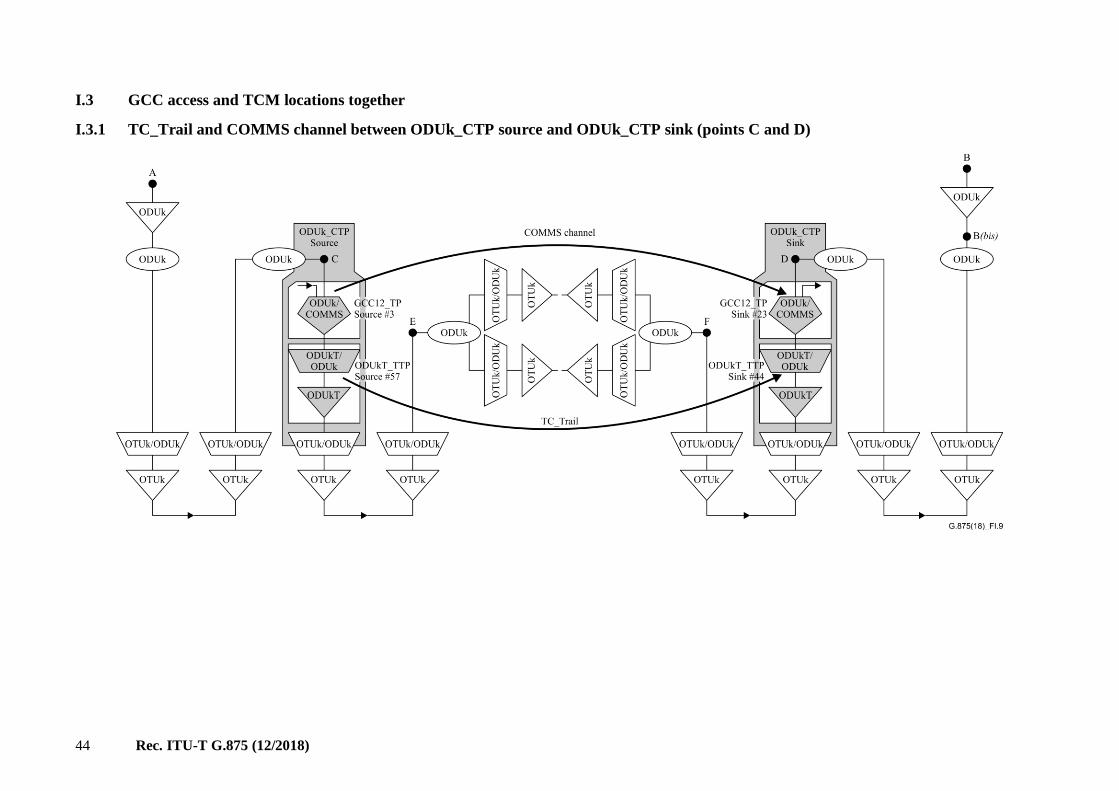
I.3 GCC access and TCM locations together
I.3.1 TC_Trail and COMMS channel between ODUk_CTP source and ODUk_CTP sink (points C and D)

Rec. ITU-T G.875 (12/2018) 45
Object Contains PositionSeq Codirectional Directionality
ODUk_CTP at Point C GCC12_TP #3
ODUkT_TTP #57
ODUkT_TTP #57
GCC12_TP #3
source
GCC12_TP #3 true source
ODUkT_TTP #57 true source
ODUk_CTP at Point D GCC12_TP #23
ODUkT_TTP #44
ODUkT_TTP #44
GCC12_TP #23
sink
GCC12_TP #23 true sink
ODUkT_TTP #44 true sink

46 Rec. ITU-T G.875 (12/2018)
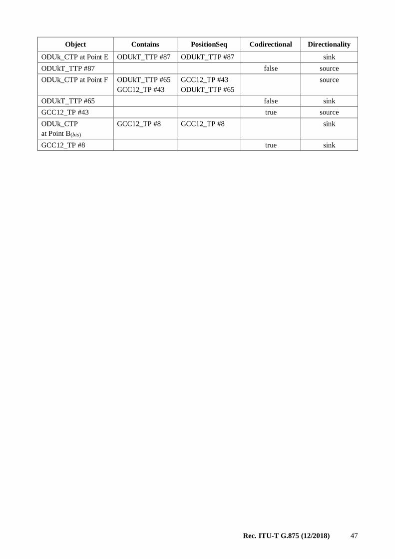
I.3.2 Terminating TC_Trail and inserting GCC within one ODUk_CTP
Rec. ITU-T G.875 (12/2018) 47
Object Contains PositionSeq Codirectional Directionality
ODUk_CTP at Point E ODUkT_TTP #87 ODUkT_TTP #87 sink
ODUkT_TTP #87 false source
ODUk_CTP at Point F ODUkT_TTP #65
GCC12_TP #43
GCC12_TP #43
ODUkT_TTP #65
source
ODUkT_TTP #65 false sink
GCC12_TP #43 true source
ODUk_CTP
at Point B(bis)
GCC12_TP #8 GCC12_TP #8 sink
GCC12_TP #8 true sink
48 Rec. ITU-T G.875 (12/2018)
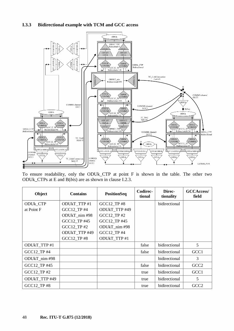
I.3.3 Bidirectional example with TCM and GCC access
To ensure readability, only the ODUk_CTP at point F is shown in the table. The other two
ODUk_CTPs at E and B(bis) are as shown in clause I.2.3.
Object Contains PositionSeq Codirec-
tional
Direc-
tionality
GCCAccess/
field
ODUk_CTP
at Point F
ODUkT_TTP #1
GCC12_TP #4
ODUkT_nim #98
GCC12_TP #45
GCC12_TP #2
ODUkT_TTP #49
GCC12_TP #8
GCC12_TP #8
ODUkT_TTP #49
GCC12_TP #2
GCC12_TP #45
ODUkT_nim #98
GCC12_TP #4
ODUkT_TTP #1
bidirectional
ODUkT_TTP #1 false bidirectional 5
GCC12_TP #4 false bidirectional GCC1
ODUkT_nim #98 bidirectional 3
GCC12_TP #45 false bidirectional GCC2
GCC12_TP #2 true bidirectional GCC1
ODUkT_TTP #49 true bidirectional 5
GCC12_TP #8 true bidirectional GCC2

Rec. ITU-T G.875 (12/2018) 49
I.3.4 GCC12TP orientation
Figure I.12 – Bidirectional Gcc12Tp contained by bidirectional TTP
Figure I.13 – Bidirectional Gcc12Tp contained by bidirectional TTP and CTP

50 Rec. ITU-T G.875 (12/2018)
Figure I.14 – Bidirectional Gcc12Tp contained by bidirectional TTP and CTP

Rec. ITU-T G.875 (12/2018) 51
Appendix II
Management termination points
(This appendix does not form an integral part of this Recommendation.)
II.1 State management
The ONE shall indicate to the OS when a termination point is no longer able to supervise the signal
(e.g., implementing equipment has a fault or loss of power).
II.2 Location of TPs inside a ONE
Figure II.1 show possible locations of TPs inside a network element (the network elements are
just examples; it is not necessary to define specific NE types):
Figure II.1 – Example of TPs in an optical amplifier
II.3 Definitions of ONE termination points
An otsTTPSource originates a WDM transmission trail between two adjacent optical network
elements. This object class represents the point where the optical line signal outgoes from the NE.
There is always one instance of an otsTTPSource per line output port.
An otsTTPSink terminates a WDM transmission trail between two adjacent optical network. This
object class represents the point where the optical line signal incomes into the NE. There is always
one instance of an otsTTPSink per line input port.
An omsCTPSource originates an optical multiplex section link connection between two adjacent
optical network elements. There is one instance (for the time being; in future there may be more) of
an omsCTPSource per line output port.
An omsCTPSink terminates an optical multiplex section link connection between two adjacent
optical network elements. There is one instance (for the time being; in future there may be more) of
an omsCTPSink per line input port.

52 Rec. ITU-T G.875 (12/2018)
An omsTTPSource originates an optical multiplex section trail between two (not necessarily
adjacent) optical network elements. There is one instance (for the time being; in future there may be
more) of an omsTTPSource per line output port.
An omsTTPSink terminates an optical multiplex section trail between two (not necessarily adjacent)
optical network elements. There is one instance (for the time being; in future there may be more) of
an omsTTPSink per line input port.
An ochCTPSource originates an optical channel link connection between two (not necessarily
adjacent) optical network elements. There is one instance of an ochCTPSource per wavelength
channel in a line output port.
An ochCTPSink terminates an optical channel link connection between two (not necessarily
adjacent) optical network elements. There is one instance of an ochCTPSource per wavelength
channel in a line input port.
An ochTTPSource originates an optical channel trail between two (not necessarily adjacent) optical
network elements. There is one instance of an ochTTPSource per OCh adapter.
An ochTTPSink terminates an optical channel trail between two (not necessarily adjacent) optical
network elements. There is one instance of an ochTTPSink per OCh adapter.

Rec. ITU-T G.875 (12/2018) 53
Appendix III
Mapping of ITU-T G.798 atomic functions to ITU-T G.874.1 model artefacts
(This appendix does not form an integral part of this Recommendation.)
This appendix provides further detail mapping between the [ITU-T G.798] atomic functions and the
ITU-T G.874.1 UML model artifacts. Note that in some cases a 1:1 mapping is not possible.
Table III.1 – Mapping between [ITU-T G.798] OTN atomic functions and UML model artifacts
For further study

54 Rec. ITU-T G.875 (12/2018)
Appendix IV
UML model data dictionary
(This appendix does not form an integral part of this Recommendation.)
The Data Dictionary contains, in MS Word document format, the details of the OTN NE
management-protocol-neutral information model, including the description and properties of the
object classes and their attributes and operations. This detailed information is generated automatically
by a Gendoc tool from the UML model.
The ITU-T G.874.1 data dictionary is provided in the G.875_v4.0_DD.zip file at the repository
mentioned in clause 8.
Rec. ITU-T G.875 (12/2018) 55
Appendix V
Overview of object class mapping to OxS-O trail protection sub-layer functions
(This appendix does not form an integral part of this Recommendation.)
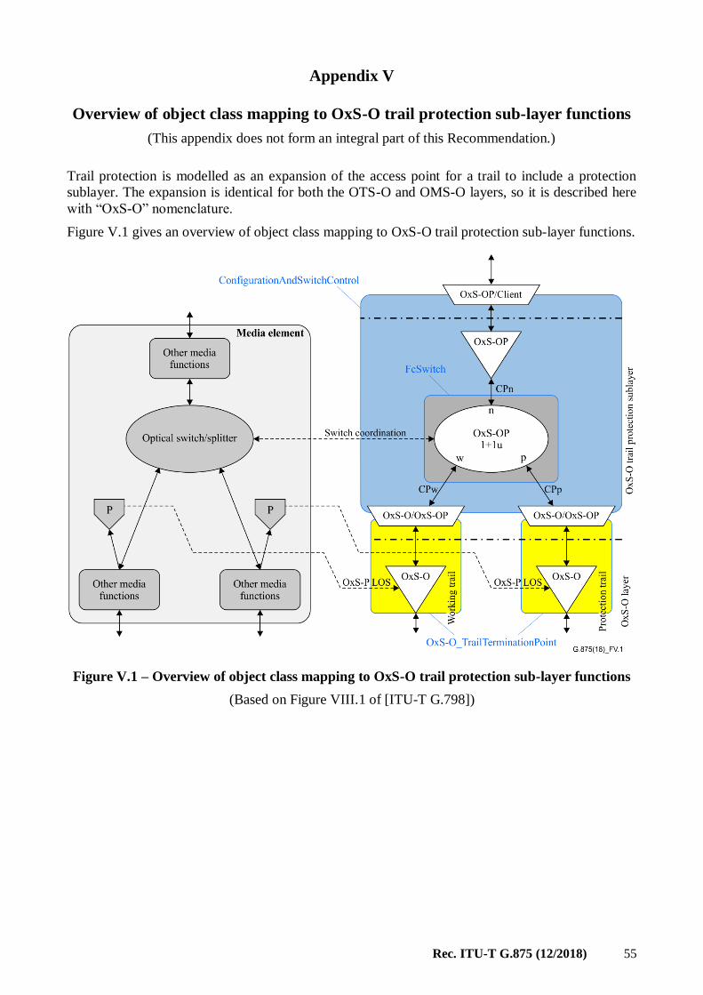
Trail protection is modelled as an expansion of the access point for a trail to include a protection
sublayer. The expansion is identical for both the OTS-O and OMS-O layers, so it is described here
with “OxS-O” nomenclature.
Figure V.1 gives an overview of object class mapping to OxS-O trail protection sub-layer functions.
Figure V.1 – Overview of object class mapping to OxS-O trail protection sub-layer functions
(Based on Figure VIII.1 of [ITU-T G.798])

56 Rec. ITU-T G.875 (12/2018)
Bibliography
[b-Eclipse-Papyrus] Papyrus Eclipse UML Modelling Tool <https://www.eclipse.org/papyrus/>
[b-ONF TR-515] ONF TR-515_Papyrus-Guidelines <https://3vf60mmveq1g8vzn48q2o71a-
wpengine.netdna-ssl.com/wp-content/uploads/2018/08/TR-
515_Papyrus_Guidelines_v1.3-1-1.pdf> <https://community.opensourcesdn.org/wg/EAGLE/document/171>


Printed in Switzerland Geneva, 2019
SERIES OF ITU-T RECOMMENDATIONS
Series A Organization of the work of ITU-T
Series D Tariff and accounting principles and international telecommunication/ICT economic and policy issues
Series E Overall network operation, telephone service, service operation and human factors
Series F Non-telephone telecommunication services
Series G Transmission systems and media, digital systems and networks
Series H Audiovisual and multimedia systems
Series I Integrated services digital network
Series J Cable networks and transmission of television, sound programme and other multimedia signals
Series K Protection against interference
Series L Environment and ICTs, climate change, e-waste, energy efficiency; construction, installation
and protection of cables and other elements of outside plant
Series M Telecommunication management, including TMN and network maintenance
Series N Maintenance: international sound programme and television transmission circuits
Series O Specifications of measuring equipment
Series P Telephone transmission quality, telephone installations, local line networks
Series Q Switching and signalling, and associated measurements and tests
Series R Telegraph transmission
Series S Telegraph services terminal equipment
Series T Terminals for telematic services
Series U Telegraph switching
Series V Data communication over the telephone network
Series X Data networks, open system communications and security
Series Y Global information infrastructure, Internet protocol aspects, next-generation networks, Internet of Things and smart cities
Series Z Languages and general software aspects for telecommunication systems