iv€¦ · an electric circuit. the current through the resistor is measured by connecting an...
TRANSCRIPT
AIMTo study the dependence of the potential difference across a resistor on thecurrent through it and to determine its resistance and to verify the Ohm’s law.
THEORYAccording to the Ohm’s law, the potential difference (V) across the ends ofa resistor is directly proportional to the current (I) through it provided itstemperature remains the same. That is
V ∝ I
or =I
Vconstant = R
or V = RI.
Here R is a constant for the given resistor at a given temperature and is calledits resistance. The SI unit of resistance is ohm (Ω). A graph between the potentialdifference across the two ends of a resistor and the current through it is astraight line pasing through the origin. The slope of this graph gives theresistance R of the resistor. To verify the Ohm’s law, we measure the potentialdifference across the two ends of a resistor at different currents through it inan electric circuit. The current through the resistor is measured by connectingan ammeter in series with it. The potential difference across the two ends ofthe resistor is measured by connecting the voltmeter in parallel with it. Astraight line graph obtained between V and I verifies the ohm’s law.
E x p e r i m e n t 48
UNIT IV
How ThingsWork
17-04-2018

Laboratory Manual Science
200
MATERIALS REQUIREDA resistor of about 5 Ω, an ammeter ( 0 - 3 A), a voltmeter (0 - 10 V), fourdry cells of 1.5 V each with a cell holder (or a battery eliminator), a plugkey, connecting wires, and a piece of sand paper.
PROCEDURE1. Note the range and least count of the given ammeter and the voltmeter.
2. Fresh connecting wires have an insulating layer on it. Similarly theconnecting wires lying unused for some time may also develop aninsulating layer. (How?) It is therefore important to clean the ends ofconnecting wires using a sand paper.
3. Draw a circuit diagram for studying the Ohm’s law as shown in Fig.48.1 in your notebook. Observe how different components like theammeter, voltmeter, resistor, and the plug key are connected withthe cells (or battery eliminator).
4. Set up the circuit by connecting different components with the helpof connecting wires.Initially connect only onecell in the circuit (that ismake cell connectionsbetween points A and B).In case a batteryeleminator is used, keepthe rating of theeliminator at theminimum (say at 2 V).
5. Make sure that thepositive and negativeterminals of the ammeterand voltmeter arecorrectly connected in the circuit as shown in Fig. 48.1. Get thecircuit set up by you checked by the teacher, before inserting thekey into the plug.
6. Insert the key in the plug to let the current establish in the circuit.Note the readings of the ammeter and voltmeter and record them.The voltmeter measures the potential difference (V) across the twoends X and Y of the resistor, and the ammeter measures the currentI through it. Remove the key from the plug to avoid unnecessaryheating of wires. (How does it happen? Think it in accordance withthe Joule’s law of heating.)
7. Now instead of using one cell in the circuit, connect two cells in thecircuit (that is make cell connections between points A and C, in case
Fig. 48.1 : An electric circuit for studying
Ohm’s law
17-04-2018

How Things Work
201
Sl. Number of cells Current through Potential difference Resistance of the
No. used in the the resistor, I across the ends of resistor,circuit the resistor, V R = V/I
(A) (V) ()
1. 1
2. 2
3. 3
4. 4
a battery eliminator is used, increase its rating. Insert the key in thecircuit. Note and record the voltmeter and ammeter readings.
8. Repeat the experiment by connecting three and four cells in the circuit.
OBSERVATIONS AND CALCULATIONS(i) Range of the ammeter = ___ - ___ A.(ii) Least count of the ammeter = ___ A.(iii) Range of the voltmeter = ___ ___ V.(iv) Least count of the voltmeter = ___ V.
Mean value of resistance R of the resistor = _____ .
GRAPHFind the range of variation in the values of I and V. Choose appropriatescales for the I and V along the x- and y-axesrespectively on the graph paper. Mark the pointson the graph paper for each value of current Iand corresponding value of potential differenceV (Fig. 48.2). Join all the points as a smoothline as possible such that most of the points lieon it. Find the slope of this straight line graphby choosing two points P and Q on it. This slopeis the resistance of the resistor used in thecircuit (Fig. 48.1).
QMslope
MP
=12
12
II
VV
.
Extend the straight line of the graph backwardsto check whether it meets the origin of thegraph paper.
Fig. 48.2 : Verification Ohm’s law
17-04-2018
Laboratory Manual Science
202
RESULTS AND DISCUSSION• Compare the value of resistance R of the resistor obtained from the
calculations (as given in the observation table) and obtained from thegraph.
• The value of resistance R of resistor for all values of current through itremains the same (or almost same). The graph between V and I is astraight line and passes through the origin. This verifies the Ohm’slaw.
PRECAUTIONS AND SOURCES OF ERROR• The connecting wires should be thick copper wires and the insulation
of their ends should be removed using the sand paper.
• Connections should be tight otherwise some external resistance mayintroduce in the circuit.
• The ammeter should be connected in series with the resistor such thatthe current enters at the positve terminal and leaves at the negativeterminal of the ammeter.
• Voltmeter should always be connected in parallel to resistor.
• The pointers of the ammeter and voltmeter should be at zero markwhen no current through the circuit. If not, then ask your teacher tocorrect it.
• Current should be passed through the circuit for a short time whiletaking observations; otherwise current would cause unnecessaryheating in the circuit. Heating may change the resistance of resistors.
NOTE FOR THE TEACHER
• If a resistor of known resistance is not available, a piece ofnichrome wire of suitable length may also be used.
• In place of dry cells, Leclanche, Daniel cells can be used. A batteryeliminator may also be used. In case a battery eliminator is used,it is suggested to guide students accordingly while connecting itin the circuit and taking observations.
• In case if an accumulator or battery is used in place of cells oreliminator to draw the current in the circuit then a rheostat orvariable resistance box can be used to change the current flowingthrough the circuit.
• In case your school laboratory possesses the voltmeter andammeter of ranges other than the prescribed ranges, then theresistors may be so chosen that an appreciable deflection mayappear in the ammeter and voltmeter.
17-04-2018
How Things Work
203
QUESTIONS• In this experiment it is advised to take out the key from the plug
when the observations are not being taken. Why?
• Suppose the ammeter (or voltmeter) you are using in thisexperiment do not have positive (+) and negative (-) terminalmarkings. How will you use such ammeter (or voltmeter) in thecircuit?
• If the resistor of a known resistance value is replaced with anichrome wire of 10 cm length (say). How do the values of currentthrough the nichrome wire and potential difference across thetwo ends of it may change? How the values will change if thereplaced wire is of manganin in place of nichrome?
• Suppose in this experiment you see that the deflection on ammeter(or voltmeter) scale goes beyond the full scale. What will you inferfrom such an observation? What will you infer if the deflectiontakes place in opposite direction?
• Why is it advised to clean the ends of connecting wires beforeconnecting them?
17-04-2018
Laboratory Manual Science
204
AIMTo study the factors that affect the resistance of a resistor.
THEORYOn applying the Ohm’s law, it is observed that the resistance of a resistordepends on its length, on its area of cross-section and on the nature of itsmaterial. Precise measurements have shown that the resistance (R) of auniform metallic conductor is directly proportional to its length (l) andinversely proportional to the area of cross-section (A). That is, R ∝ l and
1R
Aα . Thus
A
lρR = (1)
Here ρ is a constant of proportionality and is called the electrical resistivity of
the material of the conductor. The SI unit of resistivity is ohm meter (Ω m).
In this experiment, we study these factors in an electric circuit byemploying different resistors (wires) of different lengths and areas of cross-section. Using Ohm’s law, the resistance of a conductor in an electric circuitcan be determined by measuring the current through it and potentialdifference across its ends. An ammeter (connected in series with the resistor)measures the current through it and a voltmeter (connected parallely withthe resistor) measures the potential difference across its two ends.
E x p e r i m e n t 49
17-04-2018

How Things Work
205
MATERIALS REQUIREDTwo SWG-20 (standard wire gauge) constantan (or manganin) wires oflengths 10 cm and 20 cm respectively, one SWG-24 constantan(or manganin) wire of 10 cm length, one SWG-20 (or SWG-24) nichromewire of 10 cm length (all wires must be attached with the connectors atboth the ends such as crocodile clips), an ammeter (range 0 – 500 mA), avoltmeter (range 0 – 5 V), four dry cells of 1.5 V each with a cell holder (ora battery eliminator), a plug key, crocodile clips, connecting wires and apiece of sand paper.
The area of cross-section of a SWG-20 wire: 5.178 × 10⁻⁷ m2; and thearea of cross-section of a SWG-24 wire: 2.05 × 10⁻⁷m2.
PROCEDURE1. Note the range and least count of the given
ammeter and the voltmeter.
2. Fresh connecting wires have an insulatinglayer at the top. Similarly the connectingwires lying unused for some time may alsodevelop an insulating layer. (How?) It istherefore important to clean the ends ofconnecting wires using a sand paper.
3. Draw a circuit diagram for studying thefactors that affect the resistance of a resistor,as shown in Fig. 49.1 in your notebook.Observe how different components like theammeter, voltmeter, and the plug key areconnected with the cells or battery eliminator.Note that a resistor is to be connected in thecircuit between points A and B.
4. Set up the circuit by connecting differentcomponents with the help of connectingwires. Connect all the four cells in the circuit.In case if a battery eleminator is used, keepthe rating of the eliminator at about 6 V.
5. Label the given wires (resistors) as following:
SWG-20 constantan (or manganin) wire oflength 10 cm as wire 1, SWG 20 constantan(or manganin) wire of length 20 cm as wire2, SWG-24 constantan (or manganin) wire oflength 10 cm as wire 3, and SWG-20 (orSWG-24) nichrome wire of length 10 cmas wire 4.
Fig. 49.1 : (a) Electric circuit for studying
the factors that affects the
resistance of a resistor;
(b) Different wires to be used
as resistor
(a)
(b)
17-04-2018
Laboratory Manual Science
206
Sl. Label of the Resistor Current through Potential difference ResistanceNo. connected between the resistor, I across the ends of of the resistor,
points A and B resistor, V R = V/I
(mA) (A) (V) (Ω)
1. Wire 1
2. Wire 2
3. Wire 3
4. Wire 4
All the wires must be attached to connectors such as crocodile clips,as shown in Fig. 49.1(b). This will ensure that the entire length of thewire will come in the circuit as a resitor.
6. Connect wire 1 between points A and B. Make sure that the positiveand negative terminals of the ammeter and voltmeter are correctlyconnected in the circuit as shown in Fig. 49.1. Get the circuitchecked by the teacher, before inserting the key into the plug.
7. Insert the key in plug to let the current establish in the circuit. Notethe readings of the ammeter and voltmeter and record them. Ensurethat the key is removed from the plug just after taking the ammeterand voltmeter readings to avoid unnecessary heating of wires.
8. Now replace the wire 1 by the wire 2. Insert the key in the plug andmeasure the current through wire 2 and measure the potentialdifference across the ends of the wire 2. Notice the difference in thevalues of current and potential difference. Remove the key.
9. Repeat step 8 for wires 3 and 4.
OBSERVATIONS AND CALCULATIONS(i) Range of the ammeter = ___ - ___ A.(ii) Least count of the ammeter = ___ A.
(iii) Range of the voltmeter = ___ − ___ V.
(iv) Least count of the voltmeter = ___ V.
RESULTS AND DISCUSSIONInfer about the factors that affects the resistance of a resistor and answerthe following:
• How does it change with length?
• How does it change with the area of cross-section?
• How does it change with the resistivity of the material of the wire? (Getthe resistivity of the materials from the textbook/Appendix - I).
17-04-2018
How Things Work
207
PRECAUTIONS• The connecting wires should be thick copper wires and the insulation
of their ends should be removed using the sand paper.
• Connections should be tight otherwise some external resistance mayintroduce in the circuit.
• The ammeter should be connected in series with the resistor such thatthe current enters at the positve terminal and leaves at the negativeterminal of the ammeter.
• Voltmeter should always be connected in parallel to resistor.
• The pointers of the ammeter and voltmeter should be at zero markwhen no current is flowing through the circuit. If not, then ask yourteacher to correct it.
• Current should be passed through the circuit for a short time whiletaking observations; otherwise current would cause unnecessaryheating in the circuit. Heating may change the resistance of resistors.
NOTE FOR THE TEACHER
• The number of cells to be used in the circuit is not fixed. Thenumber of cells or the rating of the battery eliminator will, however,depend on the wires to be used as resistors in the circuit to givean appreciable amount of current to be measured by the ammeter.
• In place of dry cells a battery eliminator or a 9 V battery may beused. In case a battery eliminator is used, it is suggested to guidestudents accordingly while connecting it in the circuit and takingobservations.
• In case your school laboratory possesses the voltmeter andammeter of ranges other than the prescribed ranges, then theresistors may be chosen such that an appreciable deflection mayappear on the ammeter and voltmeter scales.
• In this experiment it is suggested to use SWG-20 and SWG-24constantan (or manganin) and nichrome wires. However this issuggestive and not mandatory. In case, these are not availableother wires may also be used. It is suggested that the choice ofwires should be judicious to get an appreciable deflection on thescales of the ammeter and voltmeter available in the laboratory.Further the area of cross-section of each wire should also beprovided to the students. Appendix - J may be consulted for thispurpose. In case if the standard wire gauge of the wires are notknown, the diameter of the wire may be determined using ascrew gauge.
17-04-2018
Laboratory Manual Science
208
QUESTIONS• A thick and a thin wire of same length and material are connected
to the same source. Which of the two will draw more currentfrom the source?
• A copper wire is stretched uniformly to double its length; howwill its resistance change? Will its resistivity also be changed?
• What happens to the value of current if positions of battery andammeter are interchanged in such a manner that the currententers at the positive terminal of the ammeter?
• On what factors does the resistance of a conductor depend?
• If the plug key is interchanged by the ammeter in this experiment,would you be able to perform the experiment?
17-04-2018
How Things Work
209
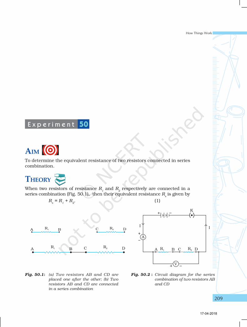
AIMTo determine the equivalent resistance of two resistors connected in seriescombination.
THEORYWhen two resistors of resistance R
1 and R
2 respectively are connected in a
series combination (Fig. 50.1), then their equivalent resistance Rs is given by
Rs = R
1 + R
2. (1)
E x p e r i m e n t 50
Fig. 50.1: (a) Two resistors AB and CD are
placed one after the other; (b) Two
resistors AB and CD are connected
in a series combination
Fig. 50.2 : Circuit diagram for the series
combination of two resistors AB
and CD
17-04-2018
Laboratory Manual Science
210
In order to determine the resistance of a combination of resistors inseries, the current I flowing through the circuit is measured with an ammeterconnected in series with the combination. The potential difference V acrossthe combination of resistors is measured with a voltmeter connected inparallel (Fig. 50.2).
MATERIALS REQUIREDTwo resistors of (each of 2 W resistance), an ammeter (range 0 – 5 A), avoltmeter (range 0 – 5 V), three dry cells of 1.5 V each with a cell holder (ora battery eliminator), a plug key, connecting wires and a piece of sandpaper.
PROCEDURE1. Note the range and least count of the given ammeter and the voltmeter.
2. Fresh connecting wires also have an insulating enamel layer at thetop. Similarly the connecting wires lying unused for some time mayalso develop an insulating layer. (How?) It is therefore important toclean the ends of connecting wires using a sand paper.
3. Draw a circuit diagram for the series combination of resistors as shownin Fig. 50.2 in your notebook. Observe how different components likethe ammeter, voltmeter, combination of resistors in series (of knownresistances R
1 and R
2) and the plug key are connected with the cell(s)
(or battery eliminator).
4. Place the given resistors one after the other and join the ends labelledB and C as shown in Fig. 50.1. Set up the circuit by connectingdifferent components with the help of connecting wires as shown inthe circuit diagram.
5. Make sure that the positive and negative terminals of the ammeterand voltmeter are correctly connected in the circuit as shown in Fig.50.2. Get the circuit set up by you checked by the teacher, beforeinserting the key into the plug.
6. Insert the key in the plug to let the current establish in the circuit.Note the readings of the ammeter and voltmeter and record them.The voltmeter measures the potential difference (V) across the twoends A and D of the series combination of two resistors, and theammeter measures the current I through the series combination.Remove the key from the plug to avoid unnecessary heating of wires(How does it happen? Think it in accordance with the Joule’s law ofheating.)
7. Repeat the activity for three different values of current through thecircuit and record the readings of the ammeter and voltmeter in eachcase. The current through the circuit may either be decreased or
17-04-2018
How Things Work
211
increased by changing the number of cells in the circuit (or by changingthe settings of the battery eliminator terminal).
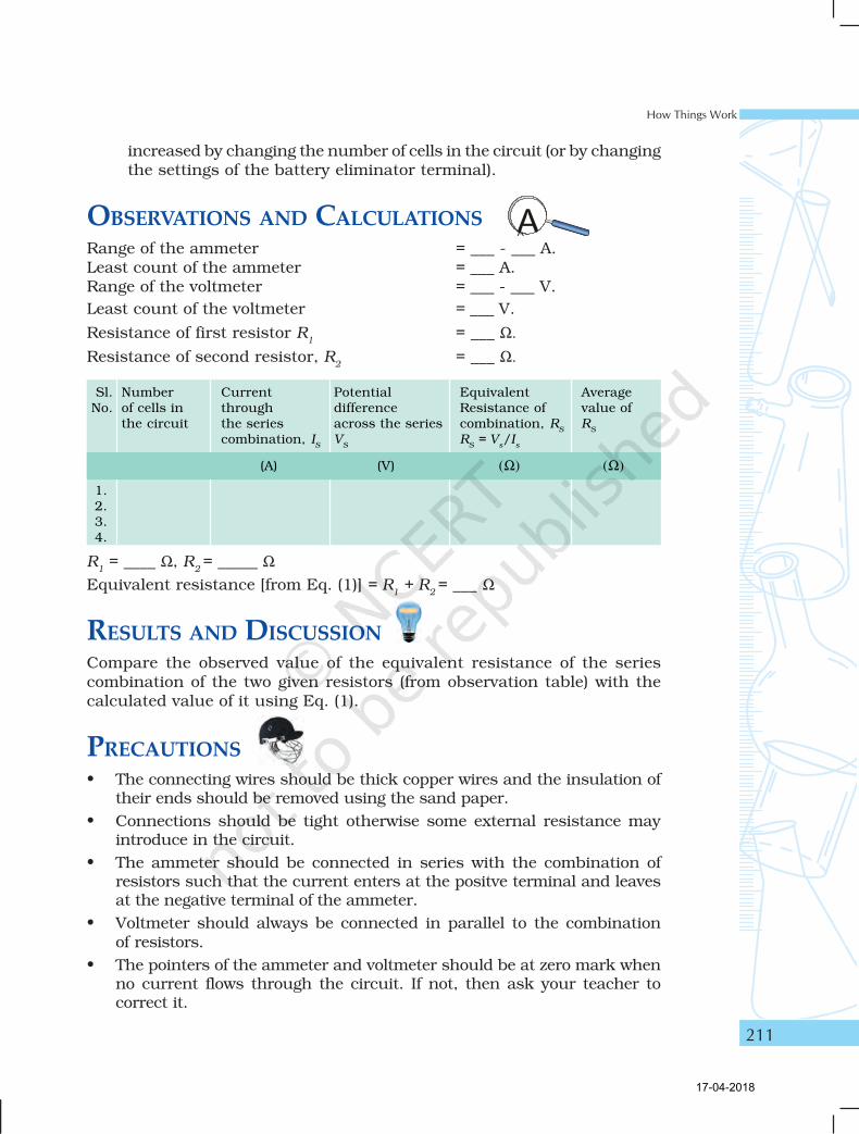
OBSERVATIONS AND CALCULATIONSRange of the ammeter = ___ - ___ A.Least count of the ammeter = ___ A.Range of the voltmeter = ___ - ___ V.
Least count of the voltmeter = ___ V.
Resistance of first resistor R1
= ___ Ω.
Resistance of second resistor, R2
= ___ Ω.
R1 = ____ Ω, R
2 = _____ Ω
Equivalent resistance [from Eq. (1)] = R1 + R
2 = ___ Ω
RESULTS AND DISCUSSIONCompare the observed value of the equivalent resistance of the seriescombination of the two given resistors (from observation table) with thecalculated value of it using Eq. (1).
PRECAUTIONS• The connecting wires should be thick copper wires and the insulation of
their ends should be removed using the sand paper.
• Connections should be tight otherwise some external resistance mayintroduce in the circuit.
• The ammeter should be connected in series with the combination ofresistors such that the current enters at the positve terminal and leavesat the negative terminal of the ammeter.
• Voltmeter should always be connected in parallel to the combinationof resistors.
• The pointers of the ammeter and voltmeter should be at zero mark whenno current flows through the circuit. If not, then ask your teacher tocorrect it.
Sl. Number Current Potential Equivalent AverageNo. of cells in through difference Resistance of value of
the circuit the series across the series combination, RS
RS
combination, IS
VS
RS = V
s/I
s
(A) (V) (Ω) (Ω)
1.2.3.4.
17-04-2018
Laboratory Manual Science
212
• Current should be passed through the circuit for a short time while takingobservations; otherwise current would cause unnecessary heating in thecircuit. Heating may change the resistance of resistors.
NOTE FOR THE TEACHER
• The internal resistance of cells should be much lower than theresistance of external resistors used in the experiment.
• In case if an accumulator or battery is used in place of cells oreliminator to draw the current in the circuit then a rheostat orvariable resistance box can be used to change the current flowingthrough the circuit.
• In case your school laboratory possesses the voltmeter andammeter of ranges other than the prescribed ranges, then theresistors may be chosen such that an appreciable deflection mayappear in the ammeter and voltmeter.
QUESTIONS• If two resistors having resistances of 2 Ω and 4 Ω, respectively
are connected in a series combination in an electric circuit, whatwill be the net resistance in the circuit?
• In an electric circuit, a resistor of 5 Ω resistance is connected toa battery (5 V) through an ammeter and a plug key. Now in thiscircuit an another resistor of 10 Ω is connected in series with the5 Ω resistor. Will there be any change in the ammeter reading?How much?
• In above question, what is the potential difference across the twoends of the resistor of 5 Ω resistance, when it is alone in thecircuit? What is the potential difference across the two ends ofresistor of 5 Ω resistance when it is connected in series with theresistor of 10 Ω resistance. What is the potential difference acrossthe series combination?
17-04-2018

How Things Work
213
AIMTo determine the equivalent resistance of two resistors connected in parallelcombination.
THEORYWhen two resistors of resistance R
1 and R
2 respectively are connected in a
parallel combination (Fig. 51.1), then their equivalent resistance Rp is
given by
21p R
1
R
1
R
1+=
or
21
21p
RR
RRR
+= (1)
In order to determine the resistance of a combinationof resistors connected in parallel, the current I
flowing through the circuit is measured with anammeter connected in series with the combination.The potential difference V across the combination ofresistors is measured with a voltmeter connected inparallel (Fig. 51.2).
E x p e r i m e n t 51
Fig. 51.1 : (a) Two resistors AB and
CD are placed side by
side; (b) Two resistors
AB and CD are
connected in a parallel
combination
17-04-2018
Laboratory Manual Science
214
MATERIALS REQUIREDTwo resistors of (each of 2 Ω resistance), an ammeter (range 0 – 5 A),a voltmeter (range 0 – 5 V), three dry cells of 1.5 V each with a cell holder(or a battery eliminator), a plug key, connecting wires, and a piece ofsand paper.
PROCEDURE1. Note the range and least count of the given ammeter and the
voltemeter.
2. Fresh connecting wires also have an insulating enamel layer at thetop. Similarly the connecting wires lying unused for some time mayalso develop an insulating layer. (How?) It is therefore important toclean the ends of connecting wires using a sand paper.
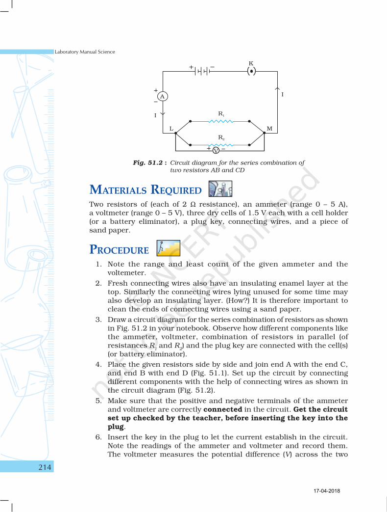
3. Draw a circuit diagram for the series combination of resistors as shownin Fig. 51.2 in your notebook. Observe how different components likethe ammeter, voltmeter, combination of resistors in parallel (ofresistances R
1 and R
2) and the plug key are connected with the cell(s)
(or battery eliminator).
4. Place the given resistors side by side and join end A with the end C,and end B with end D (Fig. 51.1). Set up the circuit by connectingdifferent components with the help of connecting wires as shown inthe circuit diagram (Fig. 51.2).
5. Make sure that the positive and negative terminals of the ammeterand voltmeter are correctly connected in the circuit. Get the circuitset up checked by the teacher, before inserting the key into theplug.
6. Insert the key in the plug to let the current establish in the circuit.Note the readings of the ammeter and voltmeter and record them.The voltmeter measures the potential difference (V) across the two
Fig. 51.2 : Circuit diagram for the series combination of
two resistors AB and CD
17-04-2018

How Things Work
215
Sl. Number Current Potential difference Equivalent Average value ofNo. of cells in through across the parallel Resistance of R
p
the circuit the parallel combination, Vp
combination, Rp
combination Rp = V
p/I
p
Ip (A) (V) () ()
1.
2.
3.
4.
ends A and D of the series combination of two resistors, and theammeter measures the current I through the series combination.Remove the key from the plug to avoid unnecessary heating of wires(How does it happen? Think it in accordance with the Joule’s law ofheating.)
7. Repeat the activity for three different values of current through thecircuit and record the readings of the ammeter and voltmeter in eachcase. The current through the circuit may either be decreased orincreased by changing the number of cells in the circuit (or by changingthe settings of the battery eliminator terminal).
OBSERVATIONS AND CALCULATIONS(i) Range of the ammeter = ____ - ____ A.(ii) Least count of the ammeter = ____ A.(iii) Range of the voltmeter = ____ - ____ V.(iv) Least count of the voltmeter = ____ V.
(v) Resistance of first resistor R1
= ____ (vi) Resistance of second resistor, R
2= ____
R1 = ____ , R
2= _____
Equivalent resistance [from Eq. (1)] =21
21
RR
RR
= ___
RESULTS AND DISCUSSIONCompare the observed value of the equivalent resistannce of the parallelcombination of the two given resistors (from observation table) with thecalculated value of it using Eq. (1).
17-04-2018
Laboratory Manual Science
216
PRECAUTIONS AND SOURCES OF ERROR• The connecting wires should be thick copper wires and the insulation of
their ends should be removed using the sand paper.
• Connections should be tight otherwise some contact resistance mayintroduce in the circuit.
• The ammeter should be connected in series with the combinations ofresistors such that the current enters at the positve terminal and leavesat the negative terminal of the ammeter.
• Voltmeter should always be connected in parallel to the combinations ofresistors.
• The pointers of the ammeter and voltmeter should be at zero mark whenno current through the circuit. If not, then ask your teacher to correct it.
• Current should be passed through the circuit for a short time whiletaking observations; otherwise current would cause unnecessary heatingin the circuit. Heating may change the resistance of resistors.
NOTE FOR THE TEACHER
• The internal resistance of cells should be much lower than theresistance of external resistors used in the experiment.
• In case an accumulator or battery is used in place of cells oreliminator to draw the current in the circuit then a rheostat orvariable resistance box can be used to change the current flowingthrough the circuit.
• In case your school laboratory possesses the voltmeter and ammeterof ranges other than the prescribed ranges, then the resistors maybe chosen such that an appreciable deflection may appear in theammeter and voltmeter.
QUESTIONS• If two resistors having resistances of 3 Ω, and 6 Ω, respectively are
connected in parallel, what will be the net resistance in the circuit?
• Two resistors having resistances of 4 Ω and 6 Ω, respectively areconnected in a circuit. It was found that the total resistance in thecircuit is less than 4 Ω. In what way the resistances would havebeen connected?
• Two resistors are connected in series and then in parallel. Whateffect will it have on the readings of voltmeter and ammeter?
• In what way household appliances should be connected?
17-04-2018
How Things Work
217
AIMTo draw magnetic field lines of a bar magnet.
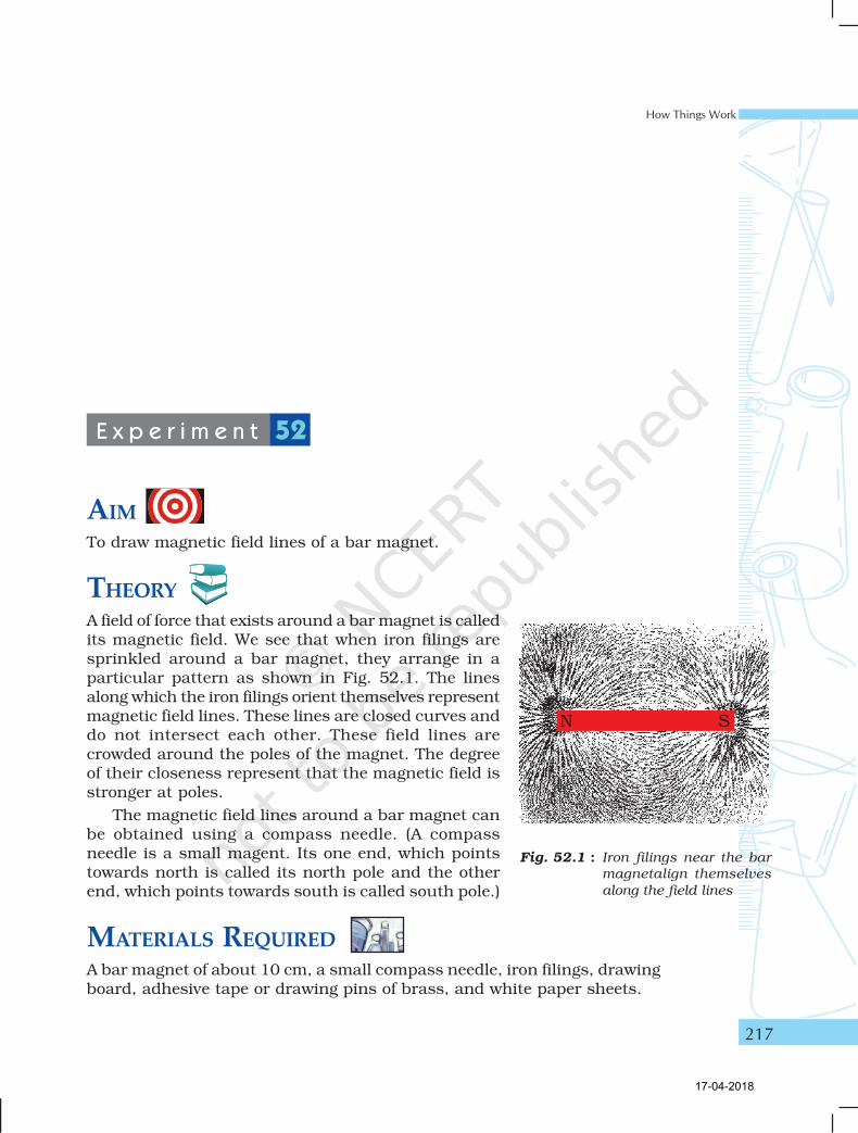
THEORYA field of force that exists around a bar magnet is calledits magnetic field. We see that when iron filings aresprinkled around a bar magnet, they arrange in aparticular pattern as shown in Fig. 52.1. The linesalong which the iron filings orient themselves representmagnetic field lines. These lines are closed curves anddo not intersect each other. These field lines arecrowded around the poles of the magnet. The degreeof their closeness represent that the magnetic field isstronger at poles.
The magnetic field lines around a bar magnet canbe obtained using a compass needle. (A compassneedle is a small magent. Its one end, which pointstowards north is called its north pole and the otherend, which points towards south is called south pole.)
MATERIALS REQUIREDA bar magnet of about 10 cm, a small compass needle, iron filings, drawingboard, adhesive tape or drawing pins of brass, and white paper sheets.
E x p e r i m e n t 52
Fig. 52.1 : Iron filings near the bar
magnetalign themselves
along the field lines
17-04-2018
Laboratory Manual Science
218
PROCEDURE
(a) To observe the pattern of iron filings around a bar magnet
1. Fix a sheet of white paper on a drawing board using adhesive tape ordrawing pins of brass.
2. Place a bar magnet on this sheet in the middle of it.
3. Sprinkle iron filings around the bar magnet and gently tap the drawingboard till a pattern, as shown in Fig. 52.1, is formed.
4. Observe the pattern. What does it show? Notice that the iron filingsare crowded around the poles of the bar magnet.
5. Remove the iron filings from the paper.
(b) To draw the magnetic field lines around a bar magnet
6. Identify the north and south poles of the bar magnet. Place the barmagnet in the middle of the paper. Mark the position of north andsouth poles and also draw the boundary of the bar magnet.
7. Place a small compass needlevery near the north pole of themagnet.
8. You will observe that thesouth end of the compassneedle aligns itself towardsthe north pole of the barmagnet.
9. Mark the positions of its twoends of the compass needle.
10. Move the compass to a newposition such that its southend occupies the positionpreviously occupied by itsnorth pole.
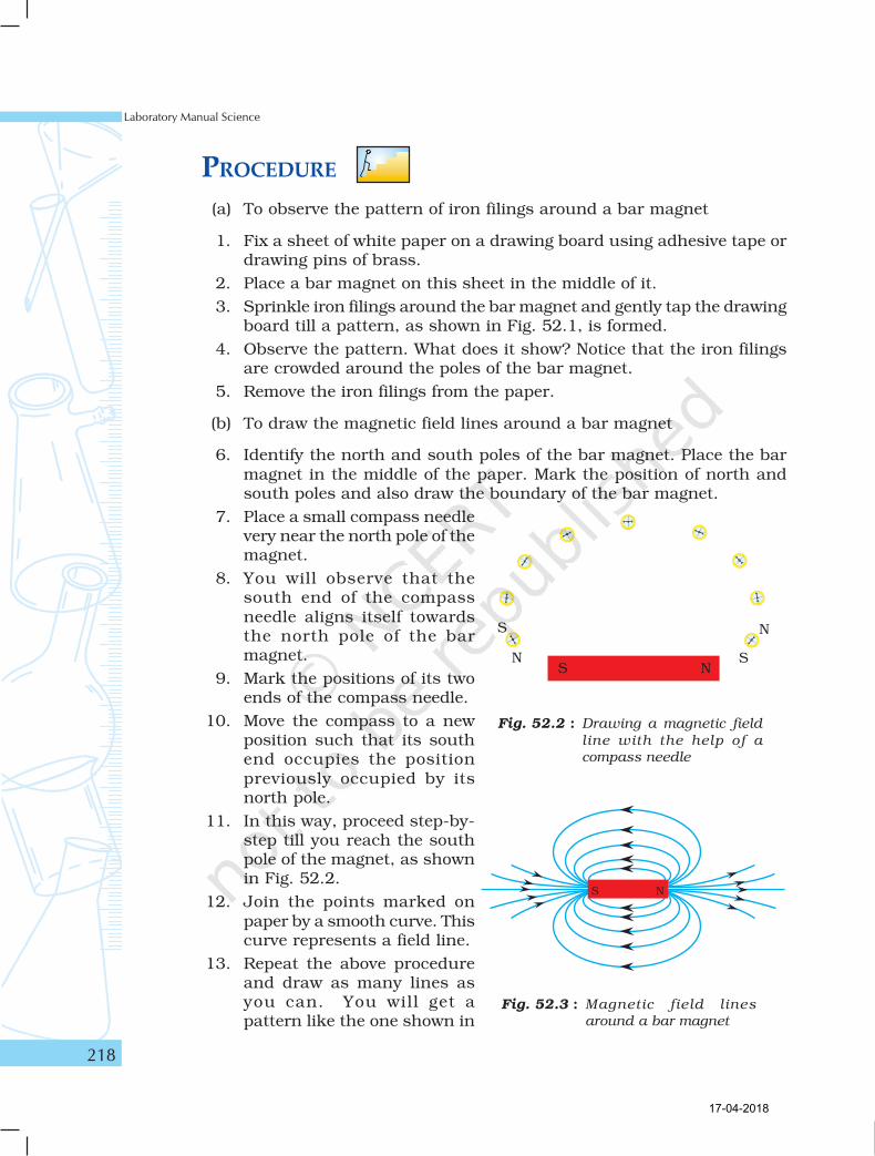
11. In this way, proceed step-by-step till you reach the southpole of the magnet, as shownin Fig. 52.2.
12. Join the points marked onpaper by a smooth curve. Thiscurve represents a field line.
13. Repeat the above procedureand draw as many lines asyou can. You will get apattern like the one shown in
Fig. 52.2 : Drawing a magnetic field
line with the help of a
compass needle
Fig. 52.3 : Magnetic field lines
around a bar magnet
17-04-2018
How Things Work
219
Fig. 52.3. You might have noticed that the deflection in the compassneedle is more when it is placed closer to one of the poles of themagnet.
OBSERVATIONS AND CALCULATIONSThe attached paper sheet shows the pattern of magnetic field lines drawnaround the bar magnet.
RESULTS AND DISCUSSIONFrom the magnetic field lines around a bar magnet, it may beconfirmed that:
• the magnetic field lines are closed and continous;
• the deflection in compass needle increases as it is moves towards thepoles;
• two magnetic field lines do not intersect; and
• the magnetic field lines are crowded at poles of the bar magnet.
PRECAUTIONS• There should not be any other magnetic material near the bar magnet
except the compass needle while drawing the magnetic field lines.
• Size of the compass needle should be small.
• The bar magnet should be sufficiently strong to produce an appreciabledeflection in the compass needle placed at a distance of 15 cm from thebar magnet.
NOTE FOR THE TEACHER
• If it is found that this experiment, as explained, is difficult toperform within the given time, it may be suggested to draw themagnetic field lines only. The first part to observe the pattern ofiron filings around a bar magnet may be skipped.
• North and south poles of a bar magnet can be identified usinganother magnet of known polarity.
• A small compass needle should be used for drawing the fieldlines so that sufficient number of field lines can be drawn on asheet of paper.
• It is advised to place the north and south poles of the bar magnetin the north-south direction. This is to avoid the variation in fieldpatterns due to the effect of earth’s magnetic field.
17-04-2018
Laboratory Manual Science
220
APPLICATIONSThis method can be used to identify the magnetic materials. The strengthsof two bar magnets can also be compared.
QUESTIONS• You are provided an iron strip and a bar magnet. How will you
distinguish them?
• How does a compass needle work?
• How will you make a compass using an iron needle, piece ofthermo-cole and a magnet?
• Do you think that the needle of a compass is a magnet?
• Why does the needle of a compass point north and south?
• Can an ordinary magnet be used as a compass?
• What does degree of closeness of magnetic field lines indicate?
• Why are more iron filings concentrated around the poles of themagnets?
• In this experiment it is advised to use a small compass needle.What will happen if small compass needle is replaced with a bigsize compass needle?
17-04-2018
How Things Work
221
AIMTo draw the magnetic field lines of a current-carrying straight wire.
THEORYAn electric current through a wire (conductor) produces a magnetic fieldaround it. The existance of magnetic field can be observed using a magneticcompass needle. The direction of the magnetic field depends on the directionof the current through the wire. In this experiment we shall make an attemptto draw the magnetic field lines of a current carrying straight wire and findthe effect of change of direction of current through the wire on the magneticfield lines.
MATERIALS REQUIREDA battery (12 V) or a battery eliminator (12 V/2 A), a variable resistance (arehostat), a plug key, a thick copper wire (prefereably SWG-12) of about 50cm length, a rectangular wooden plank with a small hole at the centrethrough which the thick copper wire may comfortably pass, ammeter (0 - 3A), a white sheet, a small compass needle, a wooden stand, adhesive tape,connecting wires, and a piece of sand paper.
PROCEDURE1. Note the range and least count of the given ammeter.
2. Fresh connecting wires also have an insulating enamel layer at thetop. Similarly the connecting wires lying unused for some time may
E x p e r i m e n t 53
17-04-2018
Laboratory Manual Science
222
also develop an insulating layer. It is therefore important to clean theends of connecting wires using a sand paper.
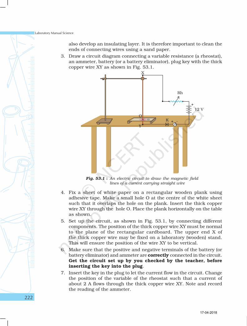
3. Draw a circuit diagram connecting a variable resistance (a rheostat),an ammeter, battery (or a battery eliminator), plug key with the thickcopper wire XY as shown in Fig. 53.1.
Fig. 53.1 : An electric circuit to draw the magnetic field
lines of a current carrying straight wire
4. Fix a sheet of white paper on a rectangular wooden plank usingadhesive tape. Make a small hole O at the centre of the white sheetsuch that it overlaps the hole on the plank. Insert the thick copperwire XY through the hole O. Place the plank horizontally on the tableas shown.
5. Set up the circuit, as shown in Fig. 53.1, by connecting differentcomponents. The position of the thick copper wire XY must be normalto the plane of the rectangular cardboard. The upper end X ofthe thick copper wire may be fixed on a laboratory (wooden) stand.This will ensure the position of the wire XY to be vertical.
6. Make sure that the positive and negative terminals of the battery (orbattery eliminator) and ammeter are correctly connected in the circuit.Get the circuit set up by you checked by the teacher, beforeinserting the key into the plug.
7. Insert the key in the plug to let the current flow in the circuit. Changethe position of the variable of the rheostat such that a current ofabout 2 A flows through the thick copper wire XY. Note and recordthe reading of the ammeter.
17-04-2018
How Things Work
223
8. Place a compass at a point (say P) over the white sheet placed on therectangular cardboard. Observe the direction of the compass needle.By convention, the direction of the north pole of the compass needlewould give the direction of the magnetic field produced by the electriccurrent through the straight wire at point P.
9. Mark the position of the compass needle’s two ends and move thecompass so that its south end occupies the position previouslyoccupied by its noth end. Again mark the new positions indicated bythe two ends of the compass needle. In this way proceed step-by-steptill you get a complete circle as shown in Fig 53.1. Also mark thedirection of the magnetic field line by an arrow. Thus the magneticfield line of a current carrying straight wire is a circle having thecentre at position of the current carrying wire.
10. After drawing one magnetic field line remove the plug key and waitfor few minutes so that the wire comes back to its normal temperature.
11. Repeat the above procedure and draw as many concentric circles(representing magnetic field lines) as you can. What happens to thedeflection of the needle if the compass is moved away from the thickcopper wire. Do you observe that the deflection in the compass needledecreases? What does it mean? It represents that the magnetic fieldproduced by a given current in the conductor decreases as the distancefrom it increases.
12. Using this circuit, you can also see the effect of change in currentthrough the conductor on the deflection in the compass needle placedat a given point. For this, place the compass needle at a fixed point Q(say). Now by changing the position of the variable contact of therheostat, increase the current through the thick copper wire. Whateffect do you observe? The deflection in the compass needle alsoincreases. Do you observe a decrease in the compass needle at agiven point Q (say) with a decrease in current through the thick copperwire. It indicates that the magnitude of the magnetic field producedat a given point increases as the current through the thick copperwire increases or vice-versa.
13. Reverse the direction of current through the straight thick copperwire by interchanging the terminals of the battery (or batteryeliminator) and observe the direction of the compass needle. Does itget reversed?
OBSERVATIONSThe attached sheet shows the pattern of magnetic field lines around acurrent-carying straight wire.
17-04-2018
Laboratory Manual Science
224
RESULTS AND DISCUSSIONOn the basis of observations on the magnetic field lines, the followingcan be infered:
• The magnetic field lines around a current-carrying straight wire donot intersect each other.
• The deflection in the compass needle decreases as it is moved awayfrom the current carrying straight wire.
• The deflection in the compass needle changes as the current throughthe wire changes.
• The direction of magnetic field lines gets reversed if the direction ofcurrent through the straight copper wire is reversed.
PRECAUTIONS• Plug key should only be inserted in the circuit when you are recording
the observations.
• After drawing one magnetic field line remove the plug key and wait forfew minutes so that the wire comes back to its normal temperature.
• Please do not touch the hot wire during the experiment, lest you mayhurt yourself as the wire may become very hot.
• There should not be any magnetic material near the current carryingstraight wire except the compass needle.
• The thick copper wire XY must be positioned straight and verticalthrough out the experiment. In case a proper wooden stand is notavailable, then the wire must be passed through a cork that can beclamped in the laboratory stand.
• A resistor of variable resistance (variable resistor) or rheostat shouldbe connected in series with the thick straight copper wire to regulatethe current through the straight copper wire.
NOTE FOR THE TEACHER
• In this experiment a variable resistance (a rheostat) is used tochange the resistance in the circuit and thereby to change thecurrent through the circuit. A rheostat may be a new instrumentfor the students. It is suggested to demonstarte its use as a variableresistor. However in place of a rheostat, a resistance box mayalso be used in the circuit.
• In this experiment, a high current (about 2 A) is required to flowthrough the circuit for a longer time. Thus the amount of heatgenerated will be more (Joule’s law of heating). A thin wire maynot remain straight for the entire duration of the experiment and
17-04-2018
How Things Work
225
may even melt. It is therefore advised to use a thick copperwire (preferably SWG-12) whose diameter is about 2 mm. Incase if it is not available, other wires may also be used. Suchthick copper wires are often used in the earthing of domesticelectric circuits.
• In this experiment, a relatively higher current flows throughthe circuit and for this reacson, it requires a high voltagebattery or a high capacity battery eliminator.
QUESTIONS• How magnetic field lines of a straight current carrying wire
are different from the field lines of a bar magnet?
• What affect you will notice on the pattern of field lines if youinterchange a rheostat by the plug key in this experimentalarrangement?
• How can the direction of the magnetic field be determined? Suggestone method.
• What will happen to the pattern of field lines if the thick copperwire is kept horizontally straight instead of vertically straight?Discuss in groups.
17-04-2018
Laboratory Manual Science
226
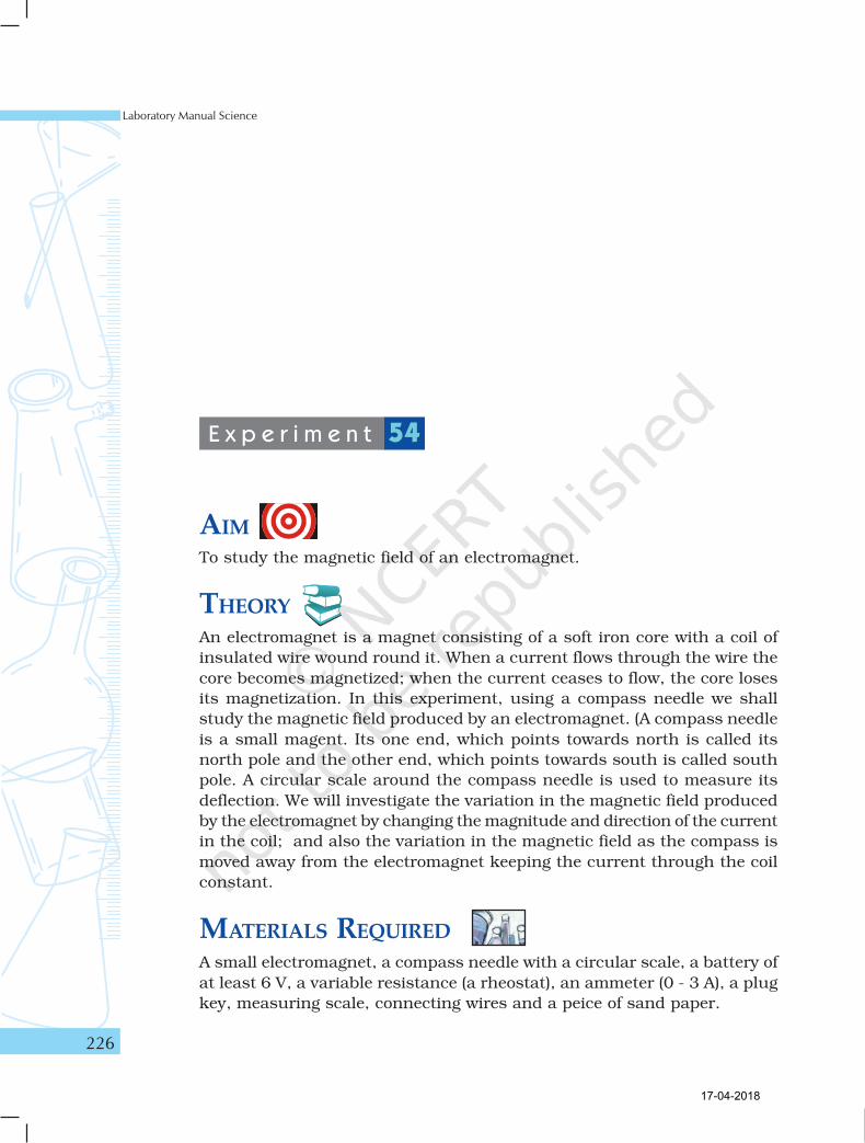
AIMTo study the magnetic field of an electromagnet.
THEORY
An electromagnet is a magnet consisting of a soft iron core with a coil of
insulated wire wound round it. When a current flows through the wire the
core becomes magnetized; when the current ceases to flow, the core loses
its magnetization. In this experiment, using a compass needle we shall
study the magnetic field produced by an electromagnet. (A compass needle
is a small magent. Its one end, which points towards north is called its
north pole and the other end, which points towards south is called south
pole. A circular scale around the compass needle is used to measure its
deflection. We will investigate the variation in the magnetic field produced
by the electromagnet by changing the magnitude and direction of the current
in the coil; and also the variation in the magnetic field as the compass is
moved away from the electromagnet keeping the current through the coil
constant.
MATERIALS REQUIRED
A small electromagnet, a compass needle with a circular scale, a battery of
at least 6 V, a variable resistance (a rheostat), an ammeter (0 - 3 A), a plug
key, measuring scale, connecting wires and a peice of sand paper.
E x p e r i m e n t 54
17-04-2018
How Things Work
227
PROCEDURE1. Note the range and least count of the given ammeter.
2. Clean connecting wires using the sand paper.
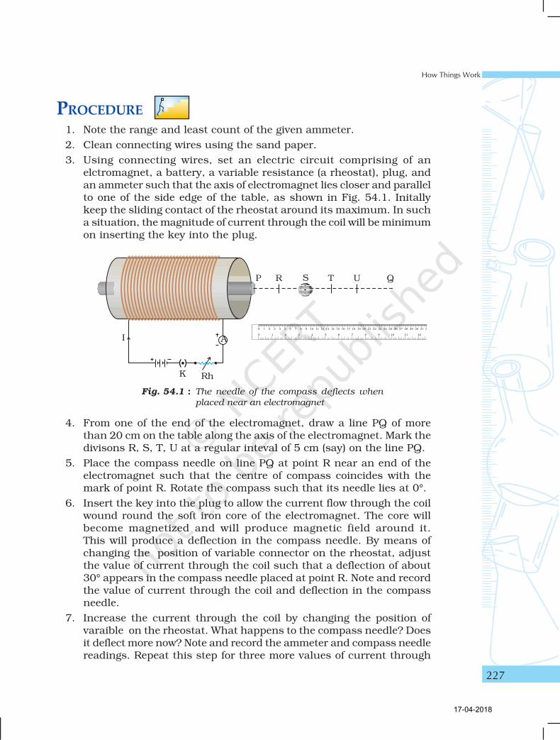
3. Using connecting wires, set an electric circuit comprising of anelctromagnet, a battery, a variable resistance (a rheostat), plug, andan ammeter such that the axis of electromagnet lies closer and parallelto one of the side edge of the table, as shown in Fig. 54.1. Initallykeep the sliding contact of the rheostat around its maximum. In sucha situation, the magnitude of current through the coil will be minimumon inserting the key into the plug.
Fig. 54.1 : The needle of the compass deflects when
placed near an electromagnet
4. From one of the end of the electromagnet, draw a line PQ of morethan 20 cm on the table along the axis of the electromagnet. Mark thedivisons R, S, T, U at a regular inteval of 5 cm (say) on the line PQ.
5. Place the compass needle on line PQ at point R near an end of theelectromagnet such that the centre of compass coincides with themark of point R. Rotate the compass such that its needle lies at 0°.
6. Insert the key into the plug to allow the current flow through the coilwound round the soft iron core of the electromagnet. The core willbecome magnetized and will produce magnetic field around it.This will produce a deflection in the compass needle. By means ofchanging the position of variable connector on the rheostat, adjustthe value of current through the coil such that a deflection of about30° appears in the compass needle placed at point R. Note and recordthe value of current through the coil and deflection in the compassneedle.
7. Increase the current through the coil by changing the position ofvaraible on the rheostat. What happens to the compass needle? Doesit deflect more now? Note and record the ammeter and compass needlereadings. Repeat this step for three more values of current through
17-04-2018
Laboratory Manual Science
228
the coil. Keep the current in the coil such that it does not produce adeflection more than 60° in the compass needle. Remove the key fromthe plug.
8. To change the direction of the current through the coil, interchangethe connections of battery terminals. Observe the change in thedeflection of the compass needle.
9. Insert the key into the plug. Again note and record the current throughthe coil and deflection in the compass needle placed at point R alongthe axis PQ of the elctromagnet. Remove the key from the plug.
10. Move the compass needle to position S. Ensure that the compassneedle lies at 0°. Insert the key into the plug and observe the deflectionin the compass needle. Now the compass needle is placed at a distanceof 10 cm from the end P of the electromagnet. Observe and record thedeflection in the compass needle when placed at different distancesfrom the end P of the electromagnet. That is when the compass needleis placed at points T, U etc. Remove the key from the plug.
11. In this experiment, you might have drawn a few lines on the table.As a courtsey to your friends who might perform this experimentlater, please clean the table.
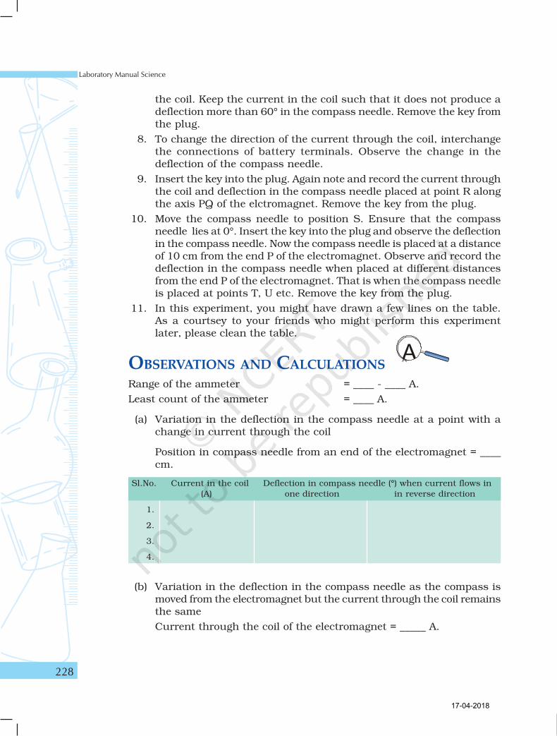
OBSERVATIONS AND CALCULATIONSRange of the ammeter = ____ - ____ A.
Least count of the ammeter = ____ A.
(a) Variation in the deflection in the compass needle at a point with achange in current through the coil
Position in compass needle from an end of the electromagnet = ____cm.
(b) Variation in the deflection in the compass needle as the compass ismoved from the electromagnet but the current through the coil remainsthe same
Current through the coil of the electromagnet = _____ A.
Sl.No. Current in the coil Deflection in compass needle (°) when current flows in
(A) one direction in reverse direction
1.
2.
3.
4.
17-04-2018
How Things Work
229
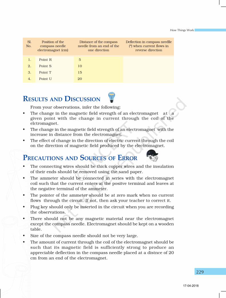
Sl. Position of the Distance of the compass Deflection in compass needlleNo. compass needle needle from an end of the (°) when current flows in
electromagnet (cm) one direction reverse direction
1. Point R 5
2. Point S 10
3. Point T 15
4. Point U 20
RESULTS AND DISCUSSIONFrom your observations, infer the following:
• The change in the magnetic field strength of an electromagnet at agiven point with the change in current through the coil of theelctromagnet.
• The change in the magnetic field strength of an electromagnet with theincrease in distance from the electromagnet.
• The effect of change in the direction of electric current through the coilon the direction of magnetic field produced by the electromagnet.
PRECAUTIONS AND SOURCES OF ERROR
• The connecting wires should be thick copper wires and the insulation
of their ends should be removed using the sand paper.
• The ammeter should be connected in series with the electromagnet
coil such that the current enters at the positve terminal and leaves at
the negative terminal of the ammeter.
• The pointer of the ammeter should be at zero mark when no current
flows through the circuit. If not, then ask your teacher to correct it.
• Plug key should only be inserted in the circuit when you are recording
the observations.
• There should not be any magnetic material near the electromagnet
except the compass needle. Electromagnet should be kept on a wooden
table.
• Size of the compass needle should not be very large.
• The amount of current through the coil of the electromagnet should be
such that its magnetic field is sufficiently strong to produce an
appreciable deflection in the compass needle placed at a distnce of 20
cm from an end of the electromagnet.
17-04-2018
Laboratory Manual Science
230
NOTE FOR THE TEACHER• In this experiment a variable resistance (a rheostat) is used to
change the resistance in the circuit and thereby to change thecurrent through the coil of the electromagnet. A rheostat may bea new instrument for the students. It is suggested to expose themto use it before they opt for this experiment. However in place ofa rheostat, a resistance box may also be used in the electric circuit.
• In this experiment, a relatively higher current flows through thecircuit and for this reason, it requires a high voltage battery or ahigh capacity battery eliminator.
• An electromagnet can be improvised in a school laboratory. Nearlyforty turns of insulated thick copper wire (preferably SWG-18 orSWG-20) may be closely wrapped on a soft iron core. When anelectric current is passed through the copper wire, the soft ironcore gets magnetized and produces a magnetic field around it.The magnetic field produced is directly proportional to numberof wrapped turns and the electric current passing through it.
QUESTIONS• How can you make a simple electromagnet?
• Can you think of an electromagnet that is capable of producingstronger magnetic field than the magnetic field froduced by anypermanent magnet?
• How does a current carrying coil of insulated copper wire woundround on a soft iron core affects a compass needle placed near toit?
• Name two ways to increase the strength of magnetic field producedby an electromagnet.
• What factors affect the strength of electromagnet?
17-04-2018
How Things Work
231
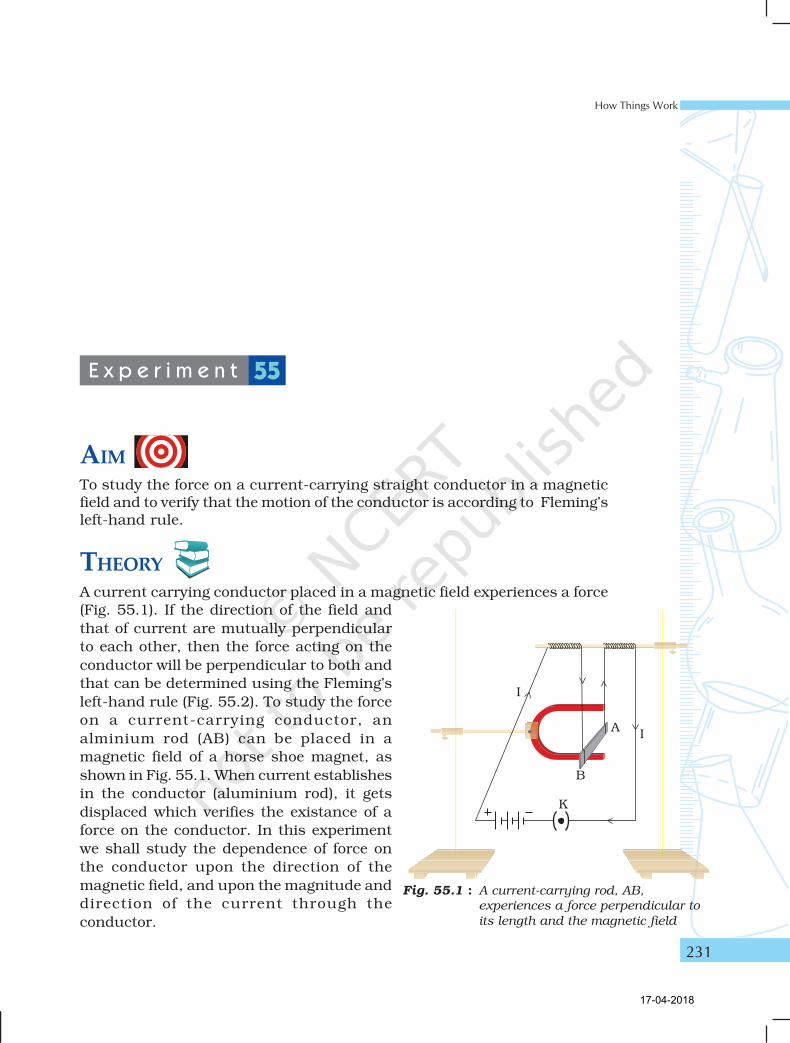
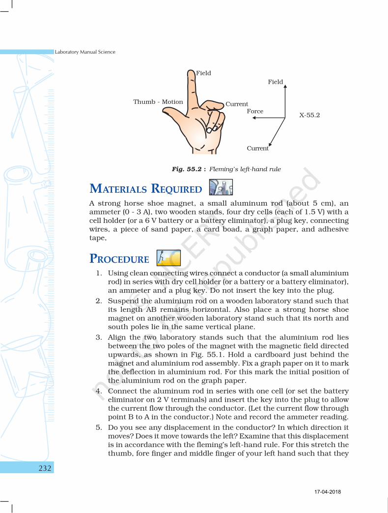
AIMTo study the force on a current-carrying straight conductor in a magneticfield and to verify that the motion of the conductor is according to Fleming’sleft-hand rule.
THEORYA current carrying conductor placed in a magnetic field experiences a force
(Fig. 55.1). If the direction of the field and
that of current are mutually perpendicular
to each other, then the force acting on the
conductor will be perpendicular to both and
that can be determined using the Fleming’s
left-hand rule (Fig. 55.2). To study the force
on a current-carrying conductor, an
alminium rod (AB) can be placed in a
magnetic field of a horse shoe magnet, as
shown in Fig. 55.1. When current establishes
in the conductor (aluminium rod), it gets
displaced which verifies the existance of a
force on the conductor. In this experiment
we shall study the dependence of force on
the conductor upon the direction of the
magnetic field, and upon the magnitude and
direction of the current through the
conductor.
E x p e r i m e n t 55
Fig. 55.1 : A current-carrying rod, AB,
experiences a force perpendicular to
its length and the magnetic field
17-04-2018
Laboratory Manual Science
232
MATERIALS REQUIREDA strong horse shoe magnet, a small aluminum rod (about 5 cm), anammeter (0 - 3 A), two wooden stands, four dry cells (each of 1.5 V) with acell holder (or a 6 V battery or a battery eliminator), a plug key, connectingwires, a piece of sand paper, a card boad, a graph paper, and adhesivetape,
PROCEDURE1. Using clean connecting wires connect a conductor (a small aluminium
rod) in series with dry cell holder (or a battery or a battery eliminator),an ammeter and a plug key. Do not insert the key into the plug.
2. Suspend the aluminium rod on a wooden laboratory stand such thatits length AB remains horizontal. Also place a strong horse shoemagnet on another wooden laboratory stand such that its north andsouth poles lie in the same vertical plane.
3. Align the two laboratory stands such that the aluminium rod liesbetween the two poles of the magnet with the magnetic field directedupwards, as shown in Fig. 55.1. Hold a cardboard just behind themagnet and aluminium rod assembly. Fix a graph paper on it to markthe deflection in aluminium rod. For this mark the initial position ofthe aluminium rod on the graph paper.
4. Connect the aluminum rod in series with one cell (or set the batteryeliminator on 2 V terminals) and insert the key into the plug to allowthe current flow through the conductor. (Let the current flow throughpoint B to A in the conductor.) Note and record the ammeter reading.
5. Do you see any displacement in the conductor? In which direction itmoves? Does it move towards the left? Examine that this displacementis in accordance with the fleming’s left-hand rule. For this stretch thethumb, fore finger and middle finger of your left hand such that they
Fig. 55.2 : Fleming’s left-hand rule
Thumb - Motion
Field
CurrentForce
Field
Current
17-04-2018
How Things Work
233
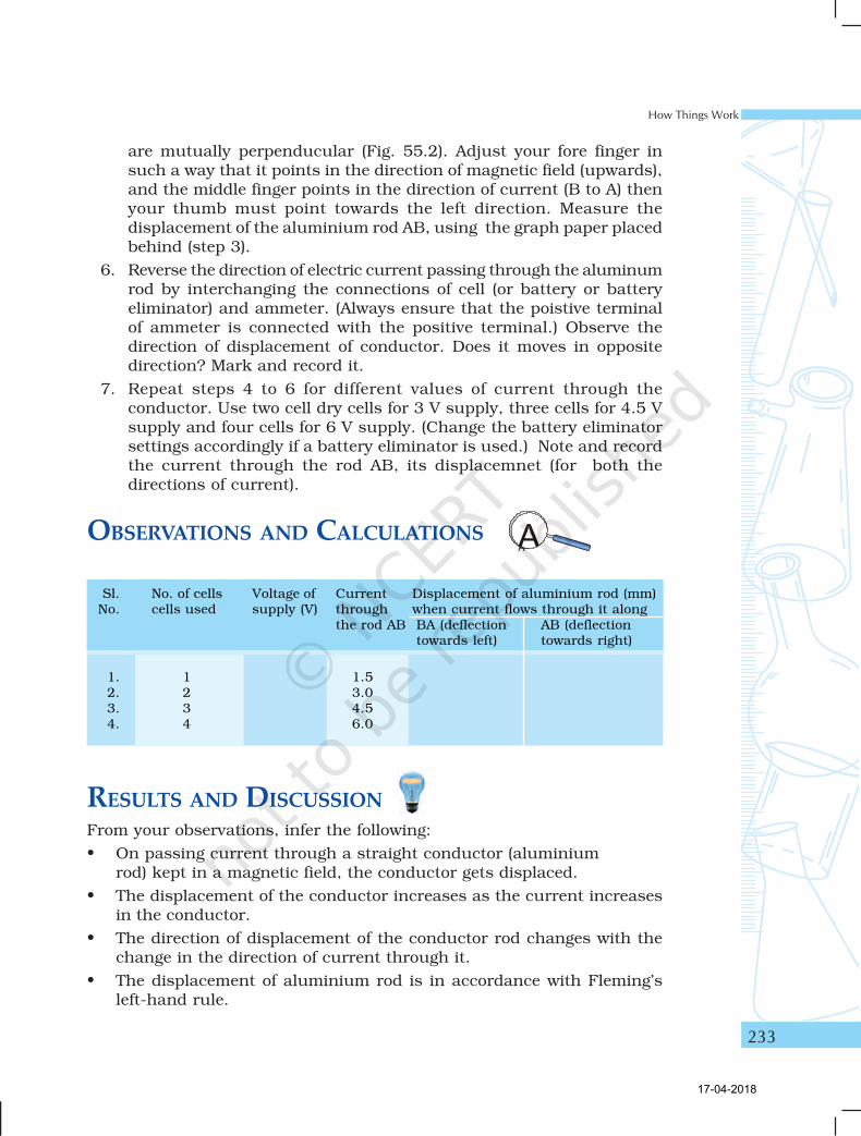
Sl. No. of cells Voltage of Current Displacement of aluminium rod (mm)No. cells used supply (V) through when current flows through it along
the rod AB BA (deflection AB (deflectiontowards left) towards right)
1. 1 1.52. 2 3.03. 3 4.54. 4 6.0
are mutually perpenducular (Fig. 55.2). Adjust your fore finger insuch a way that it points in the direction of magnetic field (upwards),and the middle finger points in the direction of current (B to A) thenyour thumb must point towards the left direction. Measure thedisplacement of the aluminium rod AB, using the graph paper placedbehind (step 3).
6. Reverse the direction of electric current passing through the aluminumrod by interchanging the connections of cell (or battery or batteryeliminator) and ammeter. (Always ensure that the poistive terminalof ammeter is connected with the positive terminal.) Observe thedirection of displacement of conductor. Does it moves in oppositedirection? Mark and record it.
7. Repeat steps 4 to 6 for different values of current through theconductor. Use two cell dry cells for 3 V supply, three cells for 4.5 Vsupply and four cells for 6 V supply. (Change the battery eliminatorsettings accordingly if a battery eliminator is used.) Note and recordthe current through the rod AB, its displacemnet (for both thedirections of current).
OBSERVATIONS AND CALCULATIONS
RESULTS AND DISCUSSIONFrom your observations, infer the following:
• On passing current through a straight conductor (aluminiumrod) kept in a magnetic field, the conductor gets displaced.
• The displacement of the conductor increases as the current increasesin the conductor.
• The direction of displacement of the conductor rod changes with thechange in the direction of current through it.
• The displacement of aluminium rod is in accordance with Fleming’sleft-hand rule.
17-04-2018
Laboratory Manual Science
234
PRECAUTIONS• Clean the ends of the connecting wire using a sand paper to remove
the insulating layer from them.
• Aluminium rod (AB) should be suspended in such a way that it shouldnot touch the horse shoe magnet.
• Horse shoe magnet should be fixed a using wooden stand.
• There should not be any other magnetic material near the experimentalset-up.
• Plug key should be inserted in the circuit only at the time of recordingthe observations.
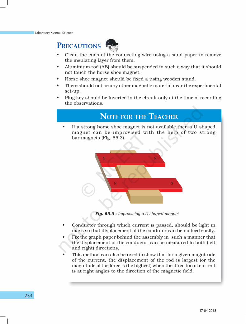
NOTE FOR THE TEACHER
• If a strong horse shoe magnet is not available then a U-shapedmagnet can be improvised with the help of two strongbar magnets (Fig. 55.3).
Fig. 55.3 : Improvising a U-shaped magnet
• Conductor through which current is passed, should be light inmass so that displacement of the condutor can be noticed easily.
• Fix the graph paper behind the assembly in such a manner thatthe displacement of the conductor can be measured in both (leftand right) directions.
• This method can also be used to show that for a given magnitudeof the current, the displacement of the rod is largest (or themagnitude of the force is the highest) when the direction of currentis at right angles to the direction of the magnetic field.
17-04-2018
How Things Work
235
QUESTIONS• Why does the aluminum rod get displaced in this experiment ?
• List the devices used in our everyday life that use current-carryingconductors.
• What do you expect if the position of horseshoe magnet and thealuminium rod are interchanged in this experiment.
17-04-2018
Laboratory Manual Science
236
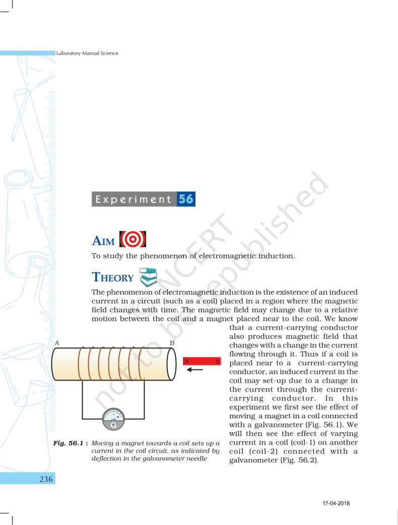
AIMTo study the phenomenon of electromagnetic induction.
THEORYThe phenomenon of electromagnetic induction is the existence of an inducedcurrent in a circuit (such as a coil) placed in a region where the magneticfield changes with time. The magnetic field may change due to a relativemotion between the coil and a magnet placed near to the coil. We know
that a current-carrying conductoralso produces magnetic field thatchanges with a change in the currentflowing through it. Thus if a coil isplaced near to a current-carryingconductor, an induced current in thecoil may set-up due to a change inthe current through the current-carrying conductor. In thisexperiment we first see the effect ofmoving a magnet in a coil connectedwith a galvanometer (Fig. 56.1). Wewill then see the effect of varyingcurrent in a coil (coil-1) on anothercoil (coil-2) connected with agalvanometer (Fig. 56.2).
E x p e r i m e n t 56
Fig. 56.1 : Moving a magnet towards a coil sets up a
current in the coil circuit, as indicated by
deflection in the galvanometer needle
17-04-2018
How Things Work
237
MATERIALS REQUIREDTwo coils of copper wire each having about 50 turns, a rheostat (variableresistor), an ammeter (0 - 3 A), a galvanometer, a strong bar magnet, aplug key, connecting wires, and a piece of sand paper.
PROCEDURE
A. Existance of induced current in a coil due to the relative motion
between a coil and magnet
1. Take a coil AB and connect it with a galvanometer as shown in
Fig. 56.1.
2. Take a strong bar magnet and move its north pole (or south pole)
towards an end (say B) of the coil. Observe the position of needle of
galvanometer. Is there any deflection in it? There is a momentary
deflection in the galvanometer needle in one direction (say in right
direction). What does this indicate? This indicates the presence of a
current in the coil AB.
3. Stop moving the bar magnet. What do you observe now? Does the
galvanometer shows any reading? No. The deflection of the
galvanometer becomes zero when the motion of the bar magnet stops.
What does it mean?
4. Now withdraw the north pole of the magnet away from the coil and
observe the deflection in galvanometer. The galvanometer needle now
deflects in the opposite side (that is in left side), depicting that the
current is now set up in the direction opposite to the first.
5. Move South Pole of the magnet towards the end B of the coil and
observe the deflection in the galvanometer needle.
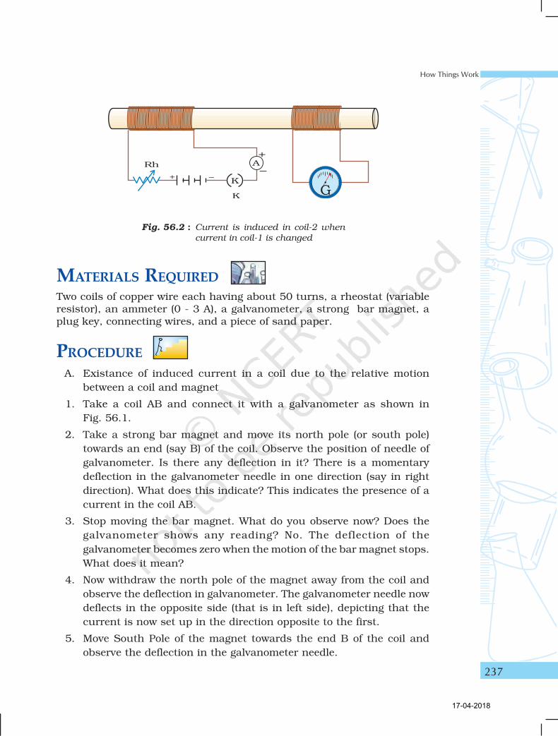
Fig. 56.2 : Current is induced in coil-2 when
current in coil-1 is changed
17-04-2018
Laboratory Manual Science
238
6. Place the magnet stationary at a point near to the coil retaining its
north pole towards the end B of the coil and observe it. The
galvanometer needle deflects towards the right when the coil is moved
towards the north pole of the magnet. Similarly, the needle moves
towards the left when the coil is moved away. Deflection of
galvanometer drops to zero when coil is kept stationary.
7. Finally keep the coil and the magnet both stationery and observe the
deflection. There is no deflection in the galvanometer. It is thus clear
that motion of a magnet with respect to the coil produces an induced
potential difference which sets up an induced electric current in the
circuit as has been noticed by the deflection of galvanometer in above
steps. Record your observations.
B. Existance of induced current in a coil due to a change in the current
through another coil placed close to it
8. Connect a coil (coil-1, say) of copper wire with a source (a cell or a
battery), through a rheostat, an ammeter and a plug key, as shown in
Fig. 56.2. Use clean connecting wires to make the circuit.
9. Bring another coil (coil-2) connected with a galvanometer close to the
coil-1 circuit.
10. Plug the key and allow a current to flow through coil-1. What do you
observe? Does the galvanometer needle connected with coil-2 deflects.
Yes it momentarily deflects. It stops at the zero mark as soon as the
current in coil-1 becomes steady. (Adjust the variable connector of
the rheostat to allow an appreciable current to flow through the coil-
1. Note that a rheostat is basically a resistor of variable resistance. It
is connected in series in a circuit to change the resistance in the
circuit.)
11. Change the current through coil-1, by moving the variable slider on
the rheostat coil. What do you observe? Do you see that the
galvanometer connected with coil-2, shows deflection in one direction
when current in coil-1 circuit increases while the deflection in
galvanometer needle reverses when the current in coil-1 circuit
decreases.
12. Record your observations in the observation table.
17-04-2018
How Things Work
239
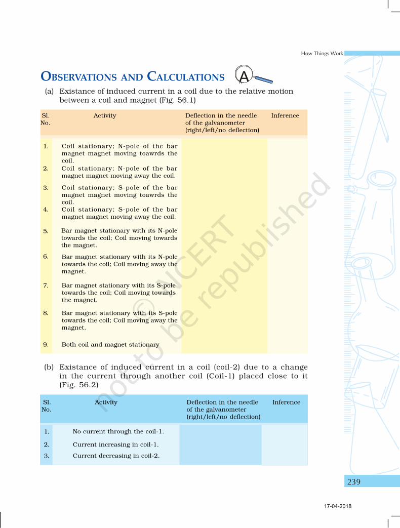
Sl. Activity Deflection in the needle InferenceNo. of the galvanometer
(right/left/no deflection)
Coil stationary; N-pole of the barmagnet magnet moving toawrds thecoil.
Coil stationary; N-pole of the barmagnet magnet moving away the coil.
Coil stationary; S-pole of the barmagnet magnet moving toawrds thecoil.Coil stationary; S-pole of the barmagnet magnet moving away the coil.
Bar magnet stationary with its N-poletowards the coil; Coil moving towardsthe magnet.
Bar magnet stationary with its N-poletowards the coil; Coil moving away themagnet.
Bar magnet stationary with its S-poletowards the coil; Coil moving towardsthe magnet.
Bar magnet stationary with its S-poletowards the coil; Coil moving away themagnet.
Both coil and magnet stationary
Sl. Activity Deflection in the needle InferenceNo. of the galvanometer
(right/left/no deflection)
No current through the coil-1.
Current increasing in coil-1.
Current decreasing in coil-2.
OBSERVATIONS AND CALCULATIONS(a) Existance of induced current in a coil due to the relative motion
between a coil and magnet (Fig. 56.1)
(b) Existance of induced current in a coil (coil-2) due to a changein the current through another coil (Coil-1) placed close to it(Fig. 56.2)
1.
2.
3.
4.
5.
6.
7.
8.
9.
1.
2.
3.
17-04-2018
Laboratory Manual Science
240
RESULTS AND DISCUSSIONWrite the inferences of the activities in observation table and concludethat the phenomenon of electromagnetic induction is the production ofinduced current in a coil placed in a region where the magnetic field changeswith time. Also comment on the ways you can induce a current in a circuitthat does not have any source of electricity.
PRECAUTIONS• Clean the ends of the connecting wire using a sand paper to remove
the insulating layer from them.
• Bar magnet should move (inside or outside the coil) such that it doesnot touch the coil.
• Wrapping of copper wire of coils should be uniform.
• There should not be any other magnetic material near the experimentalset-up.
NOTE FOR THE TEACHER• Copper coils can be prepared by uniformly wrapping the insulated
copper wire either on a cylindrical plastic or a porclein pipe. Thewrapping of the wire must be such that the direction of currentthrough every ring must be in the same direction.
QUESTIONS• What do you conclude if no deflection in the galvanometer is
observed in this experiment?
• Explain different ways to induce current in a conducting coil.
• A coil of insulated copper wire is connected to a galvanometer.What will happen if a bar magnet is (i) inserted into the coil, (ii)pulled out from the coil, and (iii) held stationary inside the coil.
• Two current-carrying coils 1 and 2 are placed closed to each other.If the current in the coil 1 is changed, will there be some inducedcurrent in the coil 2? Why?
• Name the devices which are based on the phenomenon ofelectromagnetic induction.
17-04-2018