j. choi et al.: 2d-plus-depth based resolution and frame
TRANSCRIPT

2D-Plus-Depth Based Resolution and Frame-rate Up-conversion Technique for Depth Video
Jinwook Choi, Student Member, IEEE, Dongbo Min, and Kwanghoon Sohn, Member, IEEE
Abstract — We propose a novel framework for up-conversion of depth video resolution in both spatial and time domains considering spatial and temporal coherences. Although the Time-of-Flight (TOF) sensor which is widely used in computer vision fields provides depth video in real-time, it also provides a low resolution and a low frame-rate depth video. We propose a cheaper solution that enhances depth video obtained from a TOF sensor by combining it with a Charge-coupled Device (CCD) camera in 3D contents which consist of 2D-plus-depth. Temporal fluctuation problems are also considered for temporally consistent frame-rate up-conversion. It is important to maintain temporal coherence in depth video, because temporal fluctuation problems may cause eye fatigue and increase bit rates on video coding. We propose a Motion Compensated Frame Interpolation (MCFI) using reliable and rich motion information from a CCD camera and 3-dimensional Joint Bilateral Up-sampling (3D JBU) extended into the temporal domain of depth video. Experimental results show that depth video obtained by the proposed method provides satisfactory quality1.
Index Terms — TOF sensor, depth video, up-conversion, resolution, frame-rate .
I. INTRODUCTION
Recently, the depth sensor has been widely used in computer vision research fields. It is generally classified into three categories: the laser scanning method, the stereoscopic method, and the range sensor method using Time-of-Flight (TOF) sensors. The laser scanning method provides an accurate reconstruction of 3D objects, but its acquisition process is time-consuming, and the device is expensive. It has been widely used when reconstructing 3D modeling or making a test bed for evaluating the performance of stereoscopic methods [1], [2]. However, its application is limited to static scenes only, since it scans 3D geometry information in the unit of a line. Stereoscopic methods estimate a disparity map using multiple images taken by two or more cameras. The estimated disparity map can then be converted into a depth map using camera parameters.
1 This research was supported by the MKE(The Ministry of Knowledge Economy), Korea, under the ITRC(Information Technology Research Center) support program supervised by NIPA(National IT Industry Promotion Agency) (NIPA-2010-C1090-1001-0006).
J. Choi and K. Sohn are with the School of Electrical and Electronic Engineering, Yonsei University, 134 Sinchon-dong, Seodaemun-gu, Seoul, 120-749, Korea (e-mail: [email protected]; [email protected])
D. Min is with Advanced Digital Sciences Center, Connexis North Tower, Singapore 138632 (e-mail: [email protected])
However, the depth map estimated by stereoscopic methods is still not accurate, especially for texture-less, occluded and repeated pattern regions. Moreover, the computation complexity is generally high [3].
Fig. 1. An example of a 3DTV system.
Range sensor methods using TOF sensors estimate the distance between a sensor and object using a pulse of light. The time taken for the pulse of light to reflect from the object back to the sensor is used to estimate the depth. These methods are cheaper than a laser scanner device, and can be used in real-time applications. In other words, range sensor methods using TOF sensors can provide depth video in real-time, whereas 3D laser scanning is very expensive and limited to the static scene. However, these methods provide low resolution, low frame-rate depth video, and the noisy results of an object that has high reflectance due to the physical limits of TOF sensors [4]. In contrast to using TOF sensors only, CCD cameras, used in combination with TOF sensors, provide sufficiently high resolution and frame-rate video. Therefore, CCD cameras can be used to overcome the disadvantages of TOF sensors.
Fig. 1 represents an example of a 3DTV system using a TOF sensor and CCD camera. 2D video and the corresponding depth video are transmitted through the broadcasting network, and a user can then select a viewing mode in the 3DTV system based on 2D-plus-depth in the receiver part. Therefore, high-quality depth video corresponding to 2D video is required in the 3DTV system. In this paper, we propose a novel method that can improve depth video with a CCD camera for overcoming the weakness of TOF sensor. Depth video in both the spatial and temporal domains can be improved by up-sampling and motion compensated frame interpolation (MCFI) using CCD video. The depth map has characteristics such that most regions are homogeneous, since depth values change smoothly inside an object. Thus, most energy in the frequency domain is concentrated at low frequencies, which is different from the natural images acquired by CCD cameras. Fig. 2 shows examples of the Fast Fourier Transform (FFT) for both the
J. Choi et al.: 2D-Plus-Depth Based Resolution and Frame-rate Up-conversion Technique for Depth Video 2489
Contributed PaperManuscript received 09/04/10Current version published 12/23/10 Electronic version published 12/30/10. 0098 3063/10/$20.00 © 2010 IEEE

depth map and CCD image. These inherent characteristics of depth map make up-sampling and MCFI of depth video insensitive to error. That is, the up-conversion process of depth video in both the spatial and temporal domains can be implemented more easily than that of CCD video. In this paper, the proposed method is also meaningful in a sense that the existing image up-conversion technique can be extended to video.
(a) (d)(c)(b)
Fig. 2. CCD and depth image analysis in the frequency domain: (a) CCD image, (b) FFT result of CCD image, (c) original depth map, (d) FFT result of original depth map.
The performance of MCFI in CCD video depends significantly on the accuracy of motion estimation. However, in the case of depth maps, there is little difference between those interpolated by various motion estimation algorithms. The interpolated results seem to be similar to each other due to characteristics of the depth map, which is insensitive to motion error. Therefore, a relatively accurate and complex motion estimation algorithm is not needed in the proposed method. By using a simple motion estimation algorithm that has low computation complexity, it is possible to reduce computation time while maintaining the quality of interpolated depth maps. In the case of up-sampling in the spatial domain, Joint Bilateral Up-sampling (JBU) [5] may work well, because it preserves the edge of up-sampled depth maps accurately. However, it may cause temporal fluctuation problems, because it performs the up-sampling process without considering any temporal information. To address this problem, we extended JBU into a 3-dimension volume including the temporal domain. The contributions of this paper are as follows: 1) we propose a novel framework for fusing range sensor images with CCD camera images. It can improve the resolution of depth video in the spatial and temporal domains. 2) A 3D JBU model is proposed to reduce the temporal fluctuation of depth video. It can help reduce the bit rate in depth coding and eye fatigue on the 3D display.
The remainder of this paper is organized as follows. We introduce the background for the fusion of sensors and MCFI in Section 2. We describe the problems involved in generating 3D content based on 2D-plus-depth in Section 3. In Section 4, we present the proposed method. Finally, we present experimental results and conclusions in Sections 5 and 6, respectively.
II. BACKGROUND
A. Fusion of CCD image and Depth Map A number of methods have been proposed to combine
depth sensors with CCD cameras to enhance the resolution of
depth map [6]-[8]. The depth image of TOF sensors can be up-sampled by using the information of CCD images or depth estimated with stereo images. Most regions of a depth image are generally homogeneous except for object boundaries. In order to obtain high-quality depth maps, bilateral filtering of the cost volume [9] and the Joint Bilateral Up-sampling method [5] were used. These methods, based on the bilateral filter, can preserve the edge of depth maps very well [10]. However, edge blurring or texture copying problems frequently occur, since such methods assume that information from the color image is correlated with depth information. Sebastian et al. propose a method that uses several depth images for the super-resolution reconstruction of a depth image in order to avoid these problems [6],[7]. However, it is impossible to apply this method in real time and to a dynamic scene. Such methods use a range sensor and CCD camera.
In contrast, there are methods that improve depth accuracy by fusing a stereo camera and range sensor. J. Zhu et al. used a stereo camera and range sensor (SwissRanger SR3000) to improve the depth accuracy [11]. In [11], a depth probability distribution function from each sensor is calculated and merged, and the depth map is then optimized by a global method, such as belief propagation (BP). It was extended to the use of the Spatial-Temporal Markov Random Field (STMRF) concept [12]. The depth map is optimized by BP, considering the temporal axis for temporal denoising. Such methods focus on the depth map estimated with the stereo camera, while depth information obtained by the range sensor is used additionally to improve depth accuracy. On the other hand, the proposed method focuses on the depth information obtained by the range sensor which is more accurate and natural than the stereoscopic method for overcoming the weakness of TOF sensor in itself. Therefore, computational complexity is much lower than stereoscopic setting because there is no disparity estimation process.
B. Motion Compensated Frame Interpolation Motion estimation is the most important process in MCFI,
which is widely used in video coding. Intermediate frames of video in the temporal domain are generally synthesized by frame interpolation. The Full-search Block Matching Algorithm (FBMA) is widely used in video coding. The accuracy of the motion vector depends on the block sizes, since motion estimation is performed for each block. Local methods, such as FBMA, use the dissimilarity between the intensity values in windows. They can process quickly and acquire accurate results in highly textured regions but often produce inaccurate results in texture-less regions. In contrast, there are global methods that address the problem in homogeneous regions successfully using the smoothness constraint. Energy-based techniques of global methods that seek to minimize variational formulations use derivative data and smoothness constraints [13], [14]. Energy-based techniques include the Graph cut, BP, and variational methods, among others. The Dynamic Programming (DP) algorithm is one of the motion estimation methods [15].
2490 IEEE Transactions on Consumer Electronics, Vol. 56, No. 4, November 2010

However, DP may cause streaking effects because it considers only the horizontal direction. The algorithms based on global optimization such as BP [16], [17], Graph cut [18], and the variational method [19] provide more accurate motion vectors, as compared to other algorithms. However, global methods are not efficient in terms of processing time due to high computational complexity from iteration and constraints. MCFI algorithms usually use the FBMA. They are divided into direct forward, backward, and bidirectional frame interpolations according to the direction of motion estimation. Since estimated motion vectors may be erroneous, MCFI algorithms (which are robust to motion vector errors) have been proposed. Huang et al. proposed a method that uses reliable motion vectors for frame interpolation [20]. The overlapped block motion compensation algorithm by Orchard et al. [21] and the adaptive method by Choi et al. [22] were proposed. It is important to calculate the reliability of the motion vector in frame interpolation. In our method, depth frames can also be interpolated by reliable motion vectors in order to improve the quality of the interpolated depth video. The proposed method differs from the general frame interpolation in that two motion vectors are used.
III. PROPOSED METHOD
Our aim is to up-convert the resolution of depth video in both the spatial and temporal domains. Fig. 3 shows an overall framework of the proposed method. We also propose the up-conversion method based on 3D JBU which can reduce the temporal fluctuation problem of depth video.
As shown in Fig. 3, we first apply a median filter to the original depth map in order to suppress the salt and pepper noise. The CCD image (1024 768) is down-sampled to a quarter size (256 192) which is almost the same size as the original depth map (176 144). It is computationally efficient to perform MCFI, and is possible to obtain satisfactory up-sampled results using coarse motions due to the characteristic of depth maps that most regions are homogeneous. Down-sampling of CCD images also minimizes empty pixels, except for warped pixels. Empty pixels are then interpolated only with valid neighborhood pixels by JBU which are pixels warped from the original depth map. That is, the original depth map (176 144)is up-sampled by the down-sampled CCD image (256 192), as referred to in Sec 3.1. Using up-sampled depth results and estimated motions from CCD images through FBMA, an intermediate depth map can then be interpolated, as referred in Sec 3.2, and frame interpolated depth video can finally be up-sampled by the original CCD image (1024 768) using 3D JBU as referred in Sec 3.3.
A. Up-conversion of Depth Map in the Spatial Domain In order to combine the information of the depth map with that of the CCD image, we should warp the depth value into the corresponding pixel in the CCD image. Depth values can be warped into the CCD image by using the homography matrix obtained by Direct Linear Transform (DLT). We can calculate the homography matrix between the CCD camera and depth
sensor based on the assumption that the depth sensor and CCD camera are near each other. We can also ignore a small translation component and consider only the rotation component, because sensors are located very near each other. The alternative warping method uses the relationship between the coordinate of each sensor [11]. Camera calibration has to be performed by using the calibration board. The relationship between the depth sensor and CCD camera can be calculated by using the estimated camera parameter, and then depth data can be warped into the CCD image using this relationship. However, it has higher complexity than warping using the homography matrix, and the camera calibration process is also needed. In this paper, we use the information fusion using the homography matrix and the bilateral filter concept in order to up-convert the depth map in the spatial domain. The bilateral filter is an edge-preserving filter [10]. Where only one image or two images of the same size are used in the bilateral filter, Joint Bilateral Up-sampling (JBU) [5] uses two images with different sizes. JBU has an advantage, changing a low resolution image to a high resolution image while preserving the edge and smoothing the homogeneous region. The depth map has the characteristic that most regions are homogeneous because the depth is similar throughout the same object. Thus, if edges in the up-sampled depth map are preserved well, we can conclude that the up-sampled result is satisfactory because the edge of the depth map is the most important factor in the evaluation of its quality. It makes JBU of the depth map possible. The equation for JBU is as follows:
||)~~(||||)(||1~qp
qp
pp IIgqpfR
kR (1)
Given a high resolution image, I~ , and a low resolution, R ,we can obtain an up-sampled solution R by using two kinds of filters. The first one is f representing the spatial filter kernel such as a Gaussian centered over p in a low-resolution image. The other one is g representing the range filter kernel, centered at the pixel value at p in a high-resolution image. p ,q in (1) represent the locations of pixels in I~ , and p , q
represents the corresponding locations of pixels in a low resolution image, R . is the spatial support of the kernel f,and kp represents a normalization factor, the sum of the f gfilter weights. The up-sampled result by JBU is more accurate than those obtained by other up-sampling methods such as nearest neighborhood (NN) the result of which is very blocky, and Gaussian interpolation, the result of which is too smooth at boundaries, as shown in Fig. 4. Compared to these methods, the result by JBU is less blocky and sharper at boundaries. Thus, JBU can improve the resolution of the depth map correctly. However, (1) may cause a texture-copying problem from the CCD image, as shown in Fig. 5, since only the range filter kernel of the CCD image is considered [23]. The texture of the CCD image is copied into the up-sampled depth map in regions that have similar depth values, but different color values. As shown in Fig. 5, the texture copying problem may
J. Choi et al.: 2D-Plus-Depth Based Resolution and Frame-rate Up-conversion Technique for Depth Video 2491

be critical in the depth map. In the case of depth values that are similar in real-world coordinates but different in the depth map, the problem may be a practical one involving the display. In order to avoid this problem, the noise-aware filter was proposed [23]. We improved it by reducing the complexity, as follows:
(2)
1024 768
1024 768
176 144
256 192
256 192
256 192
Fig. 3. Overall framework of the proposed method
(a) (b) c)
Fig. 4. Comparison of up-sampled depth maps according to interpolation methods: (a) NN interpolation, (b) Gaussian interpolation, (c) JBU method.
The range filter kernel is applied not only to the CCD image but also to the depth map. h represents the range filter kernel corresponding to depth map, centered at the pixel value at p in the depth map. When the difference of minimum and maximum values in the window of the depth map is lower than a threshold value, is set to 0, and this region can be considered as a homogeneous region. Thus, JBU is performed by using a range filter kernel of the depth map, h. is the weighting factor and the threshold value is empirically determined. If the range filter kernel of the CCD image is also considered in this case, then the texture of the CCD image is propagated into the up-sampled version of the depth map. Otherwise, is set to 1, and this region can be considered as an edge region. Thus, only the range filter kernel of the CCD
image, g, is used. If the range filter kernel of the depth map is also considered in this case, then the quality is decreased in the up-sampled version of the depth map. In [23], is defined as a blending function. However, we simply modified the equation because the results are almost the same as those in [23] although is a binary value, and the complexity can be reduced.
Fig. 5. Texture copying problem in the depth map
New Frame
(a)
New Frame
(b)
mv1mv2
(p)
Fig. 6. Comparison of MCFI methods: (a) conventional MCFI in CCD images, (b) proposed MCFI in depth maps.
B. Up-conversion of Depth Map in the Temporal Domain In general, the quality of the interpolated image depends on
the reliability of the estimated motion. However, the depth map is slightly different from the CCD image because the depth map is less sensitive to the error of the motion vector. Although BP (which is the more complex method) provides accurate motion maps, the results of BP and FBMA are similar. Thus, accurate motion estimation is not needed, so FBMA is appropriate in the proposed method.
As shown in Fig 6, the proposed method uses more motion vectors than the conventional MCFI. While the conventional MCFI uses only one motion vector in order to interpolate a new frame, the proposed MCFI uses two motion vectors because we already have a CCD image corresponding to the interpolated depth map. The frame-rate of the depth video provided by the depth sensor is generally low due to the physical limits of the depth sensor. Intermediate depth map interpolation using only depth maps is impossible because it is difficult to estimate the motion vector directly in depth video. Thus, we propose a new method that interpolates the depth maps by using motion information of CCD images in the temporal domain.
1 (|| ||) { (|| ||) (1 ) (|| ||)}
1, (max min )
0, (max min )
p p p q p qqp
q qq q
q qq q
R R f p q g I I h R Rk
R R threshold
R R threshold
2492 IEEE Transactions on Consumer Electronics, Vol. 56, No. 4, November 2010
1 1 1 21 1( ) ( ) ( )2 2t t tf p f p mv f p mv
We set the CCD image corresponding to the interpolated depth map to the basis frame of motion estimation, which is
possible because the frame-rate of the CCD camera is usually higher than that of the depth sensor. Using estimated motions
(a)
Time
(b)
t+1 frame
t frame
t-1 frame
(p)
mv1
mv2
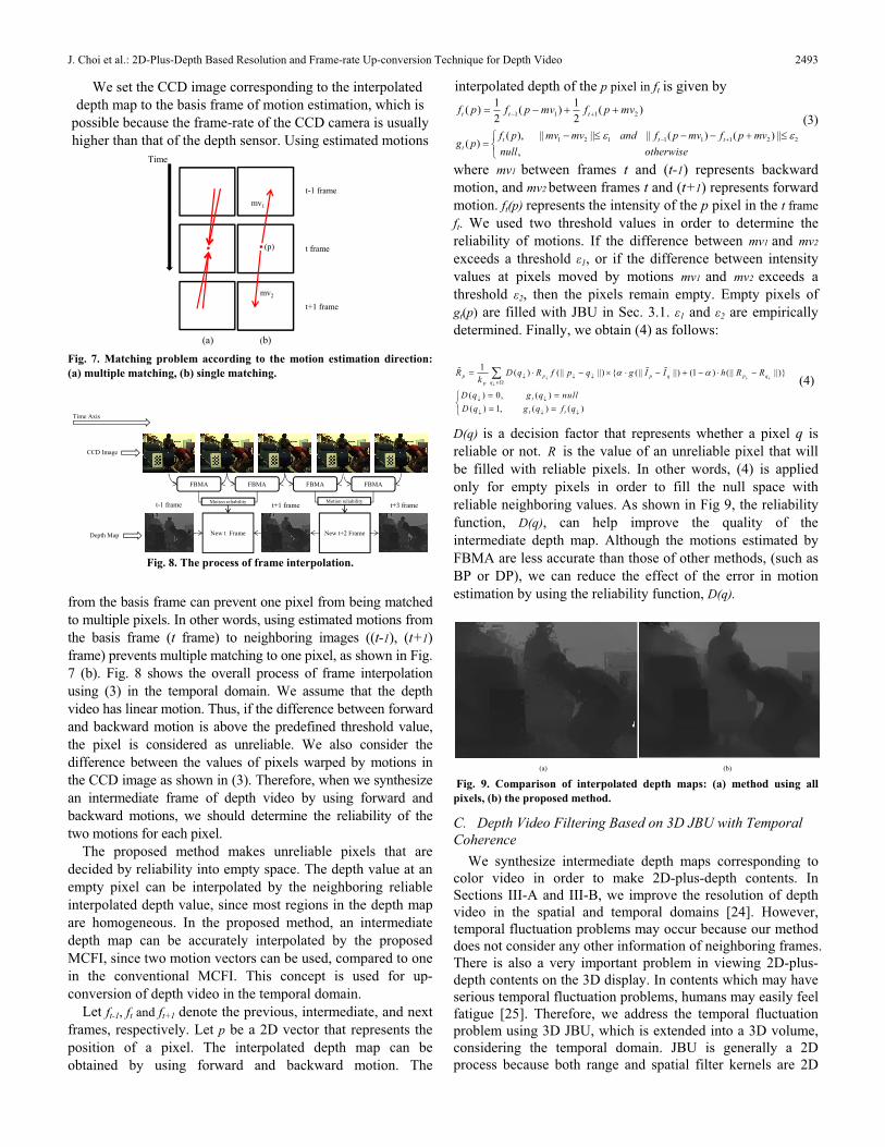
Fig. 7. Matching problem according to the motion estimation direction: (a) multiple matching, (b) single matching.
CCD Image
Depth Map
Time Axis
New t Frame New t+2 Frame
FBMA FBMA FBMA FBMA
t+1 framet-1 frame t+3 frameMotion reliability Motion reliability
Fig. 8. The process of frame interpolation.
from the basis frame can prevent one pixel from being matched to multiple pixels. In other words, using estimated motions from the basis frame (t frame) to neighboring images ((t-1), (t+1)frame) prevents multiple matching to one pixel, as shown in Fig. 7 (b). Fig. 8 shows the overall process of frame interpolation using (3) in the temporal domain. We assume that the depth video has linear motion. Thus, if the difference between forward and backward motion is above the predefined threshold value, the pixel is considered as unreliable. We also consider the difference between the values of pixels warped by motions in the CCD image as shown in (3). Therefore, when we synthesize an intermediate frame of depth video by using forward and backward motions, we should determine the reliability of the two motions for each pixel.
The proposed method makes unreliable pixels that are decided by reliability into empty space. The depth value at an empty pixel can be interpolated by the neighboring reliable interpolated depth value, since most regions in the depth map are homogeneous. In the proposed method, an intermediate depth map can be accurately interpolated by the proposed MCFI, since two motion vectors can be used, compared to one in the conventional MCFI. This concept is used for up-conversion of depth video in the temporal domain.
Let ft-1, ft and ft+1 denote the previous, intermediate, and next frames, respectively. Let p be a 2D vector that represents the position of a pixel. The interpolated depth map can be obtained by using forward and backward motion. The
interpolated depth of the p pixel in ft is given by
(3)
where mv1 between frames t and (t-1) represents backward motion, and mv2 between frames t and (t+1) represents forward motion. ft(p) represents the intensity of the p pixel in the t frameft. We used two threshold values in order to determine the reliability of motions. If the difference between mv1 and mv2
exceeds a threshold 1, or if the difference between intensity values at pixels moved by motions mv1 and mv2 exceeds a threshold 2, then the pixels remain empty. Empty pixels of gt(p) are filled with JBU in Sec. 3.1. 1 and 2 are empirically determined. Finally, we obtain (4) as follows:
(4)
D(q) is a decision factor that represents whether a pixel q is reliable or not. R is the value of an unreliable pixel that will be filled with reliable pixels. In other words, (4) is applied only for empty pixels in order to fill the null space with reliable neighboring values. As shown in Fig 9, the reliability function, D(q), can help improve the quality of the intermediate depth map. Although the motions estimated by FBMA are less accurate than those of other methods, (such as BP or DP), we can reduce the effect of the error in motion estimation by using the reliability function, D(q).
(a) (b)
Fig. 9. Comparison of interpolated depth maps: (a) method using all pixels, (b) the proposed method.
C. Depth Video Filtering Based on 3D JBU with Temporal Coherence
We synthesize intermediate depth maps corresponding to color video in order to make 2D-plus-depth contents. In Sections III-A and III-B, we improve the resolution of depth video in the spatial and temporal domains [24]. However, temporal fluctuation problems may occur because our method does not consider any other information of neighboring frames. There is also a very important problem in viewing 2D-plus-depth contents on the 3D display. In contents which may have serious temporal fluctuation problems, humans may easily feel fatigue [25]. Therefore, we address the temporal fluctuation problem using 3D JBU, which is extended into a 3D volume, considering the temporal domain. JBU is generally a 2D process because both range and spatial filter kernels are 2D
1 ( ) (|| ||) { (|| ||) (1 ) (|| ||)}
( ) 0, ( )( ) 1, ( ) ( )
p p p q p qqp
t
t t
R D q R f p q g I I h R Rk
D q g q nullD q g q f q
1 2 1 1 1 1 2 2( ), || || || ( ) ( ) ||( )
,t t t
t
f p mv mv and f p mv f p mvg p
null otherwise
J. Choi et al.: 2D-Plus-Depth Based Resolution and Frame-rate Up-conversion Technique for Depth Video 2493

, , , , , ,, ,,
1 (|| ||) { (|| ||) (1 ) (|| ||)}N NNp t p t p t q t p t q tt t
N qp t
R R f p q g I I h R Rk
structures. JBU is extended into a 3D volume by accumulating neighboring frames. As shown in Fig. 10, we use not only the CCD image and depth map for the interpolated frame, but also neighborhood frames to maintain temporal constancy in the final up-converted depth video. 3D memories, corresponding to the spatial filter kernel of depth images and the range filter kernel of CCD images, can be made by integrating neighborhood frames in the temporal domain as shown in Fig. 10. If the number of frames used in 3D JBU is 3, we use (t-1)and (t+1) frames in order to up-sample the resolution of the interpolated frame (t frame). The final up-sampled results are improved significantly from those of the conventional JBU, because both temporal and spatial information are considered. By using a 3-dimensional Gaussian filter as the spatial filter kernel and a 3D window as the range filter kernel, temporal fluctuation can be reduced, while the edge is preserved in the video. The 3D JBU equation is as follows:
(5)
In (5), t and tN represent the reference and neighborhood frames. The basic structure of 3D JBU is similar to that of the conventional JBU, except that filter kernels contain temporal neighborhood information. f indicates the 3-dimensional filter such as a Gaussian centered over ,tp in the frame t of a low-resolution image. g indicates the range filter kernel, centered at the pixel value at p in the frame t of a high-resolution image.
Fig. 10. Structure of 3D JBU (N=3).
In other words, it means the range filter kernel based on the difference in intensity values between corresponding pixels and neighborhood pixels in the 3D window of neighborhood frame, N. N represents the number of neighborhood frames used in 3D JBU. In this paper, we used 3-neighborhood frames (N=3) because of computational complexity. When depth video is finally up-sampled, the previous neighborhood images are needed, so that N-neighborhood frames per up-sampling process are needed in a memory. However, a system, such as that shown in Fig. 10, can be non-causal, since frame (t+1) is used in the final up-conversion process. It may cause delay at the up-conversion process. Therefore, we can solve this problem by using only previous frames. When the number of neighborhood frame N is 3, the first frame in the depth video can be up-sampled by using only corresponding frames,
since there is no previous frame. The subsequent frames can then be up-sampled by using a number of frames added by 1 until the Nth frame is input.
By extending 2D spatial information into 3D temporal information, we can obtain temporally consistent quality depth video. From the view-point of video coding, the reduction of temporal fluctuation can help save the bit rate. In the case of a 2D still image, the compression rate of an image in which most regions are homogeneous may be better than that of an image in which noise is randomly distributed. Similarly, temporal fluctuation problems may degrade the performance of video coding. Therefore, temporal fluctuation problems in the depth video should be removed in order to reduce both the bit rate in the coding and eye fatigue on the 3D display.
IV. EXPERIMENTAL RESULT
The proposed method was implemented with the Visual C++ 6.0 program except for the depth image acquisition which used MATLAB and tested on an Intel Core2 Quad 2.5 GHz processor and 2 GHz RAM. In the experiment, the Flea CCD camera developed by Point Grey Research, Inc. and the SwissRanger SR3000 depth sensor developed by MESA Imaging AG are used to acquire CCD images and depth images, as shown in Figs. 11 (a) and (b). The resolution of the Flea camera is 1024 768, and the frame-rate is 30 fps (frames per second). The resolution of the depth sensor is 176 144, and the frame-rate is about 15 fps. The two sensors are synchronized with each other in spite of the difference of frame-rate. As shown in Fig. 11 (c), in this experiment, two sensors have been placed near each other in parallel. The videos used in the experiment are “Two Men” (obtained by our fusion system, which consists of the SwissRanger SR3000 and Flea camera) and “Breakdancer” (provided by Microsoft Research).
(a) (b) (c)
Fig. 11. Experimental device and setup: (a) depth sensor, SwissRanger SR3000, (b) CCD camera, Flea , (c) experimental setup.
The 87th frame of “Breakdancer” is up-sampled according to the interpolation methods and up-conversion rates shown in Fig. 12. The up-conversion rate indicates how many times the up-converted image is an original. We can see that the PSNR of the proposed method is higher than the other algorithms, such as NN and Gaussian interpolation in all up-conversion rates, as shown in Fig. 12. However, it is difficult to apply the proposed method when the up-conversion rate is too high, such as 32, since the PSNR is too low to produce a satisfactory result. Fig. 13 shows the Intermediate View Rendering (IVR) results according to up-sampling methods using 1-view images,
2494 IEEE Transactions on Consumer Electronics, Vol. 56, No. 4, November 2010

differing from conventional IVR that uses 2-view images. Therefore, empty pixels are generated in occluded regions. The proposed method improves the quality of intermediate views at boundaries as shown in Fig. 13, and can be effectively applied to 3DTV systems based on 2D-plus-depth contents.
Fig. 12. Comparison of “Breakdancer” PSNR according to interpolation methods used in the resolution up-conversion.
The up-conversion result in the temporal domain is shown in Fig. 14. Motion vectors estimated from the CCD video using FBMA are used to interpolate an intermediate depth map (the 278th frame). The frame-rate of the depth sensor increases up to 30 fps. The “Breakdancer” sequences provided by Microsoft Research were also used in this experiment in order to measure PSNR, since it contains depth video. As the original image size gets smaller, that is, as the up-conversion rate is higher, the quality of the up-sampled image decreases, as shown in Fig. 15. When the up-conversion rate is 32, as in Fig. 15, the proposed method produces poor results because motion is estimated inaccurately in the very small down-sampled image. As the image size gets smaller, it is expected that the performance becomes poor because the motion vector is less accurate than the other algorithms. However, as shown in Fig. 15, we confirm that until the up-conversion rate is 8, the interpolated results maintain a level of quality similar to the other highly complex methods. Thus, we set the limit of the up-conversion rate to 8. In the experiment using the “Two men” video, we set the up-conversion rate to 4 in order to maintain satisfactory quality. An up-conversion rate of 4 is proper for “Two men,” since the original CCD image is quadruple the size of the depth map up-converted by the 1st JBU.
(a)
(b)
(c)
Fig. 13. Intermediate view results according to up-sampling methods (from left to right: view no. 0, 1, 2, 3): (a) proposed method, (b) NN interpolation, (c) Gaussian interpolation in “Breakdancer,” sequence.
(a)
(c)
277th frame 279th frame278th new frame
(b)
Fig. 14. Up-converted result in the temporal domain: (a) CCD images corresponding to the 277th, 278th, and 279th frames of “Two men,” (b) results of FBMA using the 277th, 278th, and, 279th CCD images, (c) interpolated depth map (278th) using FBMA results of (b) and 277th, 279th
depth maps.
Fig. 15. Comparison of “Breakdancer” PSNR according to motion estimation methods used in MCFI of the frame-rate up-conversion.
Temporal fluctuation problems may occur in the frame interpolated depth video using 2D JBU, since only one pair of images that consist of a CCD image and corresponding depth map are used without considering temporal coherence. Fig. 16 shows the results up-converted by 2D JBU and difference images between the frames. The background regions, which contain severe time fluctuation in the red box of Fig. 16, may cause eye fatigue in viewing 2D-plus-depth based 3D contents. Different depth values can be assigned in the regions having the same depth in the depth video because 2D JBU does not consider temporal coherence. In Fig. 17, 3D JBU (N=3) was used in the final up-sampling process in order to remove temporal fluctuation. We find that temporally consistent depth values were obtained in most parts, except for moving objects using 3D JBU, compared to Fig. 16. In addition, it improves the compression rate of depth video. By reducing the temporal fluctuation, we can obtain gain in video coding. As shown in Fig. 18, the compression rate of depth video using 3D JBU is higher than that using 2D JBU while PSNR is preserved to a degree of quality that people cannot distinguish between the original and compressed videos. The bit rate decreases in overall QP values, as shown in Fig. 18. Experimental results according to various QP values were obtained by using H.264 AVC JM 12.4.
J. Choi et al.: 2D-Plus-Depth Based Resolution and Frame-rate Up-conversion Technique for Depth Video 2495

(a)
(b)
Fig. 16. (a) Final depth video of “Two men” obtained by 2D JBU (from left to right: 277th, 278th, 279th) and (b) difference images (277th-278th,278th-279th)
V. CONCLUSION
In this paper, we propose a novel method that overcomes the physical limitations of TOF sensors. First, by using the proposed method, we improved the quality of low-resolution, low-frame-rate depth video while maintaining the spatial and temporal coherences. Second, the proposed method decreased the bit-rate and eye-fatigue for the depth video by removing the temporal fluctuation problems with 3D JBU. Therefore, we can obtain an efficient and comfortable depth video while PSNR is preserved to a degree of quality that people cannot distinguish between the original and compressed videos. It can be used to 2D-plus-depth 3DTV or many applications using TOF sensor.
(a)
(b)
Fig. 17. (a) Final depth video of “Two men” obtained by 3D JBU (from left to right: 277th, 278th, 279th) and (b) difference images (277th-278th, 278th-279th)
However, it is difficult to assess the quality of a result obtained by the proposed method, since there is no ground truth map. In the absence of a ground truth map, objective assessment is very difficult. For further research, 2D-plus-depth contents made by the proposed method will be used for subjective quality assessment on a 3D display. The 3D JBU process can also be a problem. A lot of time is consumed by using 3-dimensional memory. Therefore, the processing time will be reduced by a fast algorithm. In addition, we should address the problem of camera movement. Thus, 3D JBU should be extended to an algorithm that considers dynamic environments including change of scene and zoom parameter.
Bit
rate
(kbi
ts/s
)
QP value(a)
PSN
R
QP value(b)
Fig. 18. (a) Bit rate comparison of 3D JBU with 2D JBU, (b) PSNR comparison of 3D JBU with 2D JBU in “Two men” video.
REFERENCES
[1] S. Seitz, B. Curless, J. Diebel, D. Scharstein and R. Szeliski, “A Comparison and Evaluation of Multi-View Stereo Reconstruction Algorithms,” Proc. IEEE Conf. Comp. Vision and Pattern Recogn., vol. 1, pp. 519-528, 2006.
[2] M. Levoy, K. Pulli, B. Curless, S. Rusinkiewicz, D. Koller, L. Pereira, M. Ginzton, S. Anderson, J. Davis, J. Ginsberg, J. Shade and D. Fulk, “The digital Michelangelo project: 3D scanning of large statues,” Proc. ACM SIGGRAPH 2000, pp. 131-144, Jul. 2000.
[3] D. Scharstein and R. Szeliski. “A Taxonomy and Evaluation of Dense Two-Frame Stereo Correspondence Algorithms,” Int. J. Computer Vision., vol. 47, no. 1-3, pp. 7-42, Apr. 2002.
[4] S. A. Gudmundsson, H. Aanaes and R. Larsen, “Environmental Effects on Measurement Uncertainties of Time-of-Flight Cameras,” Int. Symp. Signals Circuits and Systems, pp. 1-4, Jul. 2007.
[5] J. Kopf, M. F. Cohen, D. Lischinski and M. Uyttendaele, “Joint bilateral upsampling,” ACM Trans. Graphics, vol. 26, no. 3, article. 96, Jul. 2007.
[6] S. Schuon, C. Theobalt, J. Davis and S. Thrun, “High-quality scanning using time-of-flight depth superresolution,” Proc. IEEE Conf. Comp. Vision and Pattern Recogn. Workshops, Jun. 2008.
[7] S. Borman and R. L. Stevenson, “Super-resolution from image sequences – a review,” Proc. Midwest Symp. Circuits and Systems, vol. 5, pp. 374-378, Apr. 1998.
[8] L. Wang, M. Liao, M. Gong, R. Yang and D. Nister, “High-Quality Real-Time Stereo Using Adaptive Cost Aggregation and Dynamic Programming,” Proc. Int. Symp. 3D Data Proc., Vis. and Transm., pp. 798-805, 2006.
[9] Q. Yang, R. Yang, J. Davis and D. Nister, “Spatial-depth super resolution for range images,” Proc. IEEE. Conf. Comp. Vision and Pattern Recogn., 2007.
[10] C. Tomasi and R. Manduchi, "Bilateral filtering for gray and color images," Proc. Int. Conf. Computer Vision, pp. 839-846, Jan. 1998.
[11] J. Zhu, L. Wang, R. Yang and J. Davis, “Fusion of Time-of-Flight Depth and Stereo for High Accuracy Depth Maps,” Proc. IEEE Conf. Comp. Vision and Pattern Recogn., 2008.
[12] J. Zhu, L. Wang, J. Gao and R. Yang, “Spatial-temporal fusion for high accuracy depth maps using dynamic MRFs,” IEEE Trans. Pattern Anal. Mach. Intell., vol. 32, no. 5, pp. 899-909, May. 2010.
[13] L. Alvarez, R. Deriche, J. Sanchez and J. Weickert, “Dense disparity map estimation respecting image discontinuities: A PDE and Scale-space
2496 IEEE Transactions on Consumer Electronics, Vol. 56, No. 4, November 2010

based approach,” J. of Visual Comm. and Image Rep., vol. 13, pp. 3-21, Mar. 2002.
[14] O. Faugeras and R. Keriven, “Variational principles, surface evolution, PDE’s, level set methods and the stereo problem,” IEEE Trans. Image Processing, vol. 7, no. 3, pp. 336-344, 1999.
[15] M. Gong, “Motion estimation using dynamic programming with selective path search,” Proc. Int. Conf. Pattern Recognition, vol. 4, pp. 203-206, 2004.
[16] J. Sun, NN. Zheng and HY. Shum, “Stereo Matching Using Belief Propagation,” IEEE Trans. Pattern Anal. Mach. Intell., vol. 25, no. 7, pp. 787-800, Jul. 2003.
[17] G. Bocciqnone, A. Marcelli, P. Napoletano and M. Ferraro, “Motion estimation via belief propagation,” Int. Conf. Image Analysis and Processing, pp. 55-60, Sep. 2007.
[18] O. Veksler, Y. Boykov and R. Zabih. “Fast approximate energy minimization via graph cuts,” IEEE Trans. Pattern Anal. Mach. Intell., vol. 23, no. 11, pp. 1222-1239, Nov. 2001.
[19] H. Kim and K. Sohn, “Hierarchical disparity estimation with energy based regularization,” Proc. Int. Conf. Image Processing, pp. 373-376, Sep. 2003.
[20] A. Huang and TQ. Nguyen, “A multistage motion vector processing method for motion-compensated frame interpolation,” IEEE Trans. Image Processing, vol. 17, no. 5, pp. 694-708, May. 2008.
[21] M. T. Orchard and G. J. Sullivan, “Overlapped block motion compensation: An estimation-theoretic approach,” IEEE Trans. Image Processing, vol. 3, no. 5, pp. 693-699, Sep. 1994.
[22] B. Choi, J. Han, C. Kim and S. Ko, “Motion-Compensated Frame Interpolation Using Bilateral Motion Estimation and Adaptive Overlapped Block Motion Compensation,” IEEE Trans. Circuits Syst. Video Technol., vol. 17, no. 4, pp. 407-416, Apr. 2007.
[23] D. Chan, H. Buisman, C. Theobalt and S. Thrun, “A Noise-Aware Filter for Real-Time Depth Upsampling,” Proc. ECCV Workshop on Multi-camera and Multi-modal Sensor Fusion Algorithms and Applications,2008.
[24] J. Choi, D. Min, B. Ham and K. Sohn, “Spatial and temporal up-conversion technique for depth video,” Proc. Int. Conf. Image Processing, pp. 3525-3528, Nov. 2009.
[25] Y. Nojiri, H. Yamanoue, A. Hanazato, M. Emoto and F. Okano, “Visual comfort/discomfort and visual fatigue caused by stereoscopic HDTV viewing,” Proc. SPIE Stereoscopic Displays and Virtual Reality Systems, vol. 5291, pp. 303-313, 2004.
BIOGRAPHIES
Jinwook Choi (S’09) received the B.S. degree in electrical and electronic engineering from Yonsei University, Seoul, Korea, in 2008. He is currently pursuing the Ph.D degree at Yonsei University. His research interests include stereo vision, 3-D modeling, view synthesis, super-resolution and HDR imaging.
Dongbo Min received the B.S., M.S. and Ph.D. degrees in electrical and electronic engineering from Yonsei University, Seoul, Korea, in 2003, 2005 and 2009, respectively. He then worked at Mitsubishi Electric Research Laboratories (MERL) as a post-doctoral researcher from Jun. 2009 to Jun. 2010. He is now working at Advanced Digital Sciences Center (ADSC), which was jointly founded by University of Illinois at
Urbana-Champaign (UIUC) and the Agency for Science, Technology and Research (A*STAR), a Singapore government agency, from July 2010. His research interests include 3D computer vision, video processing, 3D modeling and hybrid sensor system.
Kwanghoon Sohn (M’92) received the BE degree in electronics engineering from Yonsei University, Seoul, Korea, in 1983, the MSEE degree in electrical engineering from University of Minnesota in 1985, and the PhD degree in electrical and computer engineering from North Carolina State University in 1992. He was employed as a senior member of the research staff in the Satellite Communication Division at Electronics and Telecommunications Research Institute, Daejeon, Korea, from 1992 to 1993. Also, he was employed as a
postdoctoral fellow at the MRI Center in the Medical School of Georgetown University. He was a visiting professor of Nanyang Technological University from 2002 to 2003. He is currently a professor in the School of Electrical and Electronic Engineering at Yonsei University. His research interests include three-dimensional image processing, computer vision and image communication. Dr. Sohn is a member of IEEE and SPIE.
J. Choi et al.: 2D-Plus-Depth Based Resolution and Frame-rate Up-conversion Technique for Depth Video 2497