j1550w p. 1-16 - web design, print design, flash design...
TRANSCRIPT

OW
NE
R’S
MAN
UAL
TRADESMAN®
6-1/8” BENCH JOINTER
Model # J1550W Item #52573
CAUTION – FOR YOUR OWN SAFETY
READ YOUR OWNER’S MANUAL THROUGH COMPLETELY AND CAREFULLY BEFORE ATTEMPTING TO SET-UP OR OPERATE YOUR NEW POWER TOOL.
ALL OPERATORS OF THIS EQUIPMENT SHOULD READ AND UNDERSTAND ALL SAFETY RULES PRINTED ON THE MACHINE AND THIS OWNERS MANUAL BEFORE USE.
Your new Power Tool is a well built, carefully inspected versatile machine, capable of giving you many years of dependable service. Your power tool comes complete in one carton with a minimum of first assembly and setup required by you. When unpacking, be sure to check all packages and packing material for loose parts before discarding.
NOTICE: On the nameplate of your machine you will find the serial number and MFG date code of your unit. Please record these numbers on this manual cover for future service reference.
SERIAL # MFG. DATE # PURCHASE DATE: _____
POWER TOOL SPECIALISTS, INC E.WINDSOR,CT 06088 PRINTED IN TAIWAN
www.tradesman-rexon.com
1-800-243-5114

TABLE OF CONTENTS
PRODUCT SPECIFICATIONS
MOTOR CUTTING CAPACITY…………. 6-1/8” POWER SOURCE…………... DOUBLE INSULATED ….….
120 V AC, 60HZ, 10 AmpYes
CUTTING DEPTH CAPACITY FENCE TILT……….…………..
1/8” 90° & 45°(in and out)
HORSEPOWER……………... 1.5HP (Max. Developed) WEIGHT ………………………... 55 lb BLADE LENGTH................... 6-1/8” CUTTERHEAD DIAMETER 1-7/8” CUTTERHEAD SPEED……... 10000RPM CUTS PER MINUTE ………... 20000 NUMBER OF KNIVES……… 2
WARRANTY
Refer to the Warranty Card included for your power tool warranty information.
WARNING
POWER TOOL SAFETY
SECTION PAGE SECTION PAGE Product Specifications ……………………. 2 Know Your Jointer ………..…...….……... 8 Power Tool Safety ..………………………. 3 Assembly …………………………………. 9 Jointer Safety………………….…………... 4 Adjustments……………………..………... 10 Electrical Requirements and Safety……….. 5 Operation…………………………………. 12 Accessories and Attachments…………...… 6 Maintenance ……………………………… 15 Tools Needed For Assembly..…………….. 6 Troubleshooting Guide.…………………... 16 Carton Contents ………………………….. 7
2
Some dust created by power sanding, sawing, grinding, drilling and other construction activities contains chemicals (known tothe State of California) to cause cancer, birth defects or other reproductive harm. Some examples of these chemicals are: • Lead based paints • Crystalline silica from bricks, cement and other masonry products • Arsenic and chromium from chemically treated lumber Your risk from these exposures varies, depending on how often you do this type of work. To reduce your exposure to these chemicals: work in a well ventilated area and work with approved safety equipment such as those dust masks that are specially designed to filter out microscopic particles.

CAUTION! Before using your Jointer, it is critical that you read and understand these safety rules. Failure to follow these rules could result in serious injury or damage to the router table.
1. READ and become familiar with this entire Operator’s
Manual. LEARN the tool’s applications, limitations and possible hazards.
2. CAUTION! Look for this symbol that identifies important
safety precautions. It means CAUTION! BECOME ALERT! YOUR SAFETY IS INVOLVED!
3. NEVER OPERATE THIS MACHINE WITHOUT THE SAFETY GUARD IN PLACE.
4. DO NOT USE IN A DANGEROUS ENVIRONMENT
such as damp or wet locations or exposure to rain. Keep work area well lighted.
5. DO NOT use power tools in the presence of flammable liquids or gases.
6. KEEP WORK AREA CLEAN. Cluttered areas and benches invite accidents.
7. KEEP CHILDREN AWAY. All visitors should be kept at a safe distance from the work area.
8. DO NOT FORCE THE TOOL. It will do the job better and safer at the rate for which it was designed.
9. USE THE RIGHT TOOL. Don’t force the tool or attachment to do a job for which it is not designed.
10. WEAR PROPER APPAREL DO NOT wear loose clothing, gloves, neckties, rings, bracelets or other jewelry that may get caught in moving parts. Non-slip footwear is recommended. Wear protective hair covering to contain long hair.
11. WEAR A FACE MASK OR DUST MASK. Jointing / Planning operations produce dust.
12. DISCONNECT TOOLS before servicing and when changing accessories such as blades, cutters, etc.
13. REDUCE THE RISK OF UNINTENTIONAL STARTING. Make sure the switch is in the OFF position before plugging into the power supply.
14. USE ONLY RECOMMENDED ACCESSORIES. Consult the Operator’s Manual for recommended accessories. The use of improper accessories may cause injury to you or damage to the tool.
15. REMOVE ADJUSTING KEYS AND WRENCHES.
Form the habit of checking to see that keys and adjusting wrenches are removed from the tool before turning ON.
16. NEVER LEAVE TOOL RUNNING UNATTENDED. TURN THE POWER “OFF”. Do not leave the tool before it comes to a complete stop.
17. NEVER STAND ON TOOL. Serious injury could occur
if the tool is tipped or if the cutting tool is unintentionally
contacted.
18. DO NOT OVERREACH. Keep proper footing and balance at all times.
19. MAINTAIN TOOLS WITH CARE. Keep tools sharp and clean for most efficient and safest performance. Follow instructions for lubricating and changing accessories.
20. CHECK FOR DAMAGED OR LOOSE PARTS. Before further use of the tool, a guard or other part that is damaged should be carefully checked to ensure it will operate properly and perform its intended function. Check for alignment of moving parts, loose binding of moving parts, mounting and any other conditions that may affect its safe operation. A guard or other part that is loose or damaged should be properly adjusted repaired or replaced.
21. MAKE WORKSHOP CHILD PROOF with padlocks, master switches or by removing starter keys.
22. DO NOT operate the tool if you are under the influence of any drugs, alcohol or medication that could impair your ability to use the tool safely.
23. USE DUST COLLECTION SYSTEM whenever possible. Dust generated from certain materials can be hazardous to your health and in some cases, a fire hazard. Always operate the power tool in a well-ventilated area with adequate dust removal.
24. ALWAYS WEAR EYE PROTECTION. Any power tool can throw foreign objects into your eyes that could cause permanent eye damage. ALWAYS wear safety goggles (not glasses) that comply with ANSI safety standard Z87.1. Everyday glasses have only impact resistant lenses. They ARE NOT safety glasses. NOTE: Glasses or goggles not in compliance with ANSI Z87.1 could cause serious injury when they break.
25. DIRECTION OF FEED. Feed work into a blade or cutter against the direction of rotation of the blade or cutter only.
3

JOINTER SAFETY 1. Know general power tool safety. Make sure all
precautions are understood. 2. Whenever adjusting or replacing any parts on
jointer/planer, turn switch off and remove plug from power source.
3. Make sure all moving parts are free from interference. 4. Always wear eye protection of face shield. 5. Make sure blades are aligned and properly attached to
cutter head. Check blades periodically to assure they are secure.
6. After running switch on, allow jointer/planer to come to
full speed before operation. 7. Keep hands clean of all moving parts. 8. Do not force cut. Slowing or stalling will overheat motor. 9. Use quality lumber. Blades last longer and cuts are
smoother with good quality wood. 10. Never perform jointing, planning, or rabbeting cuts on
pieces shorter than 8 inches in length. 11. Never make jointing, planning, or rabbeting cut deeper
than 3/8 inch. 12. Always keep cutter head and drive guards and blade
guards in place and in proper operating condition. Do not remove guard for rabbeting operations.
13. Maintain the proper relationships of infeed and outfeed
table surfaces and cutter head blade path. 14. Do not back the work toward the infeed table. 15. Support the workpiece adequately at all times during
operation; maintain control of the workpiece.
16. Always use hold-down/ push blocks. 17. Take precautions against kickback. Do not permit
anyone to stand or cross in line of cutter head’s rotation. 18. Turn switch off and disconnect power whenever jointer /
planer is not in use. 19. Replace or sharpen blades as they become damaged or
dull. 20. Do not attempt to perform an abnormal or little used
operation without study and the use of adequate hold down/push blocks, jigs, fixtures, tops and like.
21. Check old lumber to be sure it’s free of nails, etc. 22. Keep jointer/planer maintained. Follow maintenance
instructions.
ELECTRICAL REQUIREMENTS CAUTION! POWER SUPPLY AND MOTOR SPECIFICATIONS The AC motor used in this jointer is a universal, nonreversible type. See “MOTOR” in the “PRODUCT SPECIFICATIONS” section on page 2. To avoid electrical hazards, fire hazards, or damage to the tool, use proper circuit protection. Your jointer is wired at the factory for 120V operation. Connect to a 120V, 15 Amp circuit and use a 15 amp. time delay fuse or circuit breaker. To avoid shock or fire, if power cord is worn or cut, or damaged in any way, have it replaced immediately.
4

ELECTRICAL REQUIREMENTS AND SAFETY
DOUBLE INSULATED The power tool is double insulated to provide a double thickness of insulation between you and tool’s electrical system. All exposed metal parts are isolated from the internal metal motor components with protecting insulation. Replacement parts – When servicing use only identical replacement parts. Polarized plugs – This tool has a plug that looks like the one shown below:
To reduce the risk of electrical shock, this tool has a polarized plug (one blade is wider than the other). This plug will fit in a polarized outlet only one way. If the plug does not fit fully in the outlet, reverse the plug. If it still does not fit, contact a qualified electrician to install the proper outlet. Do not change the plug in any way. CAUTION! Double insulation does not take the place of normal safety precautions when operating this tool. To avoid electrocution: 1. Use only identical replacement parts when servicing a tool with double insulation. Servicing should be performed by a qualified technician. 2. Do not use power tools in wet or damp locations or expose them to rain or snow. MOTOR SAFETY PROTECTION IMPORTANT: To avoid motor damage, the motor should be blown out or vacuumed frequently to keep woodchips from interfering with the motor ventilation. 1. CONNECT this tool to a 120V, 15 amp. circuit with a 15
amp. time delay fuse or circuit breaker. Using the wrong size fuse can damage the motor.
2. If the motor won’t start, UNPLUG THE TOOL. Check the cutter head to make sure it turns freely. If it is free, try to start the machine again. If the motor still does not start, refer to the “TROUBLESHOOTING GUIDE”
3. FUSES may “blow” or circuit breakers may trip frequently if: a)MOTOR is overloaded – overloading can occur if you
feed too rapidly or make too many start/stops in a short time.
b)LINE VOLTAGE is more than 10% above or below
the nameplate voltage rating. For heavy loads, the voltage at motor terminals must equal the voltage specified on the nameplate.
c)DULL jointer knives are used. 4. Most motor troubles may be traced to loose or incorrect
connections, overload, low voltage or inadequate power supply wiring. Always check the connections, the load and supply circuit if the motor doesn’t run well. Check minimum gauge for the length of extension cord you are using on the chart below.
GUIDELINES FOR EXTENSION CORDS Use a proper extension cord. Make sure your extension cord is in good condition. When using an extension cord, be sure to use one heavy enough to carry the current your product will draw. An undersized cord will cause a drop in line voltage, resulting in loss of power and cause overheating. The table below shows the correct size to use depending on cord length and nameplate ampere rating. If in doubt, use the next heavier gauge. The smaller the gauge number, the heavier the cord. Be sure your extension cord is properly wired and in good condition. Always replace a damaged extension cord or have it repaired by a qualified person before using it. Protect your extension cords from sharp objects, excessive heat and damp or wet areas. Use a separate electrical circuit for your tools. This circuit must not be less than # 12 wire and should be protected with a 15 Amp time delay fuse. Before connecting the tool to the power line, make sure the switch is in the OFF position and the electric current is rated the same as the current stamped on the motor nameplate, running at a lower voltage will damage the motor. MINIMUM GAUGE FOR EXTENSION CORDS (AWG)
(When using 120 volts only) Ampere Rating Total length of cord in feet more than not more than 25’ 50’ 100’ 150’ 0 6 18 16 16 14 6 10 18 16 14 12 10 12 16 16 14 12 12 16 14 12 not recommended
CAUTION: In all cases make certain the receptacle in question is properly grounded. If you are not sure have a certified electrician, check the receptacle.
5

PRE ASSEMBLY
ACCESSORIES AND ATTACHMENTS Use only the recommended accessories with this jointer.
TOOLS REQUIRED FOR ASSEMBLY
CARTON CONTENTS UNPACKING AND CHECKING CONTENTS Separate all parts from packing material. Check each one with the illustration and the list of carton contents (see Pages 6 & 7). Make certain you have all required parts before discarding any packing material. CAUTION! To avoid the risk of personal injury: • If any parts are missing, do not attempt to assemble
the jointer, plug in the power cord or turn the switch ON until the missing parts are obtained and correctly installed.
TABLE OF LOOSE PARTS
ITEM DESCRIPTION QUANTITYA Jointer 1 B Fence bracket assembly 1 C T - wrench 1 D Fence 1 E Bolts 4 F Push block 2 G Pan head screw 2 H Extension wing 1 I Screws 2 J Nuts 2 K Allen wrench 1
Phillips Screwdriver
6

CARTON CONTENTS
A
B
C
D E
F
G
H
I
J
7
K
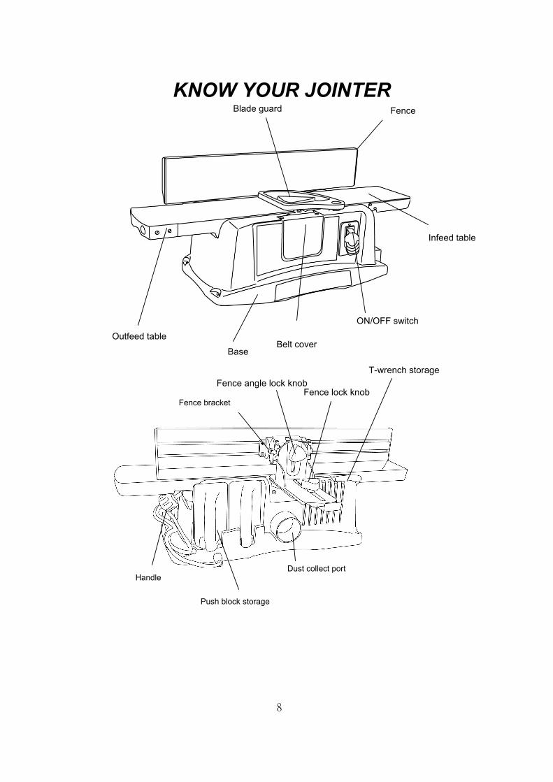
KNOW YOUR JOINTER
Blade guard
Fence angle lock knob
Dust collect port
Belt cover Outfeed table
Handle
Base
ON/OFF switch
Push block storage
Infeed table
Fence lock knobFence bracket
T-wrench storage
8
Fence

ASSEMBLYEstimated Assembly Time 20~40 minutes CAUTION! Never connect the plug to the power source outlet until all installations and adjustments are completed and you have read and understood the safety and operational instructions. Assembling the Fence (Fig. 1) 1. Assemble the fence (1) and fence bracket (2) with four bolts (3)
and tighten all bolts. NOTE: The curve of fence has to face downward. Fig. 1 Installing the Fence Assembly (Fig. 2) 1. Attach the fence assembly to the back of the tool body, as
shown (Fig.2), with two pan head screws (1) and tighten. Fig. 2 Installing the Extension Wing (Fig. 3) 1. Thread the nuts (1) into the bolts (2). 2. Place the rods into the holes (3) provided in the table. 3. Insert the bolts (2) into table hole and tighten to hold the
extension rod. Fig. 3
Removing or Installing the Blade CAUTION! To avoid injury from an accidental start, make sure the switch is in the OFF position and plug is not connected to the power source outlet. 1. Unplug the tool from the outlet. 2. Turn the cutter head until you expose four socket head bolts. 3. Remove the four bolts (1) with the Allen wrench 4. Carefully remove the hold down plate by lifting straight. 5. Carefully remove the blade by lifting both ends straight up. Fig. 4 Fig. 5 6. The blade (2) is designed with two cutting edges. If using the other side of the blade or replacing the blade, place the blade on the cutter head (3) by locating the two slotted holes in the blade over the locating pin on the cutter head. (Fig. 5) 7. Adjust the blade position so that it is positioned uniformly in the center of cutter head. 8. Replace the hold down with the two locating pins. 9. Replace the four Allen head bolts with the Allen wrench. Do not tighten. Check blade height at both ends of blade. (See Adjust Blade Height) 10. Tighten all bolts.
1
2
3
1
2
3
1
2
1
1
2
3
9

ADJUSTMENTSCAUTION! To avoid injury from an accidental start, make sure the switch is in the off position and the plug is not connected to the power source outlet. Note: This tool is accurately adjusted before shipping from the factory. Check the following accuracy and readjust them if necessary in order to obtain the best results in operation. CAUTION! THE KNIVES ARE SHARP. DISCONNECT THE MACHINE FROM THE POWER SOURCE BEFORE ADJUSTING. Adjusting Knives (Fig. 6, 6-1) 1. Remove cutter head guard. 2. Rotate cutter head and loosen four screws (1 – Fig. 6). NOTE:
Do not overly loosen the screws. Loosen one half turn or only enough so knife can slide between locking plate and cutter head.
3. Place a straight edge (2 – Fig. 6-1) on the outfeed table extending out over the knife as shown. Turn cutter head slowly and check that blade lightly touches straightedge without lifting it on both ends. CAUTION! The cutter head blades are extremely sharp, use a piece of wood and do not let your fingers contact the cutting edge.
4. If adjustment is required, using wrench (3), turn screw (4) until knife just touches straight edge. Adjust knife at near end of cutter head in the same manner turning screw. Tighten four screws (1) on each cutter head after adjustment is made.
5. Adjust remaining knife in the same manner. Fig. 6
Fig. 6-1
Adjusting Table Alignment (Fig. 7) 1. Place a straight edge on the outfeed table extending
over the infeed table. 2. If the outfeed table is not parallel with infeed table, adjust the
knob (4) counterclockwise to raise the infeed table level with the outfeed table.
3. If the tables are not level, loosen the screw (1), then adjust the infeed table level with the Outfeed table. Finish by turning the screw (1) until it touches the frame of the table then secure in position with the jam nut (5).
Fig. 7 Adjusting The Depth Scale (Fig. 7) 1. Once the outfeed table is parallel with the infeed table, adjust the depth scale (2) to the 0 mark by the screw (3).
Adjusting The Fence And Fence Scale (Fig. 8) 1. Place a combination square on the table and against the fence. 2. If the table and fence is not 90° to the table, loosen the adjust
knob (1) and square the fence lock knob (1). 3. Adjust the fence scale (2) to the 0 mark by loosing the screw
(3), adjusting the pointer to 0 then retightening the screw. Fig. 8
1 3
4
1
2
3
1 3 2
4
10
5

ADJUSTMENTSAdjusting Blade Guard (Fig. 9) CAUTION! Do not lubricate the pivot point of the blade guard. Oil and lubrication products may contain chemicals that can damage and/or destroy blade guard or other plastic parts. The blade guard needs adjustment or spring replacement if it does not cover the cutter head when released. To adjust or replace spring: 1. Lay the Jointer / Planer on the side so that the switch is facing
upwards. 2. Loosen and remove screw and wave washer on the base that
secure the blade guard. 3. Slide out blade guard. 4. If the spring has lost its’ tension, it must be replaced. Slide out
spring from the dimple. Contact technical support for replacement.
5. Replace new spring so the short arm of the spring is inside the whole on the body.
6. Position the blade guard so that the long arm of the spring is against the wall of the blade guard.
7. Secure the blade guard using pan head screw and washer. 8. Make sure the blade guard functions appropriately. Fig. 9 Mounting The Jointer (Fig. 10)
CAUTION! We highly recommend that you bolt this jointer securely to a workbench to gain maximum stability. 1. Locate and mark the four bolt holes on the bench. (Fig. 10) 2. Drill these four holes with a 3/8” drill bit. 3. Bolt the jointer/ planner on to the bench with bolts supplied.
Fig. 10
Extension Support Roller Height Adjustment The extension support rollers must be level with the outfeed table. To adjust: 1. Remove the rear locking screw (1) located on the back side
of the inside support roller (2). 2. Loosen but do not remove the front locking screw (3) located
on the front side of the inner support roller (2). 3. 3Place a straight edge (4) or ruler on top of the outfeed table
(5) and inside support roller (2). ( Fig. 13) 4. Place a flathead screwdriver into the slot on the rear
mounting hole of the roller cylinder (2) and turn left or right accordingly until the roller is level with the outfeed table (5).
5. When the roller is level with outfeed table, replace the
rear mounting screw and tighten both front and rear screws securely.
6. Place a straight edge or ruler on top of the outfeed table and both roller supports and repeat above steps for adjusting the outside roller.
11
Fig. 11
Fig. 12
3
2
1
2
2 5
4 Fig. 13

OPERATION CAUTION! Never connect the plug to the power source outlet until all installations and adjustments are completed and you have read and understood the safety and operational instructions. ON / OFF Switch Panel (Fig. 14) The “ON / OFF” switch has a removable, safety key. With the key removed from the switch, unauthorized and hazardous use by children and others is minimized. 1. To turn the jointer “ON”, insert the key (2) into the slot of the
switch (1), and move the switch upward to the “ON” position. 2. To turn the jointer “OFF”, move the switch downward. 3. To lock the switch in the “OFF” position, grasp the yellow key
of the toggle switch and pull it out. 4. With the switch key removed, the switch will not operate to
power the jointer on. 5. If the switch key is removed while the jointer is running, it can
be turned “OFF” but cannot be restarted without inserting the switch key.
6. Never leave the jointer unattended. Turn the power switch “OFF” and wait until it comes to a complete stop, and remove the safety key to prevent unauthorized starts.
CAUTION! ALWAYS lock the switch “OFF” when the jointer is not in use. Remove the key and keep it in a safe place, preventing unauthorized use. Fig. 14 Basic Jointer / Planer Operations Jointer / planer is used to surface the faces and edges of boards, produce a flat surface on warped boards and shape bevels, chamfers and tapers. The jointer / planner features cast aluminum infeed and outfeed tables, lightweight plastic body with smooth work surfaces and guide fence tilts 45°(inward) and 45°(outward). Jointer-Jointing is a surfacing operation in which a small amount of wood is removed from the edges and faces of boards to get smooth, straight and even surfaces such that the two edges that run across the planning blocks would fit together perfectly, forming a seamless joint. Planer-planning refers to the sizing of lumber to a desired thickness while creating a level surface parallel to the opposite size of the
board. Depth of cut is the term used to indicate how deep the blades will cut into the workpiece. CAUTION! 1. Operation of any power tool can result in foreign objects
being thrown into eyes, which can result in severe eye damage. Always wear safety glasses before commencing power tool operation.
2. For your own safety, read all of the instructions and safely precautions before operation tool.
Depth of Cut (Fig. 7) The depth of cut is adjusted by the relative positioning of the infeed table with respect to the cutter head. Infeed table can be raised or lowered using the handle (4). Turning the handle anticlockwise will lower the infeed table causing more wood to be removed from workpiece. Turning the handle clockwise will raise the infeed table causing less wood to be removed from workpiece. Do not make jointing or planning cuts deeper than 1/8”. Use The Fence (Fig. 15) The fence can be adjusted to cut various angles from 0°~ 45° inward and outward. The fence can be tilted inward up to 45° (toward the cutter head ) to maintain greater stability of a narrow workpiece or up to 45° outward (away from cutter head) for larger angle cutting operations. To adjust fence angles: 1. Loosen fence angle lock knob (1). 2. Adjust the fence to the desired angle position. 3. Tighten the fence angle lock knob (1). To adjust fence forward position: 1. Loosen fence lock knob (2). 2. Adjust the fence to the desired position. 3. Tighten the fence lock knob (2).
Fig. 15
1
2
2
1
12

OPERATION Blade guard The blade guard provides protection over the cutter head. It must always be in place and function properly. Check the guard to make sure it functions properly. To check: 1. Pass a ¼” thick piece of wood over the cutter head between the
guard and the fence. The guard will open and leave way for the wood to pass. The guard must return to the original position automatically when the wood passes through.
2. Open the blade guard all the way until it stops, and release it several times. It should always return to its original position.
CAUTION: If the blade guard fails to operate properly, the spring must be replaced or adjusted.
3. To replace spring, contact technical support. To adjust or to assemble spring, see “ Adjusting Blade Guard”.
Avoid Damage to Blades Jointer / Planer is a precision woodworking machine and should only be used on quality timber. Using bad timber could result in a poor quality cut on subsequent pieces. For proper operation, it is preferable to use the jointer with a dust collecting system attached to the exhaust port in the rear of the jointer. Attaching a dust collecting system is especially beneficial when taking deeper cuts to prevent clogging of wood chips. 1. Do not use dirty boards. Dirt and stones are abrasive and will
wear blades. 2. Remove nails and staples. 3. Avoid knots. Caution: When passing over knots, workpiece
can separate causing a dangerous condition. 4. Assess value of badly warped boards. Operator can be tempted
to use too deep of cut to square boards quickly. Use several passes to maintain a level surface.
Feeding Workpiece (Fig. 16, 17) Feed rate refers to rate at which wood is passed over blades. An even feed will produce a uniform service. To feed workpiece: 1. Hold the board firmly down on both tables and against the
fence. 2. Use push blocks. 3. Feed the board at a continuous even rate of speed. Any
hesitation or stopping could cause a “step” to be cut on the edge of the board.
4. As the trailing hand passes over the cutter head, remove the leading push-block.
5. Continue feeding while placing the leading block behind the trailing block until the entire length of the board is cut.
6. Feed with the grain whenever possible. 7. If the nature of the workpiece is such that it must be fed
against the grain, take very light cuts and feed slowly. 8. When using long workpieces, to avoid injury from slips or
kickbacks and to exert even pressure on the cutter head, use extra supports at both infeed and outfeed ends.
Fig. 16 Fig. 17 Using Push Blocks (Fig. 18) 1. Always use push-blocks when jointing. 2. Grasp the push-blocks flat on top of workpiece and push the
workpiece down against the table. 3. Use a hand-over-hand motion to maintain control over the
workpiece at all times. 4. When planning workpiece between 1/2” – 3/4” and narrower
than the push-blocks, tilt the push-blocks so that it clears the cutter head guard while feeding.
Fig. 18
13
With the grain
Against the grain
FEED
FEED

OPERATION Beveling And Chamfering (Fig. 19) 1. The fence on the jointer / planer is adjustable from 45 °inward
to 45° outward. Adjust the fence to the desired angle and tighten fence lock knobs.
2. Beveling refers to cutting the entire edge of a board at an angle. Beveling may require several passes due to the depth of cut needed.
3. Chamfering refers to removing only the corner of the edge of a board. Normally a chamfer is made on one pass; so a 1/8 inch depth of cut is maximal.
Fig. 19 Checking for Worn Blades Condition of blades will affect precision of cut. If blade wear is not observed when checking the blade height, the quality of cut will indicate the blade condition. Dull blades will tear rather than sever wood fiber. A raised grain will occur when dull blades pound on wood where there is difference in density. A raised ridge will be produced where the blades have been nicked.
Sharpening Blades (Fig. 20) The blades can be honed individually by whetting them with a fine sharpening stone. Make sure oilstone is flat and is not worn. To sharpen blades: 1. Partially cover the stone with paper to protect the table top. 2. Position infeed table so stone will contact blade along its
beveled surface. 3. Stroke the stone across blade from one side to other while
stone is also moved slightly in the direction of feed. 4. Make sure to do the same number of strokes on each place. 5. If the blades are nicked they must be replaced or reground.
They can be reground several times until they become 13/16” wide. Never install unbalanced blades or reground blades less than 13/16” wide.
NOTE: Many shops do not have capabilities to resurface blades. Yellow pages should list “ Sharpening Services” or “ Tool Grinding”. Fig. 20
Chamfer Edge
Bevel Edge
14

MAINTENANCE DANGER ! Never put lubricants on the blade while it is spinning. CAUTION! To avoid fire or toxic reaction, never use gasoline, naphtha, acetone, lacquer thinner or similar highly volatile solvents to clean the thickness planer. CAUTION! To avoid injury from unexpected starting or electrical shock, unplug the power cord before working on the tool. CAUTION! For your safety, this tool is double-insulated. To avoid electrical shock, fire or injury, use only parts identical to those identified in the parts list. Reassemble exactly as the original assembly to avoid electrical shock. REPLACING CARBON BRUSHES (Fig. 21) The carbon brushes furnished will last approximately 50 hours of running time, or 10,000 ON/OFF cycles. Replace both carbon brushes when either has less than 1/4” length of carbon remaining, or if the spring or wire is damaged or burned. To inspect or replace brushes, first unplug the tool. Then remove the black plastic cap (1) on the side of the motor (2). Remove the cap cautiously, because it is spring-loaded. Then pull out the brush and replace. Replace for the other side. To reassemble reverse the procedure. The ears on the metal end of the assembly go in the same hole the carbon part fits into. Tighten the cap snugly, but do not over tighten. NOTE: To reinstall the same brushes, first make sure the brushes go back in the way they came out. This will avoid a break-in period that reduces motor performance and increase wear. FIG. 21
Replacing Timing Belt (Fig. 22) 1. Turn the switch to “OFF” position and unplug the tool
from power source. 2. Loosen and remove the two bolts (1) and belt cover (2). 3. Loosen the timing belt adjustment bolt (3) but not remove it.
4. Remove old timing belt by “walking it off the pulleys”. You rotate the belt while pulling away from the pulleys to remove.
6. Replace with new timing belt in reverse manner as described in step 4.
7. Re-tighten the timing belt adjustment bolt (3) so there is approximately 3/8” to ½” full belt deflection when pressed on the center of the belt.
8. Secure belt adjustment bolt (3) into position by locking the jam nut on the bolt into position against the table.
6. Replace the belt cover (2) and with the two bolts (1) and tighten. NOTE: Make sure that the full width of belt is on both pulleys. Fig. 22 LUBRICATION Motor and cutter head bearings are sealed and need no
lubrication. Gears and elevation screws should be cleaned of debris and
greased. The tables can be coated with a lubricant such as furniture
wax, to make the workpiece feed smoother. Be sure the lubricant used does not affect the ability to finish the workpiece with varnish, sealer, etc. Do not use any silicone base lubricants.
CLEAN JOINTER Keep jointer clean of any wood chips, dust, dirt or debris.
2
1
1
2
15
Replacing timing belt
Removing timing belt
3

TROUBLESHOOTING TROUBLESHOOTING GUIDE
To avoid injury from accidental starting, always turn switch OFF and unplug the Jointer before moving, replacing the blade or making adjustments. Consult technical support if for any reason the motor will not run.
PROBLEM PROBLEM CAUSE REMEDY SUGGESTED Motor does not start 1. Defective switch
2. Defective motor 3. Low line voltage.
1. Have switch replaced. 2. Have motor replaced/repaired. NOTE: 1 and 2 must be done by a qualified service technician. Consult service center. 3. Correct low line voltage condition.
Motor stalls (resulting in blown fuses or tripped circuit breakers)
1. Circuit overloaded 2. Low line voltage 3. Motor overloaded 4. Incorrect fuses on circuit
breakers 5. Short circuit in motor; loose
connections or worn insulation on lead wires
1. Reduce circuit load ( turn off other appliances). 2. Correct low line voltage conditions. 3. Reduce load on motor. 4. Have correct fuses on circuit breakers installed. 5. Inspect terminals in motor for damaged insulation
and shorted wires and have them replaced.
Motor starts slowly or fails to come to full speed
1. Defective motor windings 2. Clogged wood chips
1. Have motor replaced/repaired. 2. Take shallow depth of cut and attach a shop-vac to
exhaust port. Motor running too hot
1. Motor overloaded 2. Restricted air circulation due
to dust accumulation
1. Reduce load on motor 2. Have correct fused or circuit breakers installed. 3. Reduce circuit load (turn off other appliances).
Frequent opening of fuses or circuit breakers
1. Motor overloaded 2. Fuses or circulation due to
dust accumulation
1.Reduce load on motor. 2. Clean dust and restore normal air circulation.
Snipe (gouging at end of boards)
1. Dull blades 2. Inadequate support of long
boards 3. Uneven feed
1. Replace or sharpen blades. See “Sharpening Blade”. 2. Support long boards. 3. Reduce circuit load (See “ Feeding workpiece.”)
Uneven depth of cut 1. Blade height not uniform 2. Fence not perpendicular to
jointer bed 3. Feeding wood too fast
1. Adjust blade height. See “ Adjusting Blade Height”. 2. See “ Positioning fence. 3. Feed wood slower.
45° cuts inaccurate 1. Fence indicator not adjusted properly
2. Fence bottom not even with outfeed table due to wood chips under fence
1. Adjust fence pointer at zero. 2. Clean wood chips from underside of fence.
Fuzzy grain 1. Planing wood with high moisture
1. Remove high moisture content from wood by drying
Torn grain 1. Too heavy a cut 2. Blade cutting against grain3. Dull blades
1. Reduce depth of cut. 2. Feed work along grain. 3. Replace or sharpen blades.
16

PART LIST
I.D. Description Size Qty I.D. Description Size Qty2460 CUTTER SHAFT GUARD #23 1 0TZV PULLEY 1 2461 TORSION SPRING 1 0TZW COMPRESSION SPRING 1 2462 POINTER 1 0TZX PRESSURE BAR 2 08VH CLAMP-CORD 1 0TZY BLADE 2 0HVV BALL BEARING 2 0U00 ADJUST BOLT 1 0J3L WRENCH HEX. 1 0U01 V-RIBBED BEIT(POIYOURETHANE) 1 0J4F FLAT WASHER φ8X16-2.5 1 0U05 SWITCH BOX #06 1 0J4U FLAT WASHER φ6*18-1.5 1 0U08 CUTTER SHAFT 1 0J4U FLAT WASHER φ6*18-1.5 1 0U09 CUTTER HEAD 1 0J4U FLAT WASHER φ6*18-1.5 2 0U0K PLATE COVER #06 1 0JB9 WAVE WASHER BWW-6201 1 0U0L FENCE 1 0JEA C-RING A-12 1 0U0M NUT 1 0JEV E-RING E-6 4 0U0N BLOCK #06 1 0JQH HEX. HD. BOLT M6*1.0-12 1 0U0P PLATE COVER #06 1 0JXA HEX. SOC. SET SCREW M6*1.0-12 3 0U0R ANGLE SEAT #06 1 0JXA HEX. SOC. SET SCREW M6*1.0-12 4 0U0S CLAMPER BRACKET #06 1 0JZ7 HEX. SOC. SET SCREW M6*1.0-30 1 0U0U ANGLE LABEL 1 0K14 HEX. HD. SCREW AND WASHER M6*1.0-16 2 0U0V HEIGHT REGULATER BRACKET #06 1 0K23 HEX.SOCKET HD.CAP SCREWS M6X1.0-16 10 20RL SHAFT-PIVOT 2 0K2A HEX.SOCKET HD.CAP SCREWS M6*1.0-25 4 20V1 PUSH -BLOCK 2 0K2B HEX.SOCKET HD.CAP SCREWS M6*1.0-16 2 20VF HEX. SOC. COUNTERSUNK HD. SCREW M4*0.7-10 4 0K6W CR.-RE. TRUSS HD. SCREW M3*0.5-6 2 22XH EXTENSSION SPRING 1 0K71 CR.-RE. TRUSS HD. SCREW M5*0.8-8 4 22YN PLATE 1 0K71 CR.-RE. TRUSS HD. SCREW M5*0.8-8 1 24U2 KNOB #23 1 0K7F CR. RE. ROUND WASHER HD. SCREW M5*0.8-8 1 24U3 NEEDLE POINTER 1 0K7K CR. RE. ROUND WASHER HD. SCREW M6*1.0-12 4 24U5 KNOB #23 1 0K8E CR. RE.COUNT HD. TAPPING SCREW M5*16-12 2 24U7 KNOB #23 1 0KA4 CR.RE. PAN HD. TAPPING SCREW M4*16-16 2 24UQ SWITCH MTG PLATE 1 0KA4 CR.RE. PAN HD. TAPPING SCREW M4*16-16 2 24VW HANDLE #23 1 0KDY CR. RE. PAN HD. SCREW M6*1.0-30 1 24VY MOTOR ASS'Y #06 1 0KMS HEX. NUT M6*1.0 T=5 1 24WF TABLE 1 0KMS HEX. NUT M6*1.0 T=5 1 26KD COLLAR 1 0KMT HEX. NUT M8*1.25 T=5 1 26LG POWER CABLE 1 0KQM SQUARE NUT M6*1.0 T=5 4 28AD SPECIAL BOLT 8 0KQX NUT CHUCK M6*1.0 T=6 1 28J5 BODY #23 1 0KQX NUT CHUCK M6*1.0 T=6 1 28J6 CVARD-BELT #23 1 0KT5 GUARD-CORD 1 28J7 SCALE 1 0KTH STRAIN RELIEF 2 28NM ROCKER SWITCH 1 0TZK FOOT PAD 4 292G TRADE-MARK LABEL 1 0TZL INFEED TABLE SUPPORT 1 292H LABEL 1 0TZN INFEED TABLE #AW 1 292J CAUTION LABEL 1 0TZQ RETAINING CLIP ASS'Y 4 292K WARNING LABEL 1 0TZR PLATE CLAMP 1
17

18
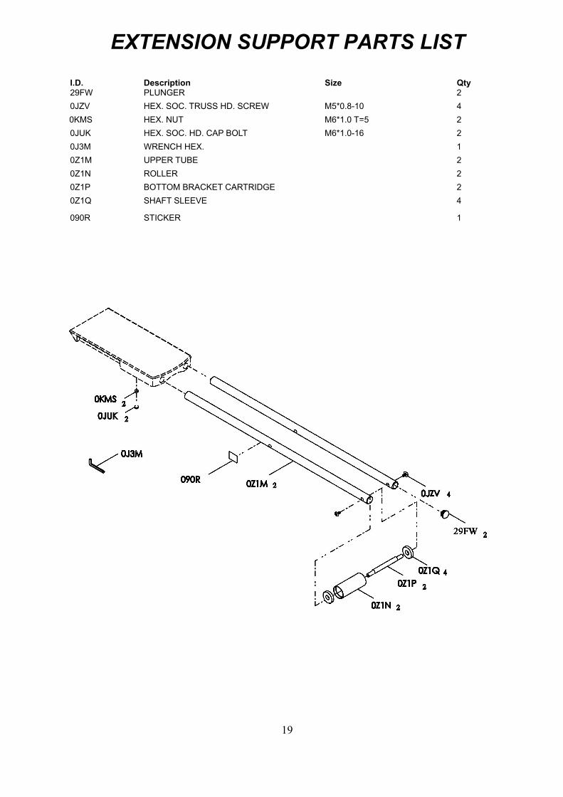
EXTENSION SUPPORT PARTS LIST
I.D. Description Size Qty 29FW PLUNGER 2 0JZV HEX. SOC. TRUSS HD. SCREW M5*0.8-10 4 0KMS HEX. NUT M6*1.0 T=5 2 0JUK HEX. SOC. HD. CAP BOLT M6*1.0-16 2 0J3M WRENCH HEX. 1 0Z1M UPPER TUBE 2 0Z1N ROLLER 2 0Z1P BOTTOM BRACKET CARTRIDGE 2 0Z1Q SHAFT SLEEVE 4
090R STICKER 1
19

I.D. Description Size Qty 0J70 FLAT WASHER 1/4*3/4-7/64 1 0JB8 WAVE WASHER BWW-6200 1 0JPD HEX. HD. BOLT M6*1.0-16 1 0JPD HEX. HD. BOLT M6*1.0-16 1 0JX3 HEX. SOC. SET SCREW M5*0.8-8 2 0KAD CR.RE. PAN HD. TAPPING SCREW M4X0.7-8 3 0KCL CR.RE. PAN HEAD TAPPING & WASHER SCREW M5*16-12 4 0KCR CR.RE. PAN HEAD TAPPING & WASHER SCREW M5*12-60 2 0QQS BRUSH HOLDER ASS'Y 2 0QQT BRUSH ASS'Y 2 0QR0 BRUSH COVER 2 0QR1 RUBBER PIN 1 0QR1 RUBBER PIN 1 147L CR.RE. PAN HEAD TAPPING & WASHER SCREW M5*16-30 4 149S FRONT END BELL #06 1 149T MOTOR BRACKET 1 149U MOTOR PULLEY 1 245H MOTOR COVER #06 1 24LH FLOW GUIDE 1 24UC FIELD ASS'Y 1 24UE ARMATURE ASS'Y 1
MOTOR PARTS LIST MOTOR PARTS LIST
19
20