jaa, jaf and jag pneumatic indicating controllers · 2019-01-02 · jaa, jaf and jag pneumatic in...
TRANSCRIPT
— ABB meAsurement & AnAlytics | dAtA sheet
JAA, JAF and JAGPneumatic indicating controllers
2 JA A, JAF And JAG PNEUMATIC INdICATINg CoNTrollErs | ds/JAx_dBT_dTE-EN rev. H
—Measurement made easyEngineered solutions for all applications
—Campo series reliable pneumatic instrumentation
—High reliability with good dynamic response
—Reduced maintenance and easily removable components
—Low air consumption
—
High compatibility with pneumatic valves
3JA A, JAF And JAG PNEUMATIC INdICATINg CoNTrollErs | ds/JAx_dBT_dTE-EN rev. H
—Introduction
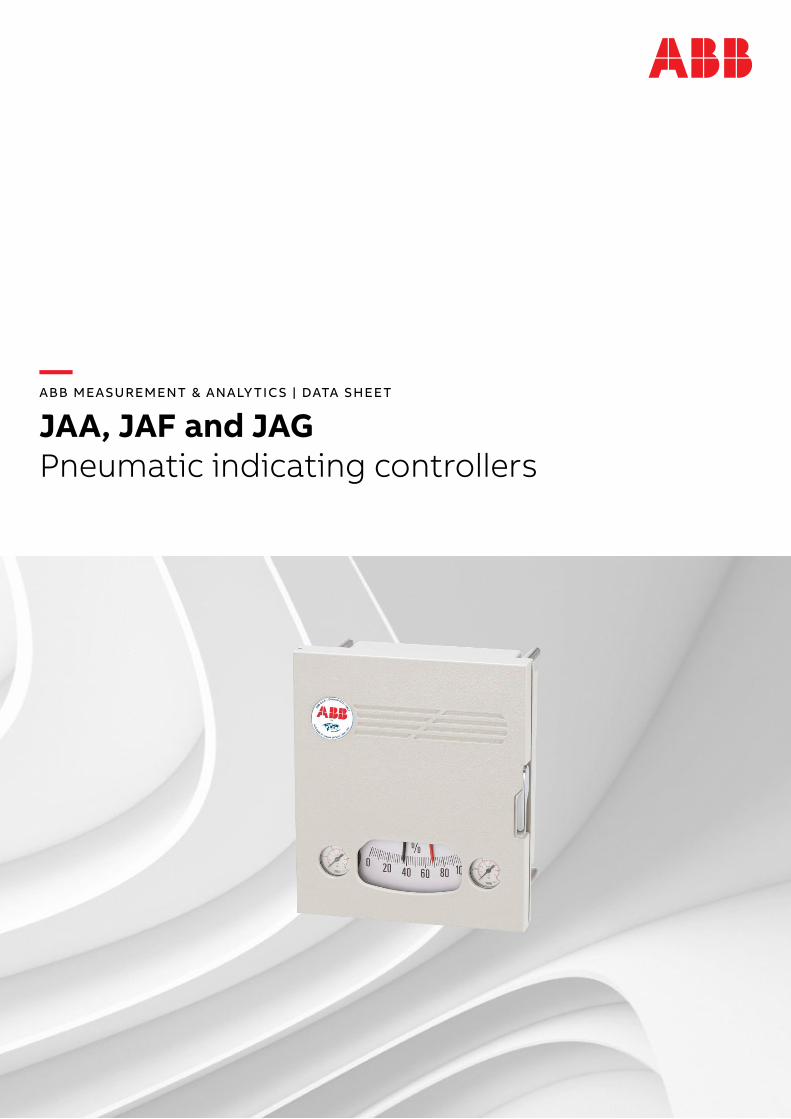
the campo series mod. JAx pneumatic indicating controllersare designed to measure and control process variable as pressure and temperature. JAx models can be equipped with a different primary measuring element as detailed hereafter.
model JAA is a single-point pneumatic instrument, which measures, indicates and controls pressure.it is designed to be used together with a spiral Bourdon tubemeasuring element.the measuring element model dBt is a unit comprising aspiral or “c” Bourdon tube and a process connection linkedtogether by a connecting pipe.the Bourdon tube is directly connected to a process and theincrease in process pressure is measured by the Bourdontube. movement of the Bourdon tube is transferred to theelement by a linkage arrangement.
model JAF is a single-point pneumatic instrument, which indicates and controls process measurements transmitted as proportional pneumatic signals from remote transmitter.
model JAG is a single-point pneumatic instrument, which measures, indicates and controls temperature.it is designed for use with a gas filled measuring element.the thermal system model dte comprises a gas filled thermometric sensor (bulb) and a steel Bourdon tube, connected by a capillary tube.it operates on a principle of gas expansion, to convert process fluid temperature changes into a proportional bourdontube motion.the dte model is designed to operate campo instrumentsseries to provide monitoring and controlling of process fluidtemperature up to 400 °c.the calibration range is normally chosen according to thevalue and variations of the measured variable. For the bestmeasuring conditions consider the following notes:
• for temperatures measurements below 0°c, the zero suppression of the instruments can not exceed the 60% of calibrated span.
• When the lower value of the calibration range is higher than 0°c, zero elevation should not exceed the 25% (for gas filling) of the span.
—Technical caracteristics
Control unitthe control unit is based on the motion-balance principle:motion of the pneumatic feedback bellows unit balances the motion of the measuring element.
Control modes and control actionin addition to the standard continuous modes (P,Pi,Pid), the On-OFF control is also available.it is possible to operate with direct or reverse action, rotating in the required direction the dial connected to the flapper-nozzle amplifier unit, without further calibration of the control unit.
Desired valueVersions are available for internal or remote setpoint.internal setpoint can be adjusted internally or by an external knob, allowing to set the desired value without opening the instrument door. external setpoint requires the connection of the relevant pneumatic signal on the rear of the instrument.
Auto/manual switchingthe instrument can be selected with two possible variants:• with external A/m module that consist of a sub-panel,
complete with a pressure reducer and A/m switch, attached to the case of the instrument.
• with integral A/m module incorporated in the case of the instrument. the manual pressure reducer and A/m switch are fitted to the bottom of the instrument itself.
Output and supply gaugesthe indicating gauges are embedded in the front case and have a diameter of 40 mm with circular scale.
Case and doormade of die-cast aluminium with anti-corrosive painting , the case has a protection according to iPX4.
Scale100 mm black horizontal sector scale with white graduations.Green setpoint pointer for easy reading even whenoverlapping the red fluorescent measured variable pointer.the scale has a safety glass window protection.
AlarmsPneumatic or electric type alarms are available on request, activated on minimum or maximum value of the variable.
4 JA A, JAF And JAG PNEUMATIC INdICATINg CoNTrollErs | ds/JAx_dBT_dTE-EN rev. H
—Specifications
INDICATING CONTROLLERS (JAA, JAF, JAG)Pneumatic supply
• nominal: 140 kPa; 1.4 bar; 20 psi• minimum: 125 kPa; 1.25 bar; 18 psi• maximum: 175 kPa; 1.75 bar; 25 psi
Input/output signals • 20 to 100 kPa• 0.2 to 1 bar• 3 to 15 psig
Air consumption (steady state)0.05 nm3/h (@ 1.4 bar supply)
Repeatability0.5%
Accuracy2%
Alarmspneumatic switch or 24 V dc 2A (factory selectable n/O or n/c)
Control functionsP, Pi, Pid, On-OFF
Control mode adjustments• Proportional: 0 to 200 %• integral: 0.15 to 15 rep/min• derivative: 0 to 5 min/rep
Ambient temperature limits- 30° to +80°c (-22° to +176°F)
Indicator pointers colour
• measured variable: red• set-point: black
Mountingvertically on wall, panel or on 2in (60 mm) pipe
Case and coveraluminium with gray painting rAl7032
Pneumatic connections1/4 in. nPt female on rear of instrument, with fitting for 4 x 6 mm pipe size
Shipping detailsnet weight: 6.5 kg (14 lb) approx. without measuring element
Packingexternal cardboard box with one or more instruments individually packed in single transparent bag.
5JA A, JAF And JAG PNEUMATIC INdICATINg CoNTrollErs | ds/JAx_dBT_dTE-EN rev. H
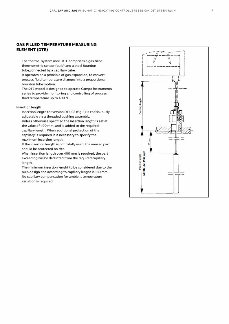
GAS FILLED TEMPERATURE MEASURING ELEMENT (DTE)
the thermal system mod. dte comprises a gas filled thermometric sensor (bulb) and a steel Bourdon tube,connected by a capillary tube.it operates on a principle of gas expansion, to convert process fluid temperature changes into a proportional bourdon tube motion.the dte model is designed to operate campo instrumentsseries to provide monitoring and controlling of process fluid temperature up to 400 °c.
Insertion lengthinsertion length for version dte 02 (fig. 1) is continuouslyadjustable via a threaded bushing assembly.unless otherwise specified the insertion length is set at the value of 400 mm. and is added to the required capillary length. When additional protection of the capillary is required it is necessary to specify the maximum insertion length. if the insertion length is not totally used, the unused part should be protected on site.When insertion length over 400 mm is required, the partexceeding will be deducted from the required capillary length.the minimum insertion lenght to be considered due to the bulb design and according to capillary lenght is 180 mm.no capillary compensation for ambient temperature variation is required.
6 JA A, JAF And JAG PNEUMATIC INdICATINg CoNTrollErs | ds/JAx_dBT_dTE-EN rev. H
—
...Specifications
GAS FILLED TEMPERATURE MEASURING ELEMENT (DTE)
capillary tube materialAisi 316 ss.
Capillary tube protectionnone or Aisi 316 ss flexible pipe (selectable).
FillingGas.
Maximum capillary length15 m.
Measuring range-80 to 500 °c (-112 to 932 °F)
Bulb diameter13 mm.
Span limits50 and 500 °c (122 and 932 °F)
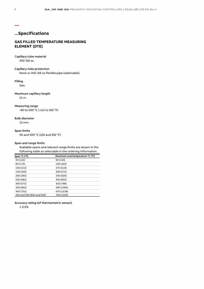
Span and range limitsAvailable spans and relevant range limits are shown in the following table as selectable in the ordering information.
Span °C (°F) Maximum overtemperature °C (°F)
50(122) 60(140)
80(176) 160(320)
100(212) 270(518)
150(302) 300(572)
200(392) 330(626)
250(482) 350(662)
300(572) 420(788)
350(662) 590(1094)
400(752) 670(1238)450and500(842and932) 700(1292)
Accuracy rating (of thermometric sensor)± 0.5%
7JA A, JAF And JAG PNEUMATIC INdICATINg CoNTrollErs | ds/JAx_dBT_dTE-EN rev. H
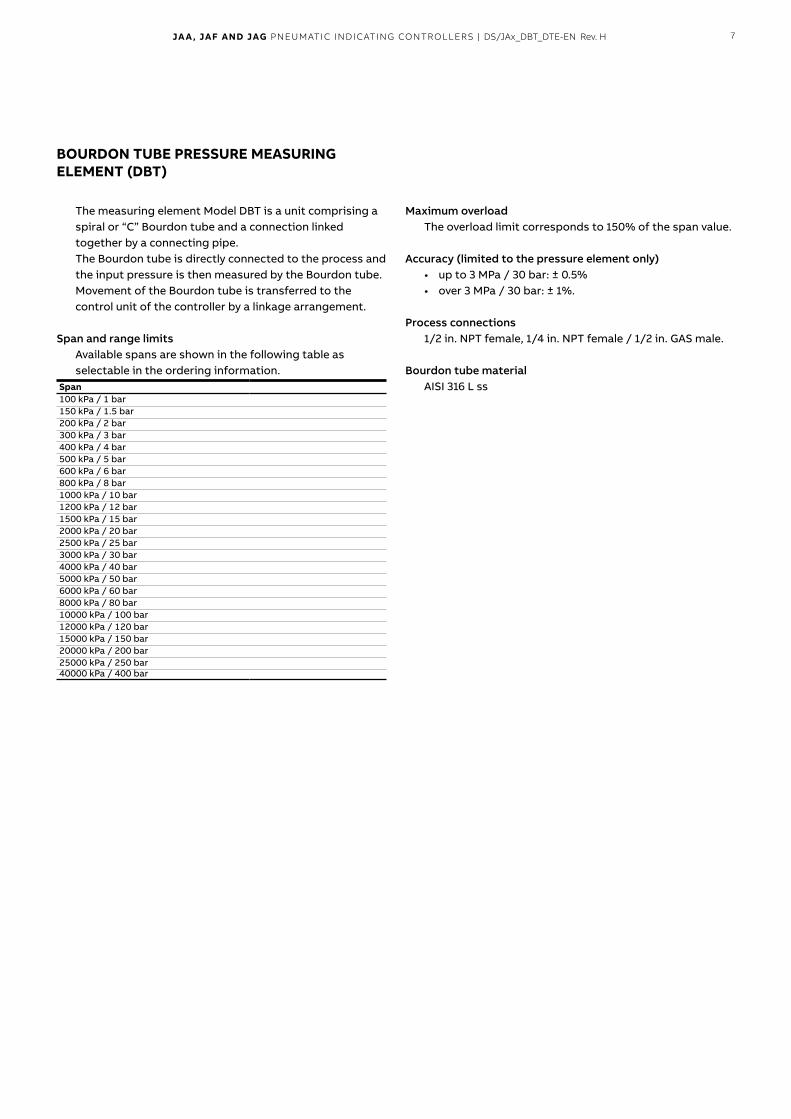
BOURDON TUBE PRESSURE MEASURING ELEMENT (DBT)
the measuring element model dBt is a unit comprising aspiral or “c” Bourdon tube and a connection linked together by a connecting pipe.the Bourdon tube is directly connected to the process and the input pressure is then measured by the Bourdon tube. movement of the Bourdon tube is transferred to thecontrol unit of the controller by a linkage arrangement.
Span and range limitsAvailable spans are shown in the following table as selectable in the ordering information.
Span100kPa/1bar150kPa/1.5bar 200kPa/2bar 300kPa/3bar 400kPa/4bar 500kPa/5bar 600kPa/6bar 800kPa/8bar 1000kPa/10bar 1200kPa/12bar 1500kPa/15bar 2000kPa/20bar 2500kPa/25bar 3000kPa/30bar 4000kPa/40bar 5000kPa/50bar 6000kPa/60bar 8000kPa/80bar 10000kPa/100bar 12000kPa/120bar 15000kPa/150bar 20000kPa/200bar 25000kPa/250bar 40000kPa/400bar
Maximum overloadthe overload limit corresponds to 150% of the span value.
Accuracy (limited to the pressure element only)• up to 3 mPa / 30 bar: ± 0.5%• over 3 mPa / 30 bar: ± 1%.
Process connections1/2 in. nPt female, 1/4 in. nPt female / 1/2 in. GAs male.
Bourdon tube materialAisi 316 l ss
8 JA A, JAF And JAG PNEUMATIC INdICATINg CoNTrollErs | ds/JAx_dBT_dTE-EN rev. H
—
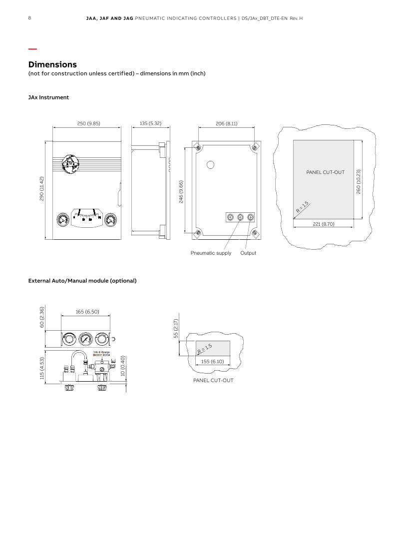
Dimensions(not for construction unless certified) – dimensions in mm (inch)
JAx Instrument
250 (9.85)
290
(11.
42)
135 (5.32) 206 (8.11)
246
(9.6
6)
221 (8.70)
260
(10.
23)PANEL CUT-OUT
R = 1.5
External Auto/Manual module (optional)
165 (6.50)
60 (2
.36)
115
(4.5
3)
10 (0
.40
)
155 (6.10)
R = 1.5
55 (2
.17)
PANEL CUT-OUT
Pneumatic supply Output
9JA A, JAF And JAG PNEUMATIC INdICATINg CoNTrollErs | ds/JAx_dBT_dTE-EN rev. H
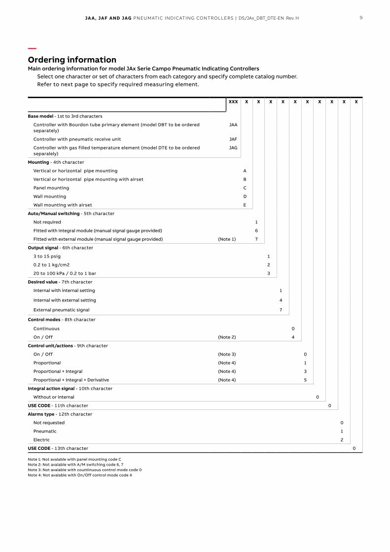
—Ordering informationMain ordering information for model JAx Serie Campo Pneumatic Indicating Controllers
select one character or set of characters from each category and specify complete catalog number.refer to next page to specify required measuring element.
XXX X X X X X X X X X X
Base model-1stto3rdcharacters
controller with Bourdon tube primary element (model dBt to be ordered separately)
JAA
controller with pneumatic receive unit JAF
controller with gas filled temperature element (model dte to be ordered separalely)
JAG
Mounting-4thcharacter
Vertical or horizontal pipe mounting A
Vertical or horizontal pipe mounting with airset B
Panel mounting c
Wall mounting d
Wall mounting with airset e
Auto/Manual switching -5thcharacter
not required 1
Fitted with integral module (manual signal gauge provided) 6
Fitted with external module (manual signal gauge provided) (Note1) 7
Output signal -6thcharacter
3to15psig 1
0.2to1kg/cm2 2
20to100kPa/0.2to1bar 3
Desired value -7thcharacter
internal with internal setting 1
internal with external setting 4
external pneumatic signal 7
Control modes -8thcharacter
continuous 0
On / Off (Note2) 4
Control unit/actions -9thcharacter
On / Off (Note3) 0
Proportional (Note4) 1
Proportional + integral (Note4) 3
Proportional + integral + derivative (Note4) 5
Integral action signal -10thcharacter
Without or internal 0
USE CODE -11thcharacter 0
Alarms type -12thcharacter
not requested 0
Pneumatic 1
electric 2
USE CODE -13thcharacter 0
note 1: not avalable with panel mounting code cnote 2: not avalable with A/m switching code 6, 7note 3: not avalable with countinuous control mode code 0note 4: not avalable with On/Off control mode code 4
10 JA A, JAF And JAG PNEUMATIC INdICATINg CoNTrollErs | ds/JAx_dBT_dTE-EN rev. H
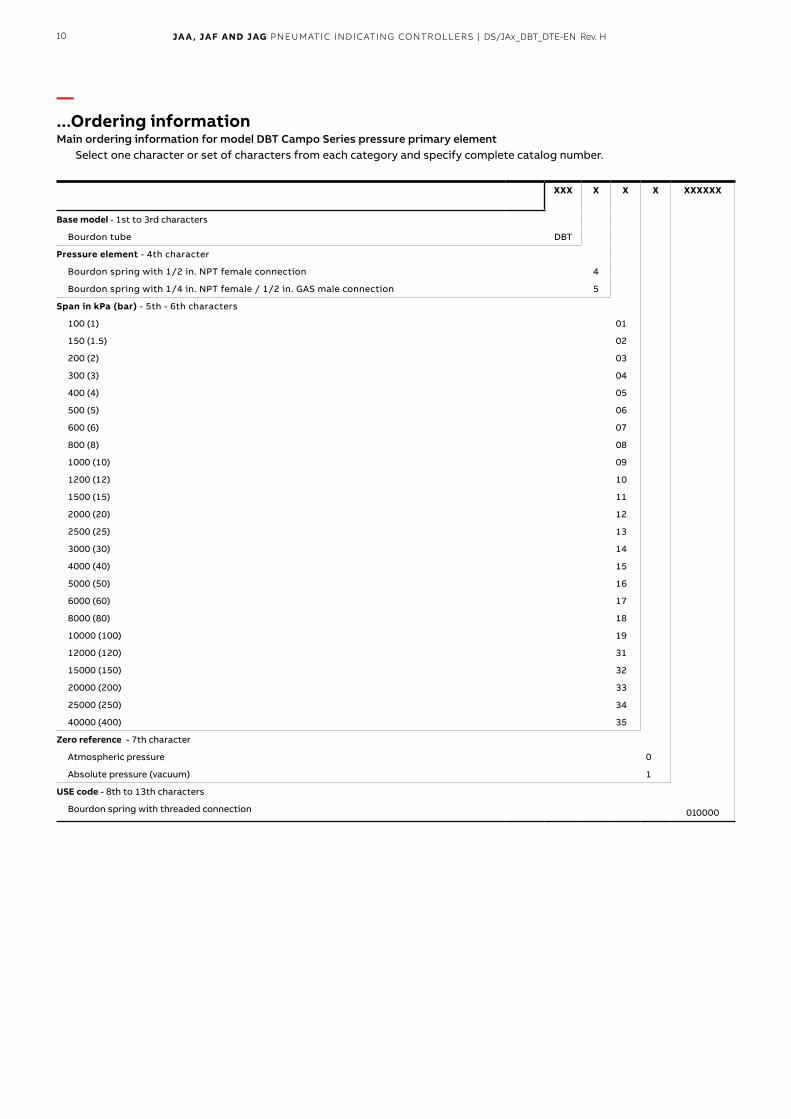
—...Ordering informationMain ordering information for model DBT Campo Series pressure primary element
select one character or set of characters from each category and specify complete catalog number.
XXX X X X XXXXXX
010000
Base model-1stto3rdcharacters
Bourdon tube dBt
Pressure element -4thcharacter
Bourdonspringwith1/2in.NPTfemaleconnection 4
Bourdonspringwith1/4in.NPTfemale/1/2in.GASmaleconnection 5
Span in kPa (bar) -5th-6thcharacters
100(1) 01
150(1.5) 02
200(2) 03
300(3) 04
400(4) 05
500(5) 06
600(6) 07
800(8) 08
1000(10) 09
1200(12) 10
1500(15) 11
2000(20) 12
2500(25) 13
3000(30) 14
4000(40) 15
5000(50) 16
6000(60) 17
8000(80) 18
10000(100) 19
12000(120) 31
15000(150) 32
20000(200) 33
25000(250) 34
40000(400) 35
Zero reference -7thcharacter
Atmospheric pressure 0
Absolute pressure (vacuum) 1
USE code -8thto13thcharacters
Bourdon spring with threaded connection
11JA A, JAF And JAG PNEUMATIC INdICATINg CoNTrollErs | ds/JAx_dBT_dTE-EN rev. H
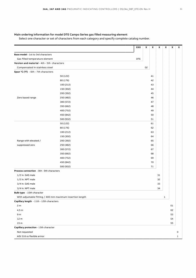
Main ordering information for model DTE Campo Series gas filled measuring elementselect one character or set of characters from each category and specify complete catalog number.
XXX X X X X X X
Base model-1stto3rdcharacters
Gas filled temperature element dte
Version and material -4th-5thcharacters
compensated in stainless steel 02
Span °C (°F) -6th-7thcharacters
50(122) 41
80(176) 42
100(212) 43
150(302) 44
200(392) 45
Zero based range 250(482) 46
300(572) 47
350(662) 48
400(752) 49
450(842) 50
500(932) 51
50(122) 61
80(176) 62
100(212) 63
150(302) 64
range with elevated / 200(392) 65
suppressed zero 250(482) 66
300(572) 67
350(662) 68
400(752) 69
450(842) 70
500(932) 71
Process connection -8th-9thcharacters
1/2in.GASmale 31
1/2in.NPTmale 32
3/4in.GASmale 33
3/4in.NPTmale 34
Bulb type -10thcharacter
Withadjustablefitting/400mmmaximuminsertionlength 1
Capillary length -11th-12thcharacters
2m 01
4.5m 02
9m 53
12m 54
15m 55
Capillary protection -13thcharacter
not requested 0
AISI316ssflexiblearmor 1

DS
/JA
x_D
BT_
DT
E-E
N R
ev. H
11.
2018
—ABB Ltd. Measurement & AnalyticsHoward Road St. Neots Cambridgeshire PE19 8EU UK Tel: +44 (0)1480 475321 Fax: +44 (0)1480 217948
ABB Inc. Measurement & Analytics125 E. County Line Road Warminster PA 18974 USA Tel: +1 215 674 6000 Fax: +1 215 674 7183
abb.com/measurement
ABB S.p.A. Measurement & AnalyticsVia Luigi Vaccani 4 22016 Tremezzina Loc. Ossuccio (CO) Italy Tel: +39 0344 58111
We reserve the right to make technical changes or modify the contents of this document without prior notice. With regard to purchase orders, the agreed particulars shall prevail. ABB does not accept any responsibility whatsoever for potential errors or possible lack of information in this document.
We reserve all rights in this document and in the subject matter and illustrations contained therein. Any reproduction, disclosure to third parties or utilization of its contents – in whole or in parts – is forbidden without prior written consent of ABB.
© Copyright 2018 ABBAll rights reserved 3KXP900103R1001