jamming-resistant broadcast communication without shared … · jamming-resistant broadcast...
TRANSCRIPT
Jamming-resistant Broadcast Communication without Shared Keys
Christina PopperSystem Security Group
ETH Zurich, [email protected]
Mario StrasserCommunication Systems Group
ETH Zurich, [email protected]
Srdjan CapkunSystem Security Group
ETH Zurich, [email protected]
Abstract
Jamming-resistant broadcast communication is crucialfor safety-critical applications such as emergency alertbroadcasts or the dissemination of navigation signals inadversarial settings. These applications share the needfor guaranteed authenticity and availability of messageswhich are broadcasted by base stations to a large andunknown number of (potentially untrusted) receivers.Common techniques to counter jamming attacks suchas Direct-Sequence Spread Spectrum (DSSS) and Fre-quency Hopping are based on secrets that need to beshared between the sender and the receivers before thestart of the communication. However, broadcast anti-jamming communication that relies on either secret pair-wise or group keys is likely to be subject to scalabil-ity and key-setup problems or provides weak jamming-resistance, respectively. In this work, we therefore pro-pose a solution called Uncoordinated DSSS (UDSSS)that enables spread-spectrum anti-jamming broadcastcommunication without the requirement of shared se-crets. It is applicable to broadcast scenarios in whichreceivers hold an authentic public key of the sender butdo not share a secret key with it. UDSSS can handle anunlimited amount of receivers while being secure againstmalicious receivers. We analyze the security and latencyof UDSSS and complete our work with an experimentalevaluation on a prototype implementation.
1 Introduction
Due to the shared use of the communication medium,wireless radio communication is not only vulnerable totraditional attacks such as eavesdropping and messagesynthesis but also to active jamming attacks [2, 20]. Ina signal jamming attack, the attacker emits a jammingsignal while the legitimate transmission is taking place,thus achieving a denial-of-service (DoS) by blocking,modifying, annihilating, or overwriting the original sig-
nal. Well-known, effective countermeasures against sig-nal jamming attacks are spread-spectrum techniques, inparticular Direct-Sequence Spread Spectrum (DSSS) andFrequency Hopping Spread Spectrum (FHSS) [23]. Forthese techniques to work, the receivers are required toshare secret keys with the sender prior to their anti-jamming communication; these keys enable them to de-rive identical spreading codes or hopping sequences.Shared secrets are also the basis of proposed anti-jamming broadcast schemes [6, 8].
The requirement of pre-shared secret keys, however,imposes limits on the use of common spread-spectrumtechniques for anti-jamming communication in scenarioswhere such secret keys cannot be pre-shared (but whichinstead rely on, e.g., public-key certificates). This prob-lem (i.e., the lack of techniques for jamming resistancewithout shared secret keys) was recently observed in [4]and [24] in the context of pairwise communication.
In this work, we focus on a related but different prob-lem for broadcast communication: How to enable ro-bust anti-jamming broadcast without shared secret keys?Typical broadcast applications share the need for authen-ticity and availability of messages that are transmitted bybase stations (senders) to a large, unknown number ofpotentially untrusted (malicious or selfish) receivers. Insuch settings, a sender communicates to a dynamic set oftrusted receivers (i.e., the nodes are honest but may beunknown to the sender due to receiver dynamics) or tountrusted receivers (which might be interested in obtain-ing the information themselves but depriving others ofit). In both cases, basing the anti-jamming communica-tion on pre-shared keys is not an option because (honest)nodes join the setting after the key deployment or be-cause malicious nodes may misuse shared keys for jam-ming. We can best illustrate this by an example:
A governmental authority needs to inform the publicabout the threat of an imminent attack. For disseminat-ing information about the risk, a message could containthe level of risk, a timestamp, the physical area of risk,
and the signature of the central authority (CA). Note thatif DSSS was used with a (public) spreading code thatis known to the attacker or if no spreading was used atall for the transmission, the attacker could easily disruptthe transmission of the message by jamming, thus block-ing the propagation of the warning within her transmis-sion radius. The information transferred in this settingis not secret, hence eavesdropping is not considered arisk. What is crucial is the dissemination (broadcast) ofauthentic information to as many receivers as possiblewithin a reasonable timeframe (seconds to few minutes).
As a solution to the described problem, we proposea scheme called Uncoordinated DSSS (UDSSS) that en-ables authentic spread-spectrum anti-jamming broadcastwithout the requirement of shared secrets. UDSSS fol-lows a similar approach as DSSS, it differs, however,in the following aspect: the spreading code is not pre-defined but chosen by the sender randomly out of a setof publicly available codes. Since no receiver can pre-dict the choice of the sender, UDSSS prevents dishon-est receivers from interfering with the communication (toother receivers) while it enables them to obtain the infor-mation themselves. After a certain time, every receiverwill succeed in identifying the correct spreading codeand its synchronization, thus despreading the signal. Therequired despreading time depends on the coding strat-egy, the size of the spreading code set, and on the re-ceivers’ processing capabilities; we analyze this in detail.Although UDSSS is inherently less efficient than DSSS,it enables broadcast anti-jamming communication in sce-narios in which DSSS cannot be used. Besides the exam-ple described above, an important application of UDSSSis the jamming-resilient dissemination of navigation sig-nals. As we will show in Section 7, UDSSS enables notonly anti-jamming localization for broadcast navigationsystems (GPS or similar systems), but it also inherentlyprotects them against a wide range of location-spoofingattacks. We will also show that UDSSS can achieve thesame performance as DSSS in the absence of jamming.
In summary, the main contributions of this work are:• We identify anti-jamming broadcast without shared
keys as a relevant problem and we show that it canbe addressed using uncoordinated spread-spectrumtechniques.• We propose a scheme called Uncoordinated DSSS
that supports broadcast anti-jamming communica-tion without shared keys and enables communica-tion in scenarios in which DSSS cannot be used.• We analyze the performance of UDSSS. We show
that a performance comparable to DSSS can beachieved in the absence of jamming and that the ex-pected time for a message transmission to ten re-ceivers takes less than 30 s on state-of-the-art sys-tems under high jamming-probabilities.
• We demonstrate the feasibility of UDSSS by a pro-totype implementation on a software-defined radioplatform [10]; the reception of a typical messagetakes well below 20 s for 21 dB processing gain onthis system. We note that this time can further besignificantly reduced on a purpose-built platform(e.g., like the ones used for GPS receivers).
The remainder of the paper is organized as follows:We give background information on DSSS in Section 2and describe the system and attacker models in Section 3.In Section 4, we present our UDSSS scheme. We analyzeits security in Section 5 and its performance in Section 6,including the presentation of our implementation results.In Section 7, we discuss possible applications of UDSSS.Finally, in Section 8, we describe related work and weconclude our paper in Section 9.
2 Background: DSSS
In DSSS, the data signal is modulated with a continu-ous, pre-defined spreading signal of a higher frequency,also called the chipping sequence. During the modula-tion, the data signal gets spread in the frequency domainand thus becomes resistant against (narrow-band) inter-ference. The resulting signal is modulated (e.g., usingphase-shift keying) and – given a sufficiently high fre-quency of the spreading signal – becomes hidden in thenoise of the wireless channel. The processing gain of thecommunication system (indicating the ratio by which in-terference can be suppressed relative to the original sig-nal) defines the required length N of the DSSS spread-ing code, determining the spreading signal. More pre-cisely, given a certain data bit time Tb and a target pro-cessing gain defined as 10 log10
Tb
Tcin decibel (dB), we
get N = Tb/Tc, where Tc is the time of a modulated sig-nal chip (a low signal-to-noise ratio requires Tc � Tb).A typical processing gain of spread-spectrum systems isbetween 20 dB and 60 dB and results from a chip lengthN ∈ {100, . . . , 106}.
In anti-jamming applications, the DSSS spreading sig-nal is secret and shared only by the sender and legit-imate receivers. This can be achieved by a shared se-cret key that is used to seed a pseudo-random generatorat the sender and the receivers. The generator outputsa (pseudo-random) chipping sequence which is used tospread the message. In order to despread the signal, thereceivers apply a symmetric operation and correlate thereceived signal with a synchronized replica of the spread-ing code. Except for the secret code, all other commu-nication parameters (modulation, frequency band, etc.)are public. For the discussion of DSSS we assume thatthe receivers are synchronized to the sender (later, wewill show how we remove this assumption in UDSSS).The synchronization includes both bit and chip time syn-
chronization to the sent signal as well as synchronizationwith respect to the used spreading code, i.e., the receiversknow which code to apply at which point in time in or-der to despread the received signal. We refer to relatedliterature for a comprehensive discussion of efficient syn-chronization techniques [2, 20, 23].
In more details, for spreading a messageM , the senderuses a spreading sequence c0 = (c0,1, c0,2, . . . , c0,`)composed of ` binary NRZ (non-return to zero) spread-ing codes, |c0,i| = N . Typical spreading codes usedfor DSSS are pseudo-randomly created sequences [23]and codes with well-defined properties such as Walsh-Hadamard [11] or Gold-codes [20]. The sender spreadsM by applying code c0,1 to the first b bits of M , c0,2to the second b bits and so forth, where b denotes therepetition factor in the use of the spreading codes. Byexpressing the codes in the time domain, we can definea function c0(t) = c0,i[j] for i = bt/bTbc mod N andj = bt/Tcc mod N , where Tb (Tc) is the data bit (chip)time. The spreading operation can then be written asd(t) · c0(t), where d(t) is the data signal that carries themessage. The sender modulates and transmits the result.
Upon signal reception, each receiver demodulates thesignal and samples it (sampling rate Rs ≥ 2/Tc). Itstores the samples in a cyclic buffer which has the ca-pacity to store samples of several message bits, (i.e., forthe duration of Ts = kTb, k > 1 ∈ N). Then, the re-ceiver despreads the data stored in the buffer by comput-ing s :=
∑TbRs
i=0 s[i]c0(ti) for each data bit, where s[i]denotes the i-th value in the buffer and ti the time whenit was sampled. Finally, the result of the bit integrations is used to determine the received bit di. We assumea simple bit decoder that outputs 1 (0) if the integrationyields a value greater (lower) than 0 (i.e., di = dse). Fi-nally, after all data bits have been despread, the correct-ness of the despreading operation is verified by means ofthe message decoding.
3 System and Attacker Models
3.1 System ModelOur system consists of a sender A and a set of receivers.The goal of the sender is to enable anti-jamming broad-cast to the receivers in the presence of communicationjamming. We assume that each device is equipped witha radio frontend with transmission and reception capa-bilities in a corresponding frequency band and that thereceivers are computationally capable of efficiently per-forming (e.g., ECC-based) public-key operations. In ad-dition, each receiver holds an authentic public key of thesender or of the central authority (CA) that can certifythe sender’s public key. The CA may be off-line at thetime of communication.
In our model, PA denotes the strength of A’s signalarriving at a receiver B; PA depends on the strength ofthe signal sent by A, on the distance between the senderand the receiver as well as on large- and small-scale fad-ing and interference effects [25,26]. We denote by Pt theminimal required signal strength at the receiver B suchthatB can successfully decode the signal. In this context,the transmission between A and B in a setting without(active) interference will be successful if i) PA ≥ Pt, ifii) A and B use the same spreading code, and if iii) Buses the correct synchronization in its despreading oper-ation (code time and carrier frequency synchronization).
3.2 Attacker Model
We adopt the attacker model from [24] and consider anomnipresent but computationally bounded adversary Jwith unlimited power supply that is able to eavesdropand insert messages arbitrarily but can only alter or erasemessages by adding her own (energy-limited) signals tothe wireless medium; that is, she cannot disable the com-munication channel by blocking the propagation of sig-nals (e.g., by placing a Faraday cage around a node).The goal of the attacker is to prevent all communicationbetween the sender A and all or some of the receivers.In order to achieve this, the attacker is not restricted tomessage jamming but can also modify existing or insertnew messages. More precisely, the attacker can chooseamong the following actions:• She can jam messages by transmitting high-power
signals that cause the original signal to become un-readable by the receiver. The fraction of the mes-sage that the attacker has to interfere with to suc-cessfully jam depends on the used coding scheme(e.g., 13% of the message size [16]).• She can modify messages by either flipping single
message bits or by entirely overshadowing originalmessages. In either case, in this attack the messagesremain readable by the receiver.• She can insert messages that she generated herself
or reuse previously overheard messages. Depend-ing on the signal strength and used spreading codes,the inserted messages might interfere with regulartransmissions.
In addition to these types of attacks, we follow previ-ous classifications [20] and distinguish different types ofattackers: static, sweep, random, and reactive jammers.Static, sweep, and random jammers do not sense for on-going transmissions but jam the channel permanently;they only differ in the regularity of their jamming sig-nals. Reactive jammers initially solely sense for ongoingtransmissions and start jamming only after the detectionof a message transfer; we express the strength of reac-tive jammers by their despreading performance ΛB(N),
denoting the number of spreading codes the attacker canapply and check per time unit. Repeater jammers [12] area subclass of reactive jammers that intercept the signal,low-noise amplify, filter and re-radiate it without requir-ing or getting knowledge of the used spreading codes.Hybrid jammers are a combination of the above typesthat jam while searching for message transmissions.
For all attacker types, we assume a finite maximaltransmission power and bandwidth. We denote by PJthe maximal signal strength that the attacker is able toachieve at a receiver B; the attacker can split PJ over anarbitrary number of parallel signal transmissions. GivenPA, the strength of A’s signal at B, we denote by Pj andPo the minimal required strength of the attacker’s sig-nal at B in order to jam or overshadow a message sentfrom A to B, respectively, provided that the attacker isaware of the used code sequence and its synchroniza-tion. We assume Pt ≤ PA and Pj < Po. We furtherassume that PJ < µPt, where µ denotes the number ofpossible transmissions, i.e., the attacker is not capableof jamming all possible transmissions in parallel; µ de-pends on the number of available spreading codes and onthe attacker’s bit and chip synchronization.
4 Jamming-Resistant Broadcast: UDSSS
In this section, we introduce our UDSSS (UncoordinatedDSSS) scheme. UDSSS is an anti-jamming modulationtechnique based on the concept of DSSS, however, itdoes not rely on pre-shared spreading sequences. In con-trast to anti-jamming DSSS communication, where thespreading sequence is secret and shared exclusively bythe communication partners, in UDSSS, a public set Cof spreading sequences is used by the sender and the re-ceivers. C is not secret and may be known to the at-tacker. To transmit a message, the sender randomly se-lects a spreading sequence from the code set and spreadsthe message with this sequence. The receivers record thesignal on the channel and despread the message by ap-plying sequences from C using a trial-and-error method.
The receivers using UDSSS are not time-synchronizedto the sender with respect to the spread signal, i.e., theydo not know the message bit or chip synchronization.In order to compensate for this (as well as for messagelosses due to jamming), the sender sends the messagerepeatedly and the receivers apply a sliding window ap-proach to synchronize to the transmission. The efficiencyof UDSSS is therefore determined i) by the time that thereceivers need to find the right spreading code and itssynchronization (we will analyze this in detail in Sec-tion 6) and ii) by the attacker’s jamming success (ana-lyzed in Section 5). Given that, in UDSSS, the receiversneed to search through a set of codes and synchroniza-tion windows in order to despread the received message,
UDSSS is inherently less efficient than DSSS. However,it provides important advantages over DSSS:• UDSSS enables anti-jamming communication be-
tween nodes that are within each others’ transmis-sion ranges but do not share a secret, and• UDSSS supports broadcast anti-jamming commu-
nication for dynamic groups of untrusted receivers.UDSSS requires the receivers to store all chips re-
ceived and to analyze them retrospectively to find theused spreading code. The time this takes defines thelatency of the communication. The performance andjamming-resistance of UDSSS can be increased by usingmultiple senders (in contrast to DSSS). More precisely,we consider m ≥ 1 parallel broadcast transmissions ofthe same message with different spreading codes. Thiscan be achieved by one sender transmitting m signals inparallel—each spread with a different spreading code—or by using m separate sending devices.
In what follows, we describe the details of the UDSSSoperations at the sender(s) and the receivers and discusssuitable choices of the UDSSS spreading code set.
4.1 UDSSS Transmission
We envisage one sending device, but for generality, ourdescription includes one or multiple senders that trans-mit the same message in parallel on m ≥ 1 channels us-ing the code sets C1, . . . , Cm (not necessarily distinct).For transmitting message M , |M | ≤ `, each sender re-peatedly selects a fresh, i.e. randomly selected, code se-quence cs ∈ Ci, spreads M using cs, and transmits theresulting modulated signal. For each transmission a newcode sequence is chosen; repeated messages thus get en-coded with a different code sequence on each transmis-sion (with high probability). All spreading codes arechosen to be (nearly) orthogonal (strong auto- and lowcross-correlations), hence parallel transmissions of mul-tiple senders do not (significantly) interfere with eachother; multiple transmissions using the same spreadingcode and code synchronization can be excluded by agree-ments between the senders that are, e.g., linked by wires.Each sender repeats the spreading and sending opera-tion either for a well-defined number of iterations (e.g.,for emergency alert broadcasting) or continuously (forlonger-term applications, e.g. for navigation signals).
Before the UDSSS modulation, each sender appliesthe following techniques: In order to achieve messageauthentication, sender A signs the message using its pri-vate key SKA. The sender may also include a times-tamp or sequence number in the message in order toachieve replay protection. In order to resist transmissionerrors, the sender then error-encodes the message beforethe spreading operation; error-coding makes a messageresistant to a certain number of bit errors (e.g., up to 13%
...
...
...
...
fail
...
sequencesn code
ci : ci,1 ci,2 ... ci,ℓ
despreadmessage
1 0 0 1
ci : ci,1 ci,2 ... ci,ℓ
demodulation& sampling
despread
signature verification
101101000100...
message M
channel
message M
signing
modulation
M |SKA(M)
1 0 0 1
(a) UDSSS Sender (b) UDSSS Receiver
spreadingencodingerror
1011101101000011...
cs : 10110100...
success
success
> τ?
timeoutuntil
data bits
randomlyselect
k codes ci,j
ℓ codes per code sequence
error decoding &orderarbitraryselect in
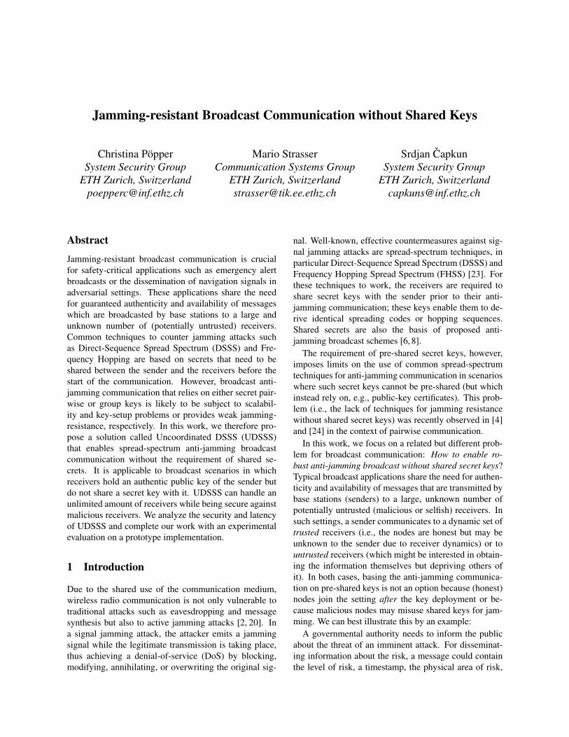
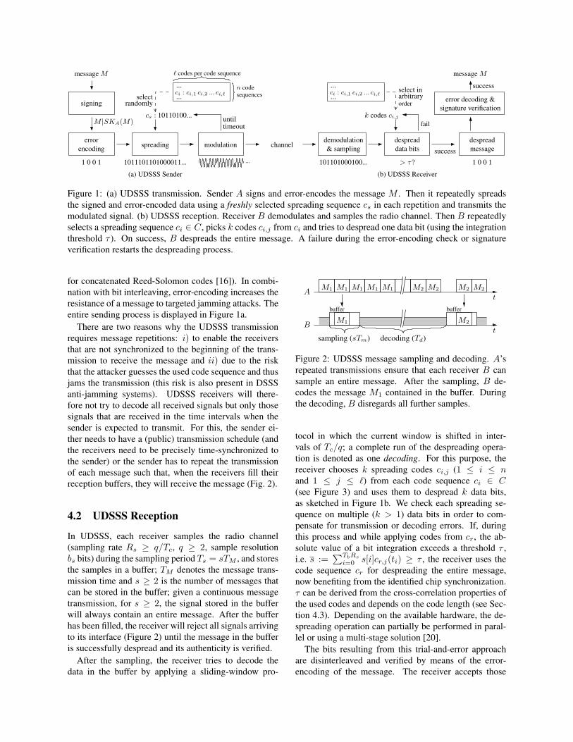
Figure 1: (a) UDSSS transmission. Sender A signs and error-encodes the message M . Then it repeatedly spreadsthe signed and error-encoded data using a freshly selected spreading sequence cs in each repetition and transmits themodulated signal. (b) UDSSS reception. Receiver B demodulates and samples the radio channel. Then B repeatedlyselects a spreading sequence ci ∈ C, picks k codes ci,j from ci and tries to despread one data bit (using the integrationthreshold τ ). On success, B despreads the entire message. A failure during the error-encoding check or signatureverification restarts the despreading process.
for concatenated Reed-Solomon codes [16]). In combi-nation with bit interleaving, error-encoding increases theresistance of a message to targeted jamming attacks. Theentire sending process is displayed in Figure 1a.
There are two reasons why the UDSSS transmissionrequires message repetitions: i) to enable the receiversthat are not synchronized to the beginning of the trans-mission to receive the message and ii) due to the riskthat the attacker guesses the used code sequence and thusjams the transmission (this risk is also present in DSSSanti-jamming systems). UDSSS receivers will there-fore not try to decode all received signals but only thosesignals that are received in the time intervals when thesender is expected to transmit. For this, the sender ei-ther needs to have a (public) transmission schedule (andthe receivers need to be precisely time-synchronized tothe sender) or the sender has to repeat the transmissionof each message such that, when the receivers fill theirreception buffers, they will receive the message (Fig. 2).
4.2 UDSSS Reception
In UDSSS, each receiver samples the radio channel(sampling rate Rs ≥ q/Tc, q ≥ 2, sample resolutionbs bits) during the sampling period Ts = sTM , and storesthe samples in a buffer; TM denotes the message trans-mission time and s ≥ 2 is the number of messages thatcan be stored in the buffer; given a continuous messagetransmission, for s ≥ 2, the signal stored in the bufferwill always contain an entire message. After the bufferhas been filled, the receiver will reject all signals arrivingto its interface (Figure 2) until the message in the bufferis successfully despread and its authenticity is verified.
After the sampling, the receiver tries to decode thedata in the buffer by applying a sliding-window pro-
BM1 M2
decoding (Td)sampling (sTm)
AM1 M2 M2 M2 M2M1 M1 M1 M1
t
t
buffer buffer
Figure 2: UDSSS message sampling and decoding. A’srepeated transmissions ensure that each receiver B cansample an entire message. After the sampling, B de-codes the message M1 contained in the buffer. Duringthe decoding, B disregards all further samples.
tocol in which the current window is shifted in inter-vals of Tc/q; a complete run of the despreading opera-tion is denoted as one decoding. For this purpose, thereceiver chooses k spreading codes ci,j (1 ≤ i ≤ nand 1 ≤ j ≤ `) from each code sequence ci ∈ C(see Figure 3) and uses them to despread k data bits,as sketched in Figure 1b. We check each spreading se-quence on multiple (k > 1) data bits in order to com-pensate for transmission or decoding errors. If, duringthis process and while applying codes from cr, the ab-solute value of a bit integration exceeds a threshold τ ,i.e. s :=
∑TbRs
i=0 s[i]cr,j(ti) ≥ τ , the receiver uses thecode sequence cr for despreading the entire message,now benefiting from the identified chip synchronization.τ can be derived from the cross-correlation properties ofthe used codes and depends on the code length (see Sec-tion 4.3). Depending on the available hardware, the de-spreading operation can partially be performed in paral-lel or using a multi-stage solution [20].
The bits resulting from this trial-and-error approachare disinterleaved and verified by means of the error-encoding of the message. The receiver accepts those
N chips per coden codesequen-ces
MM [1] M [2]
cs,1
cs
c1
c2
cs,ℓ
M [ℓ]
ℓ codes per code sequence
cn,1 cn,ℓ
cs,1 cs,2
c2,2
c1,2 c1,ℓ
cn
c1,1
c2,1
cs,ℓ
c2,ℓ
cn,2
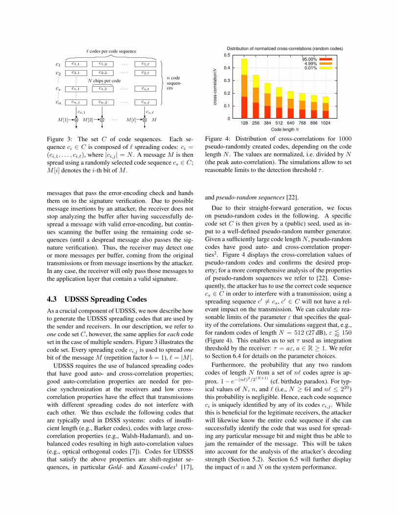
Figure 3: The set C of code sequences. Each se-quence ci ∈ C is composed of ` spreading codes: ci =(ci,1, . . . , ci,`), where |ci,j | = N . A message M is thenspread using a randomly selected code sequence cs ∈ C;M [i] denotes the i-th bit of M .
messages that pass the error-encoding check and handsthem on to the signature verification. Due to possiblemessage insertions by an attacker, the receiver does notstop analyzing the buffer after having successfully de-spread a message with valid error-encoding, but contin-ues scanning the buffer using the remaining code se-quences (until a despread message also passes the sig-nature verification). Thus, the receiver may detect oneor more messages per buffer, coming from the originaltransmissions or from message insertions by the attacker.In any case, the receiver will only pass those messages tothe application layer that contain a valid signature.
4.3 UDSSS Spreading CodesAs a crucial component of UDSSS, we now describe howto generate the UDSSS spreading codes that are used bythe sender and receivers. In our description, we refer toone code set C, however, the same applies for each codeset in the case of multiple senders. Figure 3 illustrates thecode set. Every spreading code ci,j is used to spread onebit of the message M (repetition factor b = 1), ` = |M |.
UDSSS requires the use of balanced spreading codesthat have good auto- and cross-correlation properties;good auto-correlation properties are needed for pre-cise synchronization at the receivers and low cross-correlation properties have the effect that transmissionswith different spreading codes do not interfere witheach other. We thus exclude the following codes thatare typically used in DSSS systems: codes of insuffi-cient length (e.g., Barker codes), codes with large cross-correlation properties (e.g., Walsh-Hadamard), and un-balanced codes resulting in high auto-correlation values(e.g., optical orthogonal codes [7]). Codes for UDSSSthat satisfy the above properties are shift-register se-quences, in particular Gold- and Kasami-codes1 [17],
0
0.1
0.2
0.3
0.4
0.5
128 256 384 512 640 768 896 1024
cro
ss-c
orr
ela
tion/N
Code length N
Distribution of normalized cross-correlations (random codes)
95.00%4.99%0.01%
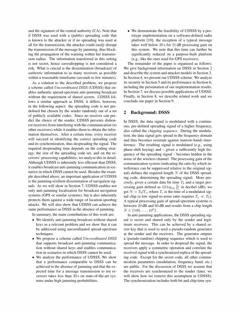
Figure 4: Distribution of cross-correlations for 1000pseudo-randomly created codes, depending on the codelength N . The values are normalized, i.e. divided by N(the peak auto-correlation). The simulations allow to setreasonable limits to the detection threshold τ .
and pseudo-random sequences [22].
Due to their straight-forward generation, we focuson pseudo-random codes in the following. A specificcode set C is then given by a (public) seed, used as in-put to a well-defined pseudo-random number generator.Given a sufficiently large code lengthN , pseudo-randomcodes have good auto- and cross-correlation proper-ties2. Figure 4 displays the cross-correlation values ofpseudo-random codes and confirms the desired prop-erty; for a more comprehensive analysis of the propertiesof pseudo-random sequences we refer to [22]. Conse-quently, the attacker has to use the correct code sequencecs ∈ C in order to interfere with a transmission; using aspreading sequence c′ 6= cs, c′ ∈ C will not have a rel-evant impact on the transmission. We can calculate rea-sonable limits of the parameter ε that specifies the qual-ity of the correlations. Our simulations suggest that, e.g.,for random codes of length N = 512 (27 dB), ε / 150(Figure 4). This enables us to set τ used as integrationthreshold by the receiver: τ = aε, a ∈ R ≥ 1. We referto Section 6.4 for details on the parameter choices.
Furthermore, the probability that any two randomcodes of length N from a set of n` codes agree is ap-prox. 1− e−(n`)2/2(N+1)
(cf. birthday paradox). For typ-ical values of N , n, and ` (i.e., N ≥ 64 and n` ≤ 220)this probability is negligible. Hence, each code sequenceci is uniquely identified by any of its codes ci,j . Whilethis is beneficial for the legitimate receivers, the attackerwill likewise know the entire code sequence if she cansuccessfully identify the code that was used for spread-ing any particular message bit and might thus be able tojam the remainder of the message. This will be takeninto account for the analysis of the attacker’s decodingstrength (Section 5.2). Section 6.5 will further displaythe impact of n and N on the system performance.
5 Security Evaluation of UDSSS
In this section, we analyze the points of attack on UDSSScommunication and, for various attacker types, derive theprobability that a message is jammed during its transmis-sion. As we will show, UDSSS provides resistance evento reactive attackers, a very strong type of attacker.
5.1 Jamming Attacks on UDSSS
An attacker has the following options for performing acode-based jamming attack on UDSSS communication:i) she can guess the spreading code and try to jam thesignal using this code, ii) she can repeat the recordedsignal, thus trying to create a collision with the origi-nal transmission, and iii) she can try to find the codeby despreading (part of) the spread signal and then usethe identified spreading sequence for jamming the rest ofthe message during its transmission. In the first case, theattacker’s jamming signal is independent of the transmis-sion she is trying to jam (representing a static, sweep, orrandom attacker); in the latter two cases, the attacker isreactive and bases her jamming signal on the detection(and analysis) of the spread signal. In the following werefer to reactive jammers that simply repeat the recordedsignal as repeater jammers and to reactive jammers thataim at finding the used spreading code as decoding jam-mers. A hybrid jammer can combine non-reactive andreactive actions.
For non-reactive (static, sweep or random) attackers(case i), the attacker’s success probability depends on thenumber of codes that she chooses from for composingher jamming signal and on the accuracy of her synchro-nization to the spread signal. Although (U)DSSS sig-nals are usually hidden in noise, they can be detectedby means of energy detectors or by their modulation-specific characteristics [9,20]. Depending on the strengthof the attacker and the processing gain achieved by themodulation, the attacker might therefore be able to re-cover a message transmission and its chip synchroniza-tion without having to decode a message; however theattacker still needs to guess the used spreading code inorder to jam the signal. In all cases, the jamming suc-cess probability of a non-reactive attacker depends onthe number of codes in the code set; this probability isfurther decreased if the attacker cannot detect the chipsynchronization (Sec. 5.2).
The purpose of using a different spreading code foreach message bit (b = 1) is to prevent successful re-play attacks from repeater jammers [12] (case ii). Dueto the low auto-correlation properties of the codes, theattacker’s repeated signal would have to arrive at the re-ceiver within one chip length Tc in order to affect thetransmission; this requires the attacker to have an (al-
tJ
tB t2t1
tA
t3
Propagation delay
M [1]
Despreading time Td (B)
TdTa Tj
TM
Tp
tj
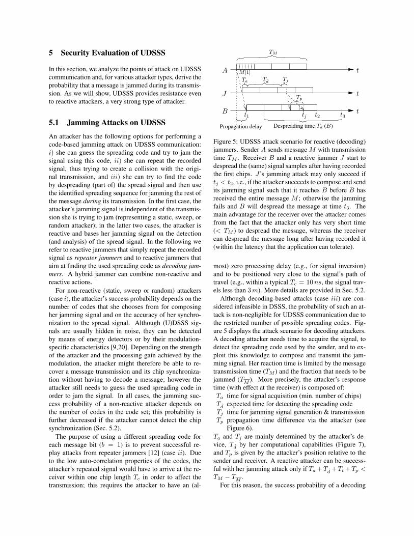
Figure 5: UDSSS attack scenario for reactive (decoding)jammers. Sender A sends message M with transmissiontime TM . Receiver B and a reactive jammer J start todespread the (same) signal samples after having recordedthe first chips. J’s jamming attack may only succeed iftj < t2, i.e., if the attacker succeeds to compose and sendits jamming signal such that it reaches B before B hasreceived the entire message M ; otherwise the jammingfails and B will despread the message at time t3. Themain advantage for the receiver over the attacker comesfrom the fact that the attacker only has very short time(< TM ) to despread the message, whereas the receivercan despread the message long after having recorded it(within the latency that the application can tolerate).
most) zero processing delay (e.g., for signal inversion)and to be positioned very close to the signal’s path oftravel (e.g., within a typical Tc = 10ns, the signal trav-els less than 3m). More details are provided in Sec. 5.2.
Although decoding-based attacks (case iii) are con-sidered infeasible in DSSS, the probability of such an at-tack is non-negligible for UDSSS communication due tothe restricted number of possible spreading codes. Fig-ure 5 displays the attack scenario for decoding attackers.A decoding attacker needs time to acquire the signal, todetect the spreading code used by the sender, and to ex-ploit this knowledge to compose and transmit the jam-ming signal. Her reaction time is limited by the messagetransmission time (TM ) and the fraction that needs to bejammed (TM ). More precisely, the attacker’s responsetime (with effect at the receiver) is composed of:Ta time for signal acquisition (min. number of chips)Td expected time for detecting the spreading codeTj time for jamming signal generation & transmissionTp propagation time difference via the attacker (see
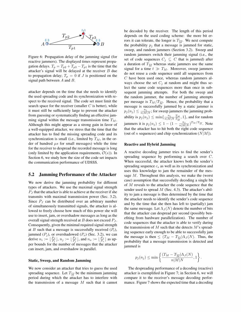
Figure 6).Ta and Tj are mainly determined by the attacker’s de-vice, Td by her computational capabilities (Figure 7),and Tp is given by the attacker’s position relative to thesender and receiver. A reactive attacker can be success-ful with her jamming attack only if Ta +Td +Tt +Tp <TM − TM .
For this reason, the success probability of a decoding
BTp1
Tp2 J Tp3
A
Figure 6: Propagation delay of the jamming signal (forreactive jammers). The displayed times represent propa-gation delays. Tp = Tp2 + Tp3 − Tp1 is the time that theattacker’s signal will be delayed at the receiver B dueto propagation delay; Tp = 0 if J is positioned on thesignal path between A and B.
attacker depends on the time that she needs to identifythe used spreading code and its synchronization with re-spect to the received signal. The code set must limit thesearch space for the receiver (smaller C is better), whileit must still be sufficiently large to prevent the attackerfrom guessing or systematically finding an effective jam-ming signal within the message transmission time TM .Although this might appear as a strong gain in favor ofa well-equipped attacker, we stress that the time that theattacker has to find the missing spreading code and itssynchronization is small (i.e., limited by TM , in the or-der of hundred µs for small messages) while the timefor the receiver to despread the recorded message is long(only limited by the application requirements, O(s)). InSection 6, we study how the size of the code set impactsthe communication performance of UDSSS.
5.2 Jamming Performance of the Attacker
We now derive the jamming probability for differenttypes of attackers. We use the maximal signal strengthPJ that the attacker is able to achieve at the receiver if shetransmits with maximal transmission power (Sec. 3.2).Since PJ can be distributed over an arbitrary numberof simultaneously transmitted signals, the attacker is al-lowed to freely choose how much of this power she willuse to insert, jam, or overshadow messages as long as theoverall signal strength received atB does not exceed PJ .Consequently, given the minimal required signal strengthat B such that a message is successfully received (Pt),jammed (Pj), or overshadowed (Po) (Sec. 3.2), we canderive ni := bPJ
Ptc, nj := bPJ
Pjc, and no := bPJ
Poc as up-
per bounds for the number of messages that the attackercan insert, jam, and overshadow in parallel.
Static, Sweep, and Random Jamming
We now consider an attacker that tries to guess the usedspreading sequence. Let TM be the minimum jammingperiod during which the attacker has to interfere withthe transmission of a message M such that it cannot
be decoded by the receiver. The length of this perioddepends on the used coding scheme: the more bit er-rors it can tolerate, the longer is TM . We next computethe probability pj that a message is jammed for static,sweep, and random jammers (Section 3.2). Sweep andrandom jammers switch their jamming signal (i.e., theset of code sequences Cj ⊆ C that is jammed) aftera duration of TM whereas static jammers use the samesignal for a time t � TM . Moreover, sweep jammersdo not reuse a code sequence until all sequences fromC have been used once, whereas random jammers al-ways choose the set Cj at random and might thus se-lect the same code sequences more than once in sub-sequent jamming attempts. For both the sweep andthe random jammer, the number of jamming attemptsper message is TM/TM . Hence, the probability that amessage is successfully jammed by a static jammer ispj(nj) ≤ nj
n|M |N ; for sweep jammers the jamming prob-
ability is pj(nj) ≤ min{ nj
n|M |NTM
TM
, 1}, and for random
jammers it is pj(nj) ≤ 1 − (1 − nj
n|M |N )TM/TM . Note
that the attacker has to hit both the right code sequence(out of n sequences) and chip synchronization (N |M |).
Reactive and Hybrid Jamming
A reactive decoding jammer tries to find the sender’sspreading sequence by performing a search over C.When successful, the attacker knows both the sender’sspreading sequence cs as well as its synchronization anduses this knowledge to jam the remainder of the mes-sage M . Throughout this analysis, we make the (worstcase) assumption that successfully decoding a single bitof M reveals to the attacker the code sequence that thesender used to spread M (Sec. 4.3). The attacker’s abil-ity to jam a message is thus determined by the time thatthe attacker needs to identify the sender’s code sequenceand by the time that she then has left to (partially) jamthe same message. Let ΛJ(N) denote the number of bitsthat the attacker can despread per second (possibly ben-efiting from hardware parallelization). The number ofcode sequences that the attacker is able to verify duringthe transmission of M such that she detects M ’s spread-ing sequence early enough to be able to successfully jamthe message is then ≤ (TM − TM )ΛJ(N). Thus, theprobability that a message transmission is detected andjammed is
pj(nj) ≤ min{
(TM − TM )ΛJ(N)n|M |N
, 1}.
The despreading performance of a decoding (reactive)attacker is exemplified in Figure 7; in Section 6, we willcompare it to the receiver’s message decoding perfor-mance. Figure 7 shows the expected time that a decoding
10-6
10-3
100
103
106
106
107
108
109
1010
1011
1012
1013
1014
1015
decoding performance (IPS)
Time to detect a message of |M| = 2000 bits length (in sec)
N
R
= 100= 2.4⋅10
9
TM
for |M| = 2000
n = 10n = 100n = 1000
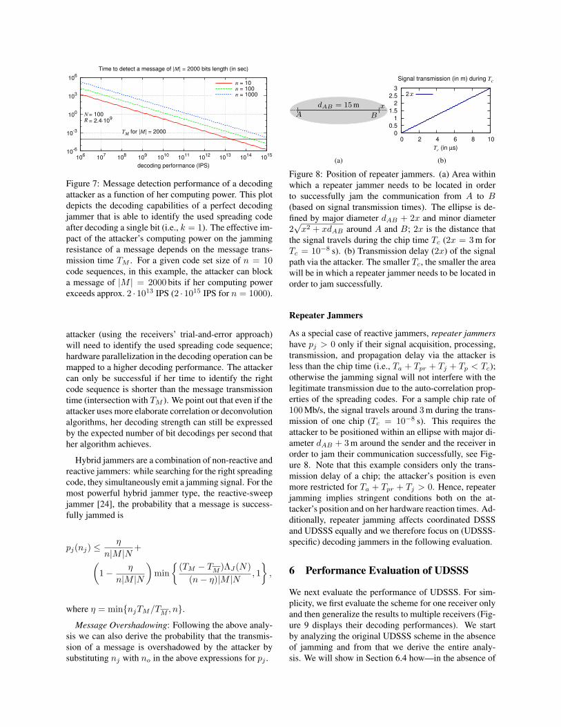
Figure 7: Message detection performance of a decodingattacker as a function of her computing power. This plotdepicts the decoding capabilities of a perfect decodingjammer that is able to identify the used spreading codeafter decoding a single bit (i.e., k = 1). The effective im-pact of the attacker’s computing power on the jammingresistance of a message depends on the message trans-mission time TM . For a given code set size of n = 10code sequences, in this example, the attacker can blocka message of |M | = 2000 bits if her computing powerexceeds approx. 2 · 1013 IPS (2 · 1015 IPS for n = 1000).
attacker (using the receivers’ trial-and-error approach)will need to identify the used spreading code sequence;hardware parallelization in the decoding operation can bemapped to a higher decoding performance. The attackercan only be successful if her time to identify the rightcode sequence is shorter than the message transmissiontime (intersection with TM ). We point out that even if theattacker uses more elaborate correlation or deconvolutionalgorithms, her decoding strength can still be expressedby the expected number of bit decodings per second thather algorithm achieves.
Hybrid jammers are a combination of non-reactive andreactive jammers: while searching for the right spreadingcode, they simultaneously emit a jamming signal. For themost powerful hybrid jammer type, the reactive-sweepjammer [24], the probability that a message is success-fully jammed is
pj(nj) ≤η
n|M |N+(
1− η
n|M |N
)min
{(TM − TM )ΛJ(N)
(n− η)|M |N, 1},
where η = min{njTM/TM , n}.
Message Overshadowing: Following the above analy-sis we can also derive the probability that the transmis-sion of a message is overshadowed by the attacker bysubstituting nj with no in the above expressions for pj .
dAB = 15 m
A B
x
(a)
0
0.5
1
1.5
2
2.5
3
0 2 4 6 8 10
Tc (in µs)
Signal transmission (in m) during Tc
2xx
(b)
Figure 8: Position of repeater jammers. (a) Area withinwhich a repeater jammer needs to be located in orderto successfully jam the communication from A to B(based on signal transmission times). The ellipse is de-fined by major diameter dAB + 2x and minor diameter2√x2 + xdAB around A and B; 2x is the distance that
the signal travels during the chip time Tc (2x = 3 m forTc = 10−8 s). (b) Transmission delay (2x) of the signalpath via the attacker. The smaller Tc, the smaller the areawill be in which a repeater jammer needs to be located inorder to jam successfully.
Repeater Jammers
As a special case of reactive jammers, repeater jammershave pj > 0 only if their signal acquisition, processing,transmission, and propagation delay via the attacker isless than the chip time (i.e., Ta + Tpr + Tj + Tp < Tc);otherwise the jamming signal will not interfere with thelegitimate transmission due to the auto-correlation prop-erties of the spreading codes. For a sample chip rate of100 Mb/s, the signal travels around 3 m during the trans-mission of one chip (Tc = 10−8 s). This requires theattacker to be positioned within an ellipse with major di-ameter dAB + 3 m around the sender and the receiver inorder to jam their communication successfully, see Fig-ure 8. Note that this example considers only the trans-mission delay of a chip; the attacker’s position is evenmore restricted for Ta + Tpr + Tj > 0. Hence, repeaterjamming implies stringent conditions both on the at-tacker’s position and on her hardware reaction times. Ad-ditionally, repeater jamming affects coordinated DSSSand UDSSS equally and we therefore focus on (UDSSS-specific) decoding jammers in the following evaluation.
6 Performance Evaluation of UDSSS
We next evaluate the performance of UDSSS. For sim-plicity, we first evaluate the scheme for one receiver onlyand then generalize the results to multiple receivers (Fig-ure 9 displays their decoding performances). We startby analyzing the original UDSSS scheme in the absenceof jamming and from that we derive the entire analy-sis. We will show in Section 6.4 how—in the absence of
jamming—UDSSS can easily be enhanced to yield thesame performance as DSSS.
6.1 Communication without an Attacker
In the absence of malicious interference, we can expectthat a UDSSS receiver will (on average) successfully de-code a message once it has tried a fraction of 1
m+1 of allcodes, where m is the number of parallel transmissionsthat each use different codes. The expected time for mes-sage recovery at the receiver is therefore
Tr ≈ Ts+Td =s|M |NR
+
(n
m+1Nkq + 1)|M |(s− 1)
ΛB(N),
(1)where Ts = sTM is the sampling period, TM := |M |N
Ris the time to transmit a message, Td is the time to de-code a message, R := 1/Tc is the chip rate, q is thenumber of samples per chip, ΛB(N) is the number of bitdespreading operations that the receiver B can performper second (despreading one bit requires Nq additionsand multiplications), and k is the number of bits that aredespread in order to decide whether the code sequenceand synchronization are correct. Thus, the throughput ofUDSSS is
L =|M |Tr
=|M |
s|M |NR + ( n
m+1Nkq+1)|M |(s−1)
ΛB(N)
≈ 2ΛB(N)nNkq(s− 1)
. (2)
The approximation holds if Ts � Td, that is, ifs|M |N � R and 1� nN . For a state-of-the-art systemthat can execute about 1010 IPS, the time Td to decode amessage is in the order of seconds, whereas the time TMto transmit a message is in the order of hundred µs. Inthe same setting, DSSS—where the used spreading codeand synchronization are known to the receiver—wouldachieve a throughput of |M |TM
= RN , which is about one or-
der of magnitude higher than that of UDSSS. However,UDSSS is only used when (coordinated) DSSS cannotbe applied for broadcast anti-jamming communication(e.g., due to lack of shared keys). The low throughput ofUDSSS should therefore be compared to zero throughputof DSSS. Furthermore, since ΛB(N) = O(N−1) we getTr = O(|M |N2n) and L = O(N−2n−1), showing thatincreasing the processing gain (i.e., N ) is more harm-ful to the latency/throughput than increasing the codeset (i.e., n). Thus, by raising n, an increase of the at-tacker’s processing power can be counteracted with lessimpact on the message latency than an increase of theattacker’s bandwidth and jamming power (which wouldrequire raising N ).
6.2 Communication in the Presence of anAttacker
We now analyze the impact of message insertion, jam-ming, and overshadowing on the performance of UDSSSby using the probability pj (po) that a message is jammed(overshadowed), as derived in Section 5.2. Attacker’smessages whose signal strengths at the receiver are lessthan Pj have no impact on regular messages. Conse-quently, the attacker can insert only up to nj := bPJ
Pjc
messages that will interfere with regular message trans-missions, provided that they use the same spreading codesequence and synchronization as the sender. The prob-ability that a message inserted by the attacker preventsthe successful decoding of a regular message is thus≤ nj/(n|M |N). Since we assume that all messagesare authenticated and integrity-protected with a signa-ture and that the attacker is unable to forge signatures,partially modified messages will be recognized and ig-nored by the receivers. The only way for the attacker toeffectively modify a message is thus to replace it (e.g.,by replaying an overheard message).
Let ρi, ρj , and ρo such that 0 ≤ ρi, ρj , ρo ≤ PJ andρi + ρj + ρo ≤ PJ be the power at the receiver that theattacker uses to insert, jam, and overshadow messages,respectively. The expected time to receive a message isthen Tr ≤ T (b ρi
Ptc, b ρj
Pjc, b ρo
Poc), where
T (ni, nj , no) =∞∑i=0
p(s−1)ie (Ts + Td) =
Ts + Td
1− ps−1e
=(sN
R+nNkq(s− 1) + sni
ΛB(N)
)|M |
1− ps−1e
≈ Nkq|M |(s− 1)ΛB(N)
n
1− ps−1e
, (3)
where Ts is the sampling time, Td the time to decodea message if all codes are tried, and pe := (pj(nj) +po(no))m; the last approximation holds if sni ≤ sn �nNkq(s− 1) and s|M |N � R.
Theorem 1 (Optimal Choice of the Sampling BufferSize). Assuming that the sender is continuously broad-casting the same message, in order to capture the mes-sage, the receiver needs to have a buffer capacity ofs = Ts/TM ≥ 2 messages. In other words, after thesampling, the buffer must contain an entire message forthe despreading. Provided that Nkq � 1, a buffer ca-pacity of s = 2 messages is optimal with respect to theexpected time to receive a message.
Proof. Let, by contradiction, s∗ > 2 be the op-timal capacity for the buffer. Hence, from Equa-tion 3, (s∗−1)nNkq|M |
ΛB(N)(1−ps∗−1e )
< nNkq|M |ΛB(N)(1−pe) must hold, i.e.,
1−ps∗−1e
1−pe> s∗ − 1. However, for s∗ ≥ 2 we have
0
0.2
0.4
0.6
0.8
1
0 10 20 30 40 50
number of message decodings (i)
Probability that a message is received by all l = 100 receivers
m = 1
pj = 0.0pj = 0.2pj = 0.5pj = 0.8
(a)
0
10
20
30
40
50
60
1 10 100 1000
number of receivers (l)
Time (in sec) after which all l receivers have decoded the message
Td = 2sm = 1
pj = 0.0pj = 0.2pj = 0.5pj = 0.8
(b)
0
10
20
30
40
50
60
1 10 100 1000
number of receivers (l)
Time (in sec) after which all l receivers have decoded the message
Td = 2spj = 0.8
m = 1m = 2m = 5m = 10
(c)
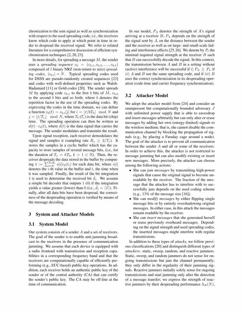
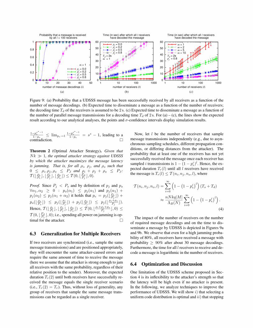
Figure 9: (a) Probability that a UDSSS message has been successfully received by all receivers as a function of thenumber of message decodings. (b) Expected time to disseminate a message as a function of the number of receivers;the decoding time Td of the receivers is assumed to be 2 s. (c) Expected time to disseminate a message as a function ofthe number of parallel message transmissions for a decoding time Td of 2 s. For (a) – (c), the lines show the expectedresult according to our analytical analyses, the points and σ-confidence intervals display simulation results.
1−ps∗−1e
1−pe≤ limpe→1
1−ps∗−1e
1−pe= s∗ − 1, leading to a
contradiction.
Theorem 2 (Optimal Attacker Strategy). Given thatNk � 1, the optimal attacker strategy against UDSSSby which the attacker maximizes the message latencyis jamming. That is, for all ρi, ρj , and ρo such that0 ≤ ρi, ρj , ρo ≤ PJ and ρi + ρj + ρo ≤ PJ :T (b ρi
Ptc, b ρj
Pjc, b ρo
Poc) ≤ T (0, bPJ
Pjc, 0).
Proof. Since Pj < Po and by definition of pj and po∀α1, α2 ≥ 0 : po(α1) ≤ pj(α1) and pj(α1) +pj(α2) ≤ pj(α1 + α2) it holds that pe = pj(b ρj
Pjc) +
po(b ρo
Poc) ≤ pj(b ρj
Pjc) + pj(b ρo
Pjc) ≤ pj(bρj+ρo
Pjc).
Hence, T (b ρi
Ptc, b ρj
Pjc, b ρo
Poc) ≤ T (0, bρi+ρj+ρo
Pjc, 0) ≤
T (0, bPJ
Pjc, 0); i.e., spending all power on jamming is op-
timal for the attacker.
6.3 Generalization for Multiple Receivers
If two receivers are synchronized (i.e., sample the samemessage transmissions) and are positioned appropriately,they will encounter the same attacker-caused errors andrequire the same amount of time to receive the message(here we assume that the attacker is strong enough to jamall receivers with the same probability, regardless of theirrelative position to the sender). Moreover, the expectedduration Tr(2) until both receivers have successfully re-ceived the message equals the single receiver scenario(i.e., Tr(2) = Tr). Thus, without loss of generality, anygroup of receivers that sample the same message trans-missions can be regarded as a single receiver.
Now, let l be the number of receivers that samplemessage transmissions independently (e.g., due to asyn-chronous sampling schedules, different propagation con-ditions, or differing distances from the attacker). Theprobability that at least one of the receivers has not yetsuccessfully received the message once each receiver hassampled i transmissions is 1− (1− pie)l. Hence, the ex-pected duration Tr(l) until all l receivers have receivedthe message is Tr(l) ≤ T (ni, nj , no, l), where
T (ni, nj , no, l) =∞∑i=0
(1−
(1− pie
)l)(Ts + Td)
≈ nNkq|M |ΛB(N)
∞∑i=0
(1−
(1− pie
)l).
(4)
The impact of the number of receivers on the numberof required message decodings and on the time to dis-seminate a message by UDSSS is depicted in Figures 9aand 9b. We observe that even for a high jamming proba-bility of 80%, all receivers have received a message withprobability ≥ 90% after about 30 message decodings.Furthermore, the time for all l receivers to receive and de-code a message is logarithmic in the number of receivers.
6.4 Optimization and DiscussionOne limitation of the UDSSS scheme proposed in Sec-tion 4 is its inflexibility to the attacker’s strength so thatthe latency will be high even if no attacker is present.In the following, we analyze techniques to improve theperformance of UDSSS. We will show i) that selecting auniform code distribution is optimal and ii) that stopping
the decoding process once a valid message was founddecreases the message latency. We also show that iii)splitting a large code set into smaller, distinct sets formultiple senders does not decrease the message latencyin general. For simplicity, we consider one receiver onlybut the results also hold for multiple receivers.
Theorem 3 (Optimal Code Distribution). Let p(ci) de-note the probability with which code sequence ci ∈ Cis selected by the sender. Without loss of generality, letfurther 1 ≥ p(c1) ≥ p(c2) ≥ . . . ≥ p(cn) ≥ 0 and∑s p(cs) = m. Selecting ci under a uniform distribu-
tion from a set of n∗ codes (i.e., p(ci) = m/n∗ for 1 ≤i ≤ n∗ and p(ci) = 0 for n∗ < i ≤ n) is optimal withrespect to the expected time Tr to receive a message.
Proof. The best strategy for the attacker is to focusher jamming on those codes that are the most likelyto be used. Given a code distribution function p(·),∑ni=1 p(ci) = m, and nj = npj(nj) as the expected
number of codes that the attacker can use in parallel toeffectively block ongoing transmissions, we get pe :=∏ni=nj+1(1 − p(ci)). It follows from Eq. 3 that Tr is
minimized if pe is minimized, that is, if p(ci) = m/n∗
for 1 ≤ i ≤ n∗ and p(ci) = 0 for n∗ < i ≤ n; the op-timal number n∗ of codes can (numerically) be derivedfrom (3) once p(ci) and nj are given.
Early Termination at the Receiver. The expectedtime to receive a message can be reduced if the receiverstops the despreading process once it verified a validmessage. Here,
Tr ≤∞∑i=1
pmie (Ts + Td) +Nkq|M |ΛB(N)
m−1∑i=0
pien
m+ 1
≈ Nkq|M |ΛB(N)
(npme
1− pme+
n
m+ 11− pme1− pe
), (5)
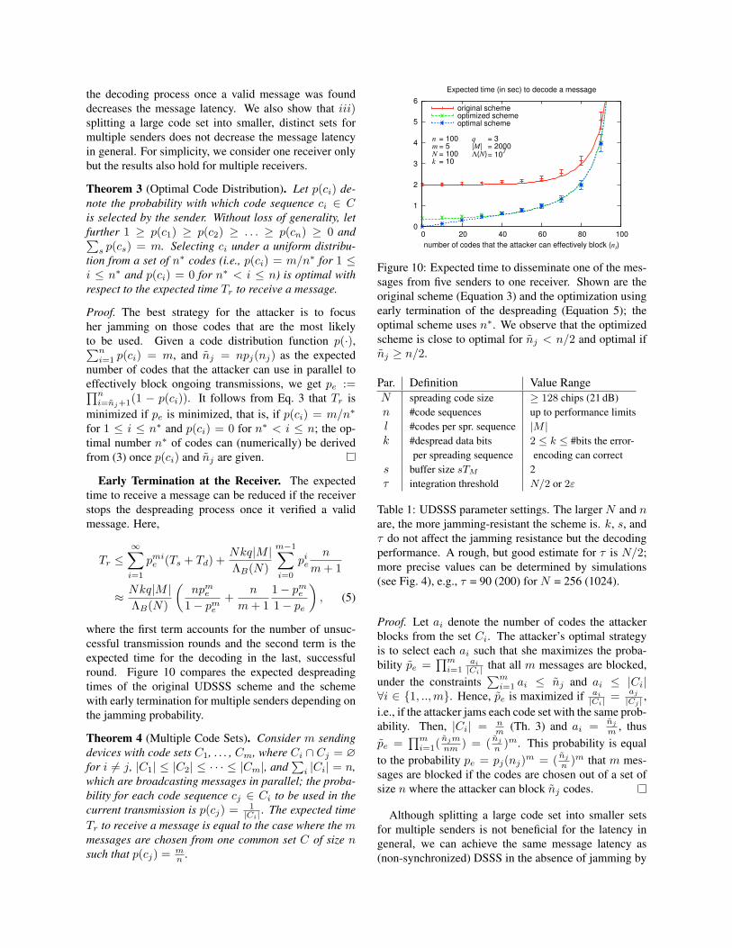
where the first term accounts for the number of unsuc-cessful transmission rounds and the second term is theexpected time for the decoding in the last, successfulround. Figure 10 compares the expected despreadingtimes of the original UDSSS scheme and the schemewith early termination for multiple senders depending onthe jamming probability.
Theorem 4 (Multiple Code Sets). Consider m sendingdevices with code sets C1, . . . , Cm, where Ci ∩ Cj = ∅for i 6= j, |C1| ≤ |C2| ≤ · · · ≤ |Cm|, and
∑i |Ci| = n,
which are broadcasting messages in parallel; the proba-bility for each code sequence cj ∈ Ci to be used in thecurrent transmission is p(cj) = 1
|Ci| . The expected timeTr to receive a message is equal to the case where the mmessages are chosen from one common set C of size nsuch that p(cj) = m
n .
0
1
2
3
4
5
6
0 20 40 60 80 100
number of codes that the attacker can effectively block (nj)
Expected time (in sec) to decode a message
nmNk
q|M|Λ(N)
= 100= 5= 100= 10
= 3= 2000= 10
7
~
original schemeoptimized schemeoptimal scheme
Figure 10: Expected time to disseminate one of the mes-sages from five senders to one receiver. Shown are theoriginal scheme (Equation 3) and the optimization usingearly termination of the despreading (Equation 5); theoptimal scheme uses n∗. We observe that the optimizedscheme is close to optimal for nj < n/2 and optimal ifnj ≥ n/2.
Par. Definition Value RangeN spreading code size ≥ 128 chips (21 dB)n #code sequences up to performance limitsl #codes per spr. sequence |M |k #despread data bits 2 ≤ k ≤ #bits the error-
per spreading sequence encoding can corrects buffer size sTM 2τ integration threshold N/2 or 2ε
Table 1: UDSSS parameter settings. The larger N and nare, the more jamming-resistant the scheme is. k, s, andτ do not affect the jamming resistance but the decodingperformance. A rough, but good estimate for τ is N/2;more precise values can be determined by simulations(see Fig. 4), e.g., τ = 90 (200) for N = 256 (1024).
Proof. Let ai denote the number of codes the attackerblocks from the set Ci. The attacker’s optimal strategyis to select each ai such that she maximizes the proba-bility pe =
∏mi=1
ai
|Ci| that all m messages are blocked,under the constraints
∑mi=1 ai ≤ nj and ai ≤ |Ci|
∀i ∈ {1, ..,m}. Hence, pe is maximized if ai
|Ci| = aj
|Cj | ,i.e., if the attacker jams each code set with the same prob-ability. Then, |Ci| = n
m (Th. 3) and ai = nj
m , thuspe =
∏mi=1( njm
nm ) = ( nj
n )m. This probability is equalto the probability pe = pj(nj)m = ( nj
n )m that m mes-sages are blocked if the codes are chosen out of a set ofsize n where the attacker can block nj codes.
Although splitting a large code set into smaller setsfor multiple senders is not beneficial for the latency ingeneral, we can achieve the same message latency as(non-synchronized) DSSS in the absence of jamming by
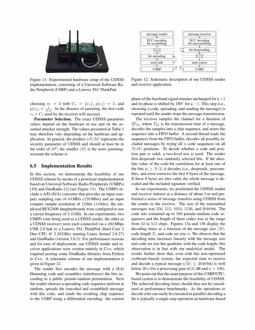
Figure 11: Experimental hardware setup of the UDSSSimplementation, consisting of a Universal Software Ra-dio Peripheral (USRP) and a Lenovo T61 ThinkPad.
choosing m = 2 with C1 = {c1}, p(c1) = 1, andp(c2) = 1
|C2| . In the absence of jamming, the first codec1 ∈ C1 used by the receiver will succeed.
Parameter Selection. The exact UDSSS parametervalues depend on the hardware in use and on the as-sumed attacker strength. The values presented in Table 1may therefore vary depending on the hardware and ap-plication. In general, the product nN |M | represents thesecurity parameter of UDSSS and should at least be inthe order of 106; the smaller |M | is the more jamming-resistant the scheme is.
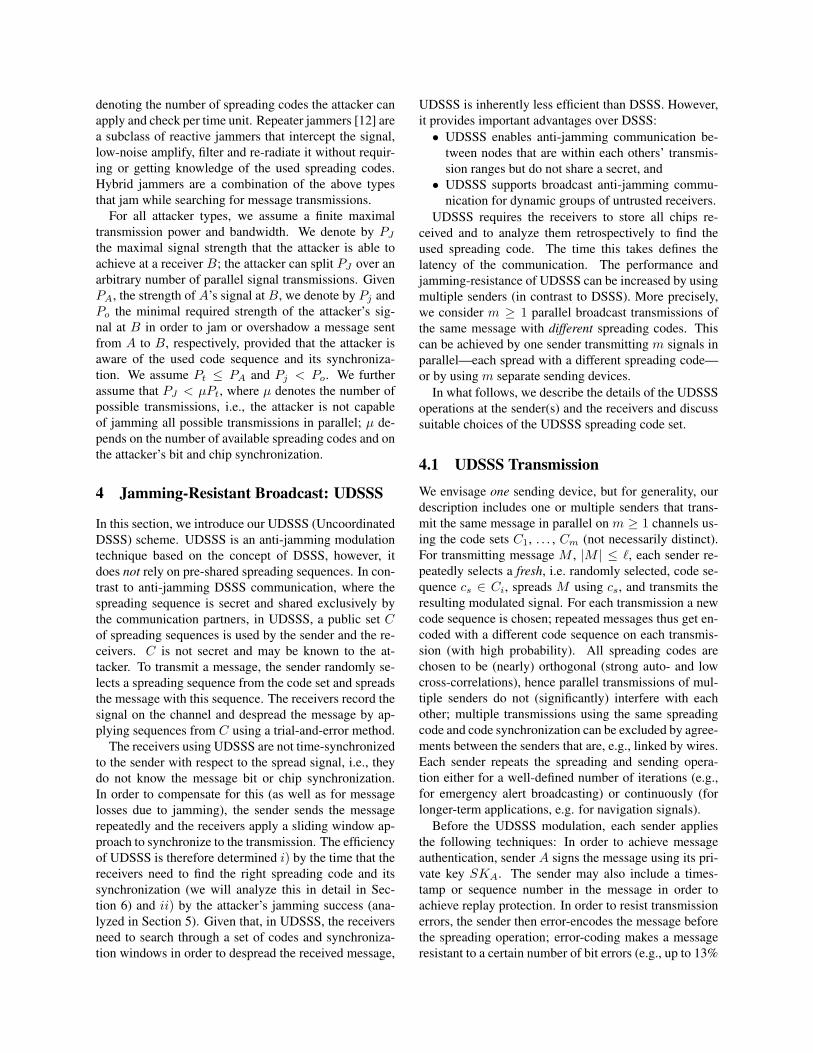
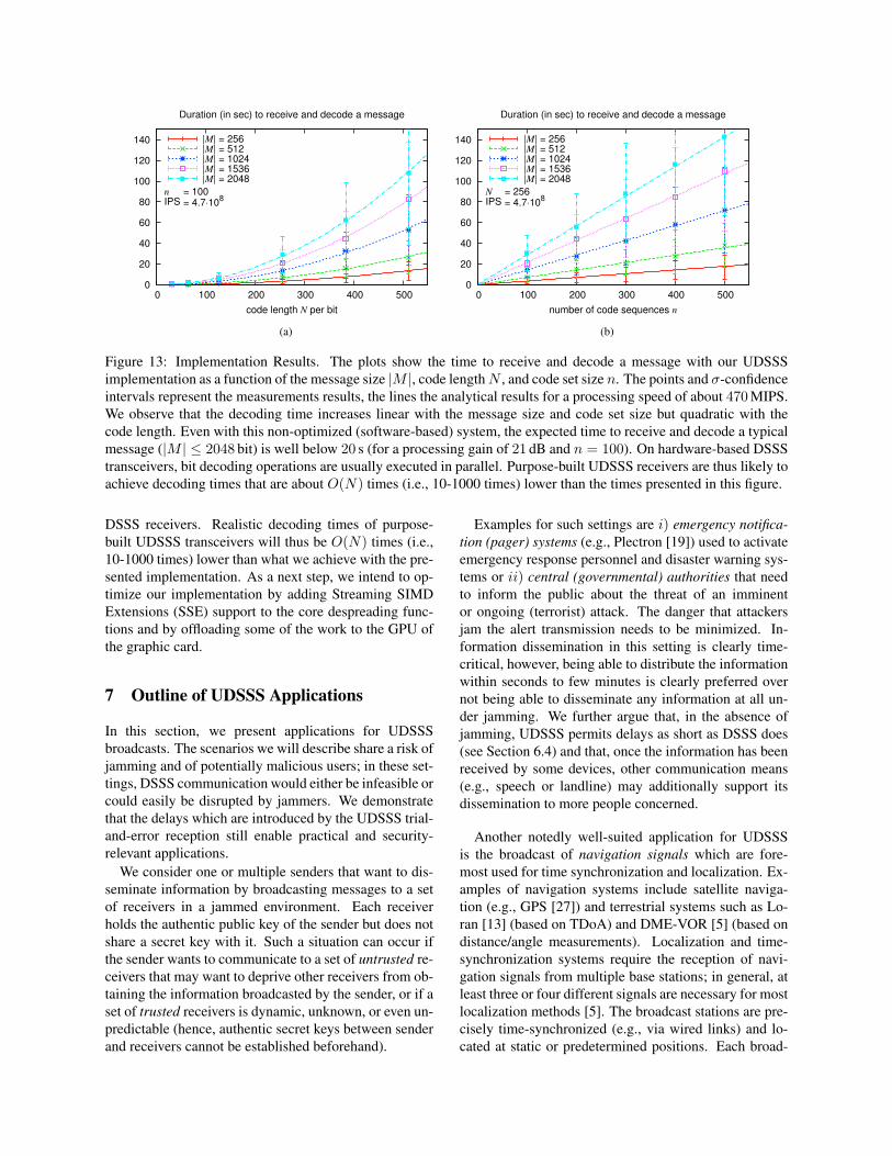
6.5 Implementation ResultsIn this section, we demonstrate the feasibility of ourUDSSS scheme by means of a prototype implementationbased on Universal Software Radio Peripherals (USRPs)[10] and GnuRadio [1] (see Figure 11). The USRPs in-clude a A/D (D/A) converter that provides an input (out-put) sampling rate of 64 Mb/s (128 Mb/s) and an input(output) sample resolution of 12 bits (14 bits); the em-ployed RFX2400 daughterboards were configured to usea carrier frequency of 2.4 GHz. In our experiments, twoUSRPs (one being used as a UDSSS sender, the other asa UDSSS receiver) were each connected via a 480 MbpsUSB 2.0 link to a Lenovo T61 ThinkPad (Intel Core 2Duo CPU @ 2.20 GHz) running Linux (kernel 2.6.27)and GnuRadio (version 3.0.3). For performance reasonsand for ease of deployment, our UDSSS sender and re-ceiver applications were written entirely in C++, whichrequired porting some GnuRadio libraries from Pythonto C++. A schematic scheme of our implementation isgiven in Figure 12.
The sender first encodes the message with a (8,4)Hamming code and scrambles (interleaves) the bits ac-cording to a public pseudo-random permutation. Nextthe sender chooses a spreading code sequence uniform atrandom, spreads the (encoded and scrambled) messagewith this code, and sends the resulting chip sequenceto the USRP using a differential encoding: the current
USRP
usrp sink
bit scrambling
usrp source
bit despreading
bit unscrambling
USRP
ECC encoding
message sender message receiver
ECC decoding
bit spreading
Figure 12: Schematic description of our UDSSS senderand receiver application.
phase of the baseband signal remains unchanged for a +1and its phase is shifted by 180◦ for a −1. This step (i.e.,choosing a code, spreading, and sending the message) isrepeated until the sender stops the message transmission.
The receiver samples the channel for a duration of2TM , where TM is the transmission time of a message,decodes the samples into a chip sequence, and stores thesequence into a FIFO buffer. A second thread reads thesequences from the FIFO buffer, decodes all possibly in-cluded messages by trying all n code sequences on allN |M | positions. To decide whether a code and posi-tion pair is valid, a two-level test is used: The senderfirst despreads two randomly selected bits. If the abso-lute value of the code-bit correlation for at least one ofthe bits is ≥ N/2, it decodes (i.e., despreads, unscram-bles, and error-corrects) the first 8 bytes of the message.If these 8 bytes are also valid, the whole message is de-coded and the included signature verified.
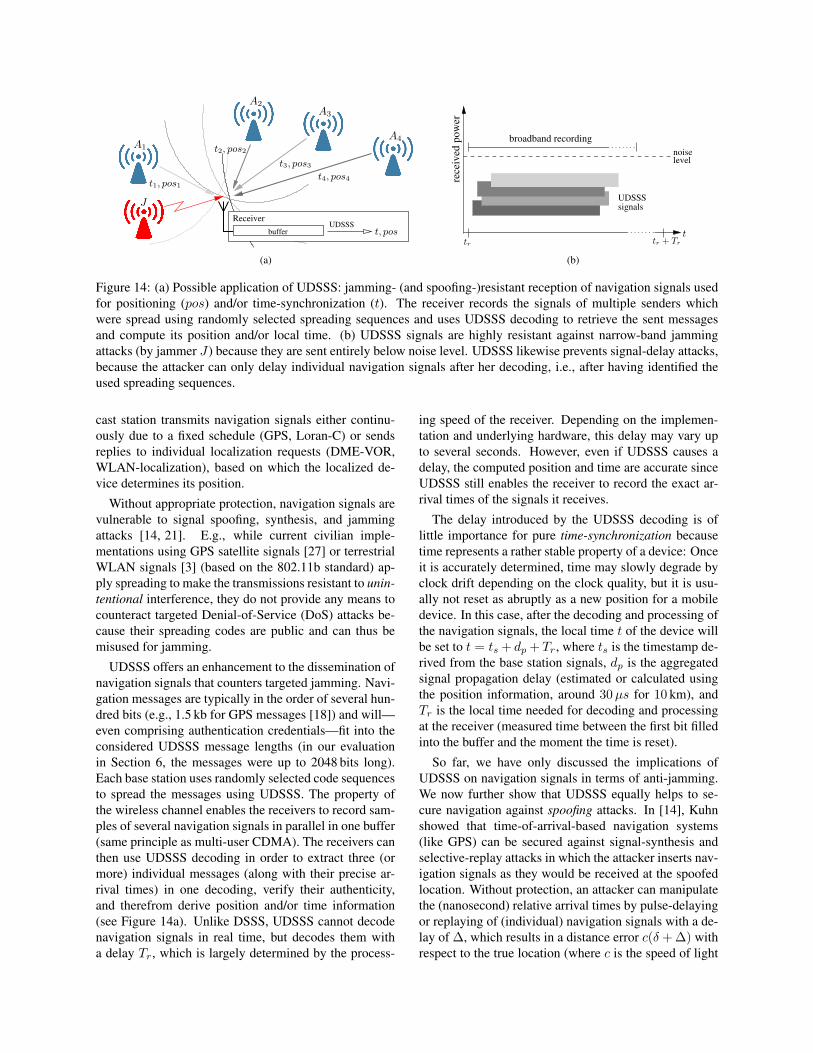
In our experiments, we positioned the UDSSS senderand receiver indoors at a distance of about 5 m and per-formed a series of message transfers using UDSSS fromthe sender to the receiver. The size of the transmittedmessages was 256, 512, 1024, 1536, and 2048 bit. Thecode sets contained up to 500 pseudo-random code se-quences and the length of these codes was in the rangefrom 32 to 512 chips. Figures 13a and 13b display thedecoding times as a function of the message size |M |,code length N , and code set size n. We observe that thedecoding time increases linearly with the message sizeand code set size but quadratic with the code length; thisobservation is in line with our analytical model. Theresults further show that, even with this non-optimized(software-based) system, the expected time to receiveand decode a typical message (|M | ≤ 2048 bit) is wellbelow 20 s (for a processing gain of 21 dB and n = 100).
We point out that the main purpose of this USRP/CPU-based system is to demonstrate the feasibility of UDSSS.The achieved decoding times should thus not be consid-ered as performance benchmarks. As the operations todecode a bit can easily be executed in parallel, decoding abit is typically a single-step operation on hardware-based
0
20
40
60
80
100
120
140
0 100 200 300 400 500
code length N per bit
Duration (in sec) to receive and decode a message
n
IPS= 100= 4.7⋅10
8
|M| = 256|M| = 512|M| = 1024|M| = 1536|M| = 2048
(a)
0
20
40
60
80
100
120
140
0 100 200 300 400 500
number of code sequences n
Duration (in sec) to receive and decode a message
N
IPS= 256= 4.7⋅10
8
|M| = 256|M| = 512|M| = 1024|M| = 1536|M| = 2048
(b)
Figure 13: Implementation Results. The plots show the time to receive and decode a message with our UDSSSimplementation as a function of the message size |M |, code lengthN , and code set size n. The points and σ-confidenceintervals represent the measurements results, the lines the analytical results for a processing speed of about 470 MIPS.We observe that the decoding time increases linear with the message size and code set size but quadratic with thecode length. Even with this non-optimized (software-based) system, the expected time to receive and decode a typicalmessage (|M | ≤ 2048 bit) is well below 20 s (for a processing gain of 21 dB and n = 100). On hardware-based DSSStransceivers, bit decoding operations are usually executed in parallel. Purpose-built UDSSS receivers are thus likely toachieve decoding times that are about O(N) times (i.e., 10-1000 times) lower than the times presented in this figure.
DSSS receivers. Realistic decoding times of purpose-built UDSSS transceivers will thus be O(N) times (i.e.,10-1000 times) lower than what we achieve with the pre-sented implementation. As a next step, we intend to op-timize our implementation by adding Streaming SIMDExtensions (SSE) support to the core despreading func-tions and by offloading some of the work to the GPU ofthe graphic card.
7 Outline of UDSSS Applications
In this section, we present applications for UDSSSbroadcasts. The scenarios we will describe share a risk ofjamming and of potentially malicious users; in these set-tings, DSSS communication would either be infeasible orcould easily be disrupted by jammers. We demonstratethat the delays which are introduced by the UDSSS trial-and-error reception still enable practical and security-relevant applications.
We consider one or multiple senders that want to dis-seminate information by broadcasting messages to a setof receivers in a jammed environment. Each receiverholds the authentic public key of the sender but does notshare a secret key with it. Such a situation can occur ifthe sender wants to communicate to a set of untrusted re-ceivers that may want to deprive other receivers from ob-taining the information broadcasted by the sender, or if aset of trusted receivers is dynamic, unknown, or even un-predictable (hence, authentic secret keys between senderand receivers cannot be established beforehand).
Examples for such settings are i) emergency notifica-tion (pager) systems (e.g., Plectron [19]) used to activateemergency response personnel and disaster warning sys-tems or ii) central (governmental) authorities that needto inform the public about the threat of an imminentor ongoing (terrorist) attack. The danger that attackersjam the alert transmission needs to be minimized. In-formation dissemination in this setting is clearly time-critical, however, being able to distribute the informationwithin seconds to few minutes is clearly preferred overnot being able to disseminate any information at all un-der jamming. We further argue that, in the absence ofjamming, UDSSS permits delays as short as DSSS does(see Section 6.4) and that, once the information has beenreceived by some devices, other communication means(e.g., speech or landline) may additionally support itsdissemination to more people concerned.
Another notedly well-suited application for UDSSSis the broadcast of navigation signals which are fore-most used for time synchronization and localization. Ex-amples of navigation systems include satellite naviga-tion (e.g., GPS [27]) and terrestrial systems such as Lo-ran [13] (based on TDoA) and DME-VOR [5] (based ondistance/angle measurements). Localization and time-synchronization systems require the reception of navi-gation signals from multiple base stations; in general, atleast three or four different signals are necessary for mostlocalization methods [5]. The broadcast stations are pre-cisely time-synchronized (e.g., via wired links) and lo-cated at static or predetermined positions. Each broad-
Receiver
buffer
UDSSS
J
A4A1
A2A3
t2, pos2
t3, pos3
t1, pos1
t, pos
t4, pos4
(a)
noiselevel
rece
ived
pow
er
broadband recording
UDSSSsignals
ttr tr + Tr
(b)
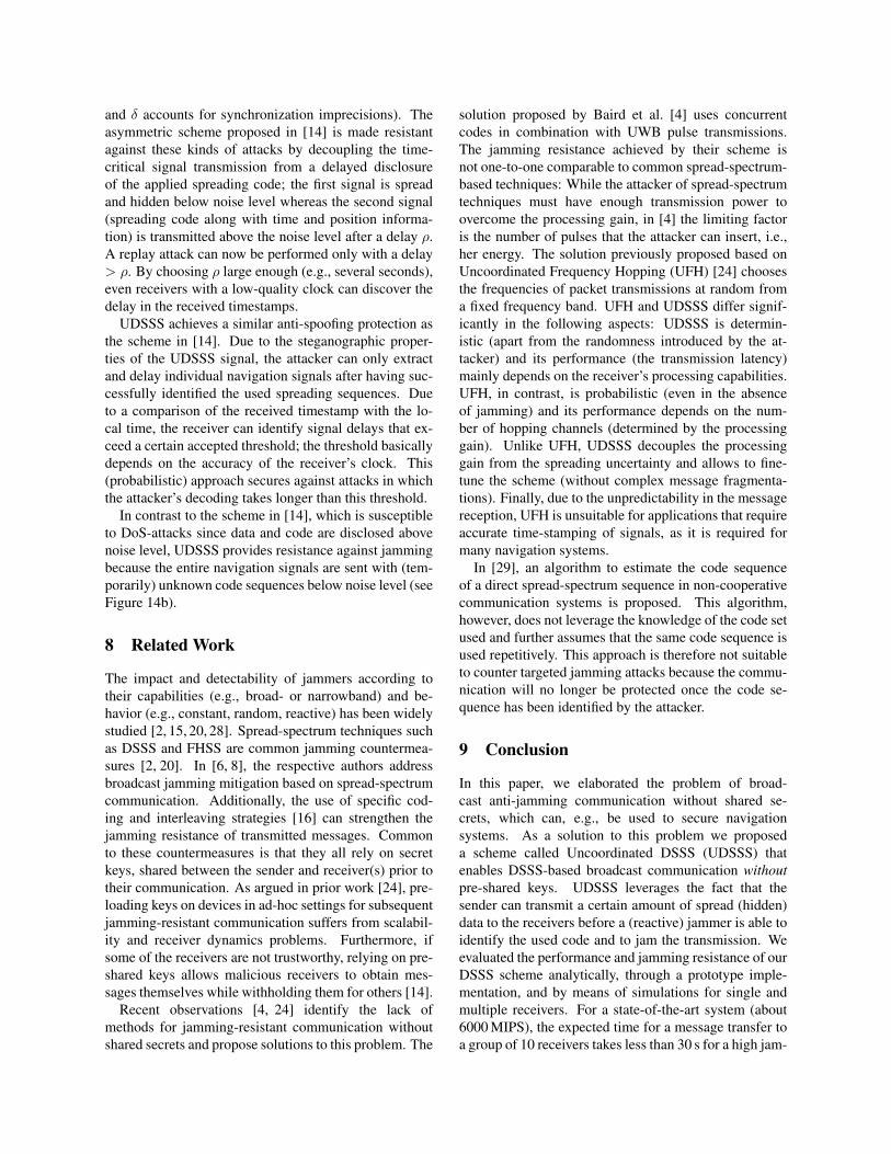
Figure 14: (a) Possible application of UDSSS: jamming- (and spoofing-)resistant reception of navigation signals usedfor positioning (pos) and/or time-synchronization (t). The receiver records the signals of multiple senders whichwere spread using randomly selected spreading sequences and uses UDSSS decoding to retrieve the sent messagesand compute its position and/or local time. (b) UDSSS signals are highly resistant against narrow-band jammingattacks (by jammer J) because they are sent entirely below noise level. UDSSS likewise prevents signal-delay attacks,because the attacker can only delay individual navigation signals after her decoding, i.e., after having identified theused spreading sequences.
cast station transmits navigation signals either continu-ously due to a fixed schedule (GPS, Loran-C) or sendsreplies to individual localization requests (DME-VOR,WLAN-localization), based on which the localized de-vice determines its position.
Without appropriate protection, navigation signals arevulnerable to signal spoofing, synthesis, and jammingattacks [14, 21]. E.g., while current civilian imple-mentations using GPS satellite signals [27] or terrestrialWLAN signals [3] (based on the 802.11b standard) ap-ply spreading to make the transmissions resistant to unin-tentional interference, they do not provide any means tocounteract targeted Denial-of-Service (DoS) attacks be-cause their spreading codes are public and can thus bemisused for jamming.
UDSSS offers an enhancement to the dissemination ofnavigation signals that counters targeted jamming. Navi-gation messages are typically in the order of several hun-dred bits (e.g., 1.5 kb for GPS messages [18]) and will—even comprising authentication credentials—fit into theconsidered UDSSS message lengths (in our evaluationin Section 6, the messages were up to 2048 bits long).Each base station uses randomly selected code sequencesto spread the messages using UDSSS. The property ofthe wireless channel enables the receivers to record sam-ples of several navigation signals in parallel in one buffer(same principle as multi-user CDMA). The receivers canthen use UDSSS decoding in order to extract three (ormore) individual messages (along with their precise ar-rival times) in one decoding, verify their authenticity,and therefrom derive position and/or time information(see Figure 14a). Unlike DSSS, UDSSS cannot decodenavigation signals in real time, but decodes them witha delay Tr, which is largely determined by the process-
ing speed of the receiver. Depending on the implemen-tation and underlying hardware, this delay may vary upto several seconds. However, even if UDSSS causes adelay, the computed position and time are accurate sinceUDSSS still enables the receiver to record the exact ar-rival times of the signals it receives.
The delay introduced by the UDSSS decoding is oflittle importance for pure time-synchronization becausetime represents a rather stable property of a device: Onceit is accurately determined, time may slowly degrade byclock drift depending on the clock quality, but it is usu-ally not reset as abruptly as a new position for a mobiledevice. In this case, after the decoding and processing ofthe navigation signals, the local time t of the device willbe set to t = ts + dp + Tr, where ts is the timestamp de-rived from the base station signals, dp is the aggregatedsignal propagation delay (estimated or calculated usingthe position information, around 30µs for 10 km), andTr is the local time needed for decoding and processingat the receiver (measured time between the first bit filledinto the buffer and the moment the time is reset).
So far, we have only discussed the implications ofUDSSS on navigation signals in terms of anti-jamming.We now further show that UDSSS equally helps to se-cure navigation against spoofing attacks. In [14], Kuhnshowed that time-of-arrival-based navigation systems(like GPS) can be secured against signal-synthesis andselective-replay attacks in which the attacker inserts nav-igation signals as they would be received at the spoofedlocation. Without protection, an attacker can manipulatethe (nanosecond) relative arrival times by pulse-delayingor replaying of (individual) navigation signals with a de-lay of ∆, which results in a distance error c(δ + ∆) withrespect to the true location (where c is the speed of light
and δ accounts for synchronization imprecisions). Theasymmetric scheme proposed in [14] is made resistantagainst these kinds of attacks by decoupling the time-critical signal transmission from a delayed disclosureof the applied spreading code; the first signal is spreadand hidden below noise level whereas the second signal(spreading code along with time and position informa-tion) is transmitted above the noise level after a delay ρ.A replay attack can now be performed only with a delay> ρ. By choosing ρ large enough (e.g., several seconds),even receivers with a low-quality clock can discover thedelay in the received timestamps.
UDSSS achieves a similar anti-spoofing protection asthe scheme in [14]. Due to the steganographic proper-ties of the UDSSS signal, the attacker can only extractand delay individual navigation signals after having suc-cessfully identified the used spreading sequences. Dueto a comparison of the received timestamp with the lo-cal time, the receiver can identify signal delays that ex-ceed a certain accepted threshold; the threshold basicallydepends on the accuracy of the receiver’s clock. This(probabilistic) approach secures against attacks in whichthe attacker’s decoding takes longer than this threshold.
In contrast to the scheme in [14], which is susceptibleto DoS-attacks since data and code are disclosed abovenoise level, UDSSS provides resistance against jammingbecause the entire navigation signals are sent with (tem-porarily) unknown code sequences below noise level (seeFigure 14b).
8 Related Work
The impact and detectability of jammers according totheir capabilities (e.g., broad- or narrowband) and be-havior (e.g., constant, random, reactive) has been widelystudied [2, 15, 20, 28]. Spread-spectrum techniques suchas DSSS and FHSS are common jamming countermea-sures [2, 20]. In [6, 8], the respective authors addressbroadcast jamming mitigation based on spread-spectrumcommunication. Additionally, the use of specific cod-ing and interleaving strategies [16] can strengthen thejamming resistance of transmitted messages. Commonto these countermeasures is that they all rely on secretkeys, shared between the sender and receiver(s) prior totheir communication. As argued in prior work [24], pre-loading keys on devices in ad-hoc settings for subsequentjamming-resistant communication suffers from scalabil-ity and receiver dynamics problems. Furthermore, ifsome of the receivers are not trustworthy, relying on pre-shared keys allows malicious receivers to obtain mes-sages themselves while withholding them for others [14].
Recent observations [4, 24] identify the lack ofmethods for jamming-resistant communication withoutshared secrets and propose solutions to this problem. The
solution proposed by Baird et al. [4] uses concurrentcodes in combination with UWB pulse transmissions.The jamming resistance achieved by their scheme isnot one-to-one comparable to common spread-spectrum-based techniques: While the attacker of spread-spectrumtechniques must have enough transmission power toovercome the processing gain, in [4] the limiting factoris the number of pulses that the attacker can insert, i.e.,her energy. The solution previously proposed based onUncoordinated Frequency Hopping (UFH) [24] choosesthe frequencies of packet transmissions at random froma fixed frequency band. UFH and UDSSS differ signif-icantly in the following aspects: UDSSS is determin-istic (apart from the randomness introduced by the at-tacker) and its performance (the transmission latency)mainly depends on the receiver’s processing capabilities.UFH, in contrast, is probabilistic (even in the absenceof jamming) and its performance depends on the num-ber of hopping channels (determined by the processinggain). Unlike UFH, UDSSS decouples the processinggain from the spreading uncertainty and allows to fine-tune the scheme (without complex message fragmenta-tions). Finally, due to the unpredictability in the messagereception, UFH is unsuitable for applications that requireaccurate time-stamping of signals, as it is required formany navigation systems.
In [29], an algorithm to estimate the code sequenceof a direct spread-spectrum sequence in non-cooperativecommunication systems is proposed. This algorithm,however, does not leverage the knowledge of the code setused and further assumes that the same code sequence isused repetitively. This approach is therefore not suitableto counter targeted jamming attacks because the commu-nication will no longer be protected once the code se-quence has been identified by the attacker.
9 Conclusion
In this paper, we elaborated the problem of broad-cast anti-jamming communication without shared se-crets, which can, e.g., be used to secure navigationsystems. As a solution to this problem we proposeda scheme called Uncoordinated DSSS (UDSSS) thatenables DSSS-based broadcast communication withoutpre-shared keys. UDSSS leverages the fact that thesender can transmit a certain amount of spread (hidden)data to the receivers before a (reactive) jammer is able toidentify the used code and to jam the transmission. Weevaluated the performance and jamming resistance of ourDSSS scheme analytically, through a prototype imple-mentation, and by means of simulations for single andmultiple receivers. For a state-of-the-art system (about6000 MIPS), the expected time for a message transfer toa group of 10 receivers takes less than 30 s for a high jam-
ming probability of 80%. We accent that this time is rea-sonably short, given that with common (key-dependent)anti-jamming techniques the devices would not be ableto broadcast jamming-resistant messages at all.
10 Acknowledgments
We are grateful to Fabian Monrose for his valuable input.We also thank the anonymous reviewers for their sugges-tions. The work presented in this paper was partially sup-ported by the Swiss National Science Foundation underGrant 200021-116444.
References[1] GNU Radio Software. http://gnuradio.org/trac.
[2] ADAMY, D. A first course in electronic warfare. Artech House,2001.
[3] BAHL, P., AND PADMANABHAN, V. N. RADAR: An In-Building RF-Based User Location and Tracking System. In Pro-ceedings of the IEEE Conference on Computer Communications(InfoCom) (2000), vol. 2, pp. 775–784.
[4] BAIRD, L. C., BAHN, W. L., COLLINS, M. D., CARLISLE,M. C., AND BUTLER, S. C. Keyless Jam Resistance. In Pro-ceedings of the IEEE Information Assurance and Security Work-shop (June 2007), pp. 143–150.
[5] BENSKY, A. Wireless Positioning Technologies and Applica-tions. GNSS Technology and Applications Series. Artech House,2008.
[6] CHIANG, J., AND HU, Y.-C. Dynamic jamming mitigation forwireless broadcast networks. In Proceedings of the IEEE Confer-ence on Computer Communications (InfoCom) (2008).
[7] CHUNG, F. R. K., SALEHI, J. A., AND WEI, V. K. Optical or-thogonal codes: Design, analysis and applications. IEEE Trans-actions on Information Theory 35, 3 (1989), 595–604.
[8] DESMEDT, Y., SAFAVI-NAINI, R., WANG, H., CHARNES, C.,AND PIEPRZYK, J. Broadcast anti-jamming systems. In Proceed-ings of the IEEE International Conference on Networks (ICON)(1999).
[9] DILLARD, R. A., AND DILLARD, G. M. Detectability ofSpread-spectrum Signals. Artech House Publishers, 1989.
[10] ETTUS. USRP – Universal Software Radio Peripheral.http://www.ettus.com.
[11] GOLDSMITH, A. Wireless communications. Cambridge Univer-sity Press, 2005.
[12] HANG, W., ZANJI, W., AND JINGBO, G. Performance of DSSSagainst repeater jamming. In Proceedings of the IEEE Interna-tional Conference on Electronics, Circuits, and Systems (ICECS)(2006), pp. 858–861.
[13] INTERNATIONAL LORAN ASSOCIATION. LORAN: LOngRange Aid to Navigation. http://www.loran.org.
[14] KUHN, M. G. An asymmetric security mechanism for naviga-tion signals. In Proceedings of the Information Hiding Workshop(2004), pp. 239–252.
[15] LI, M., KOUTSOPOULOS, I., AND POOVENDRAN, R. Optimaljamming attacks and network defense policies in wireless sensornetworks. In Proceedings of the IEEE Conference on ComputerCommunications (InfoCom) (2007), pp. 1307–1315.
[16] LIN, G., AND NOUBIR, G. On link layer denial of service in datawireless LANs: Research articles. Wireless Communications &Mobile Computing 5, 3 (2005), 273–284.
[17] NATARAJAN, B., DAS, S., AND STEVENS, D. An evolutionaryapproach to designing complex spreading codes for DS-CDMA.IEEE Transactions on Wireless Communications 4, 5 (2005),2051–2056.
[18] NAVSTAR SPACE AND MISSILE SYSTEMS CENTER. NavstarGlobal Positioning System: Interface Specification IS-GPS-200.http://www.losangeles.af.mil, 2006.
[19] PARNASS, B. Plectron R-700 Monitor Receivers. MonitoringTimes Magazine (October 1999).
[20] POISEL, R. A. Modern Communications Jamming Principlesand Techniques. Artech House Publishers, 2006.
[21] RASMUSSEN, K. B., CAPKUN, S., AND CAGALJ, M. SecNav:secure broadcast localization and time synchronization in wire-less networks. In Proceedings of the ACM International Confer-ence on Mobile Computing and Networking (MobiCom) (2007),pp. 310–313.
[22] SARWATE, D. V., AND PURSLEY, M. B. Crosscorrelation prop-erties of pseudo-random and related sequences. In Proceedingsof the IEEE (May 1980), vol. 68, pp. 593–619.
[23] SKLAR, B. Digital communications: fundamentals and applica-tions. Prentice-Hall, 2001.
[24] STRASSER, M., POPPER, C., CAPKUN, S., AND CAGALJ, M.Jamming-resistant key establishment using uncoordinated fre-quency hopping. In Proceedings of the IEEE Symposium on Se-curity and Privacy (2008), pp. 64–78.
[25] TJHUNG, T. T., AND CHAI, C. C. Multitone Jamming ofFH/BFSK in Rician Channels. IEEE Transactions on Commu-nications 47, 7 (July 1999).
[26] TSE, D., AND VISWANATH, P. Fundamentals of Wireless Com-munication. Cambridge University Press, 2005.
[27] U.S. GOVERNMENT. Global positioning system.http://www.gps.gov, March 2008.
[28] XU, W., TRAPPE, W., ZHANG, Y., AND WOOD, T. The feasi-bility of launching and detecting jamming attacks in wireless net-works. In Proceedings of the ACM International Symposium onMobile Ad Hoc Networking and Computing (MobiHoc) (2005),pp. 46–57.
[29] ZHAN, Y., CAO, Z., AND LU, J. Spread-spectrum sequenceestimation for DSSS signal in non-cooperative communicationsystems. In IEE Proceedings Communications Magazine, IEEE(Aug. 2005).
Notes1Gold- and Kasami-codes have the same correlation properties and
both approach the Welch lower bound in their cross-correlation val-ues. However, Gold- and Kasami-codes differ in the number of codesthat can be created. While the number of Gold-codes of length N thatcan be constructed is N + 2 (e.g., 257 for N = 255 and 1025 forN = 1023), the number of Kasami-codes of length N (in the largeset) is considerably higher: ≈ 2
32 log2(N+1) (e.g., 4112 for N = 255
and 32800 for N = 1023) [17]. Kasami-codes are therefore more ap-propriate for UDSSS, although even Kasami codes may have to reoccurin multiple code sequences (if n` > 2
32 log2(N+1)).
2∀ci,j ∈ C, ∀t ∈ {0, 1, . . . , N − 1}, and a small ε � N , theauto-correlation of the codes is
∑N−1
q=0ci,j [q]ci,j [q + t mod N ] ≈
N if t = 0 and ≤ ε else, where ci,j [q] ∈ {−1, +1} denotes theq-th value of the spreading code ci,j and ε indicates the quality of theauto-correlation (the less the better). Similarly, ∀ci,j , ci′,j′ ∈ C, t ∈{0, 1, . . . , N − 1} the cross-correlation is
∑N−1
q=0ci,j [q]ci′,j′ [q +
t mod N ] ≤ ε.