january 2015 rosemount 3300 series - automation … rosemount documen… · january 2015 rosemount...
TRANSCRIPT

Reference Manual00809-0100-4811, Rev DA
January 2015
Rosemount 3300 SeriesGuided Wave Radar Level and Interface Transmitters

iii
Reference Manual 00809-0100-4811, Rev DA January 2015
Rosemount 3300 Series
Guided Wave Radar Level and Interface Transmitters
Rosemount 3300 Series Guided Wave Radar Level and Interface Transmitters may be protected by one or more U.S. Patents pending and foreign patents pending.
Read this manual before working with the product. For personal and system safety, and for optimum product performance, make sure you thoroughly understand the contents before installing, using, or maintaining this product.
Within the United States, Emerson Process Management has two toll-free assistance numbers.
Customer Central: 1-800-999-9307 (7:00 a.m. to 7:00 p.m. CST)Technical support, quoting, and order-related questions.
North-American Response Center:
Equipment service needs.
1-800-654-7768 (24 hours a day – Includes Canada)
For equipment service or support needs outside the United States, contact your local Emerson Process Management representative.
The products described in this document are NOT designed for nuclear-qualified applications.
Using non-nuclear qualified products in applications that require nuclear-qualified hardware or products may cause inaccurate readings.
For information on Rosemount nuclear-qualified products, contact your local Emerson Process Management Sales Representative.
This product is designed to meet FCC and R&TTE requirements for a non-intentional radiator. It does not require any licensing whatsoever and has no tank restrictions associated with telecommunications issues.
This device complies with part 15 of the FCC rules. Operation is subject to the following two conditions: (1) This device may not cause harmful interference, and (2) this device must accept any interference received, including interference that may cause undesired operation.

iv
Reference Manual00809-0100-4811, Rev DAJanuary 2015
Reference Manual 00809-0100-4811, Rev DA
ContentsJanuary 2015
Contents
1Section 1: Introduction1.1 Safety messages . . . . . . . . . . . . . . . . . . . . . . . . . . . . . . . . . . . . . . . . . . . . . . . . . . . . . . 1
1.2 Manual overview . . . . . . . . . . . . . . . . . . . . . . . . . . . . . . . . . . . . . . . . . . . . . . . . . . . . . . 4
1.3 Service support . . . . . . . . . . . . . . . . . . . . . . . . . . . . . . . . . . . . . . . . . . . . . . . . . . . . . . . 5
1.4 Product recycling/disposal . . . . . . . . . . . . . . . . . . . . . . . . . . . . . . . . . . . . . . . . . . . . . 5
2Section 2: Transmitter Overview2.1 Theory of operation . . . . . . . . . . . . . . . . . . . . . . . . . . . . . . . . . . . . . . . . . . . . . . . . . . . 7
2.2 Application examples . . . . . . . . . . . . . . . . . . . . . . . . . . . . . . . . . . . . . . . . . . . . . . . . . 8
2.3 System architecture . . . . . . . . . . . . . . . . . . . . . . . . . . . . . . . . . . . . . . . . . . . . . . . . . . 10
2.4 Process characteristics . . . . . . . . . . . . . . . . . . . . . . . . . . . . . . . . . . . . . . . . . . . . . . . . 11
2.4.1 Coating . . . . . . . . . . . . . . . . . . . . . . . . . . . . . . . . . . . . . . . . . . . . . . . . . . . . . . . 11
2.4.2 Bridging . . . . . . . . . . . . . . . . . . . . . . . . . . . . . . . . . . . . . . . . . . . . . . . . . . . . . . . 11
2.4.3 Foam . . . . . . . . . . . . . . . . . . . . . . . . . . . . . . . . . . . . . . . . . . . . . . . . . . . . . . . . . 11
2.4.4 Vapor . . . . . . . . . . . . . . . . . . . . . . . . . . . . . . . . . . . . . . . . . . . . . . . . . . . . . . . . . 11
2.4.5 Measuring range . . . . . . . . . . . . . . . . . . . . . . . . . . . . . . . . . . . . . . . . . . . . . . . 11
2.4.6 Interface . . . . . . . . . . . . . . . . . . . . . . . . . . . . . . . . . . . . . . . . . . . . . . . . . . . . . . 12
2.5 Vessel characteristics . . . . . . . . . . . . . . . . . . . . . . . . . . . . . . . . . . . . . . . . . . . . . . . . . 13
2.5.1 Heating coils, agitators . . . . . . . . . . . . . . . . . . . . . . . . . . . . . . . . . . . . . . . . . 13
2.5.2 Tank shape . . . . . . . . . . . . . . . . . . . . . . . . . . . . . . . . . . . . . . . . . . . . . . . . . . . . 14
2.6 Components of the transmitter . . . . . . . . . . . . . . . . . . . . . . . . . . . . . . . . . . . . . . . . 14
2.7 Probe selection guide . . . . . . . . . . . . . . . . . . . . . . . . . . . . . . . . . . . . . . . . . . . . . . . . 15
2.7.1 Transition zones . . . . . . . . . . . . . . . . . . . . . . . . . . . . . . . . . . . . . . . . . . . . . . . 16
3Section 3: Installation3.1 Safety messages . . . . . . . . . . . . . . . . . . . . . . . . . . . . . . . . . . . . . . . . . . . . . . . . . . . . . 17
3.2 Installation procedure . . . . . . . . . . . . . . . . . . . . . . . . . . . . . . . . . . . . . . . . . . . . . . . . 19
3.3 Before you install . . . . . . . . . . . . . . . . . . . . . . . . . . . . . . . . . . . . . . . . . . . . . . . . . . . . 20
3.3.1 Alarm and write protection switches . . . . . . . . . . . . . . . . . . . . . . . . . . . . . . 20
3.4 Mounting considerations . . . . . . . . . . . . . . . . . . . . . . . . . . . . . . . . . . . . . . . . . . . . . 22
3.4.1 Process connection . . . . . . . . . . . . . . . . . . . . . . . . . . . . . . . . . . . . . . . . . . . . . 22
3.4.2 Installation of single lead probes in non-metallic tanks . . . . . . . . . . . . . . 24
3.4.3 Mounting in still pipes/bypass pipes . . . . . . . . . . . . . . . . . . . . . . . . . . . . . . 24
3.4.4 Free space . . . . . . . . . . . . . . . . . . . . . . . . . . . . . . . . . . . . . . . . . . . . . . . . . . . . . 26
3.4.5 Recommended mounting position . . . . . . . . . . . . . . . . . . . . . . . . . . . . . . . 27
3.4.6 Insulated tanks . . . . . . . . . . . . . . . . . . . . . . . . . . . . . . . . . . . . . . . . . . . . . . . . 28
vContents
Reference Manual00809-0100-4811, Rev DA
ContentsJanuary 2015
3.5 Mechanical installation . . . . . . . . . . . . . . . . . . . . . . . . . . . . . . . . . . . . . . . . . . . . . . . 29
3.5.1 Tank connection with flange . . . . . . . . . . . . . . . . . . . . . . . . . . . . . . . . . . . . . 29
3.5.2 Tank connection with loose flange (“plate design”) . . . . . . . . . . . . . . . . . 30
3.5.3 Threaded tank connection . . . . . . . . . . . . . . . . . . . . . . . . . . . . . . . . . . . . . . 31
3.5.4 Shortening the probe . . . . . . . . . . . . . . . . . . . . . . . . . . . . . . . . . . . . . . . . . . . 33
3.5.5 Using a segmented probe . . . . . . . . . . . . . . . . . . . . . . . . . . . . . . . . . . . . . . . 36
3.5.6 Adjusting the probe length . . . . . . . . . . . . . . . . . . . . . . . . . . . . . . . . . . . . . . 44
3.5.7 Anchoring . . . . . . . . . . . . . . . . . . . . . . . . . . . . . . . . . . . . . . . . . . . . . . . . . . . . . 47
3.5.8 Mounting a centering disc for pipe installations . . . . . . . . . . . . . . . . . . . . 49
3.6 Electrical installation . . . . . . . . . . . . . . . . . . . . . . . . . . . . . . . . . . . . . . . . . . . . . . . . . 52
3.6.1 Cable/conduit entries . . . . . . . . . . . . . . . . . . . . . . . . . . . . . . . . . . . . . . . . . . . 52
3.6.2 Grounding . . . . . . . . . . . . . . . . . . . . . . . . . . . . . . . . . . . . . . . . . . . . . . . . . . . . 52
3.6.3 Cable selection . . . . . . . . . . . . . . . . . . . . . . . . . . . . . . . . . . . . . . . . . . . . . . . . 53
3.6.4 Hazardous areas . . . . . . . . . . . . . . . . . . . . . . . . . . . . . . . . . . . . . . . . . . . . . . . 53
3.6.5 HART . . . . . . . . . . . . . . . . . . . . . . . . . . . . . . . . . . . . . . . . . . . . . . . . . . . . . . . . . 53
3.6.6 HART to Modbus Converter (HMC) . . . . . . . . . . . . . . . . . . . . . . . . . . . . . . . 57
3.7 Optional devices . . . . . . . . . . . . . . . . . . . . . . . . . . . . . . . . . . . . . . . . . . . . . . . . . . . . . 58
3.7.1 Tri-Loop™ . . . . . . . . . . . . . . . . . . . . . . . . . . . . . . . . . . . . . . . . . . . . . . . . . . . . . 58
3.7.2 Using more than one transmitter on the bus . . . . . . . . . . . . . . . . . . . . . . . 59
3.7.3 751 Field Signal Indicator . . . . . . . . . . . . . . . . . . . . . . . . . . . . . . . . . . . . . . . 60
4Section 4: Basic Configuration/Start-Up4.1 Safety messages . . . . . . . . . . . . . . . . . . . . . . . . . . . . . . . . . . . . . . . . . . . . . . . . . . . . . 61
4.2 Configuration parameters . . . . . . . . . . . . . . . . . . . . . . . . . . . . . . . . . . . . . . . . . . . . 62
4.2.1 Basic configuration . . . . . . . . . . . . . . . . . . . . . . . . . . . . . . . . . . . . . . . . . . . . . 62
4.2.2 Volume configuration . . . . . . . . . . . . . . . . . . . . . . . . . . . . . . . . . . . . . . . . . . 64
4.3 Configuration using a Field Communicator . . . . . . . . . . . . . . . . . . . . . . . . . . . . . . 67
4.4 Basic configuration . . . . . . . . . . . . . . . . . . . . . . . . . . . . . . . . . . . . . . . . . . . . . . . . . . . 69
4.4.1 Transmitter variables . . . . . . . . . . . . . . . . . . . . . . . . . . . . . . . . . . . . . . . . . . . 69
4.4.2 Measurement units . . . . . . . . . . . . . . . . . . . . . . . . . . . . . . . . . . . . . . . . . . . . . 70
4.4.3 Reference gauge height . . . . . . . . . . . . . . . . . . . . . . . . . . . . . . . . . . . . . . . . . 70
4.4.4 Probe length . . . . . . . . . . . . . . . . . . . . . . . . . . . . . . . . . . . . . . . . . . . . . . . . . . . 70
4.4.5 Probe type . . . . . . . . . . . . . . . . . . . . . . . . . . . . . . . . . . . . . . . . . . . . . . . . . . . . 70
4.4.6 Product dielectric . . . . . . . . . . . . . . . . . . . . . . . . . . . . . . . . . . . . . . . . . . . . . . 71
4.4.7 Vapor dielectric . . . . . . . . . . . . . . . . . . . . . . . . . . . . . . . . . . . . . . . . . . . . . . . . 71
4.4.8 Measurement mode . . . . . . . . . . . . . . . . . . . . . . . . . . . . . . . . . . . . . . . . . . . . 71
4.4.9 Probe angle . . . . . . . . . . . . . . . . . . . . . . . . . . . . . . . . . . . . . . . . . . . . . . . . . . . 72
4.4.10 Maximum upper product thickness . . . . . . . . . . . . . . . . . . . . . . . . . . . . . . 72
vi Contents
Reference Manual 00809-0100-4811, Rev DA
ContentsJanuary 2015
4.4.11 Damping . . . . . . . . . . . . . . . . . . . . . . . . . . . . . . . . . . . . . . . . . . . . . . . . . . . . . 72
4.4.12 Display panel . . . . . . . . . . . . . . . . . . . . . . . . . . . . . . . . . . . . . . . . . . . . . . . . . . 72
4.4.13 4 and 20 mA points . . . . . . . . . . . . . . . . . . . . . . . . . . . . . . . . . . . . . . . . . . . . 73
4.5 Volume configuration . . . . . . . . . . . . . . . . . . . . . . . . . . . . . . . . . . . . . . . . . . . . . . . . 74
4.5.1 Transmitter variables . . . . . . . . . . . . . . . . . . . . . . . . . . . . . . . . . . . . . . . . . . . 74
4.5.2 Volume units . . . . . . . . . . . . . . . . . . . . . . . . . . . . . . . . . . . . . . . . . . . . . . . . . . 74
4.5.3 Tank type . . . . . . . . . . . . . . . . . . . . . . . . . . . . . . . . . . . . . . . . . . . . . . . . . . . . . 74
4.5.4 Tank dimensions . . . . . . . . . . . . . . . . . . . . . . . . . . . . . . . . . . . . . . . . . . . . . . . 74
4.5.5 Strapping table . . . . . . . . . . . . . . . . . . . . . . . . . . . . . . . . . . . . . . . . . . . . . . . . 74
4.6 Configuration using the Radar Configuration Tool . . . . . . . . . . . . . . . . . . . . . . . 75
4.6.1 Installing the RCT software . . . . . . . . . . . . . . . . . . . . . . . . . . . . . . . . . . . . . . 75
4.6.2 Specifying the COM port . . . . . . . . . . . . . . . . . . . . . . . . . . . . . . . . . . . . . . . . 75
4.6.3 Help in RCT . . . . . . . . . . . . . . . . . . . . . . . . . . . . . . . . . . . . . . . . . . . . . . . . . . . . 76
4.6.4 Using the Setup Wizard . . . . . . . . . . . . . . . . . . . . . . . . . . . . . . . . . . . . . . . . . 76
4.6.5 Using the Setup function . . . . . . . . . . . . . . . . . . . . . . . . . . . . . . . . . . . . . . . . 78
4.6.6 Setup - Info . . . . . . . . . . . . . . . . . . . . . . . . . . . . . . . . . . . . . . . . . . . . . . . . . . . . 79
4.6.7 Setup - Basics . . . . . . . . . . . . . . . . . . . . . . . . . . . . . . . . . . . . . . . . . . . . . . . . . . 79
4.6.8 Setup - Output . . . . . . . . . . . . . . . . . . . . . . . . . . . . . . . . . . . . . . . . . . . . . . . . . 80
4.6.9 Setup - Probe . . . . . . . . . . . . . . . . . . . . . . . . . . . . . . . . . . . . . . . . . . . . . . . . . . 81
4.6.10 Setup - Geometry . . . . . . . . . . . . . . . . . . . . . . . . . . . . . . . . . . . . . . . . . . . . . . 82
4.6.11 Setup - Volume . . . . . . . . . . . . . . . . . . . . . . . . . . . . . . . . . . . . . . . . . . . . . . . . 84
4.6.12 Setup - Display . . . . . . . . . . . . . . . . . . . . . . . . . . . . . . . . . . . . . . . . . . . . . . . . 85
4.6.13 Setup - Signal Quality Metrics . . . . . . . . . . . . . . . . . . . . . . . . . . . . . . . . . . . 86
4.7 Special functions . . . . . . . . . . . . . . . . . . . . . . . . . . . . . . . . . . . . . . . . . . . . . . . . . . . . . 87
4.7.1 Tri-Loop™ . . . . . . . . . . . . . . . . . . . . . . . . . . . . . . . . . . . . . . . . . . . . . . . . . . . . . 87
5Section 5: Operation5.1 Display functionality . . . . . . . . . . . . . . . . . . . . . . . . . . . . . . . . . . . . . . . . . . . . . . . . . 91
5.2 Error messages . . . . . . . . . . . . . . . . . . . . . . . . . . . . . . . . . . . . . . . . . . . . . . . . . . . . . . 92
5.3 Alarm and write protection . . . . . . . . . . . . . . . . . . . . . . . . . . . . . . . . . . . . . . . . . . . . 92
ASection 6: Service and Troubleshooting6.1 Safety messages . . . . . . . . . . . . . . . . . . . . . . . . . . . . . . . . . . . . . . . . . . . . . . . . . . . . . 93
6.2 Advanced configuration . . . . . . . . . . . . . . . . . . . . . . . . . . . . . . . . . . . . . . . . . . . . . . 94
6.2.1 User defined upper reference point . . . . . . . . . . . . . . . . . . . . . . . . . . . . . . . 94
6.2.2 Plotting the measurement signal . . . . . . . . . . . . . . . . . . . . . . . . . . . . . . . . . 95
6.2.3 Interface measurements for semi-transparent bottom products . . . . . 96
6.2.4 High level rates . . . . . . . . . . . . . . . . . . . . . . . . . . . . . . . . . . . . . . . . . . . . . . . . 98
viiContents

Reference Manual00809-0100-4811, Rev DA
ContentsJanuary 2015
6.2.5 Interface measurements with fully immersed probes . . . . . . . . . . . . . . . 99
6.3 Service . . . . . . . . . . . . . . . . . . . . . . . . . . . . . . . . . . . . . . . . . . . . . . . . . . . . . . . . . . . . 100
6.3.1 Analog output calibration . . . . . . . . . . . . . . . . . . . . . . . . . . . . . . . . . . . . . . 100
6.3.2 Level and distance calibration . . . . . . . . . . . . . . . . . . . . . . . . . . . . . . . . . . . 101
6.3.3 Disturbances at the top of the tank . . . . . . . . . . . . . . . . . . . . . . . . . . . . . . 102
6.3.4 Amplitude threshold settings . . . . . . . . . . . . . . . . . . . . . . . . . . . . . . . . . . . 104
6.3.5 Logging measurement data . . . . . . . . . . . . . . . . . . . . . . . . . . . . . . . . . . . . 107
6.3.6 Saving the transmitter configuration . . . . . . . . . . . . . . . . . . . . . . . . . . . . 108
6.3.7 Removing the transmitter head . . . . . . . . . . . . . . . . . . . . . . . . . . . . . . . . . 110
6.3.8 Changing the probe . . . . . . . . . . . . . . . . . . . . . . . . . . . . . . . . . . . . . . . . . . . 111
6.4 Diagnostic messages . . . . . . . . . . . . . . . . . . . . . . . . . . . . . . . . . . . . . . . . . . . . . . . . 112
6.4.1 Troubleshooting . . . . . . . . . . . . . . . . . . . . . . . . . . . . . . . . . . . . . . . . . . . . . . 112
6.4.2 Errors . . . . . . . . . . . . . . . . . . . . . . . . . . . . . . . . . . . . . . . . . . . . . . . . . . . . . . . . 113
6.4.3 Warnings . . . . . . . . . . . . . . . . . . . . . . . . . . . . . . . . . . . . . . . . . . . . . . . . . . . . . 114
BAppendix A: Reference DataA.1 Functional specification . . . . . . . . . . . . . . . . . . . . . . . . . . . . . . . . . . . . . . . . . . . . . . 115
A.1.1 General . . . . . . . . . . . . . . . . . . . . . . . . . . . . . . . . . . . . . . . . . . . . . . . . . . . . . . 115
A.1.2 4–20 mA HART® (output option code H) . . . . . . . . . . . . . . . . . . . . . . . . 116
A.1.3 Output . . . . . . . . . . . . . . . . . . . . . . . . . . . . . . . . . . . . . . . . . . . . . . . . . . . . . . . 116
A.1.4 Modbus® (output option code M) . . . . . . . . . . . . . . . . . . . . . . . . . . . . . . . 119
A.1.5 Display and configuration . . . . . . . . . . . . . . . . . . . . . . . . . . . . . . . . . . . . . . 121
A.1.6 Temperature limits . . . . . . . . . . . . . . . . . . . . . . . . . . . . . . . . . . . . . . . . . . . . 123
A.1.7 Process temperature and pressure rating . . . . . . . . . . . . . . . . . . . . . . . . 123
A.1.8 Interface measurements . . . . . . . . . . . . . . . . . . . . . . . . . . . . . . . . . . . . . . . 124
A.2 Performance specification . . . . . . . . . . . . . . . . . . . . . . . . . . . . . . . . . . . . . . . . . . . 126
A.2.1 General . . . . . . . . . . . . . . . . . . . . . . . . . . . . . . . . . . . . . . . . . . . . . . . . . . . . . . 126
A.2.2 Measuring range . . . . . . . . . . . . . . . . . . . . . . . . . . . . . . . . . . . . . . . . . . . . . . 126
A.2.3 Environment . . . . . . . . . . . . . . . . . . . . . . . . . . . . . . . . . . . . . . . . . . . . . . . . . 130
A.3 Physical specification . . . . . . . . . . . . . . . . . . . . . . . . . . . . . . . . . . . . . . . . . . . . . . . . 132
A.3.1 Material selection . . . . . . . . . . . . . . . . . . . . . . . . . . . . . . . . . . . . . . . . . . . . . 132
A.3.2 Housing and enclosure . . . . . . . . . . . . . . . . . . . . . . . . . . . . . . . . . . . . . . . . . 132
A.3.3 Tank connection and probe . . . . . . . . . . . . . . . . . . . . . . . . . . . . . . . . . . . . 133
A.3.4 Chamber / pipe installations . . . . . . . . . . . . . . . . . . . . . . . . . . . . . . . . . . . . 137
A.4 Dimensional drawings . . . . . . . . . . . . . . . . . . . . . . . . . . . . . . . . . . . . . . . . . . . . . . . 142
A.5 Proprietary flanges . . . . . . . . . . . . . . . . . . . . . . . . . . . . . . . . . . . . . . . . . . . . . . . . . . 151
A.6 Ordering information . . . . . . . . . . . . . . . . . . . . . . . . . . . . . . . . . . . . . . . . . . . . . . . . 152
viii Contents

Reference Manual 00809-0100-4811, Rev DA
ContentsJanuary 2015
CAppendix B: Product CertificationsB.1 Safety messages . . . . . . . . . . . . . . . . . . . . . . . . . . . . . . . . . . . . . . . . . . . . . . . . . . . . 159
B.2 EU Conformity . . . . . . . . . . . . . . . . . . . . . . . . . . . . . . . . . . . . . . . . . . . . . . . . . . . . . . 160
B.3 Hazardous locations certifications . . . . . . . . . . . . . . . . . . . . . . . . . . . . . . . . . . . . 161
B.3.1 North American certifications . . . . . . . . . . . . . . . . . . . . . . . . . . . . . . . . . . . 161
B.3.2 European certifications . . . . . . . . . . . . . . . . . . . . . . . . . . . . . . . . . . . . . . . . 163
B.3.3 Chinese certifications . . . . . . . . . . . . . . . . . . . . . . . . . . . . . . . . . . . . . . . . . . 169
B.3.4 Japanese certifications . . . . . . . . . . . . . . . . . . . . . . . . . . . . . . . . . . . . . . . . . 169
B.3.5 IECEx certifications . . . . . . . . . . . . . . . . . . . . . . . . . . . . . . . . . . . . . . . . . . . . 170
B.4 Other certifications . . . . . . . . . . . . . . . . . . . . . . . . . . . . . . . . . . . . . . . . . . . . . . . . . 172
B.5 Approval drawings . . . . . . . . . . . . . . . . . . . . . . . . . . . . . . . . . . . . . . . . . . . . . . . . . . 172
DAppendix C: Rosemount 3300 Series with HART® to Modbus® Converter
C.1 Safety messages . . . . . . . . . . . . . . . . . . . . . . . . . . . . . . . . . . . . . . . . . . . . . . . . . . . . 177
C.2 Introduction . . . . . . . . . . . . . . . . . . . . . . . . . . . . . . . . . . . . . . . . . . . . . . . . . . . . . . . 178
C.3 Workflow . . . . . . . . . . . . . . . . . . . . . . . . . . . . . . . . . . . . . . . . . . . . . . . . . . . . . . . . . . 179
C.4 Mechanical installation . . . . . . . . . . . . . . . . . . . . . . . . . . . . . . . . . . . . . . . . . . . . . . 179
C.5 Electrical installation . . . . . . . . . . . . . . . . . . . . . . . . . . . . . . . . . . . . . . . . . . . . . . . . 180
C.5.1 Connection terminals . . . . . . . . . . . . . . . . . . . . . . . . . . . . . . . . . . . . . . . . . . 181
C.5.2 RS-485 bus . . . . . . . . . . . . . . . . . . . . . . . . . . . . . . . . . . . . . . . . . . . . . . . . . . . 182
C.5.3 Installation cases . . . . . . . . . . . . . . . . . . . . . . . . . . . . . . . . . . . . . . . . . . . . . . 182
C.6 Establish HART communication . . . . . . . . . . . . . . . . . . . . . . . . . . . . . . . . . . . . . . . 184
C.6.1 Connect to the MA (+)/MB (-) terminals . . . . . . . . . . . . . . . . . . . . . . . . . . 184
C.6.2 Connect to the HART terminals . . . . . . . . . . . . . . . . . . . . . . . . . . . . . . . . . 185
C.7 Transmitter configuration . . . . . . . . . . . . . . . . . . . . . . . . . . . . . . . . . . . . . . . . . . . 186
C.8 Modbus communication protocol configuration . . . . . . . . . . . . . . . . . . . . . . . . 186
C.8.1 Using RCT to change communication parameters . . . . . . . . . . . . . . . . . 187
C.8.2 Using a Field Communicator to change communication parameters . 188
C.8.3 Modbus RTU communication setup . . . . . . . . . . . . . . . . . . . . . . . . . . . . . 188
C.8.4 Levelmaster communication setup . . . . . . . . . . . . . . . . . . . . . . . . . . . . . . 189
C.8.5 Modbus ASCII communication setup . . . . . . . . . . . . . . . . . . . . . . . . . . . . 191
C.9 Alarm handling . . . . . . . . . . . . . . . . . . . . . . . . . . . . . . . . . . . . . . . . . . . . . . . . . . . . . 193
C.9.1 Verify alarm output . . . . . . . . . . . . . . . . . . . . . . . . . . . . . . . . . . . . . . . . . . . . 194
C.9.2 Use status information to evaluate measurement validity . . . . . . . . . . 195
C.9.3 Use Heartbeat to detect errors . . . . . . . . . . . . . . . . . . . . . . . . . . . . . . . . . . 195
C.10 Common Modbus host configuration . . . . . . . . . . . . . . . . . . . . . . . . . . . . . . . . . 195
ixContents

Reference Manual00809-0100-4811, Rev DA
ContentsJanuary 2015
C.10.1 Input registers . . . . . . . . . . . . . . . . . . . . . . . . . . . . . . . . . . . . . . . . . . . . . . . 196
C.11 Specific Modbus host configuration . . . . . . . . . . . . . . . . . . . . . . . . . . . . . . . . . . 199
C.11.1 Emerson Process Management ROC800 Series . . . . . . . . . . . . . . . . . . . 199
C.11.2 Emerson Process Management FloBoss 107 . . . . . . . . . . . . . . . . . . . . . 200
C.11.3 ABB TotalFlow . . . . . . . . . . . . . . . . . . . . . . . . . . . . . . . . . . . . . . . . . . . . . . . . 201
C.11.4 Thermo Electron Autopilot . . . . . . . . . . . . . . . . . . . . . . . . . . . . . . . . . . . . 201
C.11.5 Bristol ControlWave Micro . . . . . . . . . . . . . . . . . . . . . . . . . . . . . . . . . . . . . 202
C.11.6 ScadaPack . . . . . . . . . . . . . . . . . . . . . . . . . . . . . . . . . . . . . . . . . . . . . . . . . . . 203
C.11.7 Kimray DACC 2000/3000 . . . . . . . . . . . . . . . . . . . . . . . . . . . . . . . . . . . . . . 203
C.12 Troubleshooting . . . . . . . . . . . . . . . . . . . . . . . . . . . . . . . . . . . . . . . . . . . . . . . . . . . 204
C.13 HMC Firmware Upgrade in Rosemount Radar Master . . . . . . . . . . . . . . . . . . . 205
C.14 Specifications . . . . . . . . . . . . . . . . . . . . . . . . . . . . . . . . . . . . . . . . . . . . . . . . . . . . . 208
x Contents

Reference Manual 00809-0100-4811, Rev DA
Section 1: IntroductionJanuary 2015
Section 1 Introduction
1.1 Safety messages
Procedures and instructions in this manual may require special precautions to ensure the safety of the personnel performing the operations. Information that raises potential safety issues is
indicated by a warning symbol ( ). Refer to the safety messages listed at the beginning of each section before performing an operation preceded by this symbol.
Failure to follow safe installation and service guidelines could result in death or serious injury.
Make sure only qualified personnel perform installation or service. Use the equipment only as specified in this Reference Manual. Failure to do so may
impair the protection provided by the equipment. Do not perform any services other than those contained in this manual unless you are
qualified.Explosions could result in death or serious injury.
Verify that the operating environment of the transmitter is consistent with the appropriate hazardous locations specifications. See Product Certifications on page 159 in this Reference Manual.
In an Explosion-proof/Flameproof installation, do not remove the transmitter covers when power is applied to the unit.
Eliminate the risk of ESD discharge prior to dismounting the transmitter head. Probes may generate an ignition-capable level of electrostatic charge under extreme conditions. During any type of installation or maintenance in a potentially explosive atmosphere, the responsible person should make sure that any ESD risks are eliminated before attempting to separate the probe from the transmitter head.
Before connecting a HART®-based Communicator in an explosive atmosphere, make sure the instruments in the loop are installed in accordance with intrinsically safe or non-incendive field wiring practices.
To avoid process leaks, only use O-rings designed to seal with the corresponding flange adapter.
Electrical shock can result in death or serious injury.
Avoid contact with the leads and terminals. High voltage that may be present on leads can cause electrical shock.
Make sure the main power to the Rosemount 3300 Series Transmitter is off and the lines to any other external power source are disconnected or not powered while wiring the transmitter.
Temperature restrictions apply for Explosion-proof versions. For limits, see certificate-specific information in the Product Certifications chapter in this document.
1Introduction
Reference Manual00809-0100-4811, Rev DA
Section 1: IntroductionJanuary 2015
2 Introduction
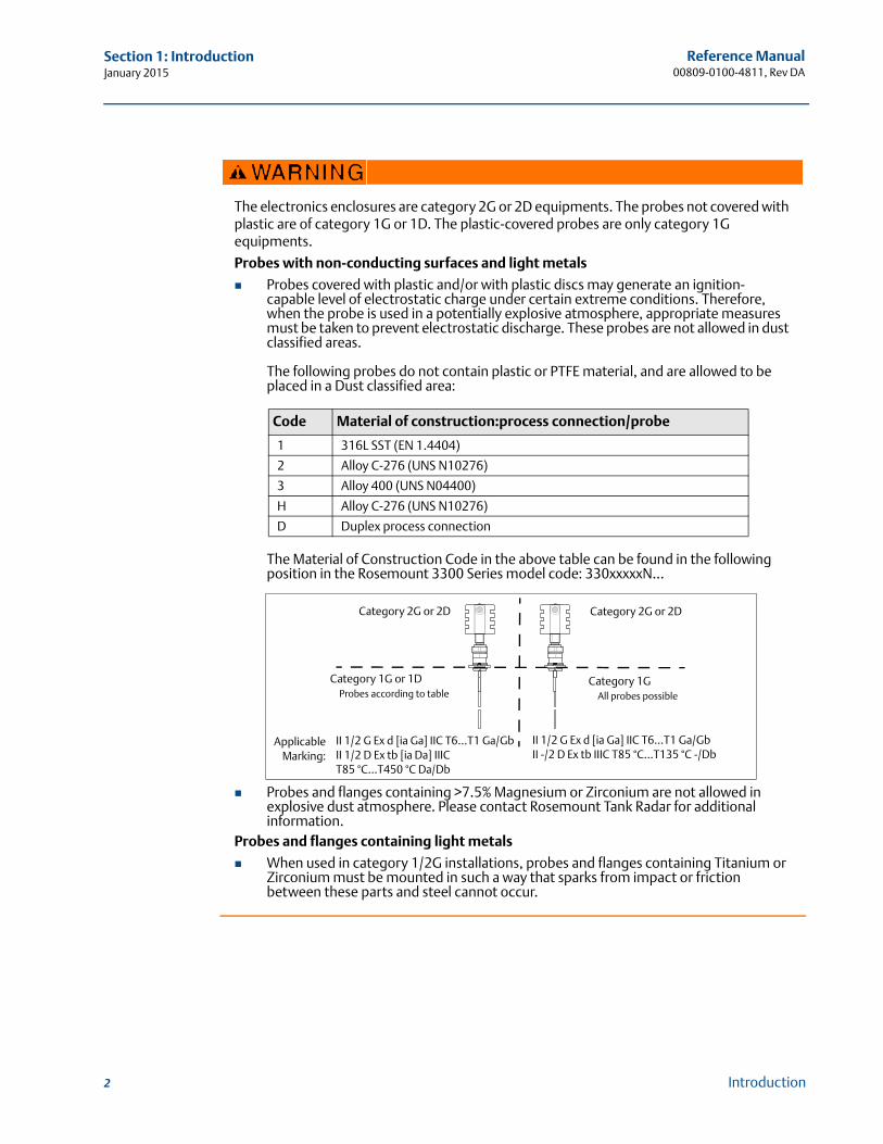
The electronics enclosures are category 2G or 2D equipments. The probes not covered with plastic are of category 1G or 1D. The plastic-covered probes are only category 1G equipments.
Probes with non-conducting surfaces and light metals
Probes covered with plastic and/or with plastic discs may generate an ignition- capable level of electrostatic charge under certain extreme conditions. Therefore, when the probe is used in a potentially explosive atmosphere, appropriate measures must be taken to prevent electrostatic discharge. These probes are not allowed in dust classified areas.
The following probes do not contain plastic or PTFE material, and are allowed to be placed in a Dust classified area:
The Material of Construction Code in the above table can be found in the following position in the Rosemount 3300 Series model code: 330xxxxxN...
Probes and flanges containing >7.5% Magnesium or Zirconium are not allowed in explosive dust atmosphere. Please contact Rosemount Tank Radar for additional information.
Probes and flanges containing light metals
When used in category 1/2G installations, probes and flanges containing Titanium or Zirconium must be mounted in such a way that sparks from impact or friction between these parts and steel cannot occur.
Code Material of construction:process connection/probe
1 316L SST (EN 1.4404)
2 Alloy C-276 (UNS N10276)
3 Alloy 400 (UNS N04400)
H Alloy C-276 (UNS N10276)
D Duplex process connection
Category 2G or 2D Category 2G or 2D
Category 1G or 1DProbes according to table
Category 1GAll probes possible
ApplicableMarking:
II 1/2 G Ex d [ia Ga] IIC T6...T1 Ga/GbII 1/2 D Ex tb [ia Da] IIIC T85 °C...T450 °C Da/Db
II 1/2 G Ex d [ia Ga] IIC T6...T1 Ga/GbII -/2 D Ex tb IIIC T85 °C...T135 °C -/Db

Reference Manual 00809-0100-4811, Rev DA
Section 1: IntroductionJanuary 2015
Any substitution of non-authorized parts or repair, other than exchanging the complete transmitter head or probe assembly, may jeopardize safety and is prohibited.
Unauthorized changes to the product are strictly prohibited as they may unintentionally and unpredictably alter performance and jeopardize safety. Unauthorized changes that interfere with the integrity of the welds or flanges, such as making additional perforations, compromise product integrity and safety. Equipment ratings and certifications are no longer valid on any products that have been damaged or modified without the prior written permission of Emerson Process Management. Any continued use of product that has been damaged or modified without prior written authorization is at the customer's sole risk and expense.
3Introduction
Reference Manual00809-0100-4811, Rev DA
Section 1: IntroductionJanuary 2015
4 Introduction
1.2 Manual overview
This manual provides installation, configuration and maintenance information for the Rosemount 3300 Series Radar Transmitter.
Section 2: Transmitter Overview Theory of operation
Application examples
System architecture
Process and vessel characteristics
Description of the transmitter
Section 3: Installation Mounting considerations
Mechanical installation
Electrical installation
Section 4: Basic Configuration/Start-Up Configuration instructions
Configuration using the HART Communicator
Configuration using the RCT software
Section 5: Operation Display functionality
Error messages
Alarm and write protection
Section 6: Service and Troubleshooting Advanced configuration
Service
Diagnostic messages
Appendix A: Reference Data Specifications
Ordering Information
Appendix B: Product Certifications Examples of labels
EU conformity
European ATEX Directive information
FM approvals
CSA approvals
Approval drawings
Appendix C: Rosemount 3300 Series with HART® to Modbus® Converter Installation, configuration, and troubleshooting of the HART to Modbus Converter
Reference Manual 00809-0100-4811, Rev DA
Section 1: IntroductionJanuary 2015
1.3 Service support
To expedite the return process outside of the United States, contact the nearest Emerson Process Management representative.
Within the United States, call the Emerson Process Management Instrument and Valves Response Center using the 1-800-654-RSMT (7768) toll-free number. This center, available 24 hours a day, will assist you with any needed information or materials.
The center will ask for product model and serial numbers, and will provide a Return Material Authorization (RMA) number. The center will also ask for the process material to which the product was last exposed.
Emerson Process Management Instrument and Valves Response Center representatives will explain the additional information and procedures necessary to return goods exposed to hazardous substances.
1.4 Product recycling/disposal
Recycling of equipment and packaging should be taken into consideration and disposed of in accordance with local and national legislation/regulations.
Individuals who handle products exposed to a hazardous substance can avoid injury if they are informed of and understand the hazard. If the product being returned was exposed to a hazardous substance as defined by Occupational Safety and Health Administration (OSHA), a copy of the required Material Safety Data Sheet (MSDS) for each hazardous substance identified must be included with the returned goods.
5Introduction

6
Reference Manual00809-0100-4811, Rev DA
Section 1: IntroductionJanuary 2015
Introduction
Reference Manual 00809-0100-4811, Rev DA
Section 2: Transmitter OverviewJanuary 2015
Section 2 Transmitter Overview
Theory of operation . . . . . . . . . . . . . . . . . . . . . . . . . . . . . . . . . . . . . . . . . . . . . . . . . . . . . . . . . 7Application examples . . . . . . . . . . . . . . . . . . . . . . . . . . . . . . . . . . . . . . . . . . . . . . . . . . . . . . . . 8System architecture . . . . . . . . . . . . . . . . . . . . . . . . . . . . . . . . . . . . . . . . . . . . . . . . . . . . . . . . . 10Process characteristics . . . . . . . . . . . . . . . . . . . . . . . . . . . . . . . . . . . . . . . . . . . . . . . . . . . . . . . 11Vessel characteristics . . . . . . . . . . . . . . . . . . . . . . . . . . . . . . . . . . . . . . . . . . . . . . . . . . . . . . . . 13Components of the transmitter . . . . . . . . . . . . . . . . . . . . . . . . . . . . . . . . . . . . . . . . . . . . . . . 14Probe selection guide . . . . . . . . . . . . . . . . . . . . . . . . . . . . . . . . . . . . . . . . . . . . . . . . . . . . . . . 15
2.1 Theory of operation
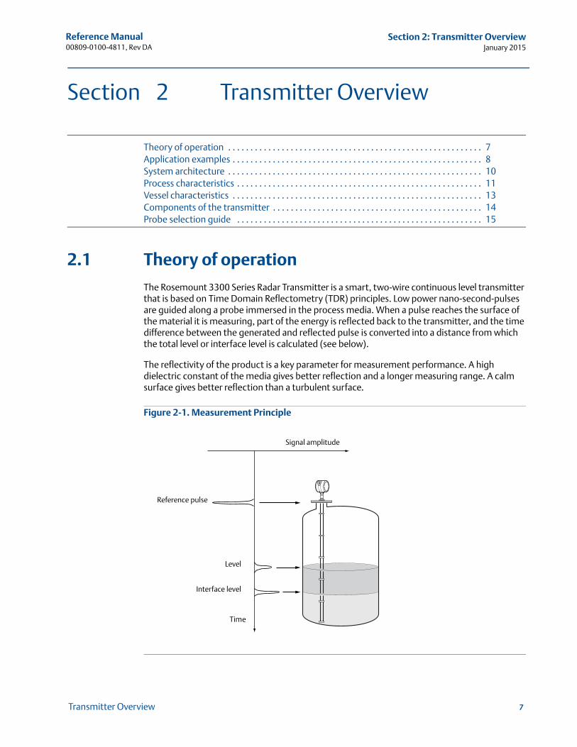
The Rosemount 3300 Series Radar Transmitter is a smart, two-wire continuous level transmitter that is based on Time Domain Reflectometry (TDR) principles. Low power nano-second-pulses are guided along a probe immersed in the process media. When a pulse reaches the surface of the material it is measuring, part of the energy is reflected back to the transmitter, and the time difference between the generated and reflected pulse is converted into a distance from which the total level or interface level is calculated (see below).
The reflectivity of the product is a key parameter for measurement performance. A high dielectric constant of the media gives better reflection and a longer measuring range. A calm surface gives better reflection than a turbulent surface.
Figure 2-1. Measurement Principle
Time
Reference pulse
Level
Interface level
Signal amplitude
7Transmitter Overview
Reference Manual00809-0100-4811, Rev DA
Section 2: Transmitter OverviewJanuary 2015
8 Transmitter Overview
2.2 Application examples
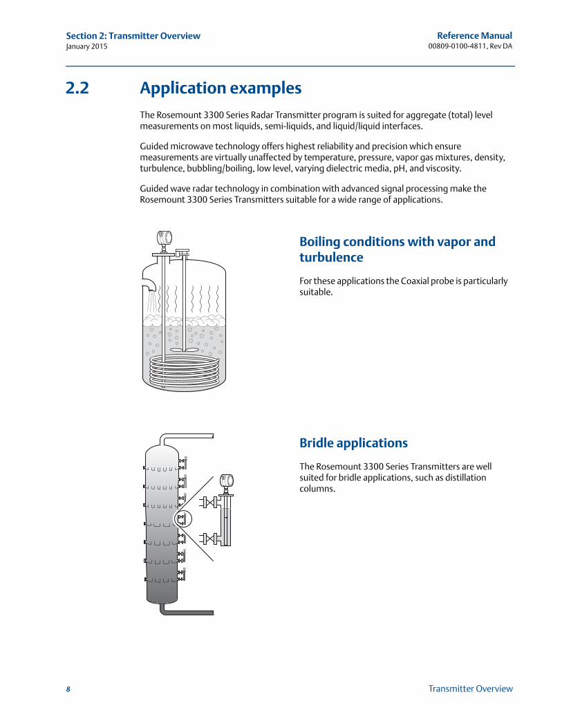
The Rosemount 3300 Series Radar Transmitter program is suited for aggregate (total) level measurements on most liquids, semi-liquids, and liquid/liquid interfaces.
Guided microwave technology offers highest reliability and precision which ensure measurements are virtually unaffected by temperature, pressure, vapor gas mixtures, density, turbulence, bubbling/boiling, low level, varying dielectric media, pH, and viscosity.
Guided wave radar technology in combination with advanced signal processing make the Rosemount 3300 Series Transmitters suitable for a wide range of applications.
Boiling conditions with vapor and turbulence
For these applications the Coaxial probe is particularly suitable.
Bridle applications
The Rosemount 3300 Series Transmitters are well suited for bridle applications, such as distillation columns.
Reference Manual 00809-0100-4811, Rev DA
Section 2: Transmitter OverviewJanuary 2015
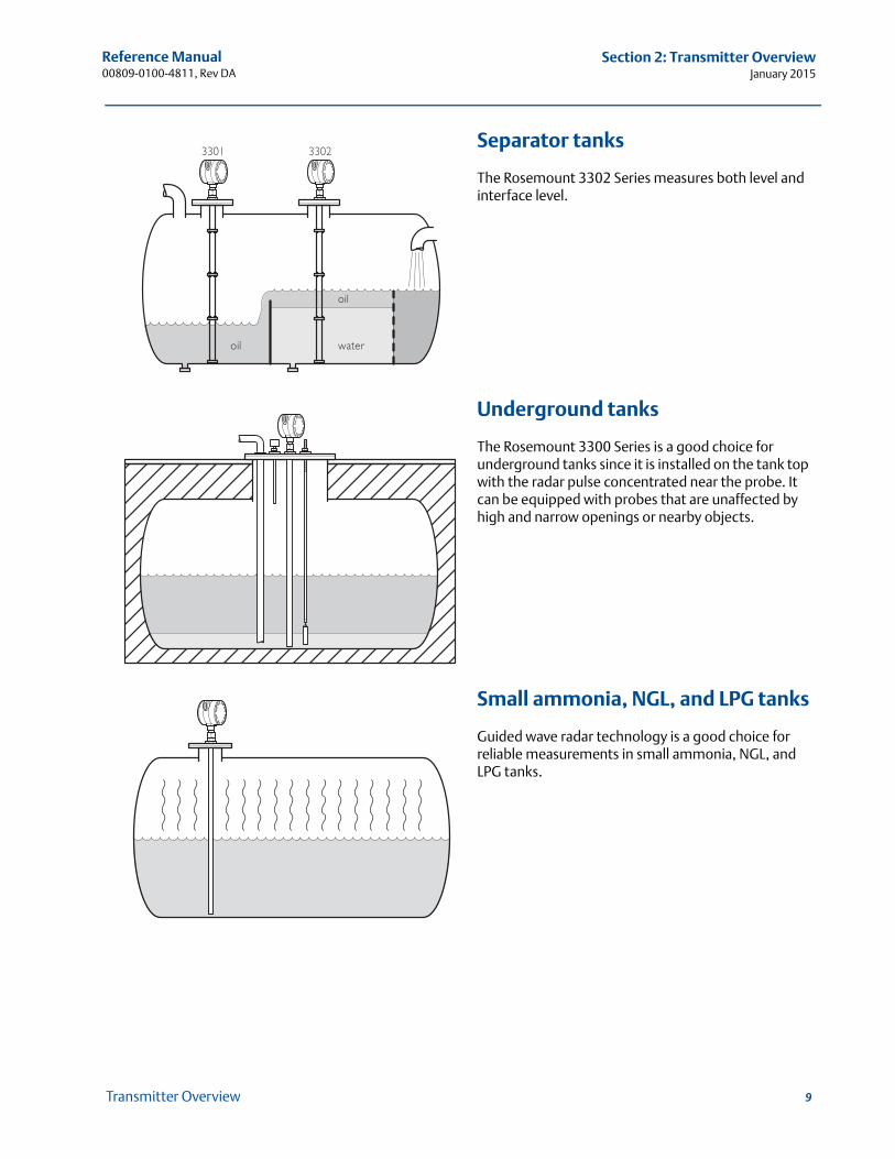
Separator tanks
The Rosemount 3302 Series measures both level and interface level.
Underground tanks
The Rosemount 3300 Series is a good choice for underground tanks since it is installed on the tank top with the radar pulse concentrated near the probe. It can be equipped with probes that are unaffected by high and narrow openings or nearby objects.
Small ammonia, NGL, and LPG tanks
Guided wave radar technology is a good choice for reliable measurements in small ammonia, NGL, and LPG tanks.
9Transmitter Overview
Reference Manual00809-0100-4811, Rev DA
Section 2: Transmitter OverviewJanuary 2015
10 Transmitter Overview
2.3 System architecture
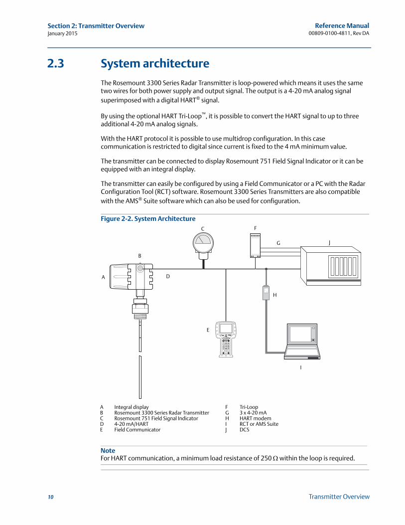
The Rosemount 3300 Series Radar Transmitter is loop-powered which means it uses the same two wires for both power supply and output signal. The output is a 4-20 mA analog signal superimposed with a digital HART® signal.
By using the optional HART Tri-Loop™, it is possible to convert the HART signal to up to three additional 4-20 mA analog signals.
With the HART protocol it is possible to use multidrop configuration. In this case communication is restricted to digital since current is fixed to the 4 mA minimum value.
The transmitter can be connected to display Rosemount 751 Field Signal Indicator or it can be equipped with an integral display.
The transmitter can easily be configured by using a Field Communicator or a PC with the Radar Configuration Tool (RCT) software. Rosemount 3300 Series Transmitters are also compatible with the AMS® Suite software which can also be used for configuration.
Figure 2-2. System Architecture
D
C
E
H
B
J
F
G
I
A
NoteFor HART communication, a minimum load resistance of 250 within the loop is required.
A Integral displayB Rosemount 3300 Series Radar TransmitterC Rosemount 751 Field Signal IndicatorD 4-20 mA/HARTE Field Communicator
F Tri-LoopG 3 x 4-20 mAH HART modemI RCT or AMS SuiteJ DCS
Reference Manual 00809-0100-4811, Rev DA
Section 2: Transmitter OverviewJanuary 2015
2.4 Process characteristics
The Rosemount 3300 Series has high sensitivity due to its advanced signal processing and high signal to noise ratio, which makes it able to handle various disturbances. However, the following circumstances should be considered before mounting the transmitter.
2.4.1 Coating
Coating on the probe should be avoided since the sensitivity of the transmitter may be decreased leading to measurement errors. In viscous or sticky applications, periodic cleaning may be required.
For viscous or sticky applications, it is important to select a suitable probe. For detailed information on the maximum recommended viscosity and coating, see Table A-6 on page 131.
Maximum measurement error due to coating is 1-10% depending on probe type, dielectric constant, coating thickness, and coating height above product surface.
2.4.2 Bridging
Heavy coating that results in product bridging across the two probes for twin lead versions, or between the pipe and the inner rod for coaxial probes, causes erroneous level readings and must be prevented. Single lead probes are preferred in this case. If a twin lead probe is required, regular cleaning may be necessary.
2.4.3 Foam
How well the Rosemount 3300 Series Radar Transmitter measures in foamy applications depends upon the properties of the foam; light and airy or dense and heavy, high or low dielectrics, etc. If the foam is conductive and creamy, the transmitter will probably measure the surface of the foam. If the foam is less conductive, the microwaves will probably penetrate the foam and measure the liquid surface.
2.4.4 Vapor
In some applications, such as ammonia, there is heavy vapor above the product surface that will influence the level measurement. The Rosemount 3300 Series Radar Transmitter can be configured to compensate for the influence of vapor.
2.4.5 Measuring range
The measuring range differs depending on probe type and characteristics of the application. The values given in Table A-4 on page 128 can be used as a guideline for clean liquids.
The maximum measuring range differs depending on application according to:
Disturbing objects close to the probe.
Media with higher dielectric constant (r) give better reflection and allow a longer measuring range.
A calm surface gives better reflection than a turbulent surface. For a turbulent surface, the measuring range might be reduced.
11Transmitter Overview
Reference Manual00809-0100-4811, Rev DA
Section 2: Transmitter OverviewJanuary 2015
12 Transmitter Overview
Surface foam and particles in the tank atmosphere are also circumstances that might affect measuring performance.
Coating/contamination can reduce the measuring range.
Disturbing EMC environment in tank.
2.4.6 Interface
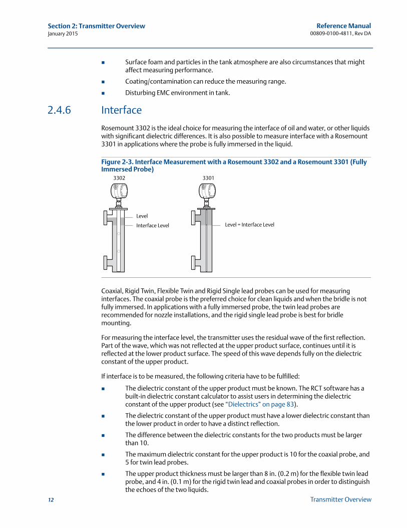
Rosemount 3302 is the ideal choice for measuring the interface of oil and water, or other liquids with significant dielectric differences. It is also possible to measure interface with a Rosemount 3301 in applications where the probe is fully immersed in the liquid.
Figure 2-3. Interface Measurement with a Rosemount 3302 and a Rosemount 3301 (Fully Immersed Probe)
Coaxial, Rigid Twin, Flexible Twin and Rigid Single lead probes can be used for measuring interfaces. The coaxial probe is the preferred choice for clean liquids and when the bridle is not fully immersed. In applications with a fully immersed probe, the twin lead probes are recommended for nozzle installations, and the rigid single lead probe is best for bridle mounting.
For measuring the interface level, the transmitter uses the residual wave of the first reflection. Part of the wave, which was not reflected at the upper product surface, continues until it is reflected at the lower product surface. The speed of this wave depends fully on the dielectric constant of the upper product.
If interface is to be measured, the following criteria have to be fulfilled:
The dielectric constant of the upper product must be known. The RCT software has a built-in dielectric constant calculator to assist users in determining the dielectric constant of the upper product (see “Dielectrics” on page 83).
The dielectric constant of the upper product must have a lower dielectric constant than the lower product in order to have a distinct reflection.
The difference between the dielectric constants for the two products must be larger than 10.
The maximum dielectric constant for the upper product is 10 for the coaxial probe, and 5 for twin lead probes.
The upper product thickness must be larger than 8 in. (0.2 m) for the flexible twin lead probe, and 4 in. (0.1 m) for the rigid twin lead and coaxial probes in order to distinguish the echoes of the two liquids.
Level
3302 3301
Interface Level Level = Interface Level
Reference Manual 00809-0100-4811, Rev DA
Section 2: Transmitter OverviewJanuary 2015
The maximum allowable upper product thickness/measuring range is primarily determined by the dielectric constants of the two liquids.
Target applications include interfaces between oil/oil-like and water/water-like liquids. For such applications, the upper product dielectric constant is low (< 3) and the lower product dielectric constant is high (> 20). The maximum measuring range is only limited by the length of the coaxial and rigid twin lead probes.
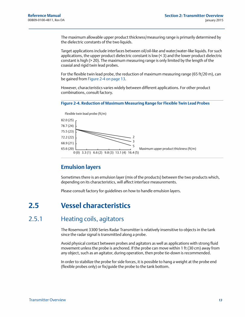
For the flexible twin lead probe, the reduction of maximum measuring range (65 ft/20 m), can be gained from Figure 2-4 on page 13.
However, characteristics varies widely between different applications. For other product combinations, consult factory.
Figure 2-4. Reduction of Maximum Measuring Range for Flexible Twin Lead Probes
Emulsion layers
Sometimes there is an emulsion layer (mix of the products) between the two products which, depending on its characteristics, will affect interface measurements.
Please consult factory for guidelines on how to handle emulsion layers.
2.5 Vessel characteristics
2.5.1 Heating coils, agitators
The Rosemount 3300 Series Radar Transmitter is relatively insensitive to objects in the tank since the radar signal is transmitted along a probe.
Avoid physical contact between probes and agitators as well as applications with strong fluid movement unless the probe is anchored. If the probe can move within 1 ft (30 cm) away from any object, such as an agitator, during operation, then probe tie-down is recommended.
In order to stabilize the probe for side forces, it is possible to hang a weight at the probe end (flexible probes only) or fix/guide the probe to the tank bottom.
Flexible twin lead probe (ft/m)
Maximum upper product thickness (ft/m)
32
5
82.0 (25)
78.7 (24)
75.5 (23)
72.2 (22)
68.9 (21)
65.6 (20)0 (0) 3.3 (1) 6.6 (2) 9.8 (3) 13.1 (4) 16.4 (5)
13Transmitter Overview
Reference Manual00809-0100-4811, Rev DA
Section 2: Transmitter OverviewJanuary 2015
14 Transmitter Overview
2.5.2 Tank shape
The guided wave radar transmitter is insensitive to the tank shape. Since the radar signal travels along a probe, the shape of the tank bottom has virtually no effect on the measurement performance. The transmitter handles flat or dish-bottom tanks equally well.
2.6 Components of the transmitter
The Rosemount 3300 Series Radar Transmitter has an aluminum transmitter housing which contains advanced electronics for signal processing.
The radar electronics produces an electromagnetic pulse which is guided by the probe.
There are different probe types available for various applications: Rigid Twin Lead, Flexible Twin Lead, Rigid Single Lead, Segmented Rigid Single Lead, Flexible Single Lead, and Coaxial.
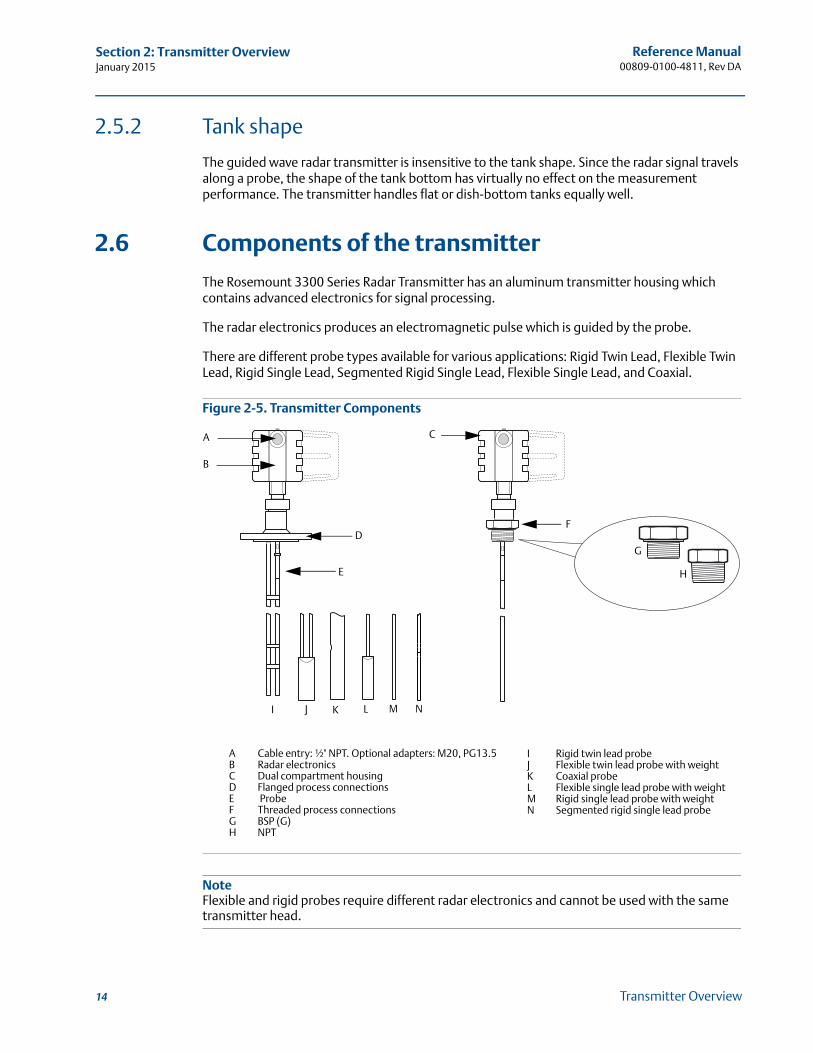
Figure 2-5. Transmitter Components
NoteFlexible and rigid probes require different radar electronics and cannot be used with the same transmitter head.
B
E
CA
FD
G
H
A Cable entry: ½" NPT. Optional adapters: M20, PG13.5B Radar electronicsC Dual compartment housingD Flanged process connectionsE ProbeF Threaded process connectionsG BSP (G)H NPT
I Rigid twin lead probeJ Flexible twin lead probe with weightK Coaxial probeL Flexible single lead probe with weightM Rigid single lead probe with weightN Segmented rigid single lead probe
I J K L M N
Reference Manual 00809-0100-4811, Rev DA
Section 2: Transmitter OverviewJanuary 2015
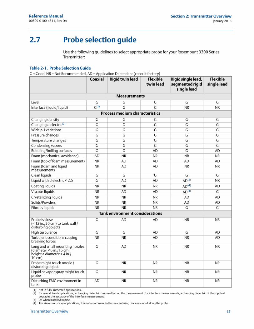
2.7 Probe selection guide
Use the following guidelines to select appropriate probe for your Rosemount 3300 Series Transmitter:
Table 2-1. Probe Selection Guide G = Good, NR = Not Recommended, AD = Application Dependent (consult factory)
Coaxial Rigid twin lead Flexible twin lead
Rigid single lead, segmented rigid
single lead
Flexible single lead
Measurements
Level G G G G GInterface (liquid/liquid) G(1)
(1) Not in fully immersed applications.
G G NR NR
Process medium characteristics
Changing density G G G G GChanging dielectric(2)
(2) For overall level applications, a changing dielectric has no effect on the measurement. For interface measurements, a changing dielectric of the top fluid degrades the accuracy of the interface measurement.
G G G G GWide pH variations G G G G GPressure changes G G G G GTemperature changes G G G G GCondensing vapors G G G G GBubbling/boiling surfaces G G AD G ADFoam (mechanical avoidance) AD NR NR NR NRFoam (top of foam measurement) NR AD AD AD ADFoam (foam and liquid measurement)
NR AD AD NR NR
Clean liquids G G G G GLiquid with dielectric < 2.5 G AD AD AD(3)
(3) OK when installed in pipe.
NR
Coating liquids NR NR NR AD(4) AD
Viscous liquids NR AD AD AD(4)
(4) For viscous or sticky applications, it is not recommended to use centering discs mounted along the probe.
G
Crystallizing liquids NR NR NR AD ADSolids/Powders NR NR NR AD ADFibrous liquids NR NR NR G G
Tank environment considerations
Probe is close (< 12 in./30 cm) to tank wall / disturbing objects
G AD AD NR NR
High turbulence G G AD G ADTurbulent conditions causing breaking forces
NR NR AD NR AD
Long and small mounting nozzles(diameter < 6 in./15 cm,height > diameter + 4 in./10 cm)
G AD NR NR NR
Probe might touch nozzle / disturbing object
G NR NR NR NR
Liquid or vapor spray might touch probe
G NR NR NR NR
Disturbing EMC environment in tank
AD NR NR NR NR
15Transmitter Overview
Reference Manual00809-0100-4811, Rev DA
Section 2: Transmitter OverviewJanuary 2015
16 Transmitter Overview
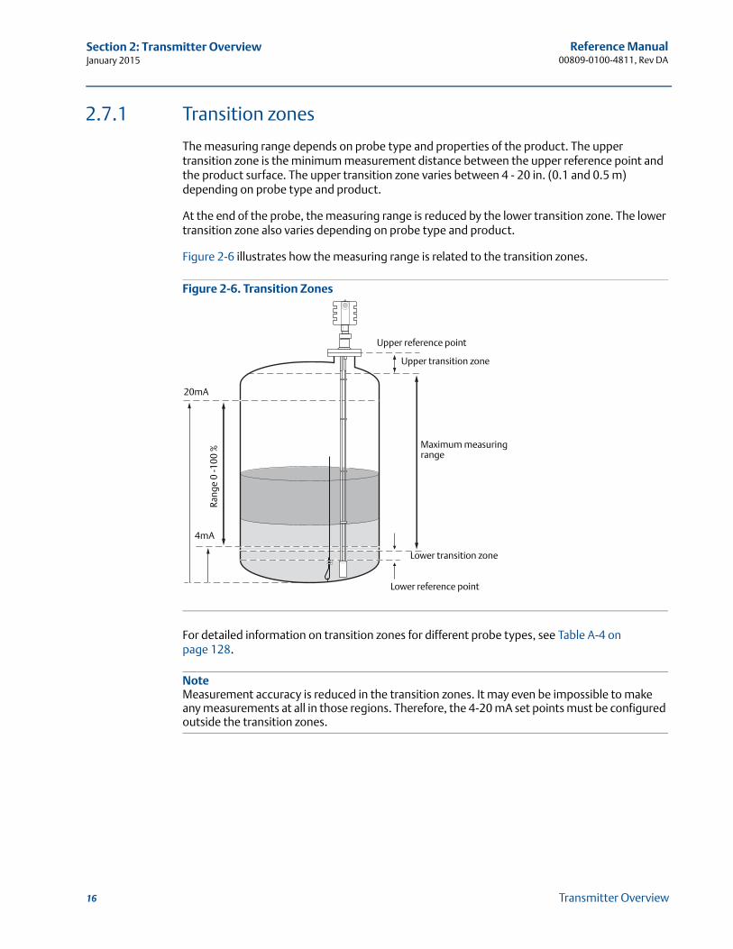
2.7.1 Transition zones
The measuring range depends on probe type and properties of the product. The upper transition zone is the minimum measurement distance between the upper reference point and the product surface. The upper transition zone varies between 4 - 20 in. (0.1 and 0.5 m) depending on probe type and product.
At the end of the probe, the measuring range is reduced by the lower transition zone. The lower transition zone also varies depending on probe type and product.
Figure 2-6 illustrates how the measuring range is related to the transition zones.
Figure 2-6. Transition Zones
For detailed information on transition zones for different probe types, see Table A-4 on page 128.
NoteMeasurement accuracy is reduced in the transition zones. It may even be impossible to make any measurements at all in those regions. Therefore, the 4-20 mA set points must be configured outside the transition zones.
4mA
20mA
Upper transition zone
Lower transition zone
Rang
e 0
-100
%
Maximum measuring range
Upper reference point
Lower reference point

Reference Manual 00809-0100-4811, Rev DA
Section 3: InstallationJanuary 2015
Section 3 Installation
Safety messages . . . . . . . . . . . . . . . . . . . . . . . . . . . . . . . . . . . . . . . . . . . . . . . . . . . . . . . . . . . . 17Installation procedure . . . . . . . . . . . . . . . . . . . . . . . . . . . . . . . . . . . . . . . . . . . . . . . . . . . . . . . 19Before you install . . . . . . . . . . . . . . . . . . . . . . . . . . . . . . . . . . . . . . . . . . . . . . . . . . . . . . . . . . . . 20Mounting considerations . . . . . . . . . . . . . . . . . . . . . . . . . . . . . . . . . . . . . . . . . . . . . . . . . . . . 22Mechanical installation . . . . . . . . . . . . . . . . . . . . . . . . . . . . . . . . . . . . . . . . . . . . . . . . . . . . . . 29Electrical installation . . . . . . . . . . . . . . . . . . . . . . . . . . . . . . . . . . . . . . . . . . . . . . . . . . . . . . . . 52Optional devices . . . . . . . . . . . . . . . . . . . . . . . . . . . . . . . . . . . . . . . . . . . . . . . . . . . . . . . . . . . . 58
3.1 Safety messages
Procedures and instructions in this section may require special precautions to ensure the safety of the personnel performing the operations. Information that raises potential safety issues is
indicated by a warning symbol ( ). Please refer to the following safety messages before performing an operation preceded by this symbol.
Explosions could result in death or serious injury.
Verify that the operating environment of the transmitter is consistent with the appropriate hazardous locations certifications.
Before connecting a HART®-based communicator in an explosive atmosphere, make sure the instruments in the loop are installed in accordance with intrinsically safe or non-incendive field wiring practices.
In an Explosion-proof/flameproof installation, do not remove the transmitter cover when power is applied to the unit.
Eliminate the risk of ESD discharge prior to dismounting the transmitter head. Probes may generate an ignition- capable level of electrostatic charge under extreme
conditions. During any type of installation or maintenance in a potentially explosive atmosphere, the responsible person should make sure that any ESD risks are eliminated before attempting to separate the probe from the transmitter head.
17Installation

Reference Manual00809-0100-4811, Rev DA
Section 3: InstallationJanuary 2015
Failure to follow safe installation and servicing guidelines could result in death or serious injury.
Make sure only qualified personnel perform the installation. Use the equipment only as specified in this manual. Failure to do so may impair the
protection provided by the equipment. Do not perform any service other than those contained in this manual unless you are
qualified.Process leaks could result in death or serious injury.
Make sure that the transmitter is handled carefully. If the Process Seal is damaged, gas might escape from the tank when the transmitter head is removed from the probe.
High voltage that may be present on leads could cause electrical shock.
Avoid contact with leads and terminals. Make sure the main power to the Rosemount 3300 Series Transmitter is off and the
lines to any other external power source are disconnected or not powered while wiring the gauge.
Probes covered with plastic and/or with plastic discs may generate an ignition-capable level of electrostatic charge under certain extreme conditions. Therefore, when the probe is used in a potentially explosive atmosphere, appropriate measures must be taken to prevent electrostatic discharge.
18 Installation
Reference Manual 00809-0100-4811, Rev DA
Section 3: InstallationJanuary 2015
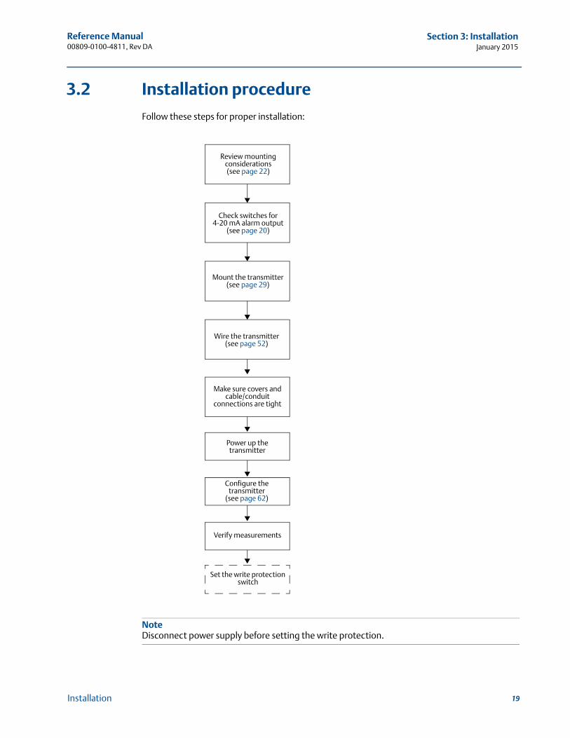
3.2 Installation procedure
Follow these steps for proper installation:
NoteDisconnect power supply before setting the write protection.
Review mounting considerations(see page 22)
Check switches for 4-20 mA alarm output
(see page 20)
Mount the transmitter(see page 29)
Wire the transmitter(see page 52)
Make sure covers and cable/conduit
connections are tight
Power up the transmitter
Configure the transmitter
(see page 62)
Verify measurements
Set the write protection switch
19Installation
Reference Manual00809-0100-4811, Rev DA
Section 3: InstallationJanuary 2015
3.3 Before you install
3.3.1 Alarm and write protection switches
Electronic boards are electrostatically sensitive. Failure to observe proper handling precautions for static-sensitive components can result in damage to the electronic components. Do not remove the electronic boards from the Rosemount 3300 Series Radar Transmitter.
NoteTo ensure long life for your radar transmitter, and to comply with hazardous location installation requirements, tighten covers on both sides of the electronics housing.
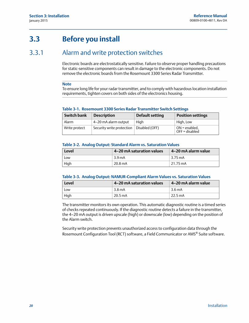
Table 3-1. Rosemount 3300 Series Radar Transmitter Switch Settings
Table 3-2. Analog Output: Standard Alarm vs. Saturation Values
Table 3-3. Analog Output: NAMUR-Compliant Alarm Values vs. Saturation Values
The transmitter monitors its own operation. This automatic diagnostic routine is a timed series of checks repeated continuously. If the diagnostic routine detects a failure in the transmitter, the 4–20 mA output is driven upscale (high) or downscale (low) depending on the position of the Alarm switch.
Security write protection prevents unauthorized access to configuration data through the Rosemount Configuration Tool (RCT) software, a Field Communicator or AMS® Suite software.
Switch bank Description Default setting Position settings
Alarm 4–20 mA alarm output High High, Low
Write protect Security write protection Disabled (OFF) ON = enabled, OFF = disabled
Level 4–20 mA saturation values 4–20 mA alarm value
Low 3.9 mA 3.75 mA
High 20.8 mA 21.75 mA
Level 4–20 mA saturation values 4–20 mA alarm value
Low 3.8 mA 3.6 mA
High 20.5 mA 22.5 mA
20 Installation
Reference Manual 00809-0100-4811, Rev DA
Section 3: InstallationJanuary 2015
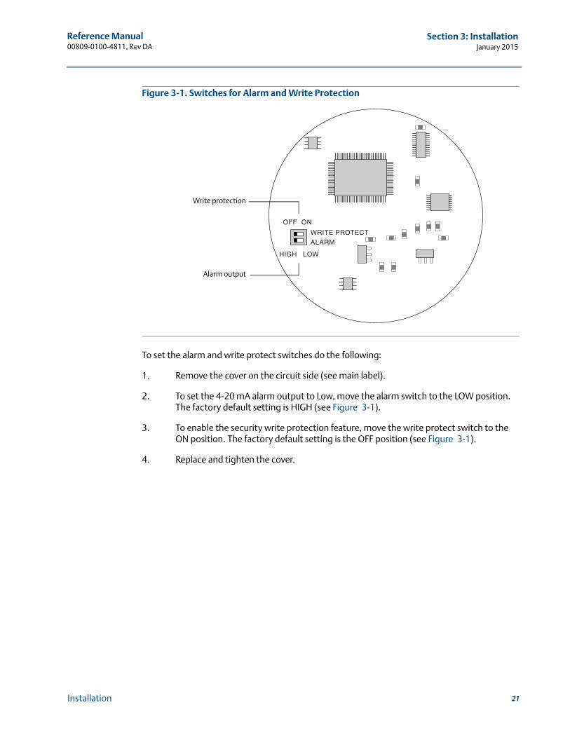
Figure 3-1. Switches for Alarm and Write Protection
To set the alarm and write protect switches do the following:
1. Remove the cover on the circuit side (see main label).
2. To set the 4-20 mA alarm output to Low, move the alarm switch to the LOW position. The factory default setting is HIGH (see Figure 3-1).
3. To enable the security write protection feature, move the write protect switch to the ON position. The factory default setting is the OFF position (see Figure 3-1).
4. Replace and tighten the cover.
Alarm output
Write protection
21Installation

Reference Manual00809-0100-4811, Rev DA
Section 3: InstallationJanuary 2015
3.4 Mounting considerations
Before installing the Rosemount 3300 Series Radar Transmitter, consider specific mounting requirements, vessel characteristics, and process characteristics.
3.4.1 Process connection
The Rosemount 3300 Series has a threaded connection for easy mounting on the tank roof. It can also be mounted on a nozzle by using different flanges.
Threaded connection
Figure 3-2. Mounting on Tank Roof Using Threaded Connection
Mounting on tank roof.
Mounting in threaded pipe.
22 Installation
Reference Manual 00809-0100-4811, Rev DA
Section 3: InstallationJanuary 2015
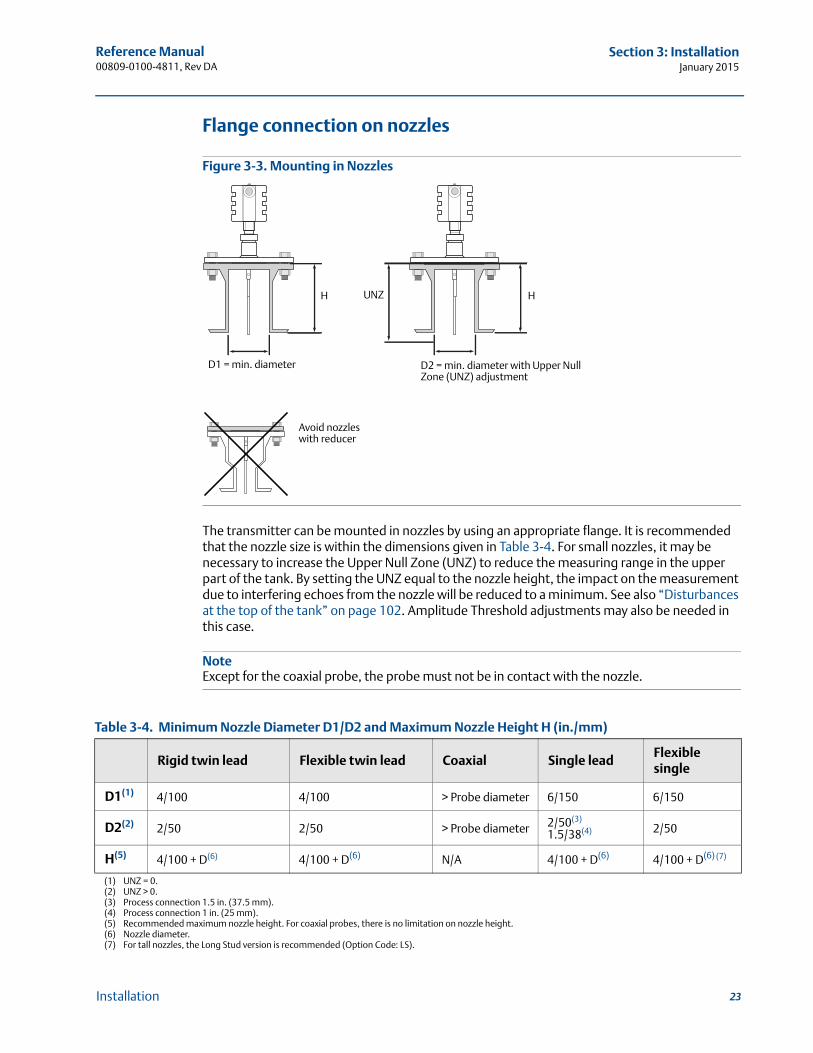
Flange connection on nozzles
Figure 3-3. Mounting in Nozzles
The transmitter can be mounted in nozzles by using an appropriate flange. It is recommended that the nozzle size is within the dimensions given in Table 3-4. For small nozzles, it may be necessary to increase the Upper Null Zone (UNZ) to reduce the measuring range in the upper part of the tank. By setting the UNZ equal to the nozzle height, the impact on the measurement due to interfering echoes from the nozzle will be reduced to a minimum. See also “Disturbances at the top of the tank” on page 102. Amplitude Threshold adjustments may also be needed in this case.
NoteExcept for the coaxial probe, the probe must not be in contact with the nozzle.
Table 3-4. Minimum Nozzle Diameter D1/D2 and Maximum Nozzle Height H (in./mm)
Rigid twin lead Flexible twin lead Coaxial Single leadFlexible single
D1(1)
(1) UNZ = 0.
4/100 4/100 > Probe diameter 6/150 6/150
D2(2)
(2) UNZ > 0.
2/50 2/50 > Probe diameter 2/50(3)
1.5/38(4)
(3) Process connection 1.5 in. (37.5 mm).(4) Process connection 1 in. (25 mm).
2/50
H(5)
(5) Recommended maximum nozzle height. For coaxial probes, there is no limitation on nozzle height.
4/100 + D(6)
(6) Nozzle diameter.
4/100 + D(6) N/A 4/100 + D(6) 4/100 + D(6) (7)
(7) For tall nozzles, the Long Stud version is recommended (Option Code: LS).
H
D2 = min. diameter with Upper Null Zone (UNZ) adjustment
HUNZ
Avoid nozzles with reducer
D1 = min. diameter
23Installation

Reference Manual00809-0100-4811, Rev DA
Section 3: InstallationJanuary 2015
3.4.2 Installation of single lead probes in non-metallic tanks
For optimal single lead probe performance in non-metallic tanks, the probe must be mounted with a metal flange, or screwed in to a metal sheet (d > 14 in./350 mm) if the threaded version is used.
Figure 3-4. Mounting in Non-Metallic Tanks
Avoid disturbing Electro Magnetic Compatibility (EMC) environment near the tank. Installation in metallic tank is recommended.
3.4.3 Mounting in still pipes/bypass pipes
In order to prevent the probe from contacting the bridle wall when replacing displacers or installing in pipes, centering discs are available for the Rigid Single, Segmented Rigid Single, Flexible Single, and Flexible Twin Lead probes. The disc is attached to the end of the probe and thus keeps the probe centered in the bridle. The discs are available in stainless steel, Alloy C-276, Alloy 400, and PTFE. See also “Mounting a centering disc for pipe installations” on page 49.
NoteIt is not recommended that flexible probes are installed in bypass pipes.
Rigid single lead, segmented rigid single lead Pipe diameter Ø2 in. (50 mm)
Inlet pipe diameter N < Ø
L 12 in. (300 mm)
Metal flange d > 2 in. /DN50
Metal sheet d > 14 in. /350 mm
24 Installation
Reference Manual 00809-0100-4811, Rev DA
Section 3: InstallationJanuary 2015
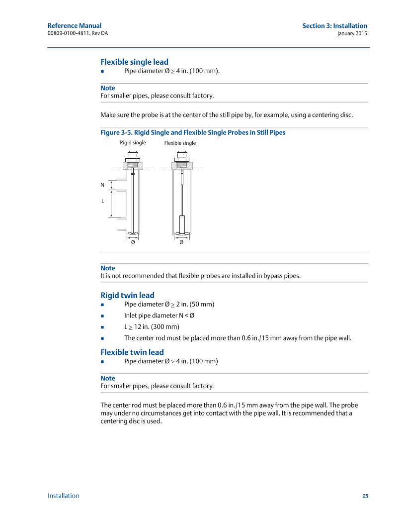
Flexible single lead Pipe diameter Ø 4 in. (100 mm).
NoteFor smaller pipes, please consult factory.
Make sure the probe is at the center of the still pipe by, for example, using a centering disc.
Figure 3-5. Rigid Single and Flexible Single Probes in Still Pipes
NoteIt is not recommended that flexible probes are installed in bypass pipes.
Rigid twin lead Pipe diameter Ø 2 in. (50 mm)
Inlet pipe diameter N < Ø
L 12 in. (300 mm)
The center rod must be placed more than 0.6 in./15 mm away from the pipe wall.
Flexible twin lead Pipe diameter Ø 4 in. (100 mm)
NoteFor smaller pipes, please consult factory.
The center rod must be placed more than 0.6 in./15 mm away from the pipe wall. The probe may under no circumstances get into contact with the pipe wall. It is recommended that a centering disc is used.
Ø
L
N
Rigid single
Ø
Flexible single
25Installation
Reference Manual00809-0100-4811, Rev DA
Section 3: InstallationJanuary 2015
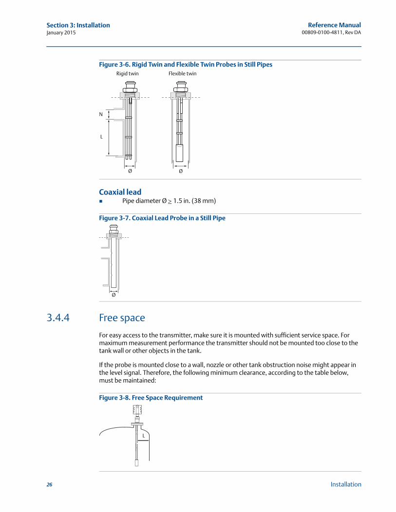
Figure 3-6. Rigid Twin and Flexible Twin Probes in Still Pipes
Coaxial lead Pipe diameter Ø 1.5 in. (38 mm)
Figure 3-7. Coaxial Lead Probe in a Still Pipe
3.4.4 Free space
For easy access to the transmitter, make sure it is mounted with sufficient service space. For maximum measurement performance the transmitter should not be mounted too close to the tank wall or other objects in the tank.
If the probe is mounted close to a wall, nozzle or other tank obstruction noise might appear in the level signal. Therefore, the following minimum clearance, according to the table below, must be maintained:
Figure 3-8. Free Space Requirement
Ø
Flexible twin
Ø
Rigid twin
N
L
Ø
L
26 Installation
Reference Manual 00809-0100-4811, Rev DA
Section 3: InstallationJanuary 2015
For information on the recommended minimum free space (L) to tank wall or other objects in the tank, see Table 3-5.
Table 3-5. Recommended Minimum Free Space (L)
For information on the recommended minimum free space (L) to tank wall or other objects in the tank in the case of rigid single, segmented rigid single and flexible single lead probes, see Table 3-6.
Table 3-6. Free Space (L) Requirements - Single Lead Probes
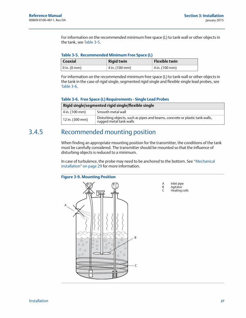
3.4.5 Recommended mounting position
When finding an appropriate mounting position for the transmitter, the conditions of the tank must be carefully considered. The transmitter should be mounted so that the influence of disturbing objects is reduced to a minimum.
In case of turbulence, the probe may need to be anchored to the bottom. See “Mechanical installation” on page 29 for more information.
Figure 3-9. Mounting Position
Coaxial Rigid twin Flexible twin
0 in. (0 mm) 4 in. (100 mm) 4 in. (100 mm)
Rigid single/segmented rigid single/flexible single
4 in. (100 mm) Smooth metal wall
12 in. (300 mm) Disturbing objects, such as pipes and beams, concrete or plastic tank walls, rugged metal tank walls
A
C
B
A Inlet pipeB AgitatorC Heating coils
27Installation
Reference Manual00809-0100-4811, Rev DA
Section 3: InstallationJanuary 2015
The following guidelines should be considered when mounting the transmitter:
Do not mount close to inlet pipes.
Do not mount close to agitators. If the probe can move to within 11.8 in. (30 cm) away from an agitator, a probe tie-down is recommended.
If the probe tends to sway due to turbulent conditions in the tank, the probe should be anchored to the tank bottom.
Avoid mounting close to heating coils.
Make sure the nozzle does not extend into the tank.
Make sure the probe does not come into contact with the nozzle or other objects in the tank.
Position the probe such that it is subject to a minimum of lateral force.
NoteViolent fluid movements causing high sideway forces may break rigid probes.
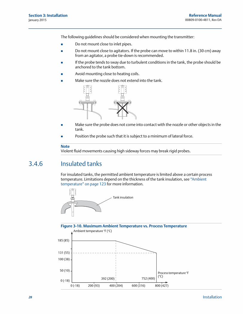
3.4.6 Insulated tanks
For insulated tanks, the permitted ambient temperature is limited above a certain process temperature. Limitations depend on the thickness of the tank insulation, see “Ambient temperature” on page 123 for more information.
Figure 3-10. Maximum Ambient Temperature vs. Process Temperature
Tank insulation
Process temperature °F (°C)
Ambient temperature °F (°C)
185 (85)
131 (55)
100 (38)
50 (10)
0 (-18)
0 (-18) 200 (93) 400 (204)
392 (200)
600 (316)
752 (400)
800 (427)
28 Installation

Reference Manual 00809-0100-4811, Rev DA
Section 3: InstallationJanuary 2015
3.5 Mechanical installationMount the transmitter with flange on a nozzle on top of the tank. The transmitter can also be mounted on a threaded connection. Make sure only qualified personnel perform the installation.
NoteIf you need to remove the transmitter head from the probe, make sure the process seal is carefully protected from dust and water. See “Removing the transmitter head” on page 110 for further information.
For safety information, see Warnings on page 17.
3.5.1 Tank connection with flange
Figure 3-11. Tank Connection with Flange
1. Place a gasket on top of the tank flange.
2. Lower the transmitter and probe with flange into the tank.
3. Tighten the bolts.
4. Loosen the nut that connects the transmitter housing to the probe slightly.
5. Rotate the transmitter housing so that the cable entries/display face the desired direction.
6. Tighten the nut.
NotePTFE covered probes must be handled carefully to prevent damage to the coating.
C
F
D
G
A
E
B
A NutB BoltsC Transmitter headD FlangeE ProbeF GasketG Tank flange
29Installation
Reference Manual00809-0100-4811, Rev DA
Section 3: InstallationJanuary 2015
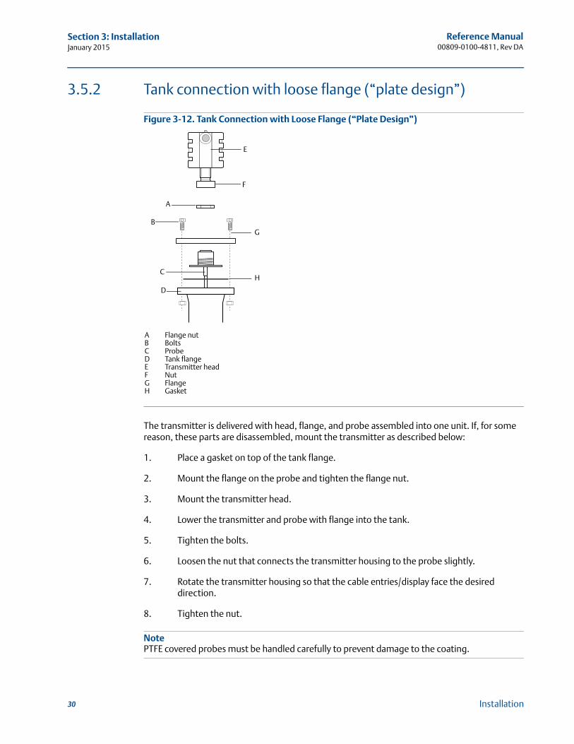
3.5.2 Tank connection with loose flange (“plate design”)
Figure 3-12. Tank Connection with Loose Flange (“Plate Design”)
The transmitter is delivered with head, flange, and probe assembled into one unit. If, for some reason, these parts are disassembled, mount the transmitter as described below:
1. Place a gasket on top of the tank flange.
2. Mount the flange on the probe and tighten the flange nut.
3. Mount the transmitter head.
4. Lower the transmitter and probe with flange into the tank.
5. Tighten the bolts.
6. Loosen the nut that connects the transmitter housing to the probe slightly.
7. Rotate the transmitter housing so that the cable entries/display face the desired direction.
8. Tighten the nut.
NotePTFE covered probes must be handled carefully to prevent damage to the coating.
E
H
G
D
C
A
B
F
A Flange nutB BoltsC ProbeD Tank flangeE Transmitter headF NutG FlangeH Gasket
30 Installation
Reference Manual 00809-0100-4811, Rev DA
Section 3: InstallationJanuary 2015
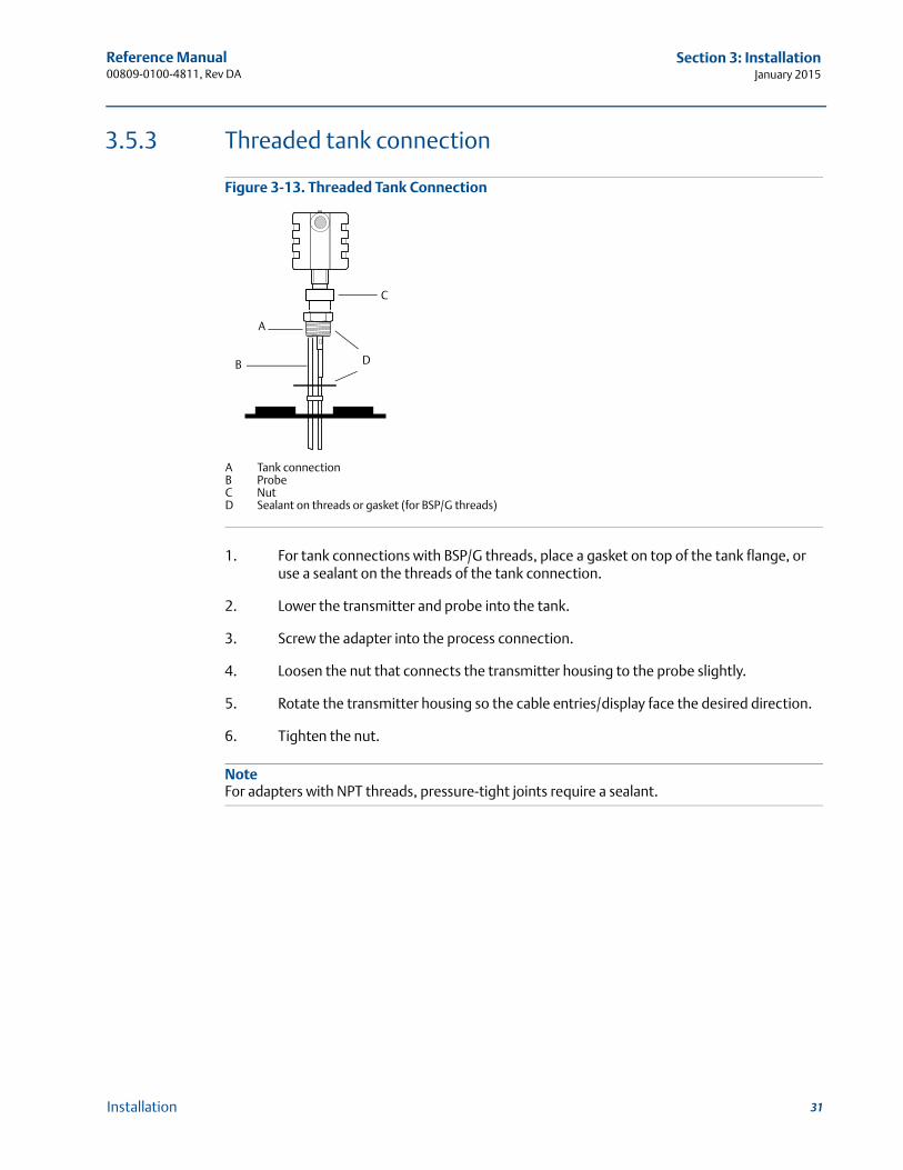
3.5.3 Threaded tank connection
Figure 3-13. Threaded Tank Connection
1. For tank connections with BSP/G threads, place a gasket on top of the tank flange, or use a sealant on the threads of the tank connection.
2. Lower the transmitter and probe into the tank.
3. Screw the adapter into the process connection.
4. Loosen the nut that connects the transmitter housing to the probe slightly.
5. Rotate the transmitter housing so the cable entries/display face the desired direction.
6. Tighten the nut.
NoteFor adapters with NPT threads, pressure-tight joints require a sealant.
D
C
A
B
A Tank connectionB ProbeC NutD Sealant on threads or gasket (for BSP/G threads)
31Installation
Reference Manual00809-0100-4811, Rev DA
Section 3: InstallationJanuary 2015
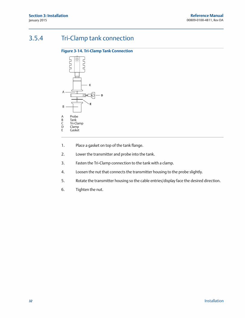
3.5.4 Tri-Clamp tank connection
Figure 3-14. Tri-Clamp Tank Connection
1. Place a gasket on top of the tank flange.
2. Lower the transmitter and probe into the tank.
3. Fasten the Tri-Clamp connection to the tank with a clamp.
4. Loosen the nut that connects the transmitter housing to the probe slightly.
5. Rotate the transmitter housing so the cable entries/display face the desired direction.
6. Tighten the nut.
A
B
C
D
E
A ProbeB TankC Tri-ClampD ClampE Gasket
32 Installation
Reference Manual 00809-0100-4811, Rev DA
Section 3: InstallationJanuary 2015
3.5.5 Shortening the probe
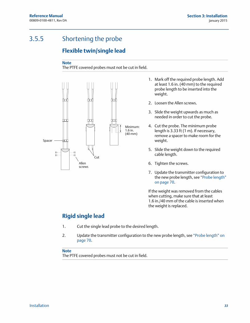
Flexible twin/single lead
NoteThe PTFE covered probes must not be cut in field.
Rigid single lead
1. Cut the single lead probe to the desired length.
2. Update the transmitter configuration to the new probe length, see “Probe length” on page 70.
NoteThe PTFE covered probes must not be cut in field.
1. Mark off the required probe length. Add at least 1.6 in. (40 mm) to the required probe length to be inserted into the weight.
2. Loosen the Allen screws.
3. Slide the weight upwards as much as needed in order to cut the probe.
4. Cut the probe. The minimum probe length is 3.33 ft (1 m). If necessary, remove a spacer to make room for the weight.
5. Slide the weight down to the required cable length.
6. Tighten the screws.
7. Update the transmitter configuration to the new probe length, see “Probe length” on page 70.
If the weight was removed from the cables when cutting, make sure that at least 1.6 in./40 mm of the cable is inserted when the weight is replaced.
Allen screws
Minimum:1.6 in. (40 mm)
Spacer
Cut
33Installation
Reference Manual00809-0100-4811, Rev DA
Section 3: InstallationJanuary 2015
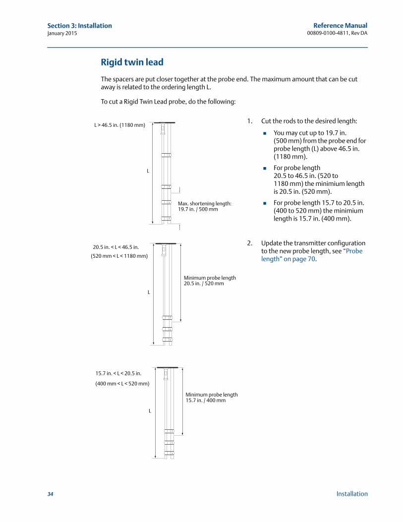
Rigid twin lead
The spacers are put closer together at the probe end. The maximum amount that can be cut away is related to the ordering length L.
To cut a Rigid Twin Lead probe, do the following:
1. Cut the rods to the desired length:
You may cut up to 19.7 in.(500 mm) from the probe end for probe length (L) above 46.5 in. (1180 mm).
For probe length 20.5 to 46.5 in. (520 to 1180 mm) the minimium length is 20.5 in. (520 mm).
For probe length 15.7 to 20.5 in. (400 to 520 mm) the minimium length is 15.7 in. (400 mm).
2. Update the transmitter configuration to the new probe length, see “Probe length” on page 70.
Max. shortening length: 19.7 in. / 500 mm
L > 46.5 in. (1180 mm)
L
20.5 in. < L < 46.5 in.
Minimum probe length20.5 in. / 520 mm
L
(520 mm < L < 1180 mm)
Minimum probe length15.7 in. / 400 mm
L
15.7 in. < L < 20.5 in.
(400 mm < L < 520 mm)
34 Installation
Reference Manual 00809-0100-4811, Rev DA
Section 3: InstallationJanuary 2015
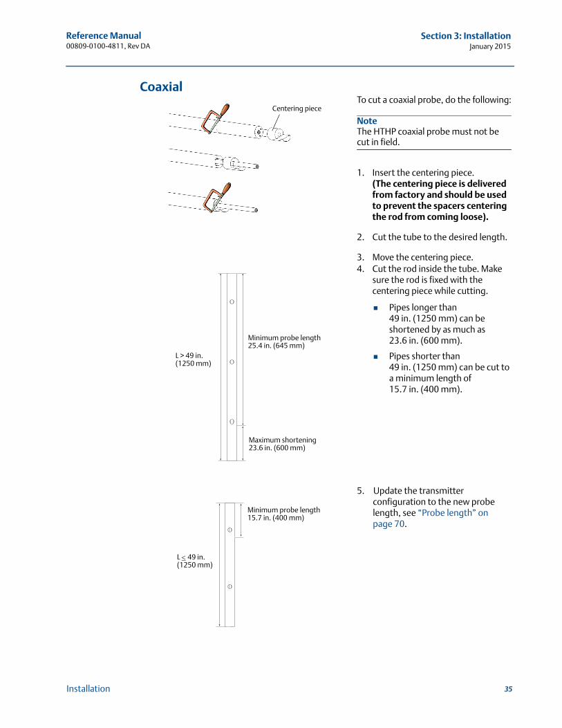
CoaxialTo cut a coaxial probe, do the following:
NoteThe HTHP coaxial probe must not be cut in field.
1. Insert the centering piece.(The centering piece is delivered from factory and should be used to prevent the spacers centering the rod from coming loose).
2. Cut the tube to the desired length.
3. Move the centering piece.4. Cut the rod inside the tube. Make
sure the rod is fixed with the centering piece while cutting.
Pipes longer than 49 in. (1250 mm) can be shortened by as much as 23.6 in. (600 mm).
Pipes shorter than 49 in. (1250 mm) can be cut to a minimum length of 15.7 in. (400 mm).
5. Update the transmitter configuration to the new probe length, see “Probe length” on page 70.
Centering piece
Maximum shortening 23.6 in. (600 mm)
L > 49 in. (1250 mm)
Minimum probe length25.4 in. (645 mm)
Minimum probe length15.7 in. (400 mm)
L 49 in.(1250 mm)
35Installation
Reference Manual00809-0100-4811, Rev DA
Section 3: InstallationJanuary 2015
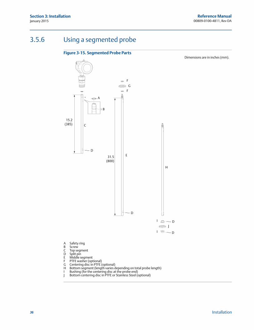
3.5.6 Using a segmented probe
Figure 3-15. Segmented Probe Parts
A
B
DE
F
C
I
J
D
F
G
H
I
D
D
A Safety ringB ScrewC Top segmentD Split pinE Middle segmentF PTFE washer (optional)G Centering disc in PTFE (optional)H Bottom segment (length varies depending on total probe length)I Bushing (for the centering disc at the probe end)J Bottom centering disc in PTFE or Stainless Steel (optional)
15.2(385)
31.5(800)
Dimensions are in inches (mm).
36 Installation
Reference Manual 00809-0100-4811, Rev DA
Section 3: InstallationJanuary 2015
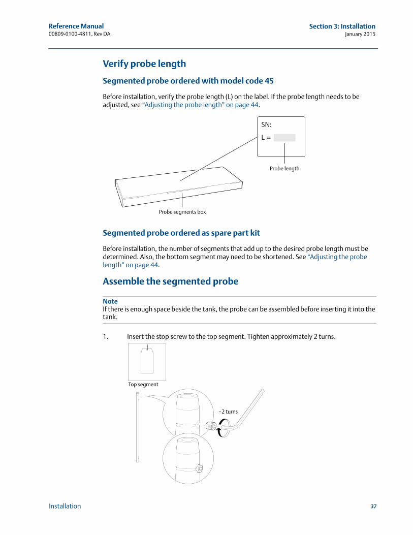
Verify probe length
Segmented probe ordered with model code 4S
Before installation, verify the probe length (L) on the label. If the probe length needs to be adjusted, see “Adjusting the probe length” on page 44.
Segmented probe ordered as spare part kit
Before installation, the number of segments that add up to the desired probe length must be determined. Also, the bottom segment may need to be shortened. See “Adjusting the probe length” on page 44.
Assemble the segmented probe
NoteIf there is enough space beside the tank, the probe can be assembled before inserting it into the tank.
1. Insert the stop screw to the top segment. Tighten approximately 2 turns.
L =
SN:
Probe length
Probe segments box
Top segment
~2 turns
37Installation
Reference Manual00809-0100-4811, Rev DA
Section 3: InstallationJanuary 2015
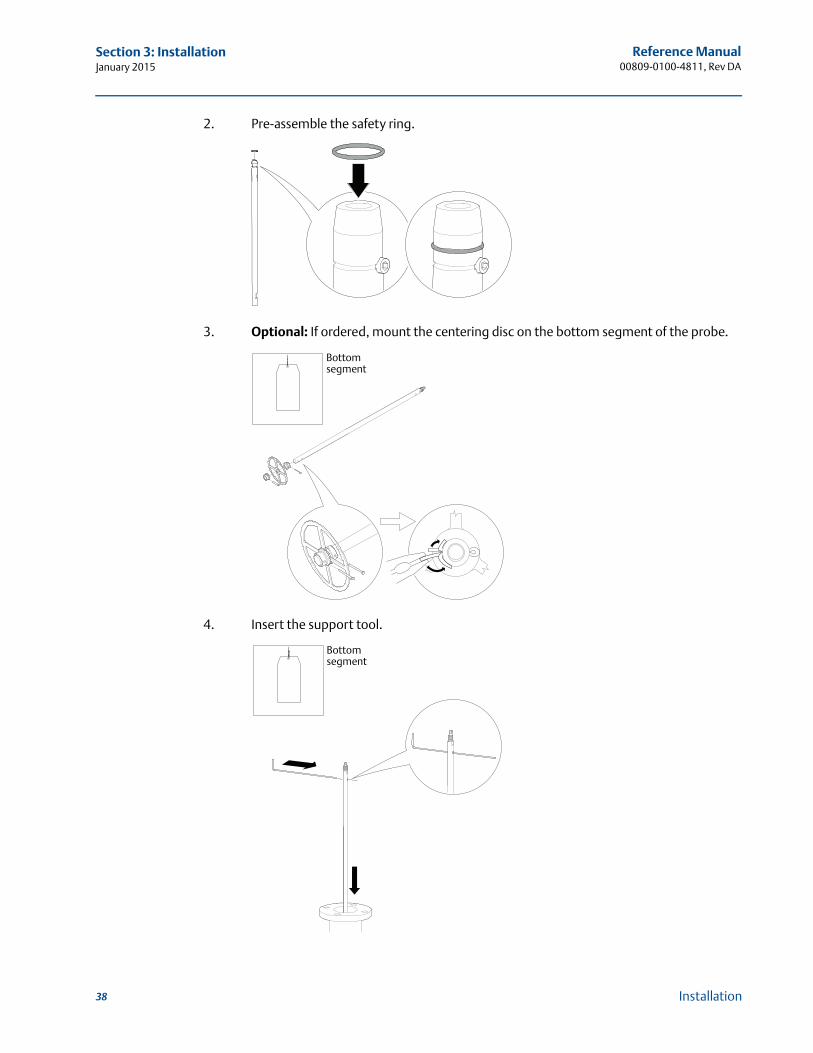
2. Pre-assemble the safety ring.
3. Optional: If ordered, mount the centering disc on the bottom segment of the probe.
4. Insert the support tool.
Bottom segment
Bottom segment
38 Installation
Reference Manual 00809-0100-4811, Rev DA
Section 3: InstallationJanuary 2015
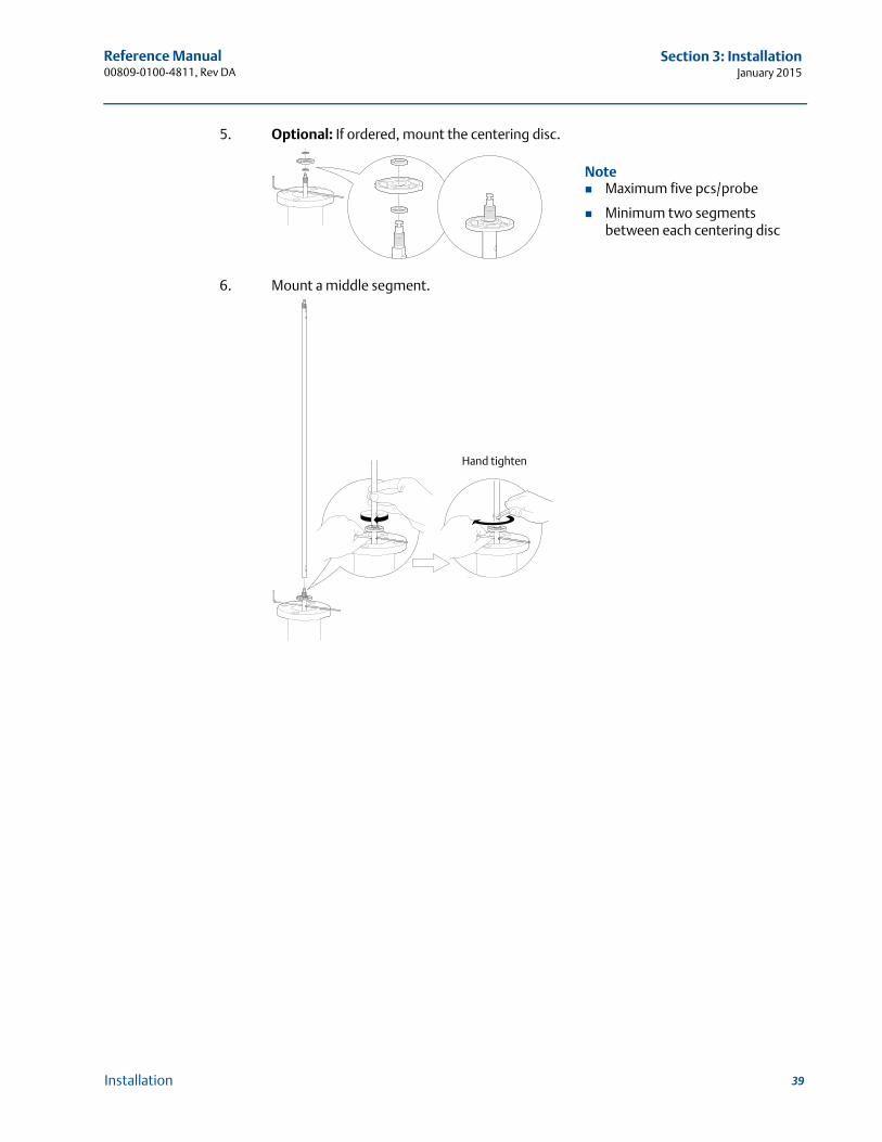
5. Optional: If ordered, mount the centering disc.
6. Mount a middle segment.
Note Maximum five pcs/probe
Minimum two segments between each centering disc
Hand tighten
39Installation
Reference Manual00809-0100-4811, Rev DA
Section 3: InstallationJanuary 2015
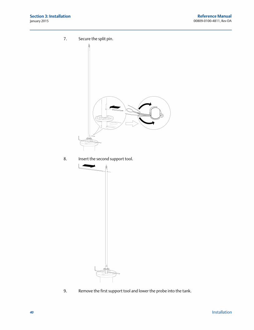
7. Secure the split pin.
8. Insert the second support tool.
9. Remove the first support tool and lower the probe into the tank.
40 Installation
Reference Manual 00809-0100-4811, Rev DA
Section 3: InstallationJanuary 2015
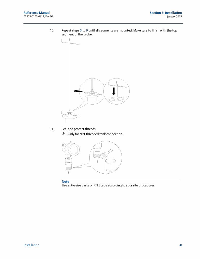
10. Repeat steps 5 to 9 until all segments are mounted. Make sure to finish with the top segment of the probe.
11. Seal and protect threads.
Only for NPT threaded tank connection.
NoteUse anti-seize paste or PTFE tape according to your site procedures.
41Installation
Reference Manual00809-0100-4811, Rev DA
Section 3: InstallationJanuary 2015
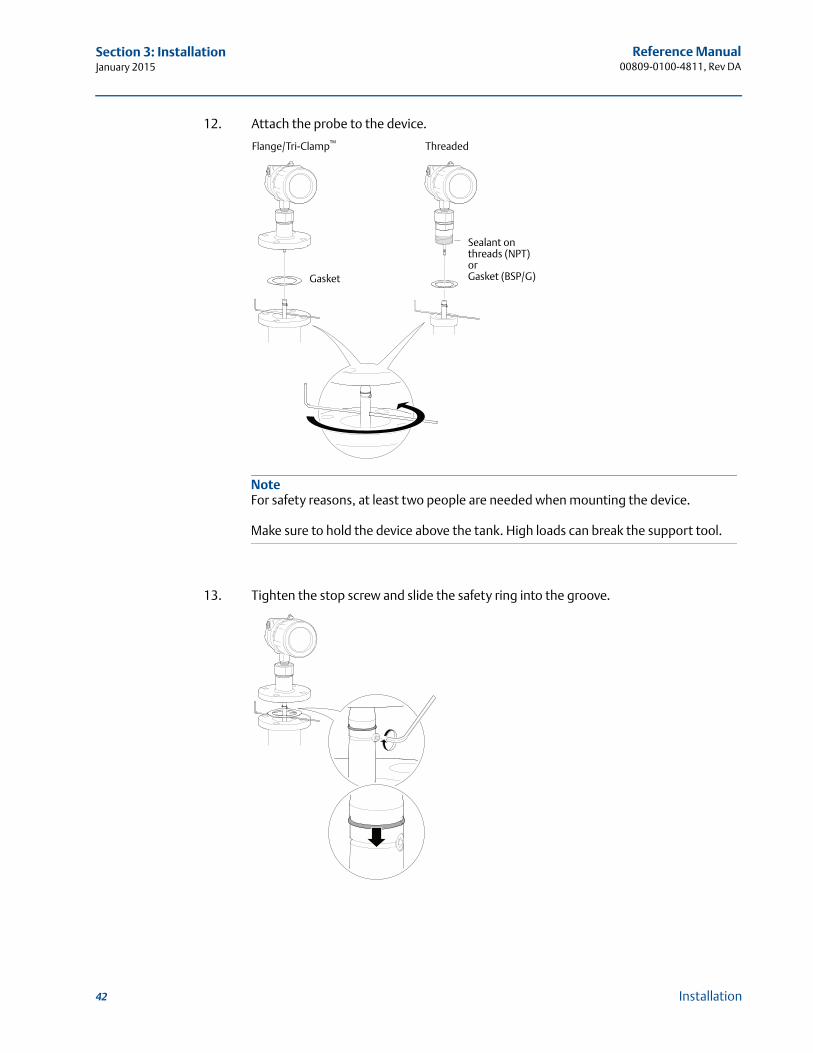
12. Attach the probe to the device.
13. Tighten the stop screw and slide the safety ring into the groove.
Flange/Tri-Clamp™ Threaded
Sealant on threads (NPT)or Gasket (BSP/G)Gasket
NoteFor safety reasons, at least two people are needed when mounting the device.
Make sure to hold the device above the tank. High loads can break the support tool.
42 Installation
Reference Manual 00809-0100-4811, Rev DA
Section 3: InstallationJanuary 2015
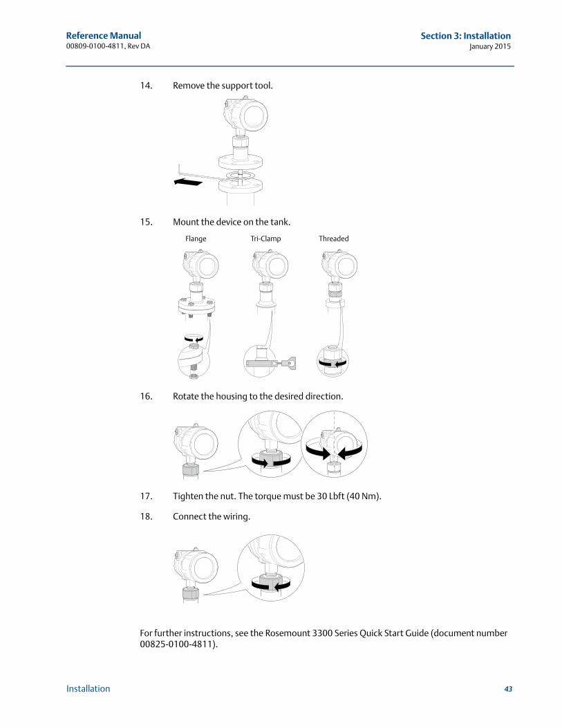
14. Remove the support tool.
15. Mount the device on the tank.
16. Rotate the housing to the desired direction.
17. Tighten the nut. The torque must be 30 Lbft (40 Nm).
18. Connect the wiring.
For further instructions, see the Rosemount 3300 Series Quick Start Guide (document number 00825-0100-4811).
Flange Tri-Clamp Threaded
43Installation
Reference Manual00809-0100-4811, Rev DA
Section 3: InstallationJanuary 2015
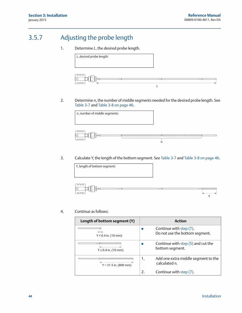
3.5.7 Adjusting the probe length
1. Determine L, the desired probe length.
2. Determine n, the number of middle segments needed for the desired probe length. See Table 3-7 and Table 3-8 on page 46.
3. Calculate Y, the length of the bottom segment. See Table 3-7 and Table 3-8 on page 46.
4. Continue as follows:
Length of bottom segment (Y) Action
Continue with step (7). Do not use the bottom segment.
Continue with step (5) and cut the bottom segment.
1. Add one extra middle segment to the calculated n.
2. Continue with step (7).
L, desired probe length:
L
n, number of middle segments:
n
Y, length of bottom segment:
Y
Y < 0.4 in. (10 mm)
Y ≥ 0.4 in. (10 mm)
Y = 31.5 in. (800 mm)
44 Installation
Reference Manual 00809-0100-4811, Rev DA
Section 3: InstallationJanuary 2015
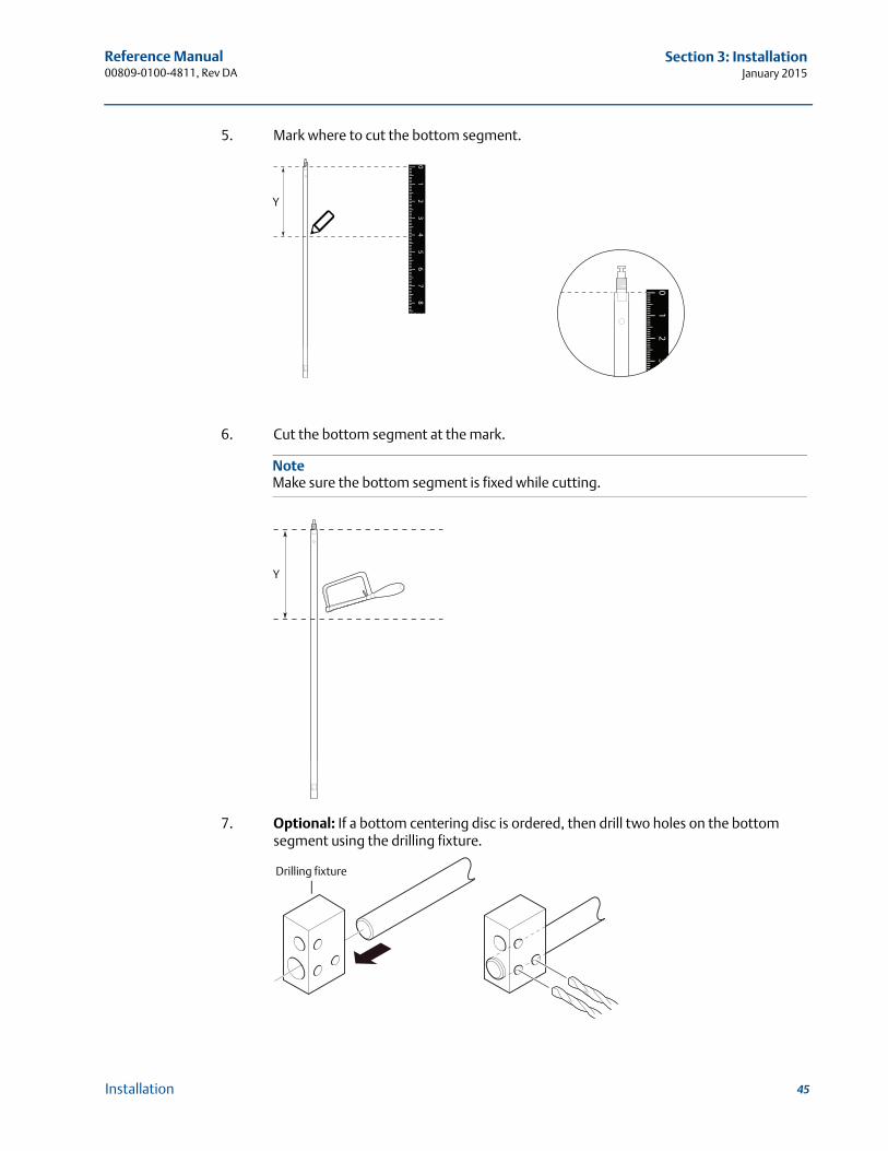
5. Mark where to cut the bottom segment.
6. Cut the bottom segment at the mark.
7. Optional: If a bottom centering disc is ordered, then drill two holes on the bottom segment using the drilling fixture.
12
34
56
78
0
12
30
Y
NoteMake sure the bottom segment is fixed while cutting.
Y
Drilling fixture
45Installation
Reference Manual00809-0100-4811, Rev DA
Section 3: InstallationJanuary 2015
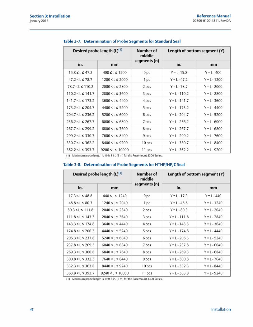
Table 3-7. Determination of Probe Segments for Standard Seal
Desired probe length (L)(1)
(1) Maximum probe length is 19 ft 8 in. (6 m) for the Rosemount 3300 Series.
Number of middle
segments (n)
Length of bottom segment (Y)
in. mm in. mm
15.8 ≤ L ≤ 47.2 400 ≤ L ≤ 1200 0 pc Y = L -15.8 Y = L - 400
47.2 < L ≤ 78.7 1200 < L ≤ 2000 1 pc Y = L - 47.2 Y = L - 1200
78.7 < L ≤ 110.2 2000 < L ≤ 2800 2 pcs Y = L - 78.7 Y = L - 2000
110.2 < L ≤ 141.7 2800 < L ≤ 3600 3 pcs Y = L - 110.2 Y = L - 2800
141.7 < L ≤ 173.2 3600 < L ≤ 4400 4 pcs Y = L - 141.7 Y = L - 3600
173.2 < L ≤ 204.7 4400 < L ≤ 5200 5 pcs Y = L - 173.2 Y = L - 4400
204.7 < L ≤ 236.2 5200 < L ≤ 6000 6 pcs Y = L - 204.7 Y = L - 5200
236.2 < L ≤ 267.7 6000 < L ≤ 6800 7 pcs Y = L - 236.2 Y = L - 6000
267.7 < L ≤ 299.2 6800 < L ≤ 7600 8 pcs Y = L - 267.7 Y = L - 6800
299.2 < L ≤ 330.7 7600 < L ≤ 8400 9 pcs Y = L - 299.2 Y = L - 7600
330.7 < L ≤ 362.2 8400 < L ≤ 9200 10 pcs Y = L - 330.7 Y = L - 8400
362.2 < L ≤ 393.7 9200 < L ≤ 10000 11 pcs Y = L - 362.2 Y = L - 9200
Table 3-8. Determination of Probe Segments for HTHP/HP/C Seal
Desired probe length (L)(1)
(1) Maximum probe length is 19 ft 8 in. (6 m) for the Rosemount 3300 Series.
Number of middle
segments (n)
Length of bottom segment (Y)
in. mm in. mm
17.3 ≤ L ≤ 48.8 440 ≤ L ≤ 1240 0 pc Y = L - 17.3 Y = L - 440
48.8 < L ≤ 80.3 1240 < L ≤ 2040 1 pc Y = L - 48.8 Y = L - 1240
80.3 < L ≤ 111.8 2040 < L ≤ 2840 2 pcs Y = L - 80.3 Y = L - 2040
111.8 < L ≤ 143.3 2840 < L ≤ 3640 3 pcs Y = L - 111.8 Y = L - 2840
143.3 < L ≤ 174.8 3640 < L ≤ 4440 4 pcs Y = L - 143.3 Y = L - 3640
174.8 < L ≤ 206.3 4440 < L ≤ 5240 5 pcs Y = L - 174.8 Y = L - 4440
206.3 < L ≤ 237.8 5240 < L ≤ 6040 6 pcs Y = L - 206.3 Y = L - 5240
237.8 < L ≤ 269.3 6040 < L ≤ 6840 7 pcs Y = L - 237.8 Y = L - 6040
269.3 < L ≤ 300.8 6840 < L ≤ 7640 8 pcs Y = L - 269.3 Y = L - 6840
300.8 < L ≤ 332.3 7640 < L ≤ 8440 9 pcs Y = L - 300.8 Y = L - 7640
332.3 < L ≤ 363.8 8440 < L ≤ 9240 10 pcs Y = L - 332.3 Y = L - 8440
363.8 < L ≤ 393.7 9240 < L ≤ 10000 11 pcs Y = L - 363.8 Y = L - 9240
46 Installation
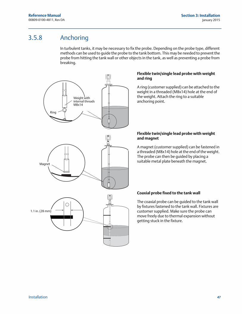
Reference Manual 00809-0100-4811, Rev DA
Section 3: InstallationJanuary 2015
3.5.8 Anchoring
In turbulent tanks, it may be necessary to fix the probe. Depending on the probe type, different methods can be used to guide the probe to the tank bottom. This may be needed to prevent the probe from hitting the tank wall or other objects in the tank, as well as preventing a probe from breaking.
Flexible twin/single lead probe with weight and ring
A ring (customer supplied) can be attached to the weight in a threaded (M8x14) hole at the end of the weight. Attach the ring to a suitable anchoring point.
Flexible twin/single lead probe with weight and magnet
A magnet (customer supplied) can be fastened in a threaded (M8x14) hole at the end of the weight. The probe can then be guided by placing a suitable metal plate beneath the magnet.
Coaxial probe fixed to the tank wall
The coaxial probe can be guided to the tank wall by fixtures fastened to the tank wall. Fixtures are customer supplied. Make sure the probe can move freely due to thermal expansion without getting stuck in the fixture.
Weight with internal threadsM8x14
Ring
Magnet
1.1 in. (28 mm)
47Installation
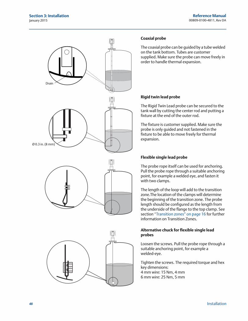
Reference Manual00809-0100-4811, Rev DA
Section 3: InstallationJanuary 2015
Coaxial probe
The coaxial probe can be guided by a tube welded on the tank bottom. Tubes are customer supplied. Make sure the probe can move freely in order to handle thermal expansion.
Rigid twin lead probe
The Rigid Twin Lead probe can be secured to the tank wall by cutting the center rod and putting a fixture at the end of the outer rod.
The fixture is customer supplied. Make sure the probe is only guided and not fastened in the fixture to be able to move freely for thermal expansion.
Flexible single lead probe
The probe rope itself can be used for anchoring. Pull the probe rope through a suitable anchoring point, for example a welded eye, and fasten it with two clamps.
The length of the loop will add to the transition zone.The location of the clamps will determine the beginning of the transition zone. The probe length should be configured as the length from the underside of the flange to the top clamp. See section “Transition zones” on page 16 for further information on Transition Zones.
Alternative chuck for flexible single lead probes
Loosen the screws. Pull the probe rope through a suitable anchoring point, for example a welded-eye.
Tighten the screws. The required torque and hex key dimensions:4 mm wire: 15 Nm, 4 mm6 mm wire: 25 Nm, 5 mm
Drain
Ø 0.3 in. (8 mm)
48 Installation
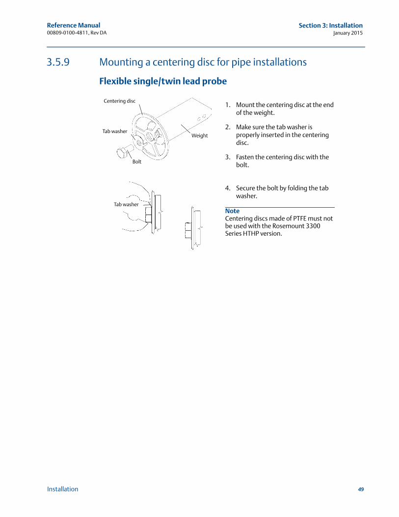
Reference Manual 00809-0100-4811, Rev DA
Section 3: InstallationJanuary 2015
3.5.9 Mounting a centering disc for pipe installations
Flexible single/twin lead probe
1. Mount the centering disc at the end of the weight.
2. Make sure the tab washer is properly inserted in the centering disc.
3. Fasten the centering disc with the bolt.
4. Secure the bolt by folding the tab washer.
NoteCentering discs made of PTFE must not be used with the Rosemount 3300 Series HTHP version.
Centering disc
Weight
Bolt
Tab washer
Tab washer
49Installation
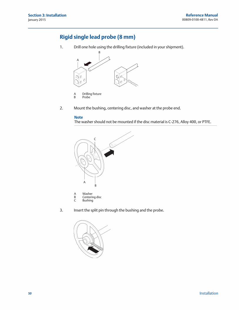
Reference Manual00809-0100-4811, Rev DA
Section 3: InstallationJanuary 2015
Rigid single lead probe (8 mm)
1. Drill one hole using the drilling fixture (included in your shipment).
2. Mount the bushing, centering disc, and washer at the probe end.
3. Insert the split pin through the bushing and the probe.
A Drilling fixtureB Probe
A
B
NoteThe washer should not be mounted if the disc material is C-276, Alloy 400, or PTFE.
AB
C
A WasherB Centering discC Bushing
50 Installation
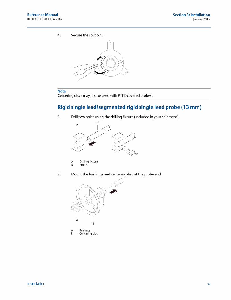
Reference Manual 00809-0100-4811, Rev DA
Section 3: InstallationJanuary 2015
4. Secure the split pin.
NoteCentering discs may not be used with PTFE-covered probes.
Rigid single lead/segmented rigid single lead probe (13 mm)
1. Drill two holes using the drilling fixture (included in your shipment).
2. Mount the bushings and centering disc at the probe end.
AB
A Drilling fixtureB Probe
AB
A
A BushingB Centering disc
51Installation

Reference Manual00809-0100-4811, Rev DA
Section 3: InstallationJanuary 2015
3. Adjust distance by shifting hole for split pin in lower bushing.
4. Insert the split pins through the bushings and the probe.
5. Secure the split pins.
3.6 Electrical installation
3.6.1 Cable/conduit entries
The electronics housing has two entries for ½ - 14 NPT. Optional M20×1.5 and PG 13.5 adapters are also available. The connections are made in accordance with local or plant electrical codes.
Make sure unused ports are properly sealed to prevent moisture or other contamination from entering the terminal block compartment of the electronics housing.
NoteRemove any orange caps that may be attached. Use the enclosed metal plug to seal the unused port.
3.6.2 Grounding
The housing should always be grounded in accordance with national and local electrical codes. Failure to do so may impair the protection provided by the equipment. The most effective grounding method is direct connection to earth ground with minimal impedance. There are
0.16 in. (4 mm)
0.08 in. (2 mm)
52 Installation
Reference Manual 00809-0100-4811, Rev DA
Section 3: InstallationJanuary 2015
two grounding screw connections provided. One is inside the Field Terminal side of the housing and the other is located on top of the housing. The internal ground screw is identified by a
ground symbol: .
NoteGrounding the transmitter via threaded conduit connection may not provide sufficient ground.
NoteIn the Explosion-proof/Flameproof version the electronics is grounded via the transmitter housing. After installation and commissioning make sure that no ground currents exist due to high ground potential differences in the installation.
3.6.3 Cable selection
Use shielded twisted pair wiring for the Rosemount 3300 Series in order to comply with EMC regulations. The cables must be suitable for the supply voltage and approved for use in hazardous areas, where applicable. For instance, in the U.S., explosion-proof conduits must be used in the vicinity of the vessel. For the ATEX flameproof approval version of the Rosemount 3300 Series, suitable conduits with sealing device or flameproof (EEx d) cable glands must be used depending on local requirements.
Use 18 AWG to 12 AWG in order to minimize the voltage drop to the transmitter.
3.6.4 Hazardous areas
When the Rosemount 3300 Series Transmitter is installed in hazardous areas, local regulations and specifications in applicable certificates must be observed.
3.6.5 HART
Power requirements
Terminals in the transmitter housing provide connections for signal cables.
The Rosemount 3300 Series Transmitter is loop-powered and operates with power supplies ranging from 11 to 42 Vdc. For Intrinsically Safe output, the supply voltage must be within 11 to 30 Vdc. For explosion-proof/flameproof the supply voltage must be within 16 and 42 Vdc.
Maximum loop resistance
The maximum current loop resistance can be gained from the following diagrams:
53Installation
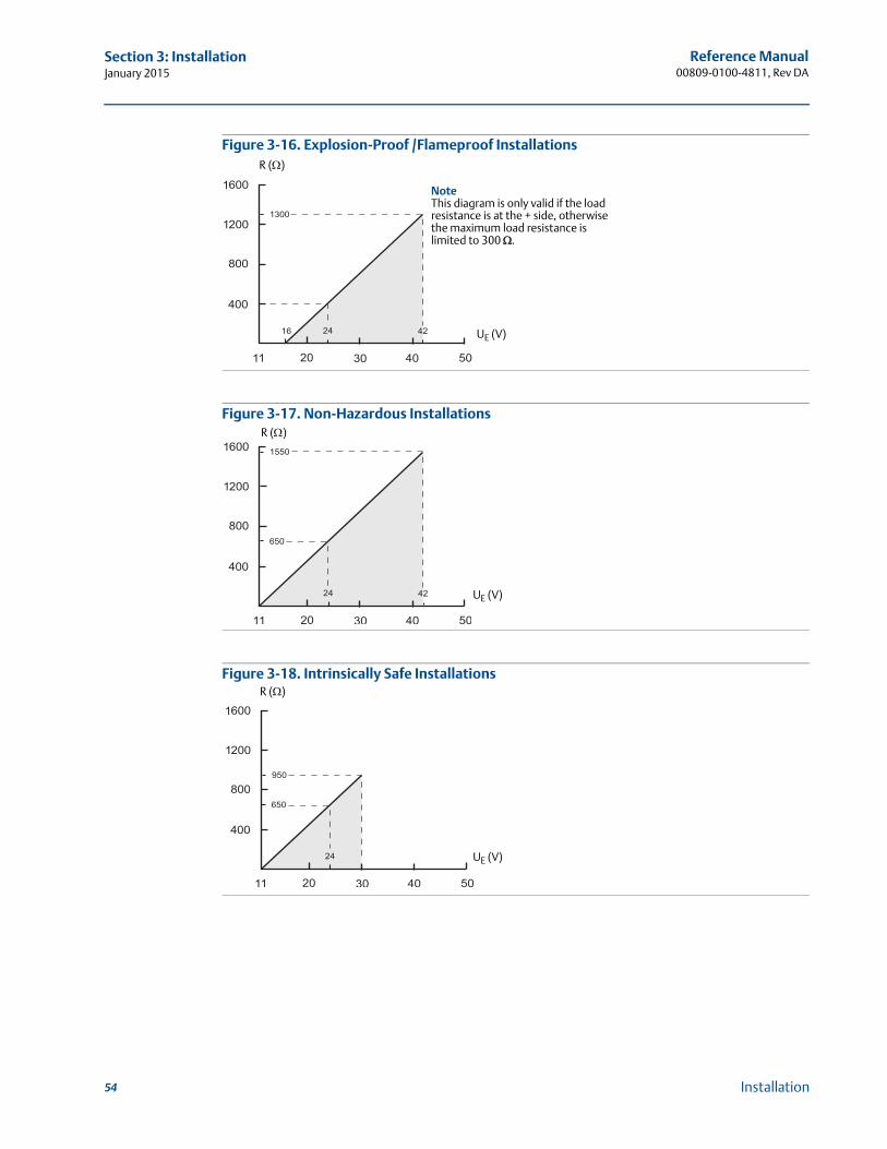
Reference Manual00809-0100-4811, Rev DA
Section 3: InstallationJanuary 2015
Figure 3-16. Explosion-Proof /Flameproof Installations
Figure 3-17. Non-Hazardous Installations
Figure 3-18. Intrinsically Safe Installations
NoteThis diagram is only valid if the load resistance is at the + side, otherwise the maximum load resistance is limited to 300 .
R ()
UE (V)
R ()
UE (V)
UE (V)
R ()
54 Installation
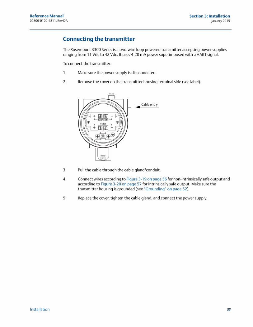
Reference Manual 00809-0100-4811, Rev DA
Section 3: InstallationJanuary 2015
Connecting the transmitter
The Rosemount 3300 Series is a two-wire loop powered transmitter accepting power supplies ranging from 11 Vdc to 42 Vdc. It uses 4-20 mA power superimposed with a HART signal.
To connect the transmitter:
1. Make sure the power supply is disconnected.
2. Remove the cover on the transmitter housing terminal side (see label).
3. Pull the cable through the cable gland/conduit.
4. Connect wires according to Figure 3-19 on page 56 for non-intrinsically safe output and according to Figure 3-20 on page 57 for Intrinsically safe output. Make sure the transmitter housing is grounded (see “Grounding” on page 52).
5. Replace the cover, tighten the cable gland, and connect the power supply.
Cable entry
55Installation
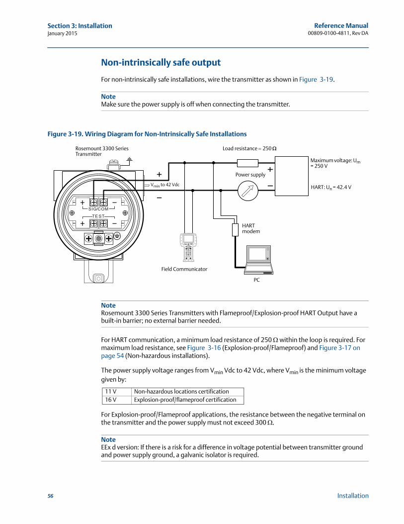
Reference Manual00809-0100-4811, Rev DA
Section 3: InstallationJanuary 2015
Non-intrinsically safe output
For non-intrinsically safe installations, wire the transmitter as shown in Figure 3-19.
NoteMake sure the power supply is off when connecting the transmitter.
Figure 3-19. Wiring Diagram for Non-Intrinsically Safe Installations
NoteRosemount 3300 Series Transmitters with Flameproof/Explosion-proof HART Output have a built-in barrier; no external barrier needed.
For HART communication, a minimum load resistance of 250 within the loop is required. For maximum load resistance, see Figure 3-16 (Explosion-proof/Flameproof) and Figure 3-17 on page 54 (Non-hazardous installations).
The power supply voltage ranges from Vmin Vdc to 42 Vdc, where Vmin is the minimum voltage given by:
For Explosion-proof/Flameproof applications, the resistance between the negative terminal on the transmitter and the power supply must not exceed 300 .
NoteEEx d version: If there is a risk for a difference in voltage potential between transmitter ground and power supply ground, a galvanic isolator is required.
11 V Non-hazardous locations certification16 V Explosion-proof/flameproof certification
Load resistance 250
Power supply
HARTmodem
Field Communicator
PC
Rosemount 3300 Series Transmitter
Maximum voltage: Um = 250 V
HART: Un = 42.4 VVmin to 42 Vdc
56 Installation
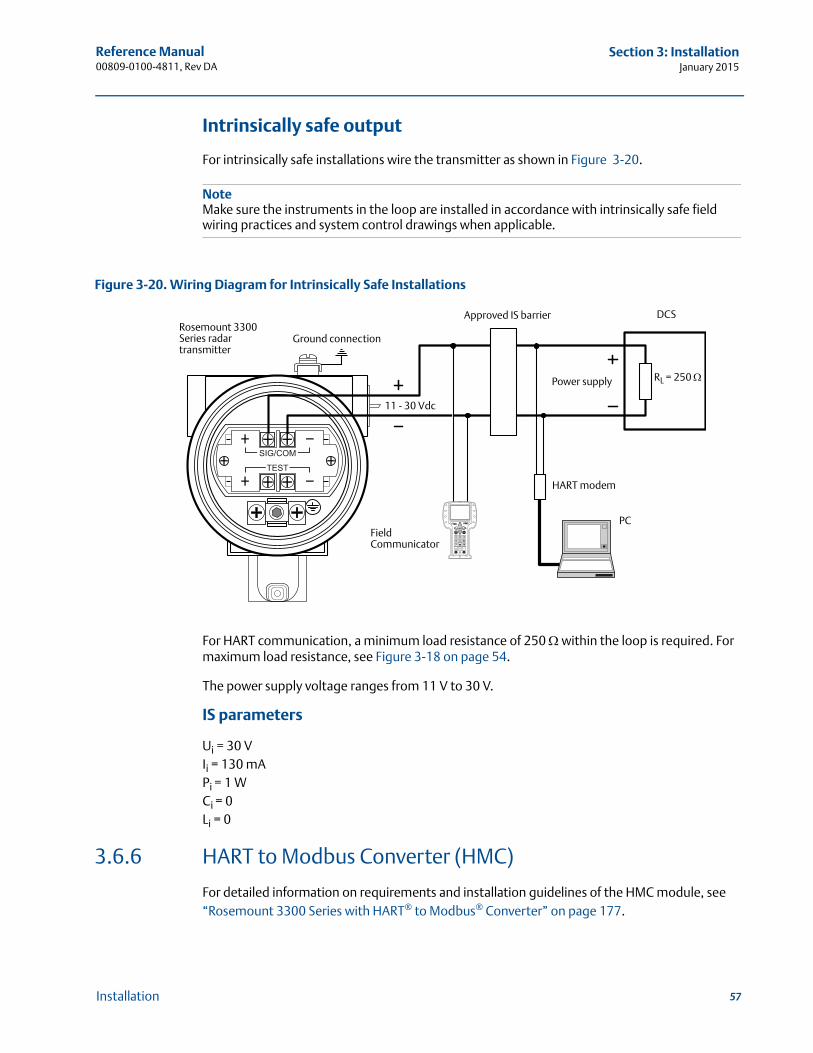
Reference Manual 00809-0100-4811, Rev DA
Section 3: InstallationJanuary 2015
Intrinsically safe output
For intrinsically safe installations wire the transmitter as shown in Figure 3-20.
NoteMake sure the instruments in the loop are installed in accordance with intrinsically safe field wiring practices and system control drawings when applicable.
Figure 3-20. Wiring Diagram for Intrinsically Safe Installations
For HART communication, a minimum load resistance of 250 within the loop is required. For maximum load resistance, see Figure 3-18 on page 54.
The power supply voltage ranges from 11 V to 30 V.
IS parameters
Ui = 30 VIi = 130 mAPi = 1 WCi = 0Li = 0
3.6.6 HART to Modbus Converter (HMC)
For detailed information on requirements and installation guidelines of the HMC module, see “Rosemount 3300 Series with HART® to Modbus® Converter” on page 177.
DCS
RL = 250
Approved IS barrier
Field Communicator
HART modem
PC
Power supply
Rosemount 3300 Series radar transmitter
11 - 30 Vdc
Ground connection
57Installation
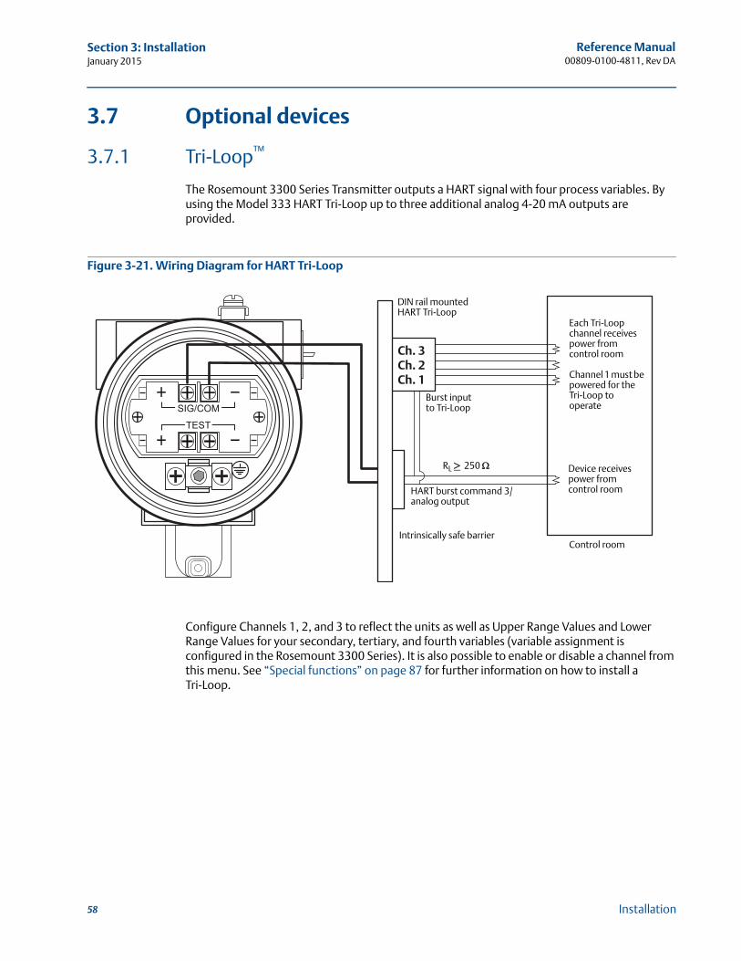
Reference Manual00809-0100-4811, Rev DA
Section 3: InstallationJanuary 2015
3.7 Optional devices
3.7.1 Tri-Loop™
The Rosemount 3300 Series Transmitter outputs a HART signal with four process variables. By using the Model 333 HART Tri-Loop up to three additional analog 4-20 mA outputs are provided.
Figure 3-21. Wiring Diagram for HART Tri-Loop
Configure Channels 1, 2, and 3 to reflect the units as well as Upper Range Values and Lower Range Values for your secondary, tertiary, and fourth variables (variable assignment is configured in the Rosemount 3300 Series). It is also possible to enable or disable a channel from this menu. See “Special functions” on page 87 for further information on how to install a Tri-Loop.
Ch. 3Ch. 2Ch. 1
Each Tri-Loop channel receives power from control room
Channel 1 must be powered for the Tri-Loop to operate
Device receives power from control room
RL 250
HART burst command 3/analog output
Intrinsically safe barrier
DIN rail mountedHART Tri-Loop
Control room
Burst input to Tri-Loop
58 Installation
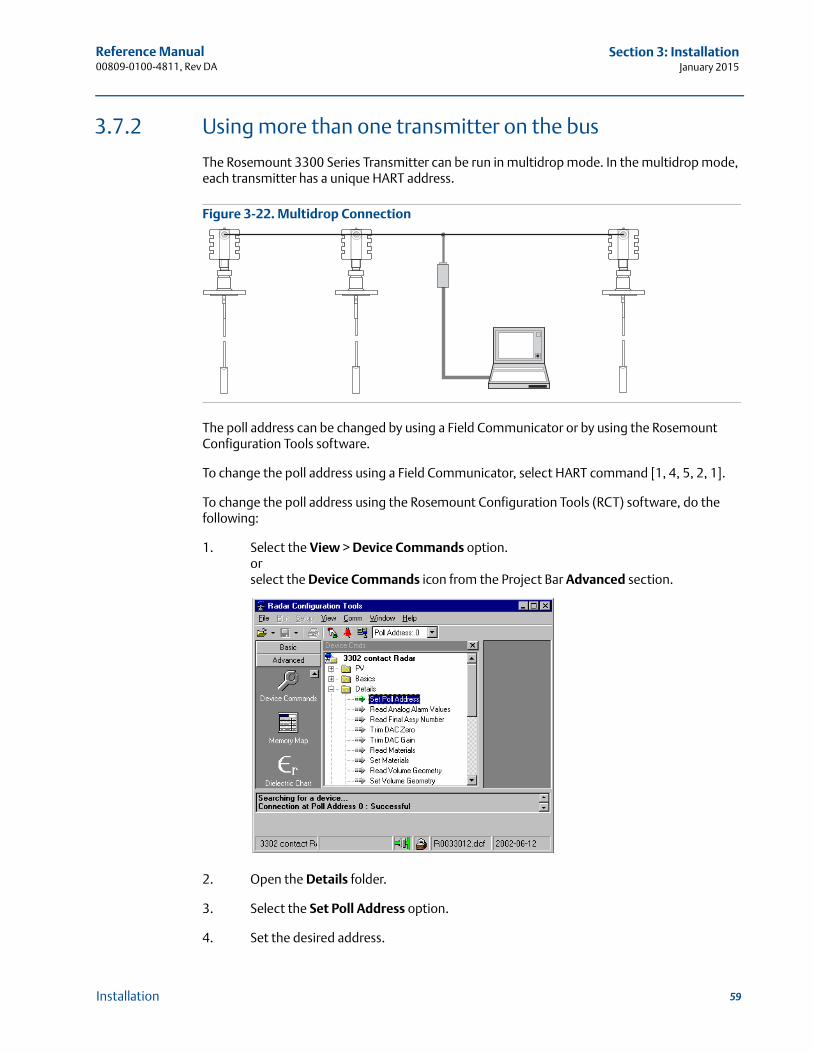
Reference Manual 00809-0100-4811, Rev DA
Section 3: InstallationJanuary 2015
3.7.2 Using more than one transmitter on the bus
The Rosemount 3300 Series Transmitter can be run in multidrop mode. In the multidrop mode, each transmitter has a unique HART address.
Figure 3-22. Multidrop Connection
The poll address can be changed by using a Field Communicator or by using the Rosemount Configuration Tools software.
To change the poll address using a Field Communicator, select HART command [1, 4, 5, 2, 1].
To change the poll address using the Rosemount Configuration Tools (RCT) software, do the following:
1. Select the View > Device Commands option.orselect the Device Commands icon from the Project Bar Advanced section.
2. Open the Details folder.
3. Select the Set Poll Address option.
4. Set the desired address.
59Installation
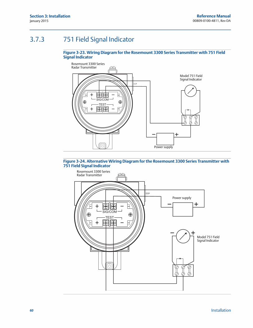
Reference Manual00809-0100-4811, Rev DA
Section 3: InstallationJanuary 2015
3.7.3 751 Field Signal Indicator
Figure 3-23. Wiring Diagram for the Rosemount 3300 Series Transmitter with 751 Field Signal Indicator
Figure 3-24. Alternative Wiring Diagram for the Rosemount 3300 Series Transmitter with 751 Field Signal Indicator
Power supply
Rosemount 3300 Series Radar Transmitter
Model 751 Field Signal Indicator
Power supply
Model 751 Field Signal Indicator
Rosemount 3300 Series Radar Transmitter
60 Installation
Reference Manual 00809-0100-4811, Rev DA
Section 4: Basic Configuration/Start-UpJanuary 2015
Section 4 Basic Configuration/Start-Up
Safety messages . . . . . . . . . . . . . . . . . . . . . . . . . . . . . . . . . . . . . . . . . . . . . . . . . . . . . . . . . . . . 61Configuration parameters . . . . . . . . . . . . . . . . . . . . . . . . . . . . . . . . . . . . . . . . . . . . . . . . . . . . 62Configuration using a Field Communicator . . . . . . . . . . . . . . . . . . . . . . . . . . . . . . . . . . . . . 67Basic configuration . . . . . . . . . . . . . . . . . . . . . . . . . . . . . . . . . . . . . . . . . . . . . . . . . . . . . . . . . . 69Volume configuration . . . . . . . . . . . . . . . . . . . . . . . . . . . . . . . . . . . . . . . . . . . . . . . . . . . . . . . 74Configuration using the Radar Configuration Tool . . . . . . . . . . . . . . . . . . . . . . . . . . . . . . . 75Special functions . . . . . . . . . . . . . . . . . . . . . . . . . . . . . . . . . . . . . . . . . . . . . . . . . . . . . . . . . . . 87
4.1 Safety messages
Procedures and instructions in this section may require special precautions to ensure the safety of the personnel performing the operations. Information that raises potential safety issues is
indicated by a warning symbol ( ). Refer to the safety messages listed at the beginning of each section before performing an operation preceded by this symbol.
Failure to follow safe installation and servicing guidelines could result in death or serious injury.
Make sure only qualified personnel perform the installation. Use the equipment only as specified in this manual. Failure to do so may impair the
protection provided by the equipment. Do not perform any service other than those contained in this manual unless you are
qualified.
61Basic Configuration/Start-Up

Reference Manual00809-0100-4811, Rev DA
Section 4: Basic Configuration/Start-UpJanuary 2015
4.2 Configuration parameters
The Rosemount 3301 Transmitter can be configured for level and volume measurements. The Rosemount 3302 is designed to measure interface level and interface distance as well.
The Rosemount 3300 Series Transmitters can be pre-configured according to the ordering specifications in the Configuration Data Sheet.
4.2.1 Basic configuration
The basic transmitter configuration includes setting the tank geometry parameters. For interface measurements, the dielectric constant of the top liquid must also be given. For some applications with heavy vapor, the vapor dielectric must be given as well.
Figure 4-1. Tank Geometry
For the different tank connections, the upper reference point is located at the underside of the threaded adapter or at the underside of the welded flange, as illustrated in Figure 4-2:
Figure 4-2. Upper Reference Point
4mA
20mA
Reference gauge height
UNZ
Product level
Upper reference point
Lower reference point
Interface level
Probe length
NPT BSP (G) Flange
Upper reference point
Adapter
Tri-Clamp™
62 Basic Configuration/Start-Up
Reference Manual 00809-0100-4811, Rev DA
Section 4: Basic Configuration/Start-UpJanuary 2015
Reference gauge height
The reference gauge height is the distance from the upper reference point to the bottom of the tank. The transmitter measures the distance to the product surface and subtracts this value from the reference gauge height to determine the level.
Probe length
The probe length is the distance between the upper reference point and the end of the probe. If a weight is used at the end of the probe it should not be included.
For flexible single lead probes anchored with clamps, the probe length should be configured as the distance between the underside of the flange and the upper clamp (see Using a segmented probe on page 36).
This parameter is pre-configured at factory. It must be changed if the probe is shortened.
Probe type
The transmitter is designed to optimize measurement performance for each probe type.
This parameter is pre-configured at factory. This value needs to be changed if the probe type is changed.
Flexible and rigid probes require different radar electronics and cannot be used with the same transmitter head.
Dielectric constant of upper product
For interface measurements, the dielectric constant of the upper product is essential to obtain good accuracy. See Interface on page 12 for further information on dielectric constants.
If the dielectric constant of the lower product is significantly smaller than the dielectric constant of water, you may need to make special adjustments. See Interface measurements for semi-transparent bottom products on page 96 for further information.
For level measurements, the Upper Product Dielectric parameter corresponds to the actual dielectric constant of the product in the tank. Normally, this parameter does not need to be changed even if the actual dielectric constant of the product deviates from the Upper Product Dielectric parameter value. However, for some products, measurement performance can be optimized by setting the proper product dielectric constant.
Dielectric constant of vapor
In some applications, there is heavy vapor above the product surface having a significant influence on the level measurement. In such cases, the vapor dielectric can be entered to compensate for this effect.
The default value is equal to 1 which corresponds to the dielectricity of vacuum. Normally, this value does not need to be changed since the effect on measurement performance is very small for most vapors.
63Basic Configuration/Start-Up
Reference Manual00809-0100-4811, Rev DA
Section 4: Basic Configuration/Start-UpJanuary 2015
Upper null zone
This parameter should only be changed if there are measurement problems in the upper part of the tank. Such problems may occur if there are disturbing objects close to the probe. By setting the Upper Null Zone (UNZ), the measuring range is reduced. See Disturbances at the top of the tank on page 102 for further information.
NoteMeasurements are not performed within the UNZ.
4 mA point
The 4 mA point must be set above the lower transition zone (see Transition zones on page 16). If the 4 mA point is set to a point within the transition zone or below the probe end, the full range of the analog output is not used.
20 mA point
Make sure the 20 mA point is below the upper null zone.
The 20 mA point must be set below the upper transition zone (see Transition zones on page 16). If the 20 mA point is set to a point within the transition zone, the full range of the analog output is not used.
Probe angle
If the transmitter is not mounted vertically, the angle from the vertical position must be given.
4.2.2 Volume configuration
For volume calculations, you can select one of the standard tank shapes or the strapping option. Select None if volume calculation is not used.
Tank type
You can select one of the following options:
Strap table
Vertical cylinder
Horizontal cylinder
Vertical bullet
Horizontal bullet
Sphere
None
64 Basic Configuration/Start-Up
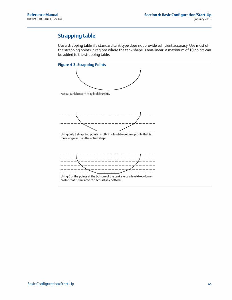
Reference Manual 00809-0100-4811, Rev DA
Section 4: Basic Configuration/Start-UpJanuary 2015
Strapping table
Use a strapping table if a standard tank type does not provide sufficient accuracy. Use most of the strapping points in regions where the tank shape is non-linear. A maximum of 10 points can be added to the strapping table.
Figure 4-3. Strapping Points
Actual tank bottom may look like this.
Using only 3 strapping points results in a level-to-volume profile that is more angular than the actual shape.
Using 6 of the points at the bottom of the tank yields a level-to-volume profile that is similar to the actual tank bottom.
65Basic Configuration/Start-Up
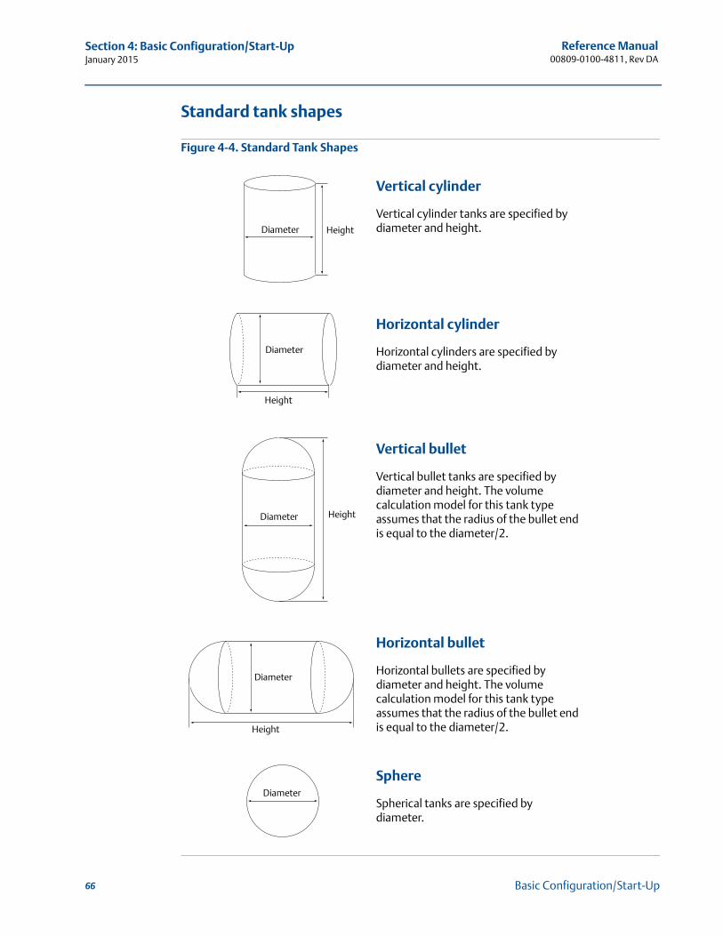
Reference Manual00809-0100-4811, Rev DA
Section 4: Basic Configuration/Start-UpJanuary 2015
Standard tank shapes
Figure 4-4. Standard Tank Shapes
Vertical cylinder
Vertical cylinder tanks are specified by diameter and height.
Horizontal cylinder
Horizontal cylinders are specified by diameter and height.
Vertical bullet
Vertical bullet tanks are specified by diameter and height. The volume calculation model for this tank type assumes that the radius of the bullet end is equal to the diameter/2.
Horizontal bullet
Horizontal bullets are specified by diameter and height. The volume calculation model for this tank type assumes that the radius of the bullet end is equal to the diameter/2.
Sphere
Spherical tanks are specified by diameter.
Diameter Height
Diameter
Height
Diameter Height
Diameter
Height
Diameter
66 Basic Configuration/Start-Up

Reference Manual 00809-0100-4811, Rev DA
Section 4: Basic Configuration/Start-UpJanuary 2015
4.3 Configuration using a Field Communicator
This section describes how to configure the Rosemount 3300 Series Transmitter by using a Field Communicator. A HART® communicator may also be used.
For information on all the capabilities, refer to the 375 Field Communicator User’s Manual or the 475 Field Communicator User’s Manual, available at www.fieldcommunicator.com.
Figure 4-5. 475 Field Communicator
F
E
C
D
B
A
A Enter keyB Tab keysC Alphanumeric keysD Backlight adjustment keyE Navigation keysF Function key
67Basic Configuration/Start-Up
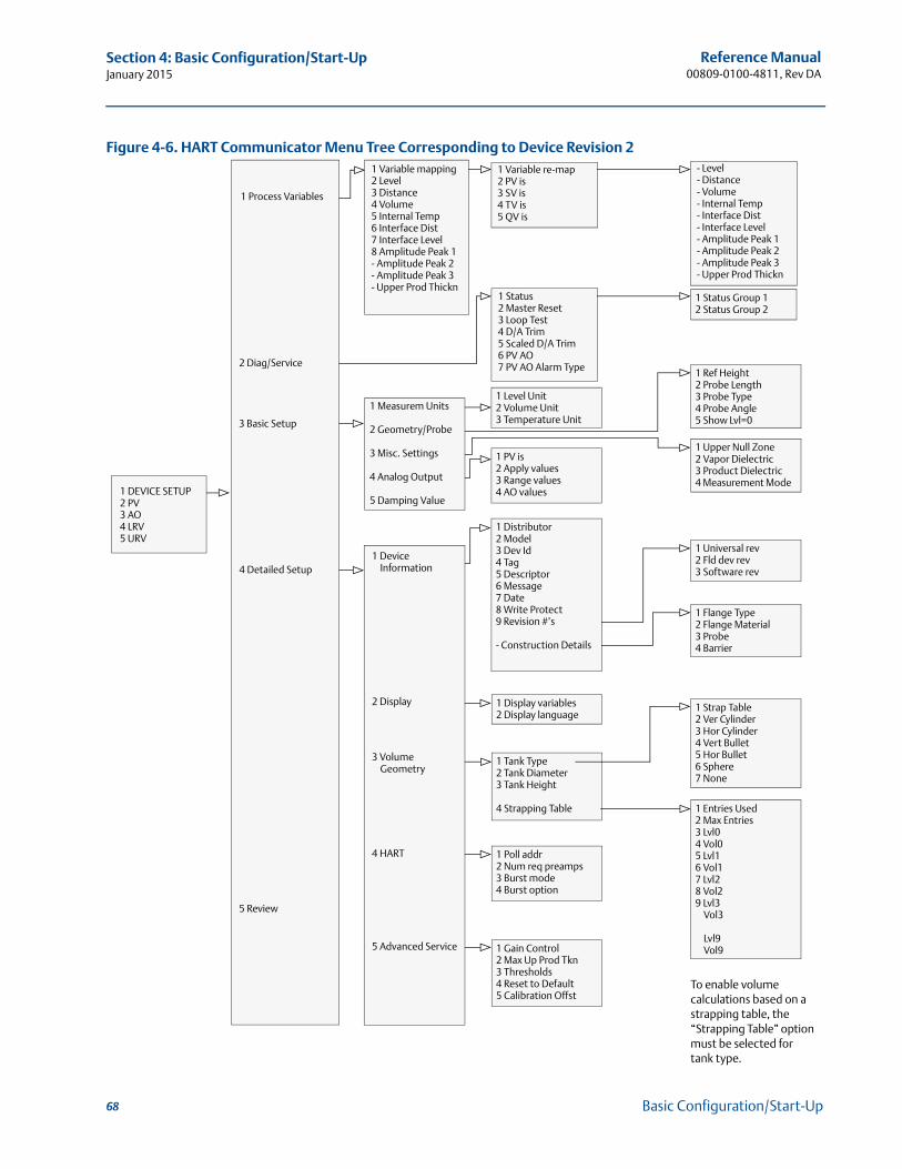
Reference Manual00809-0100-4811, Rev DA
Section 4: Basic Configuration/Start-UpJanuary 2015
Figure 4-6. HART Communicator Menu Tree Corresponding to Device Revision 2
1 DEVICE SETUP2 PV3 AO4 LRV5 URV
1 Process Variables
2 Diag/Service
3 Basic Setup
4 Detailed Setup
5 Review
1 Variable mapping2 Level3 Distance4 Volume5 Internal Temp6 Interface Dist7 Interface Level8 Amplitude Peak 1- Amplitude Peak 2- Amplitude Peak 3- Upper Prod Thickn
1 Measurem Units
2 Geometry/Probe
3 Misc. Settings
4 Analog Output
5 Damping Value
1 Device Information
2 Display
3 Volume Geometry
4 HART
5 Advanced Service
1 Variable re-map2 PV is3 SV is4 TV is5 QV is
1 Status2 Master Reset3 Loop Test4 D/A Trim5 Scaled D/A Trim6 PV AO7 PV AO Alarm Type
1 Level Unit2 Volume Unit3 Temperature Unit
1 PV is2 Apply values3 Range values4 AO values
1 Distributor2 Model3 Dev Id4 Tag5 Descriptor6 Message7 Date8 Write Protect9 Revision #’s
- Construction Details
1 Display variables2 Display language
1 Tank Type2 Tank Diameter3 Tank Height
4 Strapping Table
1 Poll addr2 Num req preamps3 Burst mode4 Burst option
1 Gain Control2 Max Up Prod Tkn3 Thresholds4 Reset to Default5 Calibration Offst
- Level- Distance- Volume- Internal Temp- Interface Dist- Interface Level- Amplitude Peak 1- Amplitude Peak 2- Amplitude Peak 3- Upper Prod Thickn
1 Status Group 12 Status Group 2
1 Ref Height2 Probe Length3 Probe Type4 Probe Angle5 Show Lvl=0
1 Upper Null Zone2 Vapor Dielectric3 Product Dielectric4 Measurement Mode
1 Universal rev2 Fld dev rev3 Software rev
1 Flange Type2 Flange Material3 Probe4 Barrier
1 Strap Table2 Ver Cylinder3 Hor Cylinder4 Vert Bullet5 Hor Bullet6 Sphere7 None
1 Entries Used2 Max Entries3 Lvl04 Vol05 Lvl16 Vol17 Lvl28 Vol29 Lvl3
Vol3
Lvl9Vol9
To enable volume calculations based on a strapping table, the “Strapping Table” option must be selected for tank type.
68 Basic Configuration/Start-Up
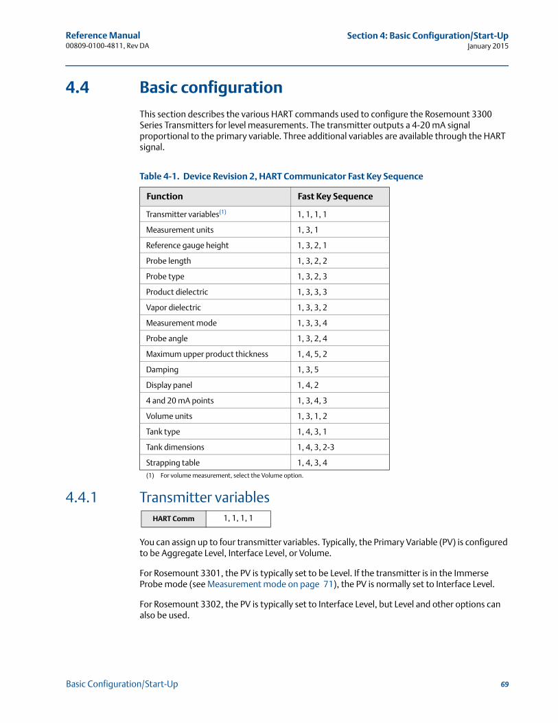
Reference Manual 00809-0100-4811, Rev DA
Section 4: Basic Configuration/Start-UpJanuary 2015
4.4 Basic configuration
This section describes the various HART commands used to configure the Rosemount 3300 Series Transmitters for level measurements. The transmitter outputs a 4-20 mA signal proportional to the primary variable. Three additional variables are available through the HART signal.
Table 4-1. Device Revision 2, HART Communicator Fast Key Sequence
4.4.1 Transmitter variables
You can assign up to four transmitter variables. Typically, the Primary Variable (PV) is configured to be Aggregate Level, Interface Level, or Volume.
For Rosemount 3301, the PV is typically set to be Level. If the transmitter is in the Immerse Probe mode (see Measurement mode on page 71), the PV is normally set to Interface Level.
For Rosemount 3302, the PV is typically set to Interface Level, but Level and other options can also be used.
Function Fast Key Sequence
Transmitter variables(1)
(1) For volume measurement, select the Volume option.
1, 1, 1, 1
Measurement units 1, 3, 1
Reference gauge height 1, 3, 2, 1
Probe length 1, 3, 2, 2
Probe type 1, 3, 2, 3
Product dielectric 1, 3, 3, 3
Vapor dielectric 1, 3, 3, 2
Measurement mode 1, 3, 3, 4
Probe angle 1, 3, 2, 4
Maximum upper product thickness 1, 4, 5, 2
Damping 1, 3, 5
Display panel 1, 4, 2
4 and 20 mA points 1, 3, 4, 3
Volume units 1, 3, 1, 2
Tank type 1, 4, 3, 1
Tank dimensions 1, 4, 3, 2-3
Strapping table 1, 4, 3, 4
HART Comm 1, 1, 1, 1
69Basic Configuration/Start-Up
Reference Manual00809-0100-4811, Rev DA
Section 4: Basic Configuration/Start-UpJanuary 2015
4.4.2 Measurement units
Set transmitter units for level and temperature.
4.4.3 Reference gauge height
The Reference Gauge Height is the distance from the Upper Reference Point to the bottom of the tank (see Figure 4-1 on page 62). When setting the Reference Gauge Height, keep in mind that this value is used for all level measurements performed by the Rosemount 3300 Series Transmitter.
The Reference Gauge Height must be set in linear (level) units, such as feet or meters, regardless of primary variable assignment.
4.4.4 Probe length
The probe length is the distance from the Upper Reference Point to the end of the probe, see Figure 4-1 on page 62. If the probe is anchored to a weight, do not include the height of the weight. This parameter is pre-configured at factory. The probe length needs to be changed if, for example, the probe is shortened.
4.4.5 Probe type
The transmitter automatically makes an initial calibration based on the type of probe that is used. This parameter is pre-configured at factory and only needs to be set if the probe is changed to another type. Select one of the following options:
Rigid Twin
Flexible Twin
Coaxial
Rigid Single 0.3 in. (8 mm)
Flexible Single
Coaxial HTHP
Coaxial HP/C
Rigid Single HTHP 0.3 in. (8 mm)
Flexible Single HTHP
Rigid Single PTFE
Flexible Single PTFE
Rigid Single HP/C 0.3 in. (8 mm)
Flexible Single HP/C 0.3 in. (8 mm)
HART Comm 1, 3, 1
HART Comm 1, 3, 2, 1
HART Comm 1, 3, 2, 2
HART Comm 1, 3, 2, 3
70 Basic Configuration/Start-Up
Reference Manual 00809-0100-4811, Rev DA
Section 4: Basic Configuration/Start-UpJanuary 2015
Flexible Single HP
Rigid Single 0.5 in. (13 mm)
User Defined
NoteFlexible and rigid probes require different radar electronics and cannot be used with the same transmitter head.
4.4.6 Product dielectric
For interface measurements, the dielectric constant of the upper product is essential for calculating the interface level and the upper product thickness. By default, the Product Dielectric parameter is about 2.
If the dielectric constant of the lower product is significantly smaller than the dielectric constant of water, you may need to make special adjustments. See Interface measurements for semi-transparent bottom products on page 96 for further information.The dielectric constant of the product is used for setting the appropriate signal amplitude thresholds, see section Service and Troubleshooting for more information on amplitude threshold settings. Normally, this parameter does not need to be changed for level measurements. However, for some products, measurement performance can be optimized by setting the proper product dielectric constant.
The Rosemount Configuration Tool (RCT) software includes a Dielectric Chart which lists the dielectric constants of a wide range of products. RCT also includes a tool which allows you to calculate dielectric constants based on measurements of the Upper Product Thickness.
4.4.7 Vapor dielectric
In some applications, there is heavy vapor above the product surface having a significant influence on the level measurement. In such cases, the vapor dielectric can be entered to compensate for this effect.
The default value is equal to 1, which corresponds to the dielectric constant of vacuum. Normally, this value does not need to be changed since the effect on measurement performance is very small for most vapors.
4.4.8 Measurement mode
Normally, the measurement mode does not need to be changed. The transmitter is pre-configured according to the specified model:
HART Comm 1, 3, 3, 3
HART Comm 1, 3, 3, 2
HART Comm 1, 3, 3, 4
71Basic Configuration/Start-Up
Reference Manual00809-0100-4811, Rev DA
Section 4: Basic Configuration/Start-UpJanuary 2015
Table 4-2. Measurement Mode
Interface Immersed Probe is used for applications where the probe is fully immersed in liquid. In this mode, the transmitter ignores the upper product level. See Interface measurements with fully immersed probes on page 99 for more information.
NoteOnly use Interface Immersed Probe for applications where interface is measured for a fully immersed probe.
4.4.9 Probe angle
Enter the angle between the probe and the vertical line. The default value is equal to zero. Do not change this value if the transmitter is mounted with the probe along the vertical line (which is normally the case).
4.4.10 Maximum upper product thickness
For interface measurements, the Maximum Upper Product Thickness parameter can be used in special cases when the dielectric constant of the upper product is relatively high. By setting this parameter, you can avoid that interface measurements get out of range.
4.4.11 Damping
The default damping value is 10. Normally, this value does not need to be changed. The Damping parameter determines how quickly the transmitter responds to level changes and how robust the measurement signal is against noise. See High level rates on page 98 for more information.
4.4.12 Display panel
Select which variables to be displayed and the desired language to be used. The display toggles between the selected variables every two seconds.
Model Measurement mode
3301 Level(1), Interface Immersed probe
(1) Default setting.
3302 Level, Level and Interface(1), Interface Immersed probe
HART Comm 1, 3, 2, 4
HART Comm 1, 4, 5, 2
HART Comm 1, 3, 5
HART Comm 1, 4, 2
72 Basic Configuration/Start-Up
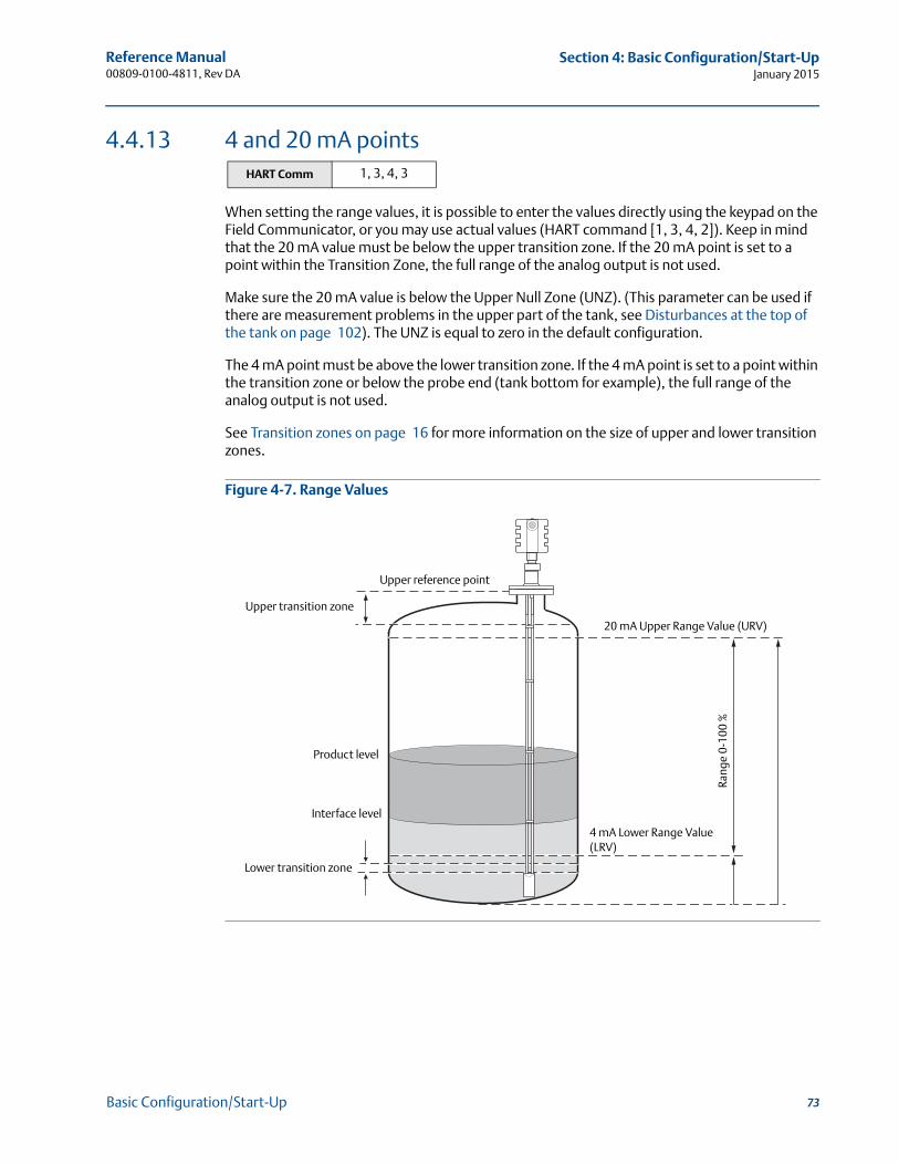
Reference Manual 00809-0100-4811, Rev DA
Section 4: Basic Configuration/Start-UpJanuary 2015
4.4.13 4 and 20 mA points
When setting the range values, it is possible to enter the values directly using the keypad on the Field Communicator, or you may use actual values (HART command [1, 3, 4, 2]). Keep in mind that the 20 mA value must be below the upper transition zone. If the 20 mA point is set to a point within the Transition Zone, the full range of the analog output is not used.
Make sure the 20 mA value is below the Upper Null Zone (UNZ). (This parameter can be used if there are measurement problems in the upper part of the tank, see Disturbances at the top of the tank on page 102). The UNZ is equal to zero in the default configuration.
The 4 mA point must be above the lower transition zone. If the 4 mA point is set to a point within the transition zone or below the probe end (tank bottom for example), the full range of the analog output is not used.
See Transition zones on page 16 for more information on the size of upper and lower transition zones.
Figure 4-7. Range Values
HART Comm 1, 3, 4, 3
20 mA Upper Range Value (URV)
Upper transition zone
Product level
Interface level
Lower transition zone
4 mA Lower Range Value (LRV)
Upper reference point
Rang
e 0-
100
%
73Basic Configuration/Start-Up
Reference Manual00809-0100-4811, Rev DA
Section 4: Basic Configuration/Start-UpJanuary 2015
4.5 Volume configuration
4.5.1 Transmitter variables
Select the Volume option to configure the transmitter for volume measurements.
4.5.2 Volume units
Select one of the following units:
Gallons
Liters
Imperial Gallons
Cubic Meters
Barrels
Cubic Yards
Cubic Feet
Cubic Inch
4.5.3 Tank type
Select a standard tank shape, or select the strapping option. Standard shapes are: Vertical Cylinder, Horizontal Cylinder, Vertical Bullet, Horizontal Bullet or Sphere. (If the PV is Level, select None for Tank Type).
If your tank does not correspond to any of the above tank shapes, select Strap Table.
4.5.4 Tank dimensions
If a standard tank type was chosen, enter the diameter and height of the tank. See Volume configuration on page 64 for information on how to specify tank dimensions.
4.5.5 Strapping table
If tank type Strapping Table was chosen, enter how many entries you will use, and the actual level and volume points. You can enter from 2 to 10 points. The strapping points must be entered such that the first point corresponds to the lowest level, and the last point corresponds to the topmost level of the tank.
HART Comm 1, 1, 1, 1
HART Comm 1, 3, 1, 2
HART Comm 1, 4, 3, 1
HART Comm 1, 4, 3, 2-3
HART Comm 1, 4, 3, 4
74 Basic Configuration/Start-Up
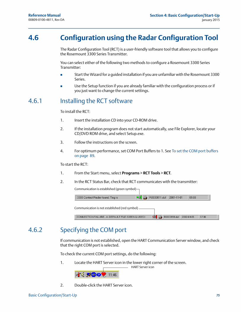
Reference Manual 00809-0100-4811, Rev DA
Section 4: Basic Configuration/Start-UpJanuary 2015
4.6 Configuration using the Radar Configuration Tool
The Radar Configuration Tool (RCT) is a user-friendly software tool that allows you to configure the Rosemount 3300 Series Transmitter.
You can select either of the following two methods to configure a Rosemount 3300 Series Transmitter:
Start the Wizard for a guided installation if you are unfamiliar with the Rosemount 3300 Series.
Use the Setup function if you are already familiar with the configuration process or if you just want to change the current settings.
4.6.1 Installing the RCT software
To install the RCT:
1. Insert the installation CD into your CD-ROM drive.
2. If the installation program does not start automatically, use File Explorer, locate your CD/DVD ROM drive, and select Setup.exe.
3. Follow the instructions on the screen.
4. For optimum performance, set COM Port Buffers to 1. See To set the COM port buffers on page 89.
To start the RCT:
1. From the Start menu, select Programs > RCT Tools > RCT.
2. In the RCT Status Bar, check that RCT communicates with the transmitter:
4.6.2 Specifying the COM port
If communication is not established, open the HART Communication Server window, and check that the right COM port is selected.
To check the current COM port settings, do the following:
1. Locate the HART Server icon in the lower right corner of the screen.
2. Double-click the HART Server icon.
Communication is established (green symbol)
Communication is not established (red symbol)
HART Server icon
75Basic Configuration/Start-Up
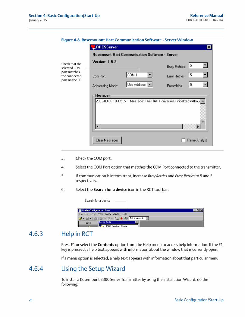
Reference Manual00809-0100-4811, Rev DA
Section 4: Basic Configuration/Start-UpJanuary 2015
Figure 4-8. Rosemouont Hart Communication Software - Server Window
3. Check the COM port.
4. Select the COM Port option that matches the COM Port connected to the transmitter.
5. If communication is intermittent, increase Busy Retries and Error Retries to 5 and 5 respectively.
6. Select the Search for a device icon in the RCT tool bar:
4.6.3 Help in RCT
Press F1 or select the Contents option from the Help menu to access help information. If the F1 key is pressed, a help text appears with information about the window that is currently open.
If a menu option is selected, a help text appears with information about that particular menu.
4.6.4 Using the Setup Wizard
To install a Rosemount 3300 Series Transmitter by using the installation Wizard, do the following:
Check that the selected COM port matches the connected port on the PC.
Search for a device
76 Basic Configuration/Start-Up
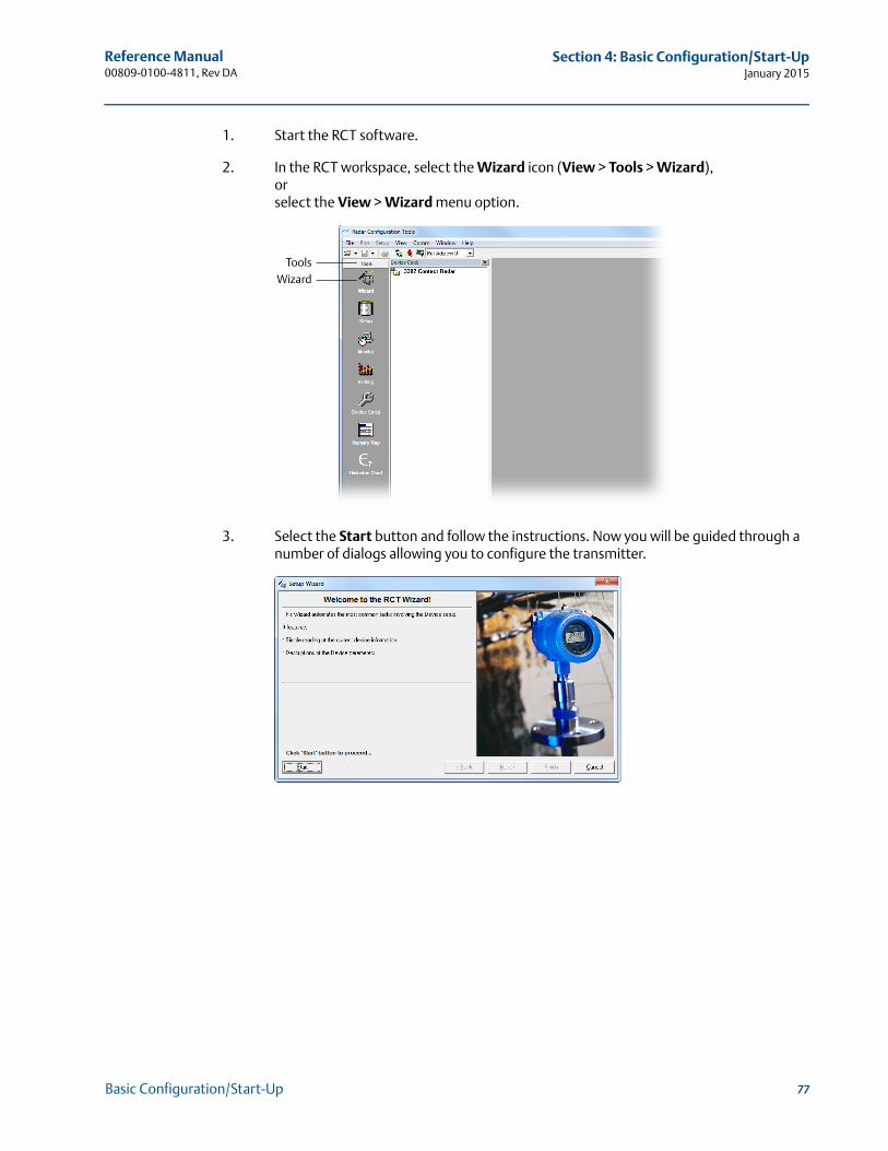
Reference Manual 00809-0100-4811, Rev DA
Section 4: Basic Configuration/Start-UpJanuary 2015
1. Start the RCT software.
2. In the RCT workspace, select the Wizard icon (View > Tools > Wizard),orselect the View > Wizard menu option.
3. Select the Start button and follow the instructions. Now you will be guided through a number of dialogs allowing you to configure the transmitter.
WizardTools
77Basic Configuration/Start-Up
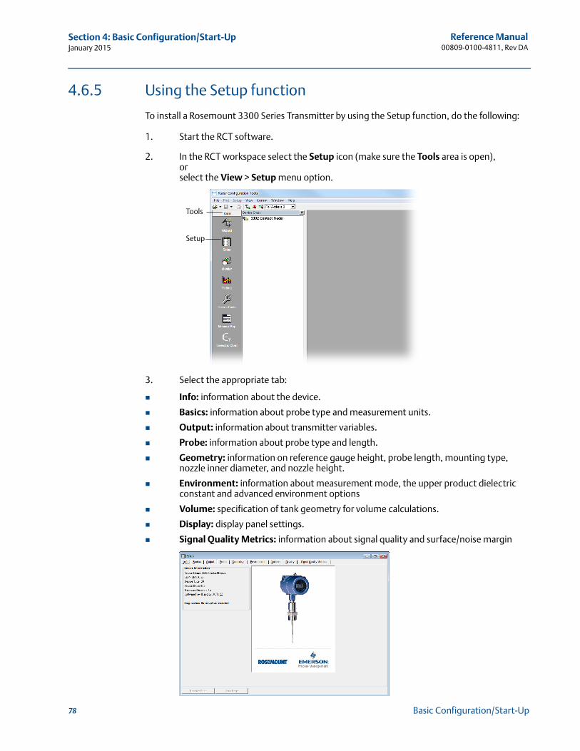
Reference Manual00809-0100-4811, Rev DA
Section 4: Basic Configuration/Start-UpJanuary 2015
4.6.5 Using the Setup function
To install a Rosemount 3300 Series Transmitter by using the Setup function, do the following:
1. Start the RCT software.
2. In the RCT workspace select the Setup icon (make sure the Tools area is open),orselect the View > Setup menu option.
3. Select the appropriate tab:
Info: information about the device.
Basics: information about probe type and measurement units.
Output: information about transmitter variables.
Probe: information about probe type and length.
Geometry: information on reference gauge height, probe length, mounting type, nozzle inner diameter, and nozzle height.
Environment: information about measurement mode, the upper product dielectric constant and advanced environment options
Volume: specification of tank geometry for volume calculations.
Display: display panel settings.
Signal Quality Metrics: information about signal quality and surface/noise margin
Setup
Tools
78 Basic Configuration/Start-Up
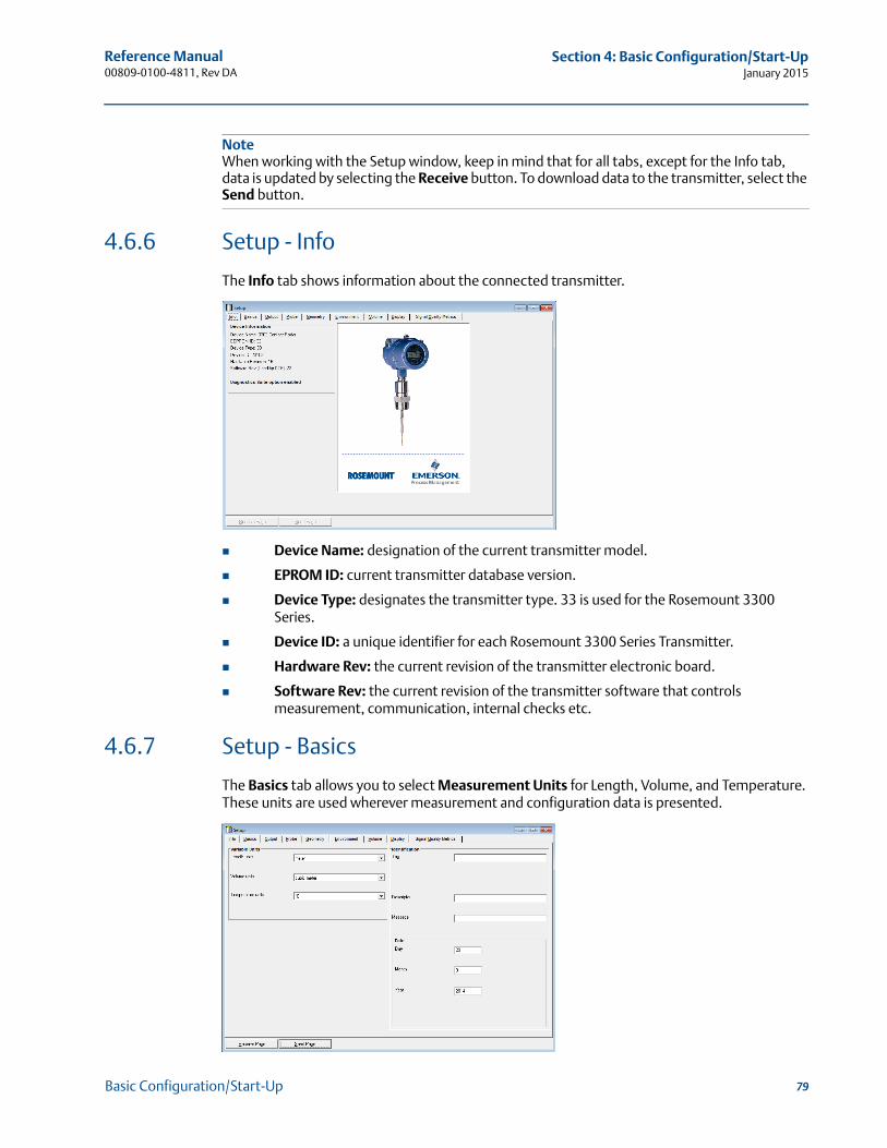
Reference Manual 00809-0100-4811, Rev DA
Section 4: Basic Configuration/Start-UpJanuary 2015
NoteWhen working with the Setup window, keep in mind that for all tabs, except for the Info tab, data is updated by selecting the Receive button. To download data to the transmitter, select the Send button.
4.6.6 Setup - Info
The Info tab shows information about the connected transmitter.
Device Name: designation of the current transmitter model.
EPROM ID: current transmitter database version.
Device Type: designates the transmitter type. 33 is used for the Rosemount 3300 Series.
Device ID: a unique identifier for each Rosemount 3300 Series Transmitter.
Hardware Rev: the current revision of the transmitter electronic board.
Software Rev: the current revision of the transmitter software that controls measurement, communication, internal checks etc.
4.6.7 Setup - Basics
The Basics tab allows you to select Measurement Units for Length, Volume, and Temperature. These units are used wherever measurement and configuration data is presented.
79Basic Configuration/Start-Up
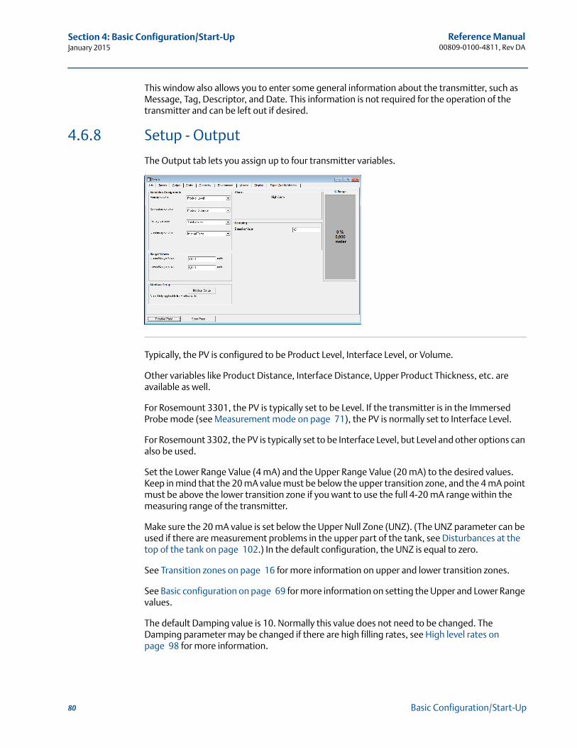
Reference Manual00809-0100-4811, Rev DA
Section 4: Basic Configuration/Start-UpJanuary 2015
This window also allows you to enter some general information about the transmitter, such as Message, Tag, Descriptor, and Date. This information is not required for the operation of the transmitter and can be left out if desired.
4.6.8 Setup - Output
The Output tab lets you assign up to four transmitter variables.
Typically, the PV is configured to be Product Level, Interface Level, or Volume.
Other variables like Product Distance, Interface Distance, Upper Product Thickness, etc. are available as well.
For Rosemount 3301, the PV is typically set to be Level. If the transmitter is in the Immersed Probe mode (see Measurement mode on page 71), the PV is normally set to Interface Level.
For Rosemount 3302, the PV is typically set to be Interface Level, but Level and other options can also be used.
Set the Lower Range Value (4 mA) and the Upper Range Value (20 mA) to the desired values. Keep in mind that the 20 mA value must be below the upper transition zone, and the 4 mA point must be above the lower transition zone if you want to use the full 4-20 mA range within the measuring range of the transmitter.
Make sure the 20 mA value is set below the Upper Null Zone (UNZ). (The UNZ parameter can be used if there are measurement problems in the upper part of the tank, see Disturbances at the top of the tank on page 102.) In the default configuration, the UNZ is equal to zero.
See Transition zones on page 16 for more information on upper and lower transition zones.
See Basic configuration on page 69 for more information on setting the Upper and Lower Range values.
The default Damping value is 10. Normally this value does not need to be changed. The Damping parameter may be changed if there are high filling rates, see High level rates on page 98 for more information.
80 Basic Configuration/Start-Up
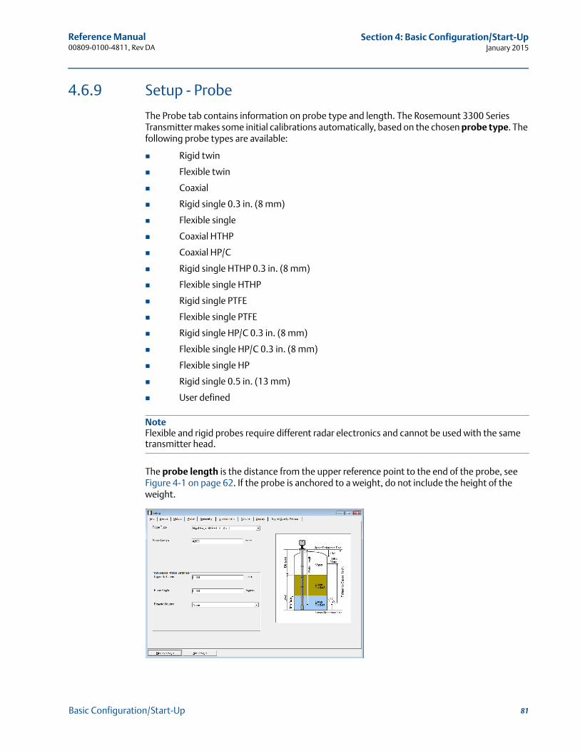
Reference Manual 00809-0100-4811, Rev DA
Section 4: Basic Configuration/Start-UpJanuary 2015
4.6.9 Setup - Probe
The Probe tab contains information on probe type and length. The Rosemount 3300 Series Transmitter makes some initial calibrations automatically, based on the chosen probe type. The following probe types are available:
Rigid twin
Flexible twin
Coaxial
Rigid single 0.3 in. (8 mm)
Flexible single
Coaxial HTHP
Coaxial HP/C
Rigid single HTHP 0.3 in. (8 mm)
Flexible single HTHP
Rigid single PTFE
Flexible single PTFE
Rigid single HP/C 0.3 in. (8 mm)
Flexible single HP/C 0.3 in. (8 mm)
Flexible single HP
Rigid single 0.5 in. (13 mm)
User defined
NoteFlexible and rigid probes require different radar electronics and cannot be used with the same transmitter head.
The probe length is the distance from the upper reference point to the end of the probe, see Figure 4-1 on page 62. If the probe is anchored to a weight, do not include the height of the weight.
81Basic Configuration/Start-Up
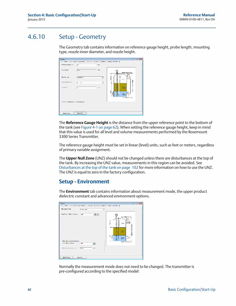
Reference Manual00809-0100-4811, Rev DA
Section 4: Basic Configuration/Start-UpJanuary 2015
4.6.10 Setup - Geometry
The Geometry tab contains information on reference gauge height, probe length, mounting type, nozzle inner diameter, and nozzle height.
The Reference Gauge Height is the distance from the upper reference point to the bottom of the tank (see Figure 4-1 on page 62). When setting the reference gauge height, keep in mind that this value is used for all level and volume measurements performed by the Rosemount 3300 Series Transmitter.
The reference gauge height must be set in linear (level) units, such as feet or meters, regardless of primary variable assignment.
The Upper Null Zone (UNZ) should not be changed unless there are disturbances at the top of the tank. By increasing the UNZ value, measurements in this region can be avoided. See Disturbances at the top of the tank on page 102 for more information on how to use the UNZ. The UNZ is equal to zero in the factory configuration.
Setup - Environment
The Environment tab contains information about measurement mode, the upper product dielectric constant and advanced environment options.
Normally the measurement mode does not need to be changed. The transmitter is pre-configured according to the specified model:
82 Basic Configuration/Start-Up

Reference Manual 00809-0100-4811, Rev DA
Section 4: Basic Configuration/Start-UpJanuary 2015
Table 4-3. Measurement Mode
Interface immersed probe is used for applications where the probe is fully immersed in liquid. In this mode the transmitter ignores the upper product level. See Interface measurements with fully immersed probes on page 99 for more information.
NoteUse interface immersed Probe only for applications where interface is measured for a fully immersed probe.
Dielectrics
In some applications there is heavy vapor above the product surface having a significant influence on the level measurement. In such cases, the vapor dielectric can be entered to compensate for this effect.
The default value is equal to 1, which corresponds to the dielectric constant of vacuum. Normally, this value does not need to be changed since the effect on measurement performance is very small for most vapors.
For interface measurements, the dielectric constant of the upper product is essential for calculating interface level and the upper product thickness. By default, the upper product dielectric parameter is about 2.
If the dielectric constant of the lower product is significantly smaller than the dielectric constant of water, you may need to make special adjustments. See section Service and Troubleshooting for further information.
The dielectric constant of the product is used for setting the appropriate signal amplitude thresholds, see section Service and Troubleshooting for more information on amplitude threshold settings. Normally, this parameter does not need to be changed for level measurements. However, for some products, measurement performance can be optimized by setting the proper product dielectric constant.
RCT contains tools to estimate the dielectric constant of the current product:
The dielectric chart lists the dielectric constant of a large number of products. Use one of the following methods to view the dielectric chart:- Select the View > Dielectric > Dielectric Chart menu option. - Select the Dielectric Chart icon in the project bar Advanced section.
The dielectric calculator allows you to calculate the dielectric constant of the upper product based on the following input:- actual upper product thickness,- the dielectric constant value stored in the transmitter, and- the upper product thickness presented by the transmitter.
Model Measurement mode
3301 Level(1), interface immersed probe
(1) Default setting.
3302 Level, level and interface(1), interface immersed probe
83Basic Configuration/Start-Up
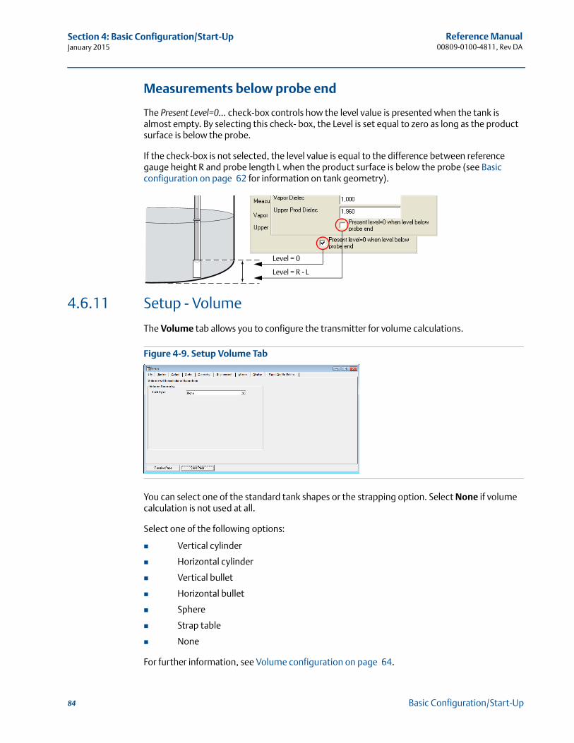
Reference Manual00809-0100-4811, Rev DA
Section 4: Basic Configuration/Start-UpJanuary 2015
Measurements below probe end
The Present Level=0... check-box controls how the level value is presented when the tank is almost empty. By selecting this check- box, the Level is set equal to zero as long as the product surface is below the probe.
If the check-box is not selected, the level value is equal to the difference between reference gauge height R and probe length L when the product surface is below the probe (see Basic configuration on page 62 for information on tank geometry).
4.6.11 Setup - Volume
The Volume tab allows you to configure the transmitter for volume calculations.
Figure 4-9. Setup Volume Tab
You can select one of the standard tank shapes or the strapping option. Select None if volume calculation is not used at all.
Select one of the following options:
Vertical cylinder
Horizontal cylinder
Vertical bullet
Horizontal bullet
Sphere
Strap table
None
For further information, see Volume configuration on page 64.
Level = 0
Level = R - L
84 Basic Configuration/Start-Up
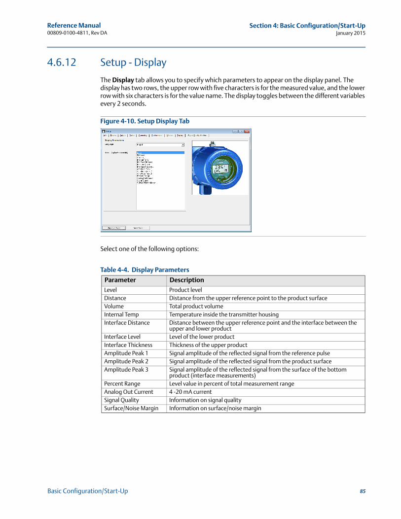
Reference Manual 00809-0100-4811, Rev DA
Section 4: Basic Configuration/Start-UpJanuary 2015
4.6.12 Setup - Display
The Display tab allows you to specify which parameters to appear on the display panel. The display has two rows, the upper row with five characters is for the measured value, and the lower row with six characters is for the value name. The display toggles between the different variables every 2 seconds.
Figure 4-10. Setup Display Tab
Select one of the following options:
Table 4-4. Display Parameters
Parameter Description
Level Product levelDistance Distance from the upper reference point to the product surfaceVolume Total product volumeInternal Temp Temperature inside the transmitter housingInterface Distance Distance between the upper reference point and the interface between the
upper and lower productInterface Level Level of the lower productInterface Thickness Thickness of the upper productAmplitude Peak 1 Signal amplitude of the reflected signal from the reference pulseAmplitude Peak 2 Signal amplitude of the reflected signal from the product surfaceAmplitude Peak 3 Signal amplitude of the reflected signal from the surface of the bottom
product (interface measurements)Percent Range Level value in percent of total measurement rangeAnalog Out Current 4 -20 mA currentSignal Quality Information on signal qualitySurface/Noise Margin Information on surface/noise margin
85Basic Configuration/Start-Up
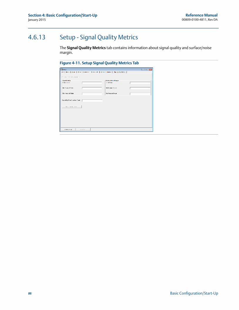
Reference Manual00809-0100-4811, Rev DA
Section 4: Basic Configuration/Start-UpJanuary 2015
4.6.13 Setup - Signal Quality Metrics
The Signal Quality Metrics tab contains information about signal quality and surface/noise margin.
Figure 4-11. Setup Signal Quality Metrics Tab
86 Basic Configuration/Start-Up
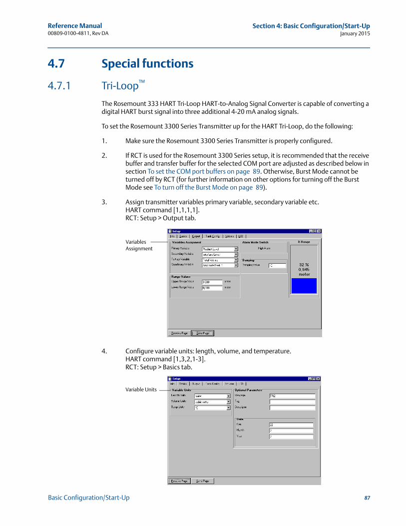
Reference Manual 00809-0100-4811, Rev DA
Section 4: Basic Configuration/Start-UpJanuary 2015
4.7 Special functions
4.7.1 Tri-Loop™
The Rosemount 333 HART Tri-Loop HART-to-Analog Signal Converter is capable of converting a digital HART burst signal into three additional 4-20 mA analog signals.
To set the Rosemount 3300 Series Transmitter up for the HART Tri-Loop, do the following:
1. Make sure the Rosemount 3300 Series Transmitter is properly configured.
2. If RCT is used for the Rosemount 3300 Series setup, it is recommended that the receive buffer and transfer buffer for the selected COM port are adjusted as described below in section To set the COM port buffers on page 89. Otherwise, Burst Mode cannot be turned off by RCT (for further information on other options for turning off the Burst Mode see To turn off the Burst Mode on page 89).
3. Assign transmitter variables primary variable, secondary variable etc.HART command [1,1,1,1].RCT: Setup > Output tab.
4. Configure variable units: length, volume, and temperature. HART command [1,3,2,1-3].RCT: Setup > Basics tab.
Variables Assignment
Variable Units
87Basic Configuration/Start-Up
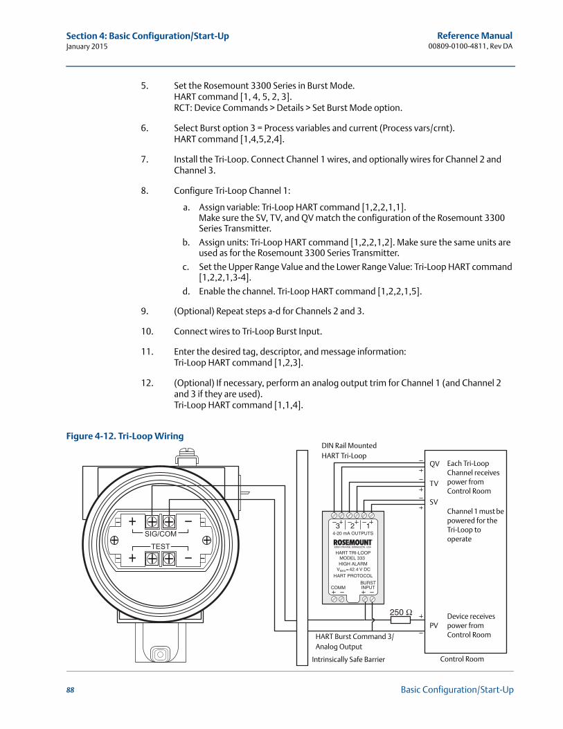
Reference Manual00809-0100-4811, Rev DA
Section 4: Basic Configuration/Start-UpJanuary 2015
5. Set the Rosemount 3300 Series in Burst Mode.HART command [1, 4, 5, 2, 3].RCT: Device Commands > Details > Set Burst Mode option.
6. Select Burst option 3 = Process variables and current (Process vars/crnt).HART command [1,4,5,2,4].
7. Install the Tri-Loop. Connect Channel 1 wires, and optionally wires for Channel 2 and Channel 3.
8. Configure Tri-Loop Channel 1:
a. Assign variable: Tri-Loop HART command [1,2,2,1,1].Make sure the SV, TV, and QV match the configuration of the Rosemount 3300 Series Transmitter.
b. Assign units: Tri-Loop HART command [1,2,2,1,2]. Make sure the same units are used as for the Rosemount 3300 Series Transmitter.
c. Set the Upper Range Value and the Lower Range Value: Tri-Loop HART command [1,2,2,1,3-4].
d. Enable the channel. Tri-Loop HART command [1,2,2,1,5].
9. (Optional) Repeat steps a-d for Channels 2 and 3.
10. Connect wires to Tri-Loop Burst Input.
11. Enter the desired tag, descriptor, and message information:Tri-Loop HART command [1,2,3].
12. (Optional) If necessary, perform an analog output trim for Channel 1 (and Channel 2 and 3 if they are used).Tri-Loop HART command [1,1,4].
Figure 4-12. Tri-Loop Wiring
Each Tri-Loop Channel receives power from Control Room
Channel 1 must be powered for the Tri-Loop to operate
Device receives power from Control RoomHART Burst Command 3/
Analog Output
Intrinsically Safe Barrier
DIN Rail MountedHART Tri-Loop
Control Room
QV
TV
SV
PV
88 Basic Configuration/Start-Up

Reference Manual 00809-0100-4811, Rev DA
Section 4: Basic Configuration/Start-UpJanuary 2015
See the Model 333 HART® Tri-Loop HART-to-Analog Signal Converter Reference Manual (Document No. 00809-0100-4754) for further information on how to install and configure the Tri-Loop.
To turn off the Burst Mode
To turn off the Burst Mode, use one of the following options:
The RCT program (requires that the receive and transfer buffers for the selected COM port are adjusted)
The Rosemount Burst Mode Switch software
A Field Communicator
The AMS® Device Manager software
To set the COM port buffers
To be able to communicate with the Rosemount 3300 Series in Burst Mode, the receive and transfer buffers need to be adjusted as written below.
If you have Windows XP
1. In the MS Windows™ Control Panel open the System option.
2. Choose the Hardware tab and select the Device Manager button.
3. Expand the Ports node in the tree view.
4. Click the right mouse button on the selected COM port and choose Properties.
5. Select the Port Settings tab and click the Advanced button.
6. Drag the Receive Buffer and Transfer Buffer slides to 1.
7. Select the OK button.
8. Reboot the computer.
If you have Windows 7, Windows 8, or Windows 8.1
1. In the Start menu, select Control Panel > System and Security > System > Device Manager.
2. Double-click Ports (COM & LPT).
3. Right-click on the selected COM port and select Properties.
4. Select the Port Settings tab and then select the Advanced button.
5. Drag the Receive Buffer and Transmit Buffer to 1.
6. Click OK.
7. Restart the computer.
89Basic Configuration/Start-Up

90
Reference Manual00809-0100-4811, Rev DA
Section 4: Basic Configuration/Start-UpJanuary 2015
Basic Configuration/Start-Up
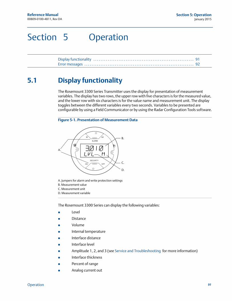
Reference Manual 00809-0100-4811, Rev DA
Section 5: OperationJanuary 2015
Section 5 Operation
Display functionality . . . . . . . . . . . . . . . . . . . . . . . . . . . . . . . . . . . . . . . . . . . . . . . . . . . . . . . . 91Error messages . . . . . . . . . . . . . . . . . . . . . . . . . . . . . . . . . . . . . . . . . . . . . . . . . . . . . . . . . . . . . 92
5.1 Display functionality
The Rosemount 3300 Series Transmitter uses the display for presentation of measurement variables. The display has two rows, the upper row with five characters is for the measured value, and the lower row with six characters is for the value name and measurement unit. The display toggles between the different variables every two seconds. Variables to be presented are configurable by using a Field Communicator or by using the Radar Configuration Tools software.
Figure 5-1. Presentation of Measurement Data
The Rosemount 3300 Series can display the following variables:
Level
Distance
Volume
Internal temperature
Interface distance
Interface level
Amplitude 1, 2, and 3 (see Service and Troubleshooting for more information)
Interface thickness
Percent of range
Analog current out
B.
C.
D.
A.
A. Jumpers for alarm and write protection settingsB. Measurement valueC. Measurement unitD. Measurement variable
91Operation
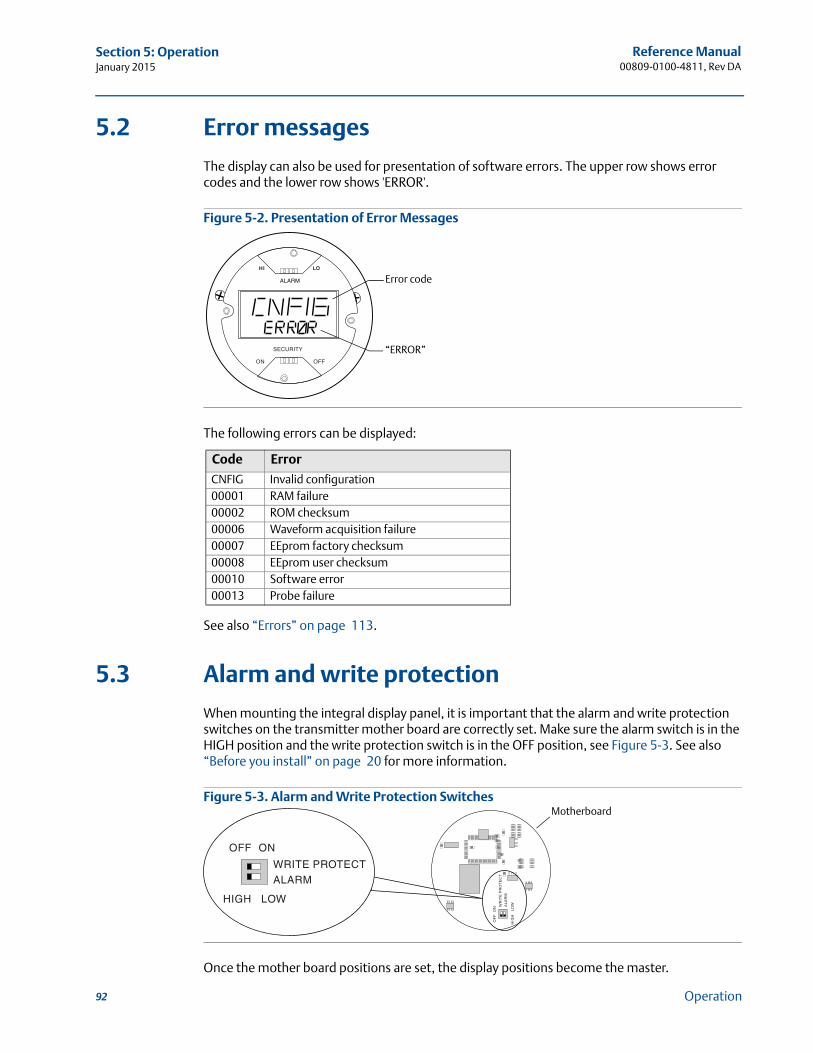
Reference Manual00809-0100-4811, Rev DA
Section 5: OperationJanuary 2015
5.2 Error messages
The display can also be used for presentation of software errors. The upper row shows error codes and the lower row shows 'ERROR'.
Figure 5-2. Presentation of Error Messages
The following errors can be displayed:
See also “Errors” on page 113.
5.3 Alarm and write protection
When mounting the integral display panel, it is important that the alarm and write protection switches on the transmitter mother board are correctly set. Make sure the alarm switch is in the HIGH position and the write protection switch is in the OFF position, see Figure 5-3. See also “Before you install” on page 20 for more information.
Figure 5-3. Alarm and Write Protection Switches
Once the mother board positions are set, the display positions become the master.
Code Error
CNFIG Invalid configuration00001 RAM failure00002 ROM checksum00006 Waveform acquisition failure00007 EEprom factory checksum00008 EEprom user checksum00010 Software error00013 Probe failure
Error code
“ERROR”
Motherboard
92 Operation

Reference Manual 00809-0100-4811, Rev DA
Section 6: Service and TroubleshootingJanuary 2015
Section 6 Service and Troubleshooting
Safety messages . . . . . . . . . . . . . . . . . . . . . . . . . . . . . . . . . . . . . . . . . . . . . . . . . . . . . . . . . . . . 93Advanced configuration . . . . . . . . . . . . . . . . . . . . . . . . . . . . . . . . . . . . . . . . . . . . . . . . . . . . . 94Service . . . . . . . . . . . . . . . . . . . . . . . . . . . . . . . . . . . . . . . . . . . . . . . . . . . . . . . . . . . . . . . . . . . . 100Diagnostic messages . . . . . . . . . . . . . . . . . . . . . . . . . . . . . . . . . . . . . . . . . . . . . . . . . . . . . . . . 112
6.1 Safety messages
Procedures and instructions in this section may require special precautions to ensure the safety of the personnel performing the operations. Information that raises potential safety issues is
indicated by a warning symbol ( ). Please refer to the following safety messages before performing an operation preceded by this symbol.
Explosions could result in death or serious injury.
Verify that the operating environment of the gauge is consistent with the appropriate hazardous locations certifications.
Before connecting a HART®-based communicator in an explosive atmosphere, make sure the instruments in the loop are installed in accordance with intrinsically safe or non-incendive field wiring practices.
In an Explosion-proof/Flameproof installation, do not remove the transmitter cover when power is applied to the unit.
Eliminate the risk of ESD discharge prior to dismounting the transmitter head. Probes may generate an ignition-capable level of electrostatic charge under extreme
conditions. During any type of installation or maintenance in a potentially explosive atmosphere, the responsible person should make sure that any ESD risks are eliminated before attempting to separate the probe from the transmitter head.
Failure to follow safe installation and servicing guidelines could result in death or serious injury.
Make sure only qualified personnel perform the installation. Use the equipment only as specified in this manual. Failure to do so may impair the
protection provided by the equipment. Do not perform any service other than those contained in this manual unless you are
qualified.High voltage that may be present on leads could cause electrical shock.
Avoid contact with leads and terminals. Make sure the main power to the Rosemount 3300 Series Transmitter is off, and the
lines to any other external power source are disconnected or not powered while wiring the gauge.
Probes covered with plastic and/or with plastic discs may generate an ignition-capable level of electrostatic charge under certain extreme conditions. Therefore, when the probe is used in a potentially explosive atmosphere, appropriate measures must be taken to prevent electrostatic discharge.
Process leaks could result in death or serious injury.
Make sure that the transmitter is handled carefully. If the Process Seal is damaged, gas might escape from the tank if the transmitter head is removed from the probe.
93Service and Troubleshooting
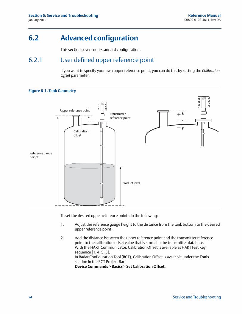
Reference Manual00809-0100-4811, Rev DA
Section 6: Service and TroubleshootingJanuary 2015
6.2 Advanced configuration
This section covers non-standard configuration.
6.2.1 User defined upper reference point
If you want to specify your own upper reference point, you can do this by setting the Calibration Offset parameter.
Figure 6-1. Tank Geometry
To set the desired upper reference point, do the following:
1. Adjust the reference gauge height to the distance from the tank bottom to the desired upper reference point.
2. Add the distance between the upper reference point and the transmitter reference point to the calibration offset value that is stored in the transmitter database. With the HART Communicator, Calibration Offset is available as HART Fast Key sequence [1, 4, 5, 5].In Radar Configuration Tool (RCT), Calibration Offset is available under the Tools section in the RCT Project Bar:Device Commands > Basics > Set Calibration Offset.
Reference gauge height
Product level
Upper reference pointTransmitter reference point
Calibration offset
94 Service and Troubleshooting
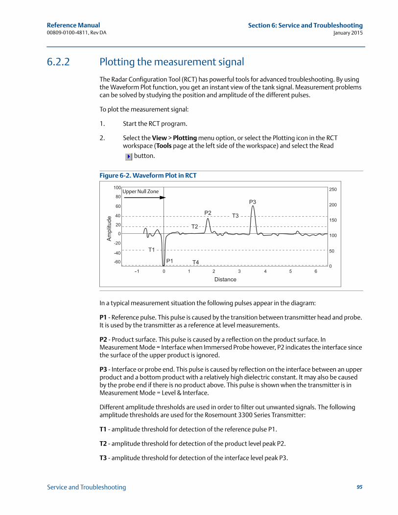
Reference Manual 00809-0100-4811, Rev DA
Section 6: Service and TroubleshootingJanuary 2015
6.2.2 Plotting the measurement signal
The Radar Configuration Tool (RCT) has powerful tools for advanced troubleshooting. By using the Waveform Plot function, you get an instant view of the tank signal. Measurement problems can be solved by studying the position and amplitude of the different pulses.
To plot the measurement signal:
1. Start the RCT program.
2. Select the View > Plotting menu option, or select the Plotting icon in the RCT workspace (Tools page at the left side of the workspace) and select the Read
button.
Figure 6-2. Waveform Plot in RCT
In a typical measurement situation the following pulses appear in the diagram:
P1 - Reference pulse. This pulse is caused by the transition between transmitter head and probe. It is used by the transmitter as a reference at level measurements.
P2 - Product surface. This pulse is caused by a reflection on the product surface. In Measurement Mode = Interface when Immersed Probe however, P2 indicates the interface since the surface of the upper product is ignored.
P3 - Interface or probe end. This pulse is caused by reflection on the interface between an upper product and a bottom product with a relatively high dielectric constant. It may also be caused by the probe end if there is no product above. This pulse is shown when the transmitter is in Measurement Mode = Level & Interface.
Different amplitude thresholds are used in order to filter out unwanted signals. The following amplitude thresholds are used for the Rosemount 3300 Series Transmitter:
T1 - amplitude threshold for detection of the reference pulse P1.
T2 - amplitude threshold for detection of the product level peak P2.
T3 - amplitude threshold for detection of the interface level peak P3.
-
Upper Null Zone
95Service and Troubleshooting
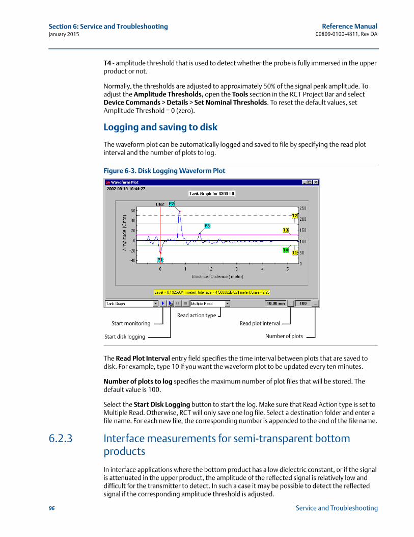
Reference Manual00809-0100-4811, Rev DA
Section 6: Service and TroubleshootingJanuary 2015
T4 - amplitude threshold that is used to detect whether the probe is fully immersed in the upper product or not.
Normally, the thresholds are adjusted to approximately 50% of the signal peak amplitude. To adjust the Amplitude Thresholds, open the Tools section in the RCT Project Bar and select Device Commands > Details > Set Nominal Thresholds. To reset the default values, set Amplitude Threshold = 0 (zero).
Logging and saving to disk
The waveform plot can be automatically logged and saved to file by specifying the read plot interval and the number of plots to log.
Figure 6-3. Disk Logging Waveform Plot
The Read Plot Interval entry field specifies the time interval between plots that are saved to disk. For example, type 10 if you want the waveform plot to be updated every ten minutes.
Number of plots to log specifies the maximum number of plot files that will be stored. The default value is 100.
Select the Start Disk Logging button to start the log. Make sure that Read Action type is set to Multiple Read. Otherwise, RCT will only save one log file. Select a destination folder and enter a file name. For each new file, the corresponding number is appended to the end of the file name.
6.2.3 Interface measurements for semi-transparent bottom products
In interface applications where the bottom product has a low dielectric constant, or if the signal is attenuated in the upper product, the amplitude of the reflected signal is relatively low and difficult for the transmitter to detect. In such a case it may be possible to detect the reflected signal if the corresponding amplitude threshold is adjusted.
Start disk logging
Start monitoring
Number of plots
Read plot interval
Read action type
96 Service and Troubleshooting
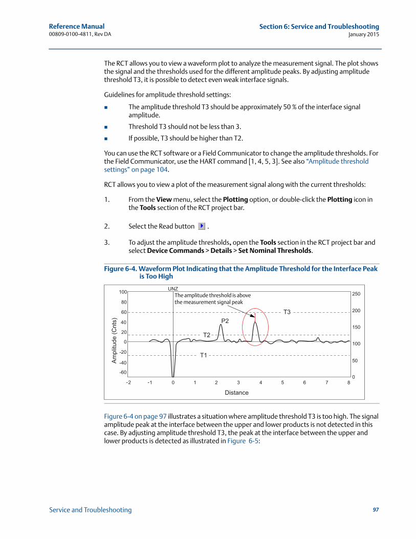
Reference Manual 00809-0100-4811, Rev DA
Section 6: Service and TroubleshootingJanuary 2015
The RCT allows you to view a waveform plot to analyze the measurement signal. The plot shows the signal and the thresholds used for the different amplitude peaks. By adjusting amplitude threshold T3, it is possible to detect even weak interface signals.
Guidelines for amplitude threshold settings:
The amplitude threshold T3 should be approximately 50 % of the interface signal amplitude.
Threshold T3 should not be less than 3.
If possible, T3 should be higher than T2.
You can use the RCT software or a Field Communicator to change the amplitude thresholds. For the Field Communicator, use the HART command [1, 4, 5, 3]. See also “Amplitude threshold settings” on page 104.
RCT allows you to view a plot of the measurement signal along with the current thresholds:
1. From the View menu, select the Plotting option, or double-click the Plotting icon in the Tools section of the RCT project bar.
2. Select the Read button .
3. To adjust the amplitude thresholds, open the Tools section in the RCT project bar and select Device Commands > Details > Set Nominal Thresholds.
Figure 6-4. Waveform Plot Indicating that the Amplitude Threshold for the Interface Peak is Too High
Figure 6-4 on page 97 illustrates a situation where amplitude threshold T3 is too high. The signal amplitude peak at the interface between the upper and lower products is not detected in this case. By adjusting amplitude threshold T3, the peak at the interface between the upper and lower products is detected as illustrated in Figure 6-5:
The amplitude threshold is above the measurement signal peak
97Service and Troubleshooting
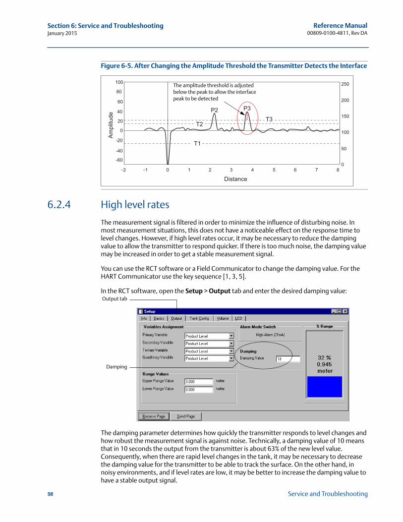
Reference Manual00809-0100-4811, Rev DA
Section 6: Service and TroubleshootingJanuary 2015
Figure 6-5. After Changing the Amplitude Threshold the Transmitter Detects the Interface
6.2.4 High level rates
The measurement signal is filtered in order to minimize the influence of disturbing noise. In most measurement situations, this does not have a noticeable effect on the response time to level changes. However, if high level rates occur, it may be necessary to reduce the damping value to allow the transmitter to respond quicker. If there is too much noise, the damping value may be increased in order to get a stable measurement signal.
You can use the RCT software or a Field Communicator to change the damping value. For the HART Communicator use the key sequence [1, 3, 5].
In the RCT software, open the Setup > Output tab and enter the desired damping value:
The damping parameter determines how quickly the transmitter responds to level changes and how robust the measurement signal is against noise. Technically, a damping value of 10 means that in 10 seconds the output from the transmitter is about 63% of the new level value. Consequently, when there are rapid level changes in the tank, it may be necessary to decrease the damping value for the transmitter to be able to track the surface. On the other hand, in noisy environments, and if level rates are low, it may be better to increase the damping value to have a stable output signal.
The amplitude threshold is adjusted below the peak to allow the interface peak to be detected
Damping
Output tab
98 Service and Troubleshooting

Reference Manual 00809-0100-4811, Rev DA
Section 6: Service and TroubleshootingJanuary 2015
6.2.5 Interface measurements with fully immersed probes
The Rosemount 3300 Series has a measurement option which makes it possible to handle interface measurements when the product level is not visible, for example in a full bridle pipe as illustrated in Figure 6-6. In this case, the probe is fully immersed into the upper product, and only the interface level is detected by the transmitter. Even if the upper product level drops, it is ignored by the transmitter which continues to measure only the interface level, but the measurement accuracy is reduced since the transmitter does not take into account the influence of the air gap above the product surface.
The Measurement Mode parameter is available via the HART command [1, 3, 3, 4]. Select the Interface when Immersed Probe option.
Measurement mode Interface when Immersed Probe can also be activated in the RCT software:
1. Open the Setup window.
2. Select the Environment tab.
3. Select Measurement Mode Interface when Immersed Probe.
4. Select the Send Page button.
NoteDo not use Measurement Mode Interface when Immersed Probe in “standard” applications when both interface level and product level are measured.
If the product level drops, the air filled region in the upper part of the pipe will slightly reduce the measurement accuracy of the interface level. To achieve high accuracy in this measurement mode the probe must be fully immersed.
Figure 6-6. Interface Level Measurements in a Full Bridle Pipe
NoteAdjust Threshold T2 if the level pulse is not detected.
Interface distance
Interface level
Product level is ignored
Interface level is measured
99Service and Troubleshooting
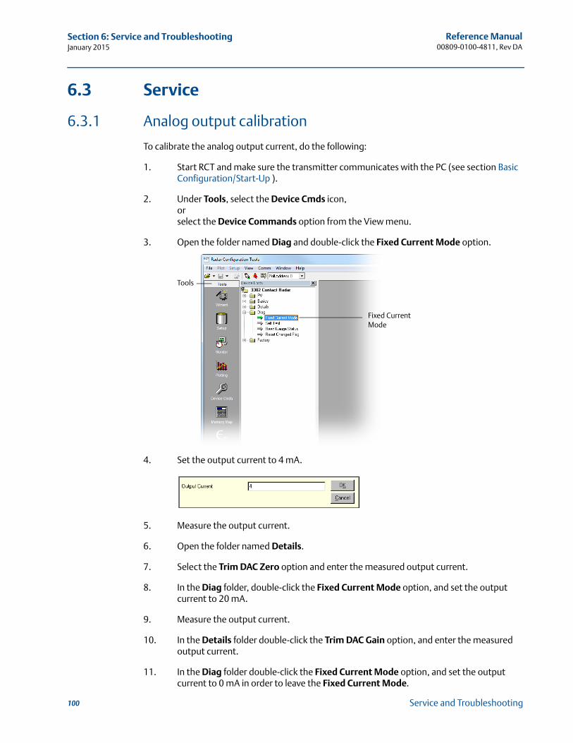
Reference Manual00809-0100-4811, Rev DA
Section 6: Service and TroubleshootingJanuary 2015
6.3 Service
6.3.1 Analog output calibration
To calibrate the analog output current, do the following:
1. Start RCT and make sure the transmitter communicates with the PC (see section Basic Configuration/Start-Up ).
2. Under Tools, select the Device Cmds icon,orselect the Device Commands option from the View menu.
3. Open the folder named Diag and double-click the Fixed Current Mode option.
4. Set the output current to 4 mA.
5. Measure the output current.
6. Open the folder named Details.
7. Select the Trim DAC Zero option and enter the measured output current.
8. In the Diag folder, double-click the Fixed Current Mode option, and set the output current to 20 mA.
9. Measure the output current.
10. In the Details folder double-click the Trim DAC Gain option, and enter the measured output current.
11. In the Diag folder double-click the Fixed Current Mode option, and set the output current to 0 mA in order to leave the Fixed Current Mode.
Fixed Current Mode
Tools
100 Service and Troubleshooting

Reference Manual 00809-0100-4811, Rev DA
Section 6: Service and TroubleshootingJanuary 2015
6.3.2 Level and distance calibration
When calibrating the transmitter, it is important that the product surface is calm and the tank is not being filled or emptied.
A complete calibration is performed in two steps:
1. Calibrate distance measurement by adjusting the calibration offset parameter.
2. Calibrate level measurement by adjusting the reference gauge height.
Distance calibration
1. Measure the actual distance between the upper reference point and the product surface.
2. Adjust the calibration offset so that the distance measured by the transmitter corresponds to the actual distance. The calibration offset parameter is available via HART command [1, 4, 5, 5],orRCT: open the Tools section in the project bar and select Device Commands > Basics > Set Calibration Offset.
Level calibration
1. Measure the actual product level.
2. Adjust the reference gauge height so that the measured product level corresponds to the actual level.
Figure 6-7. Distance and Level Calibration
Level
Reference point
Reference gauge height
Distance
Reference point
101Service and Troubleshooting
Reference Manual00809-0100-4811, Rev DA
Section 6: Service and TroubleshootingJanuary 2015
6.3.3 Disturbances at the top of the tank
Using the Trim Near Zone function
For transmitters using the Guided Wave Radar technology, the performance in the Near Zone (referred to as the region between 0-1.6 ft (0-0.5 m) below the upper reference point) is normally somewhat limited. However, the Rosemount 3300 Series Transmitter is equipped with a software functionality that minimizes the upper transition zone. The factory setting is normally sufficient and does not need to be repeated after installation.
However, since the setting is optimized depending on actual installation, further trimming may be necessary in the case of unfavorable conditions. For example, this may be the case if a single lead probe is mounted in a small nozzle, or if there are disturbing obstacles in the near zone. The trimming means that the measurement performance in the near zone is maintained even under these conditions and prevents false echo indication.
To trim the near zone perfomance, do the following:
1. Make sure the product level is below the near zone region (0-1.6 ft (0-0.5 m) below the upper reference point).
2. Start RCT.
3. Select the Device Commands option from the View menu.
4. Open the Details folder.
5. Select the Trim Near Zone option.
6. Select the Update option and click OK.
NoteThe Trim Near Zone function should only be used for reducing impact from constant disturbances. It is not suitable for occasional disturbances.
To reset the transmitter to factory settings do the following:
1. Start RCT.
2. Select the Device Commands option from the View menu.
3. Open the Details folder.
4. Select the Trim Near Zone option.
5. Select the Reset to Factory Settings option and click OK.
Changing the Upper Null Zone
Measurements are not performed within the Upper Null Zone (UNZ). By setting the UNZ parameter to zero, measurements can be performed in the region close to the flange (near zone). However, it is very important that there are no disturbances in that region if UNZ is set to zero.
102 Service and Troubleshooting
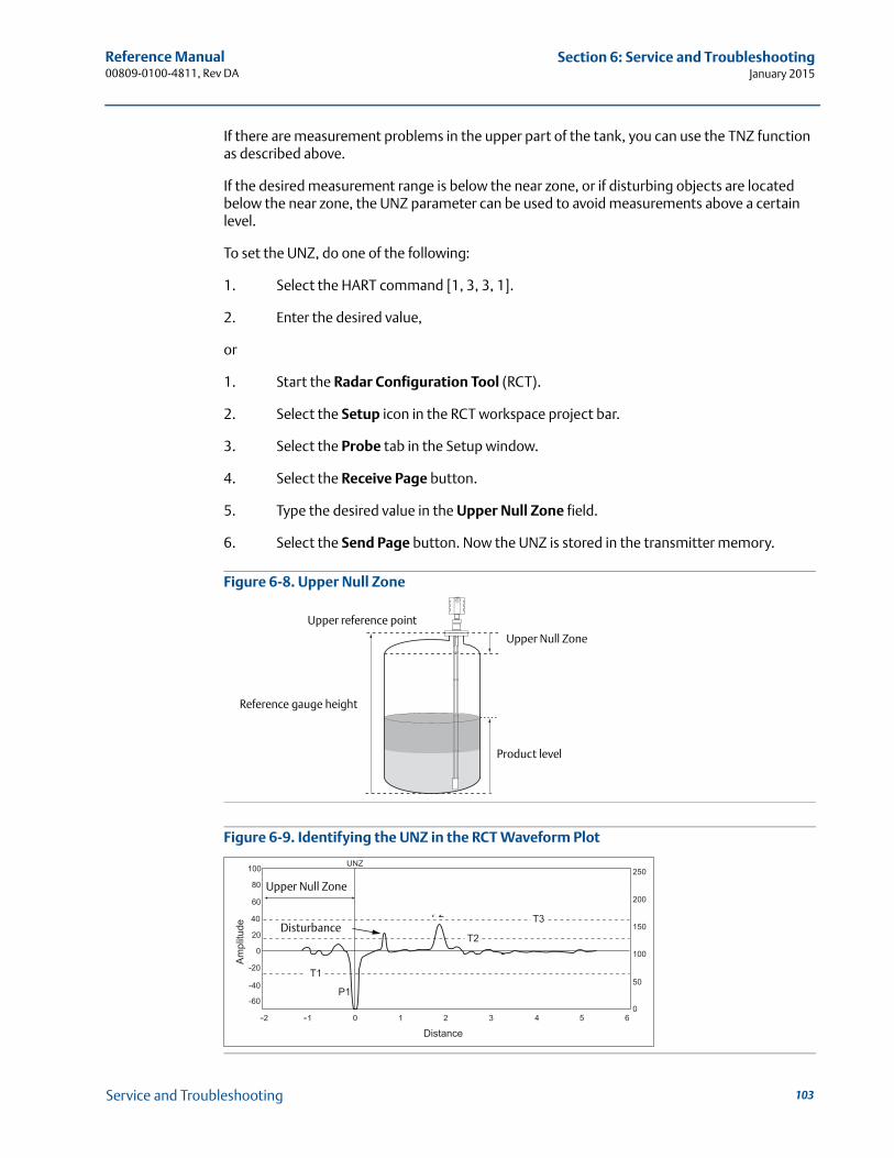
Reference Manual 00809-0100-4811, Rev DA
Section 6: Service and TroubleshootingJanuary 2015
If there are measurement problems in the upper part of the tank, you can use the TNZ function as described above.
If the desired measurement range is below the near zone, or if disturbing objects are located below the near zone, the UNZ parameter can be used to avoid measurements above a certain level.
To set the UNZ, do one of the following:
1. Select the HART command [1, 3, 3, 1].
2. Enter the desired value,
or
1. Start the Radar Configuration Tool (RCT).
2. Select the Setup icon in the RCT workspace project bar.
3. Select the Probe tab in the Setup window.
4. Select the Receive Page button.
5. Type the desired value in the Upper Null Zone field.
6. Select the Send Page button. Now the UNZ is stored in the transmitter memory.
Figure 6-8. Upper Null Zone
Figure 6-9. Identifying the UNZ in the RCT Waveform Plot
Reference gauge height
Upper Null Zone
Product level
Upper reference point
--
Upper Null Zone
Disturbance
103Service and Troubleshooting
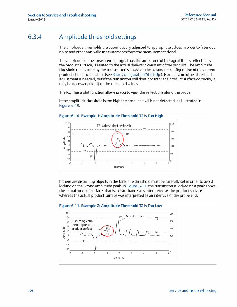
Reference Manual00809-0100-4811, Rev DA
Section 6: Service and TroubleshootingJanuary 2015
6.3.4 Amplitude threshold settings
The amplitude thresholds are automatically adjusted to appropriate values in order to filter out noise and other non-valid measurements from the measurement signal.
The amplitude of the measurement signal, i.e. the amplitude of the signal that is reflected by the product surface, is related to the actual dielectric constant of the product. The amplitude threshold that is used by the transmitter is based on the parameter configuration of the current product dielectric constant (see Basic Configuration/Start-Up ). Normally, no other threshold adjustment is needed, but if the transmitter still does not track the product surface correctly, it may be necessary to adjust the threshold values.
The RCT has a plot function allowing you to view the reflections along the probe.
If the amplitude threshold is too high the product level is not detected, as illustrated in Figure 6-10.
Figure 6-10. Example 1: Amplitude Threshold T2 is Too High
If there are disturbing objects in the tank, the threshold must be carefully set in order to avoid locking on the wrong amplitude peak. In Figure 6-11, the transmitter is locked on a peak above the actual product surface, that is a disturbance was interpreted as the product surface, whereas the actual product surface was interpreted as an interface or the probe end.
Figure 6-11. Example 2: Amplitude Threshold T2 is Too Low
P1
T1
T2
T3
Am
plitu
de
100
80
60
-60
40
-40
20
-20
0 100
50
0
150
200
250
--
T2 is above the Level peak
P1
P2
P3
T1
T2
T3
Am
plitu
de
100
80
60
-60
40
-40
20
-20
0 100
50
0
150
200
250
Actual surfaceDisturbing echo misinterpreted as product surface
104 Service and Troubleshooting
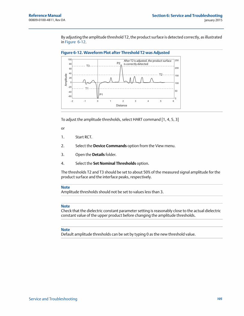
Reference Manual 00809-0100-4811, Rev DA
Section 6: Service and TroubleshootingJanuary 2015
By adjusting the amplitude threshold T2, the product surface is detected correctly, as illustrated in Figure 6-12.
Figure 6-12. Waveform Plot after Threshold T2 was Adjusted
To adjust the amplitude thresholds, select HART command [1, 4, 5, 3]
or
1. Start RCT.
2. Select the Device Commands option from the View menu.
3. Open the Details folder.
4. Select the Set Nominal Thresholds option.
The thresholds T2 and T3 should be set to about 50% of the measured signal amplitude for the product surface and the interface peaks, respectively.
NoteAmplitude thresholds should not be set to values less than 3.
NoteCheck that the dielectric constant parameter setting is reasonably close to the actual dielectric constant value of the upper product before changing the amplitude thresholds.
NoteDefault amplitude thresholds can be set by typing 0 as the new threshold value.
P1
P2
T1
T2
T3A
mpl
itude
100
80
60
-60
40
-40
20
-20
0 100
50
0
150
200
250
After T2 is adjusted, the product surface is correctly detected
105Service and Troubleshooting
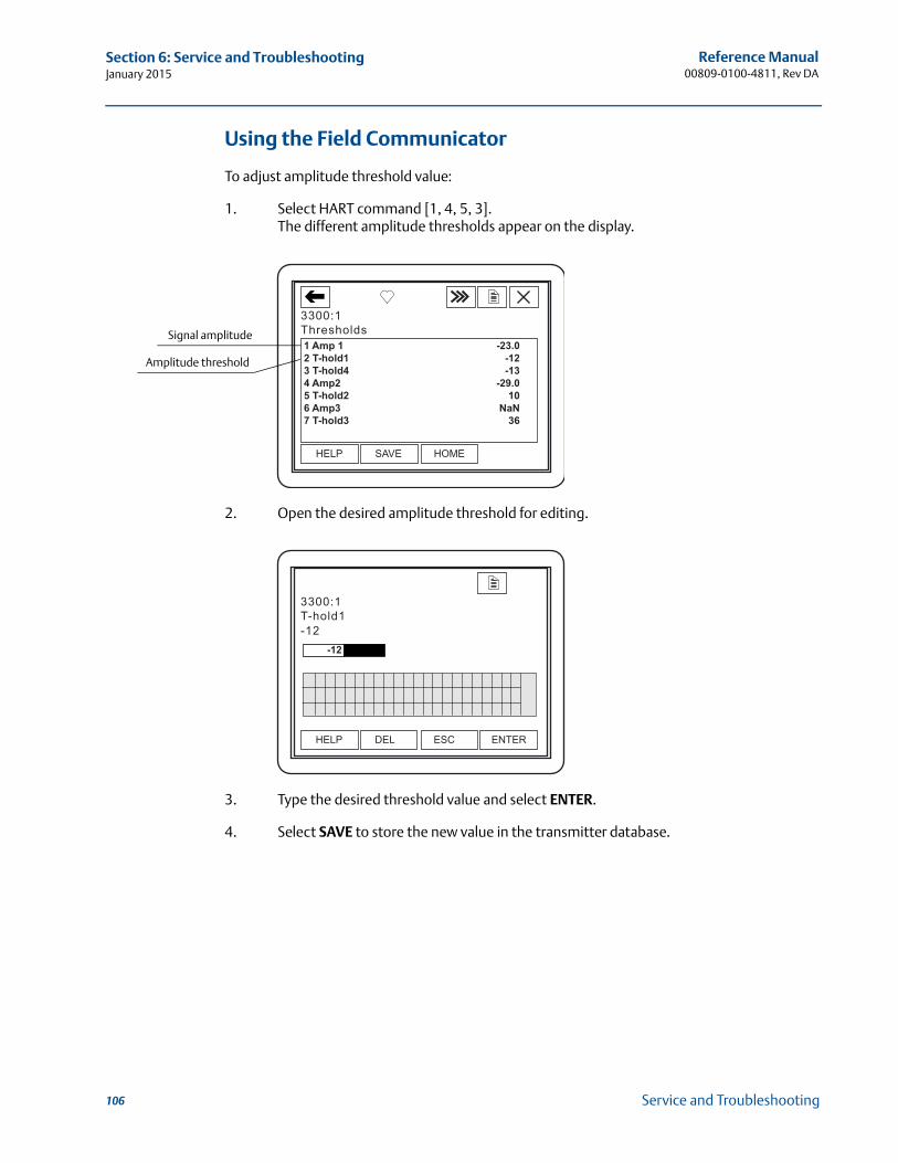
Reference Manual00809-0100-4811, Rev DA
Section 6: Service and TroubleshootingJanuary 2015
Using the Field Communicator
To adjust amplitude threshold value:
1. Select HART command [1, 4, 5, 3].The different amplitude thresholds appear on the display.
2. Open the desired amplitude threshold for editing.
3. Type the desired threshold value and select ENTER.
4. Select SAVE to store the new value in the transmitter database.
Signal amplitude
Amplitude threshold
106 Service and Troubleshooting
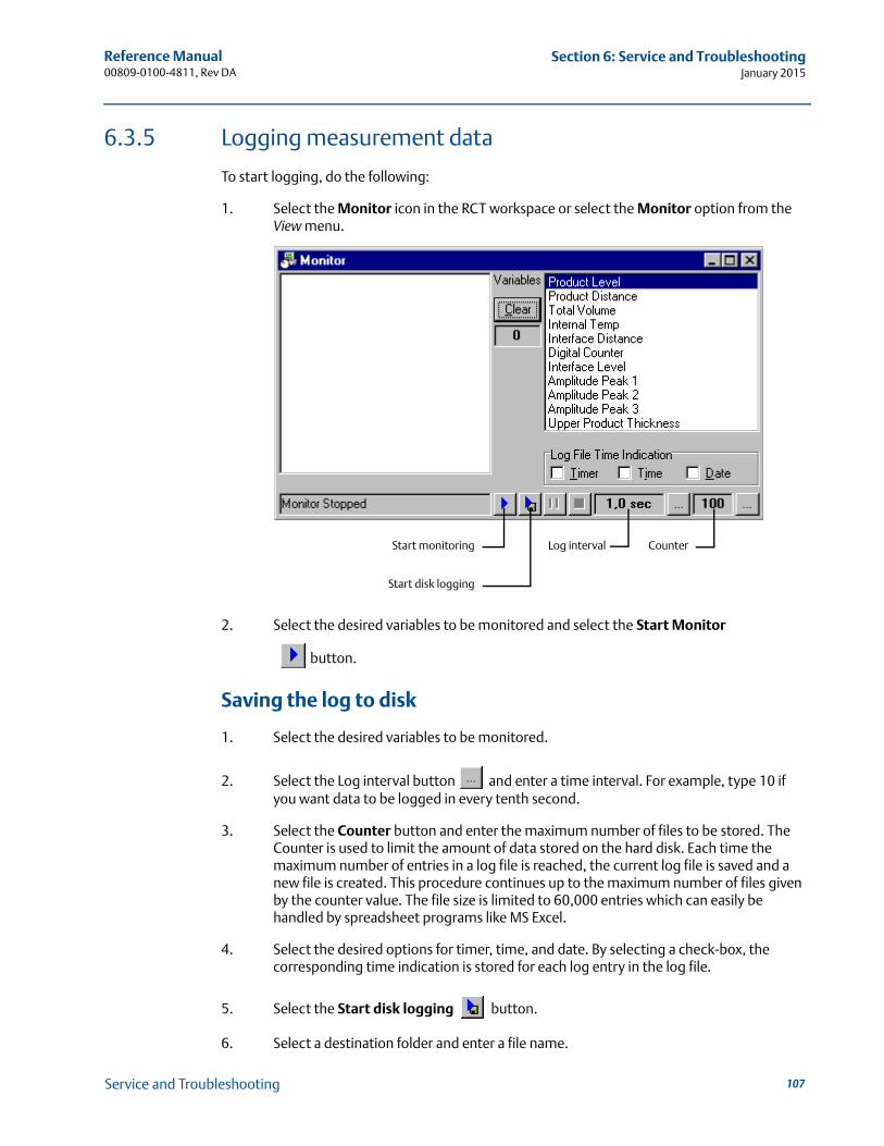
Reference Manual 00809-0100-4811, Rev DA
Section 6: Service and TroubleshootingJanuary 2015
6.3.5 Logging measurement data
To start logging, do the following:
1. Select the Monitor icon in the RCT workspace or select the Monitor option from the View menu.
2. Select the desired variables to be monitored and select the Start Monitor
button.
Saving the log to disk
1. Select the desired variables to be monitored.
2. Select the Log interval button and enter a time interval. For example, type 10 if you want data to be logged in every tenth second.
3. Select the Counter button and enter the maximum number of files to be stored. The Counter is used to limit the amount of data stored on the hard disk. Each time the maximum number of entries in a log file is reached, the current log file is saved and a new file is created. This procedure continues up to the maximum number of files given by the counter value. The file size is limited to 60,000 entries which can easily be handled by spreadsheet programs like MS Excel.
4. Select the desired options for timer, time, and date. By selecting a check-box, the corresponding time indication is stored for each log entry in the log file.
5. Select the Start disk logging button.
6. Select a destination folder and enter a file name.
Start disk logging
Start monitoring CounterLog interval
107Service and Troubleshooting
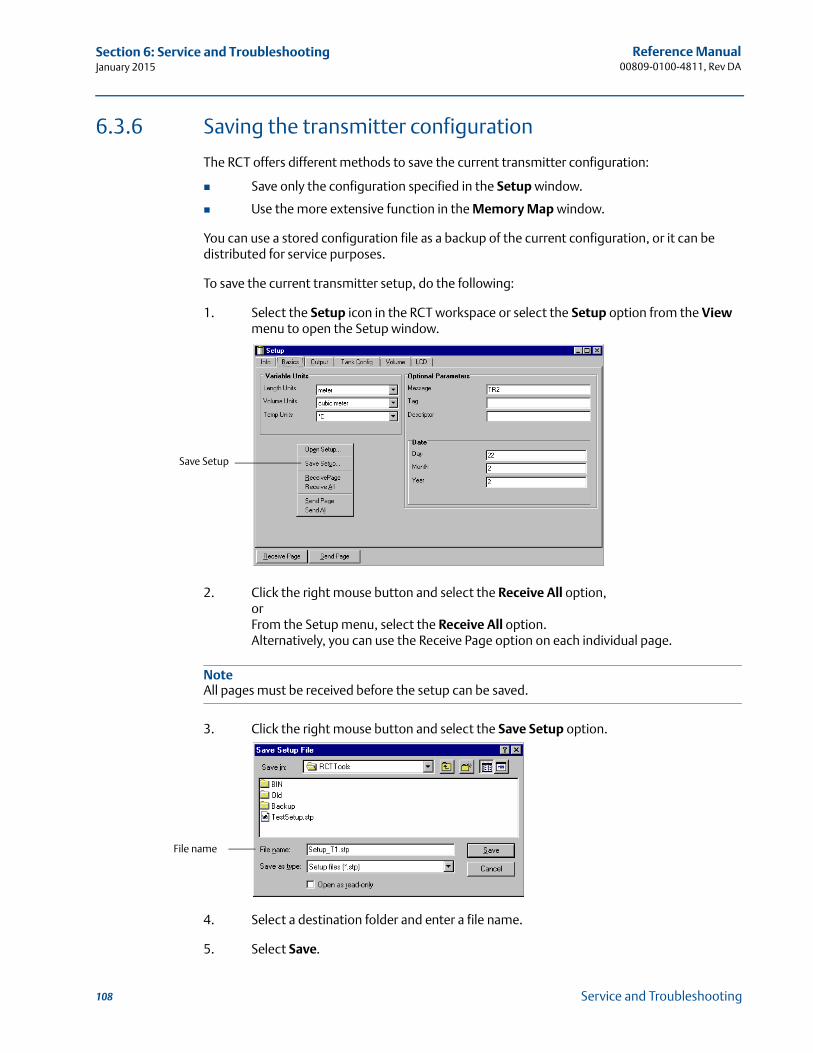
Reference Manual00809-0100-4811, Rev DA
Section 6: Service and TroubleshootingJanuary 2015
6.3.6 Saving the transmitter configuration
The RCT offers different methods to save the current transmitter configuration:
Save only the configuration specified in the Setup window.
Use the more extensive function in the Memory Map window.
You can use a stored configuration file as a backup of the current configuration, or it can be distributed for service purposes.
To save the current transmitter setup, do the following:
1. Select the Setup icon in the RCT workspace or select the Setup option from the View menu to open the Setup window.
2. Click the right mouse button and select the Receive All option,orFrom the Setup menu, select the Receive All option.Alternatively, you can use the Receive Page option on each individual page.
NoteAll pages must be received before the setup can be saved.
3. Click the right mouse button and select the Save Setup option.
4. Select a destination folder and enter a file name.
5. Select Save.
Save Setup
File name
108 Service and Troubleshooting
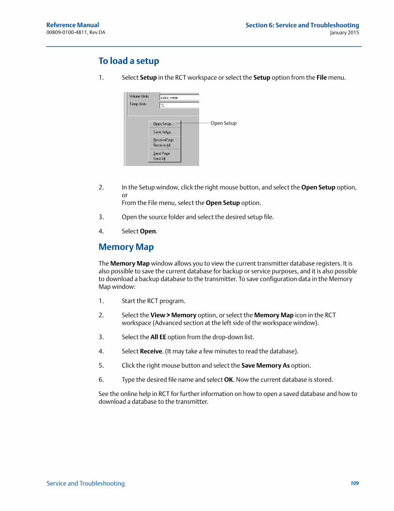
Reference Manual 00809-0100-4811, Rev DA
Section 6: Service and TroubleshootingJanuary 2015
To load a setup
1. Select Setup in the RCT workspace or select the Setup option from the File menu.
2. In the Setup window, click the right mouse button, and select the Open Setup option, orFrom the File menu, select the Open Setup option.
3. Open the source folder and select the desired setup file.
4. Select Open.
Memory Map
The Memory Map window allows you to view the current transmitter database registers. It is also possible to save the current database for backup or service purposes, and it is also possible to download a backup database to the transmitter. To save configuration data in the Memory Map window:
1. Start the RCT program.
2. Select the View > Memory option, or select the Memory Map icon in the RCT workspace (Advanced section at the left side of the workspace window).
3. Select the All EE option from the drop-down list.
4. Select Receive. (It may take a few minutes to read the database).
5. Click the right mouse button and select the Save Memory As option.
6. Type the desired file name and select OK. Now the current database is stored.
See the online help in RCT for further information on how to open a saved database and how to download a database to the transmitter.
Open Setup
109Service and Troubleshooting
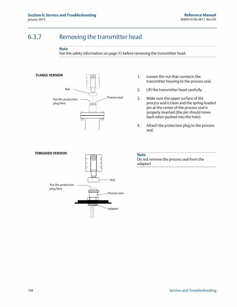
Reference Manual00809-0100-4811, Rev DA
Section 6: Service and TroubleshootingJanuary 2015
6.3.7 Removing the transmitter head
NoteSee the safety information on page 93 before removing the transmitter head.
1. Loosen the nut that connects the transmitter housing to the process seal.
2. Lift the transmitter head carefully.
3. Make sure the upper surface of the process seal is clean and the spring-loaded pin at the center of the process seal is properly inserted (the pin should move back when pushed into the hole).
4. Attach the protection plug to the process seal.
NoteDo not remove the process seal from the adapter!
Nut
Process sealPut the protection plug here
FLANGE VERSION
Nut
Process seal
Adapter
THREADED VERSION
Put the protection plug here
110 Service and Troubleshooting
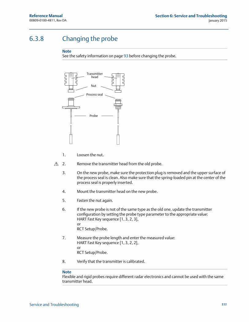
Reference Manual 00809-0100-4811, Rev DA
Section 6: Service and TroubleshootingJanuary 2015
6.3.8 Changing the probe
NoteSee the safety information on page 93 before changing the probe.
1. Loosen the nut.
2. Remove the transmitter head from the old probe.
3. On the new probe, make sure the protection plug is removed and the upper surface of the process seal is clean. Also make sure that the spring-loaded pin at the center of the process seal is properly inserted.
4. Mount the transmitter head on the new probe.
5. Fasten the nut again.
6. If the new probe is not of the same type as the old one, update the transmitter configuration by setting the probe type parameter to the appropriate value: HART Fast Key sequence [1, 3, 2, 3],orRCT Setup/Probe.
7. Measure the probe length and enter the measured value:HART Fast Key sequence [1, 3, 2, 2],orRCT Setup/Probe.
8. Verify that the transmitter is calibrated.
NoteFlexible and rigid probes require different radar electronics and cannot be used with the same transmitter head.
Nut
Probe
Transmitter head
Process seal
111Service and Troubleshooting
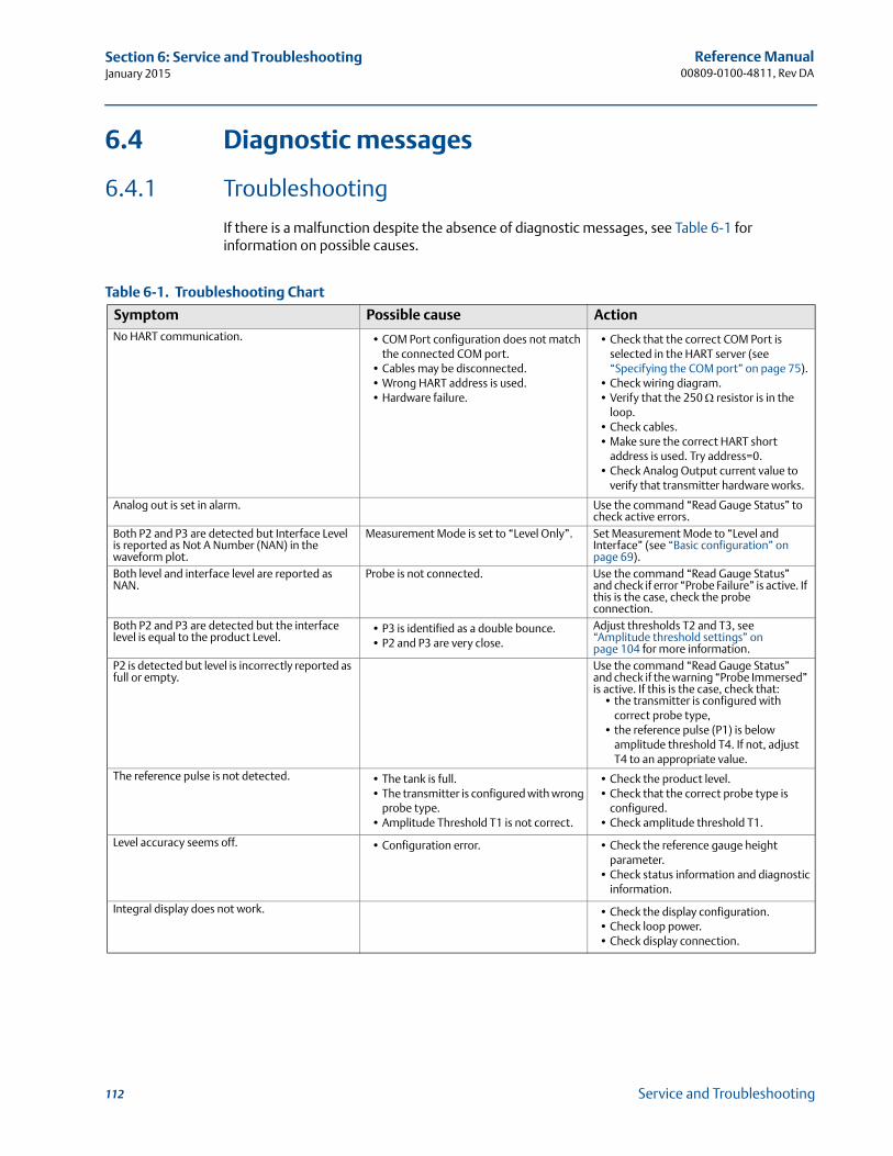
Reference Manual00809-0100-4811, Rev DA
Section 6: Service and TroubleshootingJanuary 2015
6.4 Diagnostic messages
6.4.1 Troubleshooting
If there is a malfunction despite the absence of diagnostic messages, see Table 6-1 for information on possible causes.
Table 6-1. Troubleshooting Chart
Symptom Possible cause ActionNo HART communication. • COM Port configuration does not match
the connected COM port.• Cables may be disconnected.• Wrong HART address is used.• Hardware failure.
• Check that the correct COM Port is selected in the HART server (see “Specifying the COM port” on page 75).
• Check wiring diagram.• Verify that the 250 resistor is in the
loop.• Check cables.• Make sure the correct HART short
address is used. Try address=0.• Check Analog Output current value to
verify that transmitter hardware works.
Analog out is set in alarm. Use the command “Read Gauge Status” to check active errors.
Both P2 and P3 are detected but Interface Level is reported as Not A Number (NAN) in the waveform plot.
Measurement Mode is set to “Level Only”. Set Measurement Mode to “Level and Interface” (see “Basic configuration” on page 69).
Both level and interface level are reported as NAN.
Probe is not connected. Use the command “Read Gauge Status” and check if error “Probe Failure” is active. If this is the case, check the probe connection.
Both P2 and P3 are detected but the interface level is equal to the product Level.
• P3 is identified as a double bounce.• P2 and P3 are very close.
Adjust thresholds T2 and T3, see “Amplitude threshold settings” on page 104 for more information.
P2 is detected but level is incorrectly reported as full or empty.
Use the command “Read Gauge Status” and check if the warning “Probe Immersed” is active. If this is the case, check that:
• the transmitter is configured with correct probe type,
• the reference pulse (P1) is below amplitude threshold T4. If not, adjust T4 to an appropriate value.
The reference pulse is not detected. • The tank is full.• The transmitter is configured with wrong
probe type.• Amplitude Threshold T1 is not correct.
• Check the product level.• Check that the correct probe type is
configured.• Check amplitude threshold T1.
Level accuracy seems off. • Configuration error. • Check the reference gauge height parameter.
• Check status information and diagnostic information.
Integral display does not work. • Check the display configuration.• Check loop power.• Check display connection.
112 Service and Troubleshooting
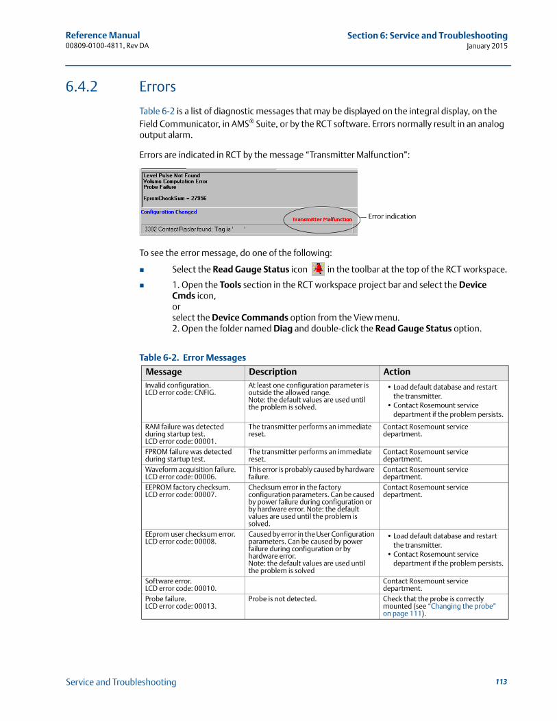
Reference Manual 00809-0100-4811, Rev DA
Section 6: Service and TroubleshootingJanuary 2015
6.4.2 Errors
Table 6-2 is a list of diagnostic messages that may be displayed on the integral display, on the Field Communicator, in AMS® Suite, or by the RCT software. Errors normally result in an analog output alarm.
Errors are indicated in RCT by the message “Transmitter Malfunction”:
To see the error message, do one of the following:
Select the Read Gauge Status icon in the toolbar at the top of the RCT workspace.
1. Open the Tools section in the RCT workspace project bar and select the Device Cmds icon, or select the Device Commands option from the View menu.2. Open the folder named Diag and double-click the Read Gauge Status option.
Table 6-2. Error Messages
Message Description ActionInvalid configuration.LCD error code: CNFIG.
At least one configuration parameter is outside the allowed range. Note: the default values are used until the problem is solved.
• Load default database and restart the transmitter.
• Contact Rosemount service department if the problem persists.
RAM failure was detected during startup test.LCD error code: 00001.
The transmitter performs an immediate reset.
Contact Rosemount service department.
FPROM failure was detected during startup test.
The transmitter performs an immediate reset.
Contact Rosemount service department.
Waveform acquisition failure.LCD error code: 00006.
This error is probably caused by hardware failure.
Contact Rosemount service department.
EEPROM factory checksum.LCD error code: 00007.
Checksum error in the factory configuration parameters. Can be caused by power failure during configuration or by hardware error. Note: the default values are used until the problem is solved.
Contact Rosemount service department.
EEprom user checksum error.LCD error code: 00008.
Caused by error in the User Configuration parameters. Can be caused by power failure during configuration or by hardware error.Note: the default values are used until the problem is solved
• Load default database and restart the transmitter.
• Contact Rosemount service department if the problem persists.
Software error.LCD error code: 00010.
Contact Rosemount service department.
Probe failure.LCD error code: 00013.
Probe is not detected. Check that the probe is correctly mounted (see “Changing the probe” on page 111).
Error indication
113Service and Troubleshooting
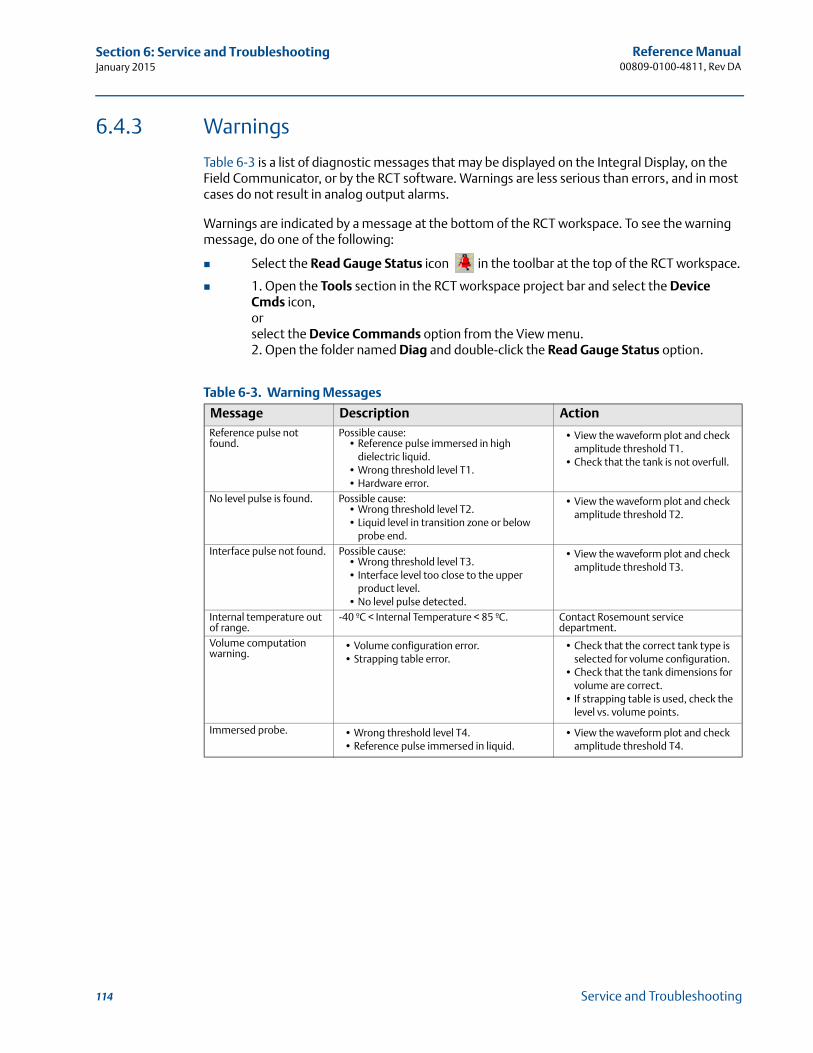
Reference Manual00809-0100-4811, Rev DA
Section 6: Service and TroubleshootingJanuary 2015
6.4.3 Warnings
Table 6-3 is a list of diagnostic messages that may be displayed on the Integral Display, on the Field Communicator, or by the RCT software. Warnings are less serious than errors, and in most cases do not result in analog output alarms.
Warnings are indicated by a message at the bottom of the RCT workspace. To see the warning message, do one of the following:
Select the Read Gauge Status icon in the toolbar at the top of the RCT workspace.
1. Open the Tools section in the RCT workspace project bar and select the Device Cmds icon, orselect the Device Commands option from the View menu.2. Open the folder named Diag and double-click the Read Gauge Status option.
Table 6-3. Warning Messages
Message Description ActionReference pulse not found.
Possible cause:• Reference pulse immersed in high
dielectric liquid.• Wrong threshold level T1.• Hardware error.
• View the waveform plot and check amplitude threshold T1.
• Check that the tank is not overfull.
No level pulse is found. Possible cause:• Wrong threshold level T2.• Liquid level in transition zone or below
probe end.
• View the waveform plot and check amplitude threshold T2.
Interface pulse not found. Possible cause:• Wrong threshold level T3.• Interface level too close to the upper
product level.• No level pulse detected.
• View the waveform plot and check amplitude threshold T3.
Internal temperature out of range.
-40 ºC < Internal Temperature < 85 ºC. Contact Rosemount service department.
Volume computation warning.
• Volume configuration error.• Strapping table error.
• Check that the correct tank type is selected for volume configuration.
• Check that the tank dimensions for volume are correct.
• If strapping table is used, check the level vs. volume points.
Immersed probe. • Wrong threshold level T4.• Reference pulse immersed in liquid.
• View the waveform plot and check amplitude threshold T4.
114 Service and Troubleshooting
Reference Manual 00809-0100-4811, Rev DA
Appendix A: Reference DataJanuary 2015
Appendix A Reference Data
Functional specification . . . . . . . . . . . . . . . . . . . . . . . . . . . . . . . . . . . . . . . . . . . . . . . . . . . . . . 115Performance specification . . . . . . . . . . . . . . . . . . . . . . . . . . . . . . . . . . . . . . . . . . . . . . . . . . . . 126Physical specification . . . . . . . . . . . . . . . . . . . . . . . . . . . . . . . . . . . . . . . . . . . . . . . . . . . . . . . . 132Dimensional drawings . . . . . . . . . . . . . . . . . . . . . . . . . . . . . . . . . . . . . . . . . . . . . . . . . . . . . . . 142Ordering information . . . . . . . . . . . . . . . . . . . . . . . . . . . . . . . . . . . . . . . . . . . . . . . . . . . . . . . . 152
A.1 Functional specification
A.1.1 General
Field of application
Liquids and semi-liquids level or liquid/liquid interfaces
Model 3301, for level or submerged probe interface measurement
Model 3302, for level and interface measurements
Measurement principle
Time Domain Reflectometry (TDR)
(See Figure 2-1 on page 7 for a description of how it works)
Microwave output power
Nominal 50 W, Max. 2 mW
Telecommunication (FCC and R&TTE)
FCC part 15 (1998) subpart B and R&TTE (EU directive 99/5/EC). The Rosemount 3300 Series is considered to be an unintentional radiator under the Part 15 rules.
Humidity
0 to 100% relative humidity
Start-up time
< 10 s
115Reference Data
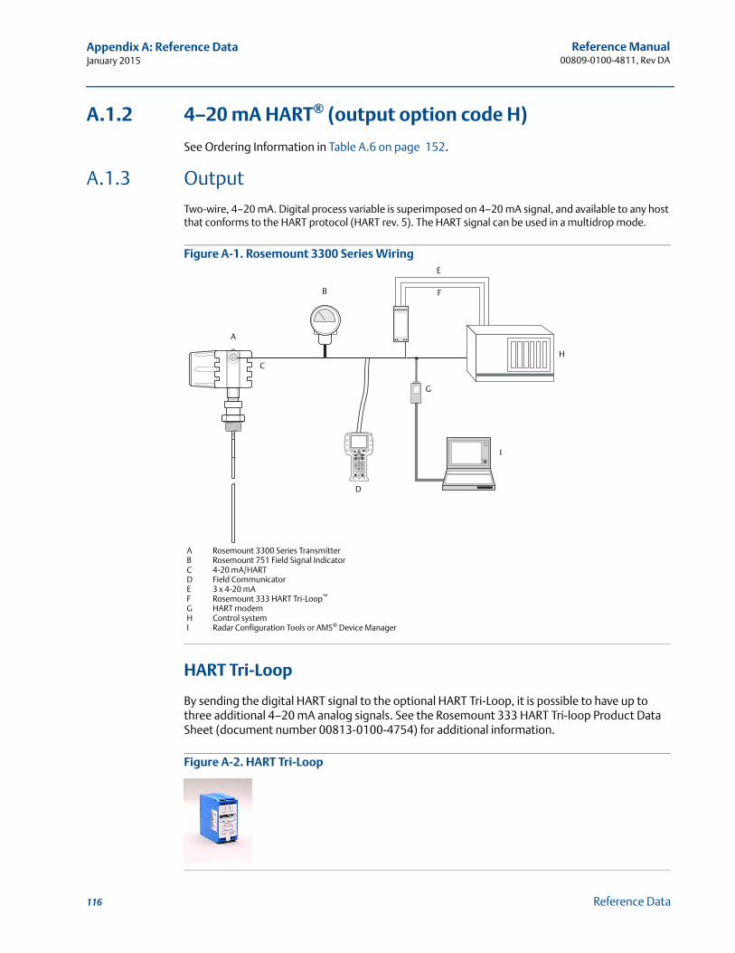
Reference Manual00809-0100-4811, Rev DA
Appendix A: Reference DataJanuary 2015
A.1.2 4–20 mA HART® (output option code H)
See Ordering Information in Table A.6 on page 152.
A.1.3 OutputTwo-wire, 4–20 mA. Digital process variable is superimposed on 4–20 mA signal, and available to any host that conforms to the HART protocol (HART rev. 5). The HART signal can be used in a multidrop mode.
Figure A-1. Rosemount 3300 Series Wiring
HART Tri-Loop
By sending the digital HART signal to the optional HART Tri-Loop, it is possible to have up to three additional 4–20 mA analog signals. See the Rosemount 333 HART Tri-loop Product Data Sheet (document number 00813-0100-4754) for additional information.
Figure A-2. HART Tri-Loop
A
B
C
D
I
F
E
H
G
A Rosemount 3300 Series TransmitterB Rosemount 751 Field Signal IndicatorC 4-20 mA/HARTD Field CommunicatorE 3 x 4-20 mAF Rosemount 333 HART Tri-Loop™
G HART modemH Control systemI Radar Configuration Tools or AMS® Device Manager
116 Reference Data

Reference Manual 00809-0100-4811, Rev DA
Appendix A: Reference DataJanuary 2015
Smart Wireless THUM™ adapter
The optional THUM adapter can be mounted directly on the transmitter or by using a remote mounting kit. IEC 62591 (WirelessHART) enables access to multi-variable data and diagnostics, and adds wireless to almost any measurement point. See the Rosemount Smart Wireless THUM adapter Product Data Sheet (document number 00813-0100-4075) and Smart Wireless THUM Adapter for Rosemount Process Level Transmitter Applications (document number 00840-0100-4026).
Figure A-3. Smart Wireless THUM Adapter
External power supply
The input voltage (Ui) for HART is 11 to 42 Vdc (11 to 30 Vdc in IS applications, and 16 to 42 Vdc in Explosion-proof/Flameproof applications).
For flameproof/explosion-proof installations the Rosemount 3300 Series Transmitters have a built-in barrier; no external barrier needed.
When a Smart Wireless THUM adapter is fitted, it adds a maximum drop of 2.5 Vdc in the connected loop.
R = load resistance ()
UE = external power supply voltage (Vdc)
UI = input voltage (Vdc)
Figure A-4. External Power Supply for HART
IS electrical parameters
Ui = 30 V, li = 130 mA, Pi = 1 W, Li = 0, Ci = 0
RUE
UI
117Reference Data
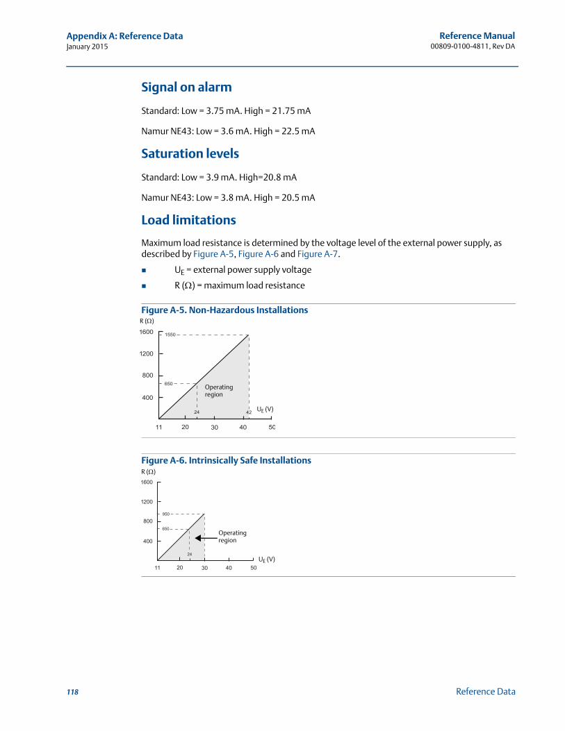
Reference Manual00809-0100-4811, Rev DA
Appendix A: Reference DataJanuary 2015
Signal on alarm
Standard: Low = 3.75 mA. High = 21.75 mA
Namur NE43: Low = 3.6 mA. High = 22.5 mA
Saturation levels
Standard: Low = 3.9 mA. High=20.8 mA
Namur NE43: Low = 3.8 mA. High = 20.5 mA
Load limitations
Maximum load resistance is determined by the voltage level of the external power supply, as described by Figure A-5, Figure A-6 and Figure A-7.
UE = external power supply voltage
R () = maximum load resistance
Figure A-5. Non-Hazardous Installations
Figure A-6. Intrinsically Safe Installations
R ()
UE (V)
Operating region
R ()
UE (V)
Operating region
118 Reference Data
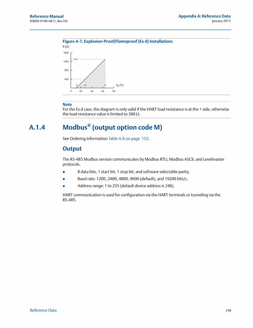
Reference Manual 00809-0100-4811, Rev DA
Appendix A: Reference DataJanuary 2015
Figure A-7. Explosion-Proof/Flameproof (Ex d) Installations
NoteFor the Ex d case, the diagram is only valid if the HART load resistance is at the + side, otherwise the load resistance value is limited to 300
A.1.4 Modbus® (output option code M)
See Ordering Information Table A.6 on page 152.
Output
The RS-485 Modbus version communicates by Modbus RTU, Modbus ASCII, and Levelmaster protocols.
8 data bits, 1 start bit, 1 stop bit, and software selectable parity.
Baud rate: 1200, 2400, 4800, 9600 (default), and 19200 bits/s.
Address range: 1 to 255 (default device address is 246).
HART communication is used for configuration via the HART terminals or tunneling via the RS-485.
UE (V)
R ()
119Reference Data
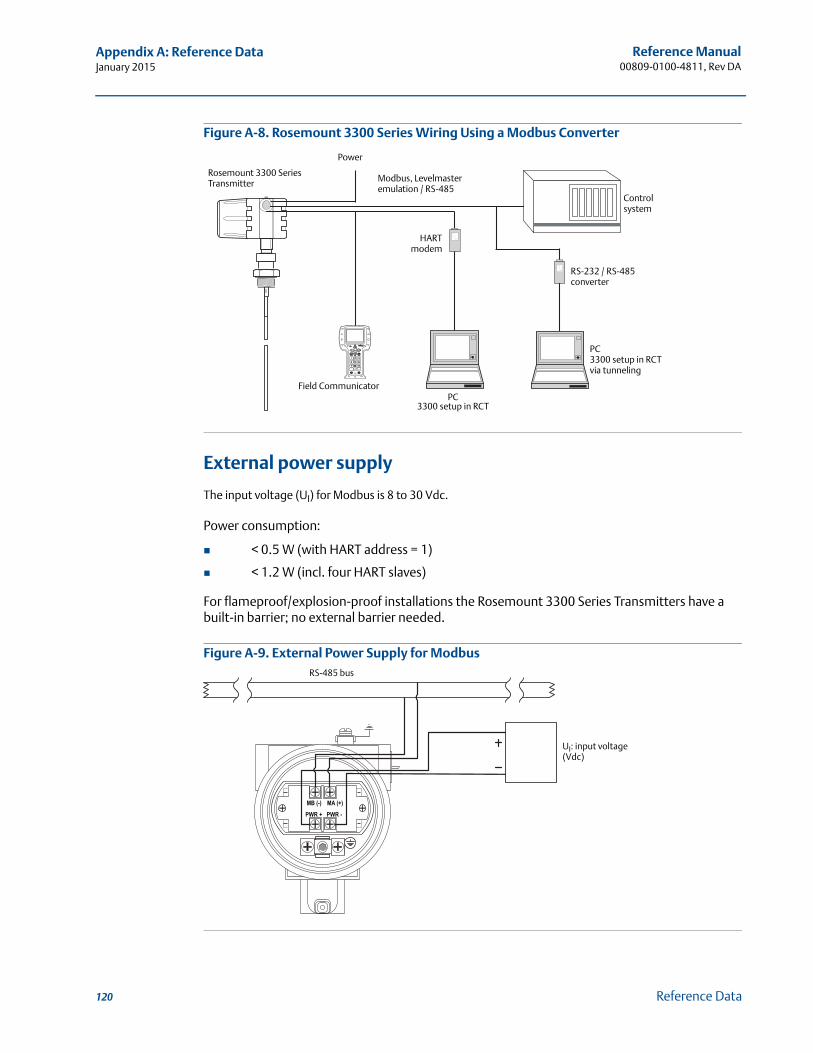
Reference Manual00809-0100-4811, Rev DA
Appendix A: Reference DataJanuary 2015
Figure A-8. Rosemount 3300 Series Wiring Using a Modbus Converter
External power supply
The input voltage (UI) for Modbus is 8 to 30 Vdc.
Power consumption:
< 0.5 W (with HART address = 1)
< 1.2 W (incl. four HART slaves)
For flameproof/explosion-proof installations the Rosemount 3300 Series Transmitters have a built-in barrier; no external barrier needed.
Figure A-9. External Power Supply for Modbus
Rosemount 3300 Series Transmitter
Control system
HARTmodem
PC 3300 setup in RCT via tunneling
Power
Field Communicator
Modbus, Levelmaster emulation / RS-485
PC3300 setup in RCT
RS-232 / RS-485converter
RS-485 bus
UI: input voltage (Vdc)
120 Reference Data
Reference Manual 00809-0100-4811, Rev DA
Appendix A: Reference DataJanuary 2015
A.1.5 Display and configuration
Integral display (option code M1)
The integral display toggles between the following variables:
level
distance
volume
internal temperature
interface distance
interface level
peak amplitudes
interface thickness
percent of range
analog current output
NoteThe integral display cannot be used to configure the transmitter.
Remote display
Data can be read remotely by using the four-digit Rosemount 751 Field Signal Indicator. For further information, see the Rosemount 751 Product Data Sheet (document number 00813-0100-4378).
Configuration tools
Emerson Field Communicator (e.g. 375/475 Field Communicator), Radar Configuration Tools (RCT) software package for PC (included with delivery of transmitter), or Emerson AMS Device Manager for PC, or DeltaV™, or any other DD (Device Description) compatible host systems.
DTM (compliant with version 1.2 of the FDT/DTM specification) is also available supporting configuration in for instance Yokogawa® Fieldmate/PRM, E+H™ FieldCare, and PactWare™
To communicate using RCT or AMS Device Manager, a HART modem is required. The HART modem is available as an RS232 or USB version (see page 152)
The transmitter can be pre-configured by selecting Options, Option Code C1 (page 156) and sending a completed Configuration Data Sheet (CDS). The CDS is available from www.rosemount.com.
121Reference Data
Reference Manual00809-0100-4811, Rev DA
Appendix A: Reference DataJanuary 2015
Output units
For level interface, and distance:
ft
inch
m
cm
mm
For volume:
ft3
inch3
US gals
Imp gals
barrels
yd3
m3
liters
Output variables
Rosemount 3301:
level
distance (to product surface)
volume
internal temperature
peak amplitudes
For submerged probe interface measurements:
interface level
interface distance)
Rosemount 3302:
level
distance (to product surface)
volume
interface level
interface distance
upper product thickness
internal temperature
peak amplitudes
122 Reference Data
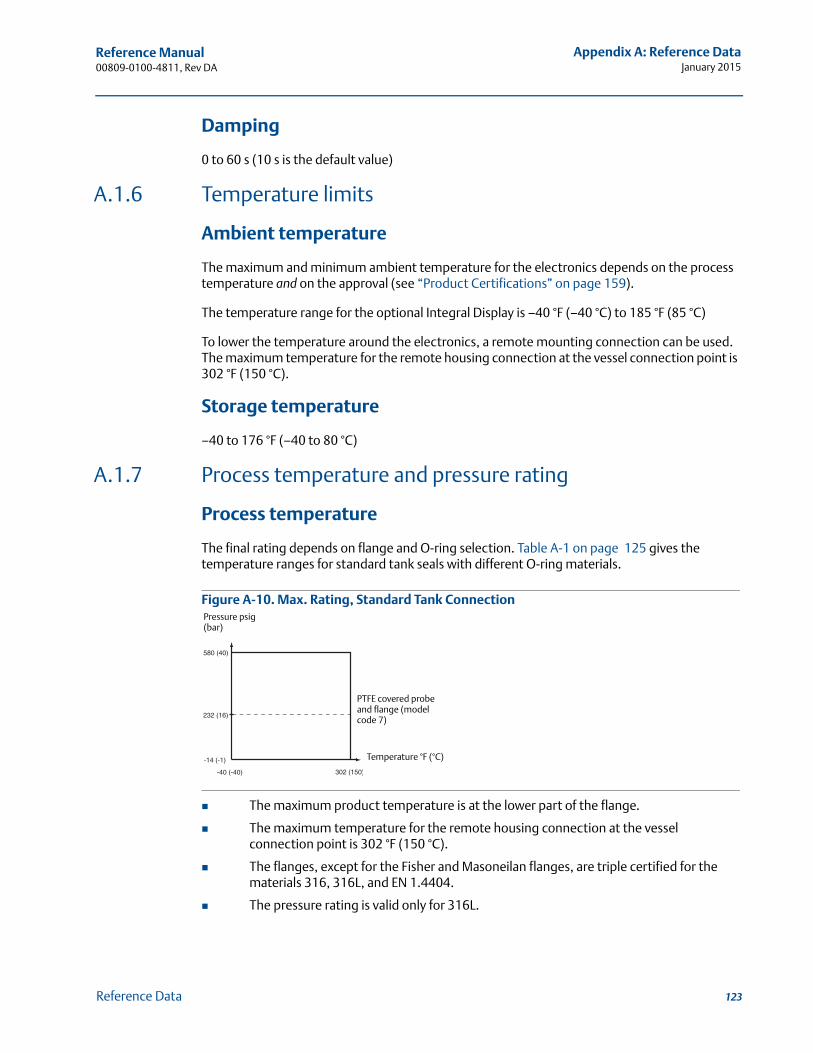
Reference Manual 00809-0100-4811, Rev DA
Appendix A: Reference DataJanuary 2015
Damping
0 to 60 s (10 s is the default value)
A.1.6 Temperature limits
Ambient temperature
The maximum and minimum ambient temperature for the electronics depends on the process temperature and on the approval (see “Product Certifications” on page 159).
The temperature range for the optional Integral Display is –40 °F (–40 °C) to 185 °F (85 °C)
To lower the temperature around the electronics, a remote mounting connection can be used. The maximum temperature for the remote housing connection at the vessel connection point is 302 °F (150 °C).
Storage temperature
–40 to 176 °F (–40 to 80 °C)
A.1.7 Process temperature and pressure rating
Process temperature
The final rating depends on flange and O-ring selection. Table A-1 on page 125 gives the temperature ranges for standard tank seals with different O-ring materials.
Figure A-10. Max. Rating, Standard Tank Connection
The maximum product temperature is at the lower part of the flange.
The maximum temperature for the remote housing connection at the vessel connection point is 302 °F (150 °C).
The flanges, except for the Fisher and Masoneilan flanges, are triple certified for the materials 316, 316L, and EN 1.4404.
The pressure rating is valid only for 316L.
Pressure psig (bar)
Temperature °F (°C)
PTFE covered probe and flange (model code 7)
123Reference Data

Reference Manual00809-0100-4811, Rev DA
Appendix A: Reference DataJanuary 2015
ASME / ANSI flange rating
316 and 316L SST flanges according to ASME B16.5 Table 2-2.3. Max. 302 °F/580 psig (150 °C/40 bar).
EN flange rating
1.4404 according to EN 1092-1 material group 13E0. Max. 302 °F/580 psig (150 °C/40 bar).
Fisher & Masoneilan flange rating
316 and 316L SST flanges according to ASME B16.5 Table 2-2.3. Max. 302 °F/580 psig (150 °C/40 bar).
JIS flange rating
316 and 316L SST flanges according to JIS B2220 material group 2.3. Max. 302 °F/580 psig (150 °C/40 bar).
Tri-Clamp rating
Maximum pressure is 16 bar for 11/2-in. (37.5 mm) and 2-in. (50 mm) housing; and 10 bar for 3-in. (75 mm) and 4-in. (100 mm) housing. The final rating depends on the clamp and gasket.
Plate design
Certain models of flanged Alloy and PTFE covered probes have a tank connection design with a protective flange plate of the same material as the probe and with a backing flange in 316 or 316L / EN 1.4404. The protective flange plate prevents the backing flange from being exposed to the tank atmosphere.
For Alloy C-276 and Alloy 400, probes with flange plate design are available up to Class 300/PN 40.
For PTFE, probes with flange plate design are available up to Class 150/PN 16.
Flange connection rating
See Table A-2 for the conditions used for flange strength calculations.
A.1.8 Interface measurements
Considerations
The Rosemount 3302 is a good choice for measuring the interface of oil and water, or other liquids with significant dielectric differences. It is also possible to measure interfaces with a
124 Reference Data
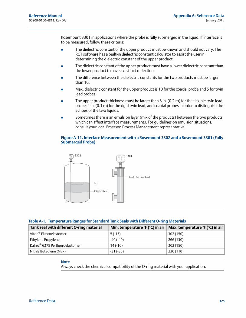
Reference Manual 00809-0100-4811, Rev DA
Appendix A: Reference DataJanuary 2015
Rosemount 3301 in applications where the probe is fully submerged in the liquid. If interface is to be measured, follow these criteria:
The dielectric constant of the upper product must be known and should not vary. The RCT software has a built-in dielectric constant calculator to assist the user in determining the dielectric constant of the upper product.
The dielectric constant of the upper product must have a lower dielectric constant than the lower product to have a distinct reflection.
The difference between the dielectric constants for the two products must be larger than 10.
Max. dielectric constant for the upper product is 10 for the coaxial probe and 5 for twin lead probes.
The upper product thickness must be larger than 8 in. (0.2 m) for the flexible twin lead probe; 4 in. (0.1 m) for the rigid twin lead, and coaxial probes in order to distinguish the echoes of the two liquids.
Sometimes there is an emulsion layer (mix of the products) between the two products which can affect interface measurements. For guidelines on emulsion situations, consult your local Emerson Process Management representative.
Figure A-11. Interface Measurement with a Rosemount 3302 and a Rosemount 3301 (Fully Submerged Probe)
Table A-1. Temperature Ranges for Standard Tank Seals with Different O-ring Materials
NoteAlways check the chemical compatibility of the O-ring material with your application.
Tank seal with different O-ring material Min. temperature °F (°C) in air Max. temperature °F (°C) in air
Viton® Fluoroelastomer 5 (-15) 302 (150)
Ethylene Propylene -40 (-40) 266 (130)
Kalrez® 6375 Perfluoroelastomer 14 (-10) 302 (150)
Nitrile Butadiene (NBR) -31 (-35) 230 (110)
Level
Interface Level
Level = Interface Level
3302 3301
125Reference Data
Reference Manual00809-0100-4811, Rev DA
Appendix A: Reference DataJanuary 2015
A.2 Performance specification
A.2.1 General
Reference conditions
Twin lead probe, 77 °F (25 °C) water
Reference accuracy ± 0.2 in. (5 mm) for probes <16.4 ft. (5 m)
± 0.1% of measured distance for rigid probes >16.4 ft. (5 m)
± 0.15% of measured distance for flexible probes >16.4 ft. (5 m)
Repeatability
± 0.04 in. (1 mm)
Ambient temperature effect
Less than 0.01% of measured distance per °C
Update interval
1 per second
A.2.2 Measuring range
Transition zones
These zones are areas where measurements are non-linear or have reduced accuracy. If measurements are desired at the very top of a tank, it is possible to mechanically extend the nozzle and use a coaxial probe. The upper transition zone is then moved into the extension. See Table A-3 on page 127.
Table A-2. Conditions Used for Flange Strength Calculations
Bolting material Gasket Flange material Hub material
ASME / ANSI SST SA193 B8M Class 2 Soft (1a) with min. thickness 1.6 mm SST A182
Gr. F316L and EN 10222-5-1.4404
SST SA479M 316L and EN 10272-1.4404EN, JIS EN 1515-1/-2 group 13E0,
A4-70Soft (EN 1514-1) with min. thickness 1.6 mm
126 Reference Data
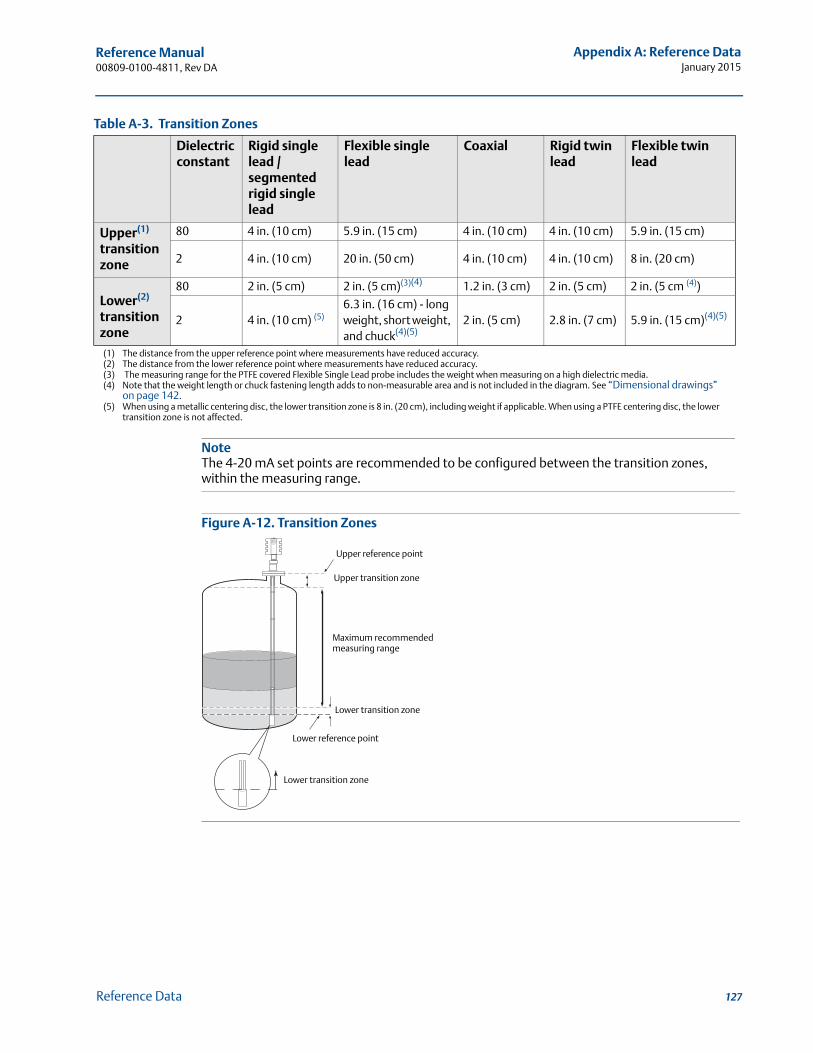
Reference Manual 00809-0100-4811, Rev DA
Appendix A: Reference DataJanuary 2015
Table A-3. Transition Zones
Figure A-12. Transition Zones
Dielectric constant
Rigid single lead / segmented rigid single lead
Flexible single lead
Coaxial Rigid twin lead
Flexible twin lead
Upper(1)
transition zone
(1) The distance from the upper reference point where measurements have reduced accuracy.
80 4 in. (10 cm) 5.9 in. (15 cm) 4 in. (10 cm) 4 in. (10 cm) 5.9 in. (15 cm)
2 4 in. (10 cm) 20 in. (50 cm) 4 in. (10 cm) 4 in. (10 cm) 8 in. (20 cm)
Lower(2)
transition zone
(2) The distance from the lower reference point where measurements have reduced accuracy.
80 2 in. (5 cm) 2 in. (5 cm)(3)(4)
(3) The measuring range for the PTFE covered Flexible Single Lead probe includes the weight when measuring on a high dielectric media.
1.2 in. (3 cm) 2 in. (5 cm) 2 in. (5 cm (4))
(4) Note that the weight length or chuck fastening length adds to non-measurable area and is not included in the diagram. See “Dimensional drawings” on page 142.
2 4 in. (10 cm) (5)
(5) When using a metallic centering disc, the lower transition zone is 8 in. (20 cm), including weight if applicable. When using a PTFE centering disc, the lower transition zone is not affected.
NoteThe 4-20 mA set points are recommended to be configured between the transition zones, within the measuring range.
6.3 in. (16 cm) - long weight, short weight, and chuck(4)(5)
2 in. (5 cm) 2.8 in. (7 cm) 5.9 in. (15 cm)(4)(5)
Upper reference point
Upper transition zone
Maximum recommendedmeasuring range
Lower transition zone
Lower reference point
Lower transition zone
127Reference Data
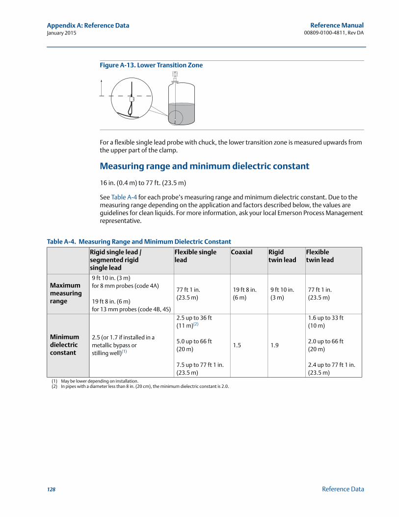
Reference Manual00809-0100-4811, Rev DA
Appendix A: Reference DataJanuary 2015
Figure A-13. Lower Transition Zone
For a flexible single lead probe with chuck, the lower transition zone is measured upwards from the upper part of the clamp.
Measuring range and minimum dielectric constant
16 in. (0.4 m) to 77 ft. (23.5 m)
See Table A-4 for each probe’s measuring range and minimum dielectric constant. Due to the measuring range depending on the application and factors described below, the values are guidelines for clean liquids. For more information, ask your local Emerson Process Management representative.
Table A-4. Measuring Range and Minimum Dielectric Constant
Rigid single lead / segmented rigid single lead
Flexible single lead
Coaxial Rigid twin lead
Flexible twin lead
Maximum measuring range
9 ft 10 in. (3 m) for 8 mm probes (code 4A)
19 ft 8 in. (6 m) for 13 mm probes (code 4B, 4S)
77 ft 1 in. (23.5 m)
19 ft 8 in. (6 m)
9 ft 10 in. (3 m)
77 ft 1 in. (23.5 m)
Minimum dielectric constant
2.5 (or 1.7 if installed in a metallic bypass orstilling well)(1)
(1) May be lower depending on installation.
2.5 up to 36 ft (11 m)(2)
5.0 up to 66 ft (20 m)
7.5 up to 77 ft 1 in. (23.5 m)
(2) In pipes with a diameter less than 8 in. (20 cm), the minimum dielectric constant is 2.0.
1.5 1.9
1.6 up to 33 ft (10 m)
2.0 up to 66 ft (20 m)
2.4 up to 77 ft 1 in. (23.5 m)
128 Reference Data
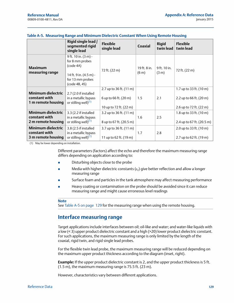
Reference Manual 00809-0100-4811, Rev DA
Appendix A: Reference DataJanuary 2015
Table A-5. Measuring Range and Minimum Dielectric Constant When Using Remote Housing
Different parameters (factors) affect the echo and therefore the maximum measuring range differs depending on application according to:
Disturbing objects close to the probe
Media with higher dielectric constants (r) give better reflection and allow a longer measuring range
Surface foam and particles in the tank atmosphere may affect measuring performance
Heavy coating or contamination on the probe should be avoided since it can reduce measuring range and might cause erroneous level readings
NoteSee Table A-5 on page 129 for the measuring range when using the remote housing.
Interface measuring range
Target applications include interfaces between oil; oil-like and water; and water-like liquids with a low (< 3) upper product dielectric constant and a high (>20) lower product dielectric constant. For such applications, the maximum measuring range is only limited by the length of the coaxial, rigid twin, and rigid single lead probes.
For the flexible twin lead probe, the maximum measuring range will be reduced depending on the maximum upper product thickness according to the diagram (inset, right).
Example: If the upper product dielectric constant is 2, and the upper product thickness is 5 ft. (1.5 m), the maximum measuring range is 75.5 ft. (23 m).
However, characteristics vary between different applications.
Rigid single lead / segmented rigid single lead
Flexible single lead
CoaxialRigid twin lead
Flexible twin lead
Maximum measuring range
9 ft. 10 in. (3 m) - for 8 mm probes (code 4A)
14 ft. 9 in. (4.5 m) - for 13 mm probes (code 4B, 4S)
72 ft. (22 m)19 ft. 8 in. (6 m)
9 ft. 10 in. (3 m)
72 ft. (22 m)
Minimum dielectric constant with 1 m remote housing
2.7 (2.0 if installed in a metallic bypass or stilling well)(1)
(1) May be lower depending on installation.
2.7 up to 36 ft. (11 m)
6 up to 66 ft. (20 m)
10 up to 72 ft. (22 m)
1.5 2.1
1.7 up to 33 ft. (10 m)
2.2 up to 66 ft. (20 m)
2.6 up to 72 ft. (22 m)
Minimum dielectric constant with 2 m remote housing
3.3 (2.2 if installed in a metallic bypass or stilling well)(1)
3.2 up to 36 ft. (11 m)
8 up to 67 ft. (20.5 m)1.6 2.5
1.8 up to 33 ft. (10 m)
2.4 up to 67 ft. (20.5 m)
Minimum dielectric constant with 3 m remote housing
3.8 (2.5 if installed in a metallic bypass or stilling well)(1)
3.7 up to 36 ft. (11 m)
11 up to 62 ft. (19 m)1.7 2.8
2.0 up to 33 ft. (10 m)
2.7 up to 62 ft. (19 m)
129Reference Data
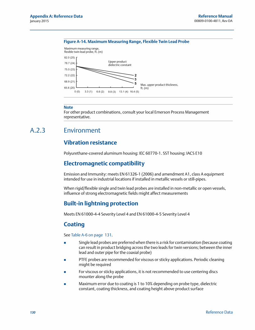
Reference Manual00809-0100-4811, Rev DA
Appendix A: Reference DataJanuary 2015
Figure A-14. Maximum Measuring Range, Flexible Twin Lead Probe
NoteFor other product combinations, consult your local Emerson Process Management representative.
A.2.3 Environment
Vibration resistance
Polyurethane-covered aluminum housing: IEC 60770-1. SST housing: IACS E10
Electromagnetic compatibility
Emission and Immunity: meets EN 61326-1 (2006) and amendment A1, class A equipment intended for use in industrial locations if installed in metallic vessels or still-pipes.
When rigid/flexible single and twin lead probes are installed in non-metallic or open vessels, influence of strong electromagnetic fields might affect measurements
Built-in lightning protection
Meets EN 61000-4-4 Severity Level 4 and EN 61000-4-5 Severity Level 4
Coating
See Table A-6 on page 131.
Single lead probes are preferred when there is a risk for contamination (because coating can result in product bridging across the two leads for twin versions; between the inner lead and outer pipe for the coaxial probe)
PTFE probes are recommended for viscous or sticky applications. Periodic cleaning might be required
For viscous or sticky applications, it is not recommended to use centering discs mounter along the probe
Maximum error due to coating is 1 to 10% depending on probe type, dielectric constant, coating thickness, and coating height above product surface
82.0 (25)
78.7 (24)
75.5 (23)
72.2 (22)
68.9 (21)
65.6 (20)
0 (0) 3.3 (1) 6.6 (2) 9.8 (3) 13.1 (4) 16.4 (5)
Upper product dielectric constant
Max. upper product thickness,ft. (m)
235
Maximum measuring range, flexible twin lead probe, ft. (m)
130 Reference Data
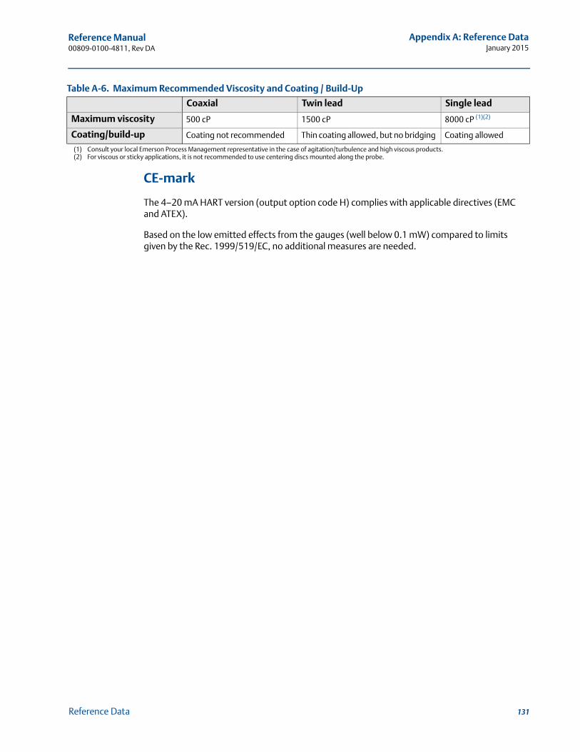
Reference Manual 00809-0100-4811, Rev DA
Appendix A: Reference DataJanuary 2015
Table A-6. Maximum Recommended Viscosity and Coating / Build-Up
CE-mark
The 4–20 mA HART version (output option code H) complies with applicable directives (EMC and ATEX).
Based on the low emitted effects from the gauges (well below 0.1 mW) compared to limits given by the Rec. 1999/519/EC, no additional measures are needed.
Coaxial Twin lead Single lead
Maximum viscosity 500 cP 1500 cP 8000 cP (1)(2)
(1) Consult your local Emerson Process Management representative in the case of agitation/turbulence and high viscous products.(2) For viscous or sticky applications, it is not recommended to use centering discs mounted along the probe.
Coating/build-up Coating not recommended Thin coating allowed, but no bridging Coating allowed
131Reference Data

Reference Manual00809-0100-4811, Rev DA
Appendix A: Reference DataJanuary 2015
A.3 Physical specification
A.3.1 Material selection
Emerson provides a variety of Rosemount product with various product options and configurations including materials of construction that can be expected to perform well in a wide range of applications. The Rosemount product information presented is intended as a guide for the purchaser to make an appropriate selection for the application. It is the purchaser’s sole responsibility to make a careful analysis of all process parameters (such as all chemical components, temperature, pressure, flow rate, abrasives, contaminants, etc.), when specifying product, materials, options and components for the particular application. Emerson Process Management is not in a position to evaluate or guarantee the compatibility of the process fluid or other process parameters with the product, options, configuration or materials of construction selected.
A.3.2 Housing and enclosure
Type
Dual compartment (removable without opening the tank). Electronics and cabling are separated.
Two entries for conduit or cable connections. The transmitter housing can be rotated in any direction.
Electrical connection
½ - 14 NPT for cable glands or conduit entries.
Optional: M20 x 1.5 conduit/cable adapter or PG 13.5 conduit/cable adapter.
Recommended output cabling is twisted shielded pairs, 18-12 AWG.
Housing material
Polyurethane-covered aluminum or SST Grade CF8M (ASTM A743)
Ingress protection
NEMA 4X, IP 66, IP 67
Factory sealed
Yes
Weight
Transmitter head (TH): 5.5 lb (2.5 kg) in aluminum, 11 lb (5 kg) in SST
132 Reference Data
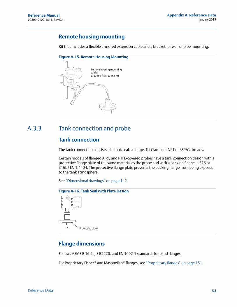
Reference Manual 00809-0100-4811, Rev DA
Appendix A: Reference DataJanuary 2015
Remote housing mounting
Kit that includes a flexible armored extension cable and a bracket for wall or pipe mounting.
Figure A-15. Remote Housing Mounting
A.3.3 Tank connection and probe
Tank connection
The tank connection consists of a tank seal, a flange, Tri-Clamp, or NPT or BSP/G threads.
Certain models of flanged Alloy and PTFE-covered probes have a tank connection design with a protective flange plate of the same material as the probe and with a backing flange in 316 or 316L / EN 1.4404. The protective flange plate prevents the backing flange from being exposed to the tank atmosphere.
See “Dimensional drawings” on page 142.
Figure A-16. Tank Seal with Plate Design
Flange dimensions
Follows ASME B 16.5, JIS B2220, and EN 1092-1 standards for blind flanges.
For Proprietary Fisher® and Masoneilan® flanges, see “Proprietary flanges” on page 151.
Remote housing mounting cable:3, 6, or 9 ft (1, 2, or 3 m)
Protective plate
133Reference Data
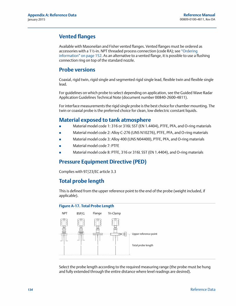
Reference Manual00809-0100-4811, Rev DA
Appendix A: Reference DataJanuary 2015
Vented flanges
Available with Masoneilan and Fisher vented flanges. Vented flanges must be ordered as accessories with a 1½-in. NPT threaded process connection (code RA); see “Ordering information” on page 152. As an alternative to a vented flange, it is possible to use a flushing connection ring on top of the standard nozzle.
Probe versions
Coaxial, rigid twin, rigid single and segmented rigid single lead, flexible twin and flexible single lead.
For guidelines on which probe to select depending on application, see the Guided Wave Radar Application Guidelines Technical Note (document number 00840-2600-4811).
For interface measurements the rigid single probe is the best choice for chamber mounting. The twin or coaxial probe is the preferred choice for clean, low dielectric constant liquids.
Material exposed to tank atmosphere Material model code 1: 316 or 316L SST (EN 1.4404), PTFE, PFA, and O-ring materials
Material model code 2: Alloy C-276 (UNS N10276), PTFE, PFA, and O-ring materials
Material model code 3: Alloy 400 (UNS N04400), PTFE, PFA, and O-ring materials
Material model code 7: PTFE
Material model code 8: PTFE, 316 or 316L SST (EN 1.4404), and O-ring materials
Pressure Equipment Directive (PED)
Complies with 97/23/EC article 3.3
Total probe length
This is defined from the upper reference point to the end of the probe (weight included, if applicable).
Figure A-17. Total Probe Length
Select the probe length according to the required measuring range (the probe must be hung and fully extended through the entire distance where level readings are desired).
Total probe length
NPT BSP/G Flange Tri-Clamp
Upper reference point
134 Reference Data
Reference Manual 00809-0100-4811, Rev DA
Appendix A: Reference DataJanuary 2015
Cut-to-fit probes
Most of the probes can be cut in field. However, there are some restrictions for the standard coaxial probes: these can be cut up to 2 ft. (0.6 m). Probes shorter than 4.1 ft. (1.25 m) can be cut to the minimum length of 1.3 ft. (0.4 m). The PTFE covered probes cannot be cut in the field. For flexible twin lead probes, the minimum length is 3.3 ft. (1 m).
Minimum and maximum probe length
Coaxial: 1.3 ft (0.4 m) to 19.7 ft (6 m)
Rigid twin lead: 1.3 ft (0.4 m) to 9.8 ft (3 m)
Flexible twin lead: 3.3 ft (1 m) to 77.1 ft (23.5 m)
Rigid single lead (0.3 in./8 mm): 1.3 ft (0.4 m) to 9.8 ft (3 m)
Rigid single lead (0.5 in./13 mm): 1.3 ft (0.4 m) to 19.7 ft (6.0 m)
Segmented rigid single lead (0.5 in./13 mm): 1.3 ft (0.4 m) to 19.7 ft (6 m)
Flexible single lead: 3.3 ft (1 m) to 77.1 ft (23.5 m)
Probe angle
0 to 90 degrees from vertical axis
Tensile strength Flexible single lead probe: 2698 lb (12 kN)
Flexible twin lead probe: 2023 lb (9 kN)
Collapse load
Flexible single lead probe: 3597 lb (16 kN)
Sideway capacity
Coaxial probe: 73.7 ft. lbf, 3.7 lb at 19.7 ft. (100 Nm, 1.67 kg at 6 m)
Rigid twin lead: 2.2 ft. lbf, 0.22 lb at 9.8 ft. (3 Nm, 0.1 kg at 3 m)
Rigid single lead / segmented rigid single lead: 4.4 ft. lbf, 0.44 lb at 9.8 ft. (6 Nm, 0.2 kg at 3 m)
Maximum recommended nozzle height
4 in. (10 cm) + nozzle diameter
For coaxial probes, there are no restrictions.
Minimum clearance
See Table A-7 on page 140.
135Reference Data
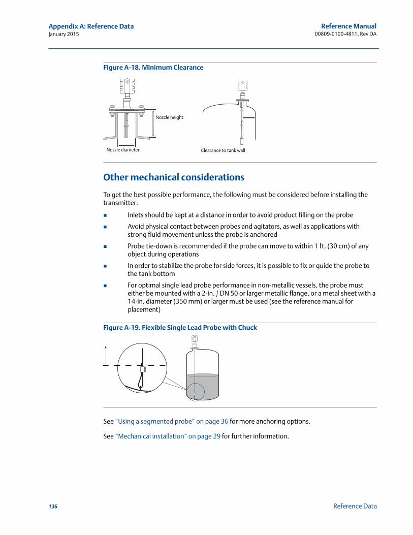
Reference Manual00809-0100-4811, Rev DA
Appendix A: Reference DataJanuary 2015
Figure A-18. Minimum Clearance
Other mechanical considerations
To get the best possible performance, the following must be considered before installing the transmitter:
Inlets should be kept at a distance in order to avoid product filling on the probe
Avoid physical contact between probes and agitators, as well as applications with strong fluid movement unless the probe is anchored
Probe tie-down is recommended if the probe can move to within 1 ft. (30 cm) of any object during operations
In order to stabilize the probe for side forces, it is possible to fix or guide the probe to the tank bottom
For optimal single lead probe performance in non-metallic vessels, the probe must either be mounted with a 2-in. / DN 50 or larger metallic flange, or a metal sheet with a 14-in. diameter (350 mm) or larger must be used (see the reference manual for placement)
Figure A-19. Flexible Single Lead Probe with Chuck
See “Using a segmented probe” on page 36 for more anchoring options.
See “Mechanical installation” on page 29 for further information.
Nozzle diameter
Nozzle height
Clearance to tank wall
136 Reference Data

Reference Manual 00809-0100-4811, Rev DA
Appendix A: Reference DataJanuary 2015
Weight
Flange: depends on flange size
Coaxial probe: 0.67 lb/ft. (1 kg/m)
Rigid single lead probe (0.3 in./8 mm): 0.27 lb/ft. (0.4 kg/m)
Rigid single lead probe (0.5 in./13 mm): 0.71 lb/ft. (1.06 kg/m)
Segmented Rigid Single Lead probe (0.5 in./13 mm): 0.71 lb/ft (1.06 kg/m)
Rigid twin lead probe: 0.40 lb/ft. (0.6 kg/m)
Flexible single lead probe: 0.05 lb/ft. (0.07 kg/m)
Flexible twin lead probe: 0.09 lb/ft. (0.14 kg/m)
End weight: 0.88 lb (0.40 kg) for single probes, 1.3 lb (0.60 kg) for twin probes
Engineered solutions
When standard model codes are not sufficient to fulfil requirements, please consult the factory to explore possible Engineered Solutions. This is typically, but not exclusively, related to the choice of wetted materials or the design of a process connection. These Engineered Solutions are part of the expanded offerings and may be subject to additional delivery lead time. For ordering, factory will supply a special R-labeled numeric option code that should be added at the end of the standard model string. See example model string below.
Example Model String: 3301-H-A-1-S-1-V-5A-E-33-00-RC-I5-M1W3C1-R1234
A.3.4 Chamber / pipe installations
Rosemount 9901 chamber
Rosemount 9901 allows external mounting of process level instrumentation. It supports a variety of process connections, and optional drain and vent connections. The Rosemount 9901 chamber is designed to the ASME B31.3 standard, and is Pressure Equipment Directive (PED) compliant. Use option code XC to order together with the 3300 Series transmitters.
The probe length to use for a Rosemount 9901 chamber can be calculated with this formula:
Side-and-side dimension:Probe length = centre-to-centre dimension + 19 in. (48 cm)
Side-and-bottom dimension:Probe length = centre-to-centre dimension + 4 in. (10 cm)
Use a centering disc the same diameter as the chamber if the probe length > 3.3 ft. (1 m). See Probe type in chamber considerations and Centering discs on page 139 for which probe and disc to use.
137Reference Data
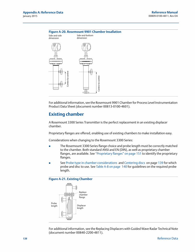
Reference Manual00809-0100-4811, Rev DA
Appendix A: Reference DataJanuary 2015
Figure A-20. Rosemount 9901 Chamber Insallation
For additional information, see the Rosemount 9901 Chamber for Process Level Instrumentation Product Data Sheet (document number 00813-0100-4601).
Existing chamber
A Rosemount 3300 Series Transmitter is the perfect replacement in an existing displacer chamber.
Proprietary flanges are offered, enabling use of existing chambers to make installation easy.
Considerations when changing to the Rosemount 3300 Series:
The Rosemount 3300 Series flange choice and probe length must be correctly matched to the chamber. Both standard ANSI and EN (DIN), as well as proprietary chamber flanges, are available. See “Proprietary flanges” on page 151 to identify the proprietary flanges.
See Probe type in chamber considerations and Centering discs on page 139 for which probe and disc to use. See Table A-8 on page 140 for guidelines on the required probe length.
Figure A-21. Existing Chamber
For additional information, see the Replacing Displacers with Guided Wave Radar Technical Note(document number 00840-2200-4811).
Side-and-side dimension
Side-and-bottom dimension
Cen
tre-
to-c
entr
e
Cen
tre-
to-c
entr
e
Replace chamberflange
Displacerlength
Probe length
138 Reference Data
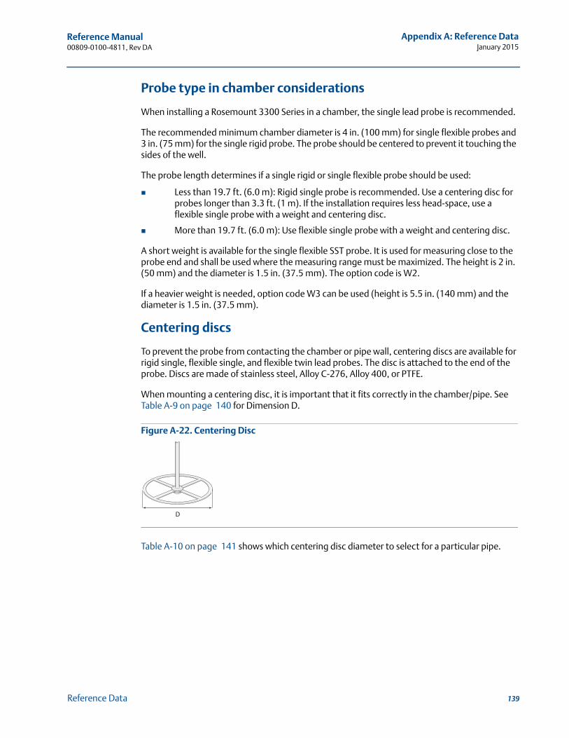
Reference Manual 00809-0100-4811, Rev DA
Appendix A: Reference DataJanuary 2015
Probe type in chamber considerations
When installing a Rosemount 3300 Series in a chamber, the single lead probe is recommended.
The recommended minimum chamber diameter is 4 in. (100 mm) for single flexible probes and 3 in. (75 mm) for the single rigid probe. The probe should be centered to prevent it touching the sides of the well.
The probe length determines if a single rigid or single flexible probe should be used:
Less than 19.7 ft. (6.0 m): Rigid single probe is recommended. Use a centering disc for probes longer than 3.3 ft. (1 m). If the installation requires less head-space, use a flexible single probe with a weight and centering disc.
More than 19.7 ft. (6.0 m): Use flexible single probe with a weight and centering disc.
A short weight is available for the single flexible SST probe. It is used for measuring close to the probe end and shall be used where the measuring range must be maximized. The height is 2 in. (50 mm) and the diameter is 1.5 in. (37.5 mm). The option code is W2.
If a heavier weight is needed, option code W3 can be used (height is 5.5 in. (140 mm) and the diameter is 1.5 in. (37.5 mm).
Centering discs
To prevent the probe from contacting the chamber or pipe wall, centering discs are available for rigid single, flexible single, and flexible twin lead probes. The disc is attached to the end of the probe. Discs are made of stainless steel, Alloy C-276, Alloy 400, or PTFE.
When mounting a centering disc, it is important that it fits correctly in the chamber/pipe. See Table A-9 on page 140 for Dimension D.
Figure A-22. Centering Disc
Table A-10 on page 141 shows which centering disc diameter to select for a particular pipe.
D
139Reference Data
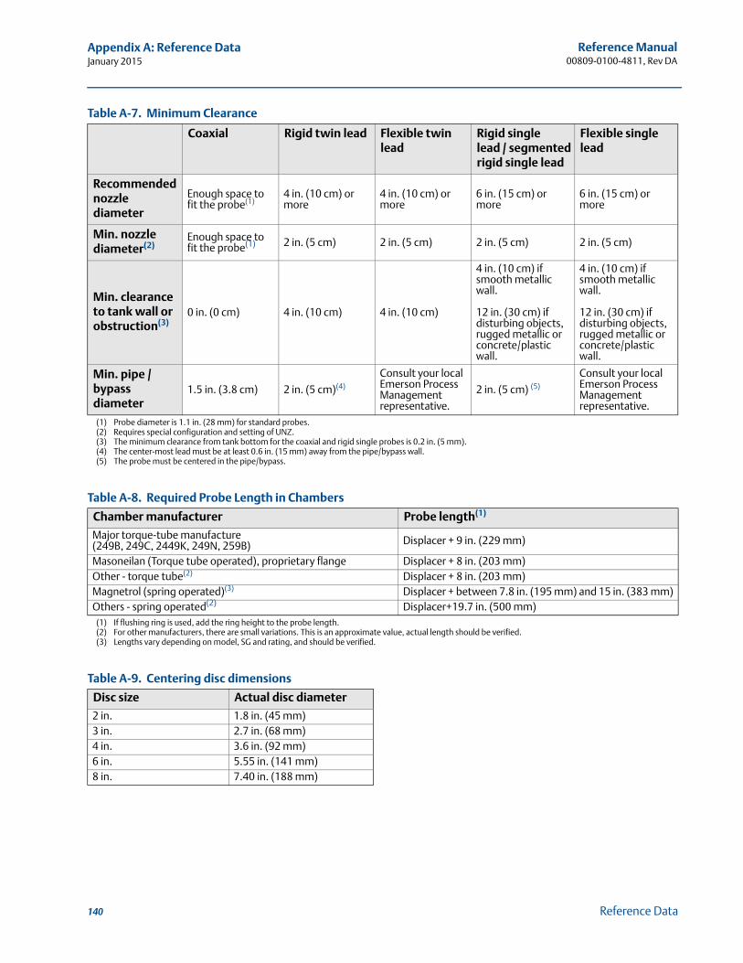
Reference Manual00809-0100-4811, Rev DA
Appendix A: Reference DataJanuary 2015
Table A-7. Minimum Clearance
Table A-8. Required Probe Length in Chambers
Table A-9. Centering disc dimensions
Coaxial Rigid twin lead Flexible twin lead
Rigid single lead / segmented rigid single lead
Flexible single lead
Recommended nozzle diameter
Enough space to fit the probe(1)
(1) Probe diameter is 1.1 in. (28 mm) for standard probes.
4 in. (10 cm) or more
4 in. (10 cm) or more
6 in. (15 cm) or more
6 in. (15 cm) or more
Min. nozzle diameter(2)
(2) Requires special configuration and setting of UNZ.
Enough space to fit the probe(1) 2 in. (5 cm) 2 in. (5 cm) 2 in. (5 cm) 2 in. (5 cm)
Min. clearance to tank wall or obstruction(3)
(3) The minimum clearance from tank bottom for the coaxial and rigid single probes is 0.2 in. (5 mm).
0 in. (0 cm) 4 in. (10 cm) 4 in. (10 cm)
4 in. (10 cm) if smooth metallic wall.
12 in. (30 cm) if disturbing objects, rugged metallic or concrete/plastic wall.
4 in. (10 cm) if smooth metallic wall.
12 in. (30 cm) if disturbing objects, rugged metallic or concrete/plastic wall.
Min. pipe / bypass diameter
1.5 in. (3.8 cm) 2 in. (5 cm)(4)
(4) The center-most lead must be at least 0.6 in. (15 mm) away from the pipe/bypass wall.
Consult your local Emerson Process Management representative.
2 in. (5 cm) (5)
(5) The probe must be centered in the pipe/bypass.
Consult your local Emerson Process Management representative.
Chamber manufacturer Probe length(1)
(1) If flushing ring is used, add the ring height to the probe length.
Major torque-tube manufacture (249B, 249C, 2449K, 249N, 259B) Displacer + 9 in. (229 mm)
Masoneilan (Torque tube operated), proprietary flange Displacer + 8 in. (203 mm)Other - torque tube(2)
(2) For other manufacturers, there are small variations. This is an approximate value, actual length should be verified.
Displacer + 8 in. (203 mm)Magnetrol (spring operated)(3)
(3) Lengths vary depending on model, SG and rating, and should be verified.
Displacer + between 7.8 in. (195 mm) and 15 in. (383 mm)Others - spring operated(2) Displacer+19.7 in. (500 mm)
Disc size Actual disc diameter
2 in. 1.8 in. (45 mm)3 in. 2.7 in. (68 mm)4 in. 3.6 in. (92 mm)6 in. 5.55 in. (141 mm)8 in. 7.40 in. (188 mm)
140 Reference Data
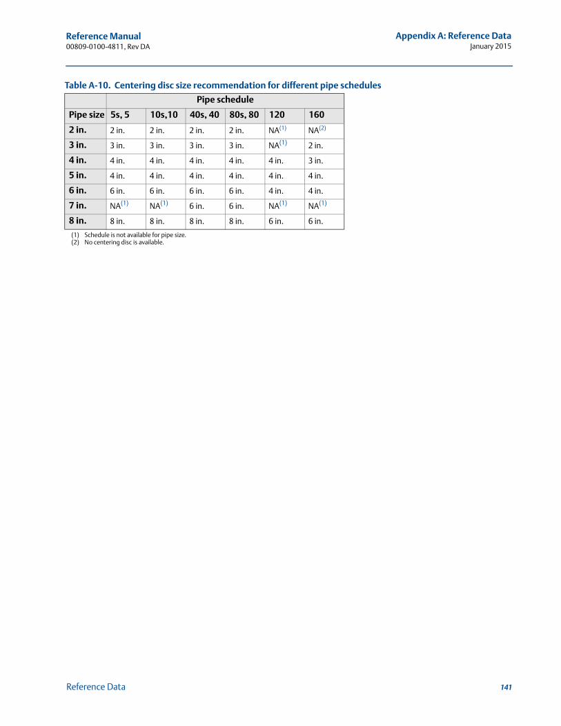
Reference Manual 00809-0100-4811, Rev DA
Appendix A: Reference DataJanuary 2015
Table A-10. Centering disc size recommendation for different pipe schedules
Pipe schedule
Pipe size 5s, 5 10s,10 40s, 40 80s, 80 120 160
2 in. 2 in. 2 in. 2 in. 2 in. NA(1)
(1) Schedule is not available for pipe size.
NA(2)
(2) No centering disc is available.
3 in. 3 in. 3 in. 3 in. 3 in. NA(1) 2 in.
4 in. 4 in. 4 in. 4 in. 4 in. 4 in. 3 in.
5 in. 4 in. 4 in. 4 in. 4 in. 4 in. 4 in.
6 in. 6 in. 6 in. 6 in. 6 in. 4 in. 4 in.
7 in. NA(1) NA(1) 6 in. 6 in. NA(1) NA(1)
8 in. 8 in. 8 in. 8 in. 8 in. 6 in. 6 in.
141Reference Data
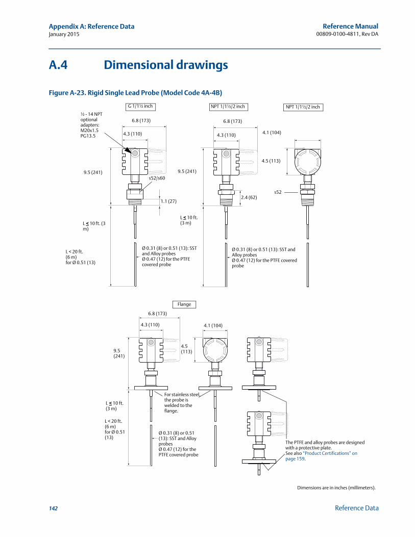
Reference Manual00809-0100-4811, Rev DA
Appendix A: Reference DataJanuary 2015
A.4 Dimensional drawings
Figure A-23. Rigid Single Lead Probe (Model Code 4A-4B)
G 1/1½ inch NPT 1/1½/2 inch NPT 1/1½/2 inch
½ - 14 NPToptional adapters:M20x1.5PG13.5
9.5 (241)
L< 10 ft. (3 m)
Ø 0.31 (8) or 0.51 (13): SST and Alloy probesØ 0.47 (12) for the PTFE covered probe
L < 20 ft. (6 m)for Ø 0.51 (13)
4.3 (110)
6.8 (173)
s52/s60
1.1 (27)
9.5 (241)
L < 10 ft. (3 m)
4.3 (110)
6.8 (173)
Ø 0.31 (8) or 0.51 (13): SST and Alloy probesØ 0.47 (12) for the PTFE covered probe
2.4 (62)s52
4.5 (113)
4.1 (104)
Flange
6.8 (173)
9.5 (241)
L< 10 ft. (3 m)
L < 20 ft. (6 m)for Ø 0.51 (13)
For stainless steel, the probe is welded to the flange.
Ø 0.31 (8) or 0.51 (13): SST and Alloy probesØ 0.47 (12) for the PTFE covered probe
4.1 (104)
4.5 (113)
The PTFE and alloy probes are designed with a protective plate.See also “Product Certifications” on page 159.
4.3 (110)
Dimensions are in inches (millimeters).
142 Reference Data
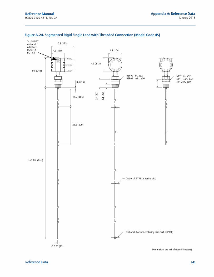
Reference Manual 00809-0100-4811, Rev DA
Appendix A: Reference DataJanuary 2015
Figure A-24. Segmented Rigid Single Lead with Threaded Connection (Model Code 4S)
½ - 14 NPToptional adapters:M20x1.5PG13.5
4.3 (110)
6.8 (173)
9.5 (241)
L < 20 ft. (6 m)
Ø 0.51 (13)
31.5 (800)
15.2 (385)
0.6 (15)
4.1 (104)
4.5 (113)
2.4
(62)
1.1
(27)
BSP-G 1 in., s52BSP-G 1½ in., s60
NPT 1 in., s52NPT 1½ in., s52NPT 2 in., s60
Dimensions are in inches (millimeters).
Optional: PTFE centering disc
Optional: Bottom centering disc (SST or PTFE)
143Reference Data
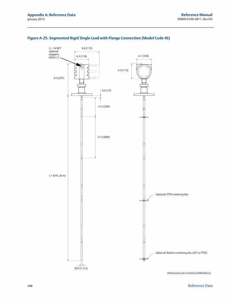
Reference Manual00809-0100-4811, Rev DA
Appendix A: Reference DataJanuary 2015
Figure A-25. Segmented Rigid Single Lead with Flange Connection (Model Code 4S)
½ - 14 NPToptional adapters:M20x1.5 4.3 (110)
6.8 (173)
9.5 (241)
L < 20 ft. (6 m)
31.5 (800)
15.2 (385)
0.6 (15)
4.1 (104)
4.5 (113)
Ø 0.51 (13)
Optional: PTFE centering disc
Optional: Bottom centering disc (SST or PTFE)
Dimensions are in inches (millimeters).
144 Reference Data
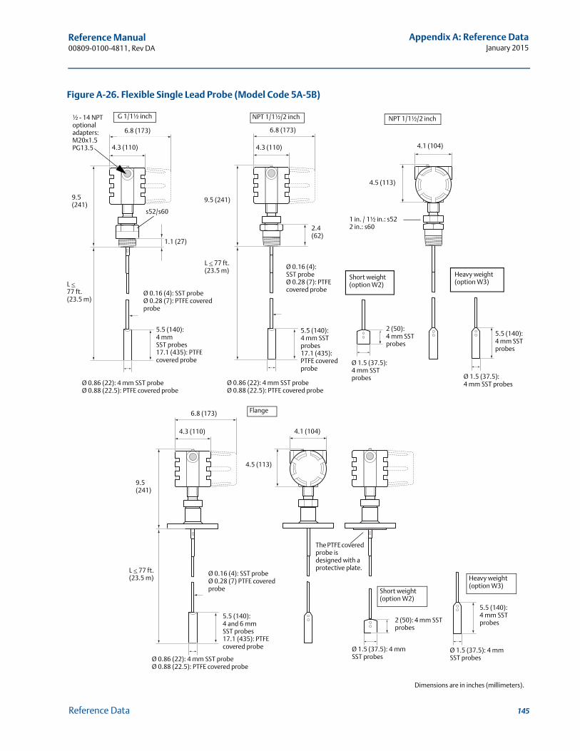
Reference Manual 00809-0100-4811, Rev DA
Appendix A: Reference DataJanuary 2015
Figure A-26. Flexible Single Lead Probe (Model Code 5A-5B)
½ - 14 NPToptional adapters:M20x1.5PG13.5
6.8 (173)
4.3 (110)
9.5 (241)
L 77 ft. (23.5 m)
s52/s60
1.1 (27)
5.5 (140): 4 mm SST probes17.1 (435): PTFE covered probe
Ø 0.86 (22): 4 mm SST probeØ 0.88 (22.5): PTFE covered probe
Ø 0.86 (22): 4 mm SST probeØ 0.88 (22.5): PTFE covered probe
5.5 (140): 4 mm SST probes17.1 (435): PTFE covered probe
Ø 0.16 (4): SST probeØ 0.28 (7): PTFE covered probe
9.5 (241)
L 77 ft. (23.5 m)
4.3 (110)
6.8 (173)
2.4 (62)
2 (50): 4 mm SST probes
Ø 1.5 (37.5): 4 mm SST probes
4.5 (113)
4.1 (104)
G 1/1½ inch NPT 1/1½/2 inch NPT 1/1½/2 inch
Ø 0.16 (4): SST probeØ 0.28 (7): PTFE covered probe
1 in. / 1½ in.: s522 in.: s60
Short weight (option W2)
Heavy weight (option W3)
Ø 1.5 (37.5): 4 mm SST probes
5.5 (140): 4 mm SST probes
6.8 (173)
9.5 (241)
L 77 ft. (23.5 m)
4.3 (110)
Ø 0.16 (4): SST probeØ 0.28 (7) PTFE covered probe
5.5 (140): 4 and 6 mm SST probes17.1 (435): PTFE covered probe
4.1 (104)
4.5 (113)
Flange
The PTFE covered probe is designed with a protective plate.
2 (50): 4 mm SST probes
Short weight (option W2)
Heavy weight (option W3)
5.5 (140):4 mm SST probes
Ø 0.86 (22): 4 mm SST probeØ 0.88 (22.5): PTFE covered probe
Ø 1.5 (37.5): 4 mm SST probes
Ø 1.5 (37.5): 4 mm SST probes
Dimensions are in inches (millimeters).
145Reference Data
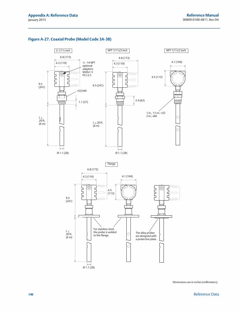
Reference Manual00809-0100-4811, Rev DA
Appendix A: Reference DataJanuary 2015
Figure A-27. Coaxial Probe (Model Code 3A-3B)
G 1/1½ inch NPT 1/1½/2 inch NPT 1/1½/2 inch
½ - 14 NPToptional adapters:M20x1.5PG13.5
9.5 (241)
L 20 ft.(6 m)
Ø 1.1 (28) Ø 1.1 (28)
s52/s60
1.1 (27)
4.3 (110)
6.8 (173)
9.5 (241)
L 20 ft.(6 m)
2.4 (62)
4.3 (110)
6.8 (173)
4.1 (104)
4.5 (113)
1 in., 1½ in.: s522 in.: s60
The alloy probes are designed with a protective plate.
6.8 (173)
4.3 (110)
9.5 (241)
L 20 ft.(6 m)
Ø 1.1 (28)
4.5 (113)
4.1 (104)
For stainless steel,the probe is welded to the flange.
Flange
Dimensions are in inches (millimeters).
146 Reference Data
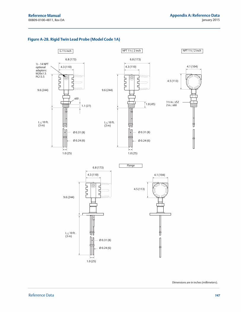
Reference Manual 00809-0100-4811, Rev DA
Appendix A: Reference DataJanuary 2015
Figure A-28. Rigid Twin Lead Probe (Model Code 1A)
4.1 (104)
s60
1.0 (25)
Ø 0.24 (6)
Ø 0.31 (8)
6.8 (173)
4.5 (113)
1½ in.: s522 in.: s60
L 10 ft. (3 m)
9.6 (244)
4.3 (110)
L 10 ft. (3 m)
Ø 0.31 (8)
Ø 0.24 (6)
1.0 (25)
4.3 (110)
6.8 (173)
½ - 14 NPToptional adapters:M20x1.5PG13.5
9.6 (244)
G 1½ inch NPT 1½ / 2 inch NPT 1½ / 2 inch
1.8 (45)1.1 (27)
1.0 (25)
4.3 (110)
6.8 (173)
9.6 (244)
Ø 0.31 (8)
Ø 0.24 (6)
4.1 (104)
4.5 (113)
L 10 ft .(3 m)
Flange
Dimensions are in inches (millimeters).
147Reference Data
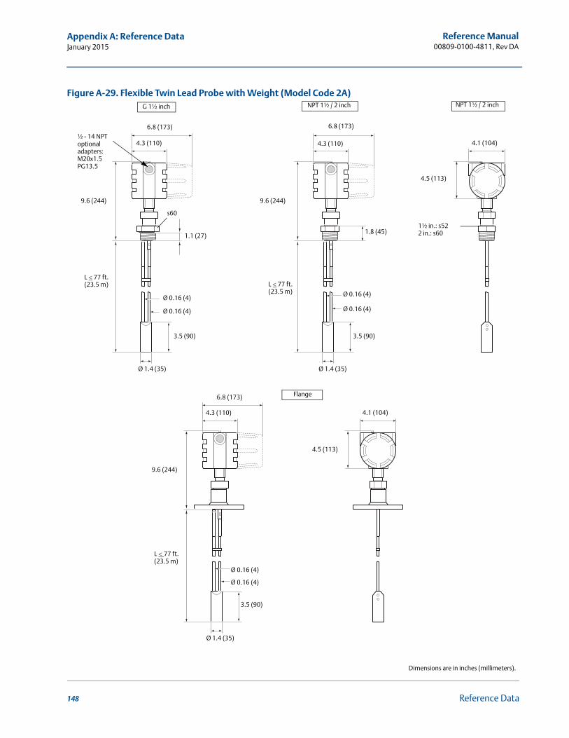
Reference Manual00809-0100-4811, Rev DA
Appendix A: Reference DataJanuary 2015
Figure A-29. Flexible Twin Lead Probe with Weight (Model Code 2A)
Ø 1.4 (35)
s60
3.5 (90) 3.5 (90)
Ø 0.16 (4)
Ø 0.16 (4)
Ø 1.4 (35)
4.1 (104)
4.5 (113)
1.8 (45)
L 77 ft. (23.5 m)
4.3 (110)
6.8 (173)
9.6 (244)
L 77 ft. (23.5 m)
4.3 (110)
6.8 (173)
Ø 0.16 (4)
Ø 0.16 (4)
½ - 14 NPToptional adapters:M20x1.5PG13.5
9.6 (244)
G 1½ inch NPT 1½ / 2 inch NPT 1½ / 2 inch
1½ in.: s522 in.: s601.1 (27)
4.3 (110)
6.8 (173)
3.5 (90)
Ø 1.4 (35)
4.1 (104)
4.5 (113)
Ø 0.16 (4)
Ø 0.16 (4)
9.6 (244)
L77 ft. (23.5 m)
Flange
Dimensions are in inches (millimeters).
148 Reference Data
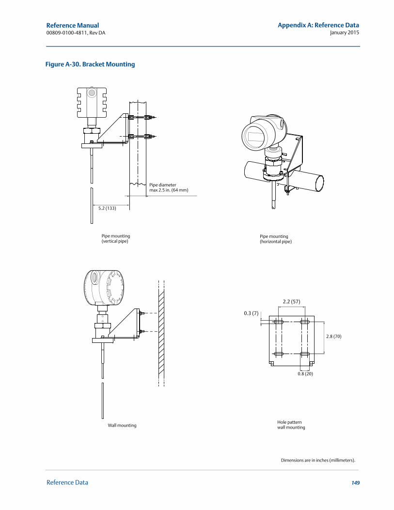
Reference Manual 00809-0100-4811, Rev DA
Appendix A: Reference DataJanuary 2015
Figure A-30. Bracket Mounting
Pipe mounting(vertical pipe)
Pipe mounting(horizontal pipe)
Wall mountingHole pattern wall mounting
5.2 (133)
Pipe diameter max 2.5 in. (64 mm)
Dimensions are in inches (millimeters).
2.2 (57)
0.3 (7)
2.8 (70)
0.8 (20)
149Reference Data
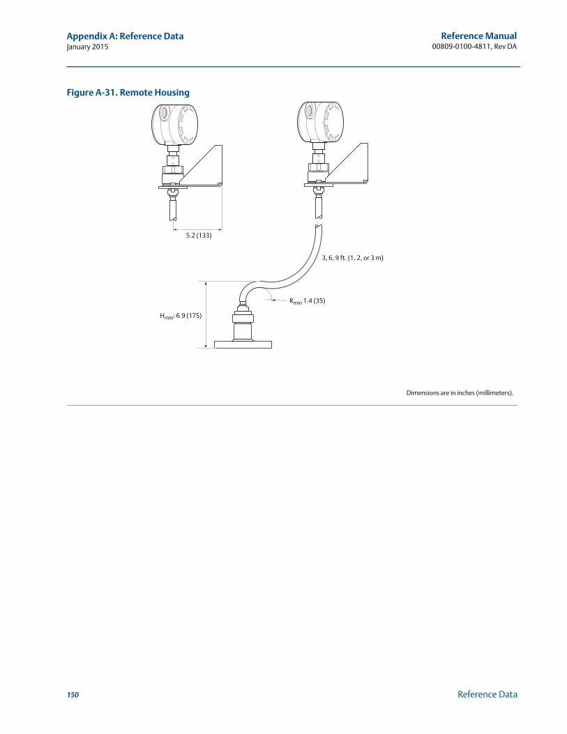
Reference Manual00809-0100-4811, Rev DA
Appendix A: Reference DataJanuary 2015
Figure A-31. Remote Housing
Dimensions are in inches (millimeters).
3, 6, 9 ft. (1, 2, or 3 m)
Hmin: 6.9 (175)
Rmin 1.4 (35)
5.2 (133)
150 Reference Data
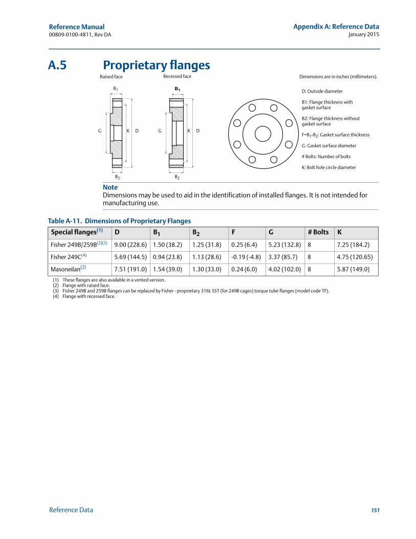
Reference Manual 00809-0100-4811, Rev DA
Appendix A: Reference DataJanuary 2015
A.5 Proprietary flanges
Table A-11. Dimensions of Proprietary Flanges
Special flanges(1)
(1) These flanges are also available in a vented version.
D B1 B2 F G # Bolts K
Fisher 249B/259B(2)(3)
(2) Flange with raised face.(3) Fisher 249B and 259B flanges can be replaced by Fisher - proprietary 316L SST (for 249B cages) torque tube flanges (model code TF).
9.00 (228.6) 1.50 (38.2) 1.25 (31.8) 0.25 (6.4) 5.23 (132.8) 8 7.25 (184.2)
Fisher 249C(4)
(4) Flange with recessed face.
5.69 (144.5) 0.94 (23.8) 1.13 (28.6) -0.19 (-4.8) 3.37 (85.7) 8 4.75 (120.65)
Masoneilan(2) 7.51 (191.0) 1.54 (39.0) 1.30 (33.0) 0.24 (6.0) 4.02 (102.0) 8 5.87 (149.0)
D
B1
G
Raised face Recessed face
K
D: Outside diameter
B1: Flange thickness withgasket surface
B2: Flange thickness withoutgasket surface
F=B1-B2: Gasket surface thickness
G: Gasket surface diameter
# Bolts: Number of bolts
K: Bolt hole circle diameter
NoteDimensions may be used to aid in the identification of installed flanges. It is not intended for manufacturing use.
G
B1
DK
B2 B2
Dimensions are in inches (millimeters).
151Reference Data
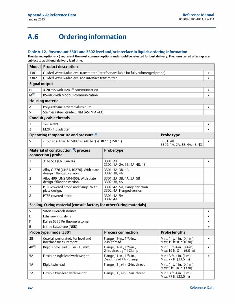
Reference Manual00809-0100-4811, Rev DA
Appendix A: Reference DataJanuary 2015
A.6 Ordering information
Table A-12. Rosemount 3301 and 3302 level and/or interface in liquids ordering informationThe starred options (★ ) represent the most common options and should be selected for best delivery. The non-starred offerings are subject to additional delivery lead time.
Model Product description
3301 Guided Wave Radar level transmitter (interface available for fully submerged probe) ★3302 Guided Wave Radar level and interface transmitter ★
Signal output
H 4-20 mA with HART® communication ★M(1) RS-485 with Modbus communication ★
Housing material
A Polyurethane-covered aluminum ★S Stainless steel, grade CF8M (ASTM A743)
Conduit / cable threads
1 ½–14 NPT ★2 M20 x 1.5 adapter ★
Operating temperature and pressure(2) Probe type
S - 15 psig (-1bar) to 580 psig (40 bar) @ 302 °F (150 °C) 3301: All3302: 1A, 2A, 3B, 4A, 4B, 4S
★
Material of construction(3): process connection / probe
Probe type
1 316L SST (EN 1.4404) 3301: All3302: 1A, 2A, 3B, 4A, 4B, 4S
★
2 Alloy C-276 (UNS N10276). With plate design if flanged version.
3301: 3A, 3B, 4A3302: 3B, 4A
3 Alloy 400 (UNS N04400). With plate design if flanged version.
3301: 3A, 3B, 4A, 5A, 5B3302: 3B, 4A
7 PTFE-covered probe and flange. With plate design.
3301: 4A, 5A, Flanged version3302: 4A, Flanged version
8 PTFE-covered probe 3301: 4A, 5A3302: 4A
Sealing, O-ring material (consult factory for other O-ring materials)
V Viton Fluoroelastomer ★E Ethylene Propylene ★K Kalrez 6375 Perfluoroelastomer ★B Nitrile Butadiene (NBR) ★
Probe type, model 3301 Process connection Probe lengths
3B Coaxial, perforated. For level and interface measurement.
Flange / 1-in., 11/2-in., 2-in. thread
Min.: 1 ft. 4 in. (0.4 m)Max: 19 ft. 8 in. (6 m)
★
4B(4) Rigid single lead 0.5 in. (13 mm) Flange / 1-in., 11/2-in., 2- in. thread / Tri-Clamp
Min.: 1 ft. 4 in. (0.4 m)Max: 19 ft. 8 in. (6.0 m)
★
5A Flexible single lead with weight Flange / 1-in., 11/2-in., 2-in. thread / Tri-Clamp
Min.: 3 ft. 4 in. (1 m)Max: 77 ft. (23.5 m)
★
1A Rigid twin lead Flange / 11/2-in., 2-in. thread Min.: 1 ft. 4 in. (0.4 m)Max: 9 ft. 10 in. (3 m)
2A Flexible twin lead with weight Flange / 11/2-in., 2-in. thread Min.: 3 ft. 4 in. (1 m)Max: 77 ft. (23.5 m)
152 Reference Data
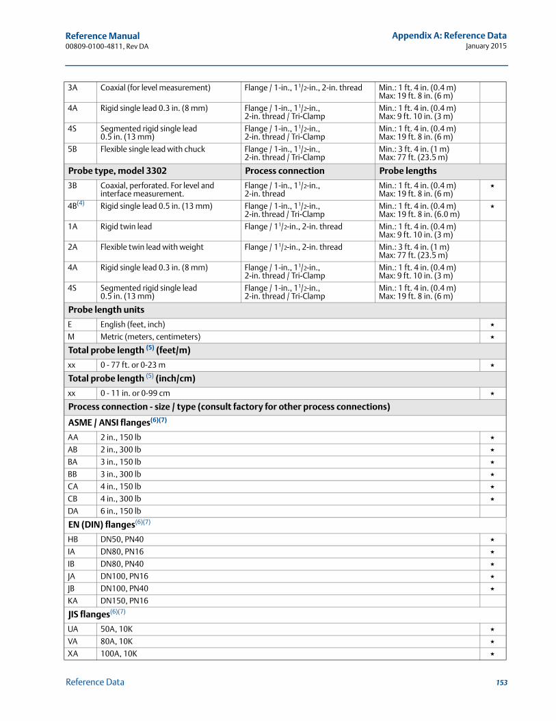
Reference Manual 00809-0100-4811, Rev DA
Appendix A: Reference DataJanuary 2015
3A Coaxial (for level measurement) Flange / 1-in., 11/2-in., 2-in. thread Min.: 1 ft. 4 in. (0.4 m)Max: 19 ft. 8 in. (6 m)
4A Rigid single lead 0.3 in. (8 mm) Flange / 1-in., 11/2-in., 2-in. thread / Tri-Clamp
Min.: 1 ft. 4 in. (0.4 m)Max: 9 ft. 10 in. (3 m)
4S Segmented rigid single lead 0.5 in. (13 mm)
Flange / 1-in., 11/2-in., 2-in. thread / Tri-Clamp
Min.: 1 ft. 4 in. (0.4 m)Max: 19 ft. 8 in. (6 m)
5B Flexible single lead with chuck Flange / 1-in., 11/2-in., 2-in. thread / Tri-Clamp
Min.: 3 ft. 4 in. (1 m)Max: 77 ft. (23.5 m)
Probe type, model 3302 Process connection Probe lengths
3B Coaxial, perforated. For level and interface measurement.
Flange / 1-in., 11/2-in., 2-in. thread
Min.: 1 ft. 4 in. (0.4 m)Max: 19 ft. 8 in. (6 m)
★
4B(4) Rigid single lead 0.5 in. (13 mm) Flange / 1-in., 11/2-in., 2-in. thread / Tri-Clamp
Min.: 1 ft. 4 in. (0.4 m)Max: 19 ft. 8 in. (6.0 m)
★
1A Rigid twin lead Flange / 11/2-in., 2-in. thread Min.: 1 ft. 4 in. (0.4 m)Max: 9 ft. 10 in. (3 m)
2A Flexible twin lead with weight Flange / 11/2-in., 2-in. thread Min.: 3 ft. 4 in. (1 m)Max: 77 ft. (23.5 m)
4A Rigid single lead 0.3 in. (8 mm) Flange / 1-in., 11/2-in., 2-in. thread / Tri-Clamp
Min.: 1 ft. 4 in. (0.4 m)Max: 9 ft. 10 in. (3 m)
4S Segmented rigid single lead 0.5 in. (13 mm)
Flange / 1-in., 11/2-in., 2-in. thread / Tri-Clamp
Min.: 1 ft. 4 in. (0.4 m)Max: 19 ft. 8 in. (6 m)
Probe length units
E English (feet, inch) ★M Metric (meters, centimeters) ★
Total probe length (5) (feet/m)
xx 0 - 77 ft. or 0-23 m ★
Total probe length (5) (inch/cm)
xx 0 - 11 in. or 0-99 cm ★
Process connection - size / type (consult factory for other process connections)
ASME / ANSI flanges(6)(7)
AA 2 in., 150 lb ★AB 2 in., 300 lb ★BA 3 in., 150 lb ★BB 3 in., 300 lb ★CA 4 in., 150 lb ★CB 4 in., 300 lb ★DA 6 in., 150 lb
EN (DIN) flanges(6)(7)
HB DN50, PN40 ★IA DN80, PN16 ★IB DN80, PN40 ★JA DN100, PN16 ★JB DN100, PN40 ★KA DN150, PN16
JIS flanges(6)(7)
UA 50A, 10K ★VA 80A, 10K ★XA 100A, 10K ★
153Reference Data
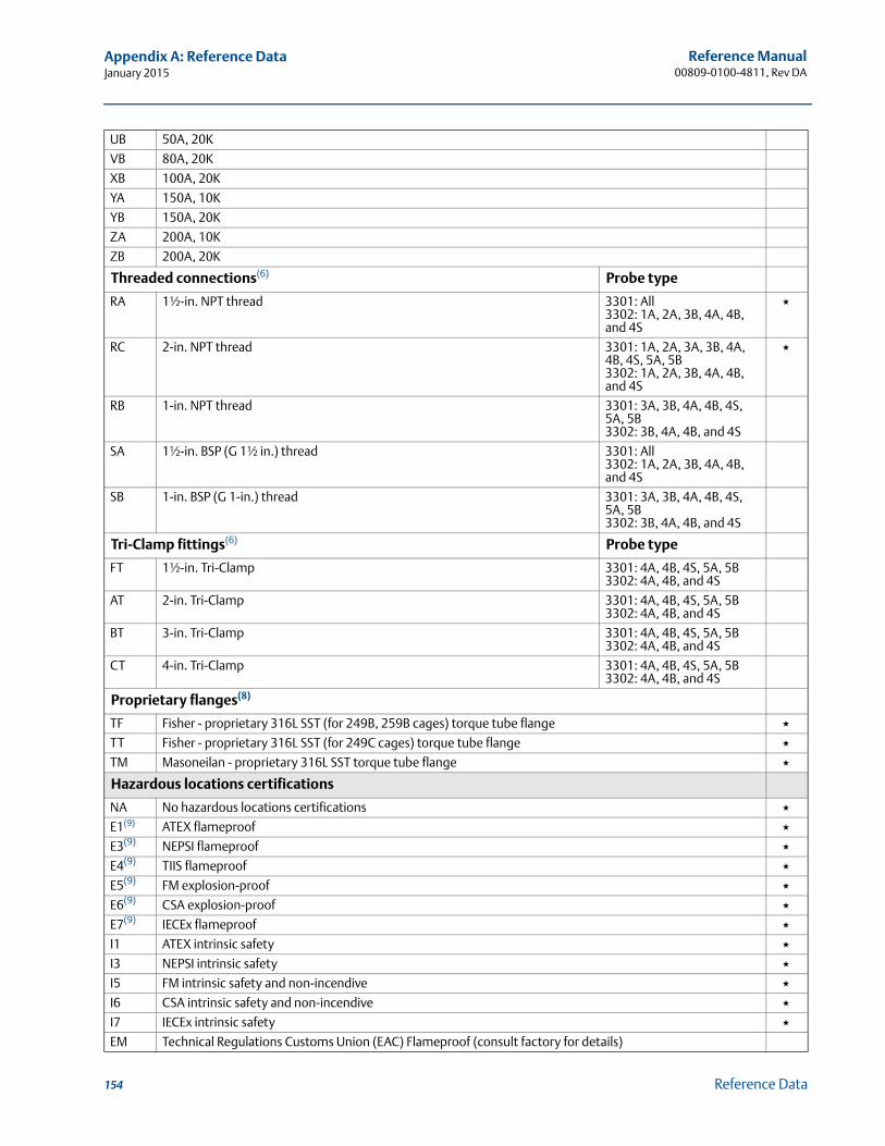
Reference Manual00809-0100-4811, Rev DA
Appendix A: Reference DataJanuary 2015
UB 50A, 20K
VB 80A, 20K
XB 100A, 20K
YA 150A, 10K
YB 150A, 20K
ZA 200A, 10K
ZB 200A, 20K
Threaded connections(6) Probe type
RA 1½-in. NPT thread 3301: All3302: 1A, 2A, 3B, 4A, 4B, and 4S
★
RC 2-in. NPT thread 3301: 1A, 2A, 3A, 3B, 4A, 4B, 4S, 5A, 5B3302: 1A, 2A, 3B, 4A, 4B, and 4S
★
RB 1-in. NPT thread 3301: 3A, 3B, 4A, 4B, 4S, 5A, 5B3302: 3B, 4A, 4B, and 4S
SA 1½-in. BSP (G 1½ in.) thread 3301: All3302: 1A, 2A, 3B, 4A, 4B, and 4S
SB 1-in. BSP (G 1-in.) thread 3301: 3A, 3B, 4A, 4B, 4S, 5A, 5B3302: 3B, 4A, 4B, and 4S
Tri-Clamp fittings(6) Probe type
FT 1½-in. Tri-Clamp 3301: 4A, 4B, 4S, 5A, 5B3302: 4A, 4B, and 4S
AT 2-in. Tri-Clamp 3301: 4A, 4B, 4S, 5A, 5B3302: 4A, 4B, and 4S
BT 3-in. Tri-Clamp 3301: 4A, 4B, 4S, 5A, 5B3302: 4A, 4B, and 4S
CT 4-in. Tri-Clamp 3301: 4A, 4B, 4S, 5A, 5B3302: 4A, 4B, and 4S
Proprietary flanges(8)
TF Fisher - proprietary 316L SST (for 249B, 259B cages) torque tube flange ★TT Fisher - proprietary 316L SST (for 249C cages) torque tube flange ★TM Masoneilan - proprietary 316L SST torque tube flange ★
Hazardous locations certifications
NA No hazardous locations certifications ★E1(9) ATEX flameproof ★E3(9) NEPSI flameproof ★E4(9) TIIS flameproof ★E5(9) FM explosion-proof ★E6(9) CSA explosion-proof ★E7(9) IECEx flameproof ★I1 ATEX intrinsic safety ★I3 NEPSI intrinsic safety ★I5 FM intrinsic safety and non-incendive ★I6 CSA intrinsic safety and non-incendive ★I7 IECEx intrinsic safety ★EM Technical Regulations Customs Union (EAC) Flameproof (consult factory for details)
154 Reference Data
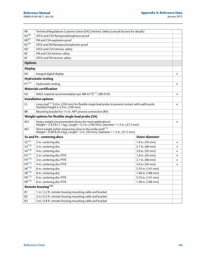
Reference Manual 00809-0100-4811, Rev DA
Appendix A: Reference DataJanuary 2015
IM Technical Regulations Customs Union (EAC) Intrinsic Safety (consult factory for details)
KA(9) ATEX and CSA flameproof/explosion-proof
KB(9) FM and CSA explosion-proof
KC(9) ATEX and FM flameproof/explosion-proof
KD ATEX and CSA intrinsic safety
KE FM and CSA intrinsic safety
KF ATEX and FM intrinsic safety
Options
Display
M1 Integral digital display ★
Hydrostatic testing
P1(10) Hydrostatic testing ★
Materials certification
N2 NACE material recommendation per MR-0175(11), MR-0103 ★
Installation options
LS Long stud(12) 9.8 in. (250 mm) for flexible single lead probe to prevent contact with wall/nozzle.Standard height is 3.9 in. (100 mm).
★
BR Mounting bracket for 1½-in. NPT process connection (RA)
Weight options for flexible single lead probe (5A)
W3 Heavy weight (recommended choice for most applications) Weight = 2.43 lb (1.1 kg), Length = 5.5 in. (140 mm), Diameter = 1.5 in. (37.5 mm)
★
W2 Short weight (when measuring close to the probe end)(13)
Weight = 0.88 lb (0.4 kg), Length = 2 in. (50 mm), Diameter = 1.5 in. (37.5 mm)
Sx and Px - centering discs Outer diameter
S2(14) 2-in. centering disc 1.8 in. (45 mm) ★S3(14) 3-in. centering disc 2.7 in. (68 mm) ★S4(14) 4-in. centering disc 3.6 in. (92 mm) ★P2(15) 2-in. centering disc PTFE 1.8 in. (45 mm) ★P3(15) 3-in. centering disc PTFE 2.7 in. (68 mm) ★P4(15) 4-in. centering disc PTFE 3.6 in. (92 mm) ★S6(14) 6-in. centering disc 5.55 in. (141 mm)
S8(14) 8-in. centering disc 7.40 in. (188 mm)
P6(15) 6-in. centering disc PTFE 5.55 in. (141 mm)
P8(15) 8-in. centering disc PTFE 7.40 in. (188 mm)
Remote housing(16)
B1 1 m / 3.2 ft. remote housing mounting cable and bracket
B2 2 m / 6.5 ft. remote housing mounting cable and bracket
B3 3 m / 9.8 ft. remote housing mounting cable and bracket
155Reference Data
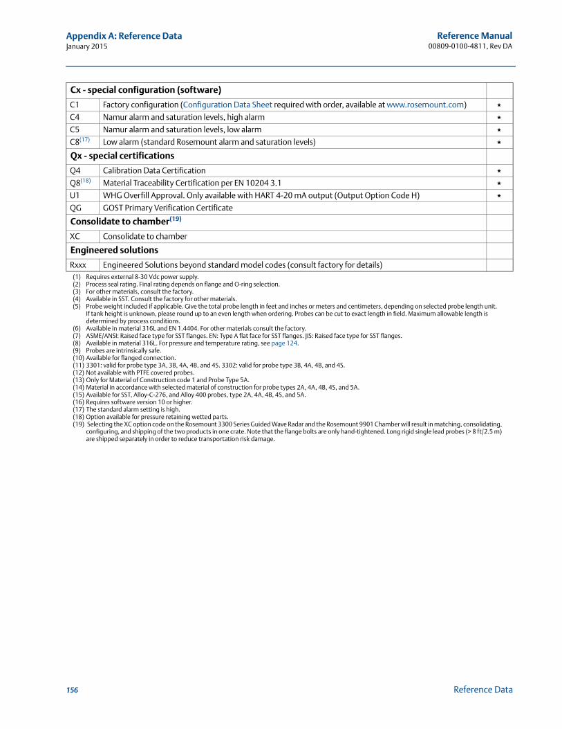
Reference Manual00809-0100-4811, Rev DA
Appendix A: Reference DataJanuary 2015
Cx - special configuration (software)
C1 Factory configuration (Configuration Data Sheet required with order, available at www.rosemount.com) ★C4 Namur alarm and saturation levels, high alarm ★C5 Namur alarm and saturation levels, low alarm ★C8(17) Low alarm (standard Rosemount alarm and saturation levels) ★
Qx - special certifications
Q4 Calibration Data Certification ★Q8(18) Material Traceability Certification per EN 10204 3.1 ★U1 WHG Overfill Approval. Only available with HART 4-20 mA output (Output Option Code H) ★QG GOST Primary Verification Certificate
Consolidate to chamber(19)
XC Consolidate to chamber
Engineered solutions
Rxxx Engineered Solutions beyond standard model codes (consult factory for details)(1) Requires external 8-30 Vdc power supply.(2) Process seal rating. Final rating depends on flange and O-ring selection.(3) For other materials, consult the factory.(4) Available in SST. Consult the factory for other materials.(5) Probe weight included if applicable. Give the total probe length in feet and inches or meters and centimeters, depending on selected probe length unit.
If tank height is unknown, please round up to an even length when ordering. Probes can be cut to exact length in field. Maximum allowable length is determined by process conditions.
(6) Available in material 316L and EN 1.4404. For other materials consult the factory. (7) ASME/ANSI: Raised face type for SST flanges. EN: Type A flat face for SST flanges. JIS: Raised face type for SST flanges.(8) Available in material 316L. For pressure and temperature rating, see page 124.(9) Probes are intrinsically safe.(10) Available for flanged connection.(11) 3301: valid for probe type 3A, 3B, 4A, 4B, and 4S. 3302: valid for probe type 3B, 4A, 4B, and 4S.(12) Not available with PTFE covered probes.(13) Only for Material of Construction code 1 and Probe Type 5A.(14) Material in accordance with selected material of construction for probe types 2A, 4A, 4B, 4S, and 5A. (15) Available for SST, Alloy-C-276, and Alloy 400 probes, type 2A, 4A, 4B, 4S, and 5A.(16) Requires software version 10 or higher.(17) The standard alarm setting is high.(18) Option available for pressure retaining wetted parts.(19) Selecting the XC option code on the Rosemount 3300 Series Guided Wave Radar and the Rosemount 9901 Chamber will result in matching, consolidating,
configuring, and shipping of the two products in one crate. Note that the flange bolts are only hand-tightened. Long rigid single lead probes (> 8 ft/2.5 m) are shipped separately in order to reduce transportation risk damage.
156 Reference Data
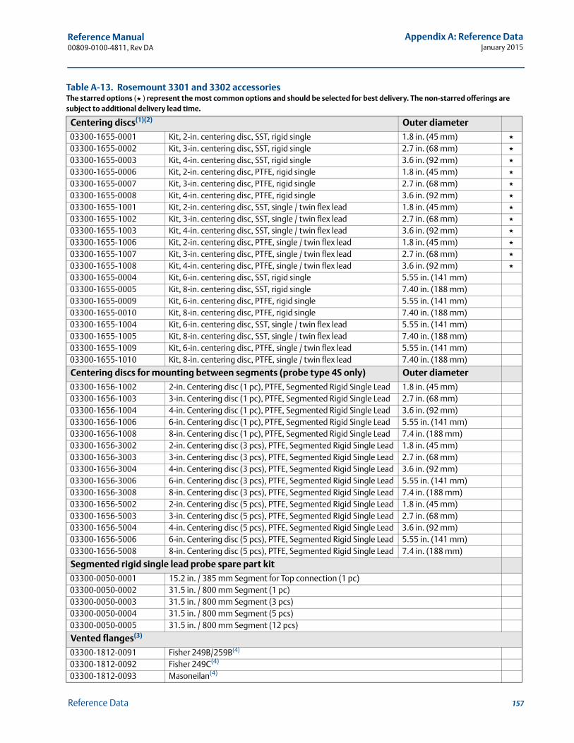
Reference Manual 00809-0100-4811, Rev DA
Appendix A: Reference DataJanuary 2015
Table A-13. Rosemount 3301 and 3302 accessoriesThe starred options (★ ) represent the most common options and should be selected for best delivery. The non-starred offerings are subject to additional delivery lead time.
Centering discs(1)(2) Outer diameter
03300-1655-0001 Kit, 2-in. centering disc, SST, rigid single 1.8 in. (45 mm) ★03300-1655-0002 Kit, 3-in. centering disc, SST, rigid single 2.7 in. (68 mm) ★03300-1655-0003 Kit, 4-in. centering disc, SST, rigid single 3.6 in. (92 mm) ★03300-1655-0006 Kit, 2-in. centering disc, PTFE, rigid single 1.8 in. (45 mm) ★03300-1655-0007 Kit, 3-in. centering disc, PTFE, rigid single 2.7 in. (68 mm) ★03300-1655-0008 Kit, 4-in. centering disc, PTFE, rigid single 3.6 in. (92 mm) ★03300-1655-1001 Kit, 2-in. centering disc, SST, single / twin flex lead 1.8 in. (45 mm) ★03300-1655-1002 Kit, 3-in. centering disc, SST, single / twin flex lead 2.7 in. (68 mm) ★03300-1655-1003 Kit, 4-in. centering disc, SST, single / twin flex lead 3.6 in. (92 mm) ★03300-1655-1006 Kit, 2-in. centering disc, PTFE, single / twin flex lead 1.8 in. (45 mm) ★03300-1655-1007 Kit, 3-in. centering disc, PTFE, single / twin flex lead 2.7 in. (68 mm) ★03300-1655-1008 Kit, 4-in. centering disc, PTFE, single / twin flex lead 3.6 in. (92 mm) ★03300-1655-0004 Kit, 6-in. centering disc, SST, rigid single 5.55 in. (141 mm)03300-1655-0005 Kit, 8-in. centering disc, SST, rigid single 7.40 in. (188 mm)03300-1655-0009 Kit, 6-in. centering disc, PTFE, rigid single 5.55 in. (141 mm)03300-1655-0010 Kit, 8-in. centering disc, PTFE, rigid single 7.40 in. (188 mm)03300-1655-1004 Kit, 6-in. centering disc, SST, single / twin flex lead 5.55 in. (141 mm)03300-1655-1005 Kit, 8-in. centering disc, SST, single / twin flex lead 7.40 in. (188 mm)03300-1655-1009 Kit, 6-in. centering disc, PTFE, single / twin flex lead 5.55 in. (141 mm)03300-1655-1010 Kit, 8-in. centering disc, PTFE, single / twin flex lead 7.40 in. (188 mm)
Centering discs for mounting between segments (probe type 4S only) Outer diameter
03300-1656-1002 2-in. Centering disc (1 pc), PTFE, Segmented Rigid Single Lead 1.8 in. (45 mm)03300-1656-1003 3-in. Centering disc (1 pc), PTFE, Segmented Rigid Single Lead 2.7 in. (68 mm)03300-1656-1004 4-in. Centering disc (1 pc), PTFE, Segmented Rigid Single Lead 3.6 in. (92 mm)03300-1656-1006 6-in. Centering disc (1 pc), PTFE, Segmented Rigid Single Lead 5.55 in. (141 mm)03300-1656-1008 8-in. Centering disc (1 pc), PTFE, Segmented Rigid Single Lead 7.4 in. (188 mm)03300-1656-3002 2-in. Centering disc (3 pcs), PTFE, Segmented Rigid Single Lead 1.8 in. (45 mm)03300-1656-3003 3-in. Centering disc (3 pcs), PTFE, Segmented Rigid Single Lead 2.7 in. (68 mm)03300-1656-3004 4-in. Centering disc (3 pcs), PTFE, Segmented Rigid Single Lead 3.6 in. (92 mm)03300-1656-3006 6-in. Centering disc (3 pcs), PTFE, Segmented Rigid Single Lead 5.55 in. (141 mm)03300-1656-3008 8-in. Centering disc (3 pcs), PTFE, Segmented Rigid Single Lead 7.4 in. (188 mm)03300-1656-5002 2-in. Centering disc (5 pcs), PTFE, Segmented Rigid Single Lead 1.8 in. (45 mm)03300-1656-5003 3-in. Centering disc (5 pcs), PTFE, Segmented Rigid Single Lead 2.7 in. (68 mm)03300-1656-5004 4-in. Centering disc (5 pcs), PTFE, Segmented Rigid Single Lead 3.6 in. (92 mm)03300-1656-5006 6-in. Centering disc (5 pcs), PTFE, Segmented Rigid Single Lead 5.55 in. (141 mm)03300-1656-5008 8-in. Centering disc (5 pcs), PTFE, Segmented Rigid Single Lead 7.4 in. (188 mm)
Segmented rigid single lead probe spare part kit
03300-0050-0001 15.2 in. / 385 mm Segment for Top connection (1 pc)03300-0050-0002 31.5 in. / 800 mm Segment (1 pc)03300-0050-0003 31.5 in. / 800 mm Segment (3 pcs)03300-0050-0004 31.5 in. / 800 mm Segment (5 pcs)03300-0050-0005 31.5 in. / 800 mm Segment (12 pcs)
Vented flanges(3)
03300-1812-0091 Fisher 249B/259B(4)
03300-1812-0092 Fisher 249C(4)
03300-1812-0093 Masoneilan(4)
157Reference Data

Reference Manual00809-0100-4811, Rev DA
Appendix A: Reference DataJanuary 2015
HART modem and cables
03300-7004-0001 MACTek Viator HART modem and cables (RS232 connection) ★03300-7004-0002 MACTek Viator HART modem and cables (USB connection) ★
(1) If a centering disc is required for a flanged probe, the centering disc can be ordered with options Sx or Px, see page 155. If a centering disc is required for a threaded connection or as a spare part, it should be ordered using the item numbers listed below.
(2) To order a centering disc in a different material, consult the factory.(3) 1½-in. NPT threaded connection (RA) is required.(4) For pressure and temperature rating, see “Fisher & Masoneilan flange rating” on page 124.
158 Reference Data
Reference Manual 00809-0100-4570, Rev AC
Appendix B: Product CertificationsJanuary 2015
Appendix B Product Certifications
Safety messages . . . . . . . . . . . . . . . . . . . . . . . . . . . . . . . . . . . . . . . . . . . . . . . . . . . . . . . . . . . . page 159EU Conformity . . . . . . . . . . . . . . . . . . . . . . . . . . . . . . . . . . . . . . . . . . . . . . . . . . . . . . . . . . . . . . page 160Hazardous locations certifications . . . . . . . . . . . . . . . . . . . . . . . . . . . . . . . . . . . . . . . . . . . . page 161Other certifications . . . . . . . . . . . . . . . . . . . . . . . . . . . . . . . . . . . . . . . . . . . . . . . . . . . . . . . . . page 172Approval drawings . . . . . . . . . . . . . . . . . . . . . . . . . . . . . . . . . . . . . . . . . . . . . . . . . . . . . . . . . . page 172
B.1 Safety messages
Procedures and instructions in this section may require special precautions to ensure the safety of the personnel performing the operations. Information that raises potential safety issues is
indicated by a warning symbol ( ). Please refer to the following safety messages before performing an operation preceded by this symbol.
Explosions could result in death or serious injury.
Verify that the operating environment of the gauge is consistent with the appropriate hazardous locations certifications.
Before connecting a HART®-based communicator in an explosive atmosphere, make sure the instruments in the loop are installed in accordance with intrinsically safe or non-incendive field wiring practices.
In an explosion-proof/flameproof installation, do not remove the transmitter cover when power is applied to the unit.
Failure to follow safe installation and servicing guidelines could result in death or serious injury.
Make sure the transmitter is installed by qualified personnel and in accordance with applicable code of practice.
Use the equipment only as specified in this manual. Failure to do so may impair the protection provided by the equipment.
Do not perform any service other than those contained in this manual unless you are qualified.
A safety isolator such as a zener barrier is always needed for intrinsic safety.
159Product Certifications

Reference Manual00809-0100-4570, Rev AC
Appendix B: Product CertificationsJanuary 2015
B.2 EU Conformity
The most recent revision of the EC declaration of conformity can be found at www.rosemount.com.
High voltage that may be present on leads could cause electrical shock.
Avoid contact with leads and terminals. Make sure the main power to the radar transmitter is off and the lines to any other
external power source are disconnected or not powered while wiring the transmitter. Probes covered with plastic and/or with plastic discs may generate an ignition-capable
level of electrostatic charge under certain extreme conditions. Therefore, when the probe is used in a potentially explosive atmosphere, appropriate measures must be taken to prevent electrostatic discharge.
Eliminate the risk of ESD discharge prior to dismounting the transmitter head. Probes may generate an ignition- capable level of electrostatic charge under extreme
conditions. During any type of installation or maintenance in a potentially explosive atmosphere, the responsible person should make sure that any ESD risks are eliminated before attempting to separate the probe from the transmitter head.
160 Product Certifications
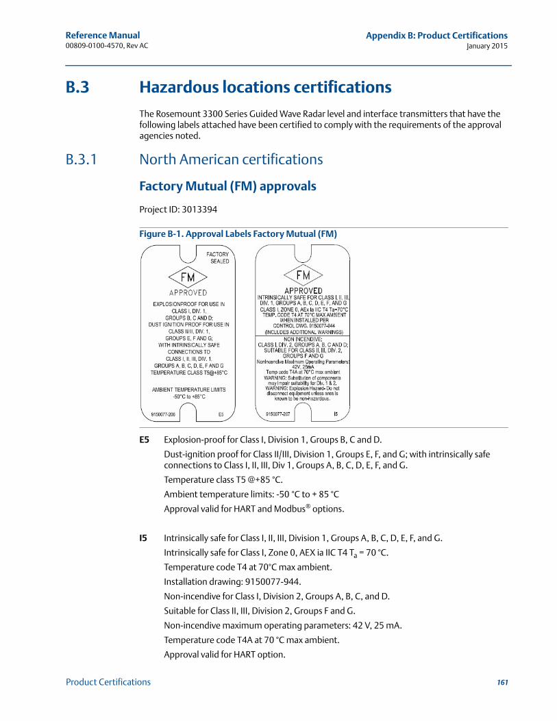
Reference Manual 00809-0100-4570, Rev AC
Appendix B: Product CertificationsJanuary 2015
B.3 Hazardous locations certifications
The Rosemount 3300 Series Guided Wave Radar level and interface transmitters that have the following labels attached have been certified to comply with the requirements of the approval agencies noted.
B.3.1 North American certifications
Factory Mutual (FM) approvals
Project ID: 3013394
Figure B-1. Approval Labels Factory Mutual (FM)
E5 Explosion-proof for Class I, Division 1, Groups B, C and D.
Dust-ignition proof for Class II/III, Division 1, Groups E, F, and G; with intrinsically safe connections to Class I, II, III, Div 1, Groups A, B, C, D, E, F, and G.
Temperature class T5 @+85 °C.
Ambient temperature limits: -50 °C to + 85 °C
Approval valid for HART and Modbus® options.
I5 Intrinsically safe for Class I, II, III, Division 1, Groups A, B, C, D, E, F, and G.
Intrinsically safe for Class I, Zone 0, AEX ia IIC T4 Ta = 70 °C.
Temperature code T4 at 70°C max ambient.
Installation drawing: 9150077-944.
Non-incendive for Class I, Division 2, Groups A, B, C, and D.
Suitable for Class II, III, Division 2, Groups F and G.
Non-incendive maximum operating parameters: 42 V, 25 mA.
Temperature code T4A at 70 °C max ambient.
Approval valid for HART option.
161Product Certifications
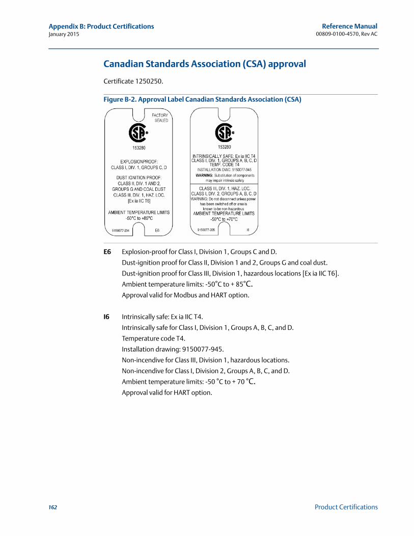
Reference Manual00809-0100-4570, Rev AC
Appendix B: Product CertificationsJanuary 2015
Canadian Standards Association (CSA) approval
Certificate 1250250.
Figure B-2. Approval Label Canadian Standards Association (CSA)
E6 Explosion-proof for Class I, Division 1, Groups C and D.
Dust-ignition proof for Class II, Division 1 and 2, Groups G and coal dust.
Dust-ignition proof for Class III, Division 1, hazardous locations [Ex ia IIC T6].
Ambient temperature limits: -50°C to + 85°C.Approval valid for Modbus and HART option.
I6 Intrinsically safe: Ex ia IIC T4.
Intrinsically safe for Class I, Division 1, Groups A, B, C, and D.
Temperature code T4.
Installation drawing: 9150077-945.
Non-incendive for Class III, Division 1, hazardous locations.
Non-incendive for Class I, Division 2, Groups A, B, C, and D.
Ambient temperature limits: -50 °C to + 70 °C.Approval valid for HART option.
162 Product Certifications
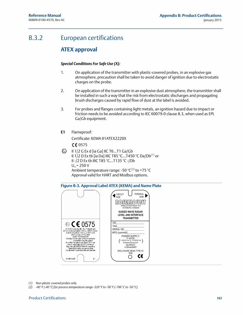
Reference Manual 00809-0100-4570, Rev AC
Appendix B: Product CertificationsJanuary 2015
B.3.2 European certifications
ATEX approval
Special Conditions For Safe Use (X):
1. On application of the transmitter with plastic-covered probes, in an explosive gas atmosphere, precaution shall be taken to avoid danger of ignition due to electrostatic charges on the probe.
2. On application of the transmitter in an explosive dust atmosphere, the transmitter shall be installed in such a way that the risk from electrostatic discharges and propagating brush discharges caused by rapid flow of dust at the label is avoided.
3. For probes and flanges containing light metals, an ignition hazard due to impact or friction needs to be avoided according to IEC 60079-0 clause 8.3, when used as EPL Ga/Gb equipment.
E1 Flameproof:
Certificate: KEMA 01ATEX2220X
0575
II 1/2 G Ex d [ia Ga] IIC T6...T1 Ga/GbII 1/2 D Ex tb [ia Da] IIIC T85 °C...T450 °C Da/Db(1) orII -/2 D Ex tb IIIC T85 °C...T135 °C -/Db Um = 250 VAmbient temperature range: -50 °C(2) to +75 °CApproval valid for HART and Modbus options.
Figure B-3. Approval Label ATEX (KEMA) and Name Plate
(1) Non-plastic covered probes only.(2) -40 °F (-40 °C) for process temperature range -320 °F to -58 °F (-196 °C to -50 °C).
163Product Certifications
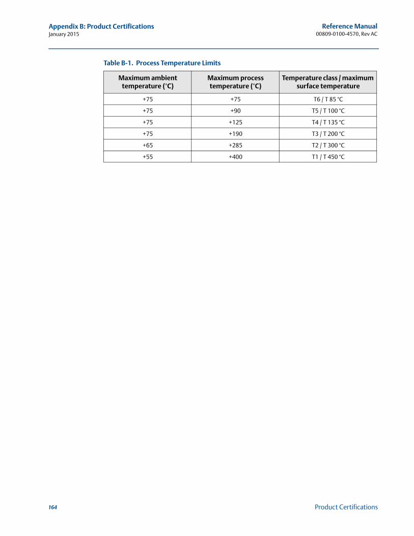
Reference Manual00809-0100-4570, Rev AC
Appendix B: Product CertificationsJanuary 2015
Table B-1. Process Temperature Limits
Maximum ambient temperature (°C)
Maximum process temperature (°C)
Temperature class / maximum surface temperature
+75 +75 T6 / T 85 °C
+75 +90 T5 / T 100 °C
+75 +125 T4 / T 135 °C
+75 +190 T3 / T 200 °C
+65 +285 T2 / T 300 °C
+55 +400 T1 / T 450 °C
164 Product Certifications
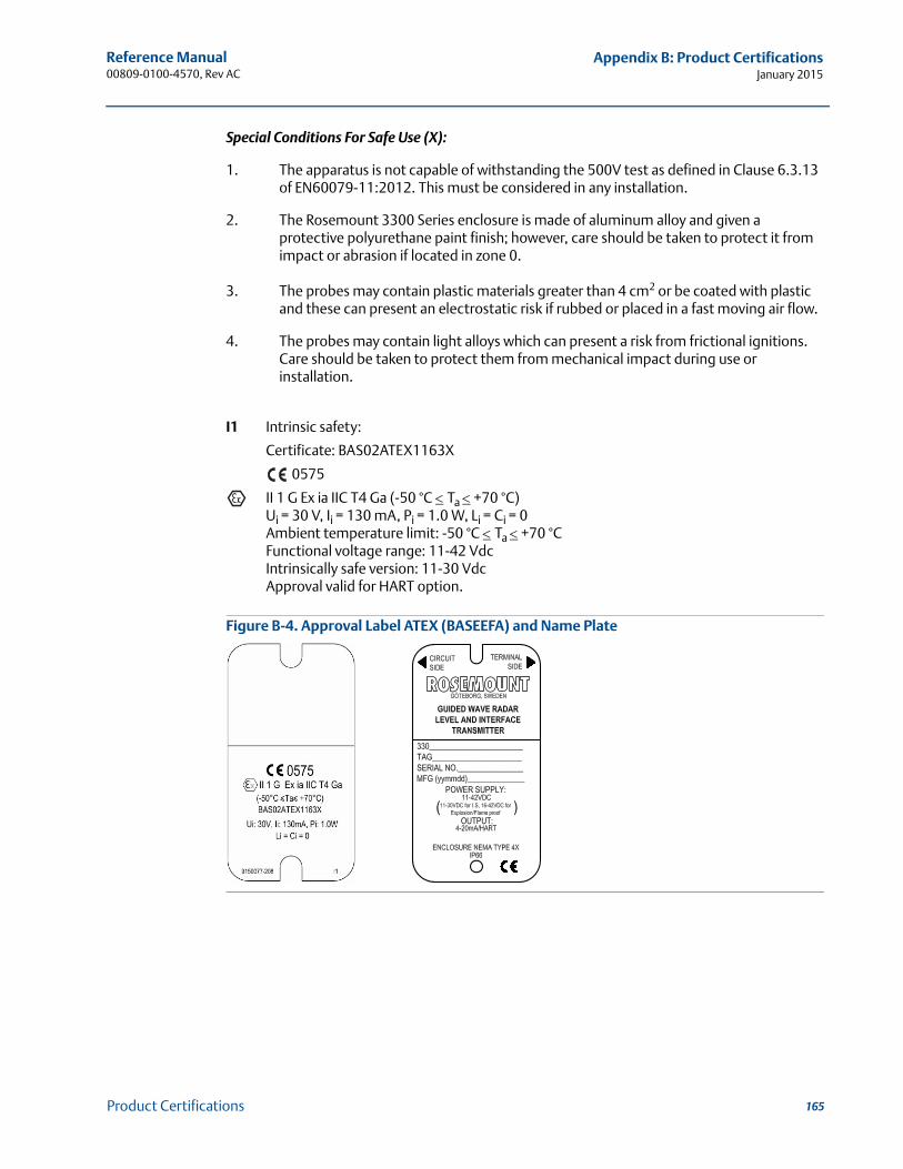
Reference Manual 00809-0100-4570, Rev AC
Appendix B: Product CertificationsJanuary 2015
Special Conditions For Safe Use (X):
1. The apparatus is not capable of withstanding the 500V test as defined in Clause 6.3.13 of EN60079-11:2012. This must be considered in any installation.
2. The Rosemount 3300 Series enclosure is made of aluminum alloy and given a protective polyurethane paint finish; however, care should be taken to protect it from impact or abrasion if located in zone 0.
3. The probes may contain plastic materials greater than 4 cm2 or be coated with plastic and these can present an electrostatic risk if rubbed or placed in a fast moving air flow.
4. The probes may contain light alloys which can present a risk from frictional ignitions. Care should be taken to protect them from mechanical impact during use or installation.
I1 Intrinsic safety:
Certificate: BAS02ATEX1163X
0575
II 1 G Ex ia IIC T4 Ga (-50 °C Ta +70 °C)Ui = 30 V, Ii = 130 mA, Pi = 1.0 W, Li = Ci = 0Ambient temperature limit: -50 °C Ta +70 °CFunctional voltage range: 11-42 VdcIntrinsically safe version: 11-30 VdcApproval valid for HART option.
Figure B-4. Approval Label ATEX (BASEEFA) and Name Plate
165Product Certifications
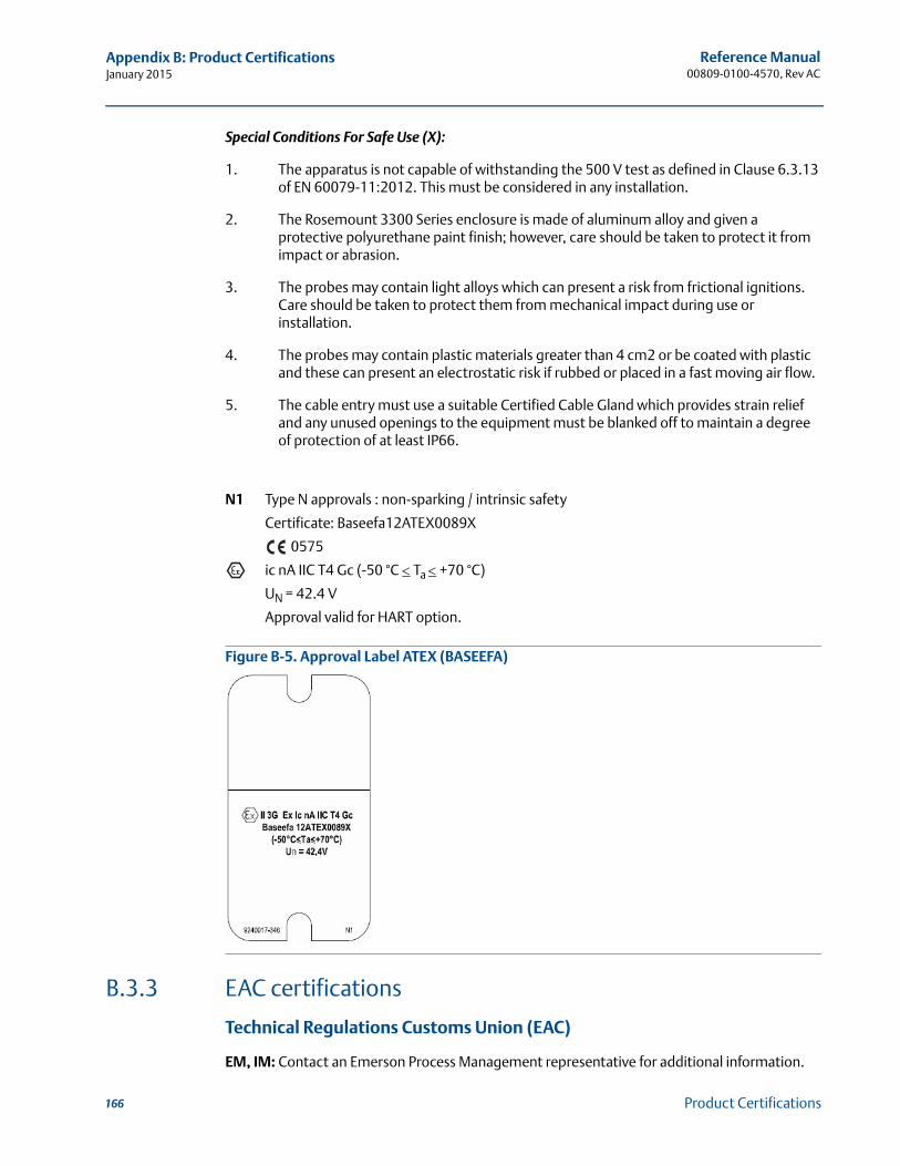
Reference Manual00809-0100-4570, Rev AC
Appendix B: Product CertificationsJanuary 2015
Special Conditions For Safe Use (X):
1. The apparatus is not capable of withstanding the 500 V test as defined in Clause 6.3.13 of EN 60079-11:2012. This must be considered in any installation.
2. The Rosemount 3300 Series enclosure is made of aluminum alloy and given a protective polyurethane paint finish; however, care should be taken to protect it from impact or abrasion.
3. The probes may contain light alloys which can present a risk from frictional ignitions. Care should be taken to protect them from mechanical impact during use or installation.
4. The probes may contain plastic materials greater than 4 cm2 or be coated with plastic and these can present an electrostatic risk if rubbed or placed in a fast moving air flow.
5. The cable entry must use a suitable Certified Cable Gland which provides strain relief and any unused openings to the equipment must be blanked off to maintain a degree of protection of at least IP66.
N1 Type N approvals : non-sparking / intrinsic safety
Certificate: Baseefa12ATEX0089X
0575
ic nA IIC T4 Gc (-50 °C Ta +70 °C)
UN = 42.4 V
Approval valid for HART option.
Figure B-5. Approval Label ATEX (BASEEFA)
B.3.3 EAC certifications
Technical Regulations Customs Union (EAC)
EM, IM: Contact an Emerson Process Management representative for additional information.
166 Product Certifications
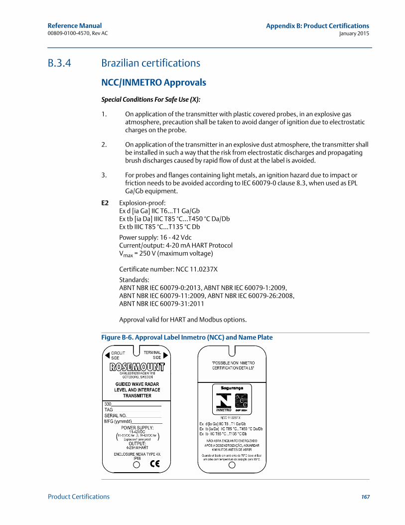
Reference Manual 00809-0100-4570, Rev AC
Appendix B: Product CertificationsJanuary 2015
B.3.4 Brazilian certifications
NCC/INMETRO Approvals
Special Conditions For Safe Use (X):
1. On application of the transmitter with plastic covered probes, in an explosive gas atmosphere, precaution shall be taken to avoid danger of ignition due to electrostatic charges on the probe.
2. On application of the transmitter in an explosive dust atmosphere, the transmitter shall be installed in such a way that the risk from electrostatic discharges and propagating brush discharges caused by rapid flow of dust at the label is avoided.
3. For probes and flanges containing light metals, an ignition hazard due to impact or friction needs to be avoided according to IEC 60079-0 clause 8.3, when used as EPL Ga/Gb equipment.
E2 Explosion-proof:Ex d [ia Ga] IIC T6...T1 Ga/GbEx tb [ia Da] IIIC T85 °C...T450 °C Da/DbEx tb IIIC T85 °C...T135 °C Db
Power supply: 16 - 42 VdcCurrent/output: 4-20 mA HART ProtocolVmax = 250 V (maximum voltage)
Certificate number: NCC 11.0237X
Standards: ABNT NBR IEC 60079-0:2013, ABNT NBR IEC 60079-1:2009, ABNT NBR IEC 60079-11:2009, ABNT NBR IEC 60079-26:2008, ABNT NBR IEC 60079-31:2011
Approval valid for HART and Modbus options.
Figure B-6. Approval Label Inmetro (NCC) and Name Plate
167Product Certifications
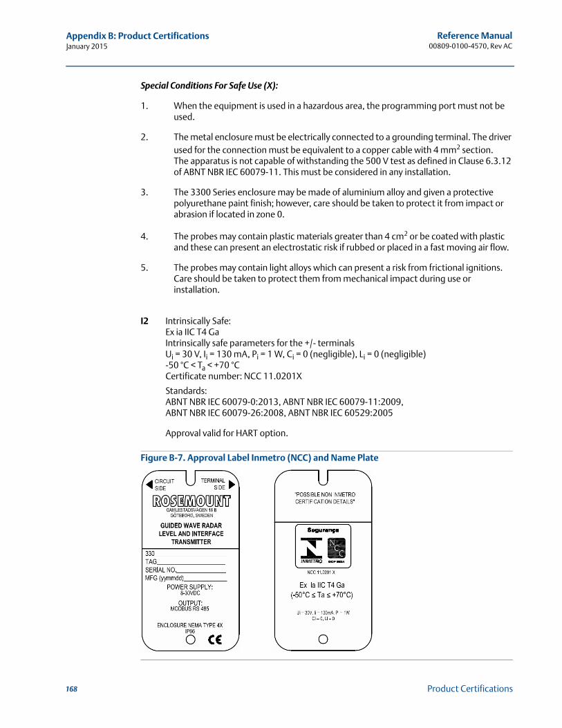
Reference Manual00809-0100-4570, Rev AC
Appendix B: Product CertificationsJanuary 2015
Special Conditions For Safe Use (X):
1. When the equipment is used in a hazardous area, the programming port must not be used.
2. The metal enclosure must be electrically connected to a grounding terminal. The driver used for the connection must be equivalent to a copper cable with 4 mm2 section.The apparatus is not capable of withstanding the 500 V test as defined in Clause 6.3.12 of ABNT NBR IEC 60079-11. This must be considered in any installation.
3. The 3300 Series enclosure may be made of aluminium alloy and given a protective polyurethane paint finish; however, care should be taken to protect it from impact or abrasion if located in zone 0.
4. The probes may contain plastic materials greater than 4 cm2 or be coated with plastic and these can present an electrostatic risk if rubbed or placed in a fast moving air flow.
5. The probes may contain light alloys which can present a risk from frictional ignitions. Care should be taken to protect them from mechanical impact during use or installation.
I2 Intrinsically Safe: Ex ia IIC T4 GaIntrinsically safe parameters for the +/- terminalsUi = 30 V, Ii = 130 mA, Pi = 1 W, Ci = 0 (negligible), Li = 0 (negligible)-50 °C < Ta < +70 °CCertificate number: NCC 11.0201X
Standards: ABNT NBR IEC 60079-0:2013, ABNT NBR IEC 60079-11:2009, ABNT NBR IEC 60079-26:2008, ABNT NBR IEC 60529:2005
Approval valid for HART option.
Figure B-7. Approval Label Inmetro (NCC) and Name Plate
168 Product Certifications

Reference Manual 00809-0100-4570, Rev AC
Appendix B: Product CertificationsJanuary 2015
B.3.5 Chinese certifications
National Supervision and Inspection Center for Explosion Protection and Safety of Instrumentation (NEPSI) approvalsE3 Flameproof: GYJ12.1037X
Ex d ia IIC T6~T4 Gb, DIP A21 TA85 °C~TA135 °C IP66Um = 250 VApproval valid for HART and Modbus® options.
I3 Intrinsically Safe: GYJ11.1537X
Ex ia IIC T4 (-50 °C < Ta < +70 °C)Ui = 30 Vdc, Ii = 130 mA, Pi = 1.0 W, Ci 0nF, Li 0 μHApproval valid for the HART option.
Special Conditions For Safe Use (X):
Refer to Certificates GYJ 11.1537X and GYJ12.1037X.
B.3.6 Japanese certifications
Technology Institution of Industrial Safety (TIIS) approvalE4 Flameproof with intrinsically safe probe: TC18544, TC18545
Transmitter: Ex d [ia] IIB T6 (Ta, max = 60 °C)
Um = 250 V
Probe: Ex ia IIB T6
Uo = 25.2 V, Io = 159 mA, Po = 1.0 W
Approval valid for HART option.
Installation drawing: 03300-00408
Special Conditions for Safe Use (X):
See certificate for details.
169Product Certifications
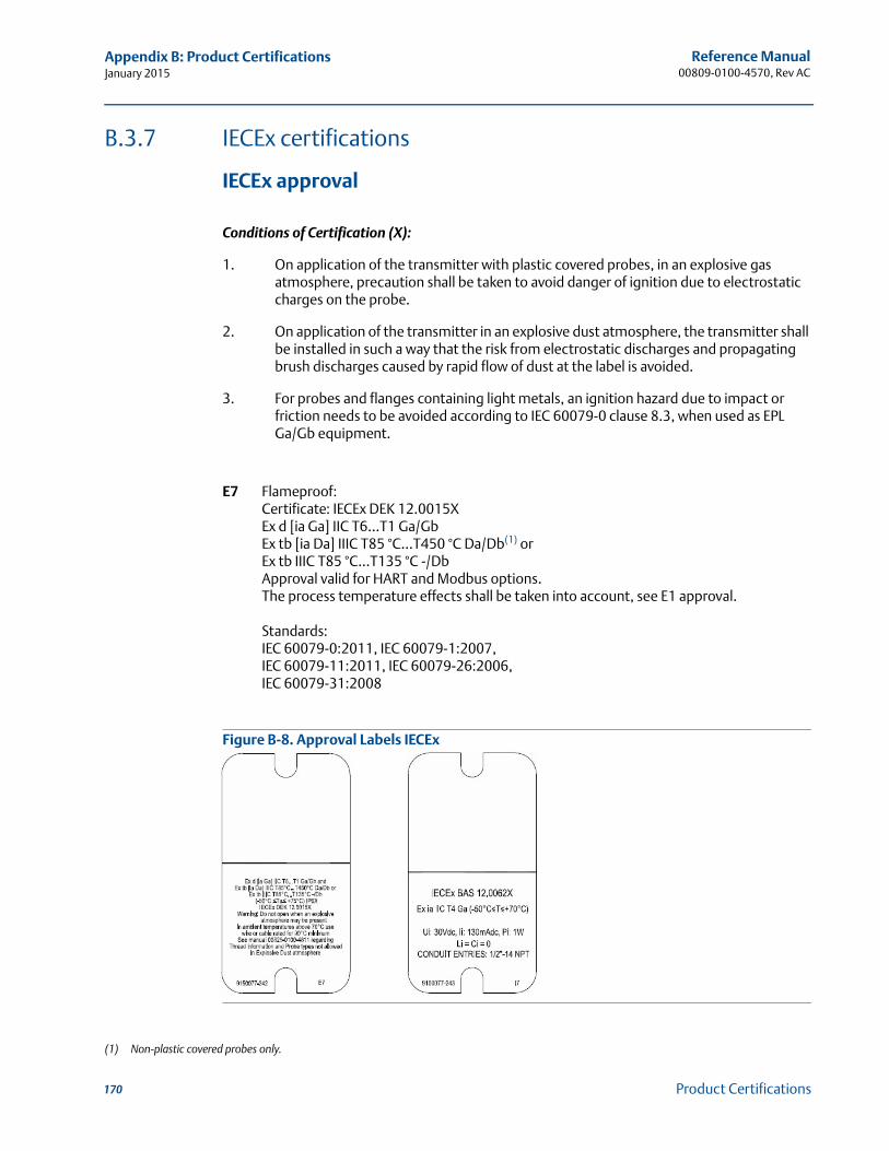
Reference Manual00809-0100-4570, Rev AC
Appendix B: Product CertificationsJanuary 2015
B.3.7 IECEx certifications
IECEx approval
Conditions of Certification (X):
1. On application of the transmitter with plastic covered probes, in an explosive gas atmosphere, precaution shall be taken to avoid danger of ignition due to electrostatic charges on the probe.
2. On application of the transmitter in an explosive dust atmosphere, the transmitter shall be installed in such a way that the risk from electrostatic discharges and propagating brush discharges caused by rapid flow of dust at the label is avoided.
3. For probes and flanges containing light metals, an ignition hazard due to impact or friction needs to be avoided according to IEC 60079-0 clause 8.3, when used as EPL Ga/Gb equipment.
E7 Flameproof: Certificate: IECEx DEK 12.0015XEx d [ia Ga] IIC T6...T1 Ga/GbEx tb [ia Da] IIIC T85 °C...T450 °C Da/Db(1) orEx tb IIIC T85 °C...T135 °C -/DbApproval valid for HART and Modbus options.The process temperature effects shall be taken into account, see E1 approval.
Standards:IEC 60079-0:2011, IEC 60079-1:2007, IEC 60079-11:2011, IEC 60079-26:2006, IEC 60079-31:2008
Figure B-8. Approval Labels IECEx
(1) Non-plastic covered probes only.
170 Product Certifications
Reference Manual 00809-0100-4570, Rev AC
Appendix B: Product CertificationsJanuary 2015
Conditions of Certification (X):
1. The apparatus is not capable of withstanding the 500V test as defined in Clause 6.3.13 of EN60079-11:2012. This must be considered in any installation.
2. The Rosemount 3300 Series enclosure is made of aluminum alloy and given a protective polyurethane paint finish; however, care should be taken to protect it from impact or abrasion if located in zone 0.
3. The probes may contain plastic materials greater than 4 cm2 or be coated with plastic and these can present an electrostatic risk if rubbed or placed in a fast moving air flow.
4. The probes may contain light alloys which can present a risk from frictional ignitions. Care should be taken to protect them from mechanical impact during use or installation.
I7 Intrinsic safety:Certificate: IECEx BAS 12.0062XEx ia IIC T4 (Ta 60 °C) IP66Ui = 30 V, Ii = 130 mA, Pi = 1 W, Ci = 0 nF, Li = 0 mHApproval valid for HART option.
Conditions of Certification (X):
1. The apparatus is not capable of withstanding the 500V test as defined in Clause 6.3.13 of EN60079-11:2012. This must be considered in any installation.
2. The Rosemount 3300 Series enclosure is made of aluminum alloy and given a protective polyurethane paint finish; however, care should be taken to protect it from impact or abrasion.
3. The probes may contain light alloys which can present a risk from frictional ignitions. Care should be taken to protect them from mechanical impact during use or installation.
4. The probes may contain plastic materials greater than 4 cm2 or be coated with plastic and these can present an electrostatic risk if rubbed or placed in a fast moving air flow.
5. The cable entry must use a suitable Certified Cable Gland which provides strain relief and any unused openings to the equipment must be blanked off to maintain a degree of protection of at least IP66.
N7 Type N approvals: non-sparking/intrinsic safetyCertificate: IECEx BAS 12.0061XEx ic nA IIC T4 Gc (-50 °C < Ta < +70 °C)
Standards:IEC 60079-0:2011, IEC 60079-11:2001, IEC 60079-31:2008, IEC 60079-1:2007,IEC 60079-26:2006
171Product Certifications
Reference Manual00809-0100-4570, Rev AC
Appendix B: Product CertificationsJanuary 2015
B.4 Other certifications
Overfill protection
U1 WHG Overfill Approval:TÜV-tested and approved by DIBt for overfill protection according to the German WHG regulations.Certificate: Z-65.16-416Available for HART option.
B.5 Approval drawings
This section contains Factory Mutual, Canadian Standards and TIIS installation drawings. You must follow the installation guidelines presented in order to maintain certified ratings for installed transmitters.
This section contains the following drawings:
Rosemount drawing 9150077-944, Issue 5:System control drawing for hazardous location installation of intrinsically safe FM approved apparatus.
Rosemount drawing 9150077-945, Issue 4:Installation drawing for hazardous location installation of CSA approved apparatus.
TIIS drawing TIIS-R-IS 03300-00408:Installation drawing for hazardous location installation of TIIS approved apparatus.
172 Product Certifications
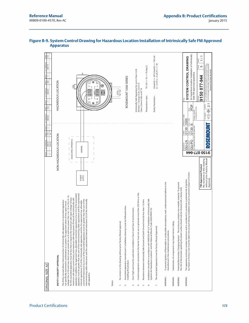
Reference Manual 00809-0100-4570, Rev AC
Appendix B: Product CertificationsJanuary 2015
Figure B-9. System Control Drawing for Hazardous Location Installation of Intrinsically Safe FM Approved Apparatus
FM A
ppro
ved
Prod
uct
No
revi
sion
s to
this
dra
win
gw
ithou
t prio
r Fac
tory
Mut
ual
App
rova
l.
SME-
2917
0139
1IS
SUE
CH
. OR
DER
No
WEE
KIS
SUE
CH
. OR
DER
No
WEE
KIS
SUE
CH
. OR
DER
No
WEE
KIS
SUE
CH
. OR
DER
No
WEE
KA3
OR
IGIN
AL S
IZE
GU
-LN
0139
3300
GU
-PO
6PD
F
9150 077-944
9150
077
-944
0139
SYST
EM C
ON
TRO
L D
RA
WIN
Gfo
r haz
ardo
us lo
catio
n in
stal
latio
n of
Intri
nsic
ally
Safe
FM
app
rove
d ap
para
tus
51
/ 1
ISSU
ED B
Y
APPR
OVE
D B
Y
WEE
K
WEE
K
PRO
DU
CT
CO
DE
DO
C. T
YPE
FILE
TITL
E
DW
G N
O.
ISSU
ESH
EET
SCAL
E 2:1
1 ST
AN
GLE
FIN
ISH
, UN
LESS
OTH
ERW
ISE
STAT
ED:
ALL
DIM
ENSI
ON
S AR
E IN
MIL
LIM
ETR
ES.
The
cop
yrig
ht/o
wne
rshi
p of
this
docu
men
t is
and
will
rem
ain
ours
.T
he d
ocum
ent m
ust n
ot b
e us
ed w
ithou
t our
aut
horiz
atio
n or
bro
ught
to t
he k
now
ledg
e of
a th
ird p
arty
. Con
trave
ntio
n w
ill be
pro
secu
ted.
Ros
emou
nt T
ank
Rad
ar A
B, S
wed
en
ASS
OC
IATE
D A
PPA
RATU
S
BA
RR
IER
PO
WE
R
SU
PP
LY
RO
SE
MO
UN
T 3
30
0 S
ER
IES
Intr
insi
ca
lly
Sa
fe A
pp
ara
tus
for
use
in
Cla
ss I
, II,
III,
Div
isio
n 1
, Gro
up
s A
, B, C
, D, E
, F, G
Cla
ss I
, Zo
ne
0, A
Ex
ia
IIC
T4
Tem
pe
ratu
re c
lass
:T
4 (
-50
<=
Ta
<=
70
de
g C
)
En
tity
Pa
ram
ete
rs :
Vm
ax
(Ui)
<=
30
V, I
ma
x(I
i) <
= 1
30
mA
Ci
= 0
nF,
Li
= 0
uH
, Pi
<=
1 W
HA
ZA
RD
OU
S L
OC
AT
ION
NO
N-H
AZ
AR
DO
US
LO
CA
TIO
NEN
TITY
CO
NC
EPT
APP
RO
VAL
Th
e E
nti
ty c
on
ce
pt
all
ow
s in
terc
on
ne
cti
on
of
intr
insi
ca
lly
sa
fe a
pp
ara
tus
to a
sso
cia
ted
ap
pa
ratu
s
no
t sp
ec
ific
all
y e
xa
min
ed
in
co
mb
ina
tio
n a
s a
sy
ste
m.T
he
ap
pro
ve
d v
alu
es
of
ma
x. o
pe
n c
irc
uit
vo
lta
ge
(V
oc
or
Vt)
an
d m
ax
. sh
ort
cir
cu
it c
urr
en
t (I
sc o
r It
) a
nd
ma
x. p
ow
er
(Vo
c x
Isc
/ 4
) o
r (V
t x
It
/ 4
),
for
the
ass
oc
iate
d a
pp
ara
tus
mu
st b
e l
ess
th
an
or
eq
ua
l to
th
e m
ax
imu
m s
afe
in
pu
t v
olt
ag
e (
Vm
ax
),
ma
xim
um
sa
fe i
np
ut
cu
rre
nt
(Im
ax
), a
nd
ma
xim
um
sa
fe i
np
ut
po
we
r (P
ma
x)
of
the
in
trin
sic
all
y s
afe
ap
pa
ratu
s. I
n a
dd
itio
n, t
he
ap
pro
ve
d m
ax
. all
ow
ab
le c
on
ne
cte
d c
ap
ac
ita
nc
e (
Ca
or
Co
) o
f th
e a
sso
cia
ted
ap
pa
ratu
s m
ust
be
gre
ate
r th
an
th
e s
um
of
the
in
terc
on
ne
cti
ng
ca
ble
ca
pa
cit
an
ce
an
d t
he
un
pro
tec
ted
inte
rna
l c
ap
ac
ita
nc
e (
Ci)
of
the
in
trin
sic
all
y s
afe
ap
pa
ratu
s, a
nd
th
e t
he
ap
pro
ve
d m
ax
. all
ow
ab
le
co
nn
ec
ted
in
du
cta
nc
e (
La
or
Lo
) o
f th
e a
sso
cia
ted
ap
pa
ratu
s m
ust
be
gre
ate
r th
an
th
e s
um
of
the
inte
rco
nn
ec
tin
g c
ab
le i
nd
uc
tan
ce
an
d t
he
un
pro
tec
ted
in
tern
al
ind
uc
tan
ce
(L
i) o
f th
e i
ntr
insi
ca
lly
safe
ap
pa
ratu
s.
No
tes:
1.
No
re
vis
ion
to
th
is d
raw
ing
wit
ho
ut
pri
or
Fa
cto
ry M
utu
al
ap
pro
va
l.
2.
Ass
oc
iate
d a
pp
ara
tus
ma
nu
fac
ture
r's
inst
all
ati
on
dra
win
g m
ust
e b
e f
oll
ow
ed
wh
en
inst
all
ing
th
is p
rod
uc
t.
3.
Du
st-T
igth
se
al
mu
st b
e u
sed
wh
en
in
sta
lle
d i
n C
lass
II
an
d C
lass
III
en
vir
on
me
nts
.
4.
Co
ntr
ol
eq
uip
me
nt
co
nn
ec
ted
to
th
e b
arr
ier
mu
st n
ot
use
or
ge
ne
rate
mo
re t
ha
n 2
50
Vrm
s o
r V
dc
.
5.
Re
sist
an
ce
be
twe
en
In
trin
sic
all
y S
afe
Gro
un
d a
nd
Ea
rth
Gro
un
d m
ust
be
le
ss t
ha
n 1
.0 o
hm
.
6.
Inst
all
ati
on
s sh
ou
ld b
e i
n a
cc
ord
an
ce
wit
h A
NS
I/IS
A-R
P1
2.6
"In
sta
lla
tio
n o
f In
trin
sic
all
y S
afe
Sy
ste
ms
for
Ha
zard
ou
s L
oc
ati
on
s" a
nd
th
e N
ati
on
al
Ele
ctr
ic C
od
e (
AN
SI/
NF
PA
70
).
7.
Th
e a
sso
cia
ted
ap
pa
ratu
s m
ust
be
Fa
cto
ry M
utu
al
Ap
pro
ve
d.
2SM
E-55
0306
433
SME-
5913
0805
4SM
E-71
1911
44
SME-
7961
1420
5
WA
RNIN
G :
To
pre
ven
t ig
nit
ion
of f
lam
mab
le o
r co
mb
ust
ible
atm
osp
her
es, r
ead
, u
nd
erst
and
an
d a
dh
ere
to t
he
man
ufa
ctu
rer's
live
mai
nte
nan
ce p
roce
du
res.
WA
RNIN
G:
Sub
stit
uti
on
of c
om
po
nen
ts m
ay im
pai
r In
trin
sic
Safe
ty.
WA
RNIN
G:
Pote
nti
al E
lect
rost
atic
Ch
arg
ing
Haz
ard
– T
he
encl
osu
re c
on
tain
s n
on
-met
allic
mat
eria
l. T
o p
reve
nt
the
risk
of e
lect
rost
atic
sp
arki
ng
th
e p
last
ic s
urf
ace
sho
uld
on
ly b
e cl
ean
ed w
ith
a d
amp
clo
th.
WA
RNIN
G:
The
app
arat
us
encl
osu
re c
on
tain
s al
um
inu
m a
nd
is c
on
sid
ered
to
co
nst
itu
te a
po
ten
tial
risk
of i
gn
itio
n
b
y im
pac
t o
r fri
ctio
n. C
are
mu
st b
e ta
ken
into
acc
ou
nt
du
rin
g in
stal
lati
on
an
d u
se to
pre
ven
t im
pac
t o
r fri
ctio
n.
173Product Certifications
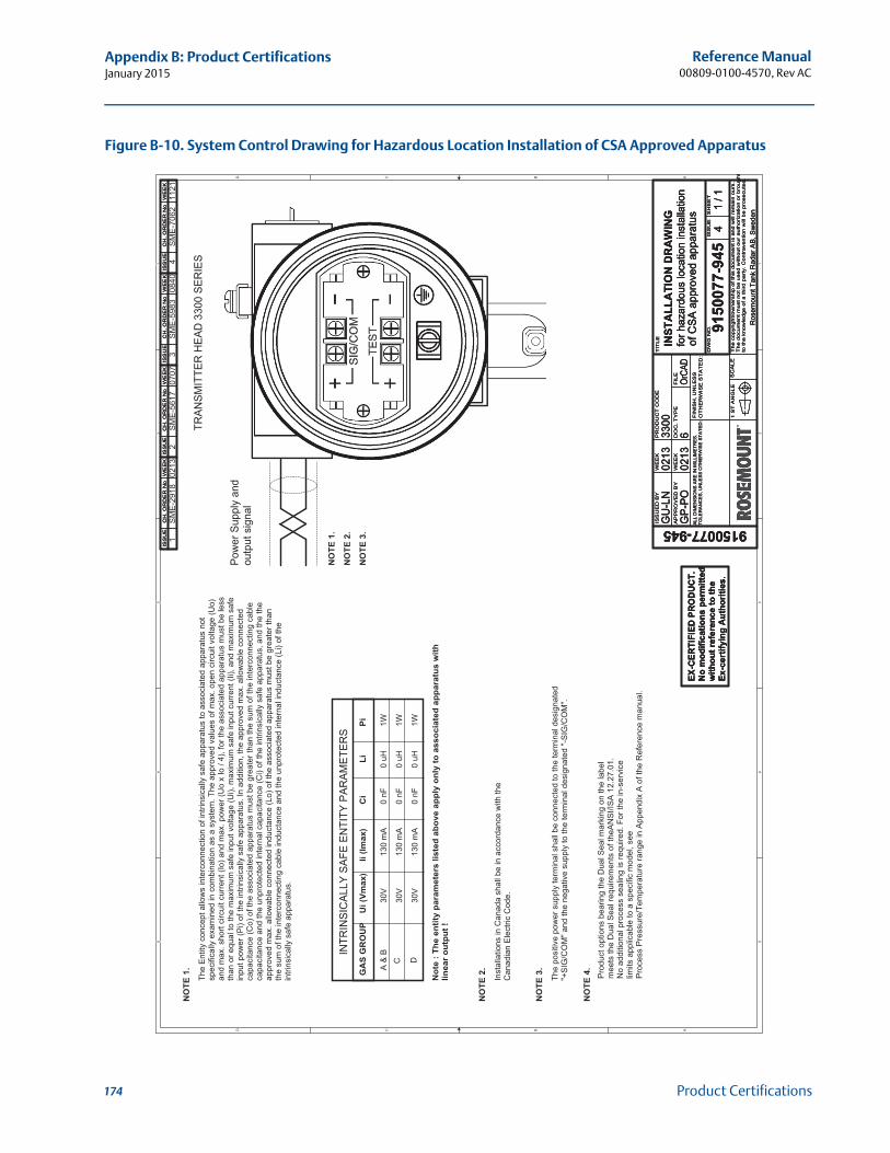
Reference Manual00809-0100-4570, Rev AC
Appendix B: Product CertificationsJanuary 2015
Figure B-10. System Control Drawing for Hazardous Location Installation of CSA Approved Apparatus5 5
4 4
3 3
2 2
1 1
DD
CC
BB
AA
TRAN
SMIT
TER
HEA
D 3
300
SER
IES
The
Entit
y co
ncep
t allo
ws
inte
rcon
nect
ion
of in
trins
ical
ly s
afe
appa
ratu
s to
ass
ocia
ted
appa
ratu
s no
tsp
ecifi
cally
exa
min
ed in
com
bina
tion
as a
sys
tem
. The
app
rove
d va
lues
of m
ax. o
pen
circ
uit v
olta
ge (U
o)an
d m
ax. s
hort
circ
uit c
urre
nt (I
o) a
nd m
ax. p
ower
(Uo
x Io
/ 4)
, for
the
asso
ciat
ed a
ppar
atus
mus
t be
less
than
or e
qual
to th
e m
axim
um s
afe
inpu
t vol
tage
(Ui),
max
imum
saf
e in
put c
urre
nt (I
i), a
nd m
axim
um s
afe
inpu
t pow
er (P
i) of
the
intri
nsic
ally
saf
e ap
para
tus.
In a
dditi
on, t
he a
ppro
ved
max
. allo
wab
le c
onne
cted
capa
cita
nce
(Co)
of t
he a
ssoc
iate
d ap
para
tus
mus
t be
grea
ter t
han
the
sum
of t
he in
terc
onne
ctin
g ca
ble
capa
cita
nce
and
the
unpr
otec
ted
inte
rnal
cap
acita
nce
(Ci)
of th
e in
trins
ical
ly s
afe
appa
ratu
s, a
nd th
e th
eap
prov
ed m
ax. a
llow
able
con
nect
ed in
duct
ance
(Lo)
of t
he a
ssoc
iate
d ap
para
tus
mus
t be
grea
ter t
han
the
sum
of t
he in
terc
onne
ctin
g ca
ble
indu
ctan
ce a
nd th
e un
prot
ecte
d in
tern
al in
duct
ance
(Li)
of th
ein
trins
ical
ly s
afe
appa
ratu
s.
D
INTR
INSI
CAL
LY S
AFE
ENTI
TY P
ARAM
ETER
S
A &
BC
GA
S G
RO
UP
The
posi
tive
pow
er s
uppl
y te
rmin
al s
hall
be c
onne
cted
to th
e te
rmin
al d
esig
nate
d"+
SIG
/CO
M" a
nd th
e ne
gativ
e su
pply
to th
e te
rmin
al d
esig
nate
d "-S
IG/C
OM
".
Inst
alla
tions
in C
anad
a sh
all b
e in
acc
orda
nce
with
the
Can
adia
n El
ectri
c C
ode.
Pow
er S
uppl
y an
dou
tput
sig
nal
Ui (
Vmax
)Ii
(Imax
)C
iLi
Pi
NO
TE 1
.
30V
30V
30V
1W 1W 1W
0 nF
0 nF
0 nF
0 uH
0 uH
0 uH
130
mA
130
mA
130
mA
NO
TE 2
.
NO
TE 1
.
NO
TE 2
.
NO
TE 3
.
Not
e : T
he e
ntity
par
amet
ers
liste
d ab
ove
appl
y on
ly to
ass
ocia
ted
appa
ratu
s w
ithlin
ear o
utpu
t !
NO
TE 3
.
Prod
uct o
ptio
ns b
earin
g th
e D
ual S
eal m
arki
ng o
n th
e la
bel
mee
ts th
e D
ual S
eal r
equi
rem
ents
of t
heAN
SI/IS
A 12
.27.
01.
No
addi
tiona
l pro
cess
sea
ling
is re
quire
d. F
or th
e in
-ser
vice
limits
app
licab
le to
a s
peci
fic m
odel
, see
Proc
ess
Pres
sure
/Tem
pera
ture
rang
e in
App
endi
x A
of th
e R
efer
ence
man
ual.
NO
TE 4
.
43
12
SME-
5617
SME-
5983
SME-
7062
SME-
2918
0213
0707
0840
1121
ISS
UE
CH
. O
RD
ER
No
WE
EK
ISS
UE
CH
. O
RD
ER
No
WE
EK
ISS
UE
CH
. O
RD
ER
No
WE
EK
ISS
UE
CH
. O
RD
ER
No
WE
EK
ISS
UE
CH
. O
RD
ER
No
WE
EK
ISS
UE
CH
. O
RD
ER
No
WE
EK
ISS
UE
CH
. O
RD
ER
No
WE
EK
ISS
UE
CH
. O
RD
ER
No
WE
EK
ISS
UE
CH
. O
RD
ER
No
WE
EK
ISS
UE
CH
. O
RD
ER
No
WE
EK
ISS
UE
CH
. O
RD
ER
No
WE
EK
ISS
UE
CH
. O
RD
ER
No
WE
EK
ISS
UE
D B
Y
AP
PR
OV
ED
BY
WE
EK
WE
EK
PR
OD
UC
T C
OD
E
DO
C. T
YP
EF
ILE
TIT
LE
TE
EH
SE
US
SI.
ON
GW
D
SC
AL
E1 S
T A
NG
LE
FIN
ISH
, U
NLE
SS
OT
HE
RW
ISE
ST
AT
ED
:
Th
e c
op
yrig
ht/
ow
ne
rsh
ip o
f th
is d
ocu
me
nt is
an
d w
ill r
em
ain
ou
rs.
Th
e d
ocu
me
nt m
ust
no
t b
e u
sed
with
ou
t o
ur
au
tho
riza
tion
or
bro
ug
ht
to th
e k
no
wle
dg
e o
f a
th
ird
pa
rty.
Co
ntr
ave
ntio
n w
ill b
e p
rose
cute
d.
Ros
emou
nt T
ank
Rad
ar A
B, S
wed
en
ALL
DIM
ENSI
ON
S AR
E IN
MIL
LIM
ETR
ES.
TOLE
RAN
CES
, UN
LESS
OTH
ERW
ISE
STAT
ED:
GU
-LN
0213
3300
GP-
PO6
OrCA
D
9150
077-
945
0213
INST
ALL
ATI
ON
DR
AW
ING
for h
azar
dous
loca
tion
inst
alla
tion
41
/ 1
of C
SA a
ppro
ved
appa
ratu
s
ISS
UE
D B
Y
AP
PR
OV
ED
BY
WE
EK
WE
EK
PR
OD
UC
T C
OD
E
DO
C. T
YP
EF
ILE
TIT
LE
TE
EH
SE
US
SI.
ON
GW
D
SC
AL
E1 S
T A
NG
LE
FIN
ISH
, U
NLE
SS
OT
HE
RW
ISE
ST
AT
ED
:
Th
e c
op
yrig
ht/
ow
ne
rsh
ip o
f th
is d
ocu
me
nt is
an
d w
ill r
em
ain
ou
rs.
Th
e d
ocu
me
nt m
ust
no
t b
e u
sed
with
ou
t o
ur
au
tho
riza
tion
or
bro
ug
ht
to th
e k
no
wle
dg
e o
f a
th
ird
pa
rty.
Co
ntr
ave
ntio
n w
ill b
e p
rose
cute
d.
Ros
emou
nt T
ank
Rad
ar A
B, S
wed
en
ALL
DIM
ENSI
ON
S AR
E IN
MIL
LIM
ETR
ES.
TOLE
RAN
CES
, UN
LESS
OTH
ERW
ISE
STAT
ED:
GU
-LN
0213
3300
GP-
PO6
OrCA
D
9150
077-
945
0213
INST
ALL
ATI
ON
DR
AW
ING
for h
azar
dous
loca
tion
inst
alla
tion
41
/ 1
of C
SA a
ppro
ved
appa
ratu
sEX
-CER
TIFI
ED P
RO
DU
CT.
No
mod
ifica
tions
per
mitt
edw
ithou
t ref
eren
ce to
the
Ex-c
ertif
ying
Aut
horit
ies.
EX-C
ERTI
FIED
PR
OD
UC
T.N
o m
odifi
catio
ns p
erm
itted
with
out r
efer
ence
to th
eEx
-cer
tifyi
ng A
utho
ritie
s.
EX-C
ERTI
FIED
PR
OD
UC
T.N
o m
odifi
catio
ns p
erm
itted
with
out r
efer
ence
to th
eEx
-cer
tifyi
ng A
utho
ritie
s.
174 Product Certifications
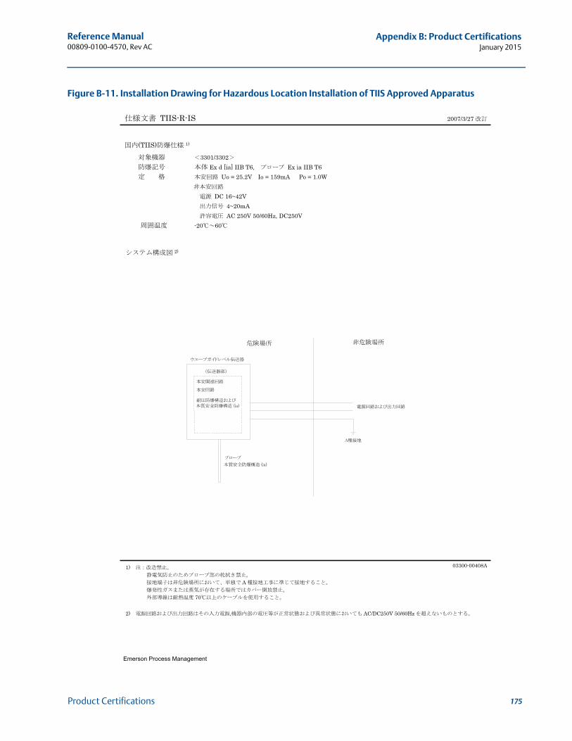
Reference Manual 00809-0100-4570, Rev AC
Appendix B: Product CertificationsJanuary 2015
Figure B-11. Installation Drawing for Hazardous Location Installation of TIIS Approved Apparatus
Emerson Process Management
TIIS-R-IS 2007/3/27
(TIIS) 1)
3301/3302 Ex d [ia] IIB T6, Ex ia IIB T6 Uo = 25.2V Io = 159mA Po = 1.0W
DC 16~42V 4~20mA AC 250V 50/60Hz, DC250V
-20 60
1) 03300-00408A
A
70
2) , AC/DC250V 50/60Hz
2)
175Product Certifications

Reference Manual00809-0100-4570, Rev AC
Appendix B: Product CertificationsJanuary 2015
176 Product Certifications
Reference Manual 00809-0100-4811, Rev DA
Appendix C: Rosemount 3300 Series with HART® to Modbus® ConverterJanuary 2015
Appendix C Rosemount 3300 Series with HART® to Modbus® Converter
Safety messages . . . . . . . . . . . . . . . . . . . . . . . . . . . . . . . . . . . . . . . . . . . . . . . . . . . . . . . . . . . . page 177Introduction . . . . . . . . . . . . . . . . . . . . . . . . . . . . . . . . . . . . . . . . . . . . . . . . . . . . . . . . . . . . . . . page 178Workflow . . . . . . . . . . . . . . . . . . . . . . . . . . . . . . . . . . . . . . . . . . . . . . . . . . . . . . . . . . . . . . . . . . page 179Mechanical installation . . . . . . . . . . . . . . . . . . . . . . . . . . . . . . . . . . . . . . . . . . . . . . . . . . . . . . page 179Electrical installation . . . . . . . . . . . . . . . . . . . . . . . . . . . . . . . . . . . . . . . . . . . . . . . . . . . . . . . . page 180Establish HART communication . . . . . . . . . . . . . . . . . . . . . . . . . . . . . . . . . . . . . . . . . . . . . . . page 184Transmitter configuration . . . . . . . . . . . . . . . . . . . . . . . . . . . . . . . . . . . . . . . . . . . . . . . . . . . . page 186Modbus communication protocol configuration . . . . . . . . . . . . . . . . . . . . . . . . . . . . . . . . page 186Alarm handling . . . . . . . . . . . . . . . . . . . . . . . . . . . . . . . . . . . . . . . . . . . . . . . . . . . . . . . . . . . . . page 193Common Modbus host configuration . . . . . . . . . . . . . . . . . . . . . . . . . . . . . . . . . . . . . . . . . . page 195Specific Modbus host configuration . . . . . . . . . . . . . . . . . . . . . . . . . . . . . . . . . . . . . . . . . . . page 199Troubleshooting . . . . . . . . . . . . . . . . . . . . . . . . . . . . . . . . . . . . . . . . . . . . . . . . . . . . . . . . . . . . page 204HMC Firmware Upgrade in Rosemount Radar Master . . . . . . . . . . . . . . . . . . . . . . . . . . . . page 205Specifications . . . . . . . . . . . . . . . . . . . . . . . . . . . . . . . . . . . . . . . . . . . . . . . . . . . . . . . . . . . . . . page 208
C.1 Safety messages
Procedures and instructions in this section may require special precautions to ensure the safety of the personnel performing the operations. Information that raises potential safety issues is
indicated by a warning symbol ( ). Please refer to the following safety messages before performing an operation preceded by this symbol.
177Rosemount 3300 Series with HART® to Modbus® Converter
Reference Manual00809-0100-4811, Rev DA
Appendix C: Rosemount 3300 Series with HART® to Modbus® ConverterJanuary 2015
C.2 Introduction
The Rosemount 3300 Series Transmitter is a Modbus compatible measurement device that supports communication with a Remote Terminal Unit (RTU) using a subset of read, write, and diagnostic commands used by most Modbus-compatible host controllers. The transmitter also supports communication through Levelmaster and Modbus ASCII protocols.
The HART to Modbus Converter (HMC) module is located inside the Rosemount 3300 transmitter enclosure and provides power to and communicates with the transmitter through a HART interface.
Failure to follow safe installation and service guidelines could result in death or serious injury.
Make sure the transmitter is installed by qualified personnel and in accordance with applicable code of practice.
Use the equipment only as specified in this manual. Failure to do so may impair the protection provided by the equipment.
Do not perform any services other than those contained in this manual unless you are qualified.
Explosions could result in death or serious injury.
Verify that the operating environment of the transmitter is consistent with the appropriate hazardous locations specifications.
To prevent ignition of flammable or combustible atmospheres, disconnect power before servicing.
Before connecting a HART®- based communicator in an explosive atmosphere, make sure the instruments in the loop are installed in accordance with intrinsically safe or non-incendive field wiring practices.
To avoid process leaks, only use O-ring designed to seal with the corresponding flange adapter.
Electrical shock can result in death or serious injury.
Avoid contact with the leads and terminals. High voltage that may be present on leads can cause electrical shock.
Make sure the main power to the Rosemount 3300 Series Transmitter is off and the lines to any other external power source are disconnected or not powered while wiring the transmitter.
Probes with non-conducting surfaces
Probes covered with plastic and/or with plastic discs may generate an ignition-capable level of electrostatic charge under certain extreme conditions. Therefore, when the probe is used in a potentially explosive atmosphere, appropriate measures must be taken to prevent electrostatic discharge.
178 Rosemount 3300 Series with HART® to Modbus® Converter
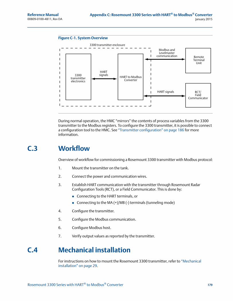
Reference Manual 00809-0100-4811, Rev DA
Appendix C: Rosemount 3300 Series with HART® to Modbus® ConverterJanuary 2015
Figure C-1. System Overview
During normal operation, the HMC “mirrors” the contents of process variables from the 3300 transmitter to the Modbus registers. To configure the 3300 transmitter, it is possible to connect a configuration tool to the HMC. See “Transmitter configuration” on page 186 for more information.
C.3 Workflow
Overview of workflow for commissioning a Rosemount 3300 transmitter with Modbus protocol:
1. Mount the transmitter on the tank.
2. Connect the power and communication wires.
3. Establish HART communication with the transmitter through Rosemount Radar Configuration Tools (RCT), or a Field Communicator. This is done by:
Connecting to the HART terminals, or
Connecting to the MA (+)/MB (-) terminals (tunneling mode)
4. Configure the transmitter.
5. Configure the Modbus communication.
6. Configure Modbus host.
7. Verify output values as reported by the transmitter.
C.4 Mechanical installation
For instructions on how to mount the Rosemount 3300 transmitter, refer to “Mechanical installation” on page 29.
3300transmitterelectronics
HARTsignals
HART to ModbusConverter
Modbus and Levelmaster
communication Remote Terminal
Unit
RCT/Field
Communicator
HART signals
3300 transmitter enclosure
179Rosemount 3300 Series with HART® to Modbus® Converter

Reference Manual00809-0100-4811, Rev DA
Appendix C: Rosemount 3300 Series with HART® to Modbus® ConverterJanuary 2015
C.5 Electrical installation
NoteFor general electrical installation requirements, including grounding requirements, refer to “Electrical installation” on page 52.
To connect the Rosemount 3300 Series:
1. Disconnect/shut off the electrical power to transmitter head and then open the instrument cover. Do not remove the cover in an explosive atmosphere with a live circuit.
2. Pull the cable through the cable gland/conduit. For the RS-485 bus, use shielded twisted pair wiring, preferably with an impedance of 120 (typically 24 AWG) in order to comply with the EIA-485 standard and EMC regulations. The maximum cable length is 4000 ft. (1200 m).
3. Make sure that the transmitter housing is grounded, then connect wires according to Figure C-2 and Table C-1. Connect the lead that originates from the “A” line from the RS-485 bus to the terminal marked MB (-), and the lead that originates from the “B” line to the terminal marked MA (+).
4. If it is the last transmitter on the bus, connect the 120 termination resistor.
5. Connect the leads from the positive side of the power supply to the terminal marked PWR +, and the leads from the negative side of the power supply to the terminal marked PWR -. The power supply cables must be suitable for the supply voltage and ambient temperature, and approved for use in hazardous areas, where applicable.
6. Attach and tighten the housing cover. Tighten the cable gland, then plug and seal any unused terminals, and connect the power supply.
180 Rosemount 3300 Series with HART® to Modbus® Converter
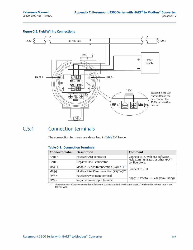
Reference Manual 00809-0100-4811, Rev DA
Appendix C: Rosemount 3300 Series with HART® to Modbus® ConverterJanuary 2015
Figure C-2. Field Wiring Connections
C.5.1 Connection terminals
The connection terminals are described in Table C-1 below:
Table C-1. Connection Terminals
Connector label Description CommentHART + Positive HART connector Connect to PC with RCT software,
Field Communicator, or other HART configurators.HART - Negative HART connector
MA (+) Modbus RS-485 B connection (RX/TX+)(1)
(1) The designation of the connectors do not follow the EIA-485 standard, which states that RX/TX- should be referred to as 'A' and RX/TX+ as 'B'.
Connect to RTUMB (-) Modbus RS-485 A connection (RX/TX-)(1)
PWR + Positive Power input terminalApply +8 Vdc to +30 Vdc (max. rating)
PWR - Negative Power input terminal
RS-485 Bus B
A
Power Supply
HART +
120120
In case it is the last transmitter on the bus, connect the 120termination resistor
120
HART -
181Rosemount 3300 Series with HART® to Modbus® Converter
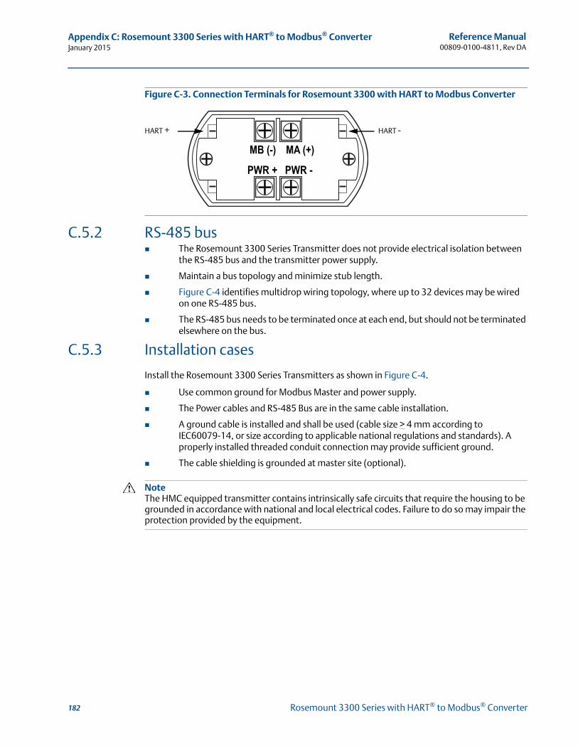
Reference Manual00809-0100-4811, Rev DA
Appendix C: Rosemount 3300 Series with HART® to Modbus® ConverterJanuary 2015
Figure C-3. Connection Terminals for Rosemount 3300 with HART to Modbus Converter
C.5.2 RS-485 bus The Rosemount 3300 Series Transmitter does not provide electrical isolation between
the RS-485 bus and the transmitter power supply.
Maintain a bus topology and minimize stub length.
Figure C-4 identifies multidrop wiring topology, where up to 32 devices may be wired on one RS-485 bus.
The RS-485 bus needs to be terminated once at each end, but should not be terminated elsewhere on the bus.
C.5.3 Installation cases
Install the Rosemount 3300 Series Transmitters as shown in Figure C-4.
Use common ground for Modbus Master and power supply.
The Power cables and RS-485 Bus are in the same cable installation.
A ground cable is installed and shall be used (cable size > 4 mm according to IEC60079-14, or size according to applicable national regulations and standards). A properly installed threaded conduit connection may provide sufficient ground.
The cable shielding is grounded at master site (optional).
NoteThe HMC equipped transmitter contains intrinsically safe circuits that require the housing to be grounded in accordance with national and local electrical codes. Failure to do so may impair the protection provided by the equipment.
HART + HART -
182 Rosemount 3300 Series with HART® to Modbus® Converter
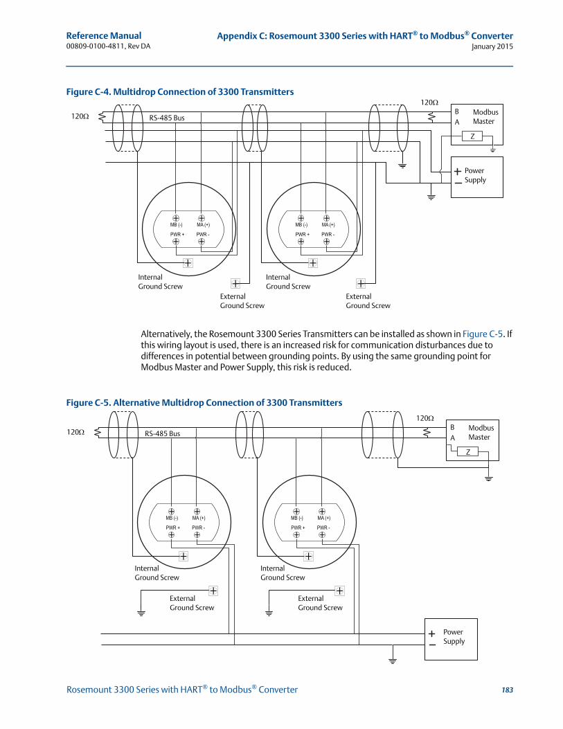
Reference Manual 00809-0100-4811, Rev DA
Appendix C: Rosemount 3300 Series with HART® to Modbus® ConverterJanuary 2015
Figure C-4. Multidrop Connection of 3300 Transmitters
Alternatively, the Rosemount 3300 Series Transmitters can be installed as shown in Figure C-5. If this wiring layout is used, there is an increased risk for communication disturbances due to differences in potential between grounding points. By using the same grounding point for Modbus Master and Power Supply, this risk is reduced.
Figure C-5. Alternative Multidrop Connection of 3300 Transmitters
Power Supply
120
120 RS-485 BusBA
Internal Ground Screw
Modbus Master
Z
Internal Ground Screw
External Ground Screw
External Ground Screw
Power Supply
120
120 RS-485 BusBA
Internal Ground Screw
Modbus Master
Z
Internal Ground Screw
External Ground Screw
External Ground Screw
183Rosemount 3300 Series with HART® to Modbus® Converter
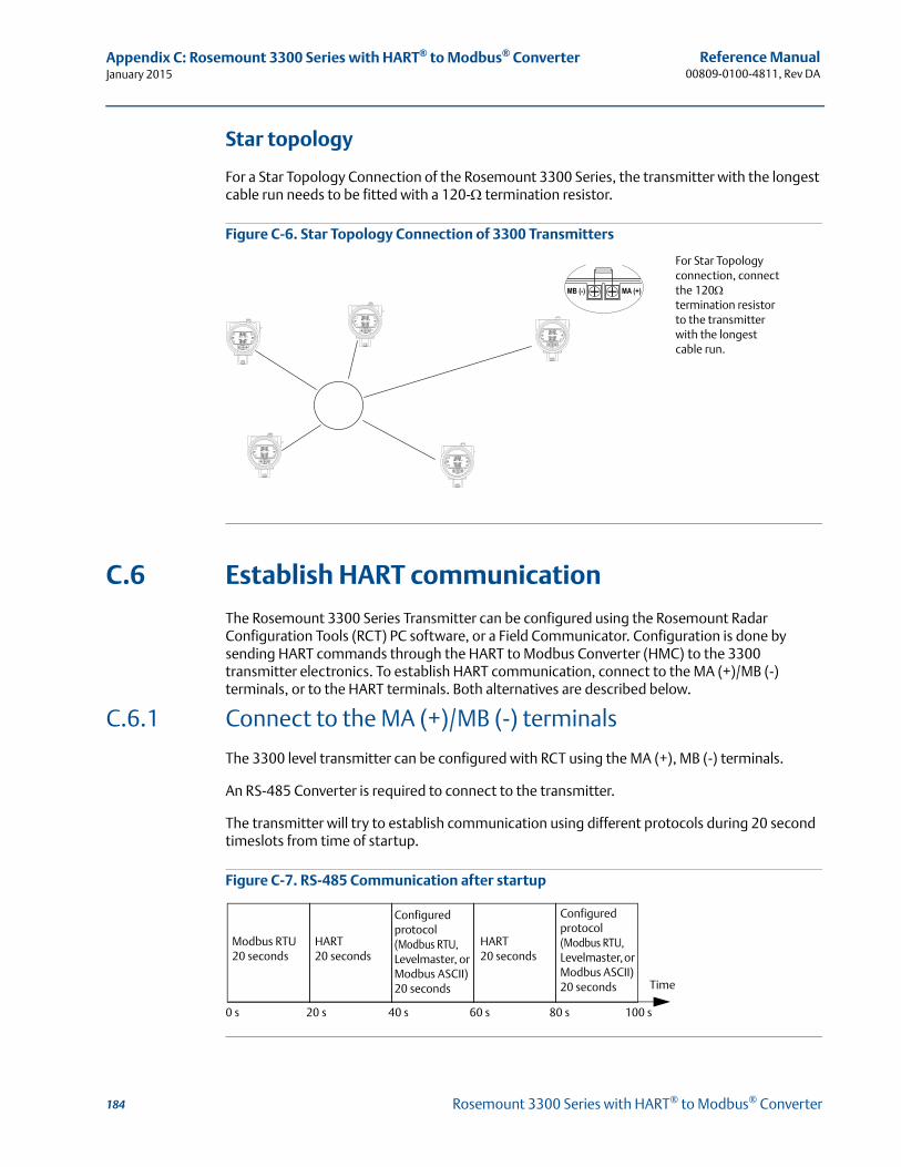
Reference Manual00809-0100-4811, Rev DA
Appendix C: Rosemount 3300 Series with HART® to Modbus® ConverterJanuary 2015
Star topology
For a Star Topology Connection of the Rosemount 3300 Series, the transmitter with the longest cable run needs to be fitted with a 120- termination resistor.
Figure C-6. Star Topology Connection of 3300 Transmitters
C.6 Establish HART communication
The Rosemount 3300 Series Transmitter can be configured using the Rosemount Radar Configuration Tools (RCT) PC software, or a Field Communicator. Configuration is done by sending HART commands through the HART to Modbus Converter (HMC) to the 3300 transmitter electronics. To establish HART communication, connect to the MA (+)/MB (-) terminals, or to the HART terminals. Both alternatives are described below.
C.6.1 Connect to the MA (+)/MB (-) terminals
The 3300 level transmitter can be configured with RCT using the MA (+), MB (-) terminals.
An RS-485 Converter is required to connect to the transmitter.
The transmitter will try to establish communication using different protocols during 20 second timeslots from time of startup.
Figure C-7. RS-485 Communication after startup
For Star Topology connection, connect the 120termination resistor to the transmitter with the longest cable run.
HART20 seconds
Modbus RTU20 seconds
Configured protocol (Modbus RTU, Levelmaster, or Modbus ASCII) 20 seconds
HART20 seconds
Time
0 s 20 s 40 s 60 s 80 s 100 s
Configured protocol (Modbus RTU, Levelmaster, or Modbus ASCII) 20 seconds
184 Rosemount 3300 Series with HART® to Modbus® Converter
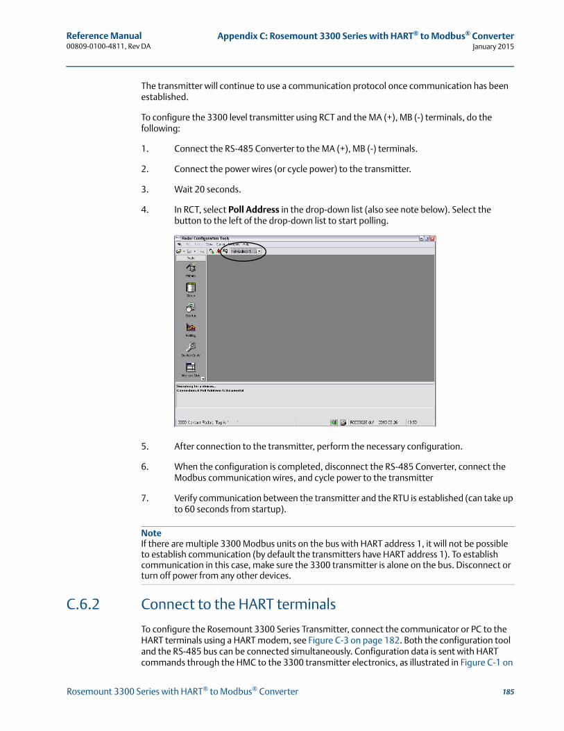
Reference Manual 00809-0100-4811, Rev DA
Appendix C: Rosemount 3300 Series with HART® to Modbus® ConverterJanuary 2015
The transmitter will continue to use a communication protocol once communication has been established.
To configure the 3300 level transmitter using RCT and the MA (+), MB (-) terminals, do the following:
1. Connect the RS-485 Converter to the MA (+), MB (-) terminals.
2. Connect the power wires (or cycle power) to the transmitter.
3. Wait 20 seconds.
4. In RCT, select Poll Address in the drop-down list (also see note below). Select the button to the left of the drop-down list to start polling.
5. After connection to the transmitter, perform the necessary configuration.
6. When the configuration is completed, disconnect the RS-485 Converter, connect the Modbus communication wires, and cycle power to the transmitter
7. Verify communication between the transmitter and the RTU is established (can take up to 60 seconds from startup).
NoteIf there are multiple 3300 Modbus units on the bus with HART address 1, it will not be possible to establish communication (by default the transmitters have HART address 1). To establish communication in this case, make sure the 3300 transmitter is alone on the bus. Disconnect or turn off power from any other devices.
C.6.2 Connect to the HART terminals
To configure the Rosemount 3300 Series Transmitter, connect the communicator or PC to the HART terminals using a HART modem, see Figure C-3 on page 182. Both the configuration tool and the RS-485 bus can be connected simultaneously. Configuration data is sent with HART commands through the HMC to the 3300 transmitter electronics, as illustrated in Figure C-1 on
185Rosemount 3300 Series with HART® to Modbus® Converter
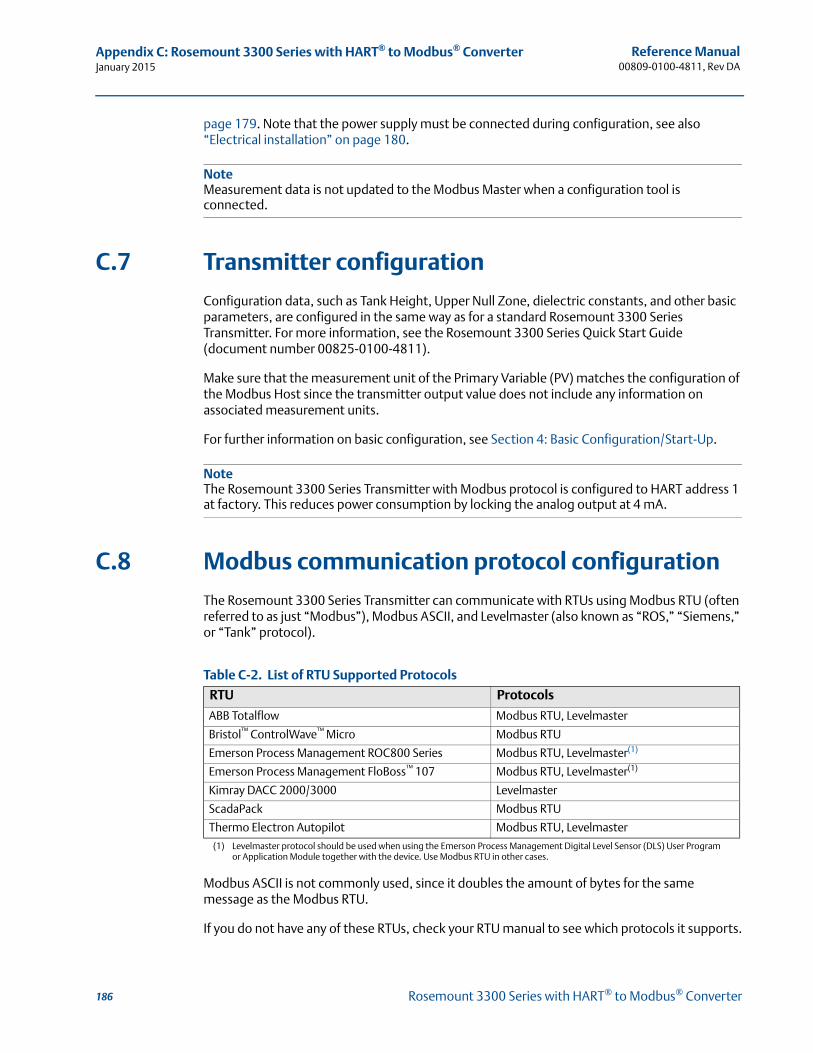
Reference Manual00809-0100-4811, Rev DA
Appendix C: Rosemount 3300 Series with HART® to Modbus® ConverterJanuary 2015
page 179. Note that the power supply must be connected during configuration, see also “Electrical installation” on page 180.
NoteMeasurement data is not updated to the Modbus Master when a configuration tool is connected.
C.7 Transmitter configuration
Configuration data, such as Tank Height, Upper Null Zone, dielectric constants, and other basic parameters, are configured in the same way as for a standard Rosemount 3300 Series Transmitter. For more information, see the Rosemount 3300 Series Quick Start Guide (document number 00825-0100-4811).
Make sure that the measurement unit of the Primary Variable (PV) matches the configuration of the Modbus Host since the transmitter output value does not include any information on associated measurement units.
For further information on basic configuration, see Section 4: Basic Configuration/Start-Up.
NoteThe Rosemount 3300 Series Transmitter with Modbus protocol is configured to HART address 1 at factory. This reduces power consumption by locking the analog output at 4 mA.
C.8 Modbus communication protocol configuration
The Rosemount 3300 Series Transmitter can communicate with RTUs using Modbus RTU (often referred to as just “Modbus”), Modbus ASCII, and Levelmaster (also known as “ROS,” “Siemens,” or “Tank” protocol).
Table C-2. List of RTU Supported Protocols
Modbus ASCII is not commonly used, since it doubles the amount of bytes for the same message as the Modbus RTU.
If you do not have any of these RTUs, check your RTU manual to see which protocols it supports.
RTU Protocols
ABB Totalflow Modbus RTU, Levelmaster
Bristol™ ControlWave™ Micro Modbus RTU
Emerson Process Management ROC800 Series Modbus RTU, Levelmaster(1)
(1) Levelmaster protocol should be used when using the Emerson Process Management Digital Level Sensor (DLS) User Program or Application Module together with the device. Use Modbus RTU in other cases.
Emerson Process Management FloBoss™ 107 Modbus RTU, Levelmaster(1)
Kimray DACC 2000/3000 Levelmaster
ScadaPack Modbus RTU
Thermo Electron Autopilot Modbus RTU, Levelmaster
186 Rosemount 3300 Series with HART® to Modbus® Converter
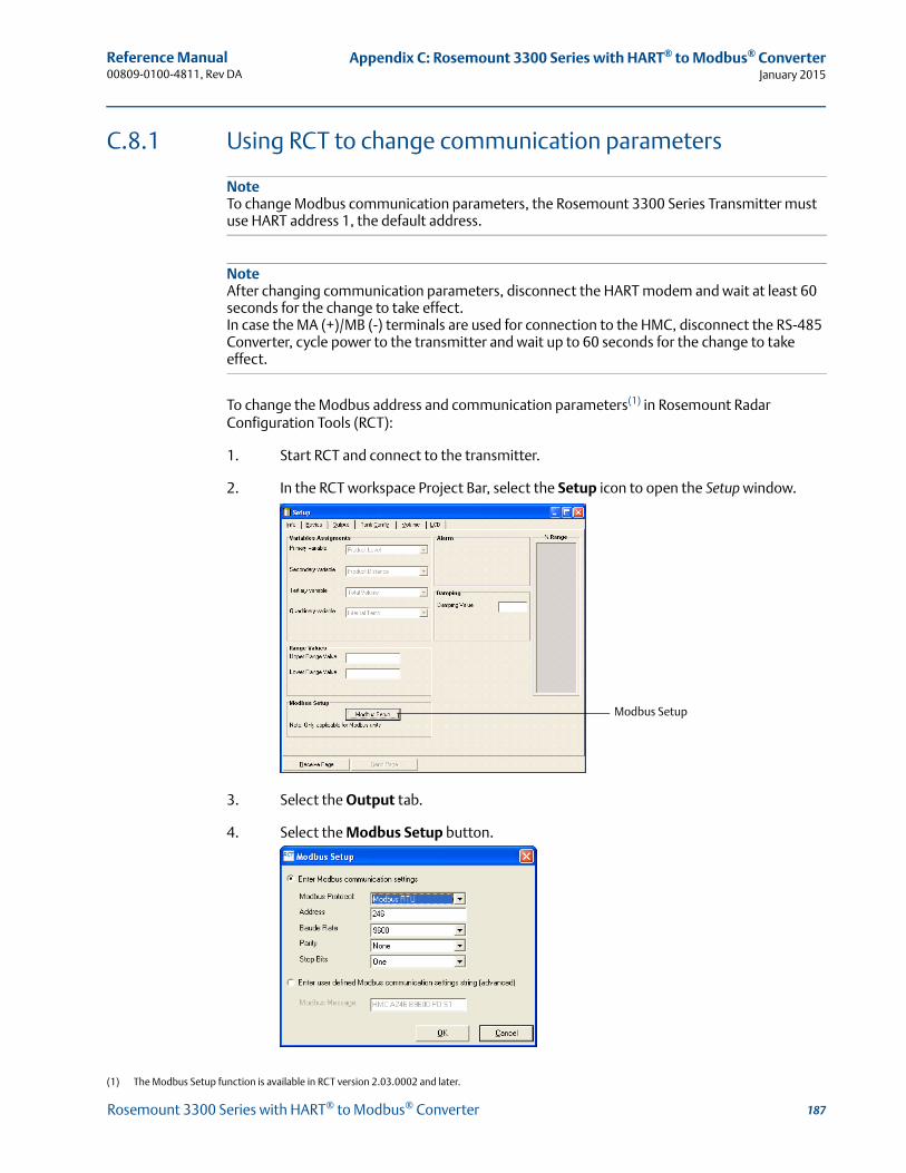
Reference Manual 00809-0100-4811, Rev DA
Appendix C: Rosemount 3300 Series with HART® to Modbus® ConverterJanuary 2015
C.8.1 Using RCT to change communication parameters
NoteTo change Modbus communication parameters, the Rosemount 3300 Series Transmitter must use HART address 1, the default address.
NoteAfter changing communication parameters, disconnect the HART modem and wait at least 60 seconds for the change to take effect.In case the MA (+)/MB (-) terminals are used for connection to the HMC, disconnect the RS-485 Converter, cycle power to the transmitter and wait up to 60 seconds for the change to take effect.
To change the Modbus address and communication parameters(1) in Rosemount Radar Configuration Tools (RCT):
1. Start RCT and connect to the transmitter.
2. In the RCT workspace Project Bar, select the Setup icon to open the Setup window.
3. Select the Output tab.
4. Select the Modbus Setup button.
(1) The Modbus Setup function is available in RCT version 2.03.0002 and later.
Modbus Setup
187Rosemount 3300 Series with HART® to Modbus® Converter
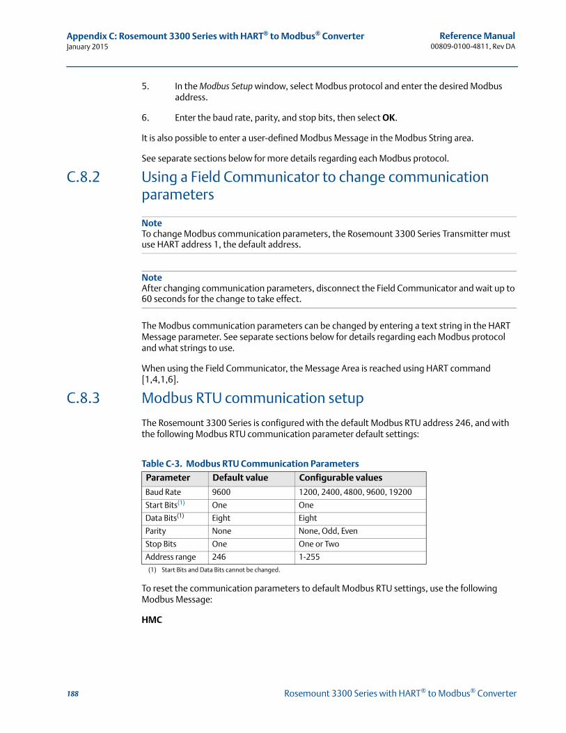
Reference Manual00809-0100-4811, Rev DA
Appendix C: Rosemount 3300 Series with HART® to Modbus® ConverterJanuary 2015
5. In the Modbus Setup window, select Modbus protocol and enter the desired Modbus address.
6. Enter the baud rate, parity, and stop bits, then select OK.
It is also possible to enter a user-defined Modbus Message in the Modbus String area.
See separate sections below for more details regarding each Modbus protocol.
C.8.2 Using a Field Communicator to change communication parameters
NoteTo change Modbus communication parameters, the Rosemount 3300 Series Transmitter must use HART address 1, the default address.
NoteAfter changing communication parameters, disconnect the Field Communicator and wait up to 60 seconds for the change to take effect.
The Modbus communication parameters can be changed by entering a text string in the HART Message parameter. See separate sections below for details regarding each Modbus protocol and what strings to use.
When using the Field Communicator, the Message Area is reached using HART command [1,4,1,6].
C.8.3 Modbus RTU communication setup
The Rosemount 3300 Series is configured with the default Modbus RTU address 246, and with the following Modbus RTU communication parameter default settings:
Table C-3. Modbus RTU Communication Parameters
To reset the communication parameters to default Modbus RTU settings, use the following Modbus Message:
HMC
Parameter Default value Configurable values
Baud Rate 9600 1200, 2400, 4800, 9600, 19200
Start Bits(1)
(1) Start Bits and Data Bits cannot be changed.
One One
Data Bits(1) Eight Eight
Parity None None, Odd, Even
Stop Bits One One or Two
Address range 246 1-255
188 Rosemount 3300 Series with HART® to Modbus® Converter
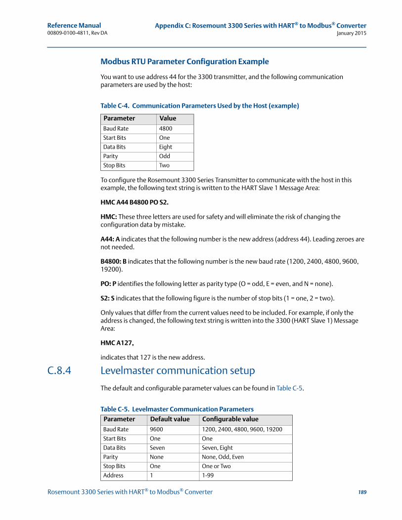
Reference Manual 00809-0100-4811, Rev DA
Appendix C: Rosemount 3300 Series with HART® to Modbus® ConverterJanuary 2015
Modbus RTU Parameter Configuration Example
You want to use address 44 for the 3300 transmitter, and the following communication parameters are used by the host:
Table C-4. Communication Parameters Used by the Host (example)
To configure the Rosemount 3300 Series Transmitter to communicate with the host in this example, the following text string is written to the HART Slave 1 Message Area:
HMC A44 B4800 PO S2.
HMC: These three letters are used for safety and will eliminate the risk of changing the configuration data by mistake.
A44: A indicates that the following number is the new address (address 44). Leading zeroes are not needed.
B4800: B indicates that the following number is the new baud rate (1200, 2400, 4800, 9600, 19200).
PO: P identifies the following letter as parity type (O = odd, E = even, and N = none).
S2: S indicates that the following figure is the number of stop bits (1 = one, 2 = two).
Only values that differ from the current values need to be included. For example, if only the address is changed, the following text string is written into the 3300 (HART Slave 1) Message Area:
HMC A127,
indicates that 127 is the new address.
C.8.4 Levelmaster communication setup
The default and configurable parameter values can be found in Table C-5.
Table C-5. Levelmaster Communication Parameters
Parameter Value
Baud Rate 4800
Start Bits One
Data Bits Eight
Parity Odd
Stop Bits Two
Parameter Default value Configurable value
Baud Rate 9600 1200, 2400, 4800, 9600, 19200
Start Bits One One
Data Bits Seven Seven, Eight
Parity None None, Odd, Even
Stop Bits One One or Two
Address 1 1-99
189Rosemount 3300 Series with HART® to Modbus® Converter
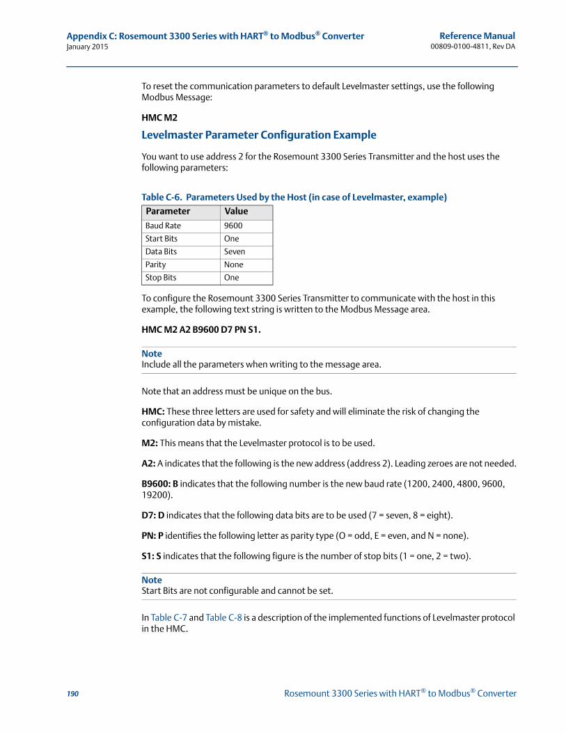
Reference Manual00809-0100-4811, Rev DA
Appendix C: Rosemount 3300 Series with HART® to Modbus® ConverterJanuary 2015
To reset the communication parameters to default Levelmaster settings, use the following Modbus Message:
HMC M2
Levelmaster Parameter Configuration Example
You want to use address 2 for the Rosemount 3300 Series Transmitter and the host uses the following parameters:
Table C-6. Parameters Used by the Host (in case of Levelmaster, example)
To configure the Rosemount 3300 Series Transmitter to communicate with the host in this example, the following text string is written to the Modbus Message area.
HMC M2 A2 B9600 D7 PN S1.
NoteInclude all the parameters when writing to the message area.
Note that an address must be unique on the bus.
HMC: These three letters are used for safety and will eliminate the risk of changing the configuration data by mistake.
M2: This means that the Levelmaster protocol is to be used.
A2: A indicates that the following is the new address (address 2). Leading zeroes are not needed.
B9600: B indicates that the following number is the new baud rate (1200, 2400, 4800, 9600, 19200).
D7: D indicates that the following data bits are to be used (7 = seven, 8 = eight).
PN: P identifies the following letter as parity type (O = odd, E = even, and N = none).
S1: S indicates that the following figure is the number of stop bits (1 = one, 2 = two).
Note Start Bits are not configurable and cannot be set.
In Table C-7 and Table C-8 is a description of the implemented functions of Levelmaster protocol in the HMC.
Parameter Value
Baud Rate 9600
Start Bits One
Data Bits Seven
Parity None
Stop Bits One
190 Rosemount 3300 Series with HART® to Modbus® Converter
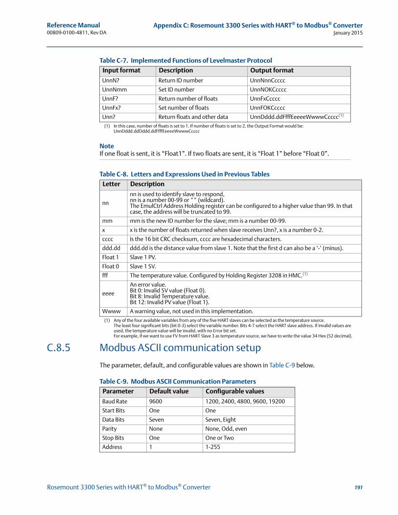
Reference Manual 00809-0100-4811, Rev DA
Appendix C: Rosemount 3300 Series with HART® to Modbus® ConverterJanuary 2015
Table C-7. Implemented Functions of Levelmaster Protocol
Table C-8. Letters and Expressions Used in Previous Tables
C.8.5 Modbus ASCII communication setup
The parameter, default, and configurable values are shown in Table C-9 below.
Table C-9. Modbus ASCII Communication Parameters
Input format Description Output format
UnnN? Return ID number UnnNnnCcccc
UnnNmm Set ID number UnnNOKCcccc
UnnF? Return number of floats UnnFxCcccc
UnnFx? Set number of floats UnnFOKCcccc
Unn? Return floats and other data UnnDddd.ddFfffEeeeeWwwwCcccc(1)
(1) In this case, number of floats is set to 1. If number of floats is set to 2, the Output Format would be: UnnDddd.ddDddd.ddFfffEeeeeWwwwCcccc
NoteIf one float is sent, it is “Float1”. If two floats are sent, it is “Float 1” before “Float 0”.
Letter Description
nn
nn is used to identify slave to respond,nn is a number 00-99 or ** (wildcard).The EmulCtrl Address Holding register can be configured to a higher value than 99. In that case, the address will be truncated to 99.
mm mm is the new ID number for the slave; mm is a number 00-99.
x x is the number of floats returned when slave receives Unn?, x is a number 0-2.
cccc Is the 16 bit CRC checksum, cccc are hexadecimal characters.
ddd.dd ddd.dd is the distance value from slave 1. Note that the first d can also be a ‘-’ (minus).
Float 1 Slave 1 PV.
Float 0 Slave 1 SV.
fff The temperature value. Configured by Holding Register 3208 in HMC.(1)
(1) Any of the four available variables from any of the five HART slaves can be selected as the temperature source. The least four significant bits (bit 0-3) select the variable number. Bits 4-7 select the HART slave address. If invalid values are used, the temperature value will be invalid, with no Error bit set.For example, if we want to use FV from HART Slave 3 as temperature source, we have to write the value 34 Hex (52 decimal).
eeee
An error value.Bit 0: Invalid SV value (Float 0).Bit 8: Invalid Temperature value.Bit 12: Invalid PV value (Float 1).
Wwww A warning value, not used in this implementation.
Parameter Default value Configurable values
Baud Rate 9600 1200, 2400, 4800, 9600, 19200
Start Bits One One
Data Bits Seven Seven, Eight
Parity None None, Odd, even
Stop Bits One One or Two
Address 1 1-255
191Rosemount 3300 Series with HART® to Modbus® Converter

Reference Manual00809-0100-4811, Rev DA
Appendix C: Rosemount 3300 Series with HART® to Modbus® ConverterJanuary 2015
To reset the communication parameters to default Modbus ASCII settings, use the following Modbus Message:
HMC M1
Modbus ASCII Parameter Configuration Example
You want to use address 246 for the Rosemount 3300 Series Transmitter and the host uses the following parameters:
Table C-10. Parameters Used by the Host (in case of Modbus ASCII, example)
To configure the Rosemount 3300 Series Transmitter to communicate with the host in this example, the following text string is written to the Modbus Message area.
HMC M1 A246 B9600 D7 PN S1.
NoteInclude all the parameters when writing to the message area.
Note that an address must be unique on the bus.
HMC: These three letters are used for safety and will eliminate the risk of changing the configuration data by mistake.
M1: This means that the Modbus ASCII protocol is to be used.
A246: A indicates that the following number is the new address (address 246). Leading zeroes are not needed.
B9600: B indicates that the following number is the new baud rate (1200, 2400, 4800, 9600, 19200).
D7: D indicates that the following data bits are to be used (7 = seven, 8 = eight).
PN: P identifies the following letter as parity type (O = odd, E = even, and N = none).
S1: S indicates that the following figure is the number of stop bits (1 = one, 2 = two).
NoteStart Bits are not configurable and cannot be set.
Parameter ValueBaud Rate 9600Start Bits OneData Bits SevenParity NoneStop Bits One
192 Rosemount 3300 Series with HART® to Modbus® Converter
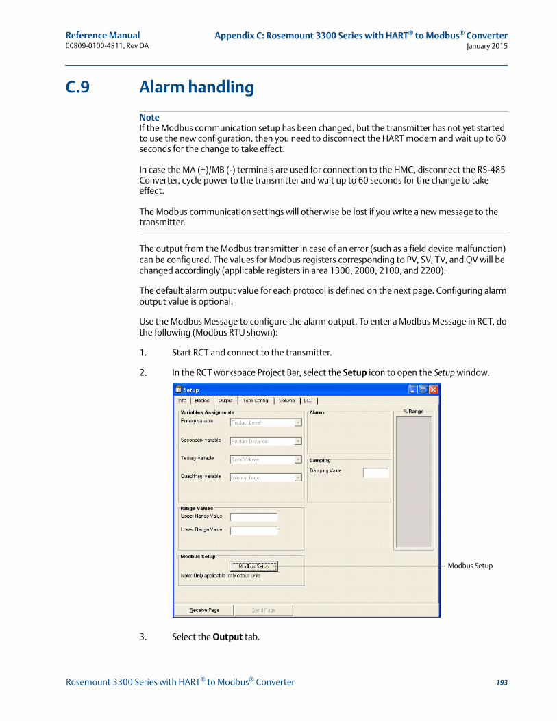
Reference Manual 00809-0100-4811, Rev DA
Appendix C: Rosemount 3300 Series with HART® to Modbus® ConverterJanuary 2015
C.9 Alarm handling
NoteIf the Modbus communication setup has been changed, but the transmitter has not yet started to use the new configuration, then you need to disconnect the HART modem and wait up to 60 seconds for the change to take effect.
In case the MA (+)/MB (-) terminals are used for connection to the HMC, disconnect the RS-485 Converter, cycle power to the transmitter and wait up to 60 seconds for the change to take effect.
The Modbus communication settings will otherwise be lost if you write a new message to the transmitter.
The output from the Modbus transmitter in case of an error (such as a field device malfunction) can be configured. The values for Modbus registers corresponding to PV, SV, TV, and QV will be changed accordingly (applicable registers in area 1300, 2000, 2100, and 2200).
The default alarm output value for each protocol is defined on the next page. Configuring alarm output value is optional.
Use the Modbus Message to configure the alarm output. To enter a Modbus Message in RCT, do the following (Modbus RTU shown):
1. Start RCT and connect to the transmitter.
2. In the RCT workspace Project Bar, select the Setup icon to open the Setup window.
3. Select the Output tab.
Modbus Setup
193Rosemount 3300 Series with HART® to Modbus® Converter
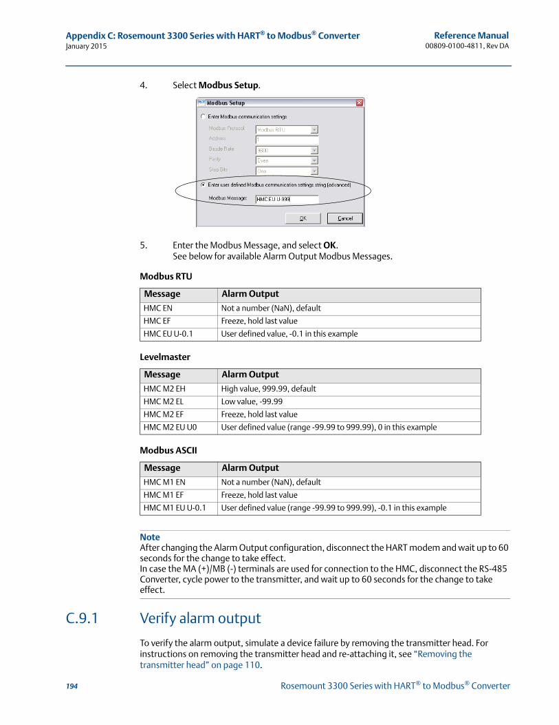
Reference Manual00809-0100-4811, Rev DA
Appendix C: Rosemount 3300 Series with HART® to Modbus® ConverterJanuary 2015
4. Select Modbus Setup.
5. Enter the Modbus Message, and select OK.See below for available Alarm Output Modbus Messages.
Modbus RTU
Levelmaster
Modbus ASCII
NoteAfter changing the Alarm Output configuration, disconnect the HART modem and wait up to 60 seconds for the change to take effect.In case the MA (+)/MB (-) terminals are used for connection to the HMC, disconnect the RS-485 Converter, cycle power to the transmitter, and wait up to 60 seconds for the change to take effect.
C.9.1 Verify alarm output
To verify the alarm output, simulate a device failure by removing the transmitter head. For instructions on removing the transmitter head and re-attaching it, see “Removing the transmitter head” on page 110.
Message Alarm Output
HMC EN Not a number (NaN), default
HMC EF Freeze, hold last value
HMC EU U-0.1 User defined value, -0.1 in this example
Message Alarm Output
HMC M2 EH High value, 999.99, default
HMC M2 EL Low value, -99.99
HMC M2 EF Freeze, hold last value
HMC M2 EU U0 User defined value (range -99.99 to 999.99), 0 in this example
Message Alarm Output
HMC M1 EN Not a number (NaN), default
HMC M1 EF Freeze, hold last value
HMC M1 EU U-0.1 User defined value (range -99.99 to 999.99), -0.1 in this example
194 Rosemount 3300 Series with HART® to Modbus® Converter
Reference Manual 00809-0100-4811, Rev DA
Appendix C: Rosemount 3300 Series with HART® to Modbus® ConverterJanuary 2015
C.9.2 Use status information to evaluate measurement validity
The transmitter updates status information about the current measurement, and this status information is available as a bitfield register through Modbus communication.
By monitoring the status information it is possible to determine if the current measurement output value is valid. See “Common Modbus host configuration” on page 195 for details about the individual status bits.
C.9.3 Use Heartbeat to detect errors
By reading and evaluating the Heartbeat value from the device, it is possible to verify that the communication link between the transmitter, HMC, RTU and even the control system communicating with the RTU is working.
Assign Heartbeat to one of the transmitter variables (SV, TV, or QV). Heartbeat is increased by one for each measurement cycle in the device (until it eventually starts over at zero again).
In case this value is not updated, it means that the communication link is broken.
C.10 Common Modbus host configuration
When using Modbus RTU or Modbus ASCII, the registers to receive status and variables must be configured in the host system.
The transmission of single-precision (4 bytes) IEEE 754 floating point numbers can be rearranged in different byte orders specified by the Floating Point Format Code. The format code information, stated for each Remote Terminal Unit (RTU) respectively, specifies which registers to poll from the Rosemount 3300 Series Transmitter in order for the RTU to correctly interpret floating point numbers. The byte transmission order for each format code is demonstrated in Table C-11 below.
Table C-11. Byte Transmission Order is specified by the Floating Point Format Code
NoteSome Modbus hosts cannot read the information described here using Input Registers (Modbus function code 4). The Input Register information can also be read using Holding Register (Function code 3). In this case, Input Register number + 5000 is used as Holding Register number.
Between host system and device, it is recommended to use 60 seconds or less between polls, and three retries.
Format code Byte transmission order Description
0 [AB] [CD] Straight word order, most significant byte first
1 [CD] [AB] Inverse word order, most significant byte first
2 [DC] [BA] Inverse word order, least significant byte first
3 [BA] [DC] Straight word order, least significant byte first
195Rosemount 3300 Series with HART® to Modbus® Converter
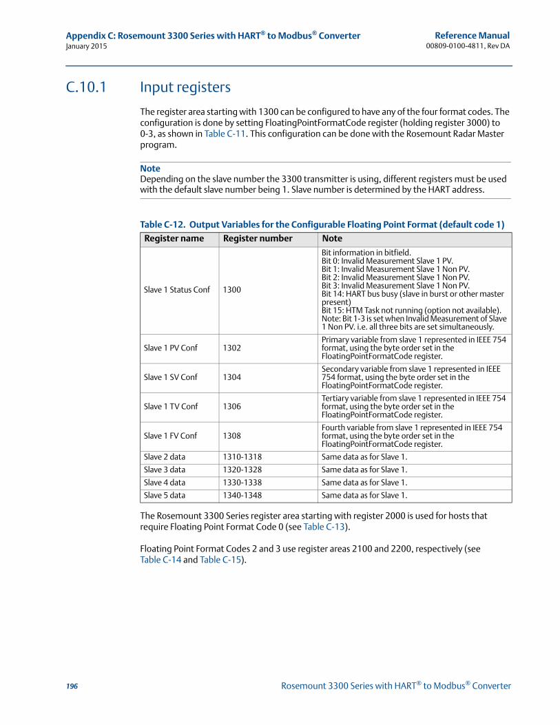
Reference Manual00809-0100-4811, Rev DA
Appendix C: Rosemount 3300 Series with HART® to Modbus® ConverterJanuary 2015
C.10.1 Input registers
The register area starting with 1300 can be configured to have any of the four format codes. The configuration is done by setting FloatingPointFormatCode register (holding register 3000) to 0-3, as shown in Table C-11. This configuration can be done with the Rosemount Radar Master program.
NoteDepending on the slave number the 3300 transmitter is using, different registers must be used with the default slave number being 1. Slave number is determined by the HART address.
Table C-12. Output Variables for the Configurable Floating Point Format (default code 1)
The Rosemount 3300 Series register area starting with register 2000 is used for hosts that require Floating Point Format Code 0 (see Table C-13).
Floating Point Format Codes 2 and 3 use register areas 2100 and 2200, respectively (see Table C-14 and Table C-15).
Register name Register number Note
Slave 1 Status Conf 1300
Bit information in bitfield.Bit 0: Invalid Measurement Slave 1 PV.Bit 1: Invalid Measurement Slave 1 Non PV.Bit 2: Invalid Measurement Slave 1 Non PV.Bit 3: Invalid Measurement Slave 1 Non PV.Bit 14: HART bus busy (slave in burst or other master present)Bit 15: HTM Task not running (option not available).Note: Bit 1-3 is set when Invalid Measurement of Slave 1 Non PV. i.e. all three bits are set simultaneously.
Slave 1 PV Conf 1302Primary variable from slave 1 represented in IEEE 754 format, using the byte order set in the FloatingPointFormatCode register.
Slave 1 SV Conf 1304Secondary variable from slave 1 represented in IEEE 754 format, using the byte order set in the FloatingPointFormatCode register.
Slave 1 TV Conf 1306Tertiary variable from slave 1 represented in IEEE 754 format, using the byte order set in the FloatingPointFormatCode register.
Slave 1 FV Conf 1308Fourth variable from slave 1 represented in IEEE 754 format, using the byte order set in the FloatingPointFormatCode register.
Slave 2 data 1310-1318 Same data as for Slave 1.
Slave 3 data 1320-1328 Same data as for Slave 1.
Slave 4 data 1330-1338 Same data as for Slave 1.
Slave 5 data 1340-1348 Same data as for Slave 1.
196 Rosemount 3300 Series with HART® to Modbus® Converter
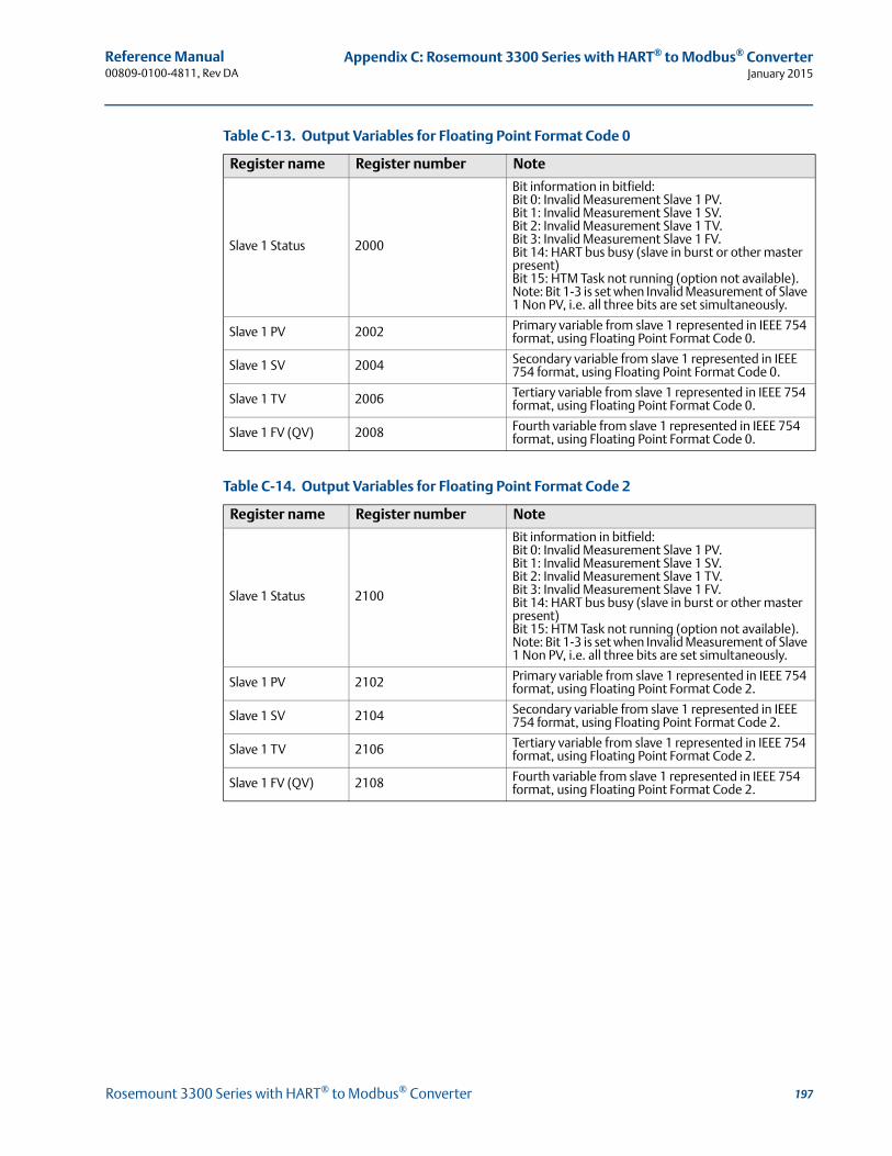
Reference Manual 00809-0100-4811, Rev DA
Appendix C: Rosemount 3300 Series with HART® to Modbus® ConverterJanuary 2015
Table C-13. Output Variables for Floating Point Format Code 0
Table C-14. Output Variables for Floating Point Format Code 2
Register name Register number Note
Slave 1 Status 2000
Bit information in bitfield:Bit 0: Invalid Measurement Slave 1 PV.Bit 1: Invalid Measurement Slave 1 SV.Bit 2: Invalid Measurement Slave 1 TV. Bit 3: Invalid Measurement Slave 1 FV.Bit 14: HART bus busy (slave in burst or other master present)Bit 15: HTM Task not running (option not available).Note: Bit 1-3 is set when Invalid Measurement of Slave 1 Non PV, i.e. all three bits are set simultaneously.
Slave 1 PV 2002 Primary variable from slave 1 represented in IEEE 754 format, using Floating Point Format Code 0.
Slave 1 SV 2004 Secondary variable from slave 1 represented in IEEE 754 format, using Floating Point Format Code 0.
Slave 1 TV 2006 Tertiary variable from slave 1 represented in IEEE 754 format, using Floating Point Format Code 0.
Slave 1 FV (QV) 2008 Fourth variable from slave 1 represented in IEEE 754 format, using Floating Point Format Code 0.
Register name Register number Note
Slave 1 Status 2100
Bit information in bitfield:Bit 0: Invalid Measurement Slave 1 PV.Bit 1: Invalid Measurement Slave 1 SV.Bit 2: Invalid Measurement Slave 1 TV. Bit 3: Invalid Measurement Slave 1 FV.Bit 14: HART bus busy (slave in burst or other master present)Bit 15: HTM Task not running (option not available).Note: Bit 1-3 is set when Invalid Measurement of Slave 1 Non PV, i.e. all three bits are set simultaneously.
Slave 1 PV 2102 Primary variable from slave 1 represented in IEEE 754 format, using Floating Point Format Code 2.
Slave 1 SV 2104 Secondary variable from slave 1 represented in IEEE 754 format, using Floating Point Format Code 2.
Slave 1 TV 2106 Tertiary variable from slave 1 represented in IEEE 754 format, using Floating Point Format Code 2.
Slave 1 FV (QV) 2108 Fourth variable from slave 1 represented in IEEE 754 format, using Floating Point Format Code 2.
197Rosemount 3300 Series with HART® to Modbus® Converter
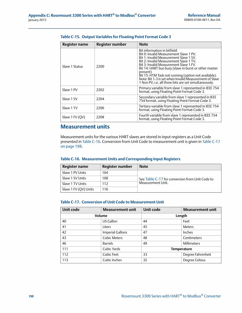
Reference Manual00809-0100-4811, Rev DA
Appendix C: Rosemount 3300 Series with HART® to Modbus® ConverterJanuary 2015
Table C-15. Output Variables for Floating Point Format Code 3
Measurement units
Measurement units for the various HART slaves are stored in input registers as a Unit Code presented in Table C-16. Conversion from Unit Code to measurement unit is given in Table C-17 on page 198.
Table C-16. Measurement Units and Corresponding Input Registers
Table C-17. Conversion of Unit Code to Measurement Unit
Register name Register number Note
Slave 1 Status 2200
Bit information in bitfield:Bit 0: Invalid Measurement Slave 1 PV.Bit 1: Invalid Measurement Slave 1 SV.Bit 2: Invalid Measurement Slave 1 TV. Bit 3: Invalid Measurement Slave 1 FV.Bit 14: HART bus busy (slave in burst or other master present)Bit 15: HTM Task not running (option not available).Note: Bit 1-3 is set when Invalid Measurement of Slave 1 Non PV, i.e. all three bits are set simultaneously.
Slave 1 PV 2202 Primary variable from slave 1 represented in IEEE 754 format, using Floating Point Format Code 3.
Slave 1 SV 2204 Secondary variable from slave 1 represented in IEEE 754 format, using Floating Point Format Code 3.
Slave 1 TV 2206 Tertiary variable from slave 1 represented in IEEE 754 format, using Floating Point Format Code 3.
Slave 1 FV (QV) 2208 Fourth variable from slave 1 represented in IEEE 754 format, using Floating Point Format Code 3.
Register name Register number Note
Slave 1 PV Units 104
See Table C-17 for conversion from Unit Code to Measurement Unit.
Slave 1 SV Units 108
Slave 1 TV Units 112
Slave 1 FV (QV) Units 116
Unit code Measurement unit Unit code Measurement unit
Volume Length
40 US Gallon 44 Feet
41 Liters 45 Meters
42 Imperial Gallons 47 Inches
43 Cubic Meters 48 Centimeters
46 Barrels 49 Millimeters
111 Cubic Yards Temperature
112 Cubic Feet 33 Degree Fahrenheit
113 Cubic Inches 32 Degree Celsius
198 Rosemount 3300 Series with HART® to Modbus® Converter
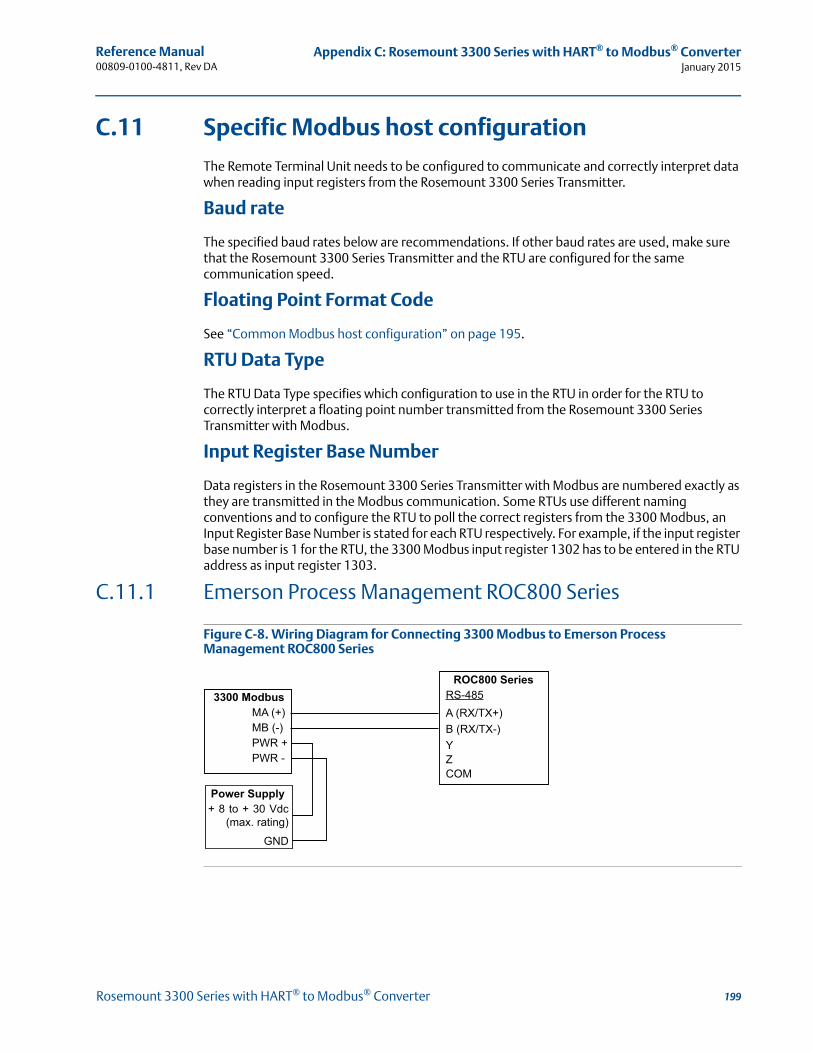
Reference Manual 00809-0100-4811, Rev DA
Appendix C: Rosemount 3300 Series with HART® to Modbus® ConverterJanuary 2015
C.11 Specific Modbus host configuration
The Remote Terminal Unit needs to be configured to communicate and correctly interpret data when reading input registers from the Rosemount 3300 Series Transmitter.
Baud rate
The specified baud rates below are recommendations. If other baud rates are used, make sure that the Rosemount 3300 Series Transmitter and the RTU are configured for the same communication speed.
Floating Point Format Code
See “Common Modbus host configuration” on page 195.
RTU Data Type
The RTU Data Type specifies which configuration to use in the RTU in order for the RTU to correctly interpret a floating point number transmitted from the Rosemount 3300 Series Transmitter with Modbus.
Input Register Base Number
Data registers in the Rosemount 3300 Series Transmitter with Modbus are numbered exactly as they are transmitted in the Modbus communication. Some RTUs use different naming conventions and to configure the RTU to poll the correct registers from the 3300 Modbus, an Input Register Base Number is stated for each RTU respectively. For example, if the input register base number is 1 for the RTU, the 3300 Modbus input register 1302 has to be entered in the RTU address as input register 1303.
C.11.1 Emerson Process Management ROC800 Series
Figure C-8. Wiring Diagram for Connecting 3300 Modbus to Emerson Process Management ROC800 Series
RS-485A (RX/TX+)B (RX/TX-)YZCOM
MA (+)MB (-)PWR +PWR -
ROC800 Series3300 Modbus
Power Supply+ 8 to + 30 Vdc
(max. rating)GND
199Rosemount 3300 Series with HART® to Modbus® Converter
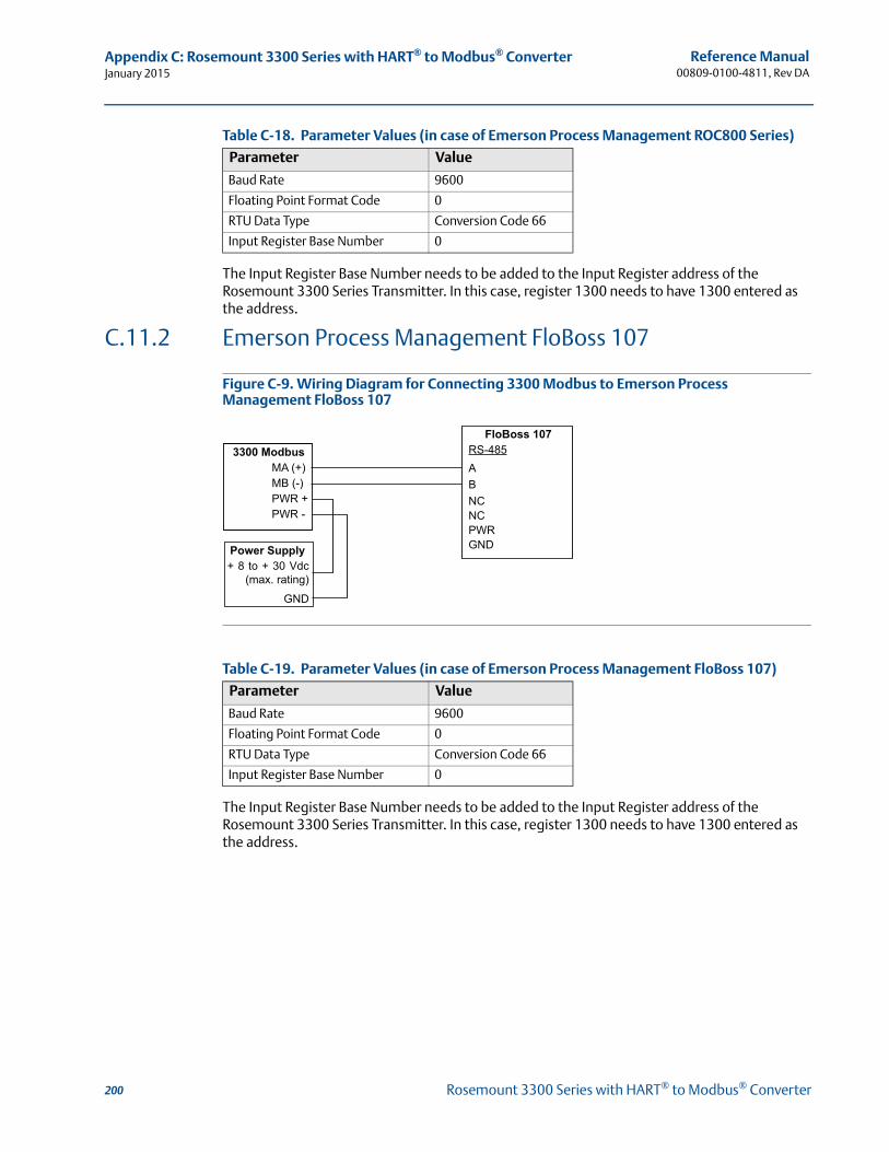
Reference Manual00809-0100-4811, Rev DA
Appendix C: Rosemount 3300 Series with HART® to Modbus® ConverterJanuary 2015
Table C-18. Parameter Values (in case of Emerson Process Management ROC800 Series)
The Input Register Base Number needs to be added to the Input Register address of the Rosemount 3300 Series Transmitter. In this case, register 1300 needs to have 1300 entered as the address.
C.11.2 Emerson Process Management FloBoss 107
Figure C-9. Wiring Diagram for Connecting 3300 Modbus to Emerson Process Management FloBoss 107
Table C-19. Parameter Values (in case of Emerson Process Management FloBoss 107)
The Input Register Base Number needs to be added to the Input Register address of the Rosemount 3300 Series Transmitter. In this case, register 1300 needs to have 1300 entered as the address.
Parameter Value
Baud Rate 9600
Floating Point Format Code 0
RTU Data Type Conversion Code 66
Input Register Base Number 0
Parameter Value
Baud Rate 9600
Floating Point Format Code 0
RTU Data Type Conversion Code 66
Input Register Base Number 0
RS-485ABNCNCPWRGND
MA (+)MB (-)PWR +PWR -
FloBoss 1073300 Modbus
Power Supply+ 8 to + 30 Vdc
(max. rating)GND
200 Rosemount 3300 Series with HART® to Modbus® Converter
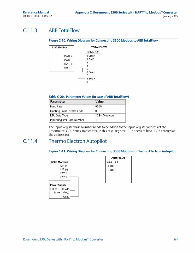
Reference Manual 00809-0100-4811, Rev DA
Appendix C: Rosemount 3300 Series with HART® to Modbus® ConverterJanuary 2015
C.11.3 ABB TotalFlow
Figure C-10. Wiring Diagram for Connecting 3300 Modbus to ABB TotalFlow
Table C-20. Parameter Values (in case of ABB TotalFlow)
The Input Register Base Number needs to be added to the Input Register address of the Rosemount 3300 Series Transmitter. In this case, register 1302 needs to have 1303 entered as the address etc.
C.11.4 Thermo Electron Autopilot
Figure C-11. Wiring Diagram for Connecting 3300 Modbus to Thermo Electron Autopilot
Parameter Value
Baud Rate 9600
Floating Point Format Code 0
RTU Data Type 16 Bit Modicon
Input Register Base Number 1
+ 8 to + 30 Vdc (max. rating)
GND
Power Supply
201Rosemount 3300 Series with HART® to Modbus® Converter
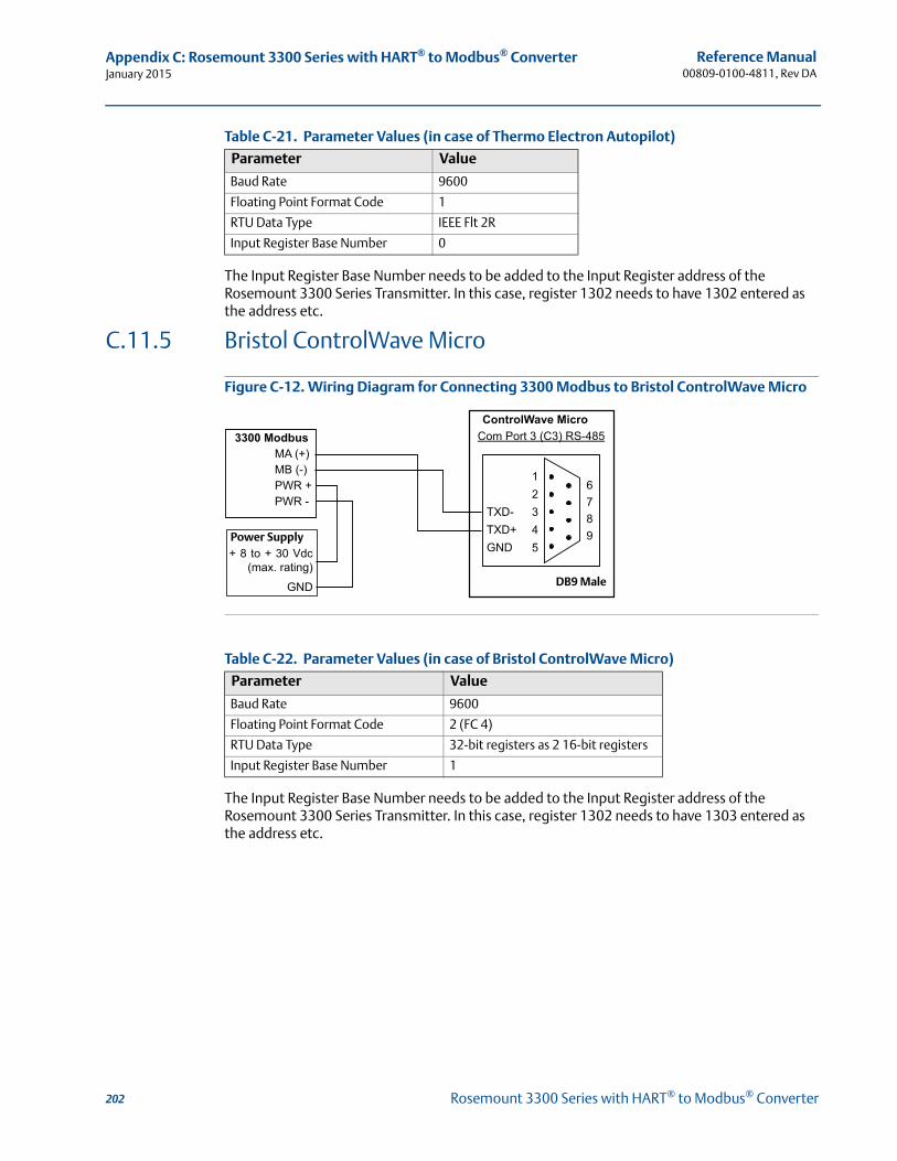
Reference Manual00809-0100-4811, Rev DA
Appendix C: Rosemount 3300 Series with HART® to Modbus® ConverterJanuary 2015
Table C-21. Parameter Values (in case of Thermo Electron Autopilot)
The Input Register Base Number needs to be added to the Input Register address of the Rosemount 3300 Series Transmitter. In this case, register 1302 needs to have 1302 entered as the address etc.
C.11.5 Bristol ControlWave Micro
Figure C-12. Wiring Diagram for Connecting 3300 Modbus to Bristol ControlWave Micro
Table C-22. Parameter Values (in case of Bristol ControlWave Micro)
The Input Register Base Number needs to be added to the Input Register address of the Rosemount 3300 Series Transmitter. In this case, register 1302 needs to have 1303 entered as the address etc.
Parameter Value
Baud Rate 9600
Floating Point Format Code 1
RTU Data Type IEEE Flt 2R
Input Register Base Number 0
Parameter Value
Baud Rate 9600
Floating Point Format Code 2 (FC 4)
RTU Data Type 32-bit registers as 2 16-bit registers
Input Register Base Number 1
+ 8 to + 30 Vdc (max. rating)
GND DB9 Male
Power Supply
202 Rosemount 3300 Series with HART® to Modbus® Converter
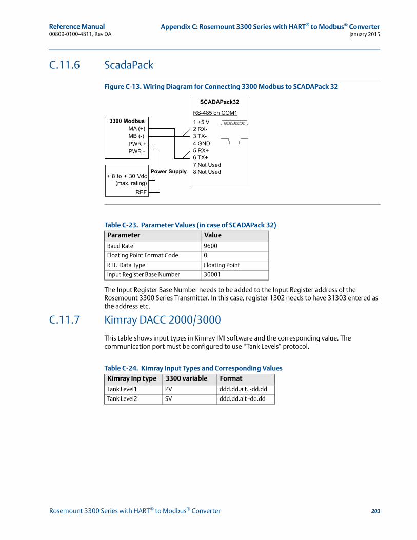
Reference Manual 00809-0100-4811, Rev DA
Appendix C: Rosemount 3300 Series with HART® to Modbus® ConverterJanuary 2015
C.11.6 ScadaPack
Figure C-13. Wiring Diagram for Connecting 3300 Modbus to SCADAPack 32
Table C-23. Parameter Values (in case of SCADAPack 32)
The Input Register Base Number needs to be added to the Input Register address of the Rosemount 3300 Series Transmitter. In this case, register 1302 needs to have 31303 entered as the address etc.
C.11.7 Kimray DACC 2000/3000
This table shows input types in Kimray IMI software and the corresponding value. The communication port must be configured to use “Tank Levels” protocol.
Table C-24. Kimray Input Types and Corresponding Values
Parameter Value
Baud Rate 9600
Floating Point Format Code 0
RTU Data Type Floating Point
Input Register Base Number 30001
Kimray Inp type 3300 variable Format
Tank Level1 PV ddd.dd.alt. -dd.dd
Tank Level2 SV ddd.dd.alt -dd.dd
+ 8 to + 30 Vdc (max. rating)
REF
Power Supply
203Rosemount 3300 Series with HART® to Modbus® Converter

Reference Manual00809-0100-4811, Rev DA
Appendix C: Rosemount 3300 Series with HART® to Modbus® ConverterJanuary 2015
C.12 Troubleshooting
No communication on RS-485 bus (MA (+), MB (-))
Check that the cables are connected
Check that PWR+ is connected to + and PWR- is connected to - on the power supply
Make sure the 3300 transmitter is supplied with 8-30 Vdc (max. rating)
Try alternating MA (+)/MB (-)if you are unsure of the polarity
If an RS-485 converter is used, make sure it is properly installed and configured
The last 3300 transmitter may need a terminating 120-resistor connected between MA (+) and MB (-)
No 3300 communication in RCT
Using HART+, HART-
HART modem is not properly connected
Polling address is incorrect in RCT (default 1)
Using MA (+), MB (-)
See No communication on RS-485 bus
Polling address is incorrect in RCT (default 1)
Cycle the power and wait 20 seconds before polling
No communication with Modbus RTU protocol
See No communication on RS-485 bus
Make sure the “Modbus communication protocol configuration” on page 186 is done properly
Make sure the Modbus RTU address is unique on the bus
Cycle the power and try to connect
Check the RTU communication settings
No communication with Modbus ASCII protocol
See No communication on RS-485 bus
Make sure the “Modbus communication protocol configuration” on page 186 is done properly
Make sure the Modbus ASCII address is unique on the bus
Cycle the power, waiting 40 seconds before communication begins
Check the RTU communication settings
No communication with Levelmaster protocol
See No communication on RS-485 bus
Make sure the “Modbus communication protocol configuration” on page 186 is done properly
Make sure the Levelmaster address is unique on the bus
Cycle the power, waiting 40 seconds before communication begins
Check the RTU communication settings
204 Rosemount 3300 Series with HART® to Modbus® Converter
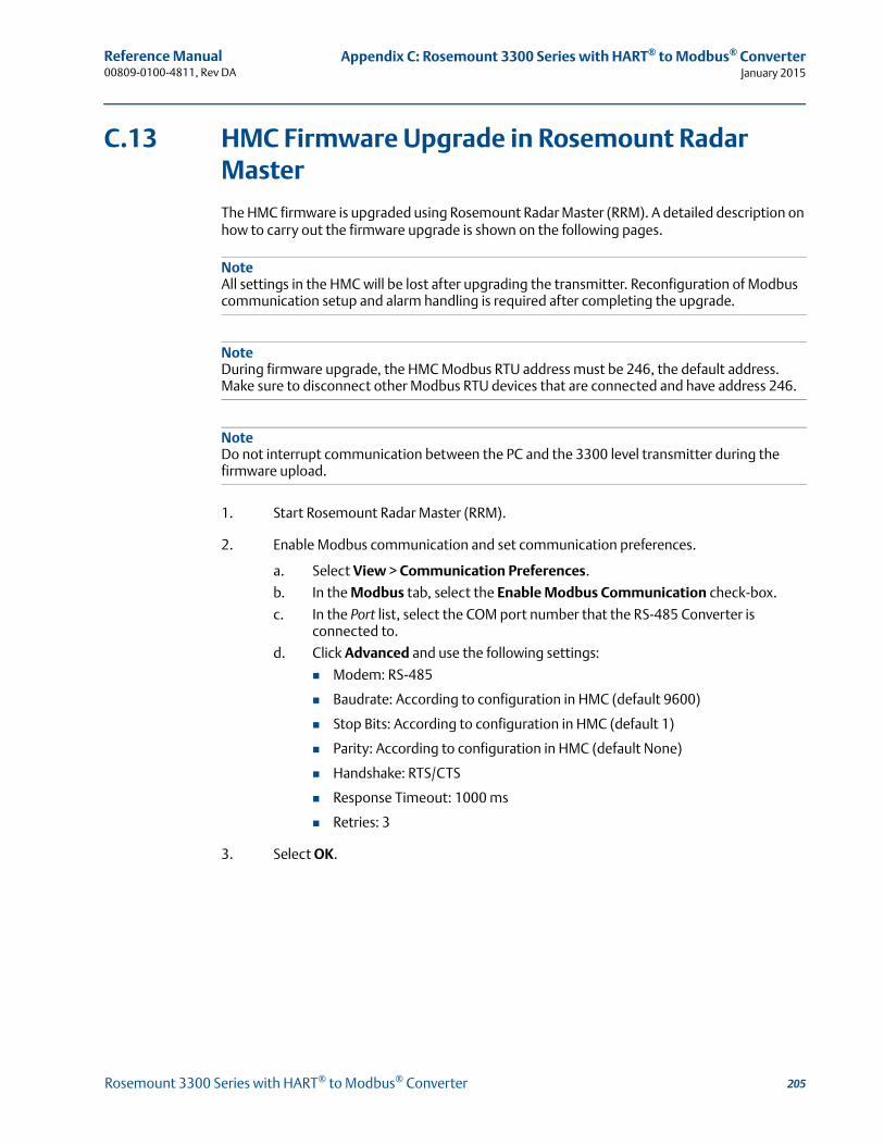
Reference Manual 00809-0100-4811, Rev DA
Appendix C: Rosemount 3300 Series with HART® to Modbus® ConverterJanuary 2015
C.13 HMC Firmware Upgrade in Rosemount Radar Master
The HMC firmware is upgraded using Rosemount Radar Master (RRM). A detailed description on how to carry out the firmware upgrade is shown on the following pages.
NoteAll settings in the HMC will be lost after upgrading the transmitter. Reconfiguration of Modbus communication setup and alarm handling is required after completing the upgrade.
NoteDuring firmware upgrade, the HMC Modbus RTU address must be 246, the default address. Make sure to disconnect other Modbus RTU devices that are connected and have address 246.
NoteDo not interrupt communication between the PC and the 3300 level transmitter during the firmware upload.
1. Start Rosemount Radar Master (RRM).
2. Enable Modbus communication and set communication preferences.
a. Select View > Communication Preferences.
b. In the Modbus tab, select the Enable Modbus Communication check-box.
c. In the Port list, select the COM port number that the RS-485 Converter is connected to.
d. Click Advanced and use the following settings:
Modem: RS-485
Baudrate: According to configuration in HMC (default 9600)
Stop Bits: According to configuration in HMC (default 1)
Parity: According to configuration in HMC (default None)
Handshake: RTS/CTS
Response Timeout: 1000 ms
Retries: 3
3. Select OK.
205Rosemount 3300 Series with HART® to Modbus® Converter
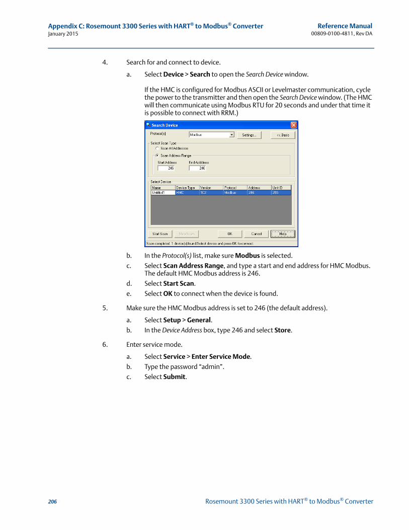
Reference Manual00809-0100-4811, Rev DA
Appendix C: Rosemount 3300 Series with HART® to Modbus® ConverterJanuary 2015
4. Search for and connect to device.
a. Select Device > Search to open the Search Device window.
If the HMC is configured for Modbus ASCII or Levelmaster communication, cycle the power to the transmitter and then open the Search Device window. (The HMC will then communicate using Modbus RTU for 20 seconds and under that time it is possible to connect with RRM.)
b. In the Protocol(s) list, make sure Modbus is selected.
c. Select Scan Address Range, and type a start and end address for HMC Modbus. The default HMC Modbus address is 246.
d. Select Start Scan.
e. Select OK to connect when the device is found.
5. Make sure the HMC Modbus address is set to 246 (the default address).
a. Select Setup > General.
b. In the Device Address box, type 246 and select Store.
6. Enter service mode.
a. Select Service > Enter Service Mode.
b. Type the password “admin”.
c. Select Submit.
206 Rosemount 3300 Series with HART® to Modbus® Converter
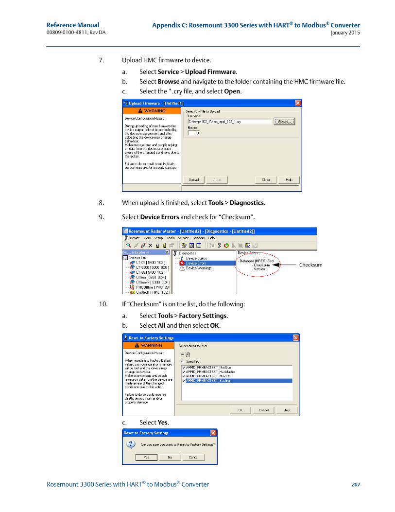
Reference Manual 00809-0100-4811, Rev DA
Appendix C: Rosemount 3300 Series with HART® to Modbus® ConverterJanuary 2015
7. Upload HMC firmware to device.
a. Select Service > Upload Firmware.
b. Select Browse and navigate to the folder containing the HMC firmware file.
c. Select the *.cry file, and select Open.
8. When upload is finished, select Tools > Diagnostics.
9. Select Device Errors and check for “Checksum”.
10. If “Checksum” is on the list, do the following:
a. Select Tools > Factory Settings.
b. Select All and then select OK.
c. Select Yes.
Checksum
207Rosemount 3300 Series with HART® to Modbus® Converter
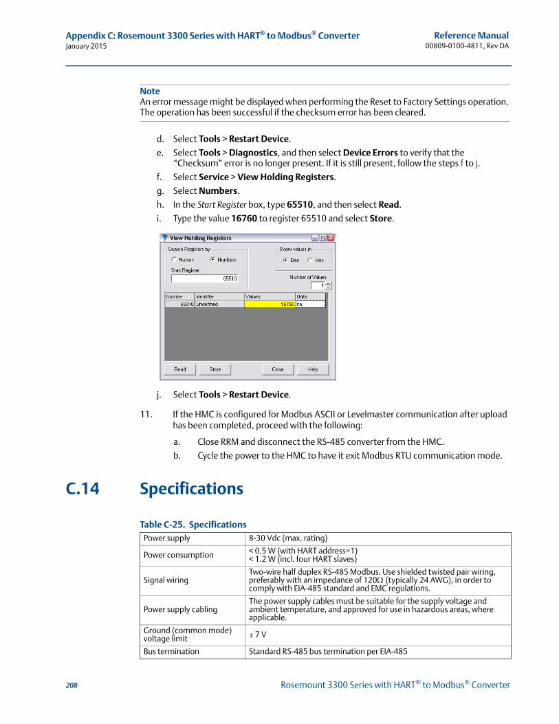
Reference Manual00809-0100-4811, Rev DA
Appendix C: Rosemount 3300 Series with HART® to Modbus® ConverterJanuary 2015
NoteAn error message might be displayed when performing the Reset to Factory Settings operation. The operation has been successful if the checksum error has been cleared.
d. Select Tools > Restart Device.
e. Select Tools > Diagnostics, and then select Device Errors to verify that the “Checksum” error is no longer present. If it is still present, follow the steps f to j.
f. Select Service > View Holding Registers.
g. Select Numbers.
h. In the Start Register box, type 65510, and then select Read.
i. Type the value 16760 to register 65510 and select Store.
j. Select Tools > Restart Device.
11. If the HMC is configured for Modbus ASCII or Levelmaster communication after upload has been completed, proceed with the following:
a. Close RRM and disconnect the RS-485 converter from the HMC.
b. Cycle the power to the HMC to have it exit Modbus RTU communication mode.
C.14 Specifications
Table C-25. Specifications Power supply 8-30 Vdc (max. rating)
Power consumption < 0.5 W (with HART address=1)< 1.2 W (incl. four HART slaves)
Signal wiringTwo-wire half duplex RS-485 Modbus. Use shielded twisted pair wiring, preferably with an impedance of 120(typically 24 AWG), in order to comply with EIA-485 standard and EMC regulations.
Power supply cablingThe power supply cables must be suitable for the supply voltage and ambient temperature, and approved for use in hazardous areas, where applicable.
Ground (common mode)voltage limit ± 7 V
Bus termination Standard RS-485 bus termination per EIA-485
208 Rosemount 3300 Series with HART® to Modbus® Converter

Reference Manual 00809-0100-4811, Rev DA
IndexJanuary 2015
Index
Numerics20 mA point . . . . . . . . . . . . . . . . . . . . . . . . . . . . . . . . . . 64, 734 and 20 mA points . . . . . . . . . . . . . . . . . . . . . . . . . . . . . . . . 734 mA point . . . . . . . . . . . . . . . . . . . . . . . . . . . . . . . . . . . 64, 80751 Field Signal Indicator . . . . . . . . . . . . . . . . . . . . . . . . . . . 60
AAgitators . . . . . . . . . . . . . . . . . . . . . . . . . . . . . . . . . . . . . 13, 28Alarm switch . . . . . . . . . . . . . . . . . . . . . . . . . . . . . . . . . . . . . 21Amplitude threshold settings . . . . . . . . . . . . . . . . . . . . . . 104Amplitude thresholds . . . . . . . . . . . . . . . . . . . . . . . . . . . . . . 95AMS Suite . . . . . . . . . . . . . . . . . . . . . . . . . . . . . . . . . . . . . . . . 10Analog output saturation values . . . . . . . . . . . . . . . . . . . . 20Analog output calibration . . . . . . . . . . . . . . . . . . . . . . . . . 100Anchoring . . . . . . . . . . . . . . . . . . . . . . . . . . . . . . . . . . . . . . . . 36Applications . . . . . . . . . . . . . . . . . . . . . . . . . . . . . . . . . . . . . . . 8Approval drawings . . . . . . . . . . . . . . . . . . . . . . . . . . . . . . . 172
BBridging . . . . . . . . . . . . . . . . . . . . . . . . . . . . . . . . . . . . . . . . . . 11BSP/G threads . . . . . . . . . . . . . . . . . . . . . . . . . . . . . . . . . . . . 31Burst mode . . . . . . . . . . . . . . . . . . . . . . . . . . . . . . . . . . . 87, 89Burst option . . . . . . . . . . . . . . . . . . . . . . . . . . . . . . . . . . . . . . 88
CCable selection . . . . . . . . . . . . . . . . . . . . . . . . . . . . . . . . . . . 53Cable/conduit entries . . . . . . . . . . . . . . . . . . . . . . . . . . . . . . 52Calibration . . . . . . . . . . . . . . . . . . . . . . . . . . . . . . . . . 100, 101Calibration offset . . . . . . . . . . . . . . . . . . . . . . . . . . . . . . . . . . 94Canadian Standards Association
approval . . . . . . . . . . . . . . . . . . . . . . . . . . . . . . . . . . . . 162system control drawing . . . . . . . . . . . . . . . . . . . . . . . 174
Centering disc . . . . . . . . . . . . . . . . . . . . . . . . . . . 24, 49, 139Centering piece . . . . . . . . . . . . . . . . . . . . . . . . . . . . . . . . . . . 35Changing the probe . . . . . . . . . . . . . . . . . . . . . . . . . . . . . . 111Coating . . . . . . . . . . . . . . . . . . . . . . . . . . . . . . . . . . . . . . . . . . 11COM Port . . . . . . . . . . . . . . . . . . . . . . . . . . . . . . . . . . . . . . . . 75COM Port Buffers . . . . . . . . . . . . . . . . . . . . . . . . . . . . . . . . . . 89Configuration . . . . . . . . . . . . . . . . . . . . . . . . . . . . . . . . . . . . . 61
basic . . . . . . . . . . . . . . . . . . . . . . . . . . . . . . . . . . . . . . . . 69volume . . . . . . . . . . . . . . . . . . . . . . . . . . . . . . . . . . 64, 74
Current loop resistance . . . . . . . . . . . . . . . . . . . . . . . . . . . . 53
DDamping . . . . . . . . . . . . . . . . . . . . . . . . . . . . . . . . . . 72, 80, 98Device ID . . . . . . . . . . . . . . . . . . . . . . . . . . . . . . . . . . . . . . . . . 79Device name . . . . . . . . . . . . . . . . . . . . . . . . . . . . . . . . . . . . . 79Device revision . . . . . . . . . . . . . . . . . . . . . . . . . . . . . . . . . . . . 68Device type . . . . . . . . . . . . . . . . . . . . . . . . . . . . . . . . . . . . . . . 79Diagnostic messages . . . . . . . . . . . . . . . . . . . . . . . . 112, 113
Dielectric chart . . . . . . . . . . . . . . . . . . . . . . . . . . . . . . . . . . . 71Dielectric constant
upper product . . . . . . . . . . . . . . . . . . . . . . . . . . . . . . . . 63vapor . . . . . . . . . . . . . . . . . . . . . . . . . . . . . . . . . . . . . . . . 63
Dielectric constant . . . . . . . . . . . . . . . . . . . . . . . . . 12, 71, 83Dielectric constant calculator . . . . . . . . . . . . . . . . . . . . . . . 12Disk logging . . . . . . . . . . . . . . . . . . . . . . . . . . . . . . . . . . . . . . 96Display
alarm . . . . . . . . . . . . . . . . . . . . . . . . . . . . . . . . . . . . . . . . 92write protection . . . . . . . . . . . . . . . . . . . . . . . . . . . . . . 92
Display panel . . . . . . . . . . . . . . . . . . . . . . . . . . . . . . . . . .72, 91Disturbances
Upper Null Zone . . . . . . . . . . . . . . . . . . . . . . . . . . . . . 102
EElectrical installation . . . . . . . . . . . . . . . . . . . . . . . . . . . . . . 52
connecting the transmitter . . . . . . . . . . . . . . . . . . . . 55intrinsically safe output . . . . . . . . . . . . . . . . . . . . . . . . 57non-intrinsically safe output . . . . . . . . . . . . . . . . . . . . 56Tri-Loop . . . . . . . . . . . . . . . . . . . . . . . . . . . . . . . . . .58, 87
Emulsion layers . . . . . . . . . . . . . . . . . . . . . . . . . . . . . . . . . . . 13EPROM ID . . . . . . . . . . . . . . . . . . . . . . . . . . . . . . . . . . . . . . . . 79Errors . . . . . . . . . . . . . . . . . . . . . . . . . . . . . . . . . . . . . . . 92, 113European ATEX Directive Information . . . . . . . . . . . . . . 163
FFactory Mutual
approval . . . . . . . . . . . . . . . . . . . . . . . . . . . . . . . . . . . . 161system control drawing . . . . . . . . . . . . . . . . . . . . . . . 173
Field Communicator . . . . . . . . . . . . . . . . . . . . . . . . . . 67, 106Flange connection . . . . . . . . . . . . . . . . . . . . . . . . . . . . . . . . 23Foam . . . . . . . . . . . . . . . . . . . . . . . . . . . . . . . . . . . . . . . . . . . . 11Free space . . . . . . . . . . . . . . . . . . . . . . . . . . . . . . . . . . . . . . . 26
GGrounding . . . . . . . . . . . . . . . . . . . . . . . . . . . . . . . . . . . . . . . 52
HHardware Rev . . . . . . . . . . . . . . . . . . . . . . . . . . . . . . . . . . . . 79HART communicator . . . . . . . . . . . . . . . . . . . . . . . . . . . . . . 67Hazardous locations certifications . . . . . . . . . . . . . . . . . . 161Heating coils . . . . . . . . . . . . . . . . . . . . . . . . . . . . . . . . . .13, 27High level rates . . . . . . . . . . . . . . . . . . . . . . . . . . . . . . . . . . . 98
IImmersed Probe . . . . . . . . . . . . . . . . . . . . . . . . . . . . . . . . . . 99
Index-1Index
Reference Manual00809-0100-4811, Rev DA
IndexJanuary 2015
Installationcable selection . . . . . . . . . . . . . . . . . . . . . . . . . . . . . . . . 53cable/conduit entries . . . . . . . . . . . . . . . . . . . . . . . . . . 52flange connection . . . . . . . . . . . . . . . . . . . . . . . . . . . . . 23free space . . . . . . . . . . . . . . . . . . . . . . . . . . . . . . . . . . . . 26grounding . . . . . . . . . . . . . . . . . . . . . . . . . . . . . . . . . . . 52mounting considerations . . . . . . . . . . . . . . . . . . . . . . 22mounting position . . . . . . . . . . . . . . . . . . . . . . . . . . . . 27power requirements . . . . . . . . . . . . . . . . . . . . . . . . . . 53procedure . . . . . . . . . . . . . . . . . . . . . . . . . . . . . . . . . . . . 19shortening the probe . . . . . . . . . . . . . . . . . . . . . . . . . . 33still pipes . . . . . . . . . . . . . . . . . . . . . . . . . . . . . . . . . . . . . 24threaded connection . . . . . . . . . . . . . . . . . . . . . . . . . . 22
Installation Wizard . . . . . . . . . . . . . . . . . . . . . . . . . . . . . . . . 76Integral display . . . . . . . . . . . . . . . . . . . . . . . . . . . . . . . . . . . 91Interface . . . . . . . . . . . . . . . . . . . . . . . . . . . . . . . . . . . . . . . . . 12
fully immersed probes . . . . . . . . . . . . . . . . . . . . . . . . . 99low dielectric constants . . . . . . . . . . . . . . . . . . . . . . . . 96
Interface immersed probe . . . . . . . . . . . . . . . . . . . . . . . . . . 72
LLCD . . . . . . . . . . . . . . . . . . . . . . . . . . . . . . . . . . . . . . . . . . . . . . 85Level and distance calibration . . . . . . . . . . . . . . . . . . . . . . 101Logging . . . . . . . . . . . . . . . . . . . . . . . . . . . . . . . . . . . . . 96, 107Loop-powered transmitter. . . . . . . . . . . . . . . . . . . . . . . . . . 10Lower Range Value (LRV) . . . . . . . . . . . . . . . . . . . . . . . . . . . 73Lower transition zone . . . . . . . . . . . . . . . . . . . . . . . . . . . . . . 16
MMaximum load resistance . . . . . . . . . . . . . . . . . . . . . 54, 118Maximum upper product thickness . . . . . . . . . . . . . . 13, 72Measurement mode . . . . . . . . . . . . . . . . . . . . . . . . . . . 71, 82Measurement principle . . . . . . . . . . . . . . . . . . . . . . . . . . . . . 7Measurement units . . . . . . . . . . . . . . . . . . . . . . . . . . . . 70, 79Measuring range . . . . . . . . . . . . . . . . . . . . . . . . . . . . . . . . . . 11Memory map . . . . . . . . . . . . . . . . . . . . . . . . . . . . . . . . . . . .109Mounting position . . . . . . . . . . . . . . . . . . . . . . . . . . . . . . . . 27Multidrop connection . . . . . . . . . . . . . . . . . . . . . . . . . . . . . . 59Multidrop mode . . . . . . . . . . . . . . . . . . . . . . . . . . . . . . . . . . 59
NNAMUR-compliant alarm . . . . . . . . . . . . . . . . . . . . . . . . . . . 20Non-metallic tanks . . . . . . . . . . . . . . . . . . . . . . . . . . . . . . . . 24Nozzle
maximum height . . . . . . . . . . . . . . . . . . . . . . . . . . . . . 23minimum diameter . . . . . . . . . . . . . . . . . . . . . . . . . . . 23
NPT threads . . . . . . . . . . . . . . . . . . . . . . . . . . . . . . . . . . . . . . 31
OOSHA . . . . . . . . . . . . . . . . . . . . . . . . . . . . . . . . . . . . . . . . . . . . . 5
PPipe installations
centering disc . . . . . . . . . . . . . . . . . . . . . . . . . . . . . . . . 49Plate design . . . . . . . . . . . . . . . . . . . . . . . . . . . . . . . . . 30, 124Poll address . . . . . . . . . . . . . . . . . . . . . . . . . . . . . . . . . . . . . . 59Power requirements . . . . . . . . . . . . . . . . . . . . . . . . . . . . . . . 53Power supply . . . . . . . . . . . . . . . . . . . . . . . . . . . . . . . 117, 120Primary Variable (PV) . . . . . . . . . . . . . . . . . . . . . . . . . . . . . . 69Probe
anchoring . . . . . . . . . . . . . . . . . . . . . . . . . . . . . . . . . . . . 36changing . . . . . . . . . . . . . . . . . . . . . . . . . . . . . . . . . . . 111shortening . . . . . . . . . . . . . . . . . . . . . . . . . . . . . . . . . . . 33
Probe angle . . . . . . . . . . . . . . . . . . . . . . . . . . . . . . . . . . .64, 72Probe length . . . . . . . . . . . . . . . . . . . . . . . . . . . . . . 62, 63, 70Probe type . . . . . . . . . . . . . . . . . . . . . . . . . . . . . . . . 14, 63, 70Process connection . . . . . . . . . . . . . . . . . . . . . . . . . . . . . . . . 22Product dielectric . . . . . . . . . . . . . . . . . . . . . . . . . . . . . . . . . 71
RRadar Configuration Tool (RCT) . . . . . . . . . . . . . . . . . .10, 75Range values . . . . . . . . . . . . . . . . . . . . . . . . . . . . . . . . . . . . . 73RCT . . . . . . . . . . . . . . . . . . . . . . . . . . . . . . . . . . . . . . . . . . . . . 75
COM Port . . . . . . . . . . . . . . . . . . . . . . . . . . . . . . . . . . . . 75installing . . . . . . . . . . . . . . . . . . . . . . . . . . . . . . . . . . . . . 75logging . . . . . . . . . . . . . . . . . . . . . . . . . . . . . . . . . . . . . . 96saving the configuration . . . . . . . . . . . . . . . . . . . . . . 108setup . . . . . . . . . . . . . . . . . . . . . . . . . . . . . . . . . . . . . . . . 78waveform plot . . . . . . . . . . . . . . . . . . . . . . . . . . . . . . . . 95Wizard . . . . . . . . . . . . . . . . . . . . . . . . . . . . . . . . . . . . . . 76
Receive buffer . . . . . . . . . . . . . . . . . . . . . . . . . . . . . . . . . . . . 87Recommended mounting position . . . . . . . . . . . . . . . . . . 27Reference gauge height . . . . . . . . . . . . . . . . 62, 63, 70, 94RHCS Server . . . . . . . . . . . . . . . . . . . . . . . . . . . . . . . . . . . . . . 76Rosemount 751 Field Signal Indicator . . . . . . . . . . . . . . . . 10
SSave Setup . . . . . . . . . . . . . . . . . . . . . . . . . . . . . . . . . . . . . . 108Set poll address . . . . . . . . . . . . . . . . . . . . . . . . . . . . . . . . . . . 59Setup
Basics . . . . . . . . . . . . . . . . . . . . . . . . . . . . . . . . . . . . . . . 79LCD . . . . . . . . . . . . . . . . . . . . . . . . . . . . . . . . . . . . . . . . . 85Output . . . . . . . . . . . . . . . . . . . . . . . . . . . . . . . . . . . . . . 80Save configuration . . . . . . . . . . . . . . . . . . . . . . . . . . . 108Tank Config . . . . . . . . . . . . . . . . . . . . . . . . . . . . . . . . . . 81Volume . . . . . . . . . . . . . . . . . . . . . . . . . . . . . . . . . . . . . . 84
Software Rev . . . . . . . . . . . . . . . . . . . . . . . . . . . . . . . . . . . . . 79Spacers . . . . . . . . . . . . . . . . . . . . . . . . . . . . . . . . . . . . . . .34, 35Standard tank shapes . . . . . . . . . . . . . . . . . . . . . . . . . . . . . . 66Strapping table . . . . . . . . . . . . . . . . . . . . . . . . . . . . . . . .65, 74System architecture . . . . . . . . . . . . . . . . . . . . . . . . . . . . . . . 10
TTank connection . . . . . . . . . . . . . . . . . . . . . . . . . . . . . . .29, 30
flange . . . . . . . . . . . . . . . . . . . . . . . . . . . . . . . . . . . . . . . 29threaded . . . . . . . . . . . . . . . . . . . . . . . . . . . . . . . . . . . . . 31
Index-2 Index
Reference Manual 00809-0100-4811, Rev DA
IndexJanuary 2015
Tank dimensions . . . . . . . . . . . . . . . . . . . . . . . . . . . . . . . . . . 74Tank geometry . . . . . . . . . . . . . . . . . . . . . . . . . . . . . . . 62, 94Tank shape . . . . . . . . . . . . . . . . . . . . . . . . . . . . . . . . . . . 14, 66Tank type . . . . . . . . . . . . . . . . . . . . . . . . . . . . . . . . . . . . 64, 74Threaded connection . . . . . . . . . . . . . . . . . . . . . . . . . . . . . . 22Threshold settings . . . . . . . . . . . . . . . . . . . . . . . . . . . . . . . . 97Time Domain Reflectometry (TDR) . . . . . . . . . . . . . . . . . . . 7Transfer buffer . . . . . . . . . . . . . . . . . . . . . . . . . . . . . . . . . . . . 89Transition zones . . . . . . . . . . . . . . . . . . . . . . . . . . . . . . . . . . 16Transmitter head removing . . . . . . . . . . . . . . . . . . . . . . . 110Transmitter housing . . . . . . . . . . . . . . . . . . . . . . . . . . . . . . . 14Transmitter reference point . . . . . . . . . . . . . . . . . . . . . . . . 94Transmitter variables . . . . . . . . . . . . . . . . . . . . . . . . . . 69, 74Tri-Loop . . . . . . . . . . . . . . . . . . . . . . . . . . . . . . . . . . . . . . 58, 87Trim Near Zone . . . . . . . . . . . . . . . . . . . . . . . . . . . . . . . . . . 102Troubleshooting . . . . . . . . . . . . . . . . . . . . . . . . . . . . . . . . . . 93Turbulent conditions . . . . . . . . . . . . . . . . . . . . . . . . . . . . . . 28
UUpper Null Zone (UNZ) . . . . . . . . . . . . 23, 64, 82, 102, 103Upper Range Value (URV). . . . . . . . . . . . . . . . . . . . . . . 73, 80Upper reference point . . . . . . . . . . . . . . . . . . . . . . 16, 62, 94Upper Transition Zone . . . . . . . . . . . . . . . . . . . . . . . . . 16, 73
VVapor . . . . . . . . . . . . . . . . . . . . . . . . . . . . . . . . . . . . . . . . . . . . 11Vapor dielectric . . . . . . . . . . . . . . . . . . . . . . . . . . . . . . . . . . . 71Vessel characteristics . . . . . . . . . . . . . . . . . . . . . . . . . . . . . . 13Volume configuration . . . . . . . . . . . . . . . . . . . . . . . . . 64, 74Volume units . . . . . . . . . . . . . . . . . . . . . . . . . . . . . . . . . . . . . 74
WWarnings . . . . . . . . . . . . . . . . . . . . . . . . . . . . . . . . . . . . . . . . 114Waveform plot . . . . . . . . . . . . . . . . . . . . . . . . . . . . . . . . . . . . 95Write protect switch . . . . . . . . . . . . . . . . . . . . . . . . . . . . . . . 21Write protection . . . . . . . . . . . . . . . . . . . . . . . . . . . . . . 20, 92
Index-3Index

Index-4
Reference Manual00809-0100-4811, Rev DA
IndexJanuary 2015
Index


Reference Manual00809-0100-4811, Rev DA
January 2015
Standard Terms and Conditions of Sale can be found at www.rosemount.com/terms_of_sale.The Emerson logo is a trademark and service mark of Emerson Electric Co.AMS, Rosemount, and the Rosemount logotype are registered trademarks of Rosemount Inc.DeltaV, THUM, Tri-Clamp, and Tri-Loop are trademarks of Rosemount Inc.HART and WirelessHART are registered trademarks of the HART Communication Foundation.Modbus is a registered trademark of Modicon, Inc.Viton and Kalrez are registered trademarks of DuPont Performance Elastomers.Microsoft is a registered trademark of Microsoft Corporation in the United States and other countries.Windows is a trademark of Microsoft Corporation in the United States and other countries.FDT is a registered trademark of the FDT group.DTM is a trademark of the FDT group.PACTware is a trademark of PACTware Consortium.NACE is a registered trademark of NACE International.Bristol, ControlWave, and FloBoss are trademarks of Remote Automation Solutions, a subsidiary of Emerson Process Management.E+H FieldCare is a trademark of Endress + Hauser AG.All other marks are the property of their respective owners.
© January 2015 Rosemount, Inc. All rights reserved.
Emerson Process ManagementBlegistrasse 23P.O. Box 1046CH 6341 BaarSwitzerlandTel +41 (0) 41 768 6111Fax +41 (0) 41 768 6300
Emerson Process Management Latin America1300 Concord Terrace, Suite 400Sunrise, Florida 33323 USATel +1 954 846 5030
Emerson FZEP.O. Box 17033Jebel Ali Free ZoneDubai UAETel +971 4 811 8100Fax +971 4 886 5465
Emerson Process ManagementRosemount Measurement8200 Market BoulevardChanhassen, MN 55317 USATel (USA) 1 800 999 9307Tel (International) +1 952 906 8888Fax +1 952 906 8889
Emerson Beijing Instrument CoNo.6 North Street, HepingliDongcheng District, Beijing100013ChinaTel +8610 64282233Fax +8610 642 87640
Emerson Process Management Asia Pacific Pte Ltd1 Pandan CrescentSingapore 128461Tel +65 6777 8211Fax +65 6777 0947Service Support Hotline: +65 6770 8711Email: [email protected]