rosemount 3300 level transmitter - emerson · make sure the main power to the rosemount 3300 ......
TRANSCRIPT
Quick Start Guide00825-0100-4811, Rev JB
May 2017
Rosemount™ 3300 Level Transmitter
Guided Wave Radar
May 2017Quick Start Guide
1.0 About this guideThis start guide provides basic guidelines for the Rosemount 3300 Level Transmitter. Refer to Rosemount 3300 Level Transmitter Reference Manual for more instructions. The manual and this Quick Start Guide (QSG) are also available electronically on Emerson.com/Rosemount.
Any substitution of non-authorized parts or repair, other than exchanging the complete transmitter head or probe assembly, may jeopardize safety and is prohibited.
Unauthorized changes to the product are strictly prohibited as they may unintentionally and unpredictably alter performance and jeopardize safety. Unauthorized changes that interfere with the integrity of the welds or flanges, such as making additional perforations, compromise product integrity and safety. Equipment ratings and certifications are no longer valid on any products that have been damaged or modified without the prior written permission of Emerson™ Automation Solutions. Any continued use of product that has been damaged or modified without prior written authorization is at the customer's sole risk and expense.
Failure to follow safe installation and service guidelines could result in death or serious injury.
Make sure only qualified personnel perform installation or service.
Use the equipment only as specified in this QSG and the Reference Manual. Failure to do so may impair the protection provided by the equipment.
Do not perform any services other than those contained in this manual unless you are qualified.
Flamepath joints are not for repair. Contact the manufacturer.
Explosions could result in death or serious injury.
Verify that the operating environment of the transmitter is consistent with the appropriate hazardous locations specifications. See Product Certifications on page 20 in this Quick Start Guide.
In an Explosion-proof/Flameproof installation, do not remove the transmitter covers when power is applied to the unit.
Before connecting a HART®-based Communicator in an explosive atmosphere, make sure the instruments in the loop are installed in accordance with intrinsically safe or non-incendive field wiring practices.
To avoid process leaks, only use o-rings designed to seal with the corresponding flange adapter.
Electrical shock can result in death or serious injury.
Avoid contact with the leads and terminals. High voltage that may be present on leads can cause electrical shock.
Make sure the main power to the Rosemount 3300 Level Transmitter is off and the lines to any other external power source are disconnected or not powered while wiring the transmitter.
Temperature restrictions apply for Explosion-proof versions. For limits, see certificate-specific information in the Product Certification chapter in this document.
Contents Mount the transmitter head/probe . . . . . . . . . . . . . . . . . . . . . . . . . . . . . . . . . . . . . . . . . . . . . . . . page 4Set jumpers and switches . . . . . . . . . . . . . . . . . . . . . . . . . . . . . . . . . . . . . . . . . . . . . . . . . . . . . . . . page 10Connect the wiring . . . . . . . . . . . . . . . . . . . . . . . . . . . . . . . . . . . . . . . . . . . . . . . . . . . . . . . . . . . . . page 11Configure . . . . . . . . . . . . . . . . . . . . . . . . . . . . . . . . . . . . . . . . . . . . . . . . . . . . . . . . . . . . . . . . . . . . . page 15Environmental conditions . . . . . . . . . . . . . . . . . . . . . . . . . . . . . . . . . . . . . . . . . . . . . . . . . . . . . . . page 19Product certifications . . . . . . . . . . . . . . . . . . . . . . . . . . . . . . . . . . . . . . . . . . . . . . . . . . . . . . . . . . . page 20
2

Quick Start GuideMay 2017
The electronics enclosures are category 2G or 2D equipment. The probes not covered with plastic and not made of titanium, are category 1G or 1D. The plastic covered probes or probes made of titanium, are only category 1G equipment.
Probes with non-conducting surfaces and light metals.
Probes covered with plastic and/or with plastic discs may generate an ignition- capable level of electrostatic charge under certain extreme conditions. Therefore, when the probe is used in a potentially explosive atmosphere, appropriate measures must be taken to prevent electrostatic discharge. These probes are not allowed in dust classified areas.The following probes do not contain plastic or PTFE material, and are allowed to be placed in a Dust classified area:
The Material of Construction Code in the above table can be found in the following position in the Rosemount 3300 Level Transmitter model code: 330xxxxxN...
Probes and flanges containing >7.5% Magnesium or Zirconium are not allowed in explosive dust atmosphere. Please contact Rosemount Tank Radar for additional information.
Probes and flanges containing light metals.
When used in category 1/2G installations, probes and flanges containing Titanium or Zirconium must be mounted in such a way that sparks from impact or friction between these parts and steel cannot occur.
Code Material of construction: Process connection/Probe
1 316L SST (EN 1.4404)
2 Alloy C-276 (UNS N10276) plate design if flanged version
3 Alloy 400 (UNS N04400) plate design if flanged version
5 Titanium Gr-1 and Gr-2
9 Duplex 2205 (plate design if flanged version)
L Alloy 625 (UNS N06625)
M Alloy 400 (UNS N04400), flange design
H Alloy C-276 (UNS N10276)
D Duplex process connection
Category 2G or 2D Category 2G or 2D
Category 1G or 1DProbes according to table 1
Category 1GAll probes possible
ApplicableMarking:
II 1/2 G Ex db [ia Ga] IIC T6…T1 Ga/GbII 1/2 D Ex tb [ia Da] IIIC T85 °C…T450 °C Da/Db
II 1/2 G Ex db [ia Ga] IIC T6…T1 Ga/GbII 2 D Ex tb IIIC T85 °C…T135 °C Db
3
May 2017Quick Start Guide
2.0 Mount the transmitter head/probe
2.1 Tank connection with flange
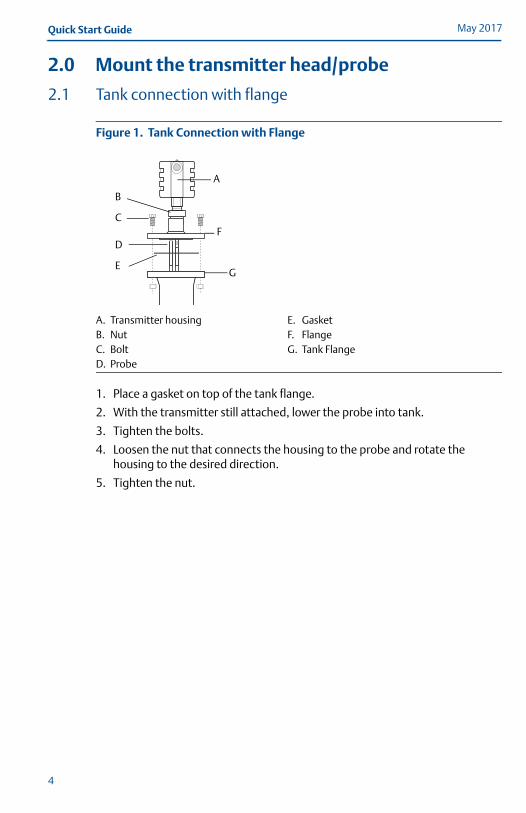
Figure 1. Tank Connection with Flange
1. Place a gasket on top of the tank flange.
2. With the transmitter still attached, lower the probe into tank.
3. Tighten the bolts.
4. Loosen the nut that connects the housing to the probe and rotate the housing to the desired direction.
5. Tighten the nut.
A. Transmitter housing E. GasketB. Nut F. FlangeC. Bolt G. Tank FlangeD. Probe
FD
EG
A
B
C
4
Quick Start GuideMay 2017
2.2 Threaded tank connection
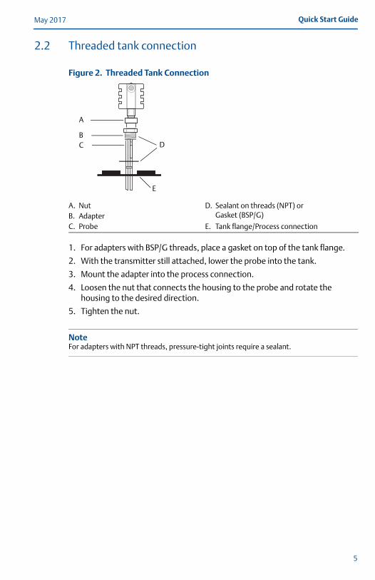
Figure 2. Threaded Tank Connection
1. For adapters with BSP/G threads, place a gasket on top of the tank flange.
2. With the transmitter still attached, lower the probe into the tank.
3. Mount the adapter into the process connection.
4. Loosen the nut that connects the housing to the probe and rotate the housing to the desired direction.
5. Tighten the nut.
NoteFor adapters with NPT threads, pressure-tight joints require a sealant.
A. Nut D. Sealant on threads (NPT) or Gasket (BSP/G)B. Adapter
C. Probe E. Tank flange/Process connection
BC
E
A
D
5
May 2017Quick Start Guide
2.3 Tri Clamp tank connection
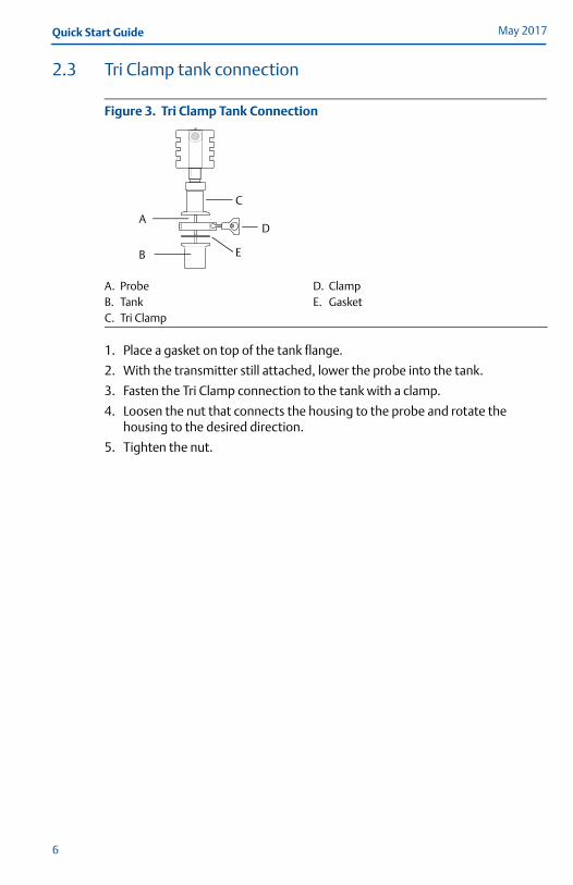
Figure 3. Tri Clamp Tank Connection
1. Place a gasket on top of the tank flange.
2. With the transmitter still attached, lower the probe into the tank.
3. Fasten the Tri Clamp connection to the tank with a clamp.
4. Loosen the nut that connects the housing to the probe and rotate the housing to the desired direction.
5. Tighten the nut.
A. Probe D. ClampB. Tank E. GasketC. Tri Clamp
A
B
C
D
E
6

Quick Start GuideMay 2017
2.4 Bracket mounting
1. Mount the bracket to the wall/pipe with screws suitable for the purpose.
On pipe
On wall
Use screws suitable for the purpose.
2. Mount the transmitter with probe to the bracket and secure with the three supplied screws.
4X
Horizontal pipe
Vertical pipe
4X
3X
7
May 2017Quick Start Guide
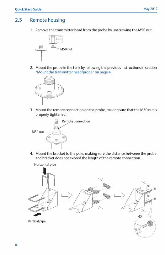
2.5 Remote housing
1. Remove the transmitter head from the probe by unscrewing the M50 nut.
2. Mount the probe in the tank by following the previous instructions in section “Mount the transmitter head/probe” on page 4.
3. Mount the remote connection on the probe, making sure that the M50 nut is properly tightened.
4. Mount the bracket to the pole, making sure the distance between the probe and bracket does not exceed the length of the remote connection.
M50 nut
M50 nut
Remote connection
4X
Horizontal pipe
Vertical pipe
8
Quick Start GuideMay 2017
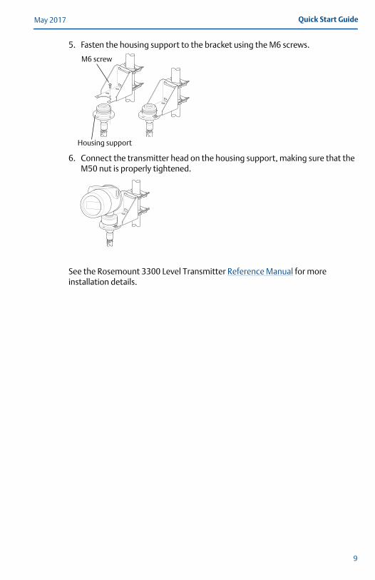
5. Fasten the housing support to the bracket using the M6 screws.
6. Connect the transmitter head on the housing support, making sure that the M50 nut is properly tightened.
See the Rosemount 3300 Level Transmitter Reference Manual for more installation details.
M6 screw
Housing support
9

May 2017Quick Start Guide
3.0 Set jumpers and switchesIf alarm and security jumpers are not set, the transmitter operates with the default alarm condition HIGH and Security OFF. Write Protection must be set after configuration (“Configure” on page 15).
To set Alarm and Write Protection on the circuit board:
1. Remove the cover on the circuit side (see label marked circuit side).
2. To set the 4-20 mA alarm output to LOW, move the alarm switch to the LOW position.
3. To enable the security write protection feature, move the write protect switch to the ON position.
4. Replace the cover and tighten securely.
To set Alarm and Write Protection on the LCD display:
To have the LCD display override the circuit board settings, the write protection switch needs to be in the OFF position and the alarm switch needs to be in the HIGH position.
1. To set the 4-20 mA alarm output to LOW, place jumper between the right and center hole position.
2. To enable the security write protection feature, place jumper between the left and center hole position - ON.
10
Quick Start GuideMay 2017
4.0 Connect the wiringFor HART, the input voltage is 11-42 V (11-30 V in IS applications, 16-42 V in Explosion-proof / Flameproof applications). For Modbus®, the input voltage is 8-30 V.
The transmitter requires shielded twisted pair wiring (18-12 AWG) suitable for the supply voltage and, if applicable, approved for use in hazardous areas.
4.1 Cable/conduit entriesThe electronics housing has two entries for ½ - 14 NPT. Optional M20×1.5 and PG 13.5 adapters are also available. The connections are made in accordance with local or plant electrical codes.
Make sure that unused ports are properly sealed to prevent moisture or other contamination from entering the terminal block compartment of the electronics housing.
NoteRemove any orange caps that may be attached. Use the enclosed metal plug to seal the unused port.
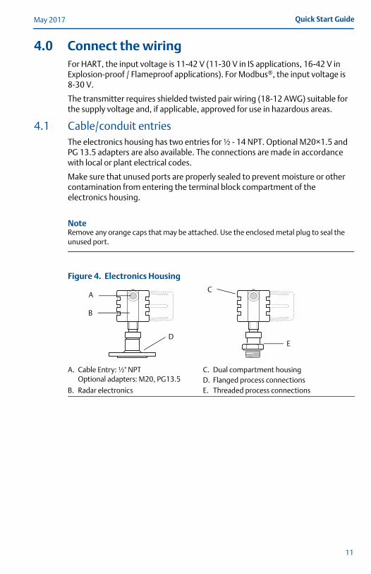
Figure 4. Electronics Housing
A. Cable Entry: ½" NPTOptional adapters: M20, PG13.5
C. Dual compartment housingD. Flanged process connections
B. Radar electronics E. Threaded process connections
B
CA
ED
11

May 2017Quick Start Guide
4.2 Connect the transmitter
1. Make sure the housing is grounded according to Hazardous Locations Certifications, national and local electrical codes.
2. Verify that the power supply is disconnected.
3. Remove the cover on the terminal side (see label marked field terminals).
4. Pull the cable(s) through the cable gland/conduit. For Explosion-proof / Flameproof installations, only use cable glands or conduit entry devices certified Explosion-proof or Flameproof (Ex d llC (gas) or Ex t lllC (dust)).
5. To connect the wires see the illustrations below.
6. If applicable, use the enclosed metal plug to seal any unused port.
7. Replace the cover and tighten.
8. Tighten the cable gland.
9. Connect the power supply.
4.3 Non-Intrinsically Safe HART Output and Type n Approvals: Non-Sparking/ Energy Limited Power Supply
Figure 5. Wiring Diagram
NoteRosemount 3300 Level Transmitters with Flameproof/Explosion-proof HART Output have a built-in barrier; no external barrier needed.
A. Rosemount 3300 Level Transmitter E. HART modemB. Field Communicator F. PCC. Load Resistance 250 G. Maximum voltage: Um=250 VD. Power supply H. HART: Un=42.4 V
D
E
B
F
A G
H
C
12
Quick Start GuideMay 2017
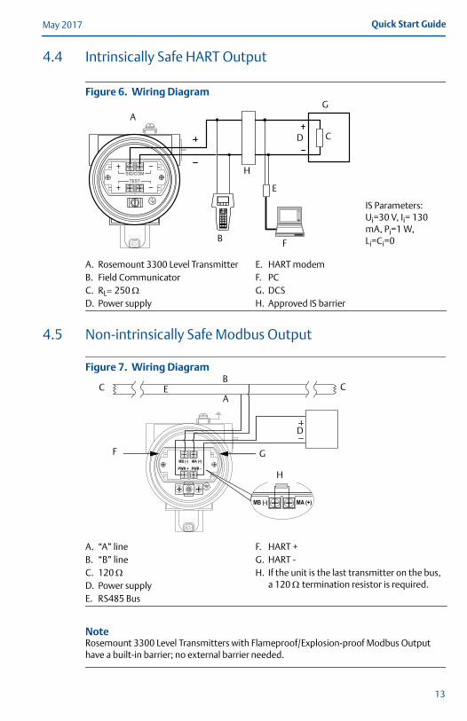
4.4 Intrinsically Safe HART Output
Figure 6. Wiring Diagram
4.5 Non-intrinsically Safe Modbus Output
Figure 7. Wiring Diagram
NoteRosemount 3300 Level Transmitters with Flameproof/Explosion-proof Modbus Output have a built-in barrier; no external barrier needed.
A. Rosemount 3300 Level Transmitter E. HART modemB. Field Communicator F. PCC. RL250 G. DCSD. Power supply H. Approved IS barrier
A. “A” line F. HART +B. “B” line G. HART -C. 120 H. If the unit is the last transmitter on the bus,
a 120 termination resistor is required.D. Power supplyE. RS485 Bus
D
H
G
F
A
IS Parameters:Ui=30 V, Ii= 130 mA, Pi=1 W, Li=Ci=0
E
B
C
D
B
AE
F G
C C
H
13
May 2017Quick Start Guide
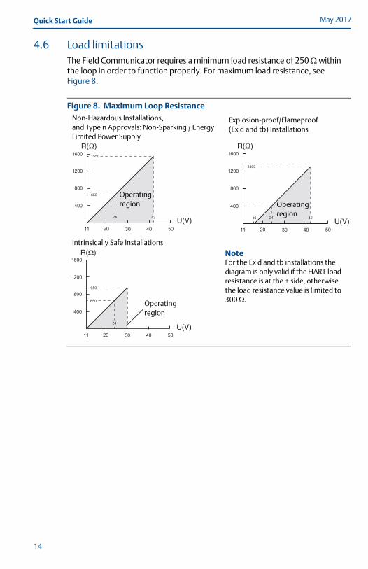
4.6 Load limitationsThe Field Communicator requires a minimum load resistance of 250 within the loop in order to function properly. For maximum load resistance, see Figure 8.
Figure 8. Maximum Loop Resistance
Explosion-proof/Flameproof (Ex d and tb) Installations
Intrinsically Safe Installations
NoteFor the Ex d and tb installations the diagram is only valid if the HART load resistance is at the + side, otherwise the load resistance value is limited to 300 .
Operating region Operating
region
Operating region
Non-Hazardous Installations, and Type n Approvals: Non-Sparking / Energy Limited Power Supply
14

Quick Start GuideMay 2017
5.0 ConfigureIf the transmitter is pre-configured at the factory, this section is only necessary to change or verify the settings.
Configuration of the Rosemount 3300 Level Transmitter can be done either with a Field Communicator, the AMS Device Manager, or Radar Configuration Tools (RCT). If using the Radar Configuration Tools, a HART modem is required, and the procedure is described below, together with the corresponding Field Communicator Fast Key sequence.
5.1 Installing the Radar Configuration Tools (RCT) softwareTo install the RCT software:
1. Insert the installation CD into your CD-ROM drive.
2. Follow the instructions. If the installation program does not automatically start, run Setup.exe from the CD.
5.2 Starting RCTSelect Programs > Rosemount > RCT, and the following window appears(1)
The Help function of the RCT can be reached from the menu or by pressing the F1 key.
1. For optimum performance set COM Port Buffers to 1. You might receive a pop-up reminder of this before the RCT window appears. See Chapter 4 “Start-up” in the Rosemount 3300 Level Transmitter Reference Manual.
Wizard
Setup
15
May 2017Quick Start Guide
Configuration of a Rosemount 3300 Level Transmitter can be done using the installation Wizard for detailed guidance. If you are already familiar with the configuration procedure, or if you want to change settings, you may use the setup function.
5.3 Configuration using the Wizard
1. Make sure that the Tools Bar is open (Project Bar is ticked within View). Then select the Wizard icon or select the View>Wizard menu option.
2. Select the Start button and follow the instructions.
5.4 Configuration using the Setup Function & Fast Key Code
1. Make sure that the Tools Bar is open (Project Bar is ticked within View). Then select the Setup icon or select the View>Setup menu option.
2. Select the appropriate tab: Info (information about the device), Basics (page 16), Output (page 17), Tank Config (page 18), Volume (specification of tank geometry for volume calculations), LCD (display panel settings), or Signal Quality Metrics (for activating/de-activating and display of signal quality metrics, available with the DA1 option).
3. Press the Receive Page button to load the parameters configured in the transmitter into the dialog window. Press the Send Page button to load any parameter changes back to the transmitter.
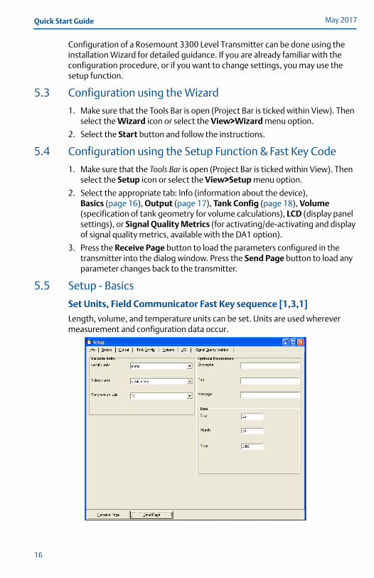
5.5 Setup - Basics
Set Units, Field Communicator Fast Key sequence [1,3,1]
Length, volume, and temperature units can be set. Units are used wherever measurement and configuration data occur.
16

Quick Start GuideMay 2017
5.6 Setup - Output
Set Range Values, Field Communicator Fast Key sequence [1,3,4,3]
The Lower Range value = 4 mA value.
The Upper Range value = 20 mA value.
The 4-20 mA range must not include the upper or lower Transition Zone.(1)
Set Variable Assignment, Field Communicator Fast Key sequence [1,1,1]
Rosemount 3301 available measuring parameters: Level, Distance to Level, Total Volume. For fully immersed probe: Interface Level and Interface Distance.
Rosemount 3302 available measuring parameters: Level, Distance to level, Total Volume, Interface Level, Interface Distance, and Upper Product Layer Thickness.
In the Primary Variable field, the measuring parameter is entered for the analog signal.
More variables can be assigned if the superimposed digital HART signal or a HART Tri-loop™ is used.
Setup - Modbus Communication Parameters
If the transmitter has the Modbus option, configuration of the communication parameters can be set.
1. See the Rosemount 3300 Level Transmitter Reference Manual.
17
May 2017Quick Start Guide
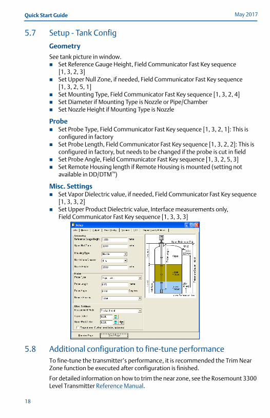
5.7 Setup - Tank Config
Geometry
See tank picture in window. Set Reference Gauge Height, Field Communicator Fast Key sequence
[1, 3, 2, 3] Set Upper Null Zone, if needed, Field Communicator Fast Key sequence
[1, 3, 2, 5, 1] Set Mounting Type, Field Communicator Fast Key sequence [1, 3, 2, 4] Set Diameter if Mounting Type is Nozzle or Pipe/Chamber Set Nozzle Height if Mounting Type is Nozzle
Probe Set Probe Type, Field Communicator Fast Key sequence [1, 3, 2, 1]: This is
configured in factory Set Probe Length, Field Communicator Fast Key sequence [1, 3, 2, 2]: This is
configured in factory, but needs to be changed if the probe is cut in field Set Probe Angle, Field Communicator Fast Key sequence [1, 3, 2, 5, 3] Set Remote Housing length if Remote Housing is mounted (setting not
available in DD/DTM™)
Misc. Settings Set Vapor Dielectric value, if needed, Field Communicator Fast Key sequence
[1, 3, 3, 2] Set Upper Product Dielectric value, Interface measurements only,
Field Communicator Fast Key sequence [1, 3, 3, 3]
5.8 Additional configuration to fine-tune performanceTo fine-tune the transmitter’s performance, it is recommended the Trim Near Zone function be executed after configuration is finished.
For detailed information on how to trim the near zone, see the Rosemount 3300 Level Transmitter Reference Manual.
18
Quick Start GuideMay 2017
6.0 Environmental conditions
6.1 Ambient temperature limits (for use in explosive atmospheres)Explosion-proof/Flame-proof version: -58 °F (-50 °C) Ta +167 °F (+75 °C)
Intrinsically safe version: -58 °F (-50 °C) Ta +158 °F (+70 °C)
National deviations may apply, see Product certifications on page 20.
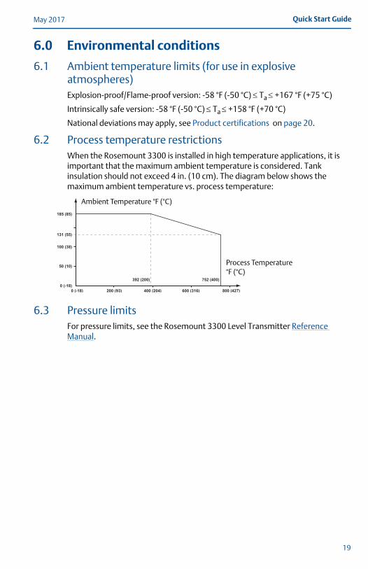
6.2 Process temperature restrictionsWhen the Rosemount 3300 is installed in high temperature applications, it is important that the maximum ambient temperature is considered. Tank insulation should not exceed 4 in. (10 cm). The diagram below shows the maximum ambient temperature vs. process temperature:
6.3 Pressure limitsFor pressure limits, see the Rosemount 3300 Level Transmitter Reference Manual.
Ambient Temperature °F (°C)
Process Temperature °F (°C)
19
May 2017Quick Start Guide
7.0 Product certificationsRev 3.2
7.1 European Directive InformationA copy of the EU Declaration of Conformity can be found at the end of the Quick Start Guide. The most recent revision of the EU Declaration of Conformity can be found at Emerson.com/Rosemount.
7.2 Ordinary Location CertificationAs standard, the transmitter has been examined and tested to determine that the design meets the basic electrical, mechanical, and fire protection requirements by a nationally recognized test laboratory (NRTL) as accredited by the Federal Occupational Safety and Health Administration (OSHA).
7.3 Installing Equipment in North AmericaThe US National Electrical Code (NEC®) and the Canadian Electrical Code (CEC) permit the use of Division marked equipment in Zones and Zone marked equipment in Divisions. The markings must be suitable for the area classification, gas, and temperature class. This information is clearly defined in the respective codes.
7.4 USAE5 Explosionproof (XP), Dust-Ignitionproof (DIP)
Certificate: FM 3013394Standards: FM Class 3600 – 2011; FM Class 3610 – 2010; FM Class 3611 – 2004;
FM Class 3615 – 2006; FM Class 3810 – 2005; ANSI/ISA 60079-0 – 2009;ANSI/ISA 60079-11 – 2009; ANSI/NEMA 250 – 1991; ANSI/IEC 60529 – 2004;
Markings: XP CL I, DIV 1, GP B, C, D; DIP CLII/III, DIV 1, GP E, F, G; T5 Ta=85°C; Type 4X/IP66
Specific Conditions for Safe Use (X):1. Potential Electrostatic Charging Hazard – The enclosure contains non-metallic
material. To prevent the risk for electrostatic sparking the plastic surface should only be cleaned with a damp cloth.
2. WARNING – The apparatus enclosure contains aluminum and is considered to constitute a potential risk of ignition by impact or friction. Care must be taken into account during installation and use to prevent impact or friction.
I5 Intrinsic Safety (IS), Nonincendive (NI)Certificate: FM 3013394Standards: FM Class 3600 – 2011; FM Class 3610 – 2010; FM Class 3611 – 2004;
FM Class 3615 – 2006; FM Class 3810 – 2005; ANSI/ISA 60079-0 – 2009;ANSI/ISA 60079-11 – 2009; ANSI/NEMA 250 – 1991; ANSI/IEC 60529 – 2004;
Markings: IS CL I, DIV 1, GP A, B, C, D, E, F, G in accordance with control drawing 9150077-944; IS (Entity) CL I, Zone 0, AEx IA IIC T4 in accordance with control drawing 9150077-944, NI CL I, DIV 2, GP A, B, C, D, T4a Ta=70 °C; Suitable for use in CL II/III DIV 2, GP A, B, C, D, T4a Ta=70 °C; Type 4X/IP66
20
Quick Start GuideMay 2017
Specific Conditions for Safe Use (X):1. Potential Electrostatic Charging Hazard – The enclosure contains non-metallic
material. To prevent the risk for electrostatic sparking the plastic surface should only be cleaned with a damp cloth.
2. WARNING – The apparatus enclosure contains aluminum and is considered to constitute a potential risk of ignition by impact or friction. Care must be taken into account during installation and use to prevent impact or friction.
7.5 CanadaE6 Explosionproof, Dust-Ignitionproof
Certificate: 1250250Standards: CSA C22.2 No.0-M91, CSA C22.2 No.25-1966, CSA C22.2 No.30-M1986,
CSA C22.2 No.94-M91, CSA C22.2 No.142-M1987, CSA C22.2 157-M1992, CSA C22.2 No. 213-M1987, CAN/CSA E60079-11:02, CAN/CSA C22.2 No. 60529:05, ANSI/ISA 12.27.01-2003
Markings: Explosionproof CL I, DIV 1, GP C, D; Dust-Ignitionproof CL II, DIV 1 and 2, GP G and coal dust, CL III, DIV 1, Type 4X/IP66
I6 Intrinsically Safe and Non-Incendive SystemsCertificate: 1250250Standards: CSA C22.2 No.0-M91, CSA C22.2 No.25-1966, CSA C22.2 No.30-M1986,
CSA C22.2 No.94-M91, CSA C22.2 No.142-M1987, CSA C22.2 157-M1992, CSA C22.2 No. 213-M1987, CAN/CSA E60079-11:02, CAN/CSA C22.2 No. 60529:05, ANSI/ISA 12.27.01-2003
Markings: CL I, DIV 1, GP A, B, C, D, T4 see installation drawing 9150077-945; Non-Incendive Class III, DIV 1, Haz-loc CL I DIV 2, GP A, B, C, D, Maximum Ambient Temperature +70 °C, T4, Type 4X/IP66, Maximum Working Pressure 5000 psi, Dual Seal.
7.6 Europe
E1 ATEX FlameproofCertificate: KEMA 01ATEX2220XStandards: EN 60079-0:2012 + A11:2013, EN 60079-1:2014, EN 60079-11:2012,
EN 60079-26:2015, EN 60079-31:2014Markings: II 1/2 G Ex db [ia Ga] IIC T6...T1 Ga/Gb
II 1/2 D Ex tb [ia Da] IIIC T85 °C...T450 °C Da/DbII 2 D Ex tb IIIC T85 °C...T135 °C Db
Ambient temperature range: -50 °C to +75 °C -40 °C to +75 °C with process temperature range -196 °C to -50 °C.
Specific Conditions for Safe Use (X):1. On application of the transmitter with plastic covered probes, in an explosive gas
atmosphere, precaution shall be taken to avoid danger of ignition due to electrostatic charges on the probe.
2. On application of the transmitter in an explosive dust atmosphere, the transmitter
Ui Ii Pi Ci Li
Entity parameters HART 30 V 130 mA 1 W 0 nF 0 mH
21

May 2017Quick Start Guide
shall be installed in such a way that the risk from the electrostatic discharges and propagating brush discharges caused by rapid flow of dust at the label is avoided.
3. For probes and flanges containing light metals, an ignition hazard due to impact or friction needs to be avoided according to EN 60079-0 clause 8.3 when used as Category 1/2 G equipment.
I1 ATEX Intrinsic SafetyCertificate: BAS02ATEX1163XStandards: EN 60079-0:2012+A11:2013, EN 60079-11:2012Markings: II 1G Ex ia IIC T4 Ga (-50°C Ta +70°C)
Specific Conditions for Safe Use (X):1. The equipment is not capable of withstanding the 500V test as defined in
EN60079-11. This must be considered in any installation.2. The enclosure is made of aluminium alloy and given a protective polyurethane paint
finish; however, care should be taken to protect it from impact or abrasion if located in zone 0.
3. The probes may contain plastic materials greater than 4cm² or be coated with plastic and these can present an electrostatic risk if rubbed or placed in a fast moving air flow.
4. The probes may contain light alloys which can present a risk from frictional ignitions. Care should be taken to protect them from mechanical impact during use or installation.
N1 ATEX Type N: Non-Sparking/Intrinsic SafetyCertificate: BAS12ATEX0089XStandards: EN 60079-0:2012+A11:2013, EN 60079-11:2012, EN 60079-15:2010Markings: Ex ic nA IIC T4 Gc (-50°C Ta +70°C) Un = 42.4 V
Specific Conditions for Safe Use (X):1. The equipment is not capable of withstanding the 500V test as defined in EN
60079-11 and EN 60079-15. This must be considered in any installation.2. The Probes may contain plastic materials greater than 20cm² or be coated with plastic
and these can present an electrostatic risk if rubbed or placed in a fast moving air flow.3. The cable entry must use a suitable, equipment certified cable gland which provides
strain relief and any unused openings to the equipment must be blanked off to maintain a degree of protection of at least IP66.
Temperature class / Maximum surface temperature
Maximum process temperature
Maximum ambient temperature
T6 / T 85 °C +75 °C +75 °C
T5 / T 100 °C + 90 °C +75 °C
T4 / T 135 ° C +125 °C +75 °C
T3 / T 200 °C + 190 °C +75 °C
T2 / T 300 °C +285 °C +65 °C
T1 / T 450 °C + 400 °C +55 °C
Ui Ii Pi Ci Li
Entity parameters HART 30 V 130 mA 1 W 0 nF 0 mH
22
Quick Start GuideMay 2017
7.7 International
E7 IECEx FlameproofCertificate: IECEx DEK 12.0015XStandards: IEC 60079-0:2011, IEC 60079-1:2014, IEC 60079-11:2011; IEC 60079-26:2014,
IEC 60079-31:2013Markings: Ex db [ia Ga] IIC T6…T1 Ga/Gb
Ex tb [ia Da] IIIC T85 °C…T450 °C Da/DbEx tb IIIC T85 °C…T135 °C Db
Ambient temperature range: -50 °C to +75 °C -40 °C to +75 °C with process temperature range -196 °C to -50 °C.
Specific Conditions for Safe Use (X):1. On application of the transmitter with plastic covered probes, in an explosive gas
atmosphere, precaution shall be taken to avoid danger of ignition due to electrostatic charges on the probe.
2. On application of the transmitter in an explosive dust atmosphere, the transmitter shall be installed in such a way that the risk from electrostatic discharges and propagating brush discharges caused by rapid flow of dust at the label is avoided.
3. For probes and flanges containing light metals, an ignition hazard due to impact or friction needs to be avoided according to IEC 60079-0 clause 8.3, when used as EPL Ga/Gb equipment.
I7 IECEx Intrinsic SafetyCertificate: IECEx BAS 12.0062XStandards: IEC 60079-0:2011, IEC 60079-11:2011Markings: Ex ia IIC T4 Ga (-50°C Ta +70°C)
Specific Conditions for Safe Use (X):1. The equipment is not capable of withstanding the 500V test as defined in
EN60079-11. This must be considered in any installation.2. The enclosure is made of aluminium alloy and given a protective polyurethane paint
finish; however, care should be taken to protect it from impact or abrasion if located in zone 0.
3. The probes may contain plastic materials greater than 4cm2 or be coated with plastic and these can present an electrostatic risk if rubbed or placed in a fast moving air flow.
4. The probes may contain light alloys which can present a risk from frictional ignitions. Care should be taken to protect them from mechanical impact during use or installation.
Temperature class / Maximum surface temperature
Maximum process temperature
Maximum ambient temperature
T6 / T 85 °C +75 °C +75 °C
T5 / T 100 °C + 90 °C +75 °C
T4 / T 135 ° C +125 °C +75 °C
T3 / T 200 °C + 190 °C +75 °C
T2 / T 300 °C +285 °C +65 °C
T1 / T 450 °C + 400 °C +55 °C
23
May 2017Quick Start Guide
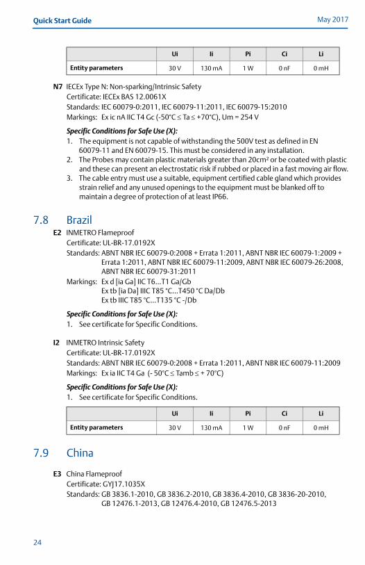
N7 IECEx Type N: Non-sparking/Intrinsic SafetyCertificate: IECEx BAS 12.0061XStandards: IEC 60079-0:2011, IEC 60079-11:2011, IEC 60079-15:2010 Markings: Ex ic nA IIC T4 Gc (-50°C Ta +70°C), Um = 254 V
Specific Conditions for Safe Use (X):1. The equipment is not capable of withstanding the 500V test as defined in EN
60079-11 and EN 60079-15. This must be considered in any installation.2. The Probes may contain plastic materials greater than 20cm² or be coated with plastic
and these can present an electrostatic risk if rubbed or placed in a fast moving air flow.3. The cable entry must use a suitable, equipment certified cable gland which provides
strain relief and any unused openings to the equipment must be blanked off to maintain a degree of protection of at least IP66.
7.8 BrazilE2 INMETRO Flameproof
Certificate: UL-BR-17.0192XStandards: ABNT NBR IEC 60079-0:2008 + Errata 1:2011, ABNT NBR IEC 60079-1:2009 +
Errata 1:2011, ABNT NBR IEC 60079-11:2009, ABNT NBR IEC 60079-26:2008, ABNT NBR IEC 60079-31:2011
Markings: Ex d [ia Ga] IIC T6...T1 Ga/GbEx tb [ia Da] IIIC T85 °C...T450 °C Da/DbEx tb IIIC T85 °C...T135 °C -/Db
Specific Conditions for Safe Use (X):1. See certificate for Specific Conditions.
I2 INMETRO Intrinsic SafetyCertificate: UL-BR-17.0192XStandards: ABNT NBR IEC 60079-0:2008 + Errata 1:2011, ABNT NBR IEC 60079-11:2009Markings: Ex ia IIC T4 Ga (- 50°C Tamb + 70°C)
Specific Conditions for Safe Use (X):1. See certificate for Specific Conditions.
7.9 China
E3 China FlameproofCertificate: GYJ17.1035XStandards: GB 3836.1-2010, GB 3836.2-2010, GB 3836.4-2010, GB 3836-20-2010,
GB 12476.1-2013, GB 12476.4-2010, GB 12476.5-2013
Ui Ii Pi Ci Li
Entity parameters 30 V 130 mA 1 W 0 nF 0 mH
Ui Ii Pi Ci Li
Entity parameters 30 V 130 mA 1 W 0 nF 0 mH
24
Quick Start GuideMay 2017
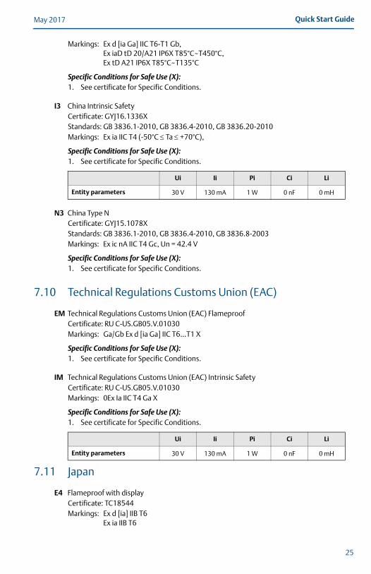
Markings: Ex d [ia Ga] IIC T6-T1 Gb,Ex iaD tD 20/A21 IP6X T85°C~T450°C,Ex tD A21 IP6X T85°C~T135°C
Specific Conditions for Safe Use (X):1. See certificate for Specific Conditions.
I3 China Intrinsic SafetyCertificate: GYJ16.1336XStandards: GB 3836.1-2010, GB 3836.4-2010, GB 3836.20-2010Markings: Ex ia IIC T4 (-50°C Ta +70°C),
Specific Conditions for Safe Use (X):1. See certificate for Specific Conditions.
N3 China Type NCertificate: GYJ15.1078XStandards: GB 3836.1-2010, GB 3836.4-2010, GB 3836.8-2003Markings: Ex ic nA IIC T4 Gc, Un = 42.4 V
Specific Conditions for Safe Use (X):1. See certificate for Specific Conditions.
7.10 Technical Regulations Customs Union (EAC)
EM Technical Regulations Customs Union (EAC) Flameproof Certificate: RU C-US.GB05.V.01030Markings: Ga/Gb Ex d [ia Ga] IIC T6…T1 X
Specific Conditions for Safe Use (X):1. See certificate for Specific Conditions.
IM Technical Regulations Customs Union (EAC) Intrinsic SafetyCertificate: RU C-US.GB05.V.01030Markings: 0Ex Ia IIC T4 Ga X
Specific Conditions for Safe Use (X):1. See certificate for Specific Conditions.
7.11 Japan
E4 Flameproof with displayCertificate: TC18544Markings: Ex d [ia] IIB T6
Ex ia IIB T6
Ui Ii Pi Ci Li
Entity parameters 30 V 130 mA 1 W 0 nF 0 mH
Ui Ii Pi Ci Li
Entity parameters 30 V 130 mA 1 W 0 nF 0 mH
25
May 2017Quick Start Guide
Specific Conditions for Safe Use (X):1. See certificate for Specific Conditions.
E4 Flameproof without displayCertificate: TC 18545Markings: Ex d [ia] IIB T6
Ex ia IIB T6
Specific Conditions for Safe Use (X):1. See certificate for Specific Conditions.
7.12 Republic of Korea
EP Korea FlameproofCertificate: 10-KB4BO-0019XMarkings: Ex d[ia] IIC T6
Specific Conditions for Safe Use (X):1. See certificate for Specific Conditions.
7.13 IndiaXX Flameproof
Certificate: P119297/1Markings: Ex d {ia Ga} IIC T6…T1 Ga/Gb
Specific Conditions for Safe Use (X):1. See certificate for Specific Conditions.
XX Intrinsically safeCertificate: P331362/1Markings: Ex ia IIC T4 Ga
Specific Conditions for Safe Use (X):1. See certificate for Specific Conditions.
XX Intrinsically safeCertificate: P314493/1Markings: Ex ia IIC T4 Ga/Gb
Ex ia/ib T4
Specific Conditions for Safe Use (X):1. See certificate for Specific Conditions.
7.14 Combinations
KA Combination of E1 and E6KB Combination of E5 and E6KC Combination of E1 and E5KD Combination of I1 and I6KE Combination of I5 and I6KF Combination of I1 and I5
26
Quick Start GuideMay 2017
7.15 Additional Certifications
Ü1 Overfill preventionCertificate: Z-65.16-416Application: TÜV tested and approved by DIBt for overfill prevention according to the
German WHG regulations.
7.16 Pattern Approval
GOST BelarusCertificate: RB-03 07 2765 10
GOST KazakhstanCertificate: KZ.02.02.03473-2013
GOST RussiaCertificate: SE.C.29.010.A
GOST UzbekistanCertificate: 02.2977-14
China Pattern ApprovalCertificate: 2009-L256
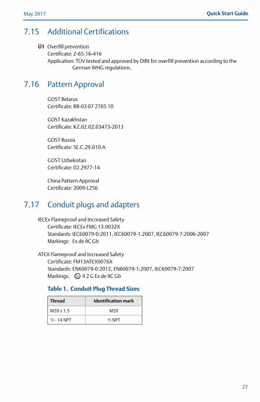
7.17 Conduit plugs and adapters
IECEx Flameproof and Increased SafetyCertificate: IECEx FMG 13.0032XStandards: IEC60079-0:2011, IEC60079-1:2007, IEC60079-7:2006-2007Markings: Ex de IIC Gb
ATEX Flameproof and Increased SafetyCertificate: FM13ATEX0076XStandards: EN60079-0:2012, EN60079-1:2007, IEC60079-7:2007Markings: II 2 G Ex de IIC Gb
Table 1. Conduit Plug Thread Sizes
Thread Identification mark
M20 x 1.5 M20
½ - 14 NPT ½ NPT
27

May 2017Quick Start Guide
Table 2. Thread Adapter Thread Sizes
Specific Conditions for Safe Use (X):1. When the thread adapter or blanking plug is used with an enclosure in type of
protection increased safety “e” the entry thread shall be suitably sealed in order to maintain the ingress protection rating (IP) of the enclosure. See certificate for Specific Conditions.
2. The blanking plug shall not be used with an adapter.3. Blanking Plug and Threaded Adapter shall be either NPT or Metric thread forms. G½
thread forms are only acceptable for existing (legacy) equipment installations.
Male thread Identification mark
M20 x 1.5 –6g M20
½ - 14 NPT ½ - 14 NPT
¾ - 14 NPT ¾ - 14 NPT
Female thread Identification mark
M20 x 1.5 –6H M20
½ - 14 NPT ½ - 14 NPT
G1/2 G1/2
28

Quick Start GuideMay 2017
Figure 9. EU Declaration of Conformity
EU Declaration of Conformity No: 3300
Manager Product Approvals (function name - printed)
Dajana Prastalo (name - printed)
(signature)
2017-04-11 (date of issue)
We,
Rosemount Tank Radar AB Layoutvägen 1 S-435 33 MÖLNLYCKESweden
declare under our sole responsibility that the product,
Rosemount 3300 Series Guided Wave Radar Level and Interface Transmitter
manufactured by,
Rosemount Tank Radar AB Layoutvägen 1 S-435 33 MÖLNLYCKESweden
is in conformity with the provisions of the European Community Directives, including the latest amendments, as shown in the attached schedule.
Presumption of conformity is based on the application of the harmonized standards, normative documents or other documents and, when applicable or required, a European Community notified body certification, as shown in attached schedule.
29
May 2017Quick Start Guide
Schedule No: 3300
Page 2 of 3
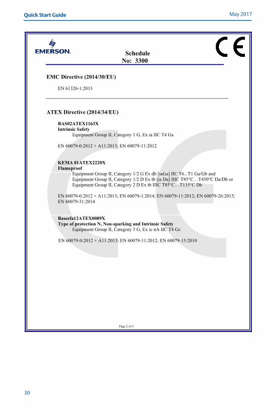
EMC Directive (2014/30/EU)
EN 61326-1:2013
ATEX Directive (2014/34/EU)
BAS02ATEX1163X Intrinsic Safety
Equipment Group II, Category 1 G, Ex ia IIC T4 Ga
EN 60079-0:2012 + A11:2013; EN 60079-11:2012
KEMA 01ATEX2220X Flameproof
Equipment Group II, Category 1/2 G Ex db [iaGa] IIC T6...T1 Ga/Gb and Equipment Group II, Category 1/2 D Ex tb [ia Da] IIIC T85°C…T450°C Da/Db or Equipment Group II, Category 2 D Ex tb IIIC T85°C…T135°C Db
EN 60079-0:2012 + A11:2013; EN 60079-1:2014; EN 60079-11:2012; EN 60079-26:2015; EN 60079-31:2014
Baseefa12ATEX0089X Type of protection N, Non-sparking and Intrinsic Safety
Equipment Group II, Category 3 G, Ex ic nA IIC T4 Gc
EN 60079-0:2012 + A11:2013; EN 60079-11:2012; EN 60079-15:2010
30
Quick Start GuideMay 2017
Schedule No: 3300
Page 3 of 3
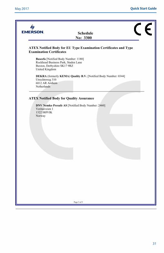
ATEX Notified Body for EU Type Examination Certificates and Type Examination Certificates
Baseefa [Notified Body Number: 1180] Rockhead Business Park, Staden Lane Buxton, Derbyshire SK17 9RZ United Kingdom
DEKRA (formerly KEMA) Quality B.V. [Notified Body Number: 0344] Utrechtsweg 310 6812 AR Arnhem Netherlands
ATEX Notified Body for Quality Assurance
DNV Nemko Presafe AS [Notified Body Number: 2460] Veritasveien 1 1322 HØVIK Norway
31
May 2017Quick Start Guide
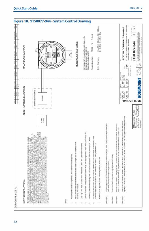
Figure 10. 9150077-944 - System Control Drawing
FM A
ppro
ved
Prod
uct
No
revi
sion
s to
this
dra
win
gw
ithou
t prio
r Fac
tory
Mut
ual
App
rova
l.
SME-
2917
0139
1IS
SU
EC
H. O
RD
ER
No
WEE
KIS
SU
EC
H. O
RD
ER
No
WEE
KIS
SU
EC
H. O
RD
ER
No
WEE
KIS
SU
EC
H. O
RD
ER
No
WEE
KA3
OR
IGIN
AL
SIZE
GU
-LN
0139
3300
GU
-PO
6P
DF
9150 077-94491
50 0
77-9
44
0139
SYST
EM C
ON
TRO
L D
RA
WIN
Gfo
r haz
ardo
us lo
catio
n in
stal
latio
n of
Intri
nsic
ally
Saf
e FM
app
rove
d ap
para
tus
51
/ 1
ISSU
ED B
Y
APPR
OVE
D B
Y
WEE
K
WEE
K
PR
OD
UC
T C
OD
E
DO
C. T
YPE
FILE
TITL
E
DW
G N
O.
ISS
UE
SHEE
T
SCAL
E
2:1
1 ST
AN
GLE
FIN
ISH
, UN
LESS
OTH
ERW
ISE
STAT
ED:
ALL
DIM
ENSI
ON
S AR
E IN
MIL
LIM
ETR
ES.
The
cop
yrig
ht/o
wne
rshi
p of
this
doc
umen
t is
and
will
rem
ain
ours
.T
he d
ocum
ent m
ust n
ot b
e us
ed w
ithou
t our
aut
horiz
atio
n or
bro
ught
to t
he k
now
ledg
e of
a th
ird p
arty
. Con
trave
ntio
n w
ill be
pro
secu
ted.
Ros
emou
nt T
ank
Rad
ar A
B, S
wed
en
ASS
OC
IATE
D A
PPA
RATU
S
BARR
IER
POW
ERSU
PPLY
ROSE
MO
UN
T 33
00 S
ERIE
S
Intr
insi
cally
Saf
e A
pp
arat
us
for u
se in
Cla
ss I,
II, I
II,D
ivis
ion
1, G
rou
ps
A, B
, C, D
, E, F
, GC
lass
I, Z
on
e 0,
AEx
ia II
C T
4
Tem
per
atu
re c
lass
:T4
(-50
<=
Ta
<=
70
deg
C)
Enti
ty P
aram
eter
s :
Vm
ax(U
i) <
= 3
0 V,
Imax
(Ii) <
= 1
30 m
AC
i = 0
nF,
Li =
0 u
H, P
i <=
1 W
HA
ZA
RDO
US
LOC
ATIO
NN
ON
-HA
ZA
RDO
US
LOC
ATIO
NEN
TITY
CO
NC
EPT
APP
RO
VAL
The
Enti
ty c
on
cep
t allo
ws
inte
rco
nn
ecti
on
of i
ntr
insi
cally
saf
e ap
par
atu
s to
ass
oci
ated
ap
par
atu
sn
ot s
pec
ifica
lly e
xam
ined
in c
om
bin
atio
n a
s a
syst
em.T
he
app
rove
d v
alu
es o
f max
. op
en c
ircu
itvo
ltag
e (V
oc
or V
t) a
nd
max
. sh
ort
cir
cuit
cu
rren
t (Is
c o
r It)
an
d m
ax. p
ower
(Vo
c x
Isc
/ 4)
or (
Vt x
It /
4),
for t
he
asso
ciat
ed a
pp
arat
us
mu
st b
e le
ss th
an o
r eq
ual
to th
e m
axim
um
saf
e in
pu
t vo
ltag
e (V
max
),m
axim
um
saf
e in
pu
t cu
rren
t (Im
ax),
and
max
imu
m s
afe
inp
ut p
ower
(Pm
ax) o
f th
e in
trin
sica
lly s
afe
app
arat
us.
In a
dd
itio
n, t
he
app
rove
d m
ax. a
llow
able
co
nn
ecte
d c
apac
itan
ce (C
a o
r Co
) of t
he
asso
ciat
edap
par
atu
s m
ust
be
gre
ater
than
the
sum
of t
he
inte
rco
nn
ecti
ng
cab
le c
apac
itan
ce a
nd
the
un
pro
tect
edin
tern
al c
apac
itan
ce (C
i) o
f th
e in
trin
sica
lly s
afe
app
arat
us,
and
the
the
app
rove
d m
ax. a
llow
able
con
nec
ted
ind
uct
ance
(La
or L
o) o
f th
e as
soci
ated
ap
par
atu
s m
ust
be
gre
ater
than
the
sum
of t
he
inte
rco
nn
ecti
ng
cab
le in
du
ctan
ce a
nd
the
un
pro
tect
ed in
tern
al in
du
ctan
ce (L
i) o
f th
e in
trin
sica
llysa
fe a
pp
arat
us.
No
tes:
1.N
o re
visi
on
to th
is d
raw
ing
wit
ho
ut p
rio
r Fac
tory
Mu
tual
ap
pro
val.
2.A
sso
ciat
ed a
pp
arat
us
man
ufa
ctu
rer's
inst
alla
tio
n d
raw
ing
mu
ste
be
follo
wed
wh
enin
stal
ling
this
pro
du
ct.
3.D
ust
-Tig
th s
eal m
ust
be
use
d w
hen
inst
alle
d in
Cla
ss II
an
d C
lass
III e
nvir
on
men
ts.
4.C
on
tro
l eq
uip
men
t co
nn
ecte
d to
the
bar
rier
mu
st n
ot u
se o
r gen
erat
e m
ore
than
250
Vrm
s o
r Vd
c.
5.Re
sist
ance
bet
wee
n In
trin
sica
lly S
afe
Gro
un
d a
nd
Ear
th G
rou
nd
mu
st b
e le
ss th
an 1
.0 o
hm
.
6.In
stal
lati
on
s sh
ou
ld b
e in
acc
ord
ance
wit
h A
NSI
/ISA
-RP1
2.6
"In
stal
lati
on
of I
ntr
insi
cally
Saf
eSy
stem
s fo
r Haz
ard
ou
s Lo
cati
on
s" a
nd
the
Nat
ion
al E
lect
ric
Co
de
(AN
SI/N
FPA
70)
.
7.Th
e as
soci
ated
ap
par
atu
s m
ust
be
Fact
ory
Mu
tual
Ap
pro
ved.
2SM
E-55
0306
433
SME-
5913
0805
4SM
E-71
1911
44
SME-
7961
1420
5
WA
RNIN
G :
To
pre
ven
t ig
nit
ion
of f
lam
mab
le o
r co
mb
ust
ible
atm
osp
her
es, r
ead
, u
nd
erst
and
an
d a
dh
ere
to t
he
man
ufa
ctu
rer's
live
mai
nte
nan
ce p
roce
du
res.
WA
RNIN
G:
Sub
stit
uti
on
of c
om
po
nen
ts m
ay im
pai
r In
trin
sic
Safe
ty.
WA
RNIN
G:
Pote
nti
al E
lect
rost
atic
Ch
arg
ing
Haz
ard
– T
he
encl
osu
re c
on
tain
s n
on
-met
allic
mat
eria
l. T
o p
reve
nt
the
risk
of e
lect
rost
atic
sp
arki
ng
th
e p
last
ic s
urf
ace
sho
uld
on
ly b
e cl
ean
ed w
ith
a d
amp
clo
th.
WA
RNIN
G:
The
app
arat
us
encl
osu
re c
on
tain
s al
um
inu
m a
nd
is c
on
sid
ered
to c
on
stit
ute
a p
ote
nti
al ri
sk o
f ig
nit
ion
by
imp
act
or f
rict
ion
. Car
e m
ust
be
take
n in
to a
cco
un
t d
uri
ng
inst
alla
tio
n a
nd
use
to p
reve
nt
imp
act
or f
rict
ion
.
32
Quick Start GuideMay 2017
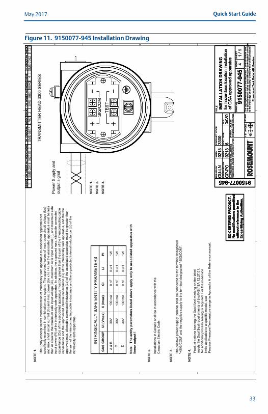
Figure 11. 9150077-945 Installation Drawing
D C B A
TRAN
SMIT
TER
HEA
D 3
300
SER
IES
The
Entit
y co
ncep
t allo
ws
inte
rcon
nect
ion
of in
trins
ical
ly s
afe
appa
ratu
s to
ass
ocia
ted
appa
ratu
s no
tsp
ecifi
cally
exa
min
ed in
com
bina
tion
as a
sys
tem
. The
app
rove
d va
lues
of m
ax. o
pen
circ
uit v
olta
ge (U
o)an
d m
ax. s
hort
circ
uit c
urre
nt (I
o) a
nd m
ax. p
ower
(Uo
x Io
/ 4)
, for
the
asso
ciat
ed a
ppar
atus
mus
t be
less
than
or e
qual
to th
e m
axim
um s
afe
inpu
t vol
tage
(Ui),
max
imum
saf
e in
put c
urre
nt (I
i), a
nd m
axim
um s
afe
inpu
t pow
er (P
i) of
the
intri
nsic
ally
saf
e ap
para
tus.
In a
dditi
on, t
he a
ppro
ved
max
. allo
wab
le c
onne
cted
capa
cita
nce
(Co)
of t
he a
ssoc
iate
d ap
para
tus
mus
t be
grea
ter t
han
the
sum
of t
he in
terc
onne
ctin
g ca
ble
capa
cita
nce
and
the
unpr
otec
ted
inte
rnal
cap
acita
nce
(Ci)
of th
e in
trins
ical
ly s
afe
appa
ratu
s, a
nd th
e th
eap
prov
ed m
ax. a
llow
able
con
nect
ed in
duct
ance
(Lo)
of t
he a
ssoc
iate
d ap
para
tus
mus
t be
grea
ter t
han
the
sum
of t
he in
terc
onne
ctin
g ca
ble
indu
ctan
ce a
nd th
e un
prot
ecte
d in
tern
al in
duct
ance
(Li)
of th
ein
trins
ical
ly s
afe
appa
ratu
s.
D
INTR
INSI
CAL
LY S
AFE
ENTI
TY P
ARAM
ETER
S
A &
BC
GA
S G
RO
UP
The
posi
tive
pow
er s
uppl
y te
rmin
al s
hall
be c
onne
cted
to th
e te
rmin
al d
esig
nate
d"+
SIG
/CO
M" a
nd th
e ne
gativ
e su
pply
to th
e te
rmin
al d
esig
nate
d "-
SIG
/CO
M".
Inst
alla
tions
in C
anad
a sh
all b
e in
acc
orda
nce
with
the
Can
adia
n El
ectri
c C
ode.
Pow
er S
uppl
y an
dou
tput
sig
nal
Ui (
Vmax
)Ii
(Imax
)C
iLi
Pi
NO
TE 1
.
30V
30V
30V
1W 1W 1W
0 nF
0 nF
0 nF
0 uH
0 uH
0 uH
130
mA
130
mA
130
mA
NO
TE 2
.
NO
TE 1
.
NO
TE 2
.
NO
TE 3
.
Not
e : T
he e
ntity
par
amet
ers
liste
d ab
ove
appl
y on
ly to
ass
ocia
ted
appa
ratu
s w
ithlin
ear o
utpu
t !
NO
TE 3
.
Pro
duct
opt
ions
bea
ring
the
Dua
l Sea
l mar
king
on
the
labe
l m
eets
the
Dua
l Sea
l req
uire
men
ts o
f the
AN
SI/I
SA
12.
27.0
1.N
o ad
ditio
nal p
roce
ss s
ealin
g is
requ
ired.
For
the
in-s
ervi
celim
its a
pplic
able
to a
spe
cific
mod
el, s
eeP
roce
ss P
ress
ure/
Tem
pera
ture
rang
e in
App
endi
x A
of t
he R
efer
ence
man
ual.
NO
TE 4
.
13
42
SM
E-5
617
SM
E-5
983
SM
E-7
062
SM
E-2
918
0213
0707
0840
1121
ISS
UE
CH
. O
RD
ER
No
WE
EK
ISS
UE
CH
. O
RD
ER
No
WE
EK
ISS
UE
CH
. O
RD
ER
No
WE
EK
ISS
UE
CH
. O
RD
ER
No
WE
EK
ISS
UE
CH
. O
RD
ER
No
WE
EK
ISS
UE
CH
. O
RD
ER
No
WE
EK
ISS
UE
CH
. O
RD
ER
No
WE
EK
ISS
UE
CH
. O
RD
ER
No
WE
EK
ISS
UE
CH
. O
RD
ER
No
WE
EK
ISS
UE
CH
. O
RD
ER
No
WE
EK
ISS
UE
CH
. O
RD
ER
No
WE
EK
ISS
UE
CH
. O
RD
ER
No
WE
EK
ISS
UE
D B
Y
AP
PR
OV
ED
BY
WE
EK
WE
EK
PR
OD
UC
T C
OD
E
DO
C.
TY
PE
FIL
E
TIT
LE
DW
G N
O.
ISS
UE
SH
EE
T
SC
AL
E1
ST
AN
GL
E
FIN
ISH
, U
NL
ES
SO
TH
ER
WIS
E S
TA
TE
D:
Th
e c
op
yrig
ht/
ow
ne
rsh
ip o
f th
is d
ocu
me
nt
is a
nd
will
re
ma
in o
urs
.T
he
do
cum
en
t m
ust
no
t b
e u
sed
with
ou
t o
ur
au
tho
riza
tion
or
bro
ug
ht
to t
he
kn
ow
led
ge
of
a t
hird
pa
rty.
Co
ntr
ave
ntio
n w
ill b
e p
rose
cute
d.
Ros
emou
nt T
ank
Rad
ar A
B, S
wed
en
ALL
DIM
EN
SIO
NS
AR
E IN
MIL
LIM
ETR
ES
.TO
LER
AN
CE
S, U
NLE
SS
OTH
ER
WIS
E S
TATE
D:
GU
-LN
0213
3300
GP-
PO6
OrCA
D
9150
077-
945
0213
INST
ALL
ATI
ON
DR
AW
ING
for h
azar
dous
loca
tion
inst
alla
tion
41
/ 1
of C
SA
app
rove
d ap
para
tus
ISS
UE
D B
Y
AP
PR
OV
ED
BY
WE
EK
WE
EK
PR
OD
UC
T C
OD
E
DO
C.
TY
PE
FIL
E
TIT
LE
DW
G N
O.
ISS
UE
SH
EE
T
SC
AL
E1
ST
AN
GL
E
FIN
ISH
, U
NL
ES
SO
TH
ER
WIS
E S
TA
TE
D:
Th
e c
op
yrig
ht/
ow
ne
rsh
ip o
f th
is d
ocu
me
nt
is a
nd
will
re
ma
in o
urs
.T
he
do
cum
en
t m
ust
no
t b
e u
sed
with
ou
t o
ur
au
tho
riza
tion
or
bro
ug
ht
to t
he
kn
ow
led
ge
of
a t
hird
pa
rty.
Co
ntr
ave
ntio
n w
ill b
e p
rose
cute
d.
Ros
emou
nt T
ank
Rad
ar A
B, S
wed
en
ALL
DIM
EN
SIO
NS
AR
E IN
MIL
LIM
ETR
ES
.TO
LER
AN
CE
S, U
NLE
SS
OTH
ER
WIS
E S
TATE
D:
GU
-LN
0213
3300
GP-
PO6
OrCA
D
9150
077-
945
0213
INST
ALL
ATI
ON
DR
AW
ING
for h
azar
dous
loca
tion
inst
alla
tion
41
/ 1
of C
SA
app
rove
d ap
para
tus
EX-C
ERTI
FIED
PR
OD
UC
T.N
o m
odifi
catio
ns p
erm
itted
with
out r
efer
ence
to th
eEx
-cer
tifyi
ng A
utho
ritie
s.
EX-C
ERTI
FIED
PR
OD
UC
T.N
o m
odifi
catio
ns p
erm
itted
with
out r
efer
ence
to th
eEx
-cer
tifyi
ng A
utho
ritie
s.
EX-C
ERTI
FIED
PR
OD
UC
T.N
o m
odifi
catio
ns p
erm
itted
with
out r
efer
ence
to th
eEx
-cer
tifyi
ng A
utho
ritie
s.
33
May 2017Quick Start Guide
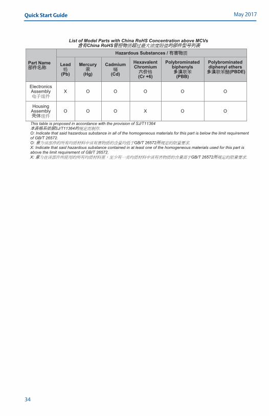
List of Model Parts with China RoHS Concentration above MCVs 含含有China RoHS管控物 超 的部件型号列表
Part Name 部件名称
Hazardous Substances / 有害物
Lead
(Pb)
Mercury 汞
(Hg)
Cadmium
(Cd)
Hexavalent Chromium
(Cr +6)
Polybrominated biphenyls
(PBB)
Polybrominated diphenyl ethers
(PBDE)
Electronics Assembly X O O O O O
Housing Assembly 体
O O O X O O
This table is proposed in accordance with the provision of SJ/T11364 本表格系依据SJ/T11364的O: Indicate that said hazardous substance in all of the homogeneous materials for this part is below the limit requirement of GB/T 26572. O:意 GB/T 26572所X: Indicate that said hazardous substance contained in at least one of the homogeneous materials used for this part is above the limit requirement of GB/T 26572. X:意 GB/T 26572所
34

Quick Start GuideMay 2017
35

Manufactured byEmerson Automation Solutions Rosemount Tank Radar ABLayoutvägen 1S-435 33 MölnlyckeSweden
+46 31 337 00 00+46 31 25 30 22
Global HeadquartersEmerson Automation Solutions6021 Innovation Blvd.Shakopee, MN 55379, USA
+1 800 999 9307 or +1 952 906 8888+1 952 949 7001 [email protected]
North America Regional OfficeEmerson Automation Solutions8200 Market Blvd.Chanhassen, MN 55317, USA
+1 800 999 9307 or +1 952 906 8888
+1 952 949 7001
Linkedin.com/company/Emerson-Automation-Solutions
Twitter.com/Rosemount_News
Facebook.com/Rosemount
Youtube.com/user/RosemountMeasurement
Google.com/+RosemountMeasurement
Standard Terms and Conditions of Sale can be found on the Terms and Conditions of Sale page.The Emerson logo is a trademark and service mark of Emerson Electric Co.Tri-Loop, Emerson Process Management, Rosemount and Rosemount logotype are trademarks of Emerson Process Management.HART is a registered trademark of the FieldComm Group.Modbus is a registered trademark of Gould Inc.DTM is a trademark of the FDT Group.National Electrical Code is a registered trademark of National Fire Protection Association, Inc.All other marks are the property of their respective owners.© 2017 Emerson. All rights reserved.
Latin America Regional OfficeEmerson Automation Solutions1300 Concord Terrace, Suite 400Sunrise, FL 33323, USA
+1 954 846 5030
+1 954 846 5121
Europe Regional OfficeEmerson Automation SolutionsNeuhofstrasse 19a P.O. Box 1046CH 6340 BaarSwitzerland
+41 (0) 41 768 6111
+41 (0) 41 768 6300
Asia Pacific Regional OfficeEmerson Automation Solutions1 Pandan CrescentSingapore 128461
+65 6777 8211
+65 6777 0947 [email protected]
Middle East and Africa Regional OfficeEmerson Automation SolutionsEmerson FZE P.O. Box 17033Jebel Ali Free Zone - South 2Dubai, United Arab Emirates
+971 4 8118100
+971 4 [email protected]
Quick Start Guide00825-0100-4811, Rev JB
May 2017
*00825-0100-4811*