jawaharlal nehru technological university … · and solving assignment & tutorial problems....
TRANSCRIPT
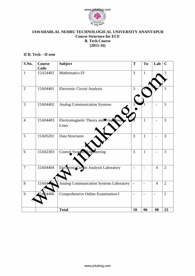
JAWAHARLAL NEHRU TECHNOLOGICAL UNIVERSITY ANANTAPUR Course Structure for ECE
B. Tech Course (2015-16)
II B. Tech – II sem S.No. Course
Code Subject T Tu Lab C
1 15A54402 Mathematics-IV
3 1 - 3
2 15A04401 Electronic Circuit Analysis
3 1 - 3
3 15A04402 Analog Communication Systems
3 1 - 3
4 15A04403 Electromagnetic Theory and Transmission Lines
3 1 - 3
5 15A05201 Data Structures
3 1 - 3
6 15A02303 Control Systems Engineering
3 1 - 3
7 15A04404 Electronic Circuit Analysis Laboratory
- - 4 2
8 15A04405 Analog Communication Systems Laboratory
- - 4 2
9 15A04406 Comprehensive Online Examination-I
- - - 1
Total 18 06 08 23
www.jntuking.com
www.jntuking.com
www.jntuk
ing.co
m
JAWAHARLAL NEHRU TECHNOLOGICAL UNIVERSITY ANANTAPUR
II B.Tech II-Sem (E.C.E) T Tu C
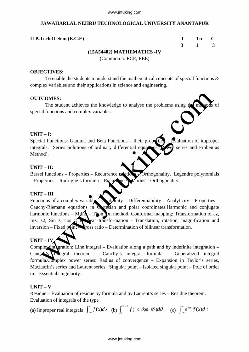
3 1 3 (15A54402) MATHEMATICS -IV
(Common to ECE, EEE) OBJECTIVES:
To enable the students to understand the mathematical concepts of special functions & complex variables and their applications in science and engineering.
OUTCOMES:
The student achieves the knowledge to analyse the problems using the methods of special functions and complex variables
UNIT – I: Special Functions: Gamma and Beta Functions – their properties – Evaluation of improper integrals. Series Solutions of ordinary differential equations (Power series and Frobenius Method). UNIT – II: Bessel functions – Properties – Recurrence relations – Orthogonality. Legendre polynomials – Properties – Rodrigue’s formula – Recurrence relations – Orthogonality. UNIT – III Functions of a complex variable – Continuity – Differentiability – Analyticity – Properties – Cauchy-Riemann equations in Cartesian and polar coordinates.Harmonic and conjugate harmonic functions – Milne – Thomson method. Conformal mapping: Transformation of ez, Inz, z2, Sin z, cos z, Bilinear transformation - Translation, rotation, magnification and inversion – Fixed point – Cross ratio – Determination of bilinear transformation. UNIT – IV Complex integration: Line integral – Evaluation along a path and by indefinite integration – Cauchy’s integral theorem – Cauchy’s integral formula – Generalized integral formula.Complex power series: Radius of convergence – Expansion in Taylor’s series, Maclaurin’s series and Laurent series. Singular point – Isolated singular point – Pole of order m – Essential singularity. UNIT – V Residue – Evaluation of residue by formula and by Laurent’s series – Residue theorem. Evaluation of integrals of the type
(a) Improper real integrals ∫∞
∞−d xxf )( (b) ∫
+ πθθθ
2)s i n,( c o s
c
cdf (c) ∫
∞
∞−d xxfei m x )(
www.jntuking.com
www.jntuking.com
www.jntuk
ing.co
m

TEXT BOOKS: 1.Higher Engineering Mathematics, B.S.Grewal, Khanna publishers. 2.Engineering Mathematics, Volume - III, E. Rukmangadachari & E. Keshava Reddy, Pearson Publisher REFERENCES: 1. Mathematics III by T.K.V. Iyengar, B.Krishna Gandhi, S.Ranganatham and M.V.S.S.N.Prasad, S.Chand publications. 2. Advanced Engineering Mathematics, Peter V.O’Neil, CENGAGE publisher. 3. Advanced Engineering Mathematics by M.C. Potter, J.L. Goldberg, Edward F.Aboufadel, Oxford.
www.jntuking.com
www.jntuking.com
www.jntuk
ing.co
m

JAWAHARLAL NEHRU TECHNOLOGICAL UNIVERSITY ANANTAPUR
II B.Tech II-Sem (E.C.E) T Tu C
3 1 3 (15A04401) ELECTRONIC CIRCUIT ANALYSIS
Course Objectives: The aim of this course is to familiarize the student with the analysis and design of multistage amplifiers with compound connections, feedback amplifiers, oscillators, power amplifiers and tuned amplifiers. To study and analyze the frequency response of amplifier circuits. Course Outcomes: Upon completion of this course, student will be able to :
• Analyze the frequency response of the BJT amplifiers at low and high frequencies. • Analyze and design multistage amplifiers with compound connections, feedback
amplifiers, oscillators, power amplifiers and tuned amplifiers.
UNIT -I Feedback Amplifiers : Feedback principle and concept, types of feedback, classification of amplifiers, feedback topologies,Characteristics of negative feedback amplifiers, Generalized analysis of feedback amplifiers, Performance comparison of feedback amplifiers, Method of Analysis of Feedback Amplifiers.
Oscillators: Oscillator principle, condition for oscillations, types of oscillators, RC-phase shift and Wein bridge oscillators with BJT and FET with the relevant analysis,Generalized analysis of LC Oscillators, Hartley and Colpitt’s oscillators with BJT and FET with relevant analysis, Crystal oscillators, Frequency and amplitude stability of oscillators.
UNIT- II Small Signal High Frequency Transistor Amplifier models: BJT: Transistor at High Frequencies, Hybrid- π Common Emitter transistor model, Hybrid π conductances, Hybrid π capacitances, Validity of hybrid π model, determination of high-frequency parameters in terms of low-frequency parameters , CE short circuit current gain, Current gain with resistive load, Cut-off frequencies, Frequency Response and Gain Bandwidth product.
FET:Analysis of Common Source and Common Drain Amplifier circuits at High frequencies.
UNIT – III Multistage Amplifiers : Classification ofamplifiers, Methods of coupling, Cascaded transistor amplifier and its analysis, Analysis of two stage RC coupled amplifier, High input resistance transistor amplifier circuits and their analysis-Darlington pair amplifier, Cascode
www.jntuking.com
www.jntuking.com
www.jntuk
ing.co
m
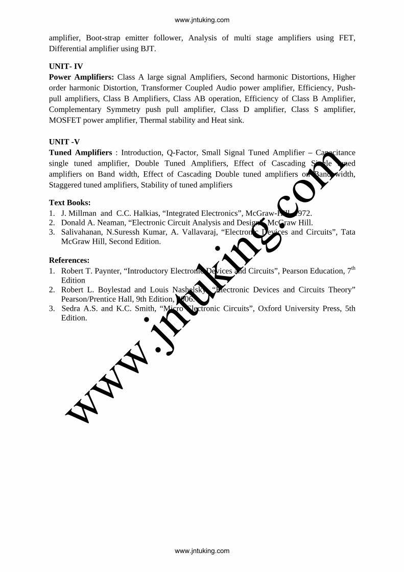
amplifier, Boot-strap emitter follower, Analysis of multi stage amplifiers using FET, Differential amplifier using BJT.
UNIT- IV Power Amplifiers: Class A large signal Amplifiers, Second harmonic Distortions, Higher order harmonic Distortion, Transformer Coupled Audio power amplifier, Efficiency, Push-pull amplifiers, Class B Amplifiers, Class AB operation, Efficiency of Class B Amplifier, Complementary Symmetry push pull amplifier, Class D amplifier, Class S amplifier, MOSFET power amplifier, Thermal stability and Heat sink. UNIT -V Tuned Amplifiers : Introduction, Q-Factor, Small Signal Tuned Amplifier – Capacitance single tuned amplifier, Double Tuned Amplifiers, Effect of Cascading Single tuned amplifiers on Band width, Effect of Cascading Double tuned amplifiers on Band width, Staggered tuned amplifiers, Stability of tuned amplifiers
Text Books: 1. J. Millman and C.C. Halkias, “Integrated Electronics”, McGraw-Hill, 1972. 2. Donald A. Neaman, “Electronic Circuit Analysis and Design”, McGraw Hill. 3. Salivahanan, N.Suressh Kumar, A. Vallavaraj, “Electronic Devices and Circuits”, Tata
McGraw Hill, Second Edition.
References: 1. Robert T. Paynter, “Introductory Electronic Devices and Circuits”, Pearson Education, 7th
Edition 2. Robert L. Boylestad and Louis Nashelsky, “Electronic Devices and Circuits Theory”
Pearson/Prentice Hall, 9th Edition, 2006. 3. Sedra A.S. and K.C. Smith, “Micro Electronic Circuits”, Oxford University Press, 5th
Edition.
www.jntuking.com
www.jntuking.com
www.jntuk
ing.co
m

JAWAHARLAL NEHRU TECHNOLOGICAL UNIVERSITY ANANTAPUR
II B.Tech II-Sem (E.C.E) T Tu C
3 1 3 (15A04402) ANALOG COMMUNICATION SYSTEMS
Course Objectives: • To study the fundamental concept of the analog communication systems. • To analyze various analog modulation and demodulation techniques. • To know the working of various transmitters and receivers. • To understand the influence of noise on the performance of analog communication
systems, and to acquire the knowledge about information and capacity. Learning Outcomes: This course provides the foundational education in Analog Communication systems, and applications. The students are provided the learning experience through class room teaching and solving assignment & tutorial problems. At the end of course, students should be able to: • Acquire knowledge on the basic concepts of Analog Communication Systems. • Analyze the analog modulated and demodulated systems. • Verify the effect of noise on the performance of communication systems. • Know the fundamental concepts of information and capacity. UNIT- I Introduction: Elements of communication systems, Information, Messages and Signals, Modulation, Modulation Methods, Modulation Benefits and Applications. Amplitude Modulation & Demodulation: Baseband and carrier communication, Amplitude Modulation (AM), Rectifier detector, Envelope detector, Double sideband suppressed carrier (DSB-SC) modulation & its demodulation, Switching modulators, Ring modulator, Balanced modulator, Frequency mixer, sideband and carrier power of AM, Generation of AM signals, Quadrature amplitude modulation (QAM), Single sideband (SSB) transmission, Time domain representation of SSB signals & their demodulation schemes (with carrier, and suppressed carrier), Generation of SSB signals, Vestigial sideband (VSB) modulator & demodulator, Illustrative Problems. UNIT- II Angle Modulation &Demodulation: Concept of instantaneous frequency, Generalized concept of angle modulation, Bandwidth of angle modulated waves – Narrow band frequency modulation (NBFM); and Wide band FM (WBFM), Phase modulation, Verification of Frequency modulation bandwidth relationship, Features of angle modulation, Generation of FM waves – Indirect method, Direct generation; Demodulation of FM, Bandpass limiter, Practical frequency demodulators, Small error analysis, Pre-emphasis, & De-emphasis filters, FM receiver, FM Capture Effect,. Carrier Acquisition- phased locked loop (PLL), Costas loop, Frequency division multiplexing (FDM), and Super-heterodyne AM receiver, Illustrative Problems. UNIT- III Noise in Communication Systems: Types of noise, Time domain representation of narrowband noise, Filtered white noise, Quadrature representation of narrowband noise,
www.jntuking.com
www.jntuking.com
www.jntuk
ing.co
m

Envelope of narrowband noise plus sine wave, Signal to noise ratio & probability of error, Noise equivalent bandwidth, Effective noise temperature, and Noise figure, Baseband systems with channel noise, Performance analysis (i.e. finding SNR expression) of AM, DSB-SC, SSB-SC, FM, PM in the presence of noise, Illustrative Problems. UNIT- IV Analog pulse modulation schemes: Pulse amplitude modulation – Natural sampling, flat top sampling and Pulse amplitude modulation (PAM) & demodulation, Pulse-Time Modulation – Pulse Duration and Pulse Position modulations, and demodulation schemes, PPM spectral analysis, Illustrative Problems. Radio Receiver measurements: Sensitivity, Selectivity, and fidelity. UNIT- V Information & Channel Capacity: Introduction, Information content of message, Entropy, Entropy of symbols in long independent and dependent sequences, Entropy and information rate of Markoff sources, Shannon’s encoding algorithm, Discrete communication channels, Rate of information over a discrete channel, Capacity of discrete memoryless channels, Discrete channels with memory, Shannon – Hartley theorem and its implications, Illustrative problems. Text books:
1. B. P. Lathi, “Modern Digital and Analog Communication Systems,” Oxford Univ. press, 3rd Edition, 2006.
2. Sham Shanmugam, “Digital and Analog Communication Systems”, Wiley-India edition, 2006.
3. A. Bruce Carlson, & Paul B. Crilly, “Communication Systems – An Introduction to Signals & Noise in Electrical Communication”, McGraw-Hill International Edition, 5th Edition, 2010.
References: 1. Simon Haykin, “Communication Systems”, Wiley-India edition, 3rd edition, 2010. 2. Herbert Taub& Donald L Schilling, “Principles of Communication Systems”, Tata
McGraw-Hill, 3rd Edition, 2009. 3. R.E. Ziemer& W.H. Tranter, “Principles of Communication-Systems Modulation &
Noise”, Jaico Publishing House, 2001. 4. George Kennedy and Bernard Davis, “Electronics & Communication System”, TMH,
2004.
www.jntuking.com
www.jntuking.com
www.jntuk
ing.co
m
JAWAHARLAL NEHRU TECHNOLOGICAL UNIVERSITY ANANTAPUR
II B.Tech II-Sem (E.C.E) T Tu C
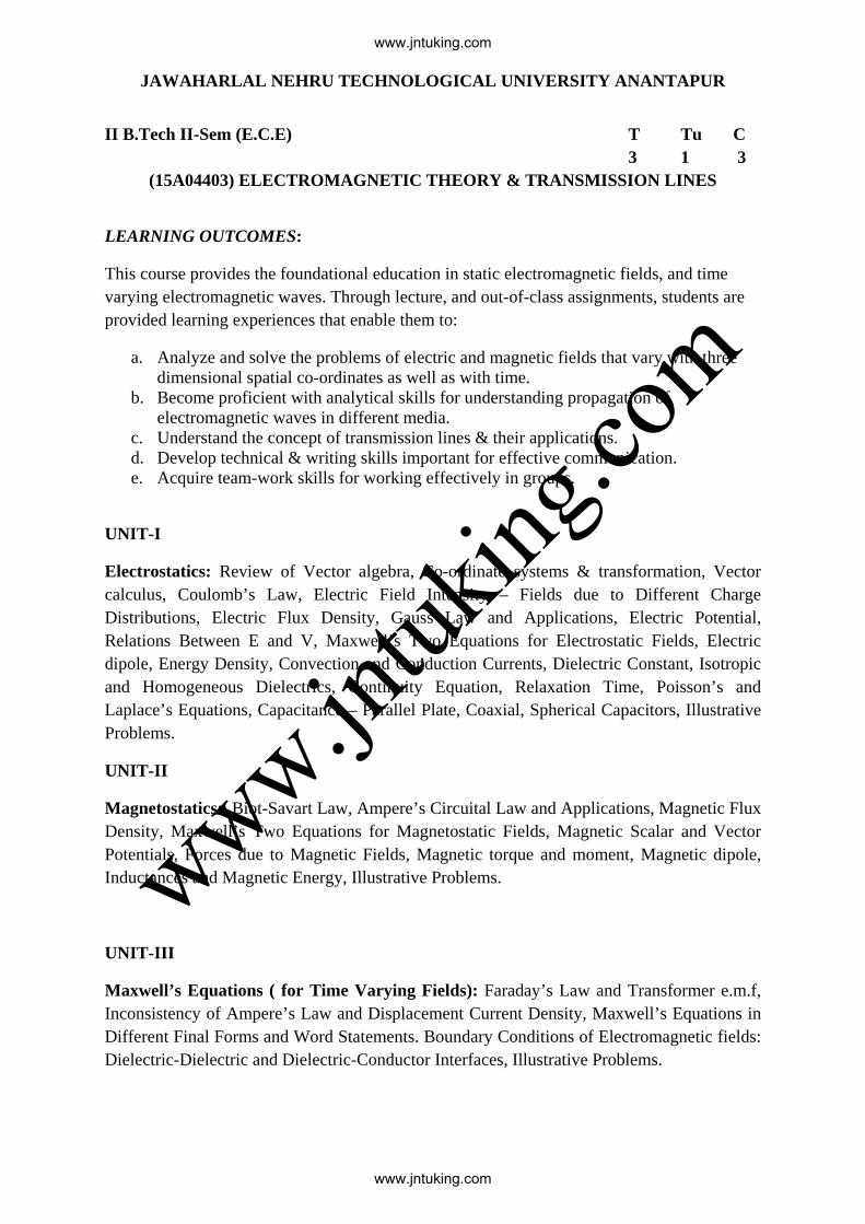
3 1 3 (15A04403) ELECTROMAGNETIC THEORY & TRANSMISSION LINES
LEARNING OUTCOMES:
This course provides the foundational education in static electromagnetic fields, and time varying electromagnetic waves. Through lecture, and out-of-class assignments, students are provided learning experiences that enable them to:
a. Analyze and solve the problems of electric and magnetic fields that vary with three dimensional spatial co-ordinates as well as with time.
b. Become proficient with analytical skills for understanding propagation of electromagnetic waves in different media.
c. Understand the concept of transmission lines & their applications. d. Develop technical & writing skills important for effective communication. e. Acquire team-work skills for working effectively in groups.
UNIT-I
Electrostatics: Review of Vector algebra, Co-ordinate systems & transformation, Vector calculus, Coulomb’s Law, Electric Field Intensity – Fields due to Different Charge Distributions, Electric Flux Density, Gauss Law and Applications, Electric Potential, Relations Between E and V, Maxwell’s Two Equations for Electrostatic Fields, Electric dipole, Energy Density, Convection and Conduction Currents, Dielectric Constant, Isotropic and Homogeneous Dielectrics, Continuity Equation, Relaxation Time, Poisson’s and Laplace’s Equations, Capacitance – Parallel Plate, Coaxial, Spherical Capacitors, Illustrative Problems.
UNIT-II
Magnetostatics: Biot-Savart Law, Ampere’s Circuital Law and Applications, Magnetic Flux Density, Maxwell’s Two Equations for Magnetostatic Fields, Magnetic Scalar and Vector Potentials, Forces due to Magnetic Fields, Magnetic torque and moment, Magnetic dipole, Inductances and Magnetic Energy, Illustrative Problems.
UNIT-III
Maxwell’s Equations ( for Time Varying Fields): Faraday’s Law and Transformer e.m.f, Inconsistency of Ampere’s Law and Displacement Current Density, Maxwell’s Equations in Different Final Forms and Word Statements. Boundary Conditions of Electromagnetic fields: Dielectric-Dielectric and Dielectric-Conductor Interfaces, Illustrative Problems.
www.jntuking.com
www.jntuking.com
www.jntuk
ing.co
m
UNIT-IV
EM Wave Characteristics: Wave Equations for Conducting and Perfect Dielectric Media, Uniform Plane Waves – Definition, All Relations between E & H, Sinusoidal Variations, Wave Propagation in Lossless and Conducting Media, Conductors & Dielectrics – Characterization, Wave Propagation in Good Conductors and Good Dielectrics, Polarization,Reflection and Refraction of Plane Waves – Normal and Oblique Incidences, for both Perfect Conductor and Perfect Dielectrics, Brewster Angle, Critical Angle and Total Internal Reflection, Surface Impedance, Poynting Vector, and Poynting Theorem – Applications, Power Loss in a Plane Conductor, Illustrative Problems.
UNIT-V
Transmission Lines: Types, Transmission line parameters (Primary and Secondary), Transmission line equations, Input impedance, Standing wave ratio & power, Smith chart & its applications, Applications of transmission lines of various lengths, Micro-strip transmission lines – input impedance, Illustrative Problems.
TEXT BOOKS:
1. Matthew N.O. Sadiku, “Elements of Electromagnetics,” Oxford Univ. Press, 4th ed., 2008. 2. William H. Hayt Jr. and John A. Buck, “Engineering Electromagnetics,” TMH, 7th ed.,
2006.
REFERENCES:
1. Electromagnetic Waves and Radiating Systems – E.C. Jordan and K.G. Balmain, PHI, 2nd Ed., 2000.
2. Electromagnetics – John D. Krauss, McGraw- Hill publications, 3rd ed., 1988. 3. John D. Ryder, “Networks, Lines, and Fields,” PHI publications, Second Edition, 2012. 4. Schaum’s out – lines, “Electromagnetics,” Second Edition, Tata McGraw-Hill
publications, 2006. 5. G. S. N. Raju, “Electromagnetic Field Theory and Transmission Lines,” Pearson
Education, 2013 6. N. NarayanaRao, “Fundamentals of Electromagnetics for Engineering,” Pearson Edu.
2009.
www.jntuking.com
www.jntuking.com
www.jntuk
ing.co
m

JAWAHARLAL NEHRU TECHNOLOGICAL UNIVERSITY ANANTAPUR
II B.Tech II-Sem (E.C.E) T Tu C
3 1 3 (15A05201) DATA STRUCTURES
Objectives: Understand different Data Structures Understand Searching and Sorting techniques Unit-1 Introduction and overview: Asymptotic Notations, One Dimensional array- Multi Dimensional array- pointer arrays. Linked lists: Definition- Single linked list- Circular linked list- Double linked list- Circular Double linked list- Application of linked lists. Unit-2 Stacks: Introduction-Definition-Representation of Stack-Operations on Stacks- Applications of Stacks. Queues: Introduction, Definition- Representations of Queues- Various Queue Structures- Applications of Queues. Tables: Hash tables. Unit-3 Trees: Basic Terminologies- Definition and Concepts- Representations of Binary Tree- Operation on a Binary Tree- Types of Binary Trees-Binary Search Tree, Heap Trees, Height Balanced Trees, B. Trees, Red Black Trees. Graphs: Introduction- Graph terminologies- Representation of graphs- Operations on Graphs- Application of Graph Structures: Shortest path problem- topological sorting. Unit-4 Sorting : Sorting Techniques- Sorting by Insertion: Straight Insertion sort- List insertion sort- Binary insertion sort- Sorting by selection: Straight selection sort- Heap Sort- Sorting by Exchange- Bubble Sort- Shell Sort-Quick Sort-External Sorts: Merging Order Files-Merging Unorder Files- Sorting Process. Unit-5 Searching: List Searches- Sequential Search- Variations on Sequential Searches- Binary Search- Analyzing Search Algorithm- Hashed List Searches- Basic Concepts- Hashing Methods- Collision Resolutions- Open Addressing- Linked List Collision Resolution- Bucket Hashing. Text Books: 1. “Classic Data Structures”, Second Edition by Debasis Samanta, PHI. 2. “Data Structures A Pseudo code Approach with C”, Second Edition by Richard F. Gilberg, Behrouz A. Forouzan, Cengage Learning.
www.jntuking.com
www.jntuking.com
www.jntuk
ing.co
m

Reference Books: 1. Fundamentals of Data Structures in C – Horowitz, Sahni, Anderson- Freed, Universities Press, Second Edition. 2. Schaum’ Outlines – Data Structures – Seymour Lipschutz – McGrawHill- Revised First Edition. 3. Data structures and Algorithms using C++, Ananda Rao Akepogu and Radhika Raju Palagiri, Pearson Education.
www.jntuking.com
www.jntuking.com
www.jntuk
ing.co
m

JAWAHARLAL NEHRU TECHNOLOGICAL UNIVERSITY ANANTAPUR
II B.Tech II-Sem (E.C.E) T Tu C
3 1 3 (15A02303) CONTROL SYSTEMS ENGINEERING
OBJECTIVES: To make the students learn about:
• Merits and demerits of open loop and closed loop systems; the effects of feedback
• The use of block diagram algebra and Mason’s gain formula to find the effective
transfer function between two nodes
• Transient and steady state responses , time domain specifications
• The concept of Root loci
• Frequency domain specifications, Bode diagrams and Nyquist plots
• The fundamental aspects of modern control
UNIT – I INTRODUCTION Open Loop and closed loop control systems and their differences- Examples of control
systems- Classification of control systems, Feedback Characteristics, Effects of positive and
negative feedback. Mathematical models – Differential equations of Translational and
Rotational mechanical systems, and Electrical Systems, Block diagram reduction methods –
Signal flow graph - Reduction using Mason’s gain formula. Transfer Function of DC Servo
motor - AC Servo motor - Synchro transmitter and Receiver
UNIT-II TIME RESPONSE ANALYSIS Step Response - Impulse Response - Time response of first order systems – Characteristic
Equation of Feedback control systems, Transient response of second order systems - Time
domain specifications – Steady state response - Steady state errors and error constants
UNIT – III STABILITY The concept of stability – Routh’s stability criterion – Stability and conditional stability –
limitations of Routh’s stability. The root locus concept - construction of root loci-effects of
adding poles and zeros to G(s)H(s) on the root loci.
UNIT – IV FREQUENCY RESPONSE ANALYSIS Introduction, Frequency domain specifications-Bode diagrams-Determination of Frequency
domain specifications and transfer function from the Bode Diagram-Stability Analysis from
Bode Plots. Polar Plots-Nyquist Plots- Phase margin and Gain margin-Stability Analysis.
www.jntuking.com
www.jntuking.com
www.jntuk
ing.co
m

Compensation techniques – Lag, Lead, Lag-Lead Compensator design in frequency Domain.
UNIT – V STATE SPACE ANALYSIS Concepts of state, state variables and state model, derivation of state models from differential
equations. Transfer function models. Block diagrams. Diagonalization. Solving the Time
invariant state Equations- State Transition Matrix and it’s Properties. System response
through State Space models. The concepts of controllability and observability.
OUTCOMES: After completing the course, the student should be able to do the following:
• Evaluate the effective transfer function of a system from input to output using (i)
block diagram reduction techniques (ii) Mason’s gain formula
• Compute the steady state errors and transient response characteristics for a given
system and excitation
• Determine the absolute stability and relative stability of a system
• Draw root loci
• Design a compensator to accomplish desired performance
• Derive state space model of a given physical system and solve the state equation
TEXT BOOKS: 1. Modern Control Engineering, Katsuhiko Ogata, PEARSON, 1st Impression 2015. 2. Control Systems Engineering, I. J. Nagrath and M. Gopal, New Age International
Publishers, 5th edition, 2007, Reprint 2012. REFERENCE BOOKS: 1. Automatic Control Systems, Farid Golnaraghi and Benjamin. C. Kuo, WILEY, 9th
Edition, 2010. 2. Control Systems, Dhanesh N. Manik, CENGAGE Learning, 2012. 3. John J D’Azzo and C. H. Houpis , “Linear Control System Analysis and Design: Conventional and
Modern”, McGraw - Hill Book Company, 1988.
www.jntuking.com
www.jntuking.com
www.jntuk
ing.co
m
JAWAHARLAL NEHRU TECHNOLOGICAL UNIVERSITY ANANTAPUR
II B.Tech II-Sem (E.C.E) L C
4 2 (15A04404) ELECTRONIC CIRCUIT ANALYSIS LABORATORY
Note:The students are required to design the electronic circuit and they have to perform the analysis through simulator using Multisim/Pspice/Equivalent Licensed simulation software tool. Further they are required to verify the result using necessary hardware in the hardware laboratory.
Objectives
• Help students make transition from analysis of electronic circuits to design of electronic circuits.
• To understand the Analysis of transistor at high frequencies.
• To understand the concept of designing of tuned amplifier.
• The student will construct and analyze voltage regulator circuits.
• To understand the circuit configuration and the principle operation of converters, including diode rectifiers, controlled AC-DC converters and DC choppers
Outcomes:
• The ability to analyze and design single and multistage amplifiers at low, mid and high frequencies.
• Designing and analyzing the transistor at high frequencies.
• Determine the efficiencies of power amplifiers.
• Determine Frequency response and design of tuned amplifiers.
• Able to Analyze all the circuits using simulation software and Hardware. PART A: List of Experiments :( Minimum of Ten Experiments has to be performed)
1. Determination of fT of a given transistor. 2. Voltage-Series Feedback Amplifier 3. Current-Shunt Feedback Amplifier 4. RC Phase Shift/Wien Bridge Oscillator 5. Hartley/Colpitt’s Oscillator 6. Two Stage RC Coupled Amplifier 7. Darlington Pair Amplifier 8. Bootstrapped Emitter Follower 9. Class A Series-fed Power Amplifier 10. Transformer-coupled Class A Power Amplifier 11. Class B Push-Pull Power Amplifier 12. Complementary Symmetry Class B Push-Pull Power Amplifier 13. Single Tuned Voltage Amplifier 14. Double Tuned Voltage Amplifier
www.jntuking.com
www.jntuking.com
www.jntuk
ing.co
m
PART B: Equipment required for Laboratory Software:
i. Multisim/ Pspice/Equivalent Licensed simulation software tool ii. Computer Systems with required specifications
Hardware:
1. Regulated Power supplies 2. Analog/Digital Storage Oscilloscopes 3. Analog/Digital Function Generators 4. Digital Multimeters 5. Decade Résistance Boxes/Rheostats 6. Decade Capacitance Boxes 7. Ammeters (Analog or Digital) 8. Voltmeters (Analog or Digital) 9. Active & Passive Electronic Components 10. Bread Boards 11. Connecting Wires 12. CRO Probes etc.
www.jntuking.com
www.jntuking.com
www.jntuk
ing.co
m

JAWAHARLAL NEHRU TECHNOLOGICAL UNIVERSITY ANANTAPUR
II B.Tech II-Sem (E.C.E) L C
4 2 (15A04405) ANALOG COMMUNICATION SYSTEMS LABORATORY
Course Outcomes: After completion of the course the students will be able
• To experience real time behavior of different analog modulation schemes • Technically visualize spectra of different analog modulation schemes • Analyze practical behavior of different elements available in analog communication
system such as filters, amplifiers etc. • Measure characteristics of radio receiver and antenna measurements.
List of Experiments: (All Experiments are to be conducted)
1. Amplitude modulation and demodulation. 2. Frequency modulation and demodulation. 3. a. Characteristics of Mixer.
b. Pre-emphasis & de-emphasis. 4. Pulse amplitude modulation & demodulation. 5. Pulse width modulation & demodulation 6. Pulse position modulation & demodulation. 7. Radio receiver measurements – sensitivity selectivity and fidelity. 8. Measurement of half power beam width (HPBW) and gain of a half wave dipole
antenna. 9. Measurement of radiation pattern of a loop antenna in principal planes.
Equipment required for the Laboratory:
1. Regulated Power Supply equipments 0 – 30 V 2. CROs 0 – 20 M Hz. 3. Function Generators 0 – 3 M Hz 4. RF Signal Generators 0 – 1000 M Hz 5. Multimeters 6. Required electronic components ( active and passive) for the design of experiments
from 1 - 7 7. Radio Receiver Demo kits or Trainers. 8. RF power meter frequency range 0 – 1000 MHz 9. Spectrum Analyzer 10. Dipole antennas (2 Nos.) 850 MHz – 1GHz 11. Loop antenna (1 no.) 850 MHz – 1GHz
www.jntuking.com
www.jntuking.com
www.jntuk
ing.co
m