jeppiaar engineering collegejeppiaarcollege.org/jeppiaar/wp-content/uploads/... · frequency...
TRANSCRIPT
JEPPIAAR ENGINEERING COLLEGE
Jeppiaar Nagar, Rajiv Gandhi Salai – 600 119
DEPARTMENT OF
ELECTRONICS AND COMMUNICATION ENGINEERING
QUESTION BANK
IV SEMESTER
EC6405 – Control Systems Engineering
Regulation – 2013(Batch: 2016 -2020)
Academic Year 2017 – 18
Prepared by
Dr.J.Jebastine, Professor/ECE
Mrs. R.Gracelin Sheeba, Assistant Professor/ECE

JEPPIAAR ENGINEERING COLLEGE
Jeppiaar Nagar, Rajiv Gandhi Salai – 600 119
DEPARTMENT OF ELECTRONICS AND COMMUNICATION ENGINEERING
QUESTION BANK
SUBJECT : EC6405 – Control Systems Engineering
YEAR /SEM: II /IV
UNIT I CONTROL SYSTEM MODELING Basic Elements of Control System – Open loop and Closed loop systems - Differential equation - Transfer
function, Modeling of Electric systems, Translational and rotational mechanical systems - Block diagram
reduction Techniques - Signal flow graph PART – A
CO Mapping : C214.1
Q.No Questions BT Level
Competence PO
1 Give the comparison between open loop and closed loop system BTL-4 Analyzing PO1
2 Write Masons Gain formula BTL-2 Understanding PO1,PO2,PO3
3 Define transfer function BTL-1 Remembering PO1,PO2
4 What is control system? BTL-1 Remembering PO1
5 List the basic elements of translational mechanical systems BTL-1 Remembering PO1
6 What are the advantages of the closed loop control system BTL-3 Applying PO1
7 What is block diagram? BTL-1 Remembering PO1,PO2
8 What are the elements of block diagram? BTL-1 Remembering PO1,PO2
9 Give some examples of control system BTL-3 Applying PO1
10 What are the two major types of control system? BTL-1 Remembering PO1
11 Define open loop control system. BTL-1 Remembering PO1 12 Define closed loop control system BTL-1 Remembering PO1 13 Name any two dynamic models used to represent control
systems.
BTL-1 Remembering PO1,PO2,PO3
14 What are the components of feedback control system? BTL-1 Remembering PO1
15 What are the characteristics of negative feedback? BTL-4 Analyzing PO1
16 What are the basic components of automatic control systems? BTL-1 Remembering PO1
17 Differentiate between positional servomechanism and rate
servomechanism
BTL-2 Understanding PO2
18 What is an error detector in a control system? BTL-1 Remembering PO1
19 What is a mathematical model? BTL-1 Remembering PO1,PO2
20 Write the transfer function of the system whose block diagram
is shown below
BTL-6 Creating PO1,PO2
21 What is block diagram? BTL-1 Remembering PO1,PO2
22 What are the elements of block diagram? BTL-1 Remembering PO1,PO2
23 What is the basis for framing the rules of block diagram
reduction technique?
BTL-6 Creating PO1,PO2,PO3
24 What is a signal flow graph? BTL-1 Remembering PO1,PO2
25 What are the properties of signal flow graphs? BTL-2 Understanding PO1
26 What are Analogue systems? BTL-1 Remembering PO1,PO2
27 Define order of a system. BTL-1 Remembering PO!
Q.No Questions BT Level
Competence PO
28 Define path, Non-touching loop. BTL-1 Remembering PO1
29 What is node? BTL-1 Remembering PO1
30 Define Self loop. BTL-1 Remembering PO1
31 What is sink and source? BTL-1 Remembering PO1
32 Write the analogous electrical elements in force voltage analogy
for the elements of mechanical translational system.
BTL-2 Understanding PO1,PO2
33 What are the basic elements used for modeling mechanical
translational system?
BTL-1 Remembering PO1,PO2
34 Write the force balance equation of an ideal mass element BTL-2 Understanding PO1,PO2
35 Write the force balance equation of ideal dashpot element. BTL-2 Understanding PO1,PO2
36 Write the force balance equation of ideal spring element. BTL-2 Understanding PO1,PO2
37 What is servomechanism? BTL-1 Remembering PO1
PART – B & C
1
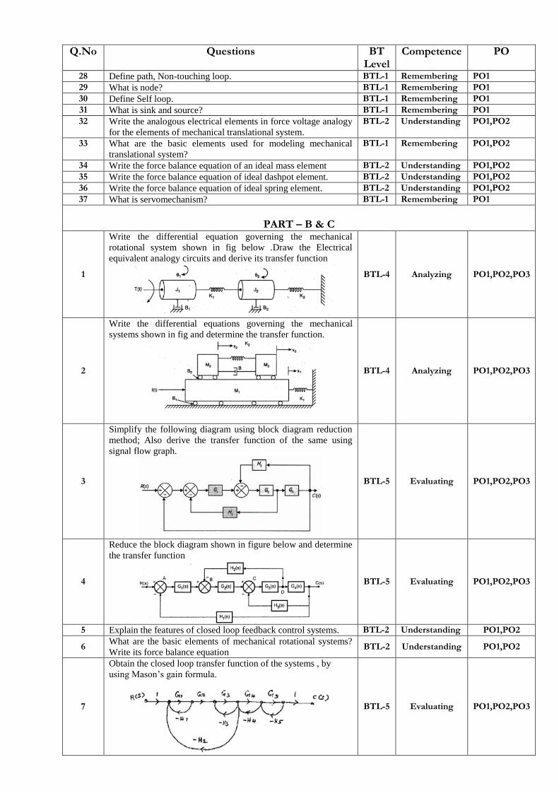
Write the differential equation governing the mechanical
rotational system shown in fig below .Draw the Electrical
equivalent analogy circuits and derive its transfer function
BTL-4 Analyzing PO1,PO2,PO3
2
Write the differential equations governing the mechanical
systems shown in fig and determine the transfer function.
BTL-4 Analyzing PO1,PO2,PO3
3
Simplify the following diagram using block diagram reduction
method; Also derive the transfer function of the same using
signal flow graph.
BTL-5 Evaluating PO1,PO2,PO3
4
Reduce the block diagram shown in figure below and determine
the transfer function
BTL-5 Evaluating PO1,PO2,PO3
5 Explain the features of closed loop feedback control systems. BTL-2 Understanding PO1,PO2
6 What are the basic elements of mechanical rotational systems?
Write its force balance equation BTL-2 Understanding PO1,PO2
7
Obtain the closed loop transfer function of the systems , by
using Mason‟s gain formula.
BTL-5 Evaluating PO1,PO2,PO3

8
Write down the differential equation for the given mechanical
system as shown in fig.(1) and derive its transfer function and
also draw the electrical equivalent analogous system
BTL-5 Evaluating PO1,PO2,PO3
9
Obtain the differential equation for the mechanical system
shown in fig below and obtain the force-voltage analogous and
force-current analogous.
BTL-5 Evaluating PO1,PO2,PO3
UNIT II TIME RESPONSE ANALYSIS Time response analysis - First Order Systems - Impulse and Step Response analysis of second order systems - Steady state errors – P, PI, PD and PID Compensation, Analysis using MATLAB
PART – A
CO Mapping : C214.2
Q.No Questions BT Level
Competence PO
1 Name the test signals used in control system. BTL-4 Analyzing PO1
2 What are generalized error coefficients? BTL-1 Remembering PO1,PO2
3 Define Steady state error. BTL-2 Understanding PO1,PO2
4 Draw the transfer function model for PID control? BTL-4 Analyzing PO2
5 List the time domain specifications BTL-1 Remembering PO1
6 What is the effect of PI controller on the system performance? BTL-2 Understanding PO1
7 How do you find the type of a system? BTL-2 Understanding PO1,PO2
8 What is steady state response? BTL-1 Remembering PO1
9 What is an order of a system BTL-1 Remembering PO1
10 Define Damping ratio. BTL-1 Remembering PO1
11 How a control system is classified depending on the value of
damping?
BTL-2 Understanding PO1,PO2
12 What are transient and steady state response of a control
system?
BTL-4 Analyzing PO1
13 Give the steady state errors to a various standard inputs for type
2 system
BTL-4 Analyzing PO1,PO2
14 List out the different frequency domain specifications? BTL-1 Remembering PO1
15 How the transient responses of a system with feedback differ to
that with feedback?
BTL-4 Analyzing PO1
16 Define type of a system. BTL-1 Remembering PO1
17 What are the type 0 and type 1 system? BTL-1 Remembering PO1
18 Define resonant Peak BTL-1 Remembering PO1
19 Define Resonant frequency BTL-1 Remembering PO1,PO2
20 Define Damping ratio BTL-1 Remembering PO1,PO2
21 Define Delay time BTL-1 Remembering PO1,PO2
22 Define Rise time BTL-1 Remembering PO1,PO2
23 Define peak time BTL-1 Remembering PO1,PO2
24 Define peak overshoot BTL-1 Remembering PO1,PO2

25 Define Settling time BTL-1 Remembering PO1,PO2
26 What is step signal BTL-1 Remembering PO1,PO2,PO3
27 What is ramp signal BTL-1 Remembering PO1,PO2,PO3
28 What is a parabolic signal? BTL-1 Remembering PO1,PO2,PO3
29 List the advantages of generalized error coefficients BTL-1 Remembering PO1
30 Mention the characteristics of PI controller. BTL-2 Understanding PO1
31 What is the need for a controller? BTL-2 Understanding PO1
32 What are the different types of controllers? BTL-2 Understanding PO1,PO2
33 What is proportional controller? BTL-1 Remembering PO1,PO2
34 What is PI controller? BTL-1 Remembering PO1,PO2
35 What is PD controller? BTL-1 Remembering PO1,PO2
36 What is the significance of integral controller and derivative
controller in a PID controller?
BTL-2 Understanding PO1,PO2
37 Why derivative controller is not used in control systems BTL-4 Analyzing PO1,PO2
38 What is the disadvantage in proportional controller? BTL-2 Understanding PO1,PO2
39 What is the effect of PD controller on system performance? BTL-2 Understanding PO1,PO2
40 What is the effect of PI controller on the system performance BTL-2 Understanding PO1,PO2
PART – B & C
1
A unity feedback control system is characterized by the
following open loop transfer function )6(
14)(
SS
SSG
Determine its transient response for unit step input and sketch
the response. Evaluate the maximum overshoot and the
corresponding peak time.
BTL-5 Evaluating PO1,PO2, PO3,PO4
2 State and explain the effects of P ,PI and PID controller on the
system dynamics.
BTL-4 Analyzing PO1,PO2
3
A unity feedback control system is characterized by the
following open loop transfer function )10(
)(
SS
KSG
Determine the gain K so that the system will have a damping
ration of 0.5 for this value of K. Determine settling time ,peak
overshoot and peak time for a unit step input.
BTL-5 Evaluating PO1,PO2, PO3,PO4
4 Derive the time domain specification of a second order
subjected to a step input. BTL-4 Analyzing
PO1,PO2, PO3,PO4
5
A unity feedback control system has a is characterized by the
following open loop transfer function 2)1(
)(S
KSSG
For
the input ttr 51)( Find the minimum value of K so that
the steady state error is less than 0.1.
BTL-5 Evaluating PO1,PO2, PO3,PO4
6
Determine the type and order of the system with following
transfer function.
1. )2)(3(
4)(
SS
SSG 2.
)12(
10)(
23
SSSG
BTL-4 Analyzing PO1,PO2, PO3,PO4
7
For a system whose )2)(1(
10)(
SSSSG Find the state
steady when it is subjected to input 25.121)( tttr
BTL-5 Evaluating PO1,PO2, PO3,PO4
8
The open loop transfer function of a unity feedback system is
given by )1(
)(
STS
KSG where K&T are positive
constants by what factor should be amplifier gain K be reduced
to that peak overshoot of unit step response of the system is
reduced from 75% to 25%.
BTL-5 Evaluating PO1,PO2, PO3,PO4
9 Derive an expression to find steady state error of a closed loop BTL-3 Applying PO1,PO2,

control system PO3,PO4
UNIT III FREQUENCY RESPONSE ANALYSIS
Frequency Response - Bode Plot, Polar Plot, Nyquist Plot - Frequency Domain specifications from the plots - Constant M and N Circles – Nichol‟s Chart - Use of Nichol‟s Chart in Control System Analysis. Series, Parallel, series-parallel Compensators - Lead, Lag, and Lead Lag Compensators, Analysis using MATLAB.
PART – A
CO Mapping : C214.3
Q.No Questions BT Level
Competence PO
1 What are the constant M and N circle? BTL-1 Remembering PO1 2 Why compensation is necessary for feedback control systems? BTL-2 Understanding PO1
3 Define Gain and Phase margin BTL-1 Remembering PO1,PO2
4 State the significance of Nichol‟s plot BTL-1 Remembering PO1,PO2
5 What is phase margin? BTL-1 Remembering PO1,PO2
6 What is series compensation? BTL-1 Remembering PO1
7 What are the frequency domain specifications? BTL-2 Understanding PO1,PO2
8 How phase margin determined from bode‟s plot? BTL-4 Analyzing PO1,PO2
9 Mention the need for lead compensation and lag compensation. BTL-4 Analyzing PO1,PO2
10 Define Phase cross over? BTL-1 Remembering PO1,PO2
11 Define Gain cross over? BTL-1 Remembering PO1,PO2
12 What is Bode plot? BTL-1 Remembering PO1,PO2
13 What are the main advantages of Bode plot? BTL-1 Remembering PO1,PO2
14 Define Corner frequency? BTL-1 Remembering PO1,PO2,PO3
15 Define Phase lag and phase lead? BTL-1 Remembering PO1,PO2,PO3
16 What are M circles? BTL-1 Remembering PO1,PO2,PO3
17 What is Nichols chart? BTL-1 Remembering PO1,PO2,PO3
18 What are two contours of Nichols chart? BTL-1 Remembering PO1,PO2,PO3
19 How is the Resonant Peak (Mr), resonant frequency (Wr), and
band width determined from Nichols chart? BTL-4 Analyzing
PO1,PO2,PO3
20 What are the advantages of Nichols chart? BTL-2 Understanding PO1,PO2,PO3
21 What are the three types of compensators? BTL-2 Understanding PO1,PO2
22 When is lag lead compensator is required BTL-2 Understanding PO1,PO2
23 What is a compensator? BTL-1 Remembering PO1,PO2
24 What is compensation and compensators? BTL-1 Remembering PO1,PO2
25 What are the effects of lag-lead compensators? BTL-2 Understanding PO1,PO2
26 List the advantages and disadvantages of phase lag network. BTL-1 Remembering PO1,PO2
27 What are the two types of compensation? BTL-2 Understanding PO1,PO2
28 What are the uses of lead compensator? BTL-2 Understanding PO1,PO2
29 What is the use of lag compensator? BTL-1 Remembering PO1,PO2
30 What is bandwidth? BTL-1 Remembering PO1,PO2,PO3
31 Define Gain and Phase margin. BTL-1 Remembering PO1,PO2,PO3
32 What is a lag lead compensator? BTL-1 Remembering PO1,PO2,PO3
33 What are the two situations in which compensation is required? BTL-3 Applying PO1,PO2
34 What are the observations that are made from the Bode‟s plot of
the lag compensated system? BTL-4 Analyzing
PO1,PO2,PO3
35 What are compensating networks? BTL-1 Remembering PO1,PO2,PO3
PART – B & C
1
A unity fed back control systems )10)(4(
)(
SSS
KSG
Draw the bode plot.
BTL-4 Analyzing PO1,PO2, PO3,PO4
2 The open loop transfer function of a unity feedback system is
)1()(
SS
KSG It is desired to have the velocity error
constant 1sec20 VK and phase margin as
40 Design a
lead compensator to meet the above specification.
BTL-6 Creating PO1,PO2, PO3,PO4
3 Analyze on Lead, Lag and Lag-Lead compensators with a neat
diagram also explain their importance. BTL-4 Analyzing
PO1,PO2, PO3,PO4
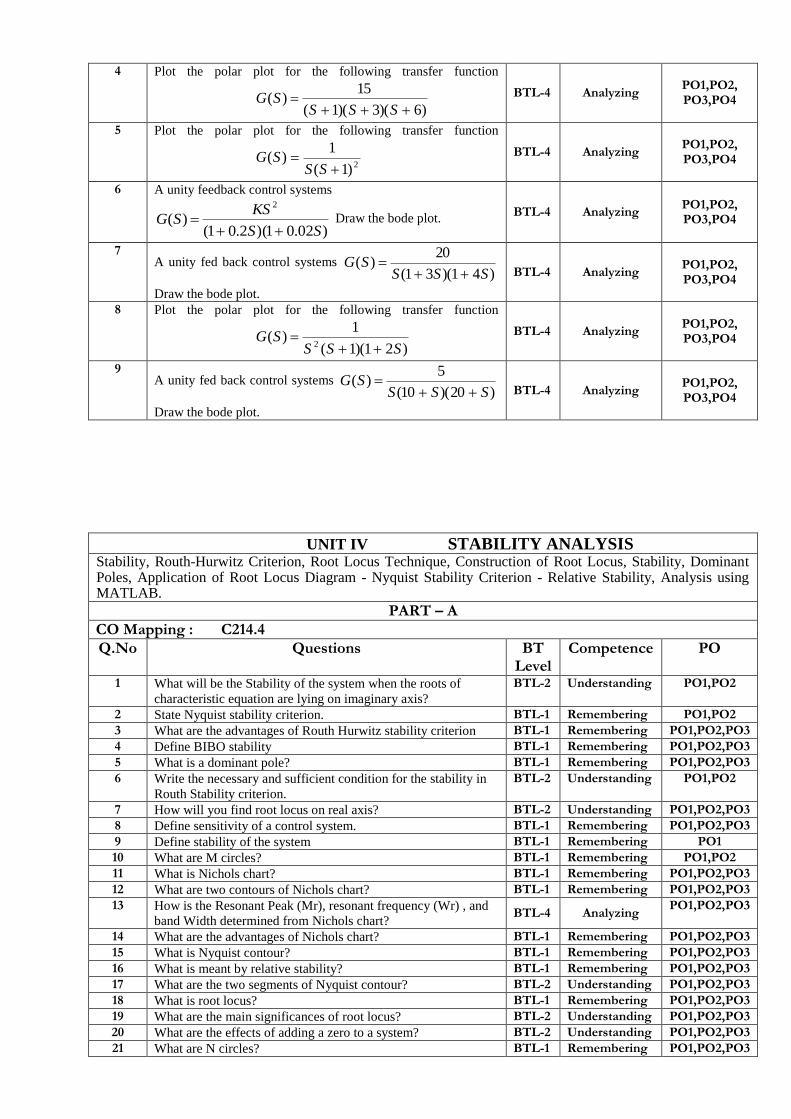
4 Plot the polar plot for the following transfer function
)6)(3)(1(
15)(
SSSSG BTL-4 Analyzing
PO1,PO2, PO3,PO4
5 Plot the polar plot for the following transfer function
2)1(
1)(
SSSG
BTL-4 Analyzing PO1,PO2, PO3,PO4
6 A unity feedback control systems
)02.01)(2.01()(
2
SS
KSSG
Draw the bode plot.
BTL-4 Analyzing PO1,PO2, PO3,PO4
7 A unity fed back control systems
)41)(31(
20)(
SSSSG
Draw the bode plot.
BTL-4 Analyzing PO1,PO2, PO3,PO4
8 Plot the polar plot for the following transfer function
)21)(1(
1)(
2 SSSSG
BTL-4 Analyzing
PO1,PO2, PO3,PO4
9 A unity fed back control systems
)20)(10(
5)(
SSSSG
Draw the bode plot.
BTL-4 Analyzing PO1,PO2, PO3,PO4
UNIT IV STABILITY ANALYSIS
Stability, Routh-Hurwitz Criterion, Root Locus Technique, Construction of Root Locus, Stability, Dominant Poles, Application of Root Locus Diagram - Nyquist Stability Criterion - Relative Stability, Analysis using MATLAB.
PART – A
CO Mapping : C214.4
Q.No Questions BT Level
Competence PO
1 What will be the Stability of the system when the roots of
characteristic equation are lying on imaginary axis?
BTL-2 Understanding PO1,PO2
2 State Nyquist stability criterion. BTL-1 Remembering PO1,PO2
3 What are the advantages of Routh Hurwitz stability criterion BTL-1 Remembering PO1,PO2,PO3
4 Define BIBO stability BTL-1 Remembering PO1,PO2,PO3
5 What is a dominant pole? BTL-1 Remembering PO1,PO2,PO3
6 Write the necessary and sufficient condition for the stability in
Routh Stability criterion.
BTL-2 Understanding PO1,PO2
7 How will you find root locus on real axis? BTL-2 Understanding PO1,PO2,PO3
8 Define sensitivity of a control system. BTL-1 Remembering PO1,PO2,PO3
9 Define stability of the system BTL-1 Remembering PO1
10 What are M circles? BTL-1 Remembering PO1,PO2
11 What is Nichols chart? BTL-1 Remembering PO1,PO2,PO3
12 What are two contours of Nichols chart? BTL-1 Remembering PO1,PO2,PO3
13 How is the Resonant Peak (Mr), resonant frequency (Wr) , and
band Width determined from Nichols chart? BTL-4 Analyzing
PO1,PO2,PO3
14 What are the advantages of Nichols chart? BTL-1 Remembering PO1,PO2,PO3
15 What is Nyquist contour? BTL-1 Remembering PO1,PO2,PO3
16 What is meant by relative stability? BTL-1 Remembering PO1,PO2,PO3
17 What are the two segments of Nyquist contour? BTL-2 Understanding PO1,PO2,PO3
18 What is root locus? BTL-1 Remembering PO1,PO2,PO3
19 What are the main significances of root locus? BTL-2 Understanding PO1,PO2,PO3
20 What are the effects of adding a zero to a system? BTL-2 Understanding PO1,PO2,PO3 21 What are N circles? BTL-1 Remembering PO1,PO2,PO3

22 What is the necessary condition for stability? BTL-2 Understanding PO1,PO2,PO3
23 What is limitedly stable system? BTL-1 Remembering PO1,PO2
24 Define parameter variations. BTL-1 Remembering PO1,PO2
25 How the roots of characteristic equation are related to stability? BTL-2 Understanding PO1,PO2,PO3
26 What is the relation between stability and coefficient of
characteristic polynomial? BTL-4 Analyzing
PO1
27 What will be the Stability of the system when the roots of
characteristic equation are lying on right half of the S-plane?
BTL-2 Understanding PO1,PO2
28 The addition of a pole will make a system more stable. Justify
your answer. BTL-5 Evaluating
PO1,PO2
29 What is centroid? How the centroid is calculated? BTL-1 Remembering PO1,PO2
30 Give the effect of addition of poles on the root locus. BTL-2 Understanding PO1,PO2
31 State the advantages of root locus method. BTL-1 Remembering PO1,PO2PO4
32 Define gain margin in Nyquist plot. BTL-1 Remembering PO1,PO2,PO3
PART – B & C
1 Sketch the root locus for
)4)(2(
)204()(
2
SS
SSKSG Find the
gain, K at the point where the locus crosses the imaginary axis.
BTL-4 Analyzing PO1,PO2, PO3,PO4
2
Draw the Nyquist plot for the system whose open loop transfer
function is )1)(110(
)1))051()(
SS
SSKSG Determine the range
of K for which closed loop system is stable.
BTL-4 Analyzing PO1,PO2, PO3,PO4
3 Define Stability. With an example explain the steps to be
followed for Routh - Hurwitz criterion. BTL-3 Applying
PO1,PO2, PO3,PO4
4
Determine the range of K for stability of unity feedback system
using Routh stability criterion whose transfer function
KSSSS
K
SR
SC
)2)(1()(
)(2
BTL-4 Analyzing PO1,PO2, PO3,PO4
5 Explain briefly about the steps to be followed to construct a root
locus plot of a given transfer function. BTL-6 Creating
PO1,PO2, PO3,PO4
6
Construct R-H criterion and determine the stability of a system
representing the characteristics equation
05322 2345 SSSSS .Comment on location of
the roots of the characteristics equation.
BTL-3 Applying PO1,PO2, PO3,PO4
7
Construct R-H criterion and determine the stability of a system
representing the characteristics equation
01616201282 23456 SSSSSS .Comment
on location of the roots of the characteristics equation.
BTL-3 Applying PO1,PO2, PO3,PO4
8
A unity feedback control system has an open loop transfer
function )134(
)(2
SSS
KSG Sketch the root locus. BTL-4 Analyzing
PO1,PO2, PO3,PO4
9 Describe the Nyquist contour and its various segments.
BTL-6 Creating PO1,PO2, PO3,PO4
UNIT V STATE VARIABLE ANALYSIS State space representation of Continuous Time systems – State equations – Transfer function from State
Variable Representation – Solutions of the state equations - Concepts of Controllability and Observability –
State space representation for Discrete time systems. Sampled Data control systems – Sampling Theorem –
Sampler & Hold – Open loop & Closed loop sampled data systems.
PART – A
CO Mapping : C214.5
Q.No Questions BT Level
Competence PO
1 Define state model of nth order system? BTL-1 Remembering PO1,PO2
2 What is meant by sampling theorem? BTL-1 Remembering PO1,PO2
3 What are the uses of sampled-data control systems? BTL-3 Applying PO1,PO2
4 List the main properties of state transition matrix. BTL-2 Understanding PO1,PO2
5 Define state and state variables? BTL-1 Remembering PO1,PO2
6 What is zero-order hold? BTL-1 Remembering PO1
7 What is state vector? BTL-1 Remembering PO1,PO2
8 What is state space? BTL-1 Remembering PO1,PO2
9 List the methods used to test the stability of discrete time
system.
BTL-1 Remembering PO1,PO2
10 Draw the Sampler and Hold circuit. BTL-4 Analyzing PO1,PO2
11 When a system is said to be controllable. BTL-2 Understanding PO1,PO2
12 Define sampled data system. BTL-1 Remembering PO1
13 What are sampling and sampler? BTL-1 Remembering PO1
14 What is periodic sampling? BTL-1 Remembering PO1
15 What is first order hold? BTL-1 Remembering PO1
16 What is acquisition time? BTL-1 Remembering PO1
17 Define aperture time. BTL-1 Remembering PO1
18 What is settling time? BTL-1 Remembering PO1,PO2
19 When a system is referred as sampled data control system. BTL-2 Understanding PO1,PO2
20 When a ZOH is used BTL-2 Understanding PO1
21 What is state variable? BTL-1 Remembering PO1,PO2
22 When a system is said to be observable. BTL-2 Understanding PO1,PO2
23 Give the state equation for observability. BTL-2 Understanding PO1,PO2
24 What is state transition matrix? BTL-1 Remembering PO1,PO2
25 Mention the need for state variables BTL-2 Understanding PO1,PO2
26 What is meant by quantization? BTL-1 Remembering PO1
27 What is meant by sampled data controlled system? BTL-1 Remembering PO1
28 What are the advantages of state space representation? BTL-2 Understanding PO1
29 Define state equation? BTL-1 Remembering PO1,PO2
30 Give the concept of controllability. BTL-3 Applying PO1,PO2
31 What are sampler and hold circuits? BTL-1 Remembering PO1
PART – B & C
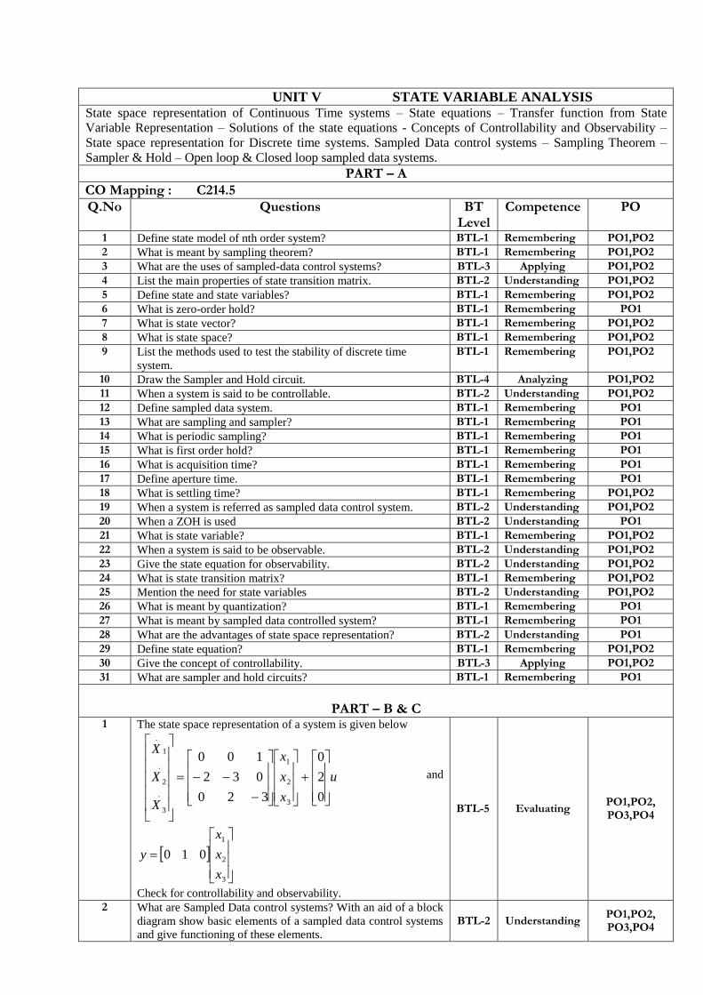
1 The state space representation of a system is given below
u
x
x
x
X
X
X
0
2
0
320
032
100
3
2
1
.
3
.
2
1
.
and
3
2
1
010
x
x
x
y
Check for controllability and observability.
BTL-5 Evaluating PO1,PO2, PO3,PO4
2 What are Sampled Data control systems? With an aid of a block
diagram show basic elements of a sampled data control systems
and give functioning of these elements.
BTL-2 Understanding PO1,PO2, PO3,PO4
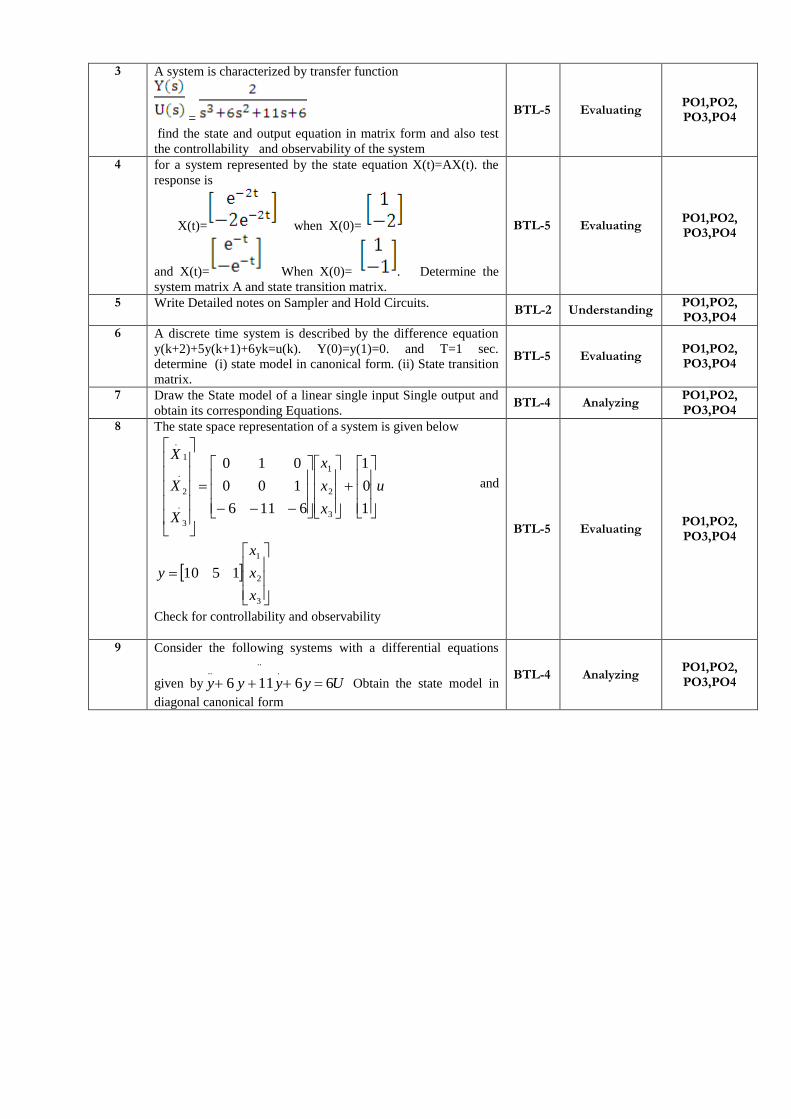
3 A system is characterized by transfer function
=
find the state and output equation in matrix form and also test
the controllability and observability of the system
BTL-5 Evaluating PO1,PO2, PO3,PO4
4 for a system represented by the state equation X(t)=AX(t). the
response is
X(t)= when X(0)=
and X(t)= When X(0)= . Determine the
system matrix A and state transition matrix.
BTL-5 Evaluating PO1,PO2, PO3,PO4
5 Write Detailed notes on Sampler and Hold Circuits. BTL-2 Understanding
PO1,PO2, PO3,PO4
6 A discrete time system is described by the difference equation
y(k+2)+5y(k+1)+6yk=u(k). Y(0)=y(1)=0. and T=1 sec.
determine (i) state model in canonical form. (ii) State transition
matrix.
BTL-5 Evaluating PO1,PO2, PO3,PO4
7 Draw the State model of a linear single input Single output and
obtain its corresponding Equations. BTL-4 Analyzing
PO1,PO2, PO3,PO4
8 The state space representation of a system is given below
u
x
x
x
X
X
X
1
0
1
6116
100
010
3
2
1
.
3
.
2
1
.
and
3
2
1
1510
x
x
x
y
Check for controllability and observability
BTL-5 Evaluating PO1,PO2, PO3,PO4
9 Consider the following systems with a differential equations
given by Uyyyy 66116
.....
Obtain the state model in
diagonal canonical form
BTL-4 Analyzing PO1,PO2, PO3,PO4

UNIT I CONTROL SYSTEM MODELING Basic Elements of Control System – Open loop and Closed loop systems - Differential equation - Transfer
function, Modeling of Electric systems, Translational and rotational mechanical systems - Block diagram
reduction Techniques - Signal flow graph PART – A
1. Give the comparison between open loop and closed loop System. (Nov/Dec 2017) (April/May2017) (May/June
2016)
Open Loop System Closed Loop System
i) The control system in which the output quantity has no effect upon the input quantity is called open loop control system. This means that the output is not feedback to the input for correction.
i) The control system in which the output has an effect upon the input quantity so as to maintain the desired output value is called closed loop control system.
ii) Inaccurate& Reliable ii) Inaccurate &Reliable
iii) Simple &Economical iii) Complex & Costlier
iv) Generally stable iv) Great efforts are needed to design a stable
system.
v) The changes in output due to external disturbances are not
corrected automatically.
v) The changes in output due to external
disturbances are corrected automatically.
2. Write Masons Gain formula. (April/May 2017) (April/May2015) ( May /June 2016) The overall system transfer function C(S)/R(S) is referrred as Mason‟s gain formula.It is given by Overall T.F=∑(TK∆K)
/∆ , Where K = Number of forward paths , TK = Gain of kth
forward path , ∆ =system determinant to be calculated as:
∆=1-(∑all individual feedback loop gains (including self loops)+ (∑Gain x gain product of all possible combinations of
two non-touching loops)- (∑Gain xGainx Gain product of all possible combinations of two non-touching loops)+….. ∆K
=value of above ∆ for all loop gains and associated products which are touching to the kth forward path.
3. Define transfer function. (Nov/Dec 2017)(Nov/Dec 2013) The T.F of a system is defined as the ratio of the Laplace transform of output to Laplace transform of input with zero initial conditions.
4. What is control system? (Nov/Dec 2016)
A System consists of a number of components connected together to perform a specific function. In a system when the
output quantity is controlled by varying the input quantity then the system is called control system.
5. List the basic elements of translational mechanical systems. (Nov/Dec 2016)
There are three fundamental physical elements that make up translating mechanical system: inertia elements, springs and
friction elements.
6. What are the advantages of the closed loop control system? ( Nov/Dec 2015)
Advantages:
Accuracy: They are more accurate than open loop system due to their complex construction. They are equally accurate
and are not disturbed in the presence of non-linearity. Noise reduction ability: Since they are composed of a feedback
mechanism, so they clear out the errors between input and output signals, and hence remain unaffected to the external
noise sources.
7. What is block diagram? ( Nov/Dec 2015)
A block diagram of a system is a pictorial representation of the functions performed by each component of the system and
shows the flow of signals. The basic elements of block diagram are block, branch point and summing point.
8. What are the elements of block diagram? ( Nov/Dec 2015)
The elements of block diagram are
Block
Summing point
Branch point
9. Give some examples of control system.
The examples of control systems are
Temperature control system
Traffic control system
Numerical control system
Position control system
10. What are the two major types of control system?
The two major types of control system are open loop and closed loop.
11. Define open loop control system. (May/June 2007)
The control system in which the output quantity has no effect upon the input quantity are called open loop control system.
This means that the output is not feedback to the input for correction.
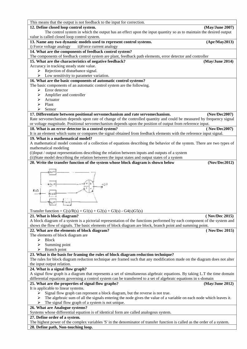
12. Define closed loop control system. (May/June 2007)
The control system in which the output has an effect upon the input quantity so as to maintain the desired output
value is called closed loop control system.
13. Name any two dynamic models used to represent control systems. (Apr/May2013)
i) Force voltage analogy ii)Force current analogy
14. What are the components of feedback control system?
The components of feedback control system are plant, feedback path elements, error detector and controller
15. What are the characteristics of negative feedback? (May/June 2014)
Accuracy in tracking steady state value.
Rejection of disturbance signal.
Low sensitivity to parameter variation.
16. What are the basic components of automatic control systems?
The basic components of an automatic control system are the following.
Error detector
Amplifier and controller
Actuator
Plant
Sensor
17. Differentiate between positional servomechanism and rate servomechanism. (Nov/Dec2007)
Rate servomechanism depends upon rate of change of the controlled quantity and could be measured by frequency signal
or voltage magnitude. Positional servomechanism depends upon the position of output from reference input.
18. What is an error detector in a control system? ( Nov/Dec2007)
It is an element which sums or compares the signal obtained from feedback elements with the reference input signal.
19. What is a mathematical model?
A mathematical model consists of a collection of equations describing the behavior of the system. There are two types of
mathematical modeling
(i)Input / output representations describing the relation between inputs and outputs of a system
(ii)State model describing the relation between the input states and output states of a system
20. Write the transfer function of the system whose block diagram is shown below (Nov/Dec2012)
Transfer function = C(s)/R(s) = G1(s) + G2(s) + G3(s) - G4(s)G5(s)
21. What is block diagram? ( Nov/Dec 2015) A block diagram of a system is a pictorial representation of the functions performed by each component of the system and
shows the flow of signals. The basic elements of block diagram are block, branch point and summing point.
22. What are the elements of block diagram? ( Nov/Dec 2015)
The elements of block diagram are
Block
Summing point
Branch point
23. What is the basis for framing the rules of block diagram reduction technique?
The rules for block diagram reduction technique are framed such that any modification made on the diagram does not alter
the input output relation.
24. What is a signal flow graph?
A signal flow graph is a diagram that represents a set of simultaneous algebraic equations. By taking L.T the time domain
differential equations governing a control system can be transferred to a set of algebraic equations in s-domain
25. What are the properties of signal flow graphs? (May/June 2012)
It is applicable to linear systems.
Signal flow graph can represent a block diagram, but the reverse is not true.
The algebraic sum of all the signals entering the node gives the value of a variable on each node which leaves it.
The signal flow graph of a system is not unique.
26. What are Analogue systems?
Systems whose differential equation is of identical form are called analogous system.
27. Define order of a system.
The highest power of the complex variables 'S' in the denominator of transfer function is called as the order of a system.
28. Define path, Non-touching loop.

Path: It is the journey from one node to any other node in the direction of branch arrow
Non-touching loop: Loops are said to be non-touching if they do not possess any common node.
29. What is node?
Node is a system variable which is equal to sum of all incoming signals.
30. Define Self loop.
Self-loop: A path starting from one node and terminates at same node without crossing any other node even once.
31. What is sink and source?
Source is the input node in the signal flow graph and it has only outgoing branches. Sink is an output node in the signal
flow graph and it has only incoming branches.
32. Write the analogous electrical elements in force voltage analogy for the elements of mechanical translational
system.
33. What are the basic elements used for modeling mechanical translational system?
Mass, spring and dashpot.
34. Write the force balance equation of an ideal mass element
35. Write the force balance equation of ideal dashpot element.
36. Write the force balance equation of ideal spring element.
37 . What is servomechanism?
Servomechanism is a feedback control system in which the output is Mechanical position (or time derivatives of position
velocity and acceleration.
PART – B & C
1.Write the differential equation governing the mechanical rotational system shown in fig below .Draw the
Electrical equivalent analogy circuits and derive its transfer function (Nov/Dec 2016)

Ref: Control Systems Engineering By Dr.S.Palani, Pg.No: 2.42
2 Write the differential equations governing the mechanical systems shown in fig and determine the transfer
function. (Nov/Dec 2017)
Ref: Control Systems Engineering By Dr.S.Palani, Pg.No: 2.43
3 Simplify the following diagram using block diagram reduction method; Also derive the transfer function of the
same using signal flow graph. (April/May 2017)
Ref: Control Systems Engineering By S. K. Bhattacharya, Pg.No: 55
4. Reduce the block diagram shown in figure below and determine the transfer function. (Nov/Dec 2016)
Ref: Control Systems Engineering By Bakshi, Pg.No: 5.72
5. Explain the features of closed loop feedback control systems. . (April/May 2015)
Ref: Control Systems Engineering By Nagoorkani, Pg.No: 74
6. What are the basic elements of mechanical rotational systems? Write its force balance equation. (May/June2016)
Ref: Control Systems Engineering By Nagoorkani, Pg.No: 76
7. Obtain the closed loop transfer function of the systems, by using Mason’s gain formula. (Nov/Dec 2017)
Ref: Control Systems Engineering By Nagoorkani, Pg.No: 117
8.Write down the differential equation for the given mechanical system as shown in fig.(1) and derive its transfer
function and also draw the electrical equivalent analogous system (April/May 2015)

Ref: Control Systems Engineering By Nagoorkani, Pg.No: 85
9. Obtain the differential equation for the mechanical system shown in fig below and obtain the force-voltage
analogous and force-current analogous. (Nov/Dec 2015)
Ref: Control Systems Engineering By Nagoorkani, Pg.No: 86
UNIT II TIME RESPONSE ANALYSIS Time response analysis - First Order Systems - Impulse and Step Response analysis of second order systems - Steady state errors – P, PI, PD and PID Compensation, Analysis using MATLAB
PART – A 1. Name the test signals used in control system. ( Nov/Dec 2017) (May/June 2016)(Nov/Dec 2015)
Step signal, unit step signal
Ramp signal, unit Ramp signal Parabolic signal, unit parabolic signal
Impulse signal Sinusoidal signal 2. What are generalized error coefficients? ( Nov/Dec 2017)
They are the coefficients of generalized series. The generalized error series is given by e(t) = C0r(t) + C1dr(t)/dt + ( C2 /
2! ) dr2(t)/dt2 + ………….. + (Cn / n!) drn(t)/dtn… The coefficients C0, C1, C2,…,Cn are called generalized error
coefficients or dynamic error coefficients.
3. Define Steady state error. (Nov/Dec 2016)(April/May 2017)(Nov/Dec 2015) The steady state error is defined as the value of error as time tends to infinity. The steady state error is a measure of system
accuracy. These error arise from the nature of inputs, type of system and from non linearity of system component.
4. Draw the transfer function model for PID control? ( April/May 2017)
5. List the time domain specifications. (Nov/Dec 2016)
The time domain specifications
Delay time
Rise time
Peak time
Peak overshoot

6. What is the effect of PI controller on the system performance?(May/June 2016)
The PI controller increases the order of the system by one, which results in reducing the steady state error .But the system
becomes less stable than the original system.
7. How do you find the type of a system?(April/May 2015)
Type of a system is given by number of poles of loop transfer function lying at origin of S- Plane.
8. What is steady state response?
The steady state response is the response of the system when it approaches infinity.
9. What is an order of a system. ( Nov/Dec 2006)( April/May 2008) The order of a system is the order of the differential equation governing the system. The order of the system can be
obtained from the transfer function of the given system.
10. Define Damping ratio.
Damping ratio is defined as the ratio of actual damping to critical damping.
11. How a control system is classified depending on the value of damping?(May/June 2011)
Critically damped system
Over damped system
Naturally damped system
Under damped system
12. What are transient and steady state response of a control system?(Nov/Dec 2012)
The transient response is the response of a system as a function of time. Whenever there is an input change, the system
cannot respond immediately. It requires sometime. This time gap is referred as transient response.The steady state
response is the response of the system when it approaches infinity.
13. Give the steady state errors to a various standard inputs for type 2 system(May/June 2013)
ess = A/Kp
14. List out the different frequency domain specifications?(May/June 2007) The frequency domain specification are Resonant peak.
Resonant frequency.
Bandwidth
Cut-off rate
Gain margin
Phase margin
15. How the transient responses of a system with feedback differ to that with feedback?(Nov/Dec 2007)
The transient response is the response of a system as a function of time. Whenever there is a input change, the system
cannot respond immediately. It requires sometime. This time gap is referred as transient response. A feedback control
system has the inherent capability that its parameters can be adjusted to alter both its transient and steady state behavior.
16. Define type of a system.(April/May 2008) The number of poles of the loop transfer function lying at the origin decides the type number of the system.
17. What are the type 0 and type 1 system?(May/June 2014)
Type 0 System are systems whose no.of poles at the origin(N)=0.
Type 1 System are systems whose no.of poles at the origin(N)=0.
18. Define resonant Peak
The maximum value of the magnitude of closed loop transfer function is called resonant peak 19. Define Resonant frequency The frequency at which resonant peak occurs is called resonant frequency.
20. Define Damping ratio Damping ratio is defined as the ratio of actual damping to critical damping.
21. Define Delay time The time taken for response to reach 50% of final value for the very first time is delay time.
22. Define Rise time(May/June 2014) The time taken for response to raise from 0% to 100% for the very first time is rise time.
23. Define peak time(Nov/Dec 2012) The time taken for the response to reach the peak value for the first time is peak time. With reference to time response of a control system, define peak time The time taken for the response to reach the peak value for the first time is peak time.
24.Define peak overshoot(Nov/Dec 2010) Peak overshoot is defined as the ratio of maximum peak value measured from the Maximum value to final value.
25.Define Settling time
Settling time is defined as the time taken by the response to reach and stay within specified Error.
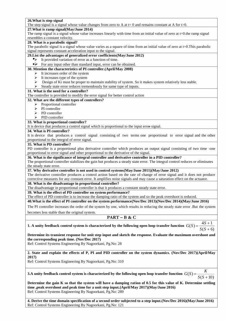
26.What is step signal The step signal is a signal whose value changes from zero to A at t= 0 and remains constant at A for t>0.
27.What is ramp signal(May/June 2014) The ramp signal is a signal whose value increases linearly with time from an initial value of zero at t=0.the ramp signal resembles a constant velocity.
28. What is a parabolic signal? The parabolic signal is a signal whose value varies as a square of time from an initial value of zero at t=0.This parabolic signal represents constant acceleration input to the signal.
29.List the advantages of generalized error coefficients(May/June 2012) It provided variation of error as a function of time.
For any input other than standard input, error can be obtained. 30. Mention the characteristics of PI controller.(April/May 2008)
It increases order of the system
It increases type of the system
Design of Ki must be proper to maintain stability of system. So it makes system relatively less stable.
Steady state error reduces tremendously for same type of inputs.
31. What is the need for a controller?
The controller is provided to modify the error signal for better control action
32. What are the different types of controllers?
Proportional controller
PI controller
PD controller
PID controller
33. What is proportional controller?
It is device that produces a control signal which is proportional to the input error signal.
34. What is PI controller?
It is device that produces a control signal consisting of two terms one proportional to error signal and the other
proportional to the integral of error signal.
35. What is PD controller? PD controller is a proportional plus derivative controller which produces an output signal consisting of two time -one proportional to error signal and other proportional to the derivative of the signal.
36. What is the significance of integral controller and derivative controller in a PID controller? The proportional controller stabilizes the gain but produces a steady state error. The integral control reduces or eliminates the steady state error.
37. Why derivative controller is not used in control systems(May/June 2011)(May/June 2012) The derivative controller produces a control action based on the rate of change of error signal and it does not produce corrective measures for any constant error. It amplifies noise signals and may cause a saturation effect on the actuator.
38. What is the disadvantage in proportional controller?
The disadvantage in proportional controller is that it produces a constant steady state error.
39. What is the effect of PD controller on system performance? The effect of PD controller is to increase the damping ratio of the system and so the peak overshoot is reduced.
40.What is the effect of PI controller on the system performance(Nov/Dec 2013)(Nov/Dec 2014)(May/June 2016)
The PI controller increases the order of the system by one, which results in reducing the steady state error .But the system
becomes less stable than the original system.
PART – B & C
1. A unity feedback control system is characterized by the following open loop transfer function )6(
14)(
SS
SSG
Determine its transient response for unit step input and sketch the response. Evaluate the maximum overshoot and
the corresponding peak time. (Nov/Dec 2017)
Ref: Control Systems Engineering By Nagoorkani, Pg.No: 28
2. State and explain the effects of P, PI and PID controller on the system dynamics. (Nov/Dec 2017)(April/May
2017)
Ref: Control Systems Engineering By Nagoorkani, Pg.No: 310
3.A unity feedback control system is characterized by the following open loop transfer function )10(
)(
SS
KSG
Determine the gain K so that the system will have a damping ration of 0.5 for this value of K. Determine settling
time ,peak overshoot and peak time for a unit step input.(April/May 2017)(May/June 2016)
Ref: Control Systems Engineering By Nagoorkani, Pg.No: 289
4. Derive the time domain specification of a second order subjected to a step input.(Nov/Dec 2016)(May/June 2016)
Ref: Control Systems Engineering By Nagoorkani, Pg.No: 121
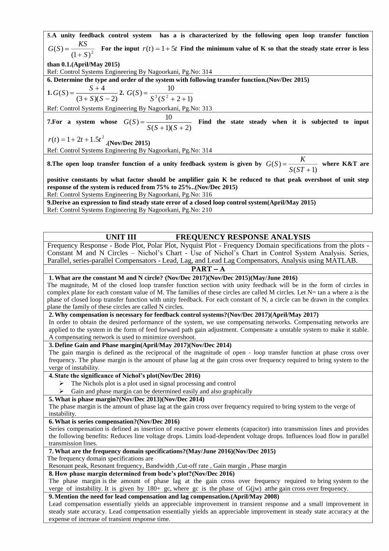
5.A unity feedback control system has a is characterized by the following open loop transfer function
2)1()(
S
KSSG
For the input ttr 51)( Find the minimum value of K so that the steady state error is less
than 0.1.(April/May 2015)
Ref: Control Systems Engineering By Nagoorkani, Pg.No: 314
6. Determine the type and order of the system with following transfer function.(Nov/Dec 2015)
1.)2)(3(
4)(
SS
SSG 2.
)12(
10)(
23
SSSG
Ref: Control Systems Engineering By Nagoorkani, Pg.No: 313
7.For a system whose )2)(1(
10)(
SSSSG Find the state steady when it is subjected to input
25.121)( tttr .(Nov/Dec 2015)
Ref: Control Systems Engineering By Nagoorkani, Pg.No: 314
8.The open loop transfer function of a unity feedback system is given by )1(
)(
STS
KSG where K&T are
positive constants by what factor should be amplifier gain K be reduced to that peak overshoot of unit step
response of the system is reduced from 75% to 25%..(Nov/Dec 2015)
Ref: Control Systems Engineering By Nagoorkani, Pg.No: 316
9.Derive an expression to find steady state error of a closed loop control system(April/May 2015)
Ref: Control Systems Engineering By Nagoorkani, Pg.No: 210
UNIT III FREQUENCY RESPONSE ANALYSIS
Frequency Response - Bode Plot, Polar Plot, Nyquist Plot - Frequency Domain specifications from the plots - Constant M and N Circles – Nichol‟s Chart - Use of Nichol‟s Chart in Control System Analysis. Series, Parallel, series-parallel Compensators - Lead, Lag, and Lead Lag Compensators, Analysis using MATLAB.
PART – A
1. What are the constant M and N circle? (Nov/Dec 2017)(Nov/Dec 2015)(May/June 2016) The magnitude, M of the closed loop transfer function section with unity feedback will be in the form of circles in complex plane for each constant value of M. The families of these circles are called M circles. Let N= tan a where a is the phase of closed loop transfer function with unity feedback. For each constant of N, a circle can be drawn in the complex plane the family of these circles are called N circles.
2. Why compensation is necessary for feedback control systems?(Nov/Dec 2017)(April/May 2017)
In order to obtain the desired performance of the system, we use compensating networks. Compensating networks are
applied to the system in the form of feed forward path gain adjustment. Compensate a unstable system to make it stable.
A compensating network is used to minimize overshoot.
3. Define Gain and Phase margin(April/May 2017)(Nov/Dec 2014)
The gain margin is defined as the reciprocal of the magnitude of open - loop transfer function at phase cross over
frequency. The phase margin is the amount of phase lag at the gain cross over frequency required to bring system to the
verge of instability.
4. State the significance of Nichol’s plot(Nov/Dec 2016)
The Nichols plot is a plot used in signal processing and control
Gain and phase margin can be determined easily and also graphically
5. What is phase margin?(Nov/Dec 2013)(Nov/Dec 2014) The phase margin is the amount of phase lag at the gain cross over frequency required to bring system to the verge of instability.
6. What is series compensation?(Nov/Dec 2016) Series compensation is defined as insertion of reactive power elements (capacitor) into transmission lines and provides the following benefits: Reduces line voltage drops. Limits load-dependent voltage drops. Influences load flow in parallel transmission lines.
7. What are the frequency domain specifications?(May/June 2016)(Nov/Dec 2015) The frequency domain specifications are Resonant peak, Resonant frequency, Bandwidth ,Cut-off rate , Gain margin , Phase margin
8. How phase margin determined from bode’s plot?(Nov/Dec 2016)
The phase margin is the amount of phase lag at the gain cross over frequency required to bring system to the
verge of instability. It is given by 180+ gc, where gc is the phase of G(jw) atthe gain cross over frequency.
9. Mention the need for lead compensation and lag compensation.(April/May 2008)
Lead compensation essentially yields an appreciable improvement in transient response and a small improvement in
steady state accuracy. Lead compensation essentially yields an appreciable improvement in steady state accuracy at the
expense of increase of transient response time.

10.Define Phase cross over?
The frequency at which, the phase of open loop transfer functions is called phase cross over frequency wpc.
11.Define Gain cross over? The gain cross over frequency w gc is the frequency at which the magnitude of the open loop transfer function is unity.
12.What is Bode plot? The Bode plot is the frequency response plot of the transfer function of a system. A Bode plot consists of two graphs. One is the plot of magnitude of sinusoidal transfer function versus log w.The other is a plot of the phase angle of a sinusoidal function versus log w.
13.What are the main advantages of Bode plot? The main advantages are: Multiplication of magnitude can be in to addition. A simple method for sketching an approximate log curve is available. It is based on asymptotic approximation. Such approximation is sufficient if rough information on the frequency
response characteristic is needed. The phase angle curves can be easily drawn if a template for the phase angle curve of 1+ jw is available.
14.Define Corner frequency?(May/June 2014) The frequency at which the two asymptotic meet in a magnitude plot is called corner frequency.
15.Define Phase lag and phase lead? A negative phase angle is called phase lag. A positive phase angle is called phase lead
16.What are M circles? The magnitude of closed loop transfer function with unit feed back can be shown to be in the every value of M. These circles are called M circles.
17.What is Nichols chart?
The chart consisting if M & N loci in the log magnitude versus phase diagram is called Nichols chart.
18.What are two contours of Nichols chart? Nichols chart of M and N contours, superimposed on ordinary graph. The M contours are the magnitude of closed loop system in decibels and the N contours are the phase angle locus of closed loop system.
19.How is the Resonant Peak (Mr), resonant frequency (Wr), and band width determined from Nichols chart? The resonant peak is given by the value of .contour which is tangent to G(jw ) locus. The resonant frequency is given by the frequency of G(jw) at the tangency point. The bandwidth is given by frequency corresponding to the intersection point of G(jw ) and 3dBM-contour.
20.What are the advantages of Nichols chart?(April/May 2015) The advantages are: It is used to find the closed loop frequency response from pen loop frequency response. Frequency domain specifications can be determined from Nichols chart. The gain of the system can be adjusted to satisfy the given specification.
21.What are the three types of compensators? Lag compensator
Lead compensator Lag-Lead compensator
22.When is lag lead compensator is required The lag lead compensator is required when both the transient and steady state response of a system has to be improved
23.What is a compensator? A device inserted into the system for the purpose of satisfying the specifications is called as a compensator.
24.What is compensation and compensators?(May/June 2007) The compensation is the design procedure in which the system behavior is altered to meet the desired specification, by introducing additional device called compensator.
25.What are the effects of lag-lead compensators?(May/June 2007)
Increases bandwidth and speeds up response
Decreases maximum overshoot
Increases low frequency gain and improves steady state accuracy of the system
26.List the advantages and disadvantages of phase lag network.(April/May 2015)
The Phase lag compensator helps to improve the steady-state error of the system. The poles of the lag compensator should
be very close together to help prevent the poles of the system from shifting right, and therefore reducing system stability.
27.What are the two types of compensation?
The Phase lag compensator helps to improve the steady-state error of the system. The poles of the lag compensator should
be very close together to help prevent the poles of the system from shifting right, and therefore reducing system stability.
28.What are the uses of lead compensator?
Speeds up the transient response Increases the margin of stability of a system Increases the system error constant to a limited extent.
29.What is the use of lag compensator?
Improve the steady state behavior of a system, while nearly preserving its transient response.
30.What is bandwidth? The bandwidth is the range of frequencies for which the system gain Is more than 3 dbB. The bandwidth is a measure of

the ability of a feedback system to reproduce the input signal, noise rejection characteristics and rise time.
31.Define Gain and Phase margin.(Nov/Dec 2014) The gain margin is defined as the reciprocal of the magnitude of open - loop transfer function at phase cross over frequency. The phase margin is the amount of phase lag at the gain cross over frequency required to bring system to the verge of instability.
32.What is a lag lead compensator? When both the transient and steady state response require improvement lag lead compensator is required. This is basically a lag lead compensator connected in series.
33.What are the two situations in which compensation is required? There are two situations in which compensation is required: The system is absolutely unstable and the compensation is required to stabilize it as well as to achieve a specified performance. The system is stable but the compensation is required to obtain the desired performance.
34.What are the observations that are made from the Bode’s plot of the lag compensated system? The cross over frequency is reduced. The high frequency end of the lag-magnitude plot has been raised up by a dB gain of 20log (1/a).
35.What are compensating networks? The compensator is a physical device. It may be an electrical network, mechanical unit pneumatic, hydraulic or combinations of various types. The commonly used electrical compensating networks are Lead network or Lead compensator Lag network or Lag compensator
Lag-Lead network or Lag-Lead compensator.
PART – B & C
1. A unity fed back control systems )10)(4(
)(
SSS
KSG Draw the bode plot.(Nov/Dec 2017)
Ref :Control systems Engineering by Nagoorkani ,Pg.No:370
2. The open loop transfer function of a unity feedback system is )1(
)(
SS
KSG It is desired to have the velocity
error constant 1sec20 VK and phase margin as
40 Design a lead compensator to meet the above
specification.(Nov/Dec 2017)
Ref :Control systems Engineering by Nagoorkani ,Pg.No:378
3. Analyze on Lead, Lag and Lag-Lead compensators with a neat diagram also explain their importance.
Ref :Control systems Engineering by Nagoorkani ,Pg.No:410
4. Plot the polar plot for the following transfer function )6)(3)(1(
15)(
SSSSG
(Nov/Dec 2017)(April/May 2017)
Ref :Control systems Engineering by Nagoorkani ,Pg.No:350
5.Plot the polar plot for the following transfer function 2)1(
1)(
SSSG (Nov/Dec 2016)
Ref :Control systems Engineering by Nagoorkani ,Pg.No:353
6.A unity feedback control systems )02.01)(2.01(
)(2
SS
KSSG
Draw the bode plot.(May/June 2016)
Ref :Control systems Engineering by Nagoorkani ,Pg.No:375
7.A unity fed back control systems )41)(31(
20)(
SSSSG
Draw the bode plot.(Nov/Dec 2015)
Ref :Control systems Engineering by Nagoorkani ,Pg.No:376
8.Plot the polar plot for the following transfer function )21)(1(
1)(
2 SSSSG
(Nov/Dec 2015)
Ref :Control systems Engineering by Nagoorkani ,Pg.No:353
9.A unity fed back control systems )20)(10(
5)(
SSSSG
Draw the bode plot. (April/May 2015)
Ref :Control systems Engineering by Nagoorkani ,Pg.No:375

UNIT IV STABILITY ANALYSIS
Stability, Routh-Hurwitz Criterion, Root Locus Technique, Construction of Root Locus, Stability, Dominant Poles, Application of Root Locus Diagram - Nyquist Stability Criterion - Relative Stability, Analysis using MATLAB.
PART – A
1. 1. What will be the Stability of the system when the roots of characteristic equation are lying on imaginary
axis?(Nov/Dec 2017)
If the roots of characteristic equation lie on imaginary axis, then the Stability of the system is oscillatory. 2. State Nyquist stability criterion. (Nov/Dec 2017) ( Nov/Dec 2015) (April/May 2017)
If the Nyquist plot of the open loop transfer function G(s) corresponding to the Nyquist control in the S-plane
encircles the critical point –1+j0 in the counter clockwise direction as many times as the number of right half
S-plane poles of G(s), the closed loop system is stable. 2. 3. What are the advantages of Routh Hurwitz stability criterion(April/May 2017)
Stability can be judged without solving the characteristic equation.
Less calculation time.
The number of roots in RHP can be found in the case of the unstable condition.
The range of value of K for system stability can be calculated.
Intersection point with the jw-axis can be calculated.
The frequency of oscillation at steady-state is calculated.
4. Define BIBO stability(Nov/Dec 2016)
A linear relaxed system is said to have BIBO stability if every bounded (finite) input results in a bounded
(finite) output. 3. 5. What is a dominant pole?(Nov/Dec 2016)(Nov/Dec 2015)
The dominant pole is an air of complex conjugate pair which decides the transient response of the system. 4. 6. Write the necessary and sufficient condition for the stability in Routh Stability criterion.(May/June 2016)
The necessary and sufficient condition for stability is that all of the elements in the first column of the Routh
array should be positive. 5. 7. How will you find root locus on real axis?(May/June 2016)
On the real axis, for K > 0, the root locus exist to the left of an odd number of real axis, fi- nite open-loop poles
and/or finite open loop zeros. 6. 8. Define sensitivity of a control system.
7. An effect in the system performance due to parameter variations can be studied mathematically defining
the tern sensitivity of a control system. The change in particular variable due to parameter can be
expressed in terms of sensitivity. 8. 9 .Define stability of the system(May/June 2011)
9. A linear time- invariant system is stable if the following two notions of system stability are satisfied.
10. When the system is by a bounded input, the output is bounded. 2. In the absence of the input, the output tends
towards zero irrespective of initial conditions
11. 10.What are M circles?
12. The magnitude of closed loop transfer function with unit feedback can be shown to be in the for every value if
M. These circles are called M circles
13. 11.What is Nichols chart?
The chart consisting if M & N loci in the log magnitude versus phase diagram is called Nichols chart. 14. 12.What are two contours of Nichols chart?
Nichols chart of M and N contours, superimposed on ordinary graph. The M contours are the magnitude of
closed loop system in decibels and the N contours are the phase angle locus of closed loop system. 13. How is the Resonant Peak (Mr), resonant frequency (Wr) , and band Width determined from Nichols chart?
The resonant peak is given by the value of ì.contour which is tangent to G(jw ) locus.
The resonant frequency is given by the frequency of G(jw ) at the tangency point.
The bandwidth is given by frequency corresponding to the intersection point of G(jw ) and –3dB M-
contour. 14. What are the advantages of Nichols chart?(April/May 2010)
The advantages are:
It is used to find the closed loop frequency response from open loop frequency response.
Frequency domain specifications can be determined from Nichols chart.
The gain of the system can be adjusted to satisfy the given specification
15.What is Nyquist contour?
The contour that encloses entire right half of S plane is called nyquist contour.

16.What is meant by relative stability?(May/June 2014)
Relative stability is the degree of closeness of the system, itis an indication of strength or degree of stability
17.What are the two segments of Nyquist contour?
i)An finite line segment C1 along the imaginary axis. ii) An arc C2 of infinite radius. 18.What is root locus?
The path taken by the roots of the open loop transfer function when the loop gain is varied from 0 to infinity_
are called root loci.
19.What are the main significances of root locus?
The main root locus technique is used for stability analysis.
Using root locus technique the range of values of K, for as table system can be determined
20.What are the effects of adding a zero to a system?
Adding a zero to a system increases peak overshoot appreciably. 21.What are N circles?
If the phase of closed loop transfer function with unity feedback N is then tan alpha will be in the form of
circles for every value of N. These circles are called N circles. 22.What is the necessary condition for stability?(May/June 2016)
The necessary condition for stability is that all the coefficients of the characteristic polynomial be positive. 23.What is limitedly stable system?
For a bounded input signal if the output has constant amplitude oscillations then the system may be stable or
unstable under some limited constraints such a system is called limitedly stable system. 24.Define parameter variations.
The parameters of any control system cannot be constant through its entire life. There are always changes in the
parameters due to environmental changes and other disturbances. These changes are called parameter
variations. 25.How the roots of characteristic equation are related to stability?
If the roots of characteristic equation has positive real part then the impulse response of the system is not
bounded (the impulse response will be finite as t tends to infinity.) hence the system will be unstable. If the
roots have negative real parts then impulse response is bounded. (The impulse response becomes zero as t tends
to infinity). Hence the system will be stable. 26.What is the relation between stability and coefficient of characteristic polynomial?
If the coefficients of characteristic polynomial are negative or zero, then some of the roots lie on the right half
of the S-plane. Hence the system is unstable. If the coefficients k of characteristic polynomial are positive and
if no coefficient is zero, then there is a possibility of the system to be stable, provided all the roots are lying on
left half of S-plane. 27.What will be the Stability of the system when the roots of characteristic equation are lying on right half of the S-
plane?
When the roots are lying on the real axis, i.e on the right half of the S-plane, the response is exponentially
increasing. When the roots are complex conjugate and lying on the right half of the S-plane, the response is
oscillatory with exponentially increasing amplitude. 28.The addition of a pole will make a system more stable. Justify your answer.
This is false statement. When the pole is added to the system, it drives the root locus towards imaginary axis,
they become dominant and hence relative stability of the system decrease. It makes the system more
oscillatory. So addition of pole makes the system unstable and not stable. 29.What is centroid? How the centroid is calculated?
The meeting point of asymptotes with real axis is called centroid. The centroid is given by Centroid (G) = sum
of real parts of poles - sum of real parts of zeros
30.Give the effect of addition of poles on the root locus.
Root locus shift towards imaginary
System stability relatively decrease
System becomes more oscillatory in nature.
Range of operating value of K for system stability decreases. 31.State the advantages of root locus method.
Root locus analysis helps in deciding the stability of the control systems with time delay.
Information about settling time of the system also can be determined from the root locus. 32.Define gain margin in Nyquist plot.
Gain margin is the amount of gain in decibels (db) that is allowed to be increased in the log before the closed
loop system reaches stability
PART – B & C
1. Sketch the root locus for )4)(2(
)204()(
2
SS
SSKSG Find the gain, K at the point where the locus crosses the
imaginary axis.(Nov/Dec 2017)
Ref: Control Systems Engineering By Nagoorkani, Pg.No: 316
2.Draw the Nyquist plot for the system whose open loop transfer function is )1)(110(
)1))051()(
SS
SSKSG
Determine the range of K for which closed loop system is stable. (Nov/Dec 2017)
Ref: Control Systems Engineering By Nagoorkani, Pg.No: 378
3. Define Stability. With an example explain the steps to be followed for Routh - Hurwitz criterion. (Nov/Dec 2017)
Ref: Control Systems Engineering By Nagoorkani, Pg.No:318
4.Determine the range of K for stability of unity feedback system using Routh stability criterion whose transfer
function KSSSS
K
SR
SC
)2)(1()(
)(2
(April/May 2017)
Ref: Control Systems Engineering By Nagoorkani, Pg.No:435
5. Explain briefly about the steps to be followed to construct a root locus plot of a given transfer function. (Nov/Dec
2016)(April/May 2017)
Ref: Control Systems Engineering By Nagoorkani, Pg.No:302
6. Construct R-H criterion and determine the stability of a system representing the characteristics equation
05322 2345 SSSSS .Comment on location of the roots of the characteristics equation.(Nov/Dec
2016)
Ref: Control Systems Engineering By Nagoorkani, Pg.No:302
7. Construct R-H criterion and determine the stability of a system representing the characteristics equation
01616201282 23456 SSSSSS .Comment on location of the roots of the characteristics
equation.(May/June 2016)
Ref: Control Systems Engineering By Nagoorkani, Pg.No:425
8. A unity feedback control system has an open loop transfer function )134(
)(2
SSS
KSG Sketch the root
locus. (May/June 2016)
Ref: Control Systems Engineering By Nagoorkani, Pg.No:316
9. Describe the Nyquist contour and its various segments. (May/June 2016)
Ref: Control Systems Engineering By Nagoorkani, Pg.No:421
UNIT V STATE VARIABLE ANALYSIS State space representation of Continuous Time systems – State equations – Transfer function from State
Variable Representation – Solutions of the state equations - Concepts of Controllability and Observability –
State space representation for Discrete time systems. Sampled Data control systems – Sampling Theorem –
Sampler & Hold – Open loop & Closed loop sampled data systems.
PART – A
1.Define state model of nth order system? .(Nov/Dec 2017)
It is a representation of the dynamics of an Nth order system as a first order differential equation in an N-
vector, which is called the state. It Convert the Nth order differential equation that governs the dynamics into N
first-order differential equations
2.What is meant by sampling theorem?(Nov/Dec 2017)(April/May 2017)(Nov/Dec 2016)(April/May 2015)
The theorem that a signal that varies continuously with time is completely determined by its valueat an infinite
sequence of equallyspaced times if the frequency of these sampling times is greater than twice the highest frequ
ency component of the signal. Also known as Shannon's sampling Theorem. 3.What are the uses of sampled-data control systems?(April/May 2017)
For using digital computer as part of the control loop.
For time sharing of control components. Whenever a transmission channel forms part of the of the control
loop. 4.List the main properties of state transition matrix. .(Nov/Dec 2016)
5.Define state and state variables? .(May/June 2016)(Nov/Dec 2015)
STATE: The state of a system is the set of quantities that, once determined at a point in time, the future output of
the system is completely independent of the past inputs of the system. STATE VARIABLE: It is one of the set of variables that are used to describe the mathematical "state" of
a dynamical system. Intuitively, the state of a system describes enough about the system to determine its future
behavior in the absence of any external forces affecting the system
6.What is zero-order hold? .(May/June 2016)
It is a hold circuit. The output of the hold circuit is analog signal whose magnitude equal to latest sampled
value till next sample occurs
7.What is state vector?
The state vector x(t) is the vector sum of all the state variables. 8.What is state space?
The space whose coordinate axes are nothing but the „n‟ state variables with time as the implicit variable is
called state space.
9.List the methods used to test the stability of discrete time system.
Jury‟s stability test.
Bilinear transformation.
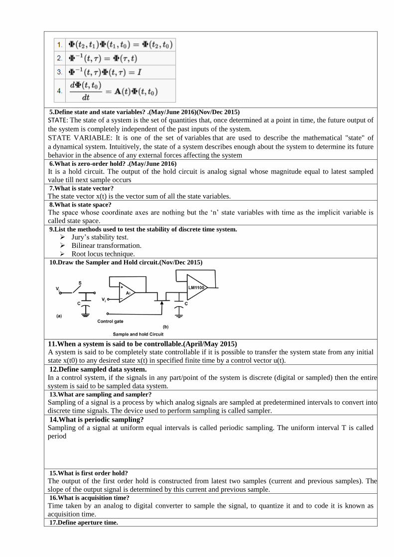
Root locus technique. 10.Draw the Sampler and Hold circuit.(Nov/Dec 2015)
11.When a system is said to be controllable.(April/May 2015)
A system is said to be completely state controllable if it is possible to transfer the system state from any initial
state x(t0) to any desired state x(t) in specified finite time by a control vector u(t).
12.Define sampled data system.
In a control system, if the signals in any part/point of the system is discrete (digital or sampled) then the entire
system is said to be sampled data system. 13.What are sampling and sampler?
Sampling of a signal is a process by which analog signals are sampled at predetermined intervals to convert into
discrete time signals. The device used to perform sampling is called sampler.
14.What is periodic sampling?
Sampling of a signal at uniform equal intervals is called periodic sampling. The uniform interval T is called
period
15.What is first order hold?
The output of the first order hold is constructed from latest two samples (current and previous samples). The
slope of the output signal is determined by this current and previous sample. 16.What is acquisition time?
Time taken by an analog to digital converter to sample the signal, to quantize it and to code it is known as
acquisition time. 17.Define aperture time.

It is the duration of sampling of analog signal. 18.What is settling time?
Time taken by a digital to analog converter to convert the given digital signal into analog signal magnitude and
be remain within the tolerance is called settling time. 19.When a system is referred as sampled data control system.
The overall system is hybrid in which the signal is in sampled form in the digital controller and in continuous
form in the rest of the system. A system of this kind is referred to as a sampled-data control system.
20.When a ZOH is used. .(May/June 2016)
Zero-order hold is used in conjunction with a high sampling rate to provide satisfactory performance.
21.What is state variable?
The state of a dynamical system is a minimal set of variables known as state variable such that the knowledge of these variables at t = t0 together with the knowledge of the inputs for t > =t0, completely determines the behavior of the system for t > t0
22.When a system is said to be observable.
A system is said to be completely state observable, if every state x(t0) can be completely identified by measurements of the outputs y(t) over a finite time interval. 23.
Give the state equation for observability.
24.What is state transition matrix?
The transition in state is carried out by the matrix exponential. Because of this property, is known as state
transition matrix and is denoted by (t). 25.Mention the need for state variables.(Nov/Dec 2010)
A state variable is one of the set of variables that are used to describe the mathematical "state" of a dynamical
system. Intuitively, the state of a system describes enough about the system to determine its future behavior in
the absence of any external forces affecting the system.
26.What is meant by quantization?(May/June 2011)(May/June 2012)
Quantization, in mathematics and digital signal processing, is the process of mapping a large set of input values
to a (countable) smaller set. Rounding and truncation are typical examples of quantization processes.
Quantization is involved to some degree in nearly all digital signal processing, as the process of representing a
signal in digital form ordinarily involves rounding.
27.What is meant by sampled data controlled system?(Nov/Dec 2012)
A sampled-data system is a control system in which a continuous-time plant is controlled with a digital device.
Under periodic sampling, the sampled-data system is time-varying but also periodic; thus, it may be modeled
by a simplified discrete-time system obtained by discretizing the plant
28.What are the advantages of state space representation?(May/June 2013)
It can be applied to non linear system.
It can be applied to tile invariant systems.
It can be applied to multiple input multiple output systems.
Its gives idea about the internal state of the system. 29.Define state equation?(Nov/Dec 2013)
It is defined as an equation that is used for determining state of a system.
30.Give the concept of controllability.(Nov/Dec 2013)(April/May 2015)
Controllability is an important property of a control system and the controllability property plays a crucial role
in many control problems. Controllability denotes the ability to move a system around in its entire
configuration space using only certain admissible manipulations.
State controllability condition implies that it is possible by admissible inputs to steer the states from any initial
value to any final value within some finite time window. A continuous time-invariant linear state-space model
is controllable if and only if
Where rank is the number of linearly independent rows in a matrix.
31.What are sampler and hold circuits?(Nov/Dec 2014)
A sample and hold circuit is an analog device that samples the voltage of a continuously varying analog
signal and holds its value at a constant level for a specified minimum period of time.
PART – B & C
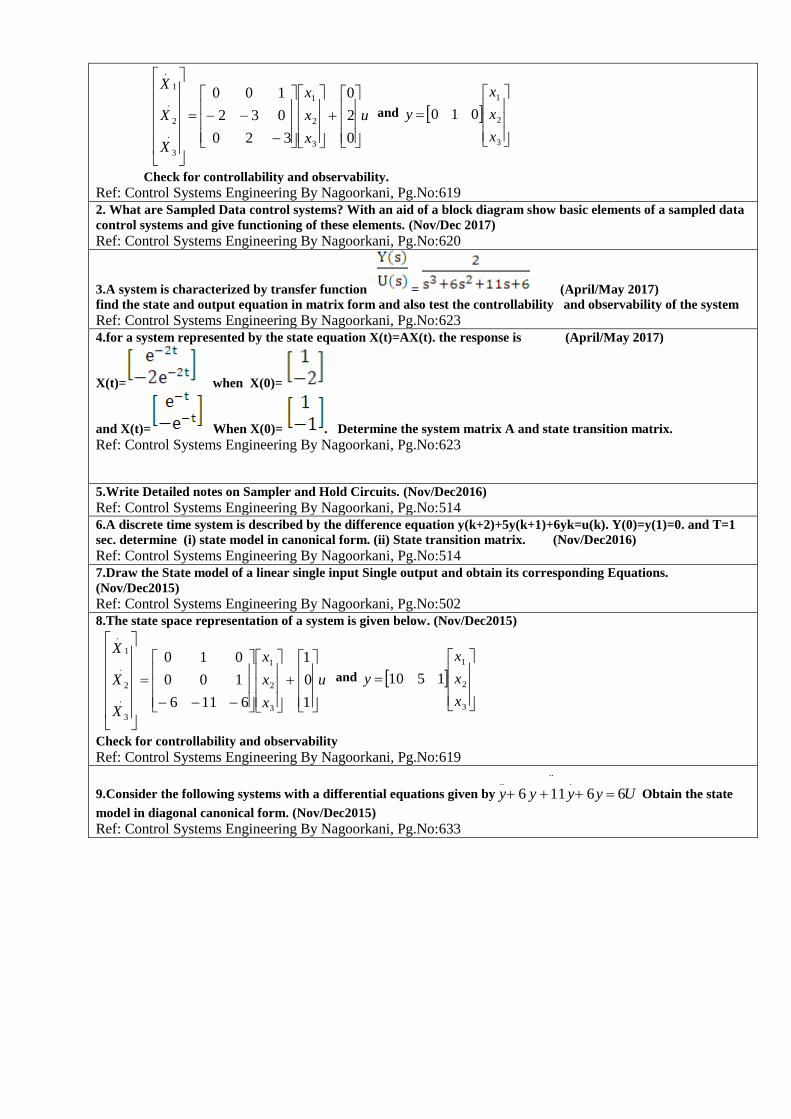
1.The state space representation of a system is given below. (Nov/Dec 2017)(Nov/Dec2016)
u
x
x
x
X
X
X
0
2
0
320
032
100
3
2
1
.
3
.
2
1
.
and
3
2
1
010
x
x
x
y
Check for controllability and observability.
Ref: Control Systems Engineering By Nagoorkani, Pg.No:619 2. What are Sampled Data control systems? With an aid of a block diagram show basic elements of a sampled data
control systems and give functioning of these elements. (Nov/Dec 2017)
Ref: Control Systems Engineering By Nagoorkani, Pg.No:620
3.A system is characterized by transfer function = (April/May 2017)
find the state and output equation in matrix form and also test the controllability and observability of the system Ref: Control Systems Engineering By Nagoorkani, Pg.No:623 4.for a system represented by the state equation X(t)=AX(t). the response is (April/May 2017)
X(t)= when X(0)=
and X(t)= When X(0)= . Determine the system matrix A and state transition matrix.
Ref: Control Systems Engineering By Nagoorkani, Pg.No:623
5.Write Detailed notes on Sampler and Hold Circuits. (Nov/Dec2016)
Ref: Control Systems Engineering By Nagoorkani, Pg.No:514 6.A discrete time system is described by the difference equation y(k+2)+5y(k+1)+6yk=u(k). Y(0)=y(1)=0. and T=1
sec. determine (i) state model in canonical form. (ii) State transition matrix. (Nov/Dec2016)
Ref: Control Systems Engineering By Nagoorkani, Pg.No:514 7.Draw the State model of a linear single input Single output and obtain its corresponding Equations.
(Nov/Dec2015)
Ref: Control Systems Engineering By Nagoorkani, Pg.No:502 8.The state space representation of a system is given below. (Nov/Dec2015)
u
x
x
x
X
X
X
1
0
1
6116
100
010
3
2
1
.
3
.
2
1
.
and
3
2
1
1510
x
x
x
y
Check for controllability and observability
Ref: Control Systems Engineering By Nagoorkani, Pg.No:619
9.Consider the following systems with a differential equations given by Uyyyy 66116
.....
Obtain the state
model in diagonal canonical form. (Nov/Dec2015)
Ref: Control Systems Engineering By Nagoorkani, Pg.No:633

COURSE DELIVERY PLAN-THEORY
Faculty Name : Dr.J.Jebastine
Mrs.R.Gracelin Sheeba Programme/Branch: B.E /ECE
Academic Year:2017-2018 Year/Semester/Batch: II/IV/2016-2020
Subject Code/Subject Name: EC6405/Control System Engineering
Regulation: R2013
A. Details of the relevant POs & PSOs supported by the course
PO1 Engineering Knowledge: Apply the knowledge of mathematics, science, engineering fundamentals, and
electronics engineering specialization to the solution of complex engineering problems.
PO2
Problem analysis: Identify, formulate, review research literature, and analyze complex engineering
problems reaching substantiated conclusions using first principles of mathematics, natural sciences, and
engineering sciences.
PO3
Design/development of solutions: Design solutions for complex engineering problems and design system
components or processes that meet the specified needs with appropriate consideration for the public health
and safety, and the cultural, societal, and environmental considerations.
PO4
Conduct investigations of complex problems: Use research-based knowledge and research methods
including design of experiments, analysis and interpretation of data, and synthesis of the information to
provide valid conclusions.
PO5
Modern tool usage: Create, select, and apply appropriate techniques, resources, and modern engineering
and IT tools including prediction and modeling to complex engineering activities with an understanding of
the limitations.
PO6
The engineer and society: Apply reasoning informed by the contextual knowledge to assess societal,
health, safety, legal and cultural issues and the consequent responsibilities relevant to the professional
engineering practice.
PO9 Individual and team work: Function effectively as an individual, and as a member or leader in diverse
teams, and in multidisciplinary settings.
PO10
Communication: Communicate effectively on complex engineering activities with the engineering
community and with society at large, such as, being able to comprehend and write effective reports and
design documentation, make effective presentations, and give and receive clear instructions.
PO11
Project management and finance: Demonstrate knowledge and understanding of the engineering and
management principles and apply these to one‟s own work, as a member and leader in a team, to manage
projects and in multidisciplinary environments.
PO12
Life-long learning: Recognize the need for, and have the preparation and ability to engage in independent
and life-long learning in the broadest context of technological change.
PSO I Competence in using modern electronic tools in hardware and software co-design for networking and
communication applications.
PSO II Promote excellence in professional career and higher education by gaining knowledge in the field of
Electronics and Communication Engineering
PSO
III
Understand social needs and environmental concerns with ethical responsibility to become a successful
professional.
B. Details of COs Mapping with PO/PSOs identified for the course
Course
Outcome Course Description
Program Outcomes/Program Specific Outcome
PO
1
PO
2
PO
3
PO
4
PO
5
PO
6
PO
7
PO
8
PO
9
PO
10
PO
11
PO
12
PS
O1
PS
O2
PS
O3
C214.1 Implement various
reduction techniques in
control system modeling.
3 3 3 3 2 3 - - 1 1 2 1 3 2 2
C214.2 Analyze the time response,
frequency response and the
stability of systems.
3 2 2 2 3 2 - - - 1 1 1 3 1 1
C214.3 Examine the stability of
control systems using
different plots.
3 3 2 2 3 2 - - - 2 1 1 3 2 1

C214.4 Evaluate the dynamic
behavior of control systems
using state space model.
3 3 2 2 2 2 - - 2 2 1 2 3 2 1
C214.5 Express and solve system
equations in state-variable
form.
3 3 2 2 3 1 - - 2 2 1 2 2 2 1
C. Syllabus of the course UNIT I CONTROL SYSTEM MODELING 9
Basic Elements of Control System – Open loop and Closed loop systems - Differential equation - Transfer
function, Modeling of Electric systems, Translational and rotational mechanical systems - Block diagram
reduction Techniques - Signal flow graph
UNIT II TIME RESPONSE ANALYSIS 9 Time response analysis - First Order Systems - Impulse and Step Response analysis of second order systems -
Steady state errors – P, PI, PD and PID Compensation, Analysis using MATLAB UNIT III FREQUENCY RESPONSE ANALYSIS 9 Frequency Response - Bode Plot, Polar Plot, Nyquist Plot - Frequency Domain specifications from the plots -
Constant M and N Circles – Nichol‟s Chart - Use of Nichol‟s Chart in Control System Analysis. Series, Parallel,
series-parallel Compensators - Lead, Lag, and Lead Lag Compensators, Analysis using MATLAB UNIT IV STABILITY ANALYSIS 9 Stability, Routh-Hurwitz Criterion, Root Locus Technique, Construction of Root Locus, Stability, Dominant Poles, Application of Root Locus Diagram - Nyquist Stability Criterion - Relative Stability, Analysis using MATLAB UNIT V STATE VARIABLE ANALYSIS 9
State space representation of Continuous Time systems – State equations – Transfer function from State Variable
Representation – Solutions of the state equations - Concepts of Controllability and Observability – State space
representation for Discrete time systems. Sampled Data control systems – Sampling Theorem – Sampler & Hold –
Open loop & Closed loop sampled data systems.
D. Content Beyond Syllabus: 1. Dry EDM
2.Application of Cryogenic cooling in Machining
3.
F. Delivery Resources:
Text Book(s): T1: J.Nagrath and M.Gopal, “Control System Engineering”, New Age International Publishers, 5
th Edition, 2007.
Reference Book(s): R1:Benjamin.C.Kuo, “Automatic control systems”, Prentice Hall of India, 7
th Edition,1995.
R2:M.Gopal, “Control System – Principles and Design”, Tata McGraw Hill, 2nd
Edition, 2002. R3: Schaum‟s Outline Series, “Feed Back and Control Systems” Tata McGraw-Hill, 2007. R4:John J.D‟Azzo & Constantine H.Houpis, “Linear Control System Analysis and Design‟”, Tata Mc
Graw-Hill, Inc., 1995.
R5:Richard C. Dorf and Robert H. Bishop, “Modern Control Systems”, Addison – Wesley, 1999.
On line learning materials (and Others if any): 1. nptel.ac.in/courses/112105126/39
2.

UNIT I CONTROL SYSTEM MODELING
Topic to be Covered
Delivery Resources
Delivery
Method Text Book
with Pg.No
Reference
Book (if any
with Pg.No)
Online Resource
(Web Link of the
Specific Topic)
Basic Elements of Control System Open loop and Closed loop systems Differential equation Transfer function Modeling of Electric systems Translational and rotational mechanical
systems
Block diagram reduction Techniques Signal flow graph
Course Outcome: C214.1: Implement various reduction techniques in control system modeling. No of hours in the syllabus :12
No of hours planned :12
No of hours taught :12
UNIT II TIME RESPONSE ANALYSIS
Topic to be Covered
Delivery Resources
Delivery
Method Text Book
with Pg.No
Reference
Book (if any
with Pg.No)
Online Resource
(Web Link of the
Specific Topic)
Time response analysis First Order Systems Impulse and Step Response analysis of second
order systems
Steady state errors P, PI, PD and PID Compensation Analysis using MATLAB
Course Outcome: C214.2: Analyze the time response, frequency response and the stability of systems.. No of hours in the syllabus :12
No of hours planned :12
No of hours taught :12
UNIT III FREQUENCY RESPONSE ANALYSIS
Topic to be Covered
Delivery Resources
Delivery
Method Text Book
with Pg.No
Reference
Book (if any
with Pg.No)
Online Resource
(Web Link of the
Specific Topic)
Frequency Response -, , - –Analysis. Series,
Parallel, series-parallel Compensators - Lead,
Lag, and Lead Lag Compensators, Analysis
using MATLAB
Time response analysis
Bode Plot Polar Plot Nyquist Plot Frequency Domain specifications from the
plots - Constant M and N Circles
Nichol‟s Chart - Use of Nichol‟s Chart in
Control System Analysis

Course Outcome: C214.2: Analyze the time response, frequency response and the stability of systems.. No of hours in the syllabus :12
No of hours planned :12
No of hours taught :12