jet neutron, gamma & particle diagnostics · 2013-05-30 · jet neutron, gamma & particle...
TRANSCRIPT
D. B. Syme et al, EIROForum May 2013
JET Neutron, Gamma & Particle JET Neutron, Gamma & Particle
DiagnosticsDiagnostics
Brian SymeBrian Syme
EIROForumEIROForum 2013, May 20132013, May 2013
D. B. Syme et al, EIROForum May 2013
AcknowledgementsAcknowledgements
JET Neutron, Gamma & Particle DiagnosticsJET Neutron, Gamma & Particle Diagnostics
D.B. Syme1, S. Popovichev1, V. Kiptily1, L. Giacomelli2, S. Conroy3, P. Beaumont1,
M. Santala4, G. Ericsson3, M. Weiszflog3, A. Hjalmarsson3, C. Hellesen3,
H. Henriksson3, G. Gorini2, M. Tardocchi2, R. Pereira5, A Fernandez5, M. Riva6, F. Belli6
and JET EFDA contributors*
[email protected], [email protected], Culham Science Centre, Abingdon, OX14 3DB, UK
1EURATOM-CCFE Fusion Association, Culham Science Centre, Abingdon, OX14 3DB, UK2 EURATOM-CNR Fusion Association, Istituto di Fisica del Plasma "Piero Caldirola“, CNR, Milano, Italy
3 EURATOM-VR Fusion Association , Department of Physics and Astronomy, Uppsala, Sweden4 EURATOM-Tekes Fusion Association, VTT Technical Research Centre, P.O. Box 1000, FI-02044 VTT, Finland
5 EURATOM-IST Fusion Association, Instituto de Plasmas e Fusão Nuclear / IST
Av. Rovisco Pais, 1049-001 Lisboa Portugal6 Associazione EURATOM-ENEA sulla Fusione, C.P. 65, Frascati I-00044, Roma (Italy)
* See the Appendix of F. Romanelli et al, Proceedings of the 24th IAEA Fusion Energy
Conference 2012, San Diego, USA.

D. B. Syme et al, EIROForum May 20133
Fusion energy researchFusion energy research
-- Ions, neutrons and fusion productsIons, neutrons and fusion products
Fusion powerFusion power has the potential to provide energy in the futurehas the potential to provide energy in the future
in a sustainable way in a sustainable way –– reactions between hydrogen ionsreactions between hydrogen ions
–– 22D + D + 22D D ��33He (0.82 He (0.82 MeVMeV) + ) + n n ((2.452.45 MeVMeV)) 50%50%
–– �� 33T (1.11 T (1.11 MeVMeV) + p (3.02 ) + p (3.02 MeVMeV) 50%) 50%
–– 22D + D + 33T T ��44He (3.5 He (3.5 MeVMeV) + ) + nn ((14.114.1 MeVMeV))–– 22D + D + 33HeHe ��44He (3.6 He (3.6 MeVMeV) + p (14.7 ) + p (14.7 MeVMeV))
–– 33T + T + 33T T ��4He + 4He + 2n2n <11.3 <11.3 MeVMeV>>
DD--T is favouredT is favoured: : -- Best yield at lowest temperature (ion energy)Best yield at lowest temperature (ion energy)
Need Need containmentcontainment at high temperature and densityat high temperature and density
In the SunIn the Sun –– Gravitational containmentGravitational containment
On Earth On Earth –– Magnetic containment Magnetic containment
–– ‘‘TokamaksTokamaks’ like JET are now favoured’ like JET are now favoured
–– Maximise Fusion Product = Maximise Fusion Product = ni.Tini.Ti..ττee
Arising points for DiagnosticsArising points for Diagnostics–– Neutrons measure the fusion yield Neutrons measure the fusion yield –– directlydirectly
–– Same number of p, Same number of p, 33T ions as T ions as nn in a D,D plasma in a D,D plasma
–– There are There are 33TT ions + 14 ions + 14 MeVMeV neutrons, even in D,D plasmasneutrons, even in D,D plasmas
From Triton From Triton ‘‘burnupburnup’’
And tritium adsorbed in the wallsAnd tritium adsorbed in the walls
. 1.E-04
1.E-03
1.E-02
1.E-01
1.E+00
1.E+01
1 10 100 1000
kT (keV)
cro
ss s
ectio
n (
ba
rn)
D-D D-TD-3HeT-T
10
1
10 -1
10 -2
10 -3
10 -4
MASTMAST

D. B. Syme et al, EIROForum May 2013
The present world leading machine is The present world leading machine is
JETJET ((JJoint oint EEuropean uropean TTorusorus), A European project, operated ), A European project, operated by by EuratomEuratom
16 MW peak D16 MW peak D--T fusion power and closest approach to T fusion power and closest approach to breakbreak--even (Q~1) [1997]even (Q~1) [1997]
Flexible machine with 25 years operation, Flexible machine with 25 years operation,
JET machine parameters and & plasma conditions are JET machine parameters and & plasma conditions are nearest to those of the next step = ITERnearest to those of the next step = ITER (now in build)(now in build)
<NBI, ICRH & LH heating types, Be, Tritium facilities ><NBI, ICRH & LH heating types, Be, Tritium facilities >
Fusion energy researchFusion energy research
-5
-4
-3
-2
-1
0
1
2
3
4
5
0 2 4 6 8 10
radial distance from toroidal axis (m)
vertical distance from m
idplane (m
)
T-3MASTJETITER
D. B. Syme et al, EIROForum May 2013
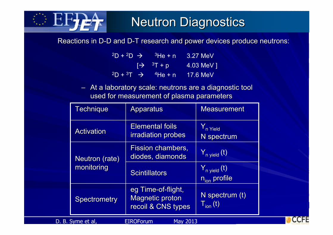
–– At a laboratory scale: neutrons are a diagnostic tool At a laboratory scale: neutrons are a diagnostic tool
used for used for measurement of plasma parametersmeasurement of plasma parameters
Neutron DiagnosticsNeutron Diagnostics
Reactions in DReactions in D--D and DD and D--T research and power devices produce neutrons:T research and power devices produce neutrons:
2D + 2D � 3He + n 3.27 MeV
[� 3T + p 4.03 MeV ]
2D + 3T � 4He + n 17.6 MeV
YYnn yield yield (t)Fission chambers, Fission chambers,
diodes, diamondsdiodes, diamonds
YYnn YieldYield
N spectrumN spectrum
Elemental foils Elemental foils
irradiation probesirradiation probesActivationActivation
YYnn yield yield (t)
nnionion profileprofileScintillatorsScintillators
Neutron (rate) Neutron (rate)
monitoringmonitoring
N spectrum (t)N spectrum (t)
TTionion (t)(t)
egeg TimeTime--ofof--flight,flight,
Magnetic proton Magnetic proton
recoil & CNS typesrecoil & CNS typesSpectrometrySpectrometry
MeasurementMeasurementApparatusApparatusTechniqueTechnique

D. B. Syme et al, EIROForum May 20136
Neutron Diagnostics measurements:
• Time resolved neutron yield• Time integrated absolute neutron yield• Radial profile of the neutron emission• Neutron energy spectra.
+ recently a range of Fast Ion Diagnostics• Fast ion loss detectors (FILD)• Fusion gamma diagnostics• Alfven Eigenmodes Antennas • Neutral Particle Analyserseutral Particle Analysers
Measurement ChallengesMeasurement Challenges•• 10 s pulses/20 10 s pulses/20 minsmins, N, N--yield range: 10yield range: 108 -- 10102020
•• Extended N source (Extended N source (ToroidalToroidal, R~3m, H~1, R~3m, H~1--2m)2m)
•• Magnetic Fields, EM interference, Mechanical Magnetic Fields, EM interference, Mechanical
Vibrations Vibrations
•• High N, X & GammaHigh N, X & Gamma--ray backgroundsray backgrounds
•• Radiation Damage levels, Restricted accessRadiation Damage levels, Restricted access
•• [D,T equipment to be remotely handled][D,T equipment to be remotely handled]
Complementary TechniquesComplementary Techniques are always required are always required
[Different views, shielding, responses, sensitivities, +/[Different views, shielding, responses, sensitivities, +/––’’s]s]
JET Neutron Diagnostics JET Neutron Diagnostics -- Measurements & ChallengesMeasurements & Challenges
From its beginning (1983), JET has had an extensive set of Neutron Diagnostics
Fields of View

D. B. Syme et al, EIROForum May 20137
TimeTime--resolved Total Neutron Yield Monitor resolved Total Neutron Yield Monitor
(2.45 (2.45 MeVMeV plus 14 plus 14 MeVMeV both included)both included)
3 pairs of fission chambers - U235 & U238
� Located around JET (on the limbs in Oct. 2, 8 and 6).� Wide Range of neutron yields: 1010 to 1020 n/s� Electronics: (All analogue)
HV, preamps, log amps, high linearity� Absolutely calibrated to <10%, periodic verification
JET Time-Resolved Neutron Yield Monitors
• Threshold (n,p) and (n,a) reactions in SiSi diodesdiodes & Diamonds• Range: 1013 - 1018 n/s
Time-resolved 14 MeVNeutron Yield Monitor
D. B. Syme et al, EIROForum May 2013
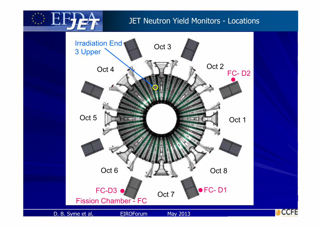
JET Neutron Yield Monitors - Locations
Oct 8Oct 6
Oct 3
Oct 2
Oct 8
FC- D1FC-D3
FC- D2
Oct 1
Irradiation End 3 Upper
Fission Chamber - FCOct 7
Oct 5
Oct 4
Oct 6 Oct 8Oct 6
Oct 3
Oct 2
Oct 8
FC- D1FC-D3
FC- D2
Oct 1
Irradiation End 3 Upper
Fission Chamber - FCOct 7
Oct 5
Oct 4
Oct 6

D. B. Syme et al, EIROForum May 2013
•• 88 Irradiation ends located in 5 octants :
• Capsules containing sample foils are delivered and retrieved pneumatically
•• CConventional gamma-radiation measurementsRange: 1014 to >1020 n/s
most widely used reactions at JET:DD - 115In(n,n’)115mIn, DT - 28Si (n,p)28AL, 63Cu(n,2n)62Cu, 56Fe(n,p)56Mndetectors : 3 NaI, HpGe (absolutely calibrated)
•• CCounting of delayed neutrons - Range 1014 to >1020 n/s
After N,fission reactions in (235U,238U,232Th) foilsGives DD neutron yield, when Y(DD)>> Y(DT)detector system: 2 stations with six 3He counters
• Accuracy typically ~ 8-10%for both DD and DT neutron yields delayed neutron measurements can give 7%
JET Neutron Yield Monitors - Activation
JET Activation System
(Octant 3 Upper) Irradiation End – I.E
JET Mechanical Support Structure
Vaccum Vessel (Double-walled)
Iter-Like Wall (Plasma-facing)
JET Octant 3 Cross-section
D. B. Syme et al, EIROForum May 201310
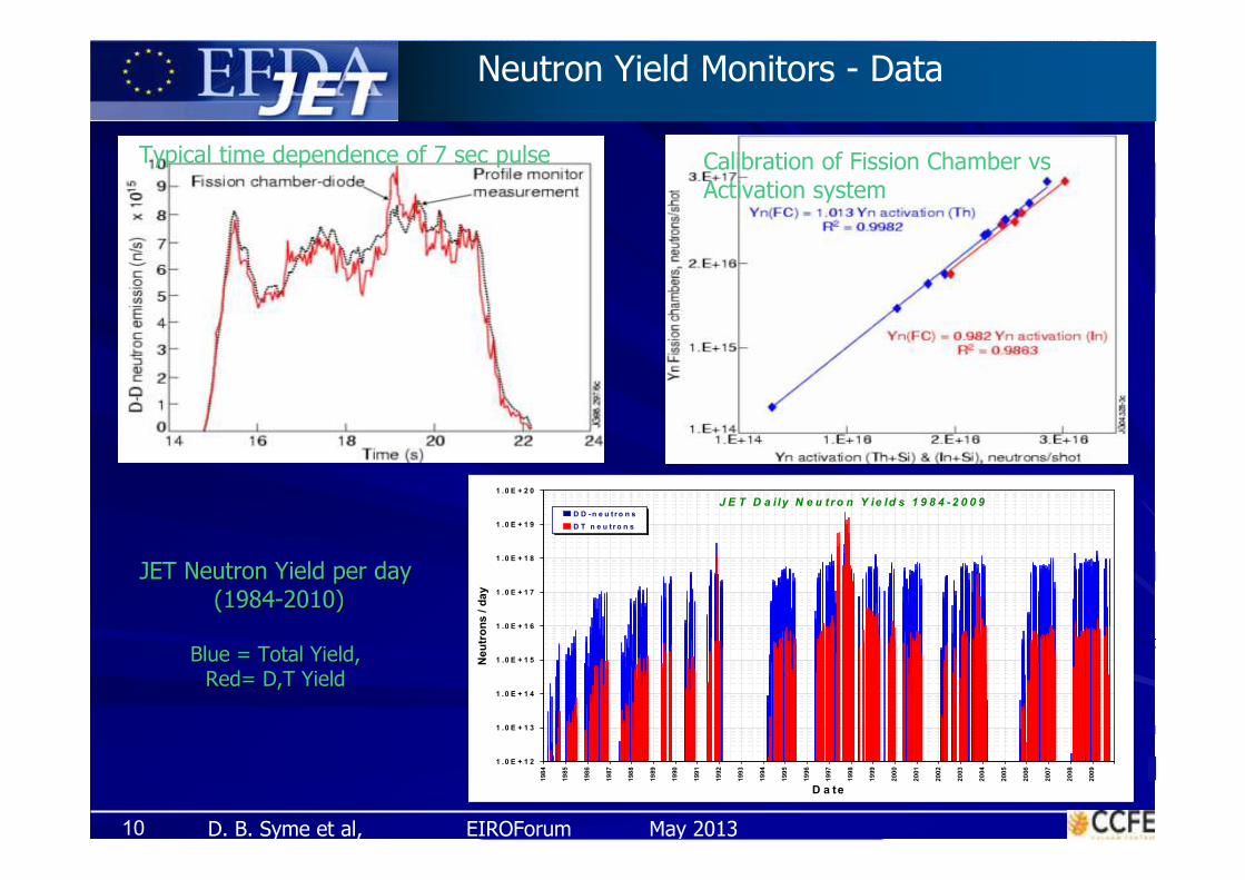
Calibration of Fission Chamber vsActivation system
Typical time dependence of 7 sec pulse
JET Neutron Yield per dayJET Neutron Yield per day
(1984(1984--2010)2010)
Blue = Total Yield,Blue = Total Yield,
Red= D,T YieldRed= D,T Yield
Neutron Yield Monitors - Data
J E T D a i ly N e u t ro n Y ie ld s 1 9 8 4 -2 0 0 9
1 .0 E + 1 2
1 .0 E + 1 3
1 .0 E + 1 4
1 .0 E + 1 5
1 .0 E + 1 6
1 .0 E + 1 7
1 .0 E + 1 8
1 .0 E + 1 9
1 .0 E + 2 0
198
4
19
85
198
6
19
87
198
8
19
89
19
90
199
1
19
92
199
3
19
94
199
5
19
96
19
97
199
8
19
99
200
0
20
01
200
2
20
03
20
04
200
5
20
06
200
7
20
08
200
9
D a te
Neu
tro
ns
/ d
ay
D D -n e u t r o n s
D T n e u t r o n s

D. B. Syme et al, EIROForum May 201311
JET Neutron Yield JET Neutron Yield -- CalibrationCalibration
Need absolute measure of fusion rateNeed absolute measure of fusion rate
Need Absolute Calibration of Neutron EmissionNeed Absolute Calibration of Neutron Emission
versus a calibrated neutron source in the versus a calibrated neutron source in the torustorus, , egeg 252252--CfCf
Last done in 1985Last done in 1985--9, for the Fission Chambers only, 9, for the Fission Chambers only,
<All<All--metal JET. No metal JET. No DivertorDivertor, Plasma Centre was lower by 30 cm.>, Plasma Centre was lower by 30 cm.>
Calibration extended by a succession of calculations, since thenCalibration extended by a succession of calculations, since then
How it has been set up in 1985/9
1985/9 Method:
Pull a strong calibrated
neutron source round
the torus in a tube.
Observe response from
external Fission
Chambers per source
neutron => calibration

D. B. Syme et al, EIROForum May 2013
March 2010 - During ShutdownJET 1985
The JET Experiment The JET Experiment -- Changing since 1983Changing since 1983
JET 1991
Inside JET 1985 2011 JET ITER-Like WallInside JET 1994

D. B. Syme et al, EIROForum May 201313
Auxiliary Shield
In ISO container
Oct5 Boom Tent
Transport Flask
In Loading BayTCTF Tent Operational Shield
Mascot
11 m Port to Port
Contingency Provisions Normal Operations
Source loading & deploymentSafe source storage
R-H Deployment Environment

D. B. Syme et al, EIROForum May 201314
JET JET NNeutroneutron SSourceource Calibration Calibration -- 20132013
a) 40 steps round vessel in plasma centre locations
b) 1 set of radial & vertical scans at a port
c) Scan under Irradiation End – First direct calibration
d) Basket scan: 40 steps x 5 rings round vessel - with +/- 50 cm in Z, R
e) Direct Comparison of Activation and Fission Chamber methods for 252Cf
Improves old JET calibration
Precursor to JET D,T Calibrations
Addresses many questions relevant to ITER Calibrations
eg Corrections for –
Non symmetric sources
Scattering effects, eg source holder & support structure
Point vs 3D calibrations
Torus practicalities
Direct calibration of JET neutron monitors, versus a standard 252Cf source in-torus
Deployment plan on right

D. B. Syme et al, EIROForum May 2013
Progressive reduction of Raw FC neutrons observed per JET neutroProgressive reduction of Raw FC neutrons observed per JET neutronn
as JET ports regions became congested and Limiters were addedas JET ports regions became congested and Limiters were added
Note: No information from this on the effect of recent torus inner wall changes,
as there was no neutron calibration in the earlier ‘carbon wall’ period
Reduction in FC rate
per JET neutron
X 2 in 29 years
FC Oct 6: Raw Counts: Historical Comparison to 1984 data
(for the same Cf Neutron Rate)
Note: this is not a
calibration coefficient

D. B. Syme et al, EIROForum May 201316
M. Adams et al., NIM, A 329 (1993)
Two cameras:Two cameras:
Vertical: 9 linesVertical: 9 lines--ofof--sightsight
Horizontal: 10 linesHorizontal: 10 lines--ofof--sightsight
FanFan--shaped array of shaped array of remotely adjustable remotely adjustable collimators collimators with two apertures.with two apertures.
Space resolution: Space resolution: ~8 ~8 (or ~15)cm(or ~15)cm (in the centre(in the centre
Detectors:Detectors:
-- NE213 liquid NE213 liquid scintillatorsscintillators (2.5 and 14 (2.5 and 14 MeVMeV)) + PSD; + PSD;
-- Plastic Bicron418 Plastic Bicron418 scintillatorsscintillators (14 (14 MeVMeV))
--CsI(TlCsI(Tl) photodiodes) photodiodes (Hard X rays and g emission (Hard X rays and g emission 0.2<0.2<EgEg<6 <6 MeVMeV).).
DAQ: Recently converted from analog to digital
Plasma coverage allows 2D pseudo Plasma coverage allows 2D pseudo -- tomographytomography
CoversCovers both DD and DT regimes of operationboth DD and DT regimes of operation
JET Neutron Profile Monitor & Gamma Camera
Neutron detectors are absolutely calibratedNeutron detectors are absolutely calibrated
D. B. Syme et al, EIROForum May 201317
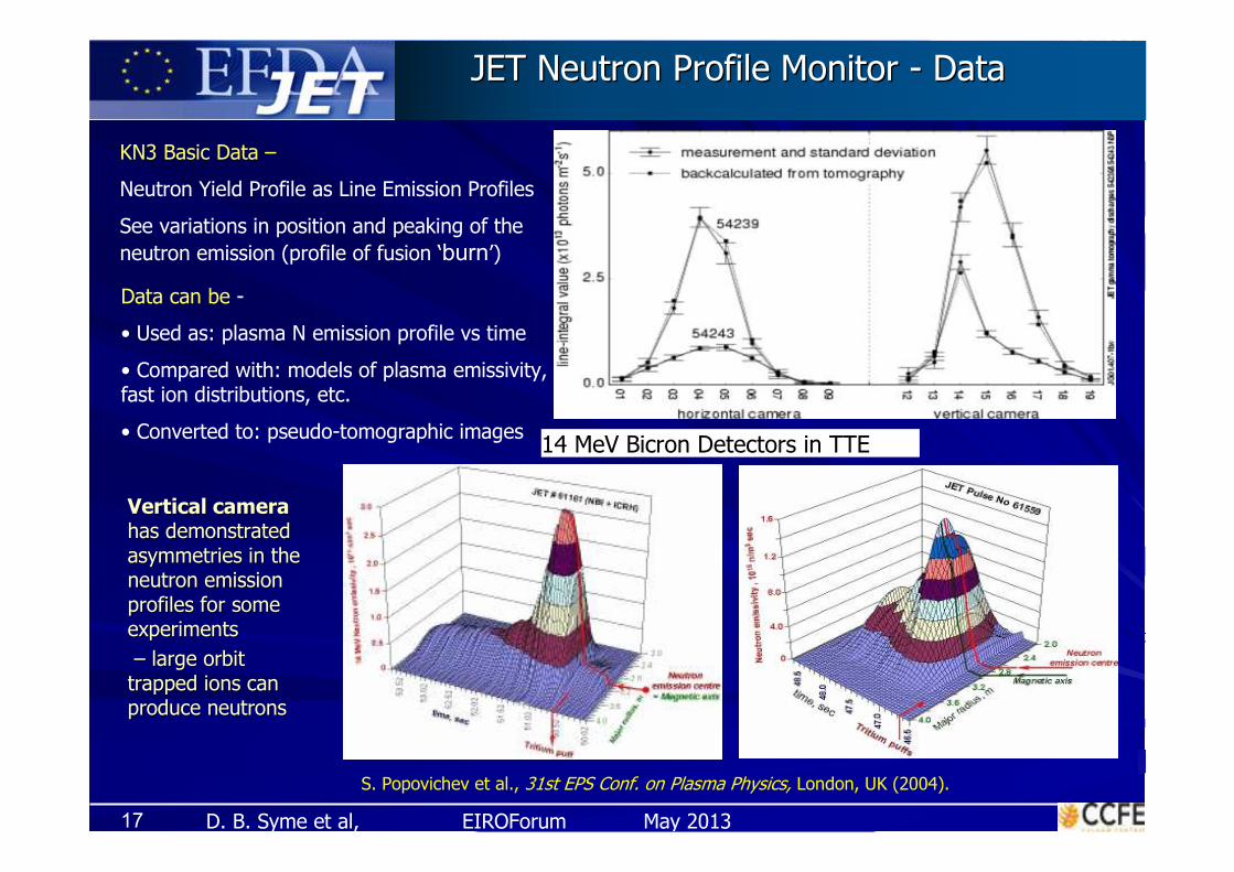
KN3 Basic Data –
Neutron Yield Profile as Line Emission Profiles
See variations in position and peaking of the
neutron emission (profile of fusion ‘burn’)
JET Neutron Profile Monitor JET Neutron Profile Monitor -- DataData
Data can be -
• Used as: plasma N emission profile vs time
• Compared with: models of plasma emissivity, fast ion distributions, etc.
• Converted to: pseudo-tomographic images14 MeV Bicron Detectors in TTE
S. Popovichev et al., 31st EPS Conf. on Plasma Physics, London, UK (2004).
Vertical cameraVertical camera
has demonstrated has demonstrated
asymmetries in the asymmetries in the
neutron emission neutron emission
profiles for some profiles for some
experimentsexperiments
–– large orbit large orbit
trapped ions can trapped ions can
produce neutronsproduce neutrons
D. B. Syme et al, EIROForum May 201318
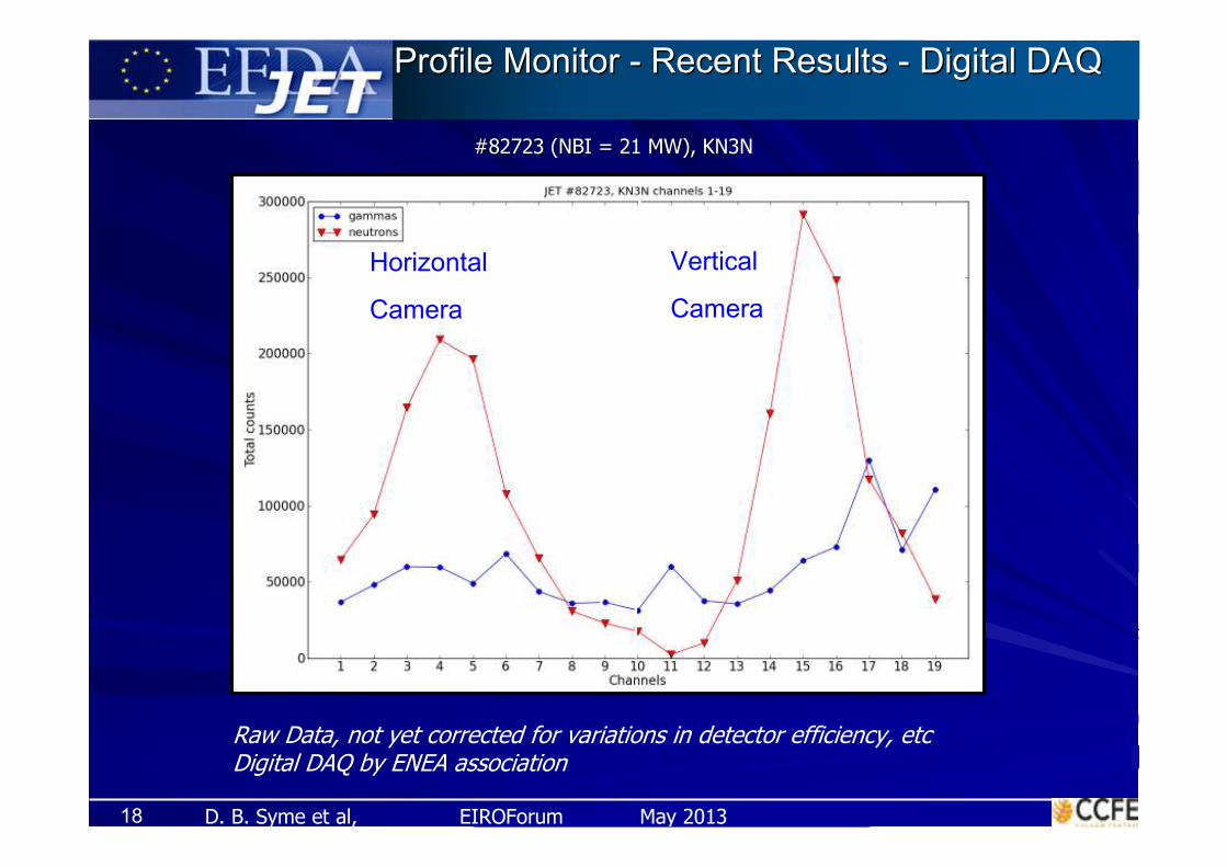
Profile Monitor Profile Monitor -- Recent Results Recent Results -- Digital DAQDigital DAQ
#82723 (NBI = 21 MW), KN3N#82723 (NBI = 21 MW), KN3N
Raw Data, not yet corrected for variations in detector efficiency, etcDigital DAQ by ENEA association
Vertical
Camera
Horizontal
Camera

D. B. Syme et al, EIROForum May 2013
Spectrometry Principles for Neutrons
Measurement of neutron energy - by transfer of momentum/energy from neutron to recoil proton
a) Measurement of recoil proton momentum in dispersive magnetic spectrometer (MPR)
b) Timing of recoil neutron (TOF) from scattering detector to 2nd
detector (TOFOR)
b’) Direct measurement of recoil proton energy from thin foil - in SSD detector (not shown)
c) Proton absorption by scintillator -proportional conversion to light, then to an electronic signal, amplification & DAQ processes -‘compact neutron spectrometer’ Fig. Giacommeli et al, Nucl. Fusion 45 (2005)
D. B. Syme et al, EIROForum May 2013
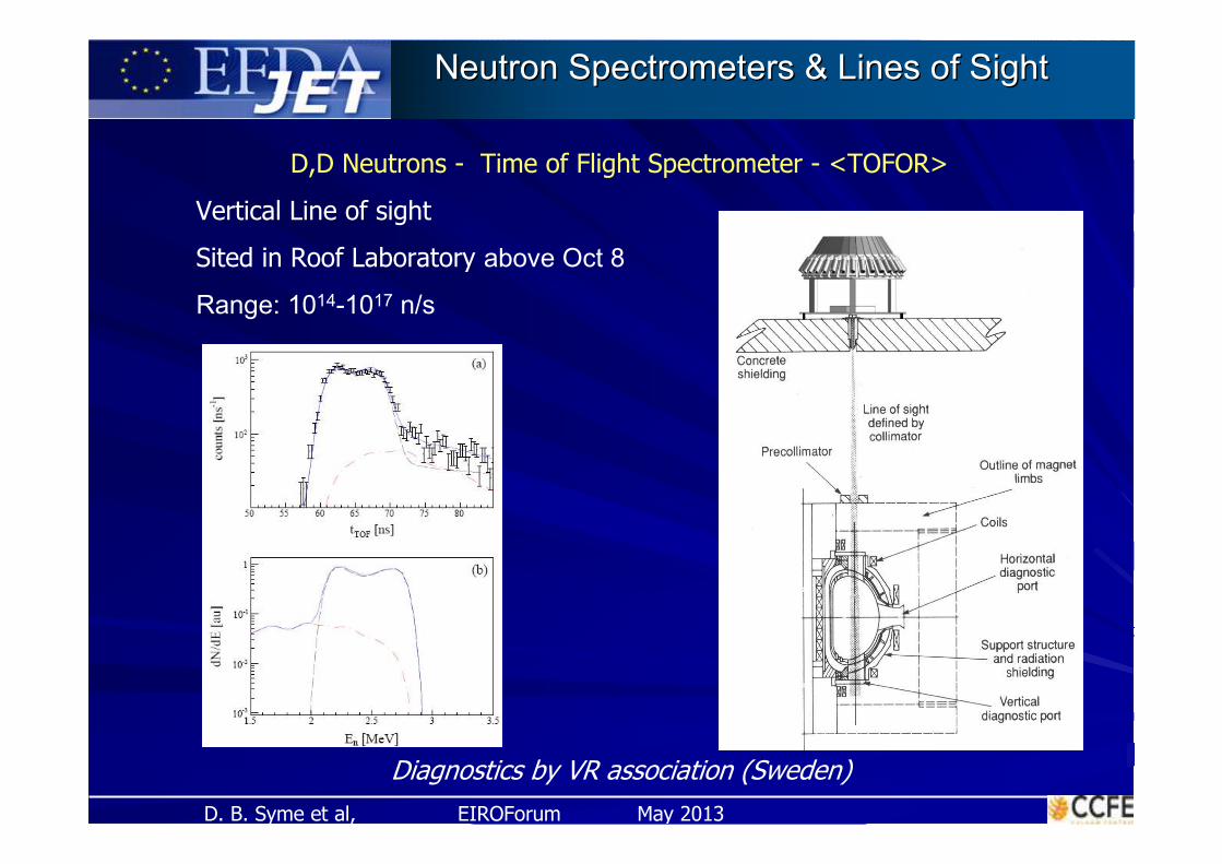
D,D Neutrons - Time of Flight Spectrometer - <TOFOR>
Vertical Line of sight
Sited in Roof Laboratory above Oct 8
Range: 1014-1017 n/s
Neutron Spectrometers & Lines of SightNeutron Spectrometers & Lines of Sight
Diagnostics by VR association (Sweden)

D. B. Syme et al, EIROForum May 2013
Neutron Spectrometers & Lines of SightNeutron Spectrometers & Lines of Sight
D,T (D,D) neutrons - Magnetic Proton Recoil spectrometer <MPRu>
Plasma self-heated thermal peak (top)
- Peak width – ion temperature
ICRF-Heated D,T Plasma (bottom)
- Broadened Thermal peak - Ion Temperature
- and High Energy Neutrons
Horizontal - Tangential LoS,
Looking from Oct 4 to Oct 7
Sited in a Separate Shield in the Torus Hall
Diagnostics by VR association (Sweden)

D. B. Syme et al, EIROForum May 2013
Neutron Spectrometers & Lines of SightNeutron Spectrometers & Lines of Sight
Compact Neutron Spectrometer - <CNS>
For D,D & D,T Neutrons
Horizontal - Tangential LoS,
Looking from Oct 7 to Oct 2
Sited in Bunker Outside Torus Hall
CNS
Range: 1014-1017 n/s

D. B. Syme et al, EIROForum May 2013
NE213 CNS Spectrometer Data and Digital DAQ
Ne213 Spectrometer (left) and StilbeneScintillators, sharing an annular neutron field in a JET bunker
The NE213 response function was measured at PTB, in an ENEA project
NE213 scintillator detector (BC501A) with a 207Bi γ source for long term stability monitoring & LED for short-time PM gain corrections.Digital DAQ for PSD, Pulse Height analysis, and event time stamping
Pulse-height
Spectrum
PSD
data
D. B. Syme et al, EIROForum May 2013
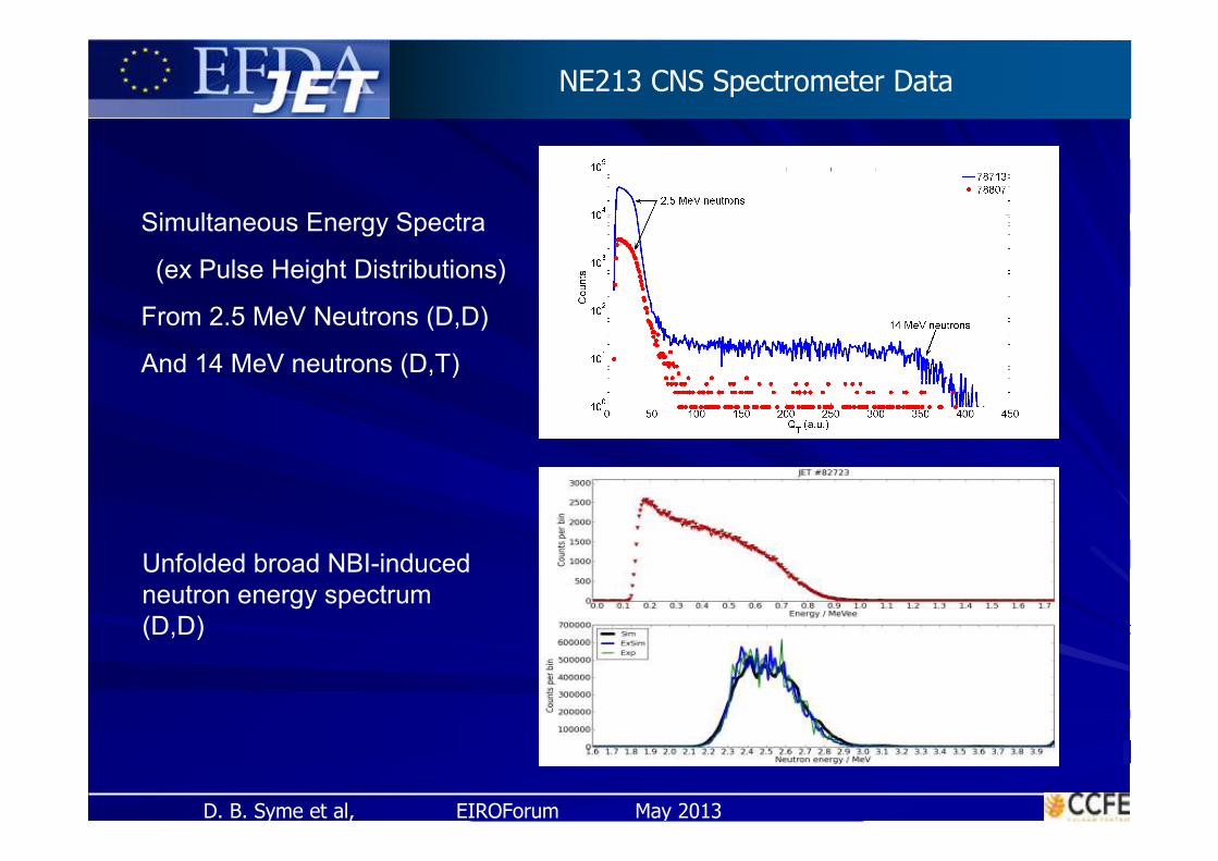
Unfolded broad NBI-induced
neutron energy spectrum
(D,D)
Simultaneous Energy Spectra
(ex Pulse Height Distributions)
From 2.5 MeV Neutrons (D,D)
And 14 MeV neutrons (D,T)
NE213 CNS Spectrometer Data
D. B. Syme et al, EIROForum May 201325
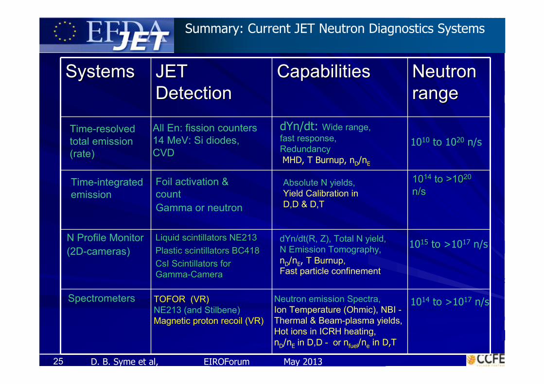
SystemsSystems JET JET
DetectionDetectionCapabilitiesCapabilities Neutron Neutron
range range
10101414 to >10to >102020
n/sn/s
Liquid Liquid scintillatorsscintillators NE213 NE213
Plastic Plastic scintillatorsscintillators BC418BC418
CsICsI ScintillatorsScintillators for for
GammaGamma--CameraCamera
Time-resolved
total emission
(rate)
Time-integrated
emission
N Profile Monitor
(2D-cameras)
Spectrometers
All En: fission counters
14 MeV: Si diodes,
CVD
dYn/dt: Wide range,
fast response,
Redundancy
MHD, T Burnup, nD/nE
Foil activation &
count
Gamma or neutron
Absolute N yields,
Yield Calibration in
D,D & D,T
TOFOR (VR)
NE213 (and Stilbene)
Magnetic proton recoil (VR)
Neutron emission Spectra,
Ion Temperature (Ohmic), NBI -
Thermal & Beam-plasma yields,
Hot ions in ICRH heating,
nD/nE in D,D - or nnfuelfuel/n/nee in D,Tin D,T
dYn/dt(R, Z), Total N yield,
N Emission Tomography,
nD/nE, T Burnup,Fast particle confinement
1010 to 1020 n/s
1014 to >1017 n/s
1015 to >1017 n/s
Summary: Current JET Neutron Diagnostics Systems

D. B. Syme et al, EIROForum May 201326
Fast ions occur in the plasma from -
fusion products: p (3 & 15 MeV), T (1 MeV), 3He(0.8 MeV), αα ((3.5 MeV3.5 MeV))
ICRH-accelerated [Fuel and product][Fuel and product] ions: H, D, T, 3He, 44HeHe
γ-ray emission is produced by fast ion nuclear reactionswith bulk ions and impurities in the plasma (mainly C, Be)
GammaGamma--ray ray ‘‘fingerprintfingerprint’’ identifies fast ions > key energies, identifies fast ions > key energies, egeg
α-particle diagnosis at JET is based on the 9Be(α,nγ)12C reaction
Fast deuteron detection in the old JET was based on the12C(d,pγ)13C reaction - now Be
reactions, mainly Be(d,nγ) and Be(d,pγ)
NaI & BGO detectors previously used, (plus CsI in the profile monitor)
Recent additions: LaBr3 & HpGe
JET Gamma Spectroscopy - (Confined Fast Ions)
D. B. Syme et al, EIROForum May 201327
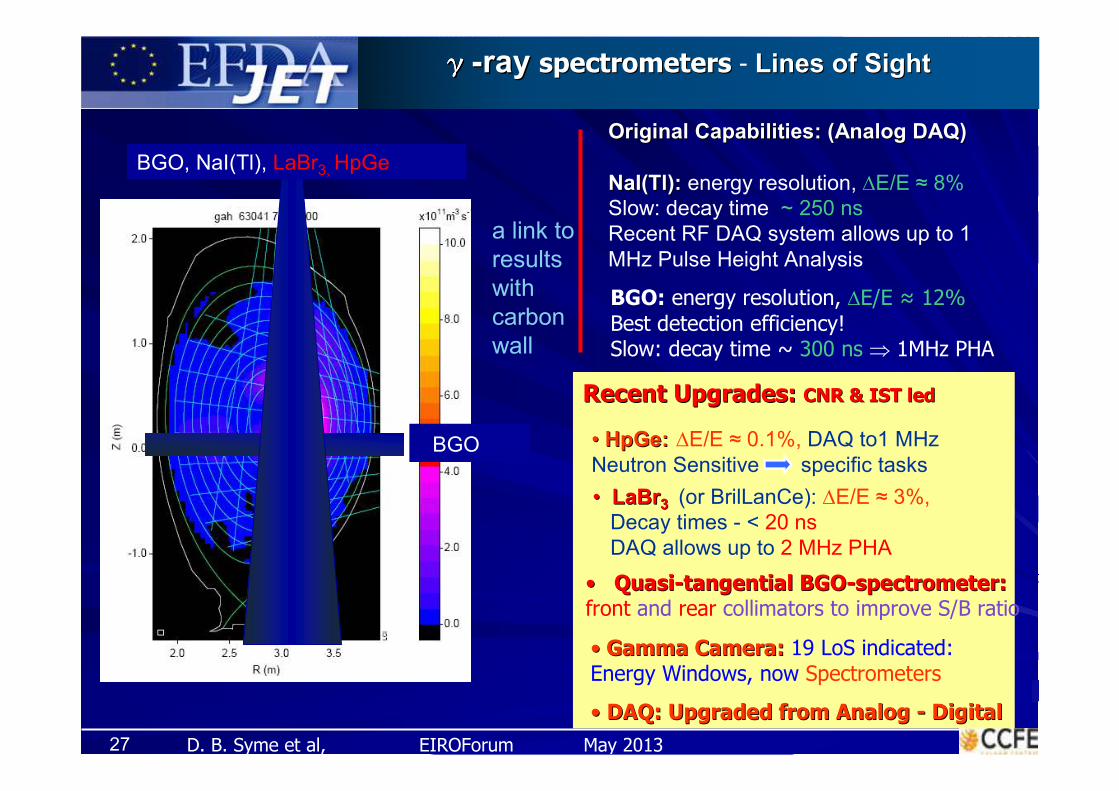
γγγγγγγγ--ray ray spectrometersspectrometers - Lines of SightLines of Sight
BGO
Original Capabilities: (Original Capabilities: (AnalogAnalog DAQ)DAQ)
NaI(TlNaI(Tl):): energy resolution, ∆E/E ≈ 8%
Slow: decay time ~ 250 ns
Recent RF DAQ system allows up to 1
MHz Pulse Height Analysis
•• LaBrLaBr33 (or BrilLanCe): ∆E/E ≈ 3%,
Decay times - < 20 ns
DAQ allows up to 2 MHz PHA
•• QuasiQuasi--tangential BGOtangential BGO--spectrometer:spectrometer:front and rear collimators to improve S/B ratio
BGO, NaI(Tl), LaBr3, HpGe
Recent Upgrades: Recent Upgrades: CNR & IST ledCNR & IST led
BGO: energy resolution, ∆E/E ≈ 12%
Best detection efficiency!Slow: decay time ~ 300 ns ⇒ 1MHz PHA
a link to
results
with
carbon
wall
•• HpGeHpGe:: ∆E/E ≈ 0.1%, DAQ to1 MHz
Neutron Sensitive specific tasks
•• Gamma Camera:Gamma Camera: 19 LoS indicated: Energy Windows, now Spectrometers
•• DAQ: Upgraded from DAQ: Upgraded from AnalogAnalog -- DigitalDigital

D. B. Syme et al, EIROForum May 201328
GammaGamma--Ray Spectrometers Ray Spectrometers -- Vertical Vertical LoSLoS
Neutronattenuators
Sliders
LaBr3
NaI(Tl)
HpGe
(a)
Concrete
shielding
Precollimator
TOFOR
Coils Horizontal
diagnostic
port
Upper vertical
diagnostic port
Support structure
and radiation shielding
Divertor region
Roof
laboratoryJG09.419-3a
3 Detectors and 2 neutron filters on sliders - Choose 1 & switch into the N/G beam
BGO or LaBr3 above 6LiH Filter in 2nd vertical path (not shown)
G Specs
D. B. Syme et al, EIROForum May 201329
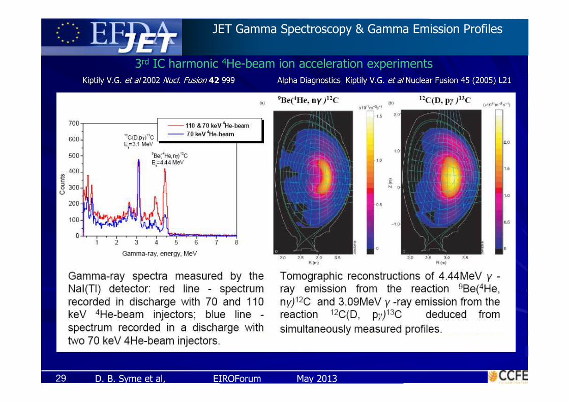
JET Gamma Spectroscopy & Gamma Emission Profiles
Kiptily V.G. Kiptily V.G. et al et al 2002 2002 NuclNucl. Fusion . Fusion 42 42 999999 Alpha Diagnostics Alpha Diagnostics Kiptily V.G. Kiptily V.G. et al et al Nuclear Fusion 45 (2005) L21Nuclear Fusion 45 (2005) L21
3rd IC harmonic 4He-beam ion acceleration experiments

D. B. Syme et al, EIROForum May 2013
0 2 4 6 8 10 12 14 16 18 200
50
100
150
200
250
verticalhorizontal
Co
un
ts
Channel number
#81852
0 2 4 6 8 10 12 14 16 18 20
0
100
200
300
400
500
600
700
Coun
ts
Channel number
Gamma-ray background count rates
during NBI heating phase
in ## 81852,81853, 81855 & 81857
γγ--rayray emission profile from Gamma Cameraemission profile from Gamma Camera
Be-profile is needed to obtain the spatial distribution of energetic ions
NBI phase ICRH phase
Digital DAQ by IST Association
(From spectroscopic data obtained with the(From spectroscopic data obtained with the new digital DAQ)new digital DAQ)
D. B. Syme et al, EIROForum May 2013
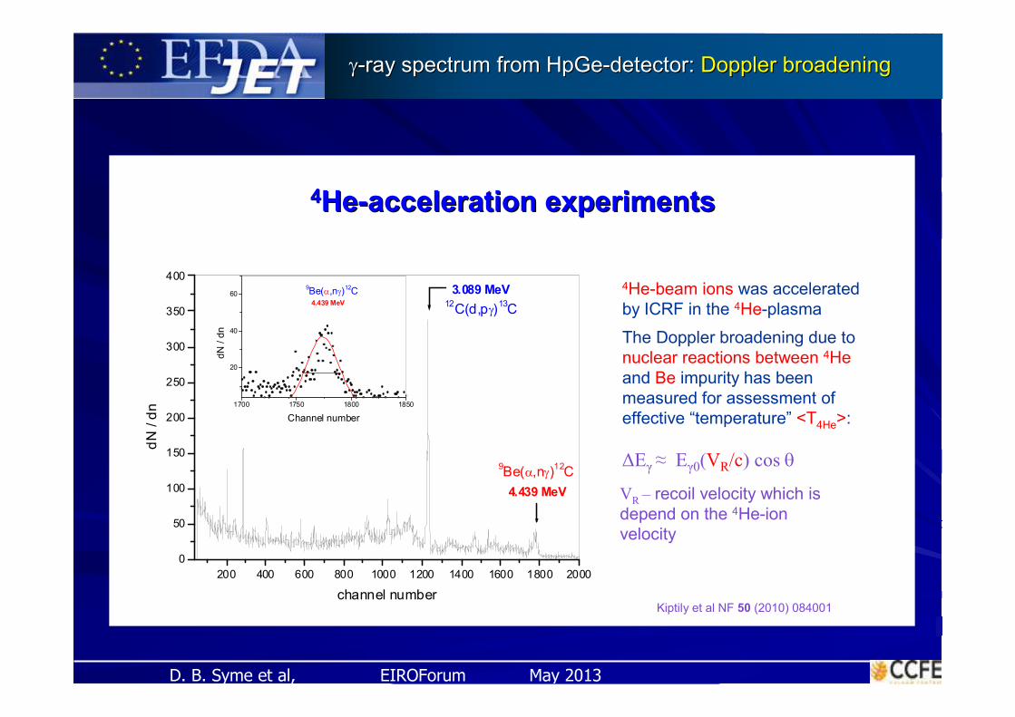
200 400 600 800 1000 1200 1400 1600 1800 2000
0
50
100
150
200
250
300
350
400
12C(d,pγ)
13C
9Be(α,nγ)
12C
3.089 MeV
4.439 MeV
dN
/ d
n
channel number
1700 1750 1800 1850
20
40
609Be(α,nγ)
12C
4.439 MeV
dN
/ d
n
Channel number
Kiptily et al NF 50 (2010) 084001
4He-beam ions was accelerated
by ICRF in the 4He-plasma
The Doppler broadening due to
nuclear reactions between 4He
and Be impurity has been
measured for assessment of
effective “temperature” <T4He>:
∆Eγ ≈ Eγ0(VR/c) cos θ
VR – recoil velocity which is
depend on the 4He-ion
velocity
γγ--ray ray spectrum from HpGespectrum from HpGe--detector: detector: Doppler broadeningDoppler broadening
44HeHe--acceleration experimentsacceleration experiments

D. B. Syme et al, EIROForum May 2013
γγγγγγγγ--ray ray spectrum from spectrum from HpGeHpGe--detectordetector : fast a-particle beam
32
E* = 6 MeV
Shape does change with E*
Limited by statistics
Eα = 3 MeV
R
4MeV α
LOS ICRH
2MeV α
Spectrometer
M. Tardocchi et al, proceeding of EPS conference, Dublin, June 2010
M. Nocente et al, Nuclear Fusion 52 (2012)022001
kp in agreement with values found from
analysis of peaks from 12C(d,pγγγγ)13C
D. B. Syme et al, EIROForum May 201333
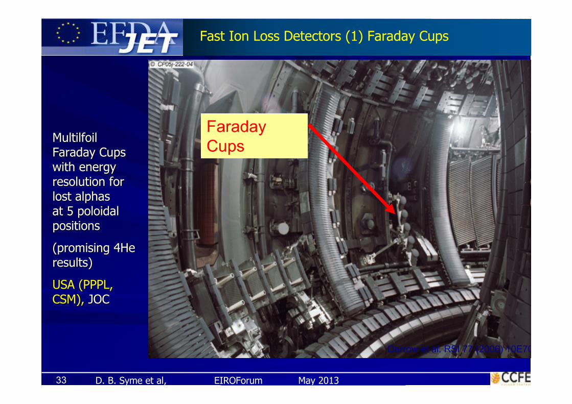
Faraday
Cups
Darrow et al. RSI 77 (2006) 10E701
Fast Ion Loss Detectors (1) Faraday Cups
MultilfoilMultilfoil
Faraday Cups Faraday Cups
with energy with energy
resolution for resolution for
lost alphas lost alphas
at 5 poloidal at 5 poloidal
positionspositions
(promising 4He (promising 4He
results)results)
USA (PPPL, USA (PPPL,
CSM), CSM), JOCJOC

D. B. Syme et al, EIROForum May 201334
Faraday Cups array provides good poloidal and time resolution
• Time resolution: 1 kHz
• Multiple poloidal positions (5)
• Multiple radial locations (max 3)
• BUT, no pitch angle resolution
Also
• Detector composed of multiple thin metal foils separated by mica foils
• Ion energy determines deposition depth
• Ion current measured for each foil individually
• Current vs depth gives energy distribution (∆E~30–50%)
Moderate Energy Resolution (max 8 bins)
Fast Ion loss Detectors (1) Faraday Cups

D. B. Syme et al, EIROForum May 201335
Scintillator Probe
Location: Octant 4 lower limiter guide tube
Fast Ion Loss Detectors (2) Scintillator Probe
USA (PPPL, CSM), JOC
D. B. Syme et al, EIROForum May 201336
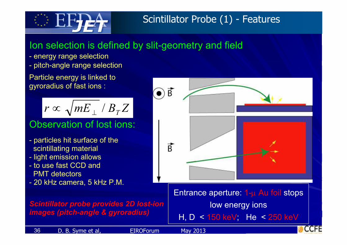
- energy range selection
- pitch-angle range selection
Particle energy is linked to
gyroradius of fast ions :
Observation of lost ions:
- particles hit surface of the scintillating material
- light emission allows - to use fast CCD and
PMT detectors- 20 kHz camera, 5 kHz P.M.
Ion selection is defined by slit-geometry and field
Entrance aperture: 1-µ Au foil stops
low energy ions
H, D < 150 keV; He < 250 keV
ZBmErT
/⊥∝
Scintillator probe provides 2D lost-ion images (pitch-angle & gyroradius)
Scintillator Probe (1) - Features

D. B. Syme et al, EIROForum May 2013
Scintillator Probe (2) – Main project activities

D. B. Syme et al, EIROForum May 201338
Scintillator Probe (3) – Data Visualisation
D. B. Syme et al, EIROForum May 201339
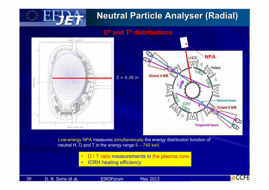
Neutral Particle Analyser (Radial) Neutral Particle Analyser (Radial)
DD00 and Tand T00 distributionsdistributions
Z = 0.28 m A
B
C
D
Low-energy NPA measures simultaneously the energy distribution function of
neutral H, D and T in the energy range 5 – 740 keV.
• D / T ratio measurements in the plasma core
• ICRH heating efficiency
NPA

D. B. Syme et al, EIROForum May 201340
R = 3.07 m
A
B
C
D
High-Energy NPA measures the energy distribution function of neutral H, D, T, 3He and 4He in the energy range 0.3 – 4 MeV.
Si-detectors now installed for better distinguishing D and α’s!
NPA
Neutral Particle Analyser (Vertical)Neutral Particle Analyser (Vertical)
Vertical LoS

D. B. Syme et al, EIROForum May 2013
How NPA worksHow NPA works
Neutralisation in plasmaNeutralisation in plasma
Ionisation by carbon foil Ionisation by carbon foil
(~30 nm)(~30 nm)
Acceleration (horizontal)Acceleration (horizontal)
MomentumMomentum--energy energy
separation (B, E)separation (B, E)
Detection (in 2D array of Detection (in 2D array of
CsI or Si)CsI or Si)
Data acquisitionData acquisition
+HV
B
EC foil
Atoms
CsI(Tl) scintillator+ PMT detectors
JET
E deflection is used to select the particle
D. B. Syme et al, EIROForum May 2013
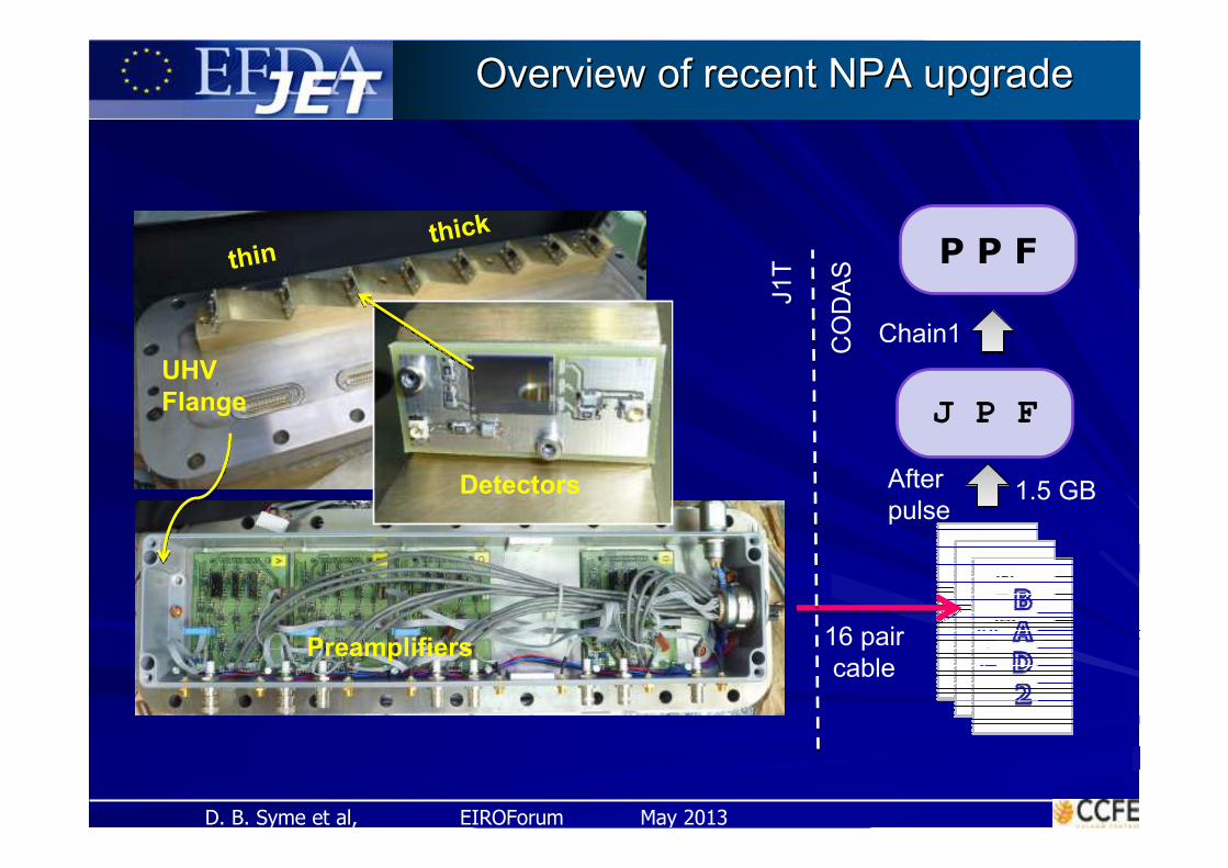
Overview of recent NPA upgradeOverview of recent NPA upgrade
Detectors
UHV
Flange
Preamplifiers 16 pair
cable
thinthick
J P F
After
pulse
P P F
Chain1
J1T
CO
DA
S
1.5 GB

D. B. Syme et al, EIROForum May 2013
Raw Data from the NPA Si detectorsRaw Data from the NPA Si detectors
n only n+ions ions only
Vertical: Energy, Horizontal: Time through JET pulse (3 conditions)
Bottom 2 Plots are Power in the pulse (NBI & ICRH) and Neutron output

D. B. Syme et al, EIROForum May 201344
Summary: Current JET Fast Ion Diagnostics Systems
SystemsSystems JET DetectorJET Detector CapabilitiesCapabilities
Lost Ions:
Time-resolved charged
particle analysers
Faraday cupsMultifoils, 5 Poloidal angles
Fast Ion losses: fast
response, low E resn,>300/850 keV, H,D/He
Scintillator ProbeTG-Green, CCD & PM arrays
Confined Ions:
Gamma Emission
Profile Monitor
(2D-cameras)
Gamma Camera:CsI Scintillators
Fast Ion spatial
distributions via:
Gamma Emission Profiles & Tomography, EG 0.6-6 MeV
Confined Ions:
Gamma Spectrometers
Horizontal View: BGO
Vertical View:NaI, LaBr3, HpGe
Fast ion energy distribution
(NBI and ICRH heating)
By Gamma Emission Spectra>50/900/1700 keV for H,D/3He/4He
Fast Ion losses: vs E
range & pitch angle >300/850 keV, H,D/He
Horizontal* & Vertical
NPAs: C, ExB, CsI
Fluxes of neutrals by:Energy, Species
Neutral Particles:
Time-resolved neutral
particle analysers

D. B. Syme et al, EIROForum May 2013
The EndThe End
JET Neutron, Gamma & Particle DiagnosticsJET Neutron, Gamma & Particle Diagnostics