jnfl sub-surface disposal plan and safety strategy for relatively higher llw kazuyuki kato japan...
TRANSCRIPT

JNFL Sub-Surface Disposal Plan and Safety Strategy for Relatively Higher LLW
Kazuyuki KATOJapan Nuclear Fuel Limited
(JNFL)
Technical Meeting on the Disposal of ILWSeptember 9-13, 2013
Vienna, IAEA

Contents
Classification of radioactive waste disposal
Basic concept of sub-surface disposal
Target waste and facility design activity
Safety strategy for sub-surface disposal
2
3
Classification of Radioactive Waste Disposal
4
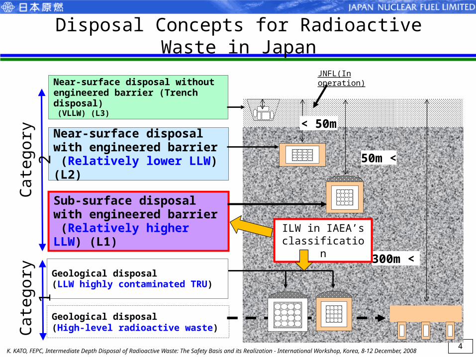
Disposal Concepts for Radioactive Waste in Japan
300m <
Sub-surface disposal with engineered barrier (Relatively higher LLW) (L1)
Near-surface disposal with engineered barrier (Relatively lower LLW) (L2)
Near-surface disposal without engineered barrier (Trench disposal) (VLLW) (L3)
Geological disposal(High-level radioactive waste)
Geological disposal (LLW highly contaminated TRU)
50m <
< 50m
K. KATO, FEPC, Intermediate Depth Disposal of Radioactive Waste: The Safety Basis and its Realization - International Workshop, Korea, 8-12 December, 2008
JNFL(In operation)
Cat
egor
y 1
Cat
egor
y 2
ILW in IAEA’s classification

5
VLLW Relatively lower LLW Relatively higher LLW
(L3) (L2) (L1)
Disposal Depth Near-surface: < 50m Sub-surface: 50m <
Engineered BarrierSystem (EBS)
without EBS with EBS with High Performance EBSTrench Concrete pit
Active control period ~50 years ~300-400 years
Upper Bound
s of Concentratio
n(Bq/ton-
waste)
C-14 - 1E+11 1E+16
Cl-36 - - 1E+13
Co-60 1E+10 1E+15 -
Ni-63 - 1E+13 -
Sr-90 1E+07 1E+13 -
Tc-99 - 1E+09 1E+14
I-129 - - 1E+12
Cs-137 1E+08 1E+14 -
alpha - 1E+10 1E+11
Upper Bounds of Radioactive Concentration for Burial of Low-Level Radioactive Solid Waste (in Japanese), NSC, May 2007.
Upper Bounds of Concentration for each LLW Disposal Concept

6
Basic Concept of Sub-Surface Disposal

7
Regulatory Requirement for Disposal Depth
0m
20 m
40 m
Foundation of
ordinary house
Foundation of high
rise building and
its basementsubway
Water
pipe
sewerage
underground
multipurpose
duct
Foundation of motorway and train
overpass
Example of sub -surface disposal concept
Sufficient depth against normal use of
underground (ex. 50 -100m).
Tunnel type
Silo type
LLW for sub -
surface disposal
0m
20m
40m
Foundation of ordinary house
Foundation ofHigh-rise buildingAnd basementSubwayWater
pipe
Sewerageunderground multipurpose duct
Example of sub -surface disposal concept
Sufficient depth against normal use of
underground (ex. 50 -100m).
Example of sub-surface disposal concept
Sufficient depth to avoid normal use of underground (e.g. 50-100m).
Tunnel typeSilo type
LLW forSub-surface disposal
The depth of sub-surface disposal is defined over 50m in law

8
(1) Depth Sufficient depth to avoid normal use of underground (over 50m).
(2) Candidate site The place that has the function to prevent or mitigate the migration of the radioactive nuclides to the environment
(3) Disposal facility The function to reduce the flux of radioactive nuclides from the facility is more enhanced than L2
(4) Institutional control Several hundred years until the radioactive nuclides significantly decay
Concept of Sub-Surface Disposal

9
Target Waste and Facility Design Activity

10
NuclearPower Plant
ReprocessingPlant
MOX Fuel Fabrication Plant
Recovered Uranium/PlutoniumSpent FuelUranium Fuel
MOX Fuel
Low-level wasteLow-level waste High-levelwasteHigh-levelwaste Low-level wasteLow-level waste
・ Concrete pit Disposal(L2)・ Trench Disposal (L3)
Concentrated liquid waste
Incombustibles
Inflammables
Incombustibility thing
Metallic piping, Plastic material
Channel box(CB)
Burnable poison(BP)
- BWR - - PWR -
Control Rod
(Reactor core internal etc.)
Sub-surface Disposal (L1)
( Note ) CB/BP are generated from not only the power stations but also a reprocessing plant.
Ionexchangeresin
・ Geological Disposal ( vitrified waste, hull, end-piece )
Target Waste for Sub-Surface Disposal
Uranium Enrichment Plant/Fuel Fabrication Plant
Control Rod

11
Time after generation [y] Time after generation [y]
Operational waste from power station (activated metal)
Waste from JNFL (Reprocessing Plant and MOX Plant)Source: NSC: Figure 1, Figure 4, Document No. 11-1, Sub-committee on Category 2 Waste Disposal 11th Meeting, Special committee on Radioactive waste/Decommissioning (2008)
[Bq/ton]
[Bq/ton]
Ra
dio
act
ive
co
nce
ntr
atio
n
Ra
dio
act
ive
co
nce
ntr
atio
n
Ni-63
C-14
Ni-59
Zr-93
Ni-63
C-14
Ni-59Zr-93
Example of the Waste Inventory for Sub-Surface Disposal

Objectives of Site Investigation in Rokkasho 沼経路-沼産物摂取
沢経路-沢水飲用
沢水飲用畜産物摂取
沢水灌漑農耕
ベントナイト
廃棄物
施設浸入水
沢および沼
溶出率
(黒鉛・放射化物)
廃棄体層(均一混合)
移流・分散
GL-100m
拡散
コンクリート(バリア機能無視)低拡散バリア
拡散
クラック
クラック
ヘアークラック
9割:沼に直接移行1割:沢 を経由して
沼に移行
沢
一部
大半
1次元移流分散
沼経路-沼産物摂取
沢経路-沢水飲用
沢水飲用畜産物摂取
沢水灌漑農耕
ベントナイト
廃棄物
施設浸入水
沢および沼
溶出率
(黒鉛・放射化物)
廃棄体層(均一混合)
移流・分散
GL-100m
拡散
コンクリート(バリア機能無視)低拡散バリア
拡散
クラック
クラック
ヘアークラック
9割:沼に直接移行1割:沢 を経由して
沼に移行
沢
一部
大半
1次元移流分散地下水の浸入
② 地下水調査 ・地下水の流れる速さ ・地下水の流れる方向
③ 地盤調査 空洞の安定性確認
地下水の流れ
高透水層(地下水が流れやすい箇所)
① 地質調査 断層、割目の有無確認
沼100m程度
沢
2) Groundwater -Hydraulic characteristics -Geochemical characteristics
3) Rock mechanics Stability of cavern Permeable zone
1) Geology -Geological structure -Properties of faults/fractures
stream
Approx.100m
marsh
12

Exploratory drift(for accessing)
6.5 m
7 m
Entrance
16 m
18 m
Test cavern
Test Cavern and Exploratory Drifts
13

14
The difference of EBS performance
T. Shimizu, The Fourth Annual RadWaste Summit, September 7-10, 2010, Las Vegas, Nevada
10-15 10-10 10-510-15
10-10
10-5
Hydraulic Conductivity Kw [m/s]
Effe
ctiv
e D
iffus
ion
Coe
ffici
ent
De
[m2 /
s] Near-surface disposal(in operation)
Sub-surface disposal

15
Engineered Barrier System of Sub-Surface Disposal
Bentonite
Mortar
Reinforced concrete pit
Backfill (soil, concrete)
Liner concrete
Waste packages
Host Rock(sedimentary rock)
Mortar fill
(Low permeability layer)
(Low diffusivity layer)
approx. 18 m

16
Structure of sub-surface disposal facility
Disposal Facility Cross section Disposal Facility Profile
Approx. 18 m
Appro
x.
18
m
Approx. 13 m
Appro
x.
12
mApprox. 14 m
Support / Secondary Lining
Low permeability layer
Filler
Waste packages
Concrete pit
Low diffusivity layer
Backfill material
K. KATO, FEPC (2008)

17
把持ガイド
廃棄物
追加遮へい体
蓋
本体
Size : 1.6m L ×1.6m W ×1.6m H (some are 1.2m H) Material : Carbon Steel (SM400 etc.)Weight : approx. 28 ton (Max, including inner shield, waste)
Lid
Additional shield
Waste
Main body of the waste package Handling guide
Structure of the Waste Package (conceptual view)

18
Safety Strategy For Sub-Surface Disposal

19
[ ]経過時間 年
単位重量当たりの潜在的影響(
相対値)
103 104 105 10610210110- 10
10- 9
10- 8
10- 7
10- 6
10- 5
10- 4
10- 3
10- 2
10- 1
1
放射性廃棄物の潜在的影響の経時変化の比較) 1 1(高レヘ ル゙放射性廃棄物(カ ラ゙ス固化体 の 年目を とした相対値)
( (出典:原子力安全委員会資料より一部編集))
高レベル放射性廃棄物
余裕深度処分対象廃棄物
コンクリートピット処分対象廃棄物
[ ]経過時間 年
単位重量当たりの潜在的影響(
相対値)
103 104 105 10610210110- 10
10- 9
10- 8
10- 7
10- 6
10- 5
10- 4
10- 3
10- 2
10- 1
1
放射性廃棄物の潜在的影響の経時変化の比較) 1 1(高レヘ ル゙放射性廃棄物(カ ラ゙ス固化体 の 年目を とした相対値)
( (出典:原子力安全委員会資料より一部編集))
高レベル放射性廃棄物
余裕深度処分対象廃棄物
コンクリートピット処分対象廃棄物
L1 waste(sub-surface disposal)
Vitrified HLW (geological disposal)
Change of potential risk of radioactive wastes(relative risk to the initial risk of vitrified HLW)
(reference from NSC document (modified))
L2 waste(near surface disposal)(“pit disposal”)
Potential risk (effect) per unit mass(relative risk)
Time (year)
Safety Issues and Time-Frame for L1 waste
Institutional Control until significant decay
Consideration for very long-term safety
Multi-barrier System for slow migration

Key Issues on Safety Assessment of Sub-Surface Disposal (Intermediate Depth Disposal)
1. Peak dose rate of ground water scenario must be lowered below regulatory limit by multi-barrier system.
2. Sufficient inaccessibility to the biosphere for a long time
3. Even if separation to the biosphere would be lost after very long time, public should be protected safely from the risk of radiation exposure.
Concerning 1 and 2,Future geological environment could be estimated with enough
accuracy, and would be stable for long time. Accordingly, for this time frame, the separation to biosphere would be sufficient and the key scenario would be the migration in underground water. For this evaluation, degradation of engineered barriers should be considered appropriately.
Concerning 3,For this time frame, functions of engineered barriers could not be
expected, the effects according with the decrease of depth, such as increase of water flow velocity, should be considered appropriately.
20

21
Safety strategy
Multiple countermeasures may be necessary for a certain radionuclide in different cases.
C-14
Cl-36, I-129
Applicable to only limited period⇒ Depending on facility design / siting
Judgement of necessity of additional barriers
What kind of composition is necessary?Depending on facility design⇒
Siting / Composition of barriers
Avoidance by siting
option
option
option
Underground disposal (Isolation and Shielding to the biosphere are expected) 地中処分( 地中処分という概念自体が生活環境に対する離隔の確保としゃへい )に期待したもの
postclosureperiod
Naturalprocess
Groundwatermigration
Relatively short-lived
Concentration/containment
preventing groundwater contact with waste packages
Retardation
Retardation by NBS
Retardation by EBS
Relatively long-lived
Dilution /dispersion Spatial dilusion
Dilusion by water
Dispersion of source
Temporal dilusion
Restricting inventory / concentration
Gas migration
Relative movement by uplift/erosion
Relatively short-lived
Relatively long-lived
Very unlikely natural processHuge Earthquakes/fault movement
Volcanic/igneous activities
human intrusion
operational period
key RN : C-14, Cl-36, Ni-59, Tc-99, Zr-93, Nb-94, I-129, alpha ..
Ni-59,Nb-94,alpha

22
Key Issues for multi-barrier system of Sub-Surface Disposal
Key nuclides in groundwater scenario are C-14 and Cl-36. Because of its long half-life, only the retardation function by the natural barrier may not be sufficient.In the intermediate depth, Reducing condition of groundwater may not be expected Groundwater velocity is generally slower than that of near
surface/shallow disposal facility, but groundwater velocity is faster than that of geological disposal facility.
Both low permeability and low diffusivity would be expected for a long time to assure high retardation performance.The design of engineered barriers should be considered appropriately the site characteristics and waste characteristics.

23
How deep is safe enough?
Even after very long time, effect of the radioactivity is not negligible. Even if separation to biosphere would be lost, safety of public should be assured. If the site characteristics shows uplift tendency, the
disposal facility should be initially located at appropriate depth to keep sufficient separation for a long time considering uplift and erosion.
Based on expected time that the disposal facility would have exposed, the volume and concentration of radioactive waste to be disposed should be limited to assure the safety of public.
24
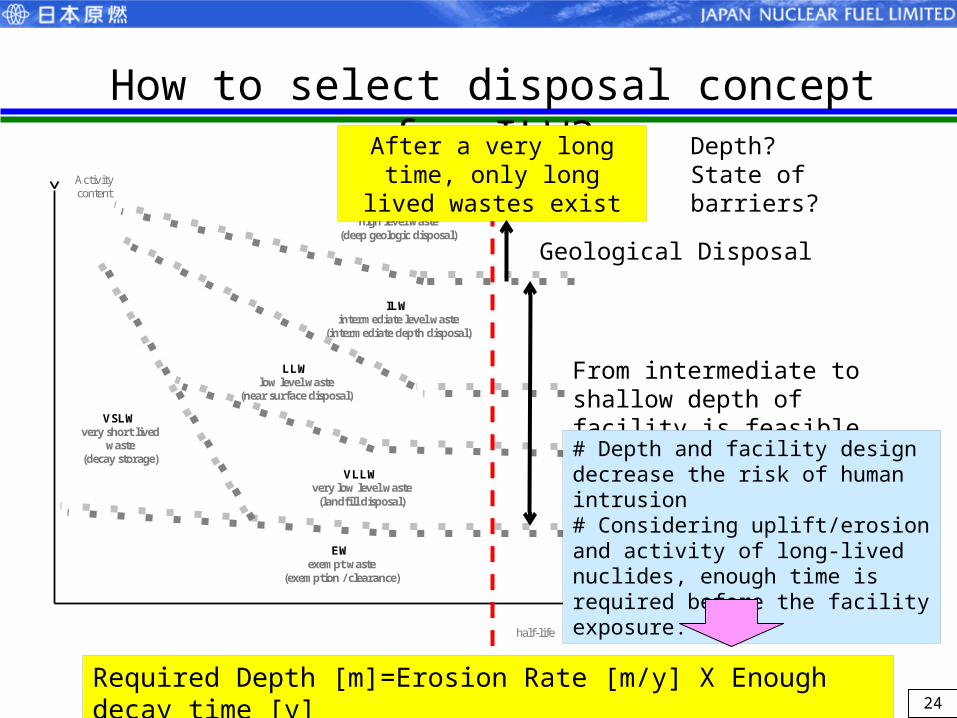
half-life
Activity content
VSLW very short lived
waste (decay storage)
HLW high level waste
(deep geologic disposal)
ILW intermediate level waste
(intermediate depth disposal)
LLW low level waste
(near surface disposal)
VLLW very low level waste
(landfill disposal)
EW exempt waste
(exemption / clearance)
How to select disposal concept for ILW?After a very long time, only
long lived wastes exist
Geological Disposal
From intermediate to shallow depth of facility is feasible
# Depth and facility design decrease the risk of human intrusion# Considering uplift/erosion and activity of long-lived nuclides, enough time is required before the facility exposure.
Depth?State of barriers?
Required Depth [m]=Erosion Rate [m/y] X Enough decay time [y]
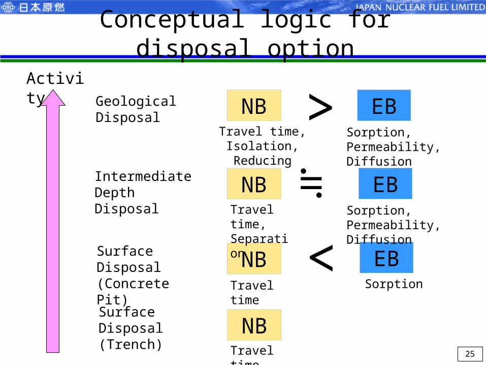
Conceptual logic for disposal option
25
NB EBActivity
GeologicalDisposal
Intermediate DepthDisposal
Surface Disposal (Concrete Pit)
Surface Disposal (Trench)
>NB EB≒
NB EB
>
NB
Sorption
Sorption, Permeability, Diffusion
Travel time
Travel time,Separation
Travel time,Isolation, Reducing
Sorption, Permeability, Diffusion
Travel time

26
Required scenario & target dose
Scenario category
Sub-scenarios Target dose per RMEI
Natural process
Likely scenarios
Groundwater scenarioGas migration scenarioLand use scenario
0.01 mSv/yr
Less-likely scenarios
Groundwater scenarioGas migration scenarioLand use scenario
0.3 mSv/yr
Very unlikely scenarios
Earthquakes/Fault movementVolcanic/Igneous activity
10~100 mSv/yr
Human intrusionBorehole scenariosTunnel excavation scenariosA large-scale land use scenario
Residents: 1~10 mSv/yrIntruder: 10~100 mSv
RMEI : Reasonably Maximally Exposed Individual
BASIC GUIDE
NSC Japan, August 2010
A new regulatory framework is under discussion among regulatory authorities in response to the Fukushima Daiichi NPP accident.

Conclusion
Relatively higher LLW (ILW) would be disposed at tunnel type facility of intermediate depth in Japan.
In both design and safety assessment of the facility, complementary and reasonable performance between natural barrier and engineered barrier should be considered.
Sufficiency of initial depth should be evaluated by the safety assessment when the disposal facility would have exposed. The volume and concentration of radioactive waste to be disposed should be limited based on the result of safety assessment.
Logics to show the safety of ILW disposal should be clarified.
27

28
Thank you for your attention!
END