john deere 4045 & 4038 scale system · 2019-04-18 · the john deere 4045 fertilizer spreader...
TRANSCRIPT

7600905 REVB
JOHN DEERE 4045 & 4038
Scale System
Installation Instructions
And
Repair Parts

TABLE OF CONTENTS
7600905 REVB P a g e | 1
Anamosa, Iowa USA
TABLE OF CONTENTS
INTRODUCTION ............................................................................................................................................. 3
Charging Battery and Welding .................................................................................................................. 3
SCALE BRACKET AND LOAD CELL MOUNTING INSTALLATION ...................................................................... 4
Scale Installation ....................................................................................................................................... 4
Spreader Box Removal .......................................................................................................................... 4
Lifting the Spreader Box ........................................................................................................................ 6
Expanding the Rear Box Mount Flanges ............................................................................................... 6
Remove Tiedowns ................................................................................................................................. 7
Installation of Load Cells ....................................................................................................................... 8
Tightening Hardware .......................................................................................................................... 24
Greese Application .............................................................................................................................. 31
JUNCTION BANK MOUNTING ................................................................................................................... 32
DT06 Junction Bank .............................................................................................................................. 32
INDICATOR MOUNTING .............................................................................................................................. 33
RAM MOUNT........................................................................................................................................... 33
TESTING AND TROUBLE SHOOTING ............................................................................................................ 34
Inaccurate weights? ................................................................................................................................ 34
Erratic weights?....................................................................................................................................... 34
OPERATING THE SCALE ............................................................................................................................... 35
Filling the Spreader ................................................................................................................................. 35
Monitoring your application rate............................................................................................................ 35
REPAIR PARTS .............................................................................................................................................. 36
Maintenance Requirements ....................................................................................................................... 41
25 hour Maintenance.............................................................................................................................. 41
100 hour Maintenance ........................................................................................................................... 41

TABLE OF CONTENTS
7600905 REVB P a g e | 2
THIS PAGE HAS BEEN INTENTIONALLY LEFT BLANK

INTRODUCTION
7600905 REVB P a g e | 3
INTRODUCTION Congratulations on the purchase of your new scale system for your John Deere r4045 Dry Applicator. This scale system is specifically designed to weigh the New Leader box on a John Deere r4045 chassis. The scale system can be used to keep inventory of product and make in field calibration adjustments.
This SAFETY ALERT SYMBOL indicates important safety messages in the manual. When you see this symbol, be alert to the possibility of PERSONAL INJURY and carefully read the message that follows.
NEVER OPERATE WITHOUT ALL COVERS, SHIELDS AND GUARDS IN PLACE. KEEPHANDS, FEET AND CLOTHING AWAY FROM MOVING PARTS. FAILURE TO HEED MAY RESULT INSERIOUS PERSONAL INJURY OR DEATH. Some covers and guards have been removed for illustrative/photographic purposes only in this manual.
For information on ordering repair parts, refer to Parts Section in this book.
This supersedes all previous published instructions.
IMPORTANT!
Charging Battery and Welding Disconnect all cables from the weighing indicator before charging the battery or welding on the machine. If cables are left connected, the weighing indicator and connected load cells could be damaged. Important: Do not weld near indicator, load cells or cables; remove from area to be welded. Place ground close to area to be welded to prevent current from passing through electronic parts.
Scale Installation
7600905 REVB P a g e | 4
SCALE BRACKET AND LOAD CELL MOUNTING INSTALLATION
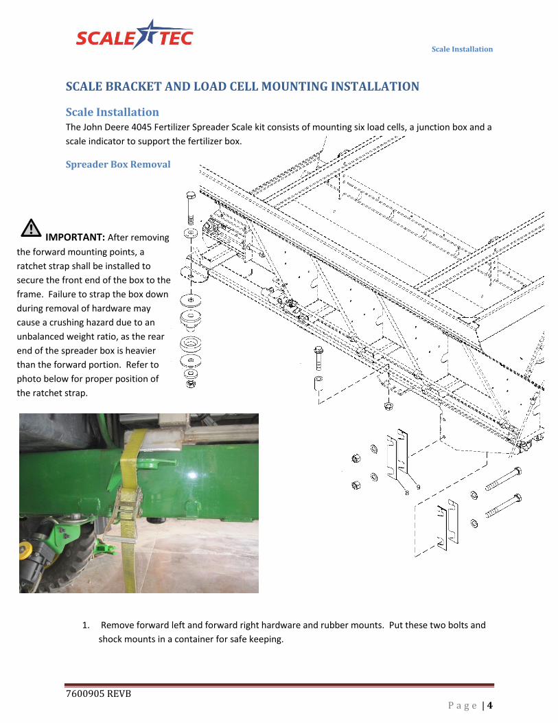
Scale Installation The John Deere 4045 Fertilizer Spreader Scale kit consists of mounting six load cells, a junction box and a
scale indicator to support the fertilizer box.
Spreader Box Removal
1. Remove forward left and forward right hardware and rubber mounts. Put these two bolts and
shock mounts in a container for safe keeping.
IMPORTANT: After removing
the forward mounting points, a
ratchet strap shall be installed to
secure the front end of the box to the
frame. Failure to strap the box down
during removal of hardware may
cause a crushing hazard due to an
unbalanced weight ratio, as the rear
end of the spreader box is heavier
than the forward portion. Refer to
photo below for proper position of
the ratchet strap.

Scale Installation
7600905 REVB P a g e | 5
2. Remove the two bolts securing the center. Keep remainder hardware for safe keeping.
3. Remove the hardware and retaining plates that secures the rear portion of the spreader
box to the chassis of the r4045. It will be necessary to remove both the hardware and
the plates.
5. Remove the backup alarm located on the right axle and disconnect the electrical
connector from the alarm. NOTE: do not discard the hardware, you will need to retain
the hardware for mounting the alarm in a later step.
4. Remove the two inner bolts located on the
rear portion of the left and right axles as
identified with “Letter A” in the figure to the left.
Scale Installation
7600905 REVB P a g e | 6
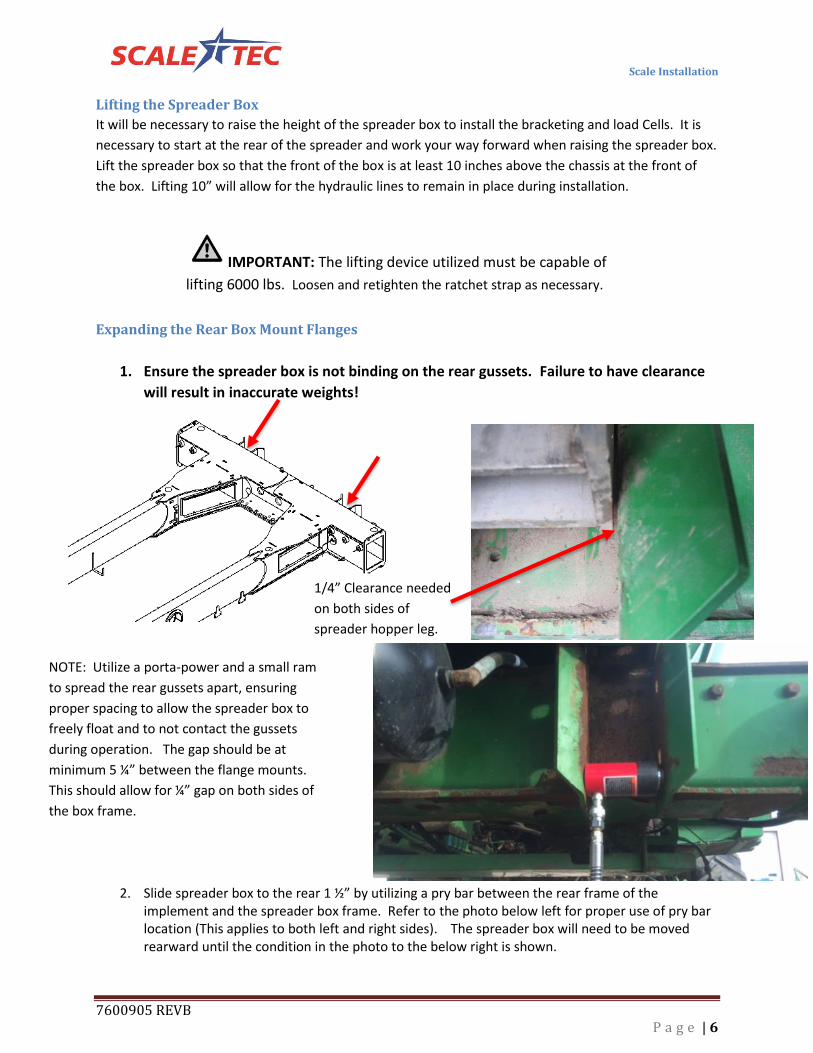
1/4” Clearance needed
on both sides of
spreader hopper leg.
Lifting the Spreader Box
It will be necessary to raise the height of the spreader box to install the bracketing and load Cells. It is
necessary to start at the rear of the spreader and work your way forward when raising the spreader box.
Lift the spreader box so that the front of the box is at least 10 inches above the chassis at the front of
the box. Lifting 10” will allow for the hydraulic lines to remain in place during installation.
Expanding the Rear Box Mount Flanges
1. Ensure the spreader box is not binding on the rear gussets. Failure to have clearance
will result in inaccurate weights!
2. Slide spreader box to the rear 1 ½” by utilizing a pry bar between the rear frame of the implement and the spreader box frame. Refer to the photo below left for proper use of pry bar location (This applies to both left and right sides). The spreader box will need to be moved rearward until the condition in the photo to the below right is shown.
NOTE: Utilize a porta-power and a small ram
to spread the rear gussets apart, ensuring
proper spacing to allow the spreader box to
freely float and to not contact the gussets
during operation. The gap should be at
minimum 5 ¼” between the flange mounts.
This should allow for ¼” gap on both sides of
the box frame.
IMPORTANT: The lifting device utilized must be capable of
lifting 6000 lbs. Loosen and retighten the ratchet strap as necessary.
Scale Installation
7600905 REVB P a g e | 7
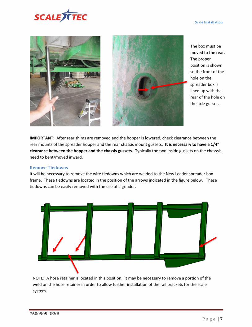
IMPORTANT: After rear shims are removed and the hopper is lowered, check clearance between the
rear mounts of the spreader hopper and the rear chassis mount gussets. It is necessary to have a 1/4”
clearance between the hopper and the chassis gussets. Typically the two inside gussets on the chasssis
need to bent/moved inward.
Remove Tiedowns
It will be necessary to remove the wire tiedowns which are welded to the New Leader spreader box
frame. These tiedowns are located in the position of the arrows indicated in the figure below. These
tiedowns can be easily removed with the use of a grinder.
The box must be
moved to the rear.
The proper
position is shown
so the front of the
hole on the
spreader box is
lined up with the
rear of the hole on
the axle gusset.
NOTE: A hose retainer is located in this position. It may be necessary to remove a portion of the
weld on the hose retainer in order to allow further installation of the rail brackets for the scale
system.
Scale Installation
7600905 REVB P a g e | 8
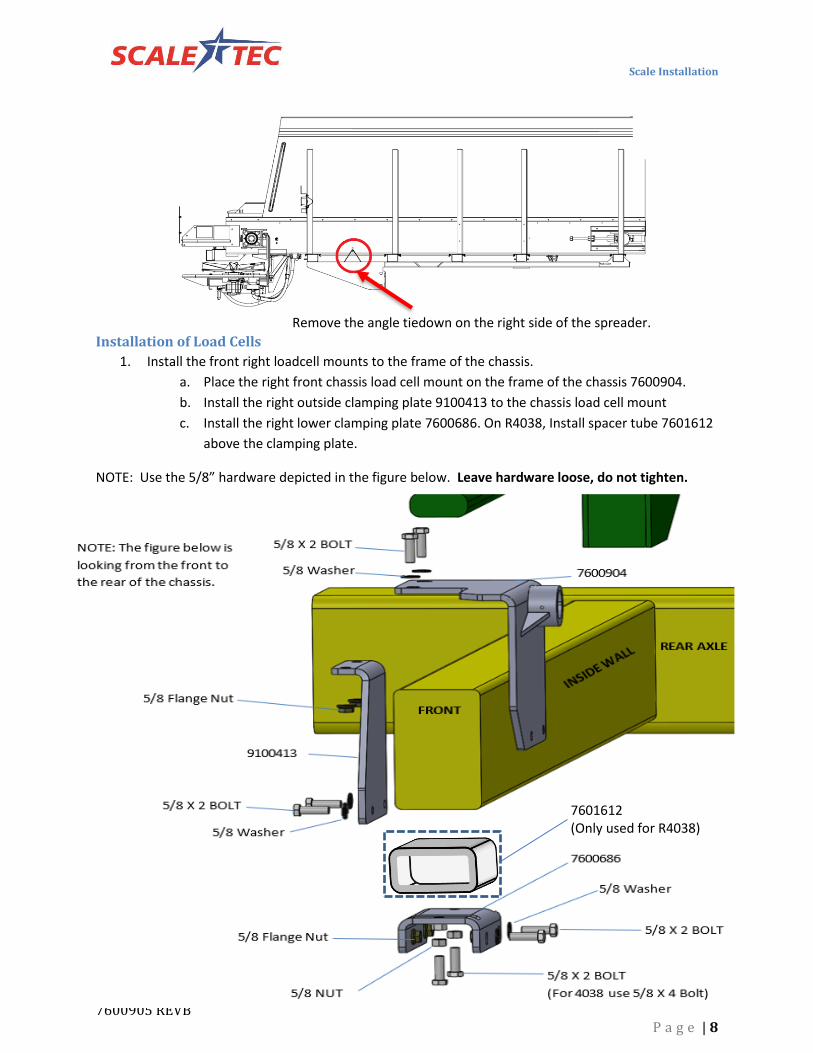
Installation of Load Cells
1. Install the front right loadcell mounts to the frame of the chassis.
a. Place the right front chassis load cell mount on the frame of the chassis 7600904.
b. Install the right outside clamping plate 9100413 to the chassis load cell mount
c. Install the right lower clamping plate 7600686. On R4038, Install spacer tube 7601612
above the clamping plate.
NOTE: Use the 5/8” hardware depicted in the figure below. Leave hardware loose, do not tighten.
Remove the angle tiedown on the right side of the spreader.
NOTE: The figure below is
looking from the front to
the rear of the chassis.
5/8 X 2 BOLT
5/8 Washer
5/8 Flange Nut
9100413
5/8 X 2 BOLT
5/8 Flange Nut 5/8 X 2 BOLT
5/8 X 2 BOLT
(For 4038 use 5/8 X 4 Bolt)
5/8 NUT
5/8 Washer
7600686
7600904
FRONT
5/8 Washer
REAR AXLE
7601612 (Only used for R4038)

Scale Installation
7600905 REVB P a g e | 9
2. Install the front left loadcell mounts to the frame of the chassis.
a. Place the left front chassis load cell mount on the frame of the chassis 7600908.
b. Install the left outside clamping plate 9100418 to the chassis load cell mount
c. Install the front left lower clamping plate 7600685. On R4038, Install spacer tube
7601611 above the clamping plate.
NOTE: Use the 5/8” hardware depicted in the figure below. Leave hardware loose, do not tighten.
5/8 X 2 BOLT
5/8 Washer
5/8 Flange Nut
5/8 X 2 BOLT
5/8 Washer
5/8 Flange Nut
5/8 X 2 BOLT
5/8 Washer
5/8 NUT
5/8 X 2 BOLT
(For 4038 use 5/8 X 4 Bolt)
9100418
7600908
7600685
FRONT
REAR AXLE
NOTE: The figure below is
looking from the front to
the rear of the chassis.
7601611 (Only used for R4038)

Scale Installation
7600905 REVB P a g e | 10
3. Lower the box, resting the box onto the chassis with 2” blocks between the chassis and
the box. NOTE: 2” steel square tube spacers are provided in the kit to aid in
installation.
4. Place the front crossmember (7600654) onto the frame of the spreader box.
a. Ensure the front crossmember (7600654) is positioned and slid forward,
contacting the front edge with the box crossmember.
7600654
FRONT
Scale Installation
7600905 REVB P a g e | 11
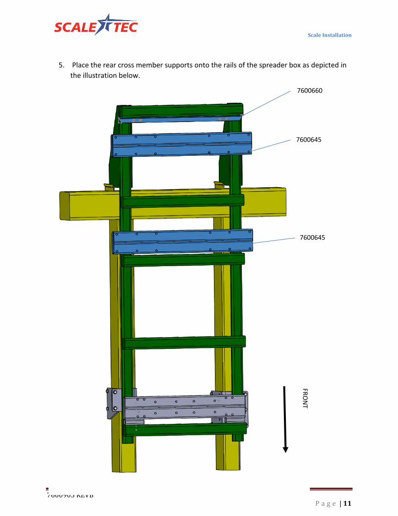
5. Place the rear cross member supports onto the rails of the spreader box as depicted in
the illustration below.
7600645
7600645
7600660 FR
ON
T

Scale Installation
7600905 REVB P a g e | 12
6. Install the front left (7600656) and front right (7600656) rail support brackets to the
front cross member. NOTE: Attention to detail of the figure below and the placement
of the 5/8” bolts. It will be necessary to position the outer bolts from the top down and
inner bolts from the bottom up.
NOTE: Ensure the front left and right rail brackets are flush to the inner spreader box frame.
NOTE: Do not tighten bolts. Leave bolts loose, adjusment may be required for final installation.
5/8 x 5 BOLT
7600656
7600656
5/8 x 5 BOLT
5/8 x 5 BOLT
5/8 x 5 BOLT
5/8 WASHER
5/8 WASHER
5/8 FLANGE NUT
5/8 FLANGE NUT 5/8 WASHER
5/8 FLANGE NUT

Scale Installation
7600905 REVB P a g e | 13
5/8 FLANGE NUT
5/8 x 3 ¼ BOLT 5/8 x 3 ¼ BOLT
5/8 Washer
5/8 Washer 7600650
7600647
7. Install the left rear rail bracket (7600650) and right rear rail bracket (7600647) to the
mid crossmembers (7600645). When securing the rail brackets to the mid crossmember
ensure that you are placing the bolts from the bottom of the bracket towards the top
with the inner most holes on the crossmember bracket. Do not install bolts on the
outer holes, as there are more assemblies required for installation prior to securing with
bolts. See the figure below for more detail.
NOTE: When installing the rear rail mounts, ensure the outside edge with flat 2”x 3/8” steel
plate is flush against the frame of the spreader box.
NOTE: Do not tighten hardware. It will be necessary to make small adjustments in further
steps.

Scale Installation
7600905 REVB P a g e | 14
5/8 Washer
5/8 x 3 ¼ Bolt
5/8 FLANGE
NUT
7600660
5/8 x 1 ½ BOLT
5/8 Washer 5/8 Flange Nut
8. Secure the front and rear rail mounts together with the 5/8” hardware shown in the
figure below.
9. Secure the rear crossmember angle bracket (7600660) to rear rail supports using the
5/8” hardware depicted below. NOTE: Ensure the bolts are installed from the bottom of
the rails through the rear crossmember.
NOTE: Do not tighten hardware, It will be neccesary to make adustments in further steps.

Scale Installation
7600905 REVB P a g e | 15
7600633
400061
¾” Lock Nut
¾” x 4 BOLT
NOTE: It is important the arrow sticker is pointed
toward the channel plate of the mounting bracket.
Failure to do so will result in inaccurate weight
measurement.
10. Assemble the loadcells (400061) with the forward top loadcell mounts (7600633). There
are two of these assemblies provided in the kit.
a. Install the loadcell into the sleeve of the load cell mount.
b. Secure the loadcell with a ¾ x 4” bolt and ¾” lock nut. (Tighten hardware).
c. Ensure when installing the loadcell, the arrow sticker at the end of the load cell
is pointing toward the channel.
NOTE: Apply Anti-Seize agent to the loadcell prior to
inserting it into the sleeve of the loadcell mounting
bracket.

Scale Installation
7600905 REVB P a g e | 16
11. Install the front load cell assemblies to the front crossmember support using the 5/8”
hardware depicted in the figure below.
5/8 x 3 ¼ BOLT
5/8 WASHER
5/8 FLANGE NUT
NOTE: This figure displays mounting it
to the front crossmember, it is also
necessary to position the load cell into
the sleeve of the corresponding chassis
mount bracket. Leave the bolts loose, it
will be neccesary to make adjustments
later.

Scale Installation
7600905 REVB P a g e | 17
12. Install the left rear axle bracket (7600642) onto the top of the axle.
a. Secure the axle bracket to the chassis with two ¾” hardware depicted in the
figure below. Do not tighten this hardware.
13. Secure the rear portion of the left rear axle bracket with the two spacer bushings and
metric bolts depicted below. Do not tighten hardware.
¾” WASHER
¾”x 2 Bolt
¾” WASHER
¾” Lock Nut
7600675 (For 4038 use 7601613)
5/8 Washer
M16 x 90mm BOLT
(For 4038 use M16 x 100mm)
Scale Installation
7600905 REVB P a g e | 18
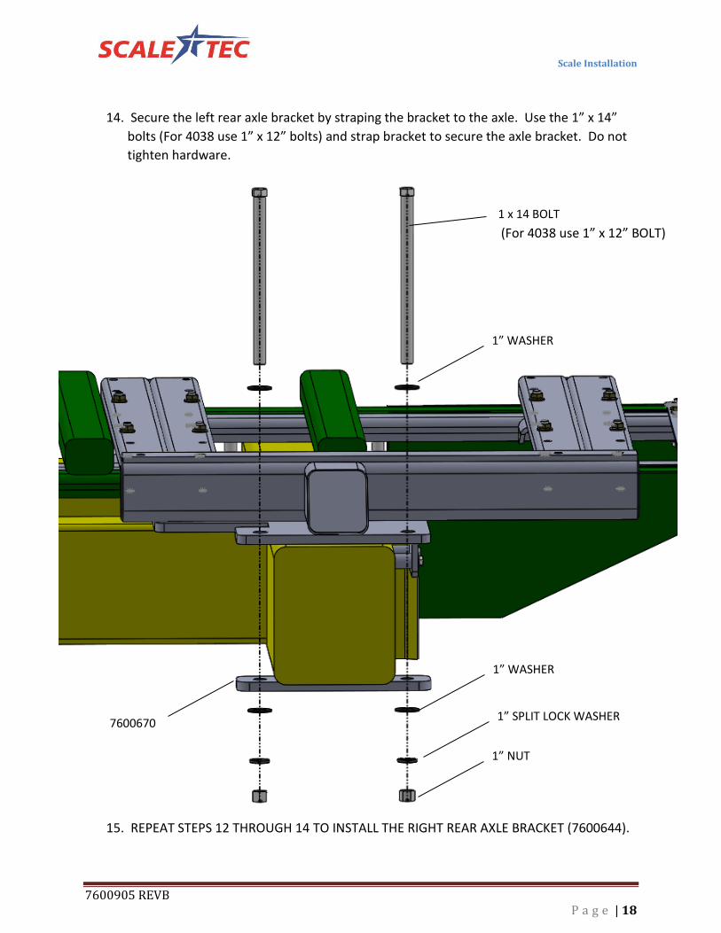
1 x 14 BOLT
(For 4038 use 1” x 12” BOLT)
1” WASHER
1” WASHER
1” SPLIT LOCK WASHER
1” NUT
7600670
14. Secure the left rear axle bracket by straping the bracket to the axle. Use the 1” x 14”
bolts (For 4038 use 1” x 12” bolts) and strap bracket to secure the axle bracket. Do not
tighten hardware.
15. REPEAT STEPS 12 THROUGH 14 TO INSTALL THE RIGHT REAR AXLE BRACKET (7600644).
Scale Installation
7600905 REVB P a g e | 19
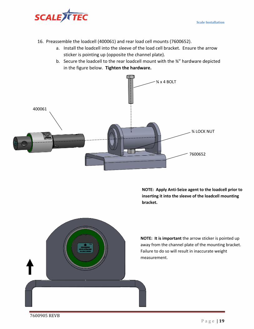
¾ x 4 BOLT
¾ LOCK NUT
400061
7600652
NOTE: It is important the arrow sticker is pointed up
away from the channel plate of the mounting bracket.
Failure to do so will result in inaccurate weight
measurement.
16. Preassemble the loadcell (400061) and rear load cell mounts (7600652).
a. Install the loadcell into the sleeve of the load cell bracket. Ensure the arrow
sticker is pointing up (opposite the channel plate).
b. Secure the loadcell to the rear loadcell mount with the ¾” hardware depicted
in the figure below. Tighten the hardware.
NOTE: Apply Anti-Seize agent to the loadcell prior to
inserting it into the sleeve of the loadcell mounting
bracket.

Scale Installation
7600905 REVB P a g e | 20
17. Install the mid left and right rear load cell assemblies onto the mid crossmember. Use
the 5/8” hardware depicted in the figure below.
NOTE: Do Not Tighten Hardware
5/8 x 3 ¼ BOLT
5/8 WASHER
5/8 FLANGE NUT
5/8 x 5 ¼ BOLT

Scale Installation
7600905 REVB P a g e | 21
18. Install the rear left and right load cell assemblies onto the rear crossmember. Only
secure the rear brackets with the inside 5/8 hardware shown in the figure below.
Further 5/8 hardware will be used in later steps.
NOTE: Do not tighten hardware.
5/8 x 5 ¼ BOLT
5/8 WASHER
5/8 FLANGE NUT
Scale Installation
7600905 REVB P a g e | 22
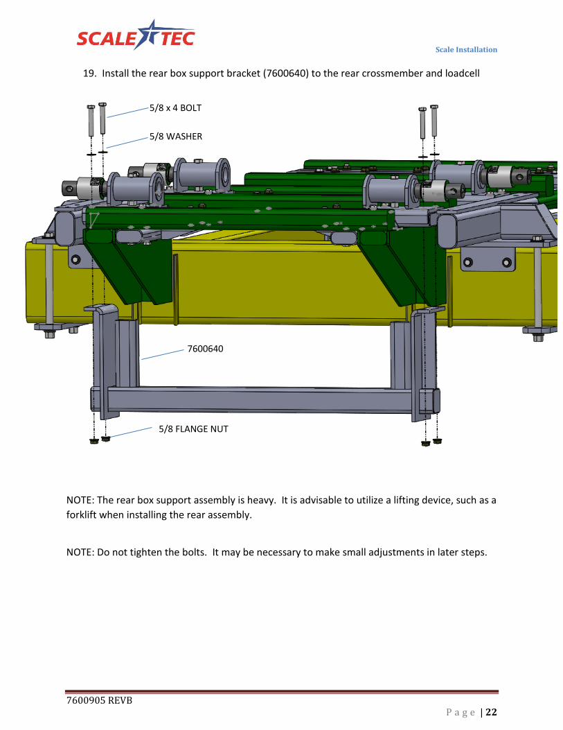
19. Install the rear box support bracket (7600640) to the rear crossmember and loadcell
assemblies. Use the 5/8” hardware depicted in the figure below.
NOTE: The rear box support assembly is heavy. It is advisable to utilize a lifting device, such as a
forklift when installing the rear assembly.
NOTE: Do not tighten the bolts. It may be necessary to make small adjustments in later steps.
5/8 x 4 BOLT
5/8 WASHER
7600640
5/8 FLANGE NUT

Scale Installation
7600905 REVB P a g e | 23
5/8 x 7 ½ BOLT 5/8 x 7 BOLT
5/8 WASHER
5/8 FLANGE NUT
20. Install the left and right mid rear load cell retaining brackets (7600910) to the front top
of the left and right axle brackets. Do not tighten the hardware on these bracket, this
will be done in a later step.
21. Install the left and right rear load cell retaining brackets (7600910) to the rear top of the
left and right axle brackets. Do not tighten the hardware on these brackets, this will be
done in a later step.
5/8 x 7 BOLT
5/8 WASHER
5/8 FLANGE NUT

Scale Installation
7600905 REVB P a g e | 24
NOTE: The proper gap should be 1/4” on both sides of the spreader box. When the scale
system is properly installed, it will move the spreader box to the rear 1 to 2 inches and lift it 2
inches.
Tightening Hardware
IMPORTANT:
It is very important that the procedure be followed for tightening the hardware on the scale system.
Failure to follow this method of tightening hardware can result in inaccurate weights due to binding of
the scale system.
1. Check chassis alignment and spreader box frame alignment. Ensure that the Spreader Box is
square and aligned to the chassis.
2. Ensure that the spreader box rear mounts are not binding and are free floating between the
mounting points. You will need to periodically check the spreader box rear mounts during the
tightening procedure to ensure that the spreader box does not bind.

Scale Installation
7600905 REVB P a g e | 25
3. Slide both rear axle brackets as far forward as possible and tighten the four metric bolts on the
rear side of the axle.
NOTE: After tightening the bolts on the left and right axles, do a quick check of allignment to
ensure the chassis and spreaderbox are still aligned, and it is not binding on the rear spreader
box mounts.
4. Tighten the 1” x 14” bolts that strap the rear axle brackets to the chassis. Do this for
both the left and right axles. NOTE: It is best to tighten the forward 1” x 14” bolt first.
5. Tighten the ¾” x 2” bolts on the front side of the axle brackets, securing the axle bracket
to the chassis. See figure below for a better discription of location.

Scale Installation
7600905 REVB P a g e | 26
6. Check the chasis and spreader box for alignment and ensure the rear spreader box
mounts are not binding on the axle
7. Tighten the middle couplers adjoining the rear assembly with the front assembly.
NOTE: Ensure the outside edge of the 2 x 4 tubing on the rail mounting brackets are
flush with the inside edge of the spreader box rails. See Figure Below.
8. Slide the rear outside loadcell mounts inward to its maximum limit and tighten the two
bolts that retain it to the axle brackets. Do this for all four outside loadcell mounts.
Refer to the figure below.
Scale Installation
7600905 REVB P a g e | 27
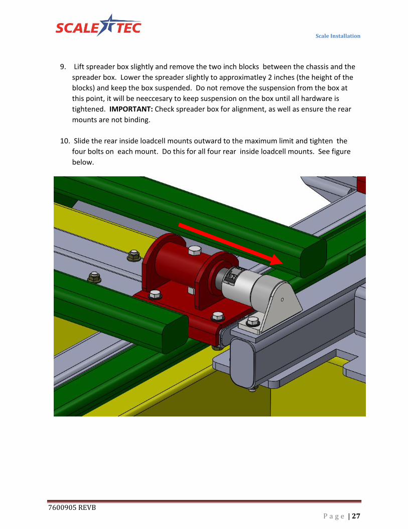
9. Lift spreader box slightly and remove the two inch blocks between the chassis and the
spreader box. Lower the spreader slightly to approximatley 2 inches (the height of the
blocks) and keep the box suspended. Do not remove the suspension from the box at
this point, it will be neeccesary to keep suspension on the box until all hardware is
tightened. IMPORTANT: Check spreader box for alignment, as well as ensure the rear
mounts are not binding.
10. Slide the rear inside loadcell mounts outward to the maximum limit and tighten the
four bolts on each mount. Do this for all four rear inside loadcell mounts. See figure
below.
Scale Installation
7600905 REVB P a g e | 28
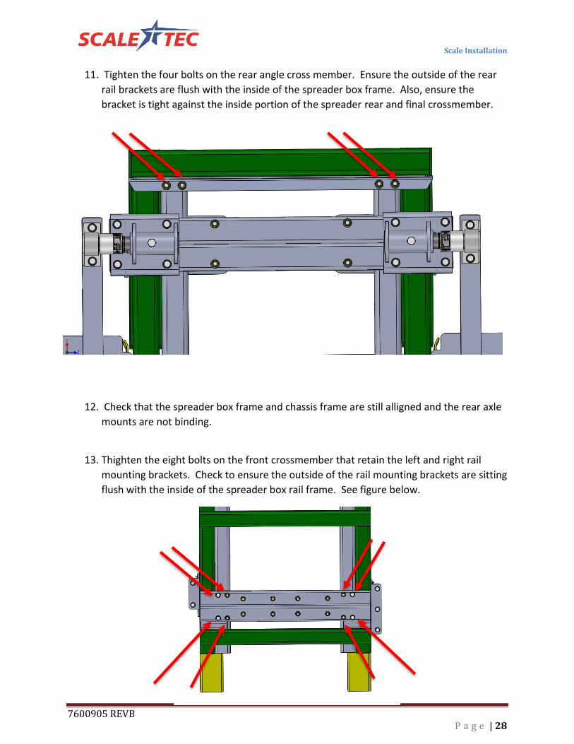
11. Tighten the four bolts on the rear angle cross member. Ensure the outside of the rear
rail brackets are flush with the inside of the spreader box frame. Also, ensure the
bracket is tight against the inside portion of the spreader rear and final crossmember.
12. Check that the spreader box frame and chassis frame are still alligned and the rear axle
mounts are not binding.
13. Thighten the eight bolts on the front crossmember that retain the left and right rail
mounting brackets. Check to ensure the outside of the rail mounting brackets are sitting
flush with the inside of the spreader box rail frame. See figure below.

Scale Installation
7600905 REVB P a g e | 29
14. Tighten the inner bolts (eight total) securing the rear crossmembers to the rearl rail
mounts. See figure below.
IMPORTANT: Prior to proceeding with tightening ensure the following…
1. The outside edge of the forward and rear rail mounts are sitting flush against the
inside eged of the spreader box frame.
2. The rear spreader mounts located on the rear side of the axle have approximatley
1/4 inch clearance allowing the spreader to “float” inbetween the gussets.
Scale Installation
7600905 REVB P a g e | 30
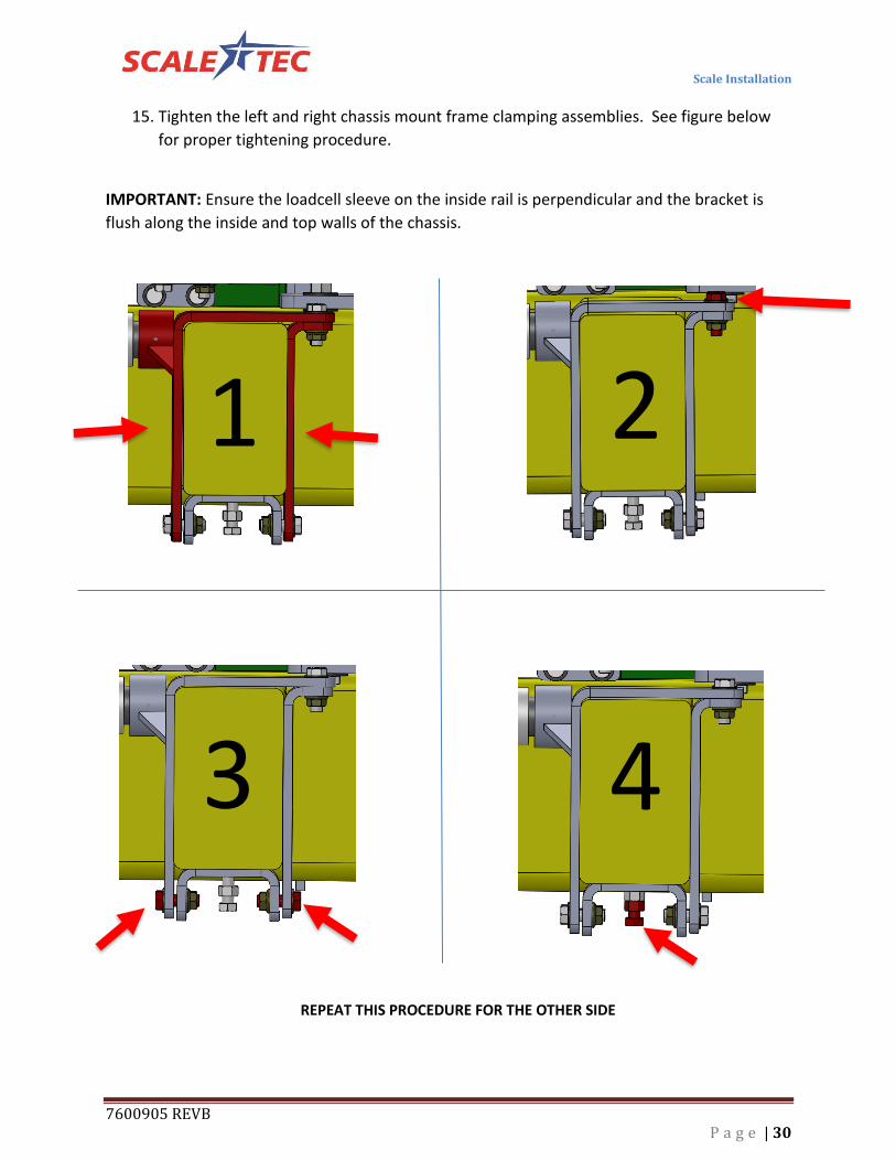
15. Tighten the left and right chassis mount frame clamping assemblies. See figure below
for proper tightening procedure.
IMPORTANT: Ensure the loadcell sleeve on the inside rail is perpendicular and the bracket is
flush along the inside and top walls of the chassis.
1 2
3 4
REPEAT THIS PROCEDURE FOR THE OTHER SIDE

Scale Installation
7600905 REVB P a g e | 31
16. Slide the front top loadcell mounts toward the outside of the spreader chassis to its
maximum limit and tighten the eight bolts that secure the top loadcell mounting bracket
to the front crossmember.
z
17. After tightening procedure is complete. Re-Install the backup alarm to the right side
axle bracket. There is a plate located on top of the axle bracket that allows for securing
the backup alarm to the chassis. Use the original hardware to secure the backup alarm
to the axle bracket.
Greese Application
1. After the mounting is complete it will be necessary to greese all fittings on the scale
system. Each loadcell needs to be greesed prior to first use. Greese fittings until you
can visably see greese protruding from the sleeve of the loadcell. Refer to the
maintenance section for proper maintenance intervals of grease application.
IMPORTANT: Ensure the loadcell is perpendicular and
at a right angle to the frame of the chassis. Failure to
maintain this perpendicular profile will result in
inaccurate weights.
FINAL CHECK: Ensure alignment on the frame and that the rear spreader box mounts are
allowing the spreader to “Float” within the mounting flanges on the rear of the axle.

Junction Box Installation
7600905 REVB P a g e | 32
JUNCTION BANK MOUNTING
DT06 Junction Bank
The junction bank is water resistant, not water-proof. It should be mounted to avoid submersion during
wet weather and to avoid physical abuse. The junction bank can be mounted on the front or rear of the
drill, planter or seeder. All load cell cables must reach the junction bank. Install by removing the double
sided VHB tape backing and apply to a cleaned surface.
Connect Load Cell and Junction Box Cable
1. Route front and rear load cell cables to Junction Bank
location. Make sure they are not bound or pinched. Cable
tie (Customer provided) load cell cables in place.
2. Insert the load cell cables DT06 connector J-box cables
into each available port of the Junction Bank.
NOTE: There are six available ports for loadcells with a
seventh position utilized for the interface cable to the
indicator or scale controller device.
3. Ensure any remaining unused ports on the junction box
are filled with the plugs provided within the kit.
NOTE: Best practice is to install the junction bank onto a surface
so it is secured in a vertical position perpendicular to the surface
of the ground. See illustration to the right. Although the
connection system is rated to prevent moisture and dust
intrusion, it is still advisable to not install the junction bank with
the connectors facing the upward to the sky.

Indicator Mounting
7600905 REVB P a g e | 33
INDICATOR MOUNTING
RAM MOUNT The scale indicator can be mounted in the tractor cab or on the drill with swivel mounting pack
(406081). Two cables must be connected to the indicator bottom panel, J-Box and power cables.
Refer to Indicator Manual D3831-US for details of indicator mounting options and connection of
power cord.
INDICATOR MOUNTINGS
PLANTER MOUNTING TRACTOR CAB MOUNTING
1. Bolt the readout in the cab with the bracket, or mount the bracket in the front of the lift
cylinder.
2. Install power cord to a 12-volt negative ground battery.
3. Route J-box cable to indicator and install to indicator bottom panel.
Power Connection:
The power cable should be connected directly to a vehicle battery or regulated power supply. The scale
end of the power cable is attached to the J901 connector located on the bottom panel of the indicator.
Connect the RED wire from the power cable to +12 VDC and the BLACK wire to GROUND. The indicator is
fused internally at 4 amps.
Power Cable Connections:
Wire Color Wire Function
Red Battery (+12 VDC)
Black GROUND

Testing and Trouble Shooting
7600905 REVB P a g e | 34
TESTING AND TROUBLE SHOOTING
IMPROTANT All bars need to weigh accurately before it will be beneficial to recalibrate your
indicator
Inaccurate weights? 1) Measure the same person, or a 200 pound weight, on each of the weigh bars.
• If one weighs negative, turn that weigh bar over. (An upside down bar will weigh negative.)
• If one side is weighing 20% light, check for an obstruction. Is anything binding or any metal
rubbing?
• Could be a faulty weigh bar
• If they are all even weights, but are weighing light or heavy, you need to adjust the calibration.
If your scale is more than 5% off, call us for help, as your scale may have had the wrong
calibration number put in it from the factory. 1-888-962-2344.
• The hopper being weighed needs to be at least ¾ full for us to adjust calibration.
• Check operator’s manual or give us a call at 1-888-962-2344.
Erratic weights? The following process needs to occur in an effort to eliminate one part at a time in an effort to find the
problem! When you reconnect the faulty part you will have erratic readings again.
1) Disconnect the junction box cord from the indicator marked “load cells”. The indicator should
stabilize after 45 seconds. Try to zero out the indicator. IF the indicator won’t zero out, the indicator is
the problem.
IF it will zero out:
2) Connect the junction box back to the indicator. And then disconnect all of the load cells from the
junction box.
3) Zero out the indicator. IF the indicator won’t zero out the problem is the junction box or the junction
box cable.
IF it will zero out:
4) Reconnect the load cells ONE AT A TIME, zeroing out the indicator each time. When you reconnect
the faulty load cell, you will have erratic readings again.

Operating the Scale
7600905 REVB P a g e | 35
OPERATING THE SCALE
Filling the Spreader 1. Push the "Start" button. The screen will show zero, and the arrow is now pointing to "Net" on the
screen. This is a temporary zero point to start loading the hopper with seed.
2. Fill product into the fertilizer spreader hopper.
3. Note the weight of product filled into the spreader.
4. Push the “Stop” button, the weight will return to the Net inventory in the hopper.
5. If filling a second bin in the fertilizer hopper, push the "Start button again. The screen will say zero
again.
6. Fill the second hopper on the fertilizer spreader.
7. Note the weight of the product you filled into the second hopper.
4. Push "Stop" and the screen will now return to the Net inventory on the spreader (both products
weighed together as one single weight).
Monitoring your application rate
NOTE: This procedure assumes all hoppers have been filled to some degree and you are ready to apply.
1. Prior spreading stop the implement in relatively level location.
3. Let the scale stabilize, after stabilization, press the "start" button.
4. Start spreading.
5. Spread a 3-5 acre area.
6. Stop the spreader in a relatively level position.
7. Let the scale stabilize, after stabilization note the weight displayed on the indicator. The weight
displayed is the weight that was applied over the 3-5 acre area.
8. Adjust your dry rate controller as necessary.

Repair Parts
7600905 REVB P a g e | 36
REPAIR PARTS FRONT HALF OF SCALE ASSEMBLY
Refer to page 39 for part number key.
Repair Parts
7600905 REVB P a g e | 37
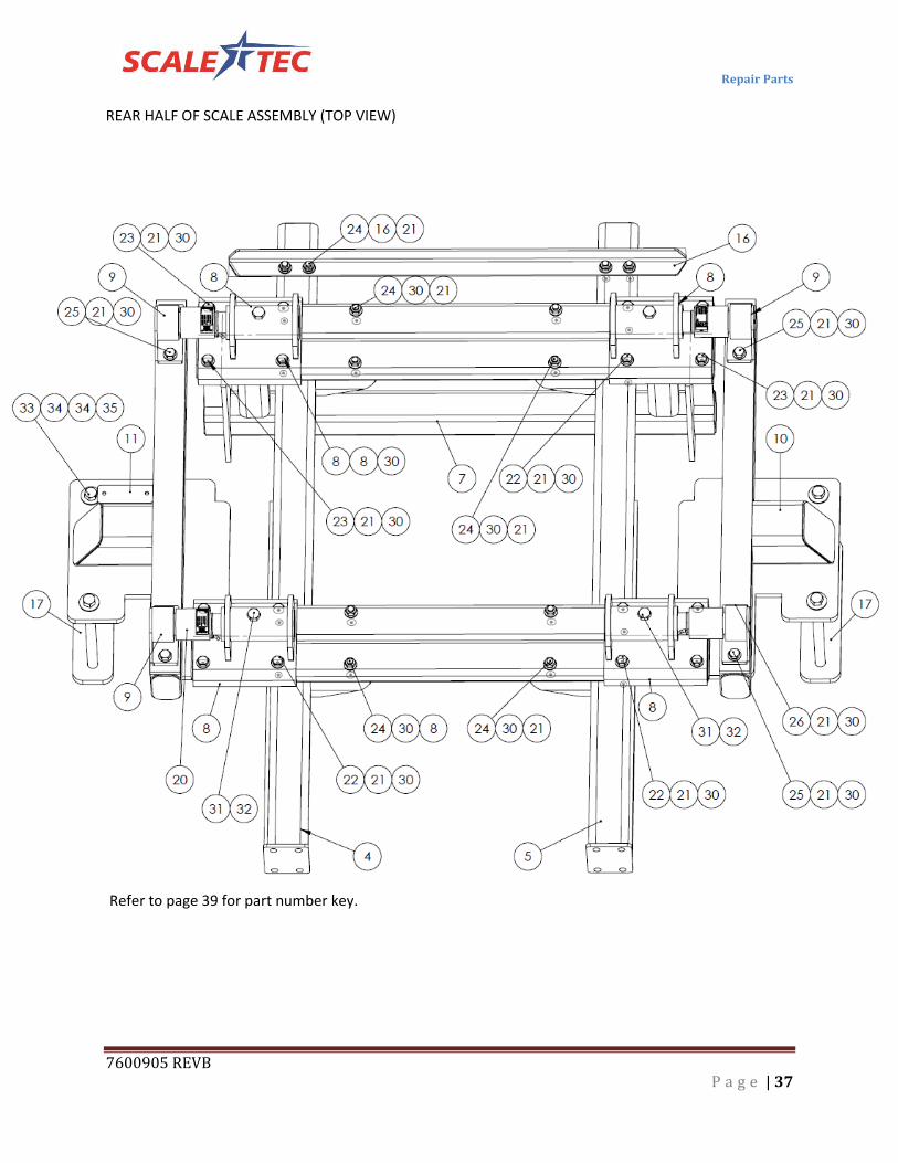
REAR HALF OF SCALE ASSEMBLY (TOP VIEW)
Refer to page 39 for part number key.

Repair Parts
7600905 REVB P a g e | 38
REAR HALF OF SCALE ASSEMBLY (BOTTOM VIEW)
Refer to page 39 for part number key
R4038 Kit Only Part Number Description Quantity
7601611 Weld - Spacer Tube Left Front 4038 1
7601612 Weld - Spacer Tube Right Front 4038 1
7601613 Part - Bushing 2.5" Long 4038 4
7601225 Bolt 5/8 x 4 Grade 8 4
7601528 Bolt 16mm x 100mm Grade 10.9 4
7601210 Bolt 1 x 12 Grade 8 4

Repair Parts
7600905 REVB P a g e | 39
PART NUMBER KEY (REFER TO DRAWINGS ON PREVIOUS PAGES FOR PART LOCATIONS)
ITEM NO. Part Number DESCRIPTION QTY.
1 7600654 Weld - Front CM w/ 2x2 Spacer R4045 1
2 7600633 Weld - Front Base Bracket LC R4045 2
3 7600656 Weld - Right & Left Front Frame Support R4045 2
4 7600647 Weld - Right Rear Frame Support R4045 1
5 7600650 Weld - Left Rear Frame Support R4045 1
6 7600645 Weld - Rear Cross Member R4045 2
7 7600640 Weld - Rear Support Beam R4045 1
8 7600652 Weld - Rear LC Base Bracket R4045 4
9 7600910 WELD- LC RECEIVER MOUNT 4
10 7600642 Weld - Left Axle Bracket R4045 1
11 7600644 Weld - Right Axle Bracket R4045 1
12 7600904 Weld - Front Right Side Bracket R4045 1
13 7600908 Weld - Front Left Side Bracket R4045 1
14 7600685 CHANNEL- CLAMP LEFT FRNT 4045 1
15 9100418 Part - Front Left Outside Clamping Plate R4045 1
16 7600660 Part - Rear Angle Cross Support R4045 1
17 7600670 STRAP- AXLE 4045 2
18 9100413 Weld - Front Right Side Bracket R4045 1
19 7600686 CHANNEL- CLAMP FRNT RIGHT 4045 1
20 400061 LOADCELL 6
21 7600569 WASH-5/8 FLAT G8 79
22 STB5-8X51-4G8 BOLT 5/8 x 5 1/4 G8 8
23 STB5-8X4G8 BOLT 5/8 x 4 G8 4
24 STB5-8X31-4G8 BOLT 5/8 x 3 1/4 G8 24
25 STB5-8X7G8 BOLT 5/8 X 7 G8 6
26 STB5-8X71-2G8 BOLT 5/8 X 7 1/2 G8 2
27 STB5-8X11-2G8 BOLT 5/8 X 1 1/2 G8 8
28 STB5-8X5G8 BOLT 5/8 X 5 G8 8
29 STB5-8X2G8 BOLT 5/8 X 2 G8 19
30 STFN5-8 SER FLANGE NUT 5/8 G8 75
31 STB3-4X4G8 BOLT 3/4 X 4 G8 6
32 STLN3-4G8 LOCK NUT 3/4 G8 10
33 STB1X14G8 BOLT 1 x 14 G8 4
34 7600801 WASH-1 FLAT G8 8
35 7600770 NUT 1" G8 4
36 7600712 BOLT- M16 X 90 mm G10 4
37 7600675 SPACER-AXLE MOUNT 4045 4
38 STB3-4X2G8 BOLT 3/4 X 2 G8 4
39 STW3-4 WASH-3/4 8
42 7600563 LOCK NUT- 5/8 4
43 7600772 WASHER- SPLIT LOCK 1" 4

Repair Parts
7600905 REVB P a g e | 40
406081
406385
406081
KEY QTY. PART NO. DESCRIPTION
1 1 403980 Brkt – Robo Mtg
2 2 406086 Brkt – Swivel Cast (JD H161618)
3 2 406087 Gasket – 1.813OD x 1.218 ID x .313 WID
4 2 400036 Scr – 1/4-20 x 3/4 HHCS ZP
5 2 400038 Washer – Lock 1/4 ZP
6 2 400035 Nut – 1/4-20 ZP
7 2 405989 Scr – 3/8-16 x 3.0 HHCS ZP Grd 5
8 2 404292 Nut – 3/8-16 Nyloc ZP
9 2 405612 GT400 Indicator (Not included in kit 406081)
406385
KEY QTY. PART NO. DESCRIPTION
1 1 404230 Ram Suction Cup with Twist Lock
2 2 403180 Assembly – 1” Ram Mount
3 2 403779 Scr - #10 x 5/8 PHSTS 48-2 Blk ZP

MAINTENANCE REQUIREMENTS
7600905 REVB P a g e | 41
Maintenance Requirements
25 hour Maintenance
Grease the 6 fittings on the spreader every 25 hours. Failure to grease fittings could result in inaccurate
weights and may cause the load cells to seize and bind.
100 hour Maintenance
Check all hardware is tight.
Ensure the hardware on the axles (1” x 14” bolts) are tight and ensure they are torqued to 600 ft. Lbs
Check hardware for excessive corrosion and replace hardware as needed.