john h. underwood and g. peter o' · pdf filethermal gradient, thermal stress,...
TRANSCRIPT

"* AD-A266 347
DTIC 1,AD
EN 2, -C993 TECHNICAL REPORT ARCCB-TR-93017
A
THERMAL GRADIENT-INDUCED DEFLECTIONOF A THICK-WALLED CYLINDER WITH
BENDING RESIDUAL STRESSES
JOHN H. UNDERWOOD AND G. PETER O'HARA
APRIL 1993
US ARMY ARMAMENT RESEARCH,DEVELOPMENT AND ENGINEERING CENTER
CLOSE COMBAT ARMAMENTS CENTERBEN9T LABORATORIES
WATERVLIET, N.Y. 12189-4050
APPROVED FOR PUBLIC RELEASE; DISTRIBUTION UNLIMITED
""93 93-14660

DISCLA14ER
The findings in this report are not to be construed as an official
Department of the Army position unless so designated by other authorized
documents.
The use of trade name(s) and/or manufacturer(s) does not constitute
an official indorsement or approval.
DESTRUCTION NMCOT
For classified documents, follow the procedures in DoD 5200.22-M,
Industrial Security Manual, Section 11-19 or DoD 5200.1-R, Information
Security Program Regulation, Chapter IX.
For unclassified, limited documents, destroy by any method that will
prevent disclosure of contents or reconstruction of the document.
For unclassified, unlimited documents, destroy when the report is
no longer needed. Do not return it to the originator.

"I Form Approved
REPORT DOCUMENTATION PAGE QM, No 0704-O088
eubhc( reuOO f u Cn for tja pct COI ontfl 0o ,ritofnamtiofl • eitu"te to avterage • mOt r o ' ewor'•e ,•cýuA g t timle Oe ,efe.n. g sjruc o"I .e r., ;..J r-qathe nq An Ci. ml~dfll,'q Ch• •ata nEEde. JndeO(nolOettl/q And rC.~ew~rnq zt~e0J;lertnon t .ttOrmtO; 5erno om..enr~t• r ean.• r'.nO,~Qen C-s','.re ,•. -- m.• •,0e': 21? T•
O&$ jMghwryu, Suite •204. ArtinttOrn. 4A 2202-3402. and to ine Otf1ieef Managem"i .amswue•i . Psoerwctx RC•e mon Proj oi-ct i• 8 ,n Tn .( ,C
1. AGENCY USE ONLY (Leave blank) 2. REPORT DATE 37 REPORT TYPE AND DATES COVERED
I April 1993 Final]
4. TITLE AND SUBTITLE 5. FUNDING NUMBERSTHERMAL GRADIENT-INDUCED DEFLECTION OF ATHICK-WALLED CYLINDER WITH BENDING AMCMS: 616224H19011RESIDUAL STRESSES PRON: A117ZICBNMBJ
6. AUTHOR(S)
John H. Underwood and G. Peter O'Hara
7. PERFORMING ORGANIZATION NAME(S) AND AOORESS(ES) 8. PERFORMING ORGANIZATION
U.S. Army ARDEC REPORT NUMBER
Benet Laboratories. SMCAR-CCB-TL ARCCB-TR-93017Watervliet. NY 12189-4050
9. SPONSORING/MONITORING AGENCY NAME(S) AND AODRESS(ES) 10. SPONSORING MONITORINGAGENCY REPORT NUMBER
U.S. Army ARDECClose Cowbat Armamenis CenterPicatinny Arsenal. NJ 07806-5000
11. SUPPLEMENTARY NOTESPresented at the ASME Pressure Vessels and Piping Conference, New Orleans. LA. 21-25 June 1992. Published in theProceedings of the Conference.
12a. DISTRIBUTION /AVAILABILITY STATEMENT 12b. DISTRIBUTION CODE
Approved for public release; distribution unlimited
13. ABSTRACT (Maxsmum 200 words)The interaction of a thermal gradient with bending residual stresses in a thick-walled cylinder is investigated using erpermentaimeasurements from prior work. mechanics analysis, and finite element stress analysis. A temperature gradient is applied to acylinder containing residual stresses due to plastic bending resulting in transient elastic relaxation of the nonaxisvmmetncresidual stresses and bending of the cylinder. Analysis of the well-known similar problem in a rectangular bar is done first usingsolid mechanics solutions of ideal cases. Finite element calculations are made of the residual stresses following plastic bendingof a thick-walled cylinder, the effects of a temperature distribution, and the resultant changes in stresses and strains and theassociated tube bending. Results from the two approaches for a 200"C temperature gradient show a maximum angulardisplacement of 0.004 to 0.008 deg/m and the displacement returning to zero as the thermal gradient diminishes with tune.
14. SUBJECT TERMS 15. NUMBER OF PAGES
Thermal Gradient, Thermal Stress, Thick-Walled Cylinder. Residual Stress. 15'Finite Element Analysis 16. PRICE CODE
17. SECURITY CLASSIFICATION 18, SECURITY CLASSIFICATION 19. SECURITY CLASSIFICATION 20. LIMITATION OF ABSTRACTOF REPORT OF THIS PAGE Or A81TRACT
UNCLAFSSFIL6 UNCLASSIFIED UNCLASSIFIED UL
NSN 7540-01-280-5500 Standaro :-Orr .98 Rev 2.891'2S(. O' O AZ S
TABLE OF CONTENTS
ACKNOW LEDGEM ENTS ......................................................... ii
INTROD UCTION ........................................................
A N A L Y SIS ..................................................................... I
Temperature Effects on Modulus ............................................... I
Rectangular Bar Analysis ..................................................... I
Cylinder Finite Element Analysis .............................................. 2
R E SU L T S ...................................................................... 3
B ar R esults ............................................................... 3
Cylinder R esults ........................................................... 4
SUMMARY AND CONCLUSIONS ........................................... ...... 5
REFERENCES ................................................................. 6
Tables
1. Rectangular Bar Temperature Distribution Results ................................... 4
2. Cylinder Bending and Residual Stress Results ........................................ 5
List of Illustrations
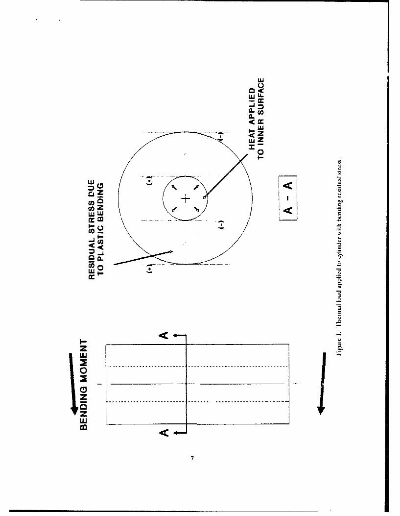
1. Thermal load applied to cylinder with bending residual stress ............................. 7
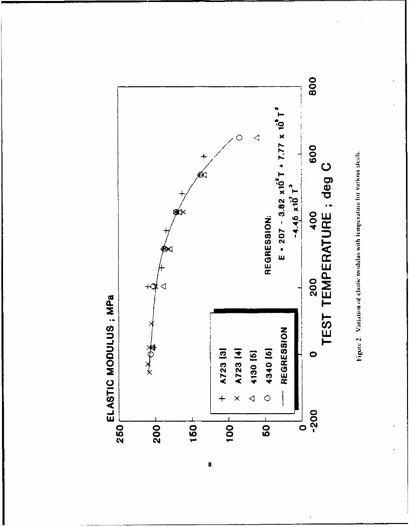
2. Variation of elastic modulus with temperature for various steels ........................... 8
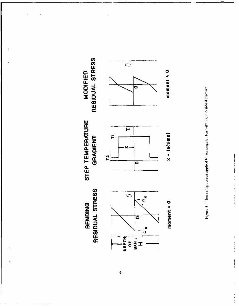
3. Thermal gradient applied to rectangular bar with ideal residual stresses ...................... 9
4. Residual stress and temperature distributions for cylinder and bar ......................... 10
5. Change in angular displacement for bar due to moving step thermal gradient ................. 11
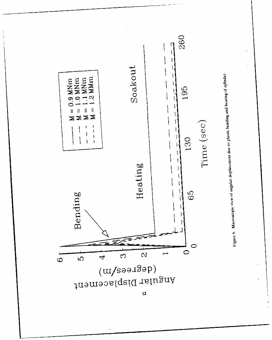
6. Macroscopic view of angular displacement due to plastic bending and heating of cylinder ........ 12
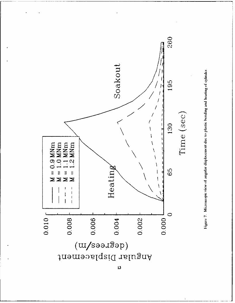
7. Microscopic view of angular displacement due to plastic bending and heating of cylinder ........ 13
ACcesio' FI-or
V~1T! q¶z.~ jA>SNTIS CRA&~.I"• ~~DTic i ,,,
J •J;,ti C iI~ i,;
By
D, Jt t
A-
ACKNOWLEDGEMENTS
We are pleased to acknowledge R. Farrara, V. Olmstead, and B. Avitzur of Benet Laboratoriesfor helpful discussions during this work.
ii
INTRODUCTION
The dimensional stability of a thick-walled cylinder containing residual stresses is of concern,because thick-wailed cylinders with significant overstrain stresses are often subjected to high pressures andelevated temperatures. Throop and coworkers (ref 1) measured the permanent closing of the inner radiusof overstrained cylinders when subjected to elevated temperatures and varying amounts of temperaturegradient. This prior work had general application to cannon and to other uses of cylinders that requiredimensional stability.
The topic here is more specialized. It addresses the transient interaction of a thermal gradientwith bending residual stresses in a thick-walled cylinder. The problem is sketched in Figure 1. If thecylinder were first bent beyond the plastic limit, a residual stress distribution of the type shown by thedashed lines could be produced. In general, tensile residual stress is present at locations that experiencedcompressive yielding during prior bending, and compressive residual stress is present at locations thatexperienced prior tensile yielding. Note that the residual stress distribution is not axisymmetric; ofparticular note, the stresses at opposite points of the inner surface are of the opposite sense. Then, whenheat is applied to the inner surface, a transient elastic relaxation--due to reduced elastic modulus atelevated temperature--of the nonaxisymmetric residual stresses will cause bending of the cylinder. Theamount of bending may be small, but for cannon applications, even a small amount of angulardisplacement of the cylinder can cause a significant deviation in the projectile position after it has traveleda large distance. The bending of the cylinder will be particularly bothersome, because it will appear andthen disappear as the thermal gradient forms and then diminishes. This problem of the transient angulardisplacement of a previously bent cylinder subjected to thermal gradient is studied in the followingparagraphs.
ANALYSIS
Temperature Effects on Modulus
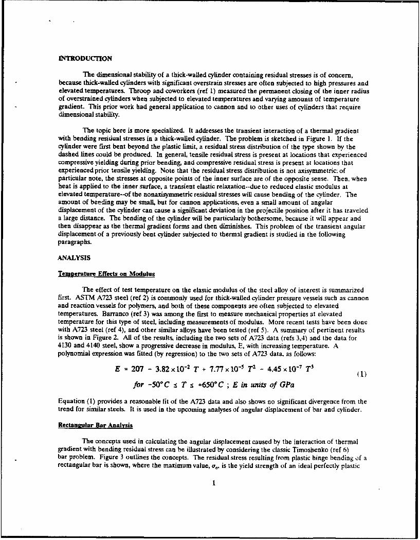
The effect of test temperature on the elastic modulus of the steel alloy of interest is summarizedfirst. ASTM A723 steel (ref 2) is commonly used for thick-walled cylinder pressure vessels such as cannonand reaction vessels for polymers, and both of these components are often subjected to elevatedtemperatures. Barranco (ref 3) was among the first to measure mechanical properties at elevatedtemperature for this type of steel, including measurements of modulus. More recent tests have been donewith A723 steel (ref 4), and other similar alloys have been tested (ref 5). A summary of pertinent resultsis shown in Figure 2. All of the results, including the two sets of A723 data (refs 3,4) and the data for4130 and 4140 steel, show a progressive decrease in modulus, E, with increasing temperature. Apolynomial expression was fitted (by regression) to the two sets of A723 data, as follows:
E = 207 - 3.82 x 10⁻² T + 7.77 x 1O5 T2 - 4,45 X 10⁻⁷ T3(1)
for -50° C T s +650 0C ; E in units of GPa
Equation (1) provides a reasonable fit of the A723 data and also shows no significant divergence from thetrend for similar steels. It is used in the upcoming analyses of angular displacement of bar and cylinder.
Rectanaular Bar Analysis
The concepts used in calculating the angular displacement caused by the interaction of thermalgradient with bending residual stress can be illustrated by considering the classic Timoshenko (ref 6)bar problem. Figure 3 outlines the concepts. The residual stress resulting from plastic hinge bending of arectangular bar is shown, where the maximum value, a0 , is the yield strength of an ideal perfectly plastic

material. If a step temperature gradient is envisioned to proceed outward from the neutral axis of thebeam, that is, x proceeds from 0 to RI-2, then a modified residual stress distribution results. The keypoints are that the reduced elastic modulus at elevated temperatures causes the modified stress, and thatthe modified stress results in an unbalanced moment and an associated angular displacement of the bar.
Equations of solid mechanics describing these concepts were developed by writing expressions forthe bending moment due to the bending residual stress distribution shown in Figure 3, following thegeneral procedure of Timoshenko (ref 6). One expression, Eq. (2), describes the moments (designated aspositive) from the bar neutral axis outward to the points where ihe residual stress is zero at x/H = ± 1/3.
.Equation (3) is for the remaining moments. The nondimensional expressions for moment, M, as afunction of relative position in the bar, x/H, are
M/o0 bH2 = [x/HJ3[1 + (1 - 3xH)/(x/1DJ (2)for 0 * +x/H s 1/3
M/c00bH 2 = [1/27 - (xH- 1/3) 2(2x/H + 1/3)] (3)for 1/3 s tx/H -• 1/2
Note that both Eq. (2) and (3) reduce to Timoshenko's result, that is, M/a7bH2 = 1/27 for ± x/H = 13.
The second expression required for calculation of the thermal gradient-induced angulardisplacement of the bar is for the angular displacement as a function of the moment as modified by thegradient. This is obtained from the known relationship between moment and angle, 0, (in degrees) for abeam (ref 7)
0 = 180 MyI/EI (4)
where y is the length of beam over which the moment is applied, and I is the moment of inertia (bH 3'12).The total moment, M, is multiplied by a factor (AE/E) to define the modified moment due only to thechange in modulus with temperature
M' = (A E/EM (5)
Values of (AE/E) are easily obtained from Eq. (1). Then, the calculated angular displacement dueto the thermal gradient-induced change in modulus is
0 = 180(AEIE)MyIirEI (6)
Equations (2), (3), and (6) were used to calculate the angular displacement of a rectangular barwith similar configuration, residual stress, and temperature conditions as those used for thick-walledcylinder finite element calculations. A comparison of the two sets of results was made as an aid tounderstanding the nature of the effects and as a consistency check on the results.
Cylinder Finite Element Analysis
The finite elcment analysis modeled a thick-walled cylinder subjected to a complex history ofbending and heating. The cylinder was 1.0 m long, had an inner diameter (ID) of 0.1 m, an outerdiameter (OD) of 0.2 m, and the elastic modulus properties discussed in relation to Figure 2. The loadand heating history included a constant applied bending moment that resulted in significant plastic
2

deformation and residual stress, relaxation to zero load, heating at the ID to produce a significant thermalgradient, and soak-out to a uniform elevated temperature. Changes in curvature of the 1.0-m longsegment were monitored by observing the total angular displacement of the ends of the cylinder.
The heating problem was solved first using ABAQUS two-dimensional diffusion elements(DC2D8) in a mesh defining 192 elements on a symmetric half of the cross section of the cylinder.Heating on the ID from a hot gas was simulated using a film heat transfer coefficient of 500 J/mzs and agas temperature of 1000°C. The heat was applied for 120 seconds resulting in an ID temperature of 336°Cand an OD temperature of 138*C. The heating was then stopped, and the cylinder was allowed to soak-out to a nearly uniform temperature of 187*C. The thermal solutfon was checked to ensure that thetemperature distribution was symmetric about the cylinder axis and stored for use in the full structuralproblem. Structural analysis was performed using the same mesh as the thermal analysis, with thesubstitution of ABAQUS eight-node generalized plane-strain elements (CGEP10). This element type usestwo global nodes to model the three degrees of freedom at the ends of the prism defined by the crosssection mesh. One node defines the change of length of the prism, and the other node defines the tworotations at the end planes. In this study, the beam length was left free of constraint, one rotation wasconstrained to enforce the symmetry condition, and the second rotation was used to apply a constantbending moment in the bending phase of the analysis. This is also the degree of freedom that is plotted asangular displacement in the final results.
The full bending and heating analysis started with the cylinder at 20OC and proceeded in four
steps:
1. a 10-second loading sufficient to produce plastic deformation:
2. a 10-second unloading to produce the appropriate nonsymmetric residual stress state:
3. a 120-second heating using temperature information from the thermal solution:
4. a 120-second soak-out using temperatures from the thermal solution.
This produced a total time for the full analysis of 260 seconds, which can be used as a basis for plottingthe angular displacement of the ends of the cylinder. The level of the final residual stress was controlledby the maximum applied bending moment that was varied in five steps from 0.4 to 0.6 MNm. Thesolution at 0.4 MNm was completely elastic. The remaining four solutions are shown as plots of angulardisplacement versus time in the upcoming results.
RESULTS
Bar Results
Example temperature and residual stress distributions from the cylinder analysis and thecorresponding stress and temperature input values for the bar analysis are shown in Figure 4. Thecylinder results are for a prior bending moment of 1.2 MNm and for the temperatures at the point 140seconds into the 260-second long bending and heating cycle. The temperature difference between ID andOD at this point was a AT of 1989C. For comparison, AT values of 90°C to 2300 C (depending on forcedair or water cooling on the OD) were measured in tests of A723 cylinders (ref 1). Note that the value ofresidual stress at the ID of the cylinder, -230 MPa, is much below the yield stress of the A723 steel used inthe cylinder model, I i22 MPa. The value of -230 MPa was used in the bar analysis, along with the two-step thermal gradients shown as dashed lines--one based on the average temperature over the inner two-thirds of the wall from the cylinder analysis (240°C), and the other based on the ID temperature from thecylinder analysis (336°C).
3
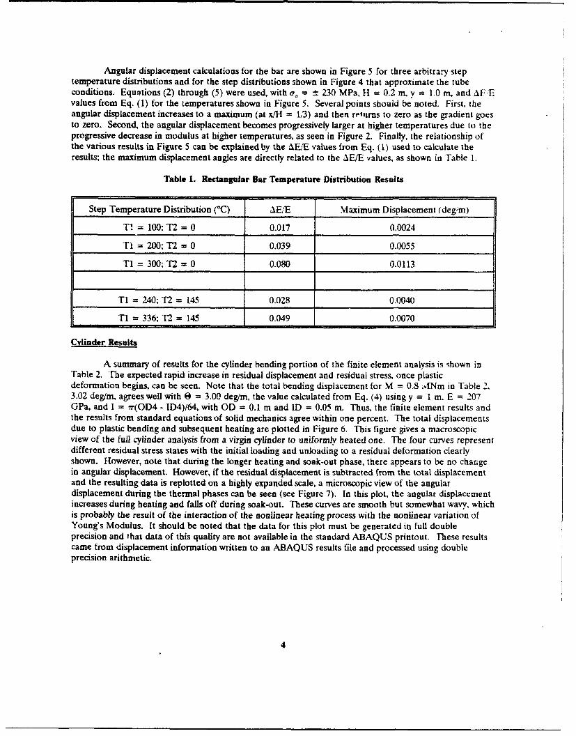
Angular displacement calculations for the bar are shown in Figure 5 for three arbitrary steptemperature distributions and for the step distributions shown in Figure 4 that approximate the tubeconditions. Equations (2) through (5) were used, with ao = 230 MPa, H = 0.2 n, y = 1.0 m, and AFEvalues from Eq. (1) for the temperatures shown in Figure 5. Several points should be noted. First, theangular displacement increases to a maximum (at x/H = 1,3) and then returns to zero as the gradient goesto zero. Second, the angular displacement becomes progressively larger at higher temperatures due to theprogressive decrease in modulus at higher temperatures, as seen in Figure 2. Finally, the relationship ofthe various results in Figure 5 can be explained by the &E/E values from Eq. (1) used to calculate theresults; the maximum displacement angles are directly related to the AE/E values, as shown in Table 1.
Table 1. Rectangular Bar Temperature Distribution Results
Step Temperature Distribution (°C) IE/E Maximum Displacement (degm)
T! = 100; T2 = 0 0.017 0.0024
Ti = 200; T2 = 0 0.039 0.0055
T1 = 300; T2 = 0 0.080 0.0113
T1 = 240; T2 = 145 0.028 0.0040
TI = 336; T2 = 145 0.049 0.0070
Cylinder Results
A summary of results for the cylinder bending portion of the finite element analysis is shown inTable 2. The expected rapid increase in residual displacement and residual stress, once plasticdeformation begins, can be seen. Note that the total bending displacement for M = 0.8 1dNm in Table 2,3.02 deg/m, agrees well with 0 = 3.00 deg/m, the value calculated from Eq. (4) using y = I m. E = 207GPa, and I = ir(OD4 - ID4)/64, with OD = 0.1 m and ID = 0.05 m. Thus, the finite element results andthe results from standard equations of solid mechanics agree within one percent. The total displacementsdue to plastic bending and subsequent heating are plotted in Figure 6. This figure gives a macroscopicview of the full cylinder analysis from a virgin cylinder to uniformly heated one. The four curves representdifferent residual stress states with the initial loading and unloading to a residual deformation clearlyshown. However, note that during the longer heating and soak-out phase, there appears to be no changein angular displacement. However, if the residual displacement is subtracted from the total displacementand the resulting data is replotted on a highly expanded scale, a microscopic view of the angulardisplacement during the thermal phases can be seen (see Figure 7). In this plot, the angular displacementincreases during heating and falls off during soak-out. These curves are smooth but somewhat wavy, whichis probably the result of the interaction of the nonlinear heating process with the nonlinear variation ofYoung's Modulus. It should be noted that the data for this plot must be generated in full doubleprecision and that data of this quality are not available in the standard ABAQUS printout. These resultscame from displacement information written to an ABAQUS results file and processed using doubleprecision arithmetic.
4
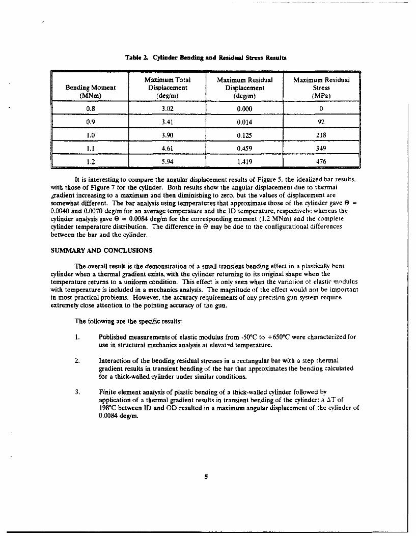
Table 2. Cylinder Bending and Residual Stress Results
Maximum Total Maximum Residual Maximum ResidualBending Moment Displacement Displacement Stress
(MNm) (degim) (deg/m) (MPa)
0.8 3.02 0.000 0
0.9 3.41 0.014 92
1.0 3.90 0.125 218
1.i 4.61 0.459 349
1.2 5.94 1.419 476
It is interesting to compare the angular displacement results of Figure 5, the idealized bar results,with those of Figure 7 for the cylinder. Both results show the angular displacement due to thermalgradient increasing to a maximum and then diminishing to zero, but the values of displacement aresomewhat different. The bar analysis using temperatures that approximate those of the cylinder gave 0 =0.0040 and 0.0070 deg/m for an average temperature and the ID temperature, respectively: whereas thecylinder analysis gave 0 = 0.0084 deg/m for the corresponding moment (1.2 MNm) and the completecylinder temperature distribution. The difference in 0 may be due to the configurational differencesbetween the bar and the cylinder.
SUMMARY AND CONCLUSIONS
The overall result is the demonstration of a small transient bending effect in a plastically bentcylinder when a thermal gradient exists, with the cylinder returning to its original shape when thetemperature returns to a uniform condition. This effect is only seen when the variation ot elastic moduluswith temperature is included in a mechanics analysis. The magnitude of the effect would not be importantin most practical problems. However, the accuracy requirements of any precision gun system requireextremely close attention to the pointing accuracy of the gun.
The following are the specific results:
1. Published measurements of elastic modulus from -500C to +650"C were characterized foruse in structural mechanics analysis at elevat-d temperature.
2. Interaction of the bending residual stresses in a rectangular bar with a step thermalgradient results in transient bending of the bar that approximates the bending calculatedfor a thick-walled cylinder under similar conditions.
3. Finite element analysis of plastic bending of a thick-walled cylinder followed byapplication of a thermal gradient results in transient bending of the cylinder: a AT of198"C between ID and OD resulted in a maximum angular displacement of the cylinder of0.0084 deg/m.

REFERENCES
1. J.F. Throop, J.H. Underwood, and G.S. Leger, "Thermal Relaxation in Autofrettaged Cylinders,"Residual Stress and Stress Relaxation, Plenum Press, New York, 1982, pp. 205-226.
2. "Standard Specification for Alloy Steel Forgings for High-Strength Pressure ComponentApplication, ASTM A723," Annual Book of ASTM Standards. Part 01.04, American Society torTesting and Materials, Philadelphia, 1989, pp. 500-503.
3. J.M. Barranco, "Tensile Properties of Steel at Elevated Temperatures," Watervliet ArsenalTechnical Report RR-5905, Watervllet, NY, November 1959.
4. J.H. Underwood, R.R. Fujczak, and R.G. Hasenbein, "Elastic, Strength, and Relaxation Propertiesof A723 Steel and 38644 Titanium for Pressure Vessel Applications," Proceedings of Army,Symposium on Solid Mechanics, West Point, NY, October 1986.
5. Aerospace Structural Metals Handbook, Vo! 1, (W.F. Brown, Jr., Ed.), Mechanical Properties DataCenter, Traverse City, MI, 1971.
6. S. Timoshenko, Strength of Materials, P ai I, Krieger Publishing Co., 1976, Huntington. NY. pp.377-381.
7. R.J. Roark and W.C. Young, Formulas for Stress and Strain, McGraw-Hill, New York, 19-5, p.101.
6
LI
wCO)
WU
!'"--
0J Z
0
1-0<4.-A
AMCi-
cizw
0JU0rzo-j<
Cc 0 low
0
C-00
a.0
/00
< 0
+ K0
0 0)
N cm
±-8
,,.I o
I-
CL
00
w~i-
-0
tuj
ILw-
imp. 9

co o o o0 0 0 0 0 0 0
0 =
--------------- I1 ------ ---
o~co*00
2 24
NOV100 ,
SIi
l -0 5
'0 0 0
01

0.0
V))
aQ,
aI 0G)
co,
z 00w i6
00
Q0Q
Ul/ SK0,,,ýý,js~ "el u
ZZ12
00
0 C\2'T)
o co
co CQ
CD CD C-
CD-
LU/S a;),l .
6 i-4 lej-si.xe-4 'V
134

TECHNICAL REPORT INTERNAL DISTRIBUTION LIST
NO. OFCOPIES
CHIEF, DEVELOPMENT ENGINEERING DIVISIONATTN: SMCAR-CCB-DA 1
-DC 1-DI 1-DR I-OS (SYSTEMS) 1
CHIEF, ENGINEERING SUPPORT DIVISIONATTN: SMCAR-CCB-S 1
-SD 1-SE 1
CHIEF, RESEARCH DIVISIONATTN: SMCAR-CCB-R 2
-RA 1-RE 1-RM 1-RP 1-RT 1
TECHNICAL LIBRARY 5ATTN: SMCAR-CCB-TL
TECHNICAL PUBLICATIONS & EDITING SECTION 3ATTN: SMCAR-CCB-TL
OPERATIONS DIRECTORATE 1ATTN: SMCWV-ODP-P
DIRECTOR, PROCUREMENT DIRECTORATE 1ATTN: SMCWV-PP
DIRECTOR. PRODUCT ASSURANCE DIRECTORATE IATTN: SMCWV-QA
NOTE: PLEASE NOTIFY DIRECTOR, BENET LABORATORIES, ATTN: SMCAR-CCB-TL, OFANY ADDRESS CHANGES.

TECHNICAL REPORT EXTERNAL DISTRIBUTION LIST
NO. OF NO. OFCOPIES COPIES
ASST SEC OF THE ARMY COMMANDERRESEARCH AND DEVELOPMENT ROCK ISLAND ARSENALATTN: DEPT FOR SCI AND TECH 1 ATTN: SMCRI-ENMTHE PENTAGON ROCK ISLAND, IL 61299-5000WASHINGTON, D.C. 20310-0103
MIAC/CrNDASADMINISTRATOR PURDUE UNIVERSITYDEFENSE TECHNICAL INFO CENTER 12 P.O. BOX 2634 1ATTN: DTIC-FDAC WEST LAFAYETTE, IN 47906CAMERON STATIONALEXANDRIA, VA 22304-6145 COMMANDER
US ARMY TANK-AUTMV R&D COMMANDCOMMANDER ATTN: AMSTA-DDL (TECH LIB)US ARMY ARDEC WARREN, MI 48397-5000ATTN: SMCAR-AEE I
SMCAR-AES, SLOG. 321 1 COMMANDERSMCAR-AET-O, BLDG. 351N 1 US MILITARY ACADEMYSMCAR-CC 1 ATTN: DEPARTMENT OF MECHANICSSMCAR-CCP-A 1 WEST POINT, NY 10996-1792SMCAR-FSA 1SMCAR-FSM-E 1 US ARMY MISSILE COMMANDSMCAR-FSS-D, BLDG. 94 1 REDSTONE SCIENTIFIC INFO CTR 2SMCAR-IMI-I (STINFO) BLDG. 59 2 ATTN: DOCUMENTS SECT, BLDG. 4484
PICATINNY ARSENAL, NJ 07806-5000 REDSTONE ARSENAL, AL 35898-5241
DIRECTOR COMMANDERUS ARMY BALLISTIC RESEARCH LABORATORY US ARMY FGN SCIENCE AND TECH CTRATTN: SLCBR-DD-T. BLDG. 305 1 ATTN: DRXST-SDABERDEEN PROVING GROUND, MO 21005-5066 220 7TH STREET, N.E.
CHARLOTTESVILLE, VA 22901DIRECTORUS ARMY MATERIEL SYSTEMS ANALYSIS ACTV COMMANDERATTN: AMXSY-MP 1 US ARMY LABCOMABERDEEN PROVING GROUND, MD 21005-5071 MATERIALS TECHNOLOGY LAB
ATTN: SLCMT-IML (TECH LIB) 2COMMANDER WATERTOWN, MA 02172-0001HQ, AMCCOMATTN: AMSMC-IMP-L 1ROCK ISLAND, IL 61299-6000
NOTE: PLEASE NOTIFY COMMANDER, ARMAMENT RESEARCH, DEVELOPMENT, AND ENGINEERINGCENTER, US ARMY AMCCOM. ATTN: BENET LABORATORIES, SMCAR-CCB-TL,WATERVLIET, NY 12189-4050, OF ANY ADDRESS CHANGES.

TECHNICAL REPORT EXTERNAL DISTRIBUTION LIST (CONT'D)
NO. OF NO. OFCOPIES COPIES
COMMANDER COMMANDERUS ARMY LABCOM, ISA AIR FORCE ARMAMENT LABORATORYATTN: SLCIS-IM-TL I ATTN: AFATL/MN2800 POWDER MILL ROAD EGLIN AFB, FL 32542-5434ADELPHI,.MD 20783-1145
COMMANDER
COMMANDER AIR FORCE ARMAMENT LABORATORYUS ARMY RESEARCH OFFICE ATTN: AFATL/MNFATTN: CHIEF, IPO 1 EGLIN AFB, FL 32542-5434P.O. BOX 12211RESEARCH TRIANGLE PARK, NC 27709-2211 DIRECTOR
US ARMY BALLISTIC RESEARCH LABORATORYDIRECTOR ATTN: SLCBR-IB-M (DR. BRUCE BURNS) 1US NAVAL RESEARCH LAB ABERDEEN PROVING GROUND, MO 21005-5066ATTN: MATERIALS SCI & TECH DIVISION 1
CODE 26-27 (DOC LIB) 1WASHINGTON, D.C. 20375
NOTE: PLEASE NOTIFY COMMANDER, ARMAMENT RESEARCH, DEVELOPMENT, AND ENGINEERINGCENTER. US ARMY AMCCOM, ATTN: BENET LABORATORIES, SMCAR-CCB-TL,WATERVLIET, NY 12189-4050, OF ANY ADDRESS CHANGES.