joining technologies for coal power applications · fusion welding is usually very successful at...
TRANSCRIPT

Joining Technologies for Coal Power Applications
1
Glenn Grant, Jens Darsell, David CataliniPacific Northwest National Laboratory
Fernando RaveSandvik / Kanthal
Bharat Jasthi South Dakota School of Mines and technology
Vito CedroFederal Program Manager, NETL
DOE-FE28th Annual Review Meeting
Fossil Energy Materials
Pittsburgh, PAMay 19-23, 2014

Next Generation coal-fired power plants will employ advanced materials
The next generation of gains in efficient fuel utilization will require a move to higher system pressures and temperatures. This will require new materials.Performance drivers for heavy section components :
2
B&W SCR Boiler
Good creep rupture performance (100,000hrs at 100MPa and 760C) High elevated temperature strength and fatigue performanceGood corrosion/oxidation resistance, both fireside and steamside
Different parts of the plant have different targeted metrics.Ni alloys and ODS steels may be able to meet the 100MPa/760C target, (main steam, reheater pipe) but other parts may have lesser requirements (water walls, reheaters, superheaters) where austenitics or 9-12Cr ferritics can be used.

The Challenge of New Materials
Throughout the plant, higher performance materials of all classes have opportunities to improve fuel utilization, and thereby lower costs and reduce emissions (Ni alloys, Austenitics, Ferritics)Materials selection is driven by cost - benefit calculation
Cost of raw materialCost of producing semi-finished product form (tube, plate)Cost to fabricateIn the final analysis: total cost to implement the new material vs the fuel utilization cost savings from the efficiency gained.
Often one of the largest technical uncertainties in the cost calculation is cost incurred when a material has a shorter lifetime in service than originally thought.One of the largest influences on the uncertainty of part lifetime is related to how the new material was buggered up when it was fabricated into the useful component , i.e. when it was:
Welded, formed, machined, drilled, or otherwise butchered from the great original state it was in when it left the mill 3

4
What’s the worse thing you can do to a high performance microstructure? Weld it.
Fusion welding is usually very successful at producing a joint that can achieve or exceed parent metal strength at both room and elevated temperatures. The problem comes in long-term degradation performance (creep, fatigue, toughness, residual stress, and corrosion
NFA / Ferritic ODS Alloys
MA 956Kanthal APMT
Creep Enhanced Ferritics
P91/P92
Ni based Alloys
Can’t be fusion welded without segregation of dispersoidWeld nugget microstructure could be unfavorable for critical propertiesHeat input from joining creates unfavorable HAZ properties (Type IV Creep Failure)Melt-Solidification process may have issues with liquation cracking or create deleterious phases for creep or corrosion (possible TCP if high Mo), or can show low ductility and toughness
This leads to property knockdowns in design and higher costs in materials (esp Ni) when increased wall thickness allowances are driven by property knockdowns because of welds
Advanced Alloy Class Fusion Joining Issues

Joining Technologies for Coal Power Applications
5
Technology Development Objective: Develop alternate joining methods that can produce long-term performance in the joined assembly that is closer to the base metal performance
Approach Develop a solid-state, non-fusion joining method, Friction Stir Welding, and demonstrate the approach on three classes of advanced alloys:
o Nanostructured Ferritics (including Oxide Dispersion Strengthened steels - ODS alloys)
o Creep Enhanced Ferritics (including 9-Cr/1-Mo (Modified) steels)o Precipitation Strengthened Nickel-based superalloy (Haynes 282)

BUSINESS SENSITIVE
What is Friction Stir Joining ?
6
Spinning, non-consumable tool is plunged into the surface of a material.
Friction and plastic work energy heats the material sufficiently to lower the flow stress.
When material softens, the tool is then translated along the joint line causing material in front of the pin to be deformed around to the back, and forged into the gap behind the traveling pin
The resulting joint is characterized by:Fine-grained “nugget” composed of recrystallized grains (d) Surrounded by a mechanically deformed region (c) and a heat affected zone (b)
FSJ was invented and patented by TWI, Ltd. in 1991
Solid‐state joining processes(no material melting)
Tools for Steels

BUSINESS SENSITIVE
Friction Stir Joining Process Advantages
7
Property Advantages • Higher Toughness,Better Damage Tolerance• Better Fatigue Performance• Often Lower Total Heat Input:
– Reduced HAZ degradation– Less sensitization in HAZ of Austenitic Alloys
• Lower Residual Stress and Distortion• Fine grain nugget more amenable
to NDE (x-ray, UT, etc.)• Better results in Creep Rupture• Better tolerance to gap, fit-up, and cleanliness• High quality and repeatability (machine technology)
Cyclic Potentiodynamic Polarization (CPP) scans of GTAW welds in 304SS compared to FSW. GTAW shows potential for localized corrosion while FSW shows passivation behavior
Flat plate FS welds in HSLA65 plate, stay flat !
BUSINESS SENSITIVE
Friction Stir Joining Process Advantages
8
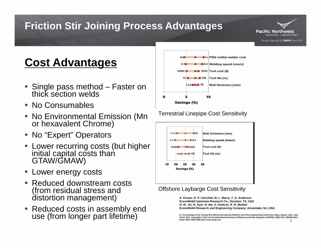
Cost Advantages
• Single pass method – Faster on thick section welds
• No Consumables• No Environmental Emission (Mn
or hexavalent Chrome)• No “Expert” Operators • Lower recurring costs (but higher
initial capital costs than GTAW/GMAW)
• Lower energy costs• Reduced downstream costs
(from residual stress and distortion management)
• Reduced costs in assembly end use (from longer part lifetime)
Terrestrial Linepipe Cost Sensitivity
A. Kumar, D. P. Fairchild, M. L. Macia, T. D. AndersonExxonMobil Upstream Research Co., Houston, TX, USAH. W. Jin, R. Ayer, N. Ma, A. Ozekcin, R. R. MuellerExxonMobil Research and Engineering Company, Annandale, NJ, USA:
in: Proceedings of the Twenty-first (2011) International Offshore and Polar Engineering Conference, Maui, Hawaii, USA, June 19-24, 2011, Copyright © 2011 by the International Society of Offshore and Polar Engineers (ISOPE), ISBN 978-1-880653-96-8 (Set); ISSN 1098-6189 (Set); www.isope.org
Offshore Laybarge Cost Sensitivity

• Welds up to 10mm are possible using commercial tooling with rough process already established for some alloys
• Welds 10mm to 13mm are less common, tools are available commercially, but process parameters need to be established for most alloys
• Welds above 13 mm (0.5”) have been demonstrated (up to 30mm), but very little knowledgebase on process robustness and tool durability
Typical macrostructure of a fully consolidated, defect-free steel FSW weld
Steel Friction Stir Welding – State of the Art
0.25”
Process Variables: Weld travel speed: 75 mm/min (3 ipm) to 250 mm/min (10 ipm)
Tool rotation Speed: 90 rpm to 600 rpm
Tool load: 13 kN (2900lbsf) to
67 kN (15000lbsf) for .75” thick welds
Process temperature: 700 C to 1100 C
Steel Thickness:
Tools:PCBN Convex scrolled shoulder stepped spiral pin tool or,
W‐Re HfC smooth pin, small shoulder
WRe Tool life: EWI recently showed88m in 19mm thick steel with a single tool

10
High Temperature Materials that can be FSW
Photo courtesy Brigham Young University
Production applications for steel FSW include pipe and tube manufacturing for the oil and gas industry (Global Tubing Inc.). TRL 7
Alloy 22 FSW showed only very fine intergranular TCP phases – no large grain boundary phases

Codes and Standards
Generalized Standards EffortsFSW rules language has been added to the new 2013 ASME Section IXAWS Subcommittee C6D – Best Practices Docs being writtenISO StandardSAE D17.1(aluminum)NASA (aluminum)MNPDS Mil Spec
Code Cases2 approved ASME Code cases running
WPS PQR Environments Qualification for Specific Applications or internal standards
11
FSW is poised for the TRL 4 to TRL 6 jump as a fabrication technology for power plant construction

FSW of NFA / ODS
Kanthal APMT
12

Friction Stir Welding of 20Cr-5Al-RE oxides Ferritic ODS (Kanthal APMT™)
20Cr 5Al Ferritic steel with good high temperature creep resistance and oxidation resistance similar to some Ni alloysGas atomized (RSP) product with some rare earth additions, not an MA ODS alloyAlumina former to protect against corrosion and carburization
13
Kanthal AB catalog 6-B-2-3 PM tubes, 11-08 3000
Oxid Met (2013) 79:29-39
10,0
00 h
r Cre
ep R
uptu
re
Designed for very high temperature applications in ethylene production tubing and heating elements
Material Fe Cr Al Mo REAPMT bal. 22 5 3 Added
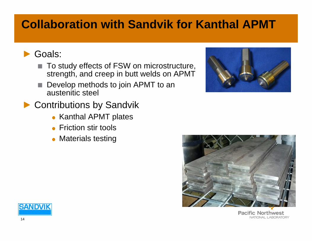
Collaboration with Sandvik for Kanthal APMT
Goals: To study effects of FSW on microstructure, strength, and creep in butt welds on APMT Develop methods to join APMT to an austenitic steel
Contributions by SandvikKanthal APMT platesFriction stir toolsMaterials testing
14

Typical microstructure of FSW APMT
15
Base metal Base metal
Weld Nugget

Mechanical properties of FSW APMT
RT Strength of FSW weld metal (only) is slightly improved over base metal, with a slight ductility drop
16
Yield strength Tensile strength Elongation HardnessRp0.2 Rm A
Material MPa MPa % HvLong. APMT Tube 540 740 26 250Long. FSW Plate 641 801 22 250‐290
Weld metal is slightly overmatched at RT

Creep Rupture Data
Solid lines are fit to data from cross weld tension creep tests on GTAW butt welded tube. (All these tests ruptured in weld metal)Dotted lines are fit to data from creep tests on FSW weld metal specimens extracted longitudinally from FSW weld metal onlyRed curves are tests at a higher test temperature than green curves
17
Log Time
Stre
ss
Test temperature >900 C
FSW weld metal shows a ~3X improvement in creep life when compared to GTAW weld metal

Nugget microstructure can be sensitive to weld process conditions
If we subject the weldment to a PWHT (1100ºC/1Hr) we can get different nugget microstructures depending on processing conditionsFSW process temperatures ranges investigated
Cold: <850ºCHot: >850ºC
We expect this to affect creep performance in this alloy in the same way it does in classically prepared MA ODS alloys – large grains are intentionally created by PWHT to enhance creep performance. Currently we have both microstructures in creep testing
18
As welded
Cold
As welded
Heat treated
Hot
Full grain growth after PWHT
No grain growth after PWHT
defect

Outline of Talk
FSW Overview / Potential Process Advantages Case Studies
FSW of NFA/ODSMA-956Kanthal APMT
FSW of Haynes 282 (Gamma prime strengthened nickel alloy) brief update FSW of P91(Modified)
19

Mechanical and Microstructural Evaluation of Friction Stir Processed Haynes® 282® Superalloy
Dr. Christian Widener; AMP Center DirectorDr. Michael West; REU Program DirectorDr. Bharat Jasthi; Research Scientist-III, AMP CenterIan Markon; Undergraduate Researcher
Advanced Materials Processing and Joining Laboratory
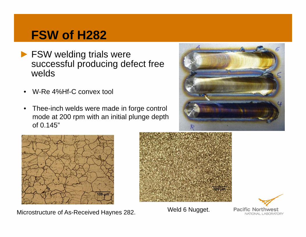
FSW of H282FSW welding trials were successful producing defect free welds
Microstructure of As-Received Haynes 282. Weld 6 Nugget.
• W-Re 4%Hf-C convex tool
• Thee-inch welds were made in forge control mode at 200 rpm with an initial plunge depth of 0.145”

Parent Parent + Aged
Grain size analysis of Haynes 282 after HTNo significant difference in grain size (average size ~ 59µm) observed after standard two-step aging treatment for Haynes 282: 1850F (1010°C)/2 hours/air cool + 1450°F (788°C)/8 hours/air cool
Nugget regions also show no significant difference in grain size with thermal aging. The average grain size is ~ 5 µm
FSW + HT

Transverse Tensile PropertiesFSW (200RPM, 1IPM, 1°tilt, 7500lbs force) results in higher YS and UTS but reduces elongation in both aged and un-aged conditions as compared to parent Haynes 282
Yield Strength(Ksi)
Ultimate Tensile Strength(Ksi)
% Elongation
Haynes 282 plate + Aged 103.7 166.4 30
Parent 60.7 117.1 64.9
Parent + Aged 89.2 158.0 34.5
FSW 65.6 123.2 29.3
FSW + Aged 101.6 163.4 13.1• Average of three samples per condition
Haynes published
values

Initial Creep Rupture Data
24
760 C
Red Squares are Base Metal data from HaynesThese data are projected points calculated from LM plots of base metal that has been SA then 2 step aged
Base metal SA +2step A Haynes data
point
Gas Metal Arc Weld – all weld metal specimen SA+ 2step aged Haynes data
FSW weld all weld metal specimen SA+2step A
FSW weld metal plots on trend with H282 base metalAll FSW weld metal has longer creep life than base metal at 760C / 345MPaFSW weld metal has slightly longer creep life than Fusion weld metal (despite very fine grain structure)
760C/345MPa: FSW SA + A = 576hrsH282 GMAW SA+A = 365hrsH282 SA+A = 238hrs

Outline of Talk
FSW Overview / Potential Process Advantages Case Studies
FSW of NFA/ODSKanthal APMT
FSW of Haynes 282 (Gamma prime strengthened nickel alloy) brief update FSW of P91(Modified)
25

Summary of progressFSW in P91 (Modified)
Creep Enhanced Ferritic

ASTM 387 Gr91 Class2 FSW Welds
Gr91 is easily FSW weldedDefect free welds in 10mm can be made at a wide range of process parametersTool temperatures can be maintained during welding at any point from 780C to 980 CTravel speeds are comparable to SMAW but process is single passThe hardness in the nugget region is increased as compared to the base metal, but not as much as in fusion welded nugget material prior to PWHT
27

Microstructure
28
nugget
“coarse” grained HAZ
Packet and lath sizes are much smaller than fusion welding in both the nugget and the HAZ
PAG: 20‐50 microns at center of nugget, much smaller everywhere else

FSW welds pass first level code requirements - Room Temperature Tensile
Room Temperature tensile results show Cross Weld Tensile specimens break in the parent material (yield and ultimate comparable to base metal)Failure location of FSW P91 is in the parent away from the HAZ on the advancing side of weld
29
Base metal
FSW
Sample
Yield Stress,
0.2% (ksi)
Ultimate Tensile
Stress (ksi)ASTM standard for A387‐G91,
class 2 plate 60 min. 85‐110Base metal P91 ‐ 1 72.1 95.1Base metal P91 ‐ 2 73.2 94.8
FSW P91 ‐ 1 79.5 98.8FSW P91 ‐ 2 80.1 99.8FSW P91 ‐ 3 80.0 99.8

30
Type IV Creep Failure.WSRF can be as low as 0.50 at long creep times (J. Parker, and others). This leads to greater allowances in pipe and tube wall thicknesses and/or reductions in operating temperature and/or pressure, with a reduction in plant efficiency.
Parker J, International Journal of Pressure Vessels and Piping (2012), http://dx.doi.org/10.1016/j.ijpvp.2012.11.004
FSW also shows type IV cracking
FSW also shows a low hardness zone
Slide from Mike Santella - ORNL04/19/2011
Performance issues with welded CSEF steelsProblem is not at room temperature
FSW130MPa, 625°C
100MPa, 625°C
Type IV failure

Why does Type IV develop?
Creep “softness” in the fine grained HAZ (Type IV failure)
31
Parker J, International Journal of Pressure Vessels and Piping (2012), http://dx.doi.org/10.1016/j.ijpvp.2012.11.004
CGHAZ: precipitate carbides dissolve – big PAGFGHAZ: not all precipitates dissolve- small PAGICHAZ: precipitates still around - incomplete transformation to austenite on heating –untempered martinsite islands This is the problem area in creep

FSW Gr91 shows much higher performance than fusion weld.
Creep results Gr91 cross FSW Weld Specimens
32
40
50
60
70
80
90
100
110
120
130
140
100 1,000 10,000
Stress (MPa)
Rupture Time (hrs)
P91 base metalGr91 FSW cross‐weldP91 Fusion cross‐weld
P91 base metal and cross weld fusion data from: V. Gaffard et al Nuclear Engineering and Design 235 (2005) 2547‐2562 FSW cross-weld Gr91 shows ~3X longer in creep life than fusion cross-weld P91 (SMAW with PWHT)
Design knockdown in strength is 32% for SMAW with PWHT (WSRF 0.68) vs. 18% for FSW (WSRF 0.82)
FSW was not subjected to PWHT

Why does FSW have a better weld strength reduction factor?
33
Lower peak temp and lower time at tempNo well developed CGHAZ
does not seem to reach temperature much above AC3 so precipitates that keep austenite grains small are still around. This leads to poorly developed CGHAZ. Mostly FNHAZMore gradual lath size variation across HAZMore gradual property gradient across HAZ
Narrow ICHAZ (geometric strengthening) from short time above ac1Lower residual stress
(esp important where combined serviceloads or geometry affects stress levels)

Another possible advantage over fusion welds
Cooling rate and time in the intercritical region can lead to incomplete transformation to austenite with heating in the ICHAZ, which leads to untempered martensite islands upon cooling. The size of the islands is affected by time at temperature and cooling rate. When subjected to later creep conditions the boundaries of the large packets are nucleation sites for creep cavities
34
FSW produces smaller prior austenite islands in the ICHAZ Less variation in lath size causes smaller stress concentrations, better resistance to cavitation
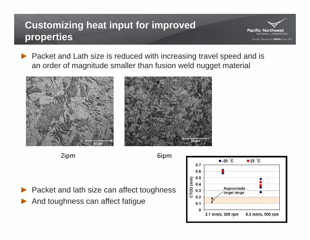
Packet and Lath size is reduced with increasing travel speed and is an order of magnitude smaller than fusion weld nugget material
Packet and lath size can affect toughnessAnd toughness can affect fatigue
35
Customizing heat input for improved properties

Can this be improved further?There is an optimum place for each property metric
In many material systems the FSW process window is largeA large process window means a wide range of weld specific power levels can be used and still result in a defect free weld We have seen many cases where the best performance in strength is located at a different place in the process space from other properties (toughness, ductility, hardness, or creep performance)
Best fracture toughness
Best room temperature strength FSW allows you to process the material across a wide range of specific power leading to different strains, temperatures, and thermal histories
With that you can optimized microstructures for the required property

Conclusions
CSEF steels are Friction Stir weldableCreep performance is very good, both of the weld metal and in cross weld tensionIt is possible that WSRF can be raised by more than 10% and it is possible that FSW will allow for a reduced requirement for PWHT Fatigue and creep fatigue are also important failure modes at nozzle or header pipe/manifold intersections due to cycling thermal stresses and pressure pulses in the supercritical fluid at constrictions and sharp radii. FSW, due to the refined microstructures in the joint area, may also be able to show improved properties for fatigue and toughness in these regions as well.FSW allows for enough knobs to be turned in the process to customized heat input. It may be possible to follow a path through thermo-mechanical space that will leave the weld region much closer to the parent microstructure than if it is fusion welded. 37

Conclusion - Next Steps
Kanthal APMT - New Project Partner SandvikWeld Metal performs on par with base material in creepAlready use this material in tube form in ethylene production and heater tubesCurrently APMT is a low cost, commercially available, ODS. The dispersoids and particles are not as fine as a typical NFA. But it may be “good enough” for some A-USC applications (not all components need 750/5000)FSW development for hot and cold processing conditions to determine effect on weld properties, grain growth, and creep strengthFSW joining of APMT to austenitic is in progressProject close at end of FY
H282Creep testing of FSW H282 weld metal at 760 C shows performance slightly better than base metal and GMAW weld metalCreep testing of cross weld specimens of FSW H282 in progress
Creep Enhanced Ferritics P91 (M) , Gr91FSW cross weld tension specimens have 3 times the rupture life of fusion welded (+PWHT) specimens, without any PWHT of the FSW weldFSW weld metal has an order of magnitude better creep life than the base metalCurrent FSW parameters show good potential to reduce Type IV Failure Starting new project in FY14 on P91,P92, P122, and Co/N modified ferritics
38

END
39