joint inspection best practices - ojua.org · acceptable to bond the mast through another...
TRANSCRIPT

Joint Inspection Best Practices 1st Edition – 2012 NESC
A publication of the Oregon Joint Use Association 1284 Court Street NE Salem Oregon 97301
503-378-0595 www.ojua.org Version 1.2, Winter 2016

This page intentionally left blank.

Joint Inspection Best Practices A Publication of the Oregon Joint Use Association
-i-
Table of Contents Joint Use NESC Inspections – General Information ............................................................................. 1
About This Manual .................................................................................................................................................1 Grandfathering (NESC 013B) ..................................................................................................................................1 Taking Measurements with a Measuring Stick .......................................................................................................1 Recommendations for Inspection Procedures .......................................................................................................1
Communication Worker Safety Zone (CWSZ) ..................................................................................... 3 CWSZ – At the Pole (40-inch) ..................................................................................................................................4 CWSZ – Midspan Pole to Pole .................................................................................................................................6 CWSZ – Midspan Pole-to-Service Entrance ............................................................................................................8 CWSZ – Street Light Clearances at the Pole ........................................................................................................ 11
CWSZ Streetlight Mast/Hardware ................................................................................................................... 12 CWSZ Streetlight Drip Loop ............................................................................................................................. 14
CWSZ – Service Entrance Meter Pole or Building ................................................................................................ 16 CWSZ – Service Entrance Clearance - Mast ......................................................................................................... 18 CWSZ – Other Midspan Clearances ..................................................................................................................... 21
CWSZ Midspan Clearance – Different Supporting Structures ......................................................................... 22 CWSZ Midspan Clearance – Supply Service Drop Passing Lateral Communication ........................................ 24
Communication-to-Communication Clearances ............................................................................... 27 Pole Vertical 12 Inches – Comm to Comm .......................................................................................................... 28 Midspan Vertical 4 Inches – Comm to Comm ..................................................................................................... 30
Interset Structure Clearances .......................................................................................................... 33 Interset Poles & Lights – Horizontal Clearance ................................................................................................... 34 Interset Poles & Lights – Vertical Clearance ........................................................................................................ 36
Other Condition Types .................................................................................................................... 39 Climbing Space – Communications ..................................................................................................................... 40 Climbable Structures ........................................................................................................................................... 42 Midspan Clearance – Conductor to Anchor Guy ................................................................................................. 44
Appendix – OJUA Codes, Abbreviations, and Sample Inspection Form ............................................. 47

Joint Inspection Best Practices A Publication of the Oregon Joint Use Association
-ii-
This page intentionally left blank.
Joint Inspection Best Practices A Publication of the Oregon Joint Use Association
-1-
Joint Use NESC Inspections – General Information About This Manual
• This manual does not address cost assignment. Parties are required to have agreements (contracts) that should outline the variables that determine who pays for corrective maintenance activities.
• The Suggested Best Practice may not be agreeable with all pole owners and licensees but has been reviewed by industry representative members of the OJUA from telephone, cable and electric utilities and is viewed as a practical overall recommendation that deserves consideration.
• Each scenario in this manual addresses a specific pole location and NESC condition and is not intended to represent all conditions of the same type.
Grandfathering (NESC 013B) • This manual should be used in conjunction with the OJUA Grandfather Matrix.
• Each scenario will indicate whether grandfathering is an option associated to the applicable NESC rule reference.
• Inspectors should be familiar with grandfathering options and apply it when allowable as the best practice but with primary regard for safety and system reliability.
Taking Measurements with a Measuring Stick • Clearances should be measured Surface to Surface per NESC Rule 230(3).
• When measuring the spacing of attachments at a pole and/or structure, measure Center to Center per NESC Rule 230(3).
• Place your measuring device on the highest point of ground near the pole on the side to be measured. Avoid any removable objects like loose rocks, excessive dirt piles, etc.
• Due to variation in stick manufacture, individual stick calibration is recommended.
• When measuring clearance between two aerial attachments, lightly set the hook of the measuring device on the bottom attachment then extend the device until the top of the hook touches the attachment above. Be sure to not move, pull down on, or raise attachments that are being measured as this can cause inaccurate measurements.
Recommendations for Inspection Procedures • Make sure that each inspector has a routine that they follow at every pole to ensure
consistent performance that considers all potential conditions and not just those that are visibly obvious. (For example, reviewing the condition of all wood, hardware and equipment attached, climbing quarter, clearances at the pole, clearances at midspan, conditions at the service entrance, etc. etc.)

Joint Inspection Best Practices A Publication of the Oregon Joint Use Association
-2-
• Require that all data be recorded in its final format (hardcopy or electronic device) at the time of inspection at the pole. Keeping shorthand notes and entering the official findings in the vehicle or office is not only inefficient, but will result in significant errors.
• If photos are included in the inspection process, outline a standard order in which they are taken at each location. (For example: 1st photo – pole identification number; 2nd photo – overview of entire pole; 3rd photo – close-up of conditions, etc. etc.)
Joint Inspection Best Practices A Publication of the Oregon Joint Use Association
-3-
Communication Worker Safety Zone (CWSZ) The Communication Worker Safety Zone (CWSZ) is defined in Rules 235C4 and 238E along with Tables 235-5, 238-1, and 238-2.
The NESC requires a Communication Worker Safety Zone on all poles jointly used to support supply and communication lines as well as anywhere in the span where supply and communication lines are with proximity of each other. This includes clearances at the pole (including street lights), midspan pole-to-pole, midspan pole-to-service entrance, and at the service entrance.
It should be noted that clearances at the pole (including street lights) are a vertical measurement, while all other clearances included in the Communication Worker Safety Zone are applicable “in any direction”.
Additional midspan clearances between supply and communication that are not included in the Communication Worker Safety Zone are illustrated in the Midspan Clearance section of this manual.

Joint Inspection Best Practices A Publication of the Oregon Joint Use Association
-4-
CWSZ – At the Pole (40-inch) OJUA Coding – PV, SEC, COML
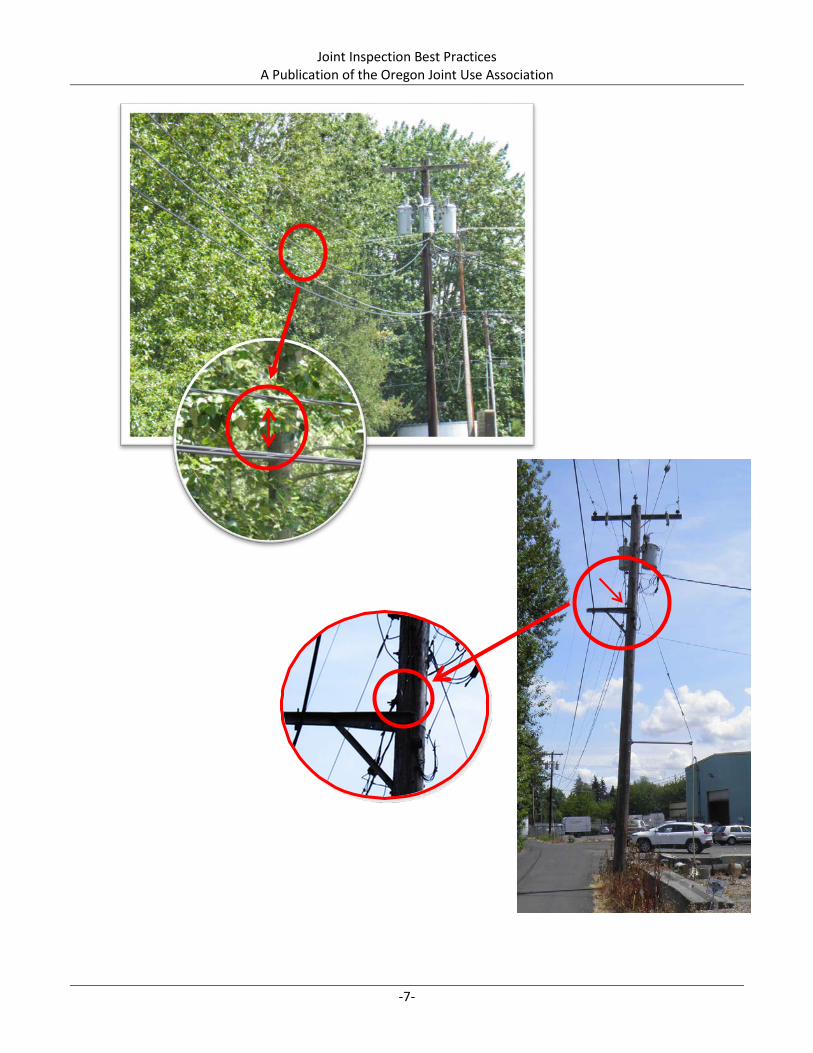
40 inches shall be maintained. No grandfathering. NESC Rule 235C1a, Table 235-5 (Row 1a), 235C4, 238B, Table 238-1, and 239G1 Supply lines and communication lines on the same supporting structure shall have vertical clearances no less than 40 inches. NOTE: Measurement is taken from lowest point of power to highest point of communication including hardware. ASSUMPTIONS: Driveway crossing midspan not shown in photos FACTS: 1. Lowest power measurement = 25 feet 7 inches 2. Highest comm measurement = 25 feet 6 inches (Cable TV) 3. Other comm measurements in violation Telco = 24 feet 8 inches & 23 feet 10 inches SUGGESTED BEST PRACTICE: 1) Seek coordination of lowering comms, sharing a cross arm and possibly extending power riser. 2) If ground clearances cannot be maintained, comms consider underground route.

Joint Inspection Best Practices A Publication of the Oregon Joint Use Association
-5-

Joint Inspection Best Practices A Publication of the Oregon Joint Use Association
-6-
CWSZ – Midspan Pole to Pole OJUA Coding – MV, SEC, COML
30 inches shall be maintained. No grandfathering. NESC Rule 235C2b(1)(a) Line wires, conductors, and cables supported at different levels on the same structures shall have vertical clearances at the supporting structures so adjusted that the clearance at any point in the span shall be not less than 75 percent of that required at the supports [40 inches] by Table 235-5 for voltages less than 50kV between conductors. ASSUMPTIONS: • Driveway is commercial and regular truck traffic is reasonably expected. • Communication provider attached directly to pole is most recent attachment and the only
non-compliant attachment. • Communication provider on the extension arm is compliant both at the pole and at
midspan. FACTS: 1. Lowest power measurement at midspan = 16 feet 7 inches 2. Highest comm measurement at midspan = 15 feet 3 inches (Cable TV) 3. Communication provider attached directly to pole has two associated conditions: Less than 30 inches to supply at midspan (NESC 235C2b(1)(a)) Less than 40 inches to supply at pole (NESC 235C1a, Table 235-5) SUGGESTED BEST PRACTICE: 1) Communication provider attached directly to pole should seek a joint arm agreement with other comm provider 2) If joint arm is not an option, consider underground route.
Joint Inspection Best Practices A Publication of the Oregon Joint Use Association
-7-

Joint Inspection Best Practices A Publication of the Oregon Joint Use Association
-8-
CWSZ – Midspan Pole-to-Service Entrance OJUA Coding – MV, COMD, PDRP
12 inches required between supply service drops and communication drops anywhere in the span between the supporting structure and the service entrance. NESC Rule 235C1, Exception 3 Supply service drops of 0 to 750V running above and parallel to communication service drops may have a clearance of not less than 12 inches at any point in the span including the point of their attachment to the building or structure being served provided that the nongrounded conductors are insulated and that the clearance as otherwise required by this rule is maintained between the two service drops at the pole. ASSUMPTIONS: • Midspan to Mast Scenario: Services are passing over driveway • Midspan to Structure Scenario: Services are passing over pedestrian-only surfaces FACTS: • Midspan to Mast Scenario Separation between supply and comm drops = 9 inches • Midspan to Structure Scenario Lowest separation point between supply and comm drops = 1.5 inches SUGGESTED BEST PRACTICES: Midspan to Mast Scenario: Remove comm drop from mast and relocate. Midspan to Structure Scenario: Move comm drop down on structure to create 12 inches separation.

Joint Inspection Best Practices A Publication of the Oregon Joint Use Association
-9-
9-inches
5-inches
1.5-inches
Mid
span
to M
ast
Mid
span
to S
truc
ture

Joint Inspection Best Practices A Publication of the Oregon Joint Use Association
-10-
This page intentionally left blank.
Joint Inspection Best Practices A Publication of the Oregon Joint Use Association
-11-
CWSZ – Street Light Clearances at the Pole Street lights are one of the few exceptions allowed to be placed inside the 40-inch Communication Worker Safety Zone. However, the NESC does have two separate rules related to clearances between street lights and communication attachments on the same structure. Both rules apply and cannot be separated. Rule 238C applies to the clearance requirement between the street light mast or hardware. A mast that is bonded to a ground wire allows for reduced clearances. It should be noted that when no vertical pole ground exists, bonding the mast to another effectively grounded line (such as the primary system neutral) is acceptable. Rule 238D applies to the clearance requirement between the street light service or drip loop. A covered drip loop allows for reduced clearances. It should be noted that there are many acceptable materials that qualify for a “suitable, non-metallic” covering. If a pole owner uses a rigid cover in normal practice, they may be willing to substitute a flexible cover when it assists in meeting requirements.

Joint Inspection Best Practices A Publication of the Oregon Joint Use Association
-12-
CWSZ Streetlight Mast/Hardware OJUA Coding – PV, COML, SLT
20 inches shall be maintained. See reduction allowances below. NESC Rule 238C Span wires or brackets carrying luminaires, traffic signals, or trolley conductors shall have at least the vertical clearances from communications equipment set forth in Table 238-2. Span wires and brackets not effectively grounded supporting luminaires above messengers carrying communication cables requires 20 inches clearance. If effectively grounded, 4 inches clearance is allowed. Span wires and brackets not effectively grounded supporting luminaires below messengers carrying communication cables requires 40 inches clearance. If effectively grounded, 4 inches clearance is allowed. NOTE: Communications attachments supported on cross arms require greater clearances. See Table 238-2. ASSUMPTIONS: • Communication attachments cannot be lowered due to roadway clearances. • Street light cannot be raised without compromising electric utility working space. FACTS: 1. There is a vertical pole ground 2. Separation between mast and highest comm = 5 inches 3. Separation between mast and lowest comm = 9 inches NOTE: In this scenario, the pole does have a vertical pole ground which makes bonding the mast the most practical solution. In the absence of an existing vertical pole ground, it is acceptable to bond the mast through another effectively grounded line, such as the primary system neutral. In cases where installation of a vertical pole ground is necessary in order to bond the mast, it may be cost beneficial to move communication attachments instead, whenever possible. SUGGESTED BEST PRACTICE: 1) Comm provider that owns the fiberglass arm at the level of the street light will need to move the arm down or use an alternate attachment type and stay below the street light. 2) Request that the light owner bond the mast. [This request can typically be made through the electric utility even when they do not own the lights.]

Joint Inspection Best Practices A Publication of the Oregon Joint Use Association
-13-
9-inches
5-inches
Mast not bonded to pole ground
*
*See Suggested Best Practice 1 on preceding page.

Joint Inspection Best Practices A Publication of the Oregon Joint Use Association
-14-
CWSZ Streetlight Drip Loop OJUA Coding – PV, COML, SLT
12 inches shall be maintained. See exception below. NESC Rule 238D If a drip loop of conductors entering a luminaire, a luminaire bracket, or a traffic signal bracket is above a communication cable, the lowest point of the loop shall be at least 12 inches above the highest communication cable, through bolt, or other exposed conductive objects. Exception: The above clearance may be reduced to 3 inches if the loop is covered by a suitable nonmetallic covering that extends at least 2 inches beyond the loop. NOTE: There is no stated clearance requirement for drip loops of luminaires below communication messengers. ASSUMPTIONS: • Comm cannot move down due to railroad and commercial driveway clearances. • Pole is owned by telephone. • Street light is permitted on pole. FACTS: 1. Separation between comm attachment point and covered drip loop = 1.5 inches 2. Mast is not bonded, which creates an additional and separate condition of Rule 238C. SUGGESTED BEST PRACTICE: Ask light owner if there is an alternate type of “suitable, nonmetallic” cover for the drip loop that will create the 3-inch separation needed and request that the mast be bonded.

Joint Inspection Best Practices A Publication of the Oregon Joint Use Association
-15-
Joint Inspection Best Practices A Publication of the Oregon Joint Use Association
-16-
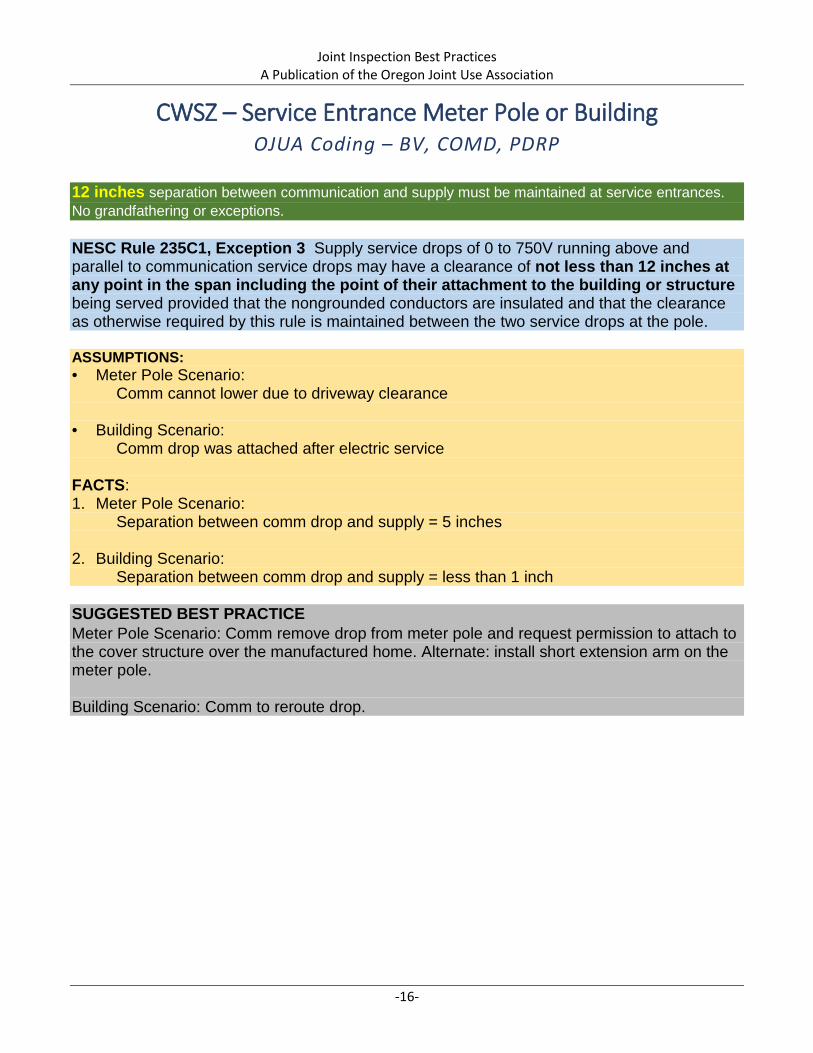
CWSZ – Service Entrance Meter Pole or Building OJUA Coding – BV, COMD, PDRP
12 inches separation between communication and supply must be maintained at service entrances. No grandfathering or exceptions. NESC Rule 235C1, Exception 3 Supply service drops of 0 to 750V running above and parallel to communication service drops may have a clearance of not less than 12 inches at any point in the span including the point of their attachment to the building or structure being served provided that the nongrounded conductors are insulated and that the clearance as otherwise required by this rule is maintained between the two service drops at the pole. ASSUMPTIONS: • Meter Pole Scenario: Comm cannot lower due to driveway clearance • Building Scenario: Comm drop was attached after electric service FACTS: 1. Meter Pole Scenario: Separation between comm drop and supply = 5 inches 2. Building Scenario: Separation between comm drop and supply = less than 1 inch SUGGESTED BEST PRACTICE Meter Pole Scenario: Comm remove drop from meter pole and request permission to attach to the cover structure over the manufactured home. Alternate: install short extension arm on the meter pole. Building Scenario: Comm to reroute drop.

Joint Inspection Best Practices A Publication of the Oregon Joint Use Association
-17-
At
Met
er P
ole
At B
uild
ing
6 inches
Joint Inspection Best Practices A Publication of the Oregon Joint Use Association
-18-
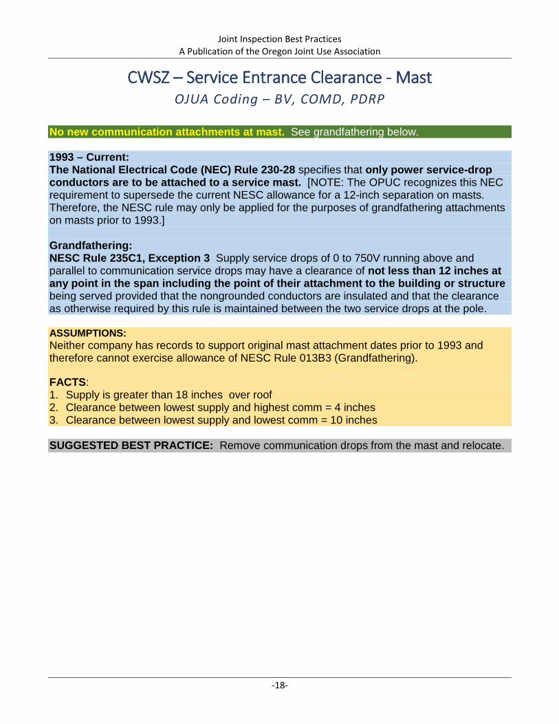
CWSZ – Service Entrance Clearance - Mast OJUA Coding – BV, COMD, PDRP
No new communication attachments at mast. See grandfathering below. 1993 – Current: The National Electrical Code (NEC) Rule 230-28 specifies that only power service-drop conductors are to be attached to a service mast. [NOTE: The OPUC recognizes this NEC requirement to supersede the current NESC allowance for a 12-inch separation on masts. Therefore, the NESC rule may only be applied for the purposes of grandfathering attachments on masts prior to 1993.] Grandfathering: NESC Rule 235C1, Exception 3 Supply service drops of 0 to 750V running above and parallel to communication service drops may have a clearance of not less than 12 inches at any point in the span including the point of their attachment to the building or structure being served provided that the nongrounded conductors are insulated and that the clearance as otherwise required by this rule is maintained between the two service drops at the pole. ASSUMPTIONS: Neither company has records to support original mast attachment dates prior to 1993 and therefore cannot exercise allowance of NESC Rule 013B3 (Grandfathering). FACTS: 1. Supply is greater than 18 inches over roof 2. Clearance between lowest supply and highest comm = 4 inches 3. Clearance between lowest supply and lowest comm = 10 inches SUGGESTED BEST PRACTICE: Remove communication drops from the mast and relocate.

Joint Inspection Best Practices A Publication of the Oregon Joint Use Association
-19-
4-inches
10-inches
Joint Inspection Best Practices A Publication of the Oregon Joint Use Association
-20-
This page intentionally left blank.

Joint Inspection Best Practices A Publication of the Oregon Joint Use Association
-21-
CWSZ – Other Midspan Clearances In addition to the Communication Worker Safety Zone, there are clearance requirements between supply and communication facilities when:
1. Supported by different structures and crossing each other at midspan (Rule 233C1), and
2. Supply service drops pass by lateral communication attachments supported on the same structure (Rule 235E1).
a. For clearances of supply drops attached vertically on the pole and running through communication attachment space, see Rule 239G.

Joint Inspection Best Practices A Publication of the Oregon Joint Use Association
-22-
CWSZ Midspan Clearance – Different Supporting Structures OJUA Coding – MV, PDRP, COML
24 inches required at crossings between any type of wires or conductors carried on different supporting structures. See footnote reference below for reduction between communication conductors. NESC Rule 233C1, Table 233-1 The vertical clearance between any crossing or adjacent wires, conductors, or cables carried on different supporting structures shall be not less than that shown in Table 233-1.
Footnote 2: The clearance of communication conductors and their guy span and messenger wires from each other in locations where no other classes of conductors are involved may be reduced by mutual consent of parties concerned, except for fire alarm or railroad conductors. ASSUMPTIONS: • Communication cannot move down due to road clearance requirements. • For aesthetic reasons, customer does not want a taller mast even if cost is covered. FACTS: Vertical separation between supply svc and comm messenger = 9 inches SUGGESTED BEST PRACTICE: Electric utility should request permit for a pole top extension that would allow 40 inches separation on telephone pole until such time that the pole requires replacement.

Joint Inspection Best Practices A Publication of the Oregon Joint Use Association
-23-
Vertical clearance between supply service and comm messenger is 9”

Joint Inspection Best Practices A Publication of the Oregon Joint Use Association
-24-
CWSZ Midspan Clearance – Supply Service Drop Passing Lateral Communication
OJUA Coding – MV, PDRP, COML
30 inches required when there is a communication messenger attached pole-to-pole and a supply service drop passing by the communication space as it runs from pole-to-point of service. No exceptions. See Grandfathering below. 2012 - Current NESC Rule 235E1, Table 235-6, Row 5b Clearances in any direction at or near a support from line conductors to supports, and to vertical or lateral conductors, service drops, and span or guy wires, attached to the same support shall be not less than those given in Table 235-6. Table 235-6, Row 5b (Supply service drops in the span) and column titled “Communication lines on jointly used structures” requires 30 inches. Grandfathering Pre-2012: No specific NESC rule requirements. Use Rule 012C and maintain best available clearance or, when practical, follow Rule 239G1&2 which specifies the requirements for covering supply cables that pass vertically through the communication space and are attached directly to the pole. ASSUMPTIONS: • Condition does not qualify for grandfathering because communication attachment was
made after 2011. • Communication attachment cannot be moved far enough down the pole to gain necessary
clearance without causing ground clearance condition. • Midspan crossing over agricultural equipment entrance. FACTS: Separation between supply service and communication = 4 inches. SUGGESTED BEST PRACTICE: Move supply service attachment to field side of the pole and replace eye bolt with an extension arm to maintain 30 inches clearances passing by lateral communication attachment.

Joint Inspection Best Practices A Publication of the Oregon Joint Use Association
-25-
.

Joint Inspection Best Practices A Publication of the Oregon Joint Use Association
-26-
This page intentionally left blank.
Joint Inspection Best Practices A Publication of the Oregon Joint Use Association
-27-
Communication-to-Communication Clearances Clearances between communication providers, both at the pole and at midspan, became an NESC requirement in 2007. These requirements are covered by Rule 235H and agreement between all affected parties is required, including the pole owner (as of 2012). When performing inspections, consideration of grandfathering as it applies to this rule is especially important. Much of the construction performed prior to 2007 will not meet current requirements.

Joint Inspection Best Practices A Publication of the Oregon Joint Use Association
-28-
Pole Vertical 12 Inches – Comm to Comm OJUA Coding – PV, COML, COML
12 inches shall be maintained. See reduction allowances below. NESC Rule 235H1 The spacing between messengers supporting communication cables should not be less than 12 inches except by agreement between the parties involved including the pole owner(s). ASSUMPTIONS: • Lowest comm midspan crossing street at 19 feet not shown in photos • No midspan clearance issues with power or comms FACTS: 1. Lowest power measurement = 25 feet 4 inches 2. Highest comm measurement = 20 feet 10 inches (Cable TV) 3. Lowest comm measurement = 20 feet 1 inches SUGGESTED BEST PRACTICE: Highest or lowest comm raise or lower, respectively.

Joint Inspection Best Practices A Publication of the Oregon Joint Use Association
-29-
9-inches

Joint Inspection Best Practices A Publication of the Oregon Joint Use Association
-30-
Midspan Vertical 4 Inches – Comm to Comm OJUA Coding – MV, COML, COML
4 inches shall be maintained. See reduction allowances below. NESC Rule 235H2 The clearances between the conductors, cables, and equipment of one communication utility to those of another, anywhere in the span, shall be not less than 4 inches, except by agreement between the parties involved including the pole owner(s). ASSUMPTIONS: • Lowest comm midspan crossing street South of the pole not shown in photos • Driveway crossing near the base of the pole FACTS: 1. Lowest power measurement = 28 feet 6 inches 2. Highest comm measurement = 24 feet 2 inches (Cable TV) 3. Lowest comm measurement = 23 feet 11 inches 4. Another lower comm may be attaching or removing = 20 feet 5 inches 5. Midspans over street Power = 25 feet 10 inches Highest comm = 17 feet 11 inches Lowest comm = 18 feet 4 inches SUGGESTED BEST PRACTICE: Lowest comm re-sag span to lower and obtain 4 inches separation.

Joint Inspection Best Practices A Publication of the Oregon Joint Use Association
-31-
Wires switch high/low positions midspan

Joint Inspection Best Practices A Publication of the Oregon Joint Use Association
-32-
This page intentionally left blank.

Joint Inspection Best Practices A Publication of the Oregon Joint Use Association
-33-
Interset Structure Clearances Scenarios on the following pages apply to poles, standalone street lights and other interset structures where wires pass by but are not attached. Both Rules 234B1 and 234B2 apply; however, it is only necessary to meet one of the two requirements. Rule 234B1 addresses horizontal clearance requirements for wires that are not attached to the midspan structure. Rule 234B2 addresses vertical clearance requirements for wires that are not attached to the midspan structure. If a wire meets the horizontal clearance requirement, it does not have to meet the vertical requirement and vice versa.
Joint Inspection Best Practices A Publication of the Oregon Joint Use Association
-34-
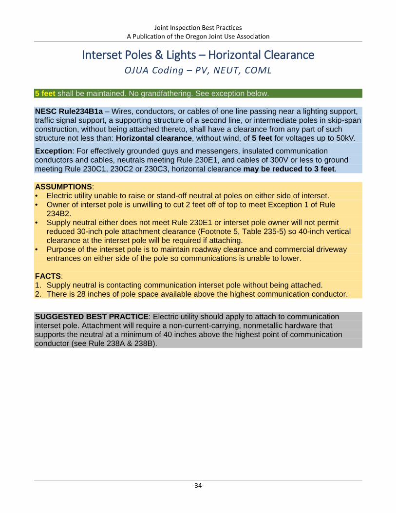
Interset Poles & Lights – Horizontal Clearance OJUA Coding – PV, NEUT, COML
5 feet shall be maintained. No grandfathering. See exception below. NESC Rule234B1a – Wires, conductors, or cables of one line passing near a lighting support, traffic signal support, a supporting structure of a second line, or intermediate poles in skip-span construction, without being attached thereto, shall have a clearance from any part of such structure not less than: Horizontal clearance, without wind, of 5 feet for voltages up to 50kV. Exception: For effectively grounded guys and messengers, insulated communication conductors and cables, neutrals meeting Rule 230E1, and cables of 300V or less to ground meeting Rule 230C1, 230C2 or 230C3, horizontal clearance may be reduced to 3 feet. ASSUMPTIONS: • Electric utility unable to raise or stand-off neutral at poles on either side of interset. • Owner of interset pole is unwilling to cut 2 feet off of top to meet Exception 1 of Rule
234B2. • Supply neutral either does not meet Rule 230E1 or interset pole owner will not permit
reduced 30-inch pole attachment clearance (Footnote 5, Table 235-5) so 40-inch vertical clearance at the interset pole will be required if attaching.
• Purpose of the interset pole is to maintain roadway clearance and commercial driveway entrances on either side of the pole so communications is unable to lower.
FACTS: 1. Supply neutral is contacting communication interset pole without being attached. 2. There is 28 inches of pole space available above the highest communication conductor.
SUGGESTED BEST PRACTICE: Electric utility should apply to attach to communication interset pole. Attachment will require a non-current-carrying, nonmetallic hardware that supports the neutral at a minimum of 40 inches above the highest point of communication conductor (see Rule 238A & 238B).

Joint Inspection Best Practices A Publication of the Oregon Joint Use Association
-35-
28 inches

Joint Inspection Best Practices A Publication of the Oregon Joint Use Association
-36-
Interset Poles & Lights – Vertical Clearance OJUA Coding – MV, NEUT, MPOL
4.5 feet shall be maintained. No grandfathering. See exception below NESC Rule 234B2 – Wires, conductors, or cables of one line passing near a lighting support, traffic signal support, a supporting structure of a second line, or intermediate poles in skip-span construction, without being attached thereto, shall have a clearance from any part of such structure not less than: Vertical clearance of 4.5 feet for voltages below 22 kV and a vertical clearance of 5.5 feet for voltages between 22 kV and 50 kV. Exception 1: For effectively grounded guys and messengers, insulated communication conductors and cables, and neutrals meeting Rule 230E1 and for cables of 300 V or less to ground meeting the requirements of Rule 230C1, 230C2 or 230C3, the vertical clearance may be reduced to 2 feet. ASSUMPTIONS: • Right-of-way will give priority to traffic signal circuit pole. • Attachment to the traffic signal circuit pole will not be permitted. FACTS: 1. Supply neutral is 6 inches above and 15 inches to the side of the traffic signal circuit pole. 2. Comm messenger is 15 inches to the side of the traffic signal circuit pole (Rule 234B1a). SUGGESTED BEST PRACTICE: Supply may have the option of raising the neutral on the primary pole that is on the opposite side of the intersection to gain 2 feet vertically over the traffic signal circuit pole. If not, placing the neutral on an extension arm on both primary poles to gain 3 feet horizontal clearance is recommended. Communication may have the option to serve the customer from another route and remove the span in conflict. If not, placing the communication on a cross arm or extension arm to gain 3 feet horizontal clearance either side of the traffic signal circuit pole is recommended.

Joint Inspection Best Practices A Publication of the Oregon Joint Use Association
-37-
Comm messenger is 15” to the side of the traffic signal circuit pole.
Supply neutral is 6” above and 15” to the side of the traffic signal circuit pole.
Joint Inspection Best Practices A Publication of the Oregon Joint Use Association
-38-
This page intentionally left blank.
Joint Inspection Best Practices A Publication of the Oregon Joint Use Association
-39-
Other Condition Types Climbing Space, Climbable Structures and Communication or Supply Conductors contacting Guys are all NESC conditions.
Additional Information Regarding Climbing Space: The requirement for unobstructed climbing space is covered in NESC Rule 236.
While it is true that the majority of utility work on poles is now accomplished using ladders and bucket trucks, climbing space is still of critical importance in cases such as access restrictions, weather-related events, and emergency rescue of co-workers.
Joint Inspection Best Practices A Publication of the Oregon Joint Use Association
-40-
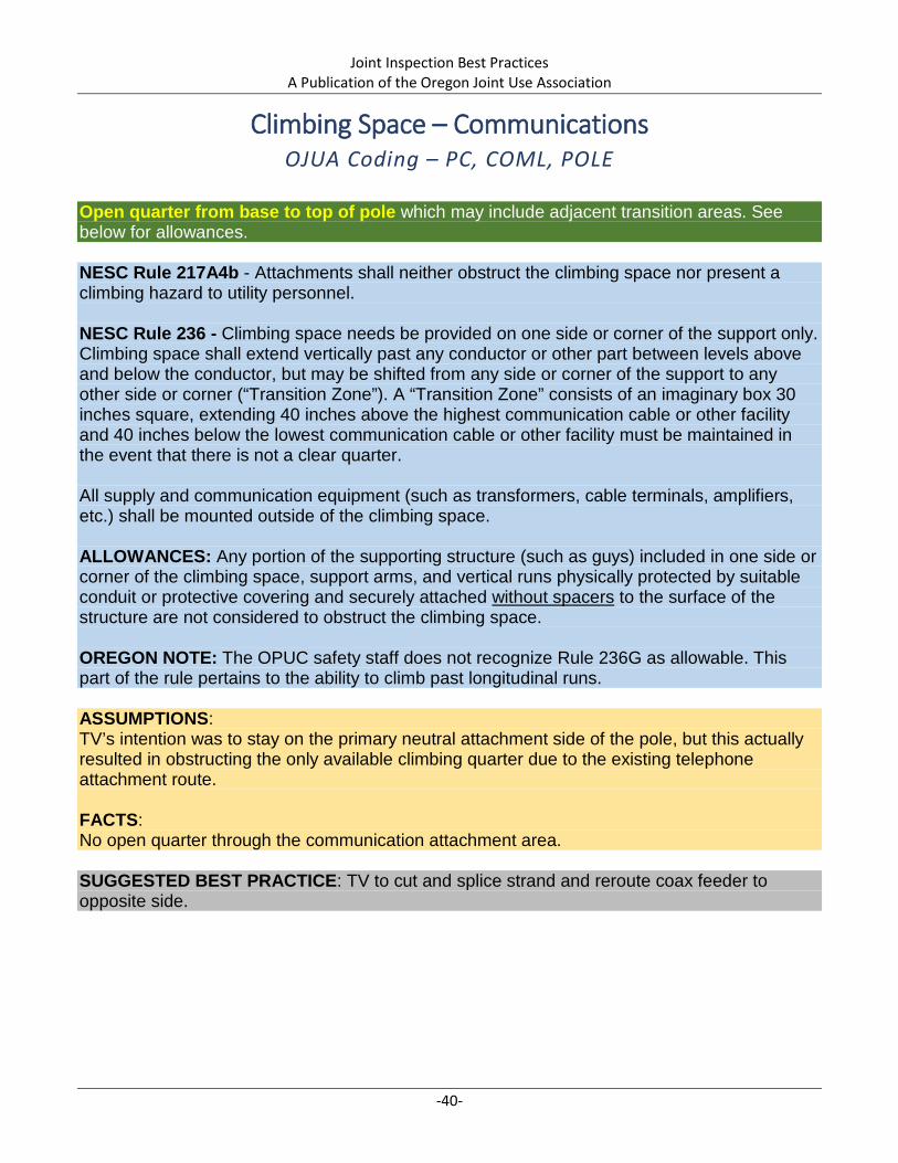
Climbing Space – Communications OJUA Coding – PC, COML, POLE
Open quarter from base to top of pole which may include adjacent transition areas. See below for allowances. NESC Rule 217A4b - Attachments shall neither obstruct the climbing space nor present a climbing hazard to utility personnel. NESC Rule 236 - Climbing space needs be provided on one side or corner of the support only. Climbing space shall extend vertically past any conductor or other part between levels above and below the conductor, but may be shifted from any side or corner of the support to any other side or corner (“Transition Zone”). A “Transition Zone” consists of an imaginary box 30 inches square, extending 40 inches above the highest communication cable or other facility and 40 inches below the lowest communication cable or other facility must be maintained in the event that there is not a clear quarter. All supply and communication equipment (such as transformers, cable terminals, amplifiers, etc.) shall be mounted outside of the climbing space. ALLOWANCES: Any portion of the supporting structure (such as guys) included in one side or corner of the climbing space, support arms, and vertical runs physically protected by suitable conduit or protective covering and securely attached without spacers to the surface of the structure are not considered to obstruct the climbing space. OREGON NOTE: The OPUC safety staff does not recognize Rule 236G as allowable. This part of the rule pertains to the ability to climb past longitudinal runs. ASSUMPTIONS: TV’s intention was to stay on the primary neutral attachment side of the pole, but this actually resulted in obstructing the only available climbing quarter due to the existing telephone attachment route. FACTS: No open quarter through the communication attachment area. SUGGESTED BEST PRACTICE: TV to cut and splice strand and reroute coax feeder to opposite side.

Joint Inspection Best Practices A Publication of the Oregon Joint Use Association
-41-
Facing North
Facing South

Joint Inspection Best Practices A Publication of the Oregon Joint Use Association
-42-
Climbable Structures OJUA Coding – RIS, SOB, SOB
8 feet separation required from lowest accessible surface to next handhold. NESC Rule 217A2c Standoff brackets on supporting structures shall be arranged so that there is not less than 8 feet between either: 1) The lowest bracket and ground or other accessible surface, or 2) The lowest two brackets. Exception: This rule does not apply where supporting structures are isolated. FACTS: Lowest bracket measurement = 6 feet 10 inches Next handhold measurement = 13 feet 1 inch [6 feet 3 inches separation from lowest bracket Second bracket measurement = 13 feet 8 inches [6 feet 10 inches separation from lowest bracket]
SUGGESTED BEST PRACTICE: Depending on the location of the conduit joints, either lower the bottom bracket to create at least 8 feet separation to the next reachable support or raise the bottom bracket to create at least 8 feet clearance above ground.

Joint Inspection Best Practices A Publication of the Oregon Joint Use Association
-43-
6 feet 10 inches
13 feet 8 inches 13 feet
1inch

Joint Inspection Best Practices A Publication of the Oregon Joint Use Association
-44-
Midspan Clearance – Conductor to Anchor Guy OJUA Coding – MH, COML, GUY
6 inches required between conductors and anchor guys on jointly used structures. No grandfathering. See allowances below. NESC Rule 235E1, Table 235-6, Row 2b Clearances in any direction at or near a support from line conductors to supports, and to vertical or lateral conductors, service drops, and span or guy wires, attached to the same support shall be not less than 6 inches. Footnote 1: For guy wires, if practical. For clearances between span wires and communication conductors, see Rule 238C. On jointly used structures, guys that pass within 12 inches of supply conductors, and also pass within 12 inches of communication cables, shall be protected with a suitable insulating covering where the guy passes the supply conductors, unless the guy is effectively grounded or insulated with a strain insulator at a point below the lowest supply conductor and above the highest communication cable. The clearance from an insulated or effectively grounded guy to a communication cable may be reduced to 3 inches when abrasion protection is provided on the guy or communication cable. ASSUMPTIONS: Changing the location of the guy is not a practical solution. FACTS: Communication messenger is contacting the anchor guy. SUGGESTED BEST PRACTICE: Put communication messenger on an extension arm.

Joint Inspection Best Practices A Publication of the Oregon Joint Use Association
-45-

Joint Inspection Best Practices A Publication of the Oregon Joint Use Association
-46-
This page intentionally left blank.
Joint Inspection Best Practices A Publication of the Oregon Joint Use Association
-47-
Appendix – OJUA Codes, Abbreviations, and Sample Inspection Form
Originally published in 2005, the OJUA Codes & Abbreviations provide a convenient short-hand method of identifying deviations, attachments, and equipment associated with joint use programs. Use of these codes and abbreviations and the following inspection form are not required; they are available for use by any organization that may not already have a similar process in place.

Attachment Type (Type) Code Equipment (EQUIP. 1 & 2) Code Equipment (continued) Code Suggested ActionAntennas ANT Anchor ANC Riser RIS AttachCommunication Cross-Connect XBOX Anchor (auxiliary) AANC Roof ROOF Attach Mid-spanCommunication Drop COMD Antennas ANT Sidewalk Fixture SWF BuryCommunication Equipment (other) CEO Bridge BR Signs SIGN Contact Jump PoleCommunication Fiber-optic COFO Communication Bridle Wire BWR Stand Off Brackets SOB Ground/BondCommunication Load Coil LOAD Communication Cross-Connect XBOX Stencils/Pole Tag STN GuardCommunication Mainline COML Communication C-Wire CWR Subscriber Network Interface SNI LengthenCommunication Messenger COMM Communication Drop COMD Supply Fiber-optic SPFO LowerCommunication Power Supply PS Communication Equipment (other) CEO Traffic Signal Bracket TRSB Lower CATVCommunication Repeater REP Communication Fiber-optic COFO Traffic Signals TRS Lower FiberCommunication Terminal TRM Communication Load Coil LOAD Trees/Vegetation TREE Lower NeutralConduit-metal MCON Communication Mainline COML U-Guard UGRD Lower OtherConduit-PVC CON Communication Messenger COMM Inaccessible Surface UNSR Lower PowerCross-arm XARM Communication Power Supply PS Water Surface WSR Lower SecondaryCross-arm (fiberglass) XARF Communication Repeater REP Weather Head WH Lower TelcoDown Guy GUY Communication Terminal TRM Window WIN Make ReadyFiber Equipment (other) FEO Conduit-metal MCON Wireless Equipment (other) WEO Move 1st attachmentOthers Mainline OTML Conduit-PVC CON Move Mid-spanOthers Messenger OTMM Cross-arm XARM Move to SpanOverhead Guy OGUY Cross-arm (fiberglass) XARF PlacePedestal PED Cross-arm Braces XARB Base Pole Info Place BSW (buried service wire)
Platform PF Curb CURB Timber Species (Material) Code Place California TopPole to Pole Guy PPG Down Guy GUY Douglas fir DF Place Clearance PolePower Meter PMR Drivable Surface DRSR Concrete CC Place Cross-armPower Neutral NEUT Fence FENC Fiberglass FG Place Mid-set PolePower Primary PRI Fiber Equipment (other) FEO Jack Pine JP Place Split DuctPower Secondary SEC Fire Hydrant HYD Laminated LM Place Taller PolePower Service Drop PDRP Ground Rod GRND Lodgepole Pine LP RaisePower Service Support Wire PSSW Ground Wire GRWR Metal/Steel ST Raise CATVPower Street Light SLT Guy Marker GM Ponderosa Pine WP Raise FiberPower Switch SWCH Hardware HDWR Red Pine NP Raise NeutralPower Transformer XFMR Insulator INS Southern Pine SP Raise OtherPrivate Party Attachment PVT Lashing Wire LWR Southern Yellow Pine SYP Raise PowerRiser RIS Multi-grounded Neutral MGN Western Larch WL Raise SecondarySigns SIGN Others Mainline OTML Western Red Cedar WC Raise TelcoStand Off Brackets SOB Others Messenger OTMM Refer to EngineeringSupply Fiber-optic SPFO Overhead Guy OGUY Relocate/MoveTraffic Signal Bracket TRSB Padmount Equipment PAD RemoveTraffic Signals TRS Pedestal PED RepairWireless Equipment (other) WEO Pedestrian Surface PEDS Replace
Platform PF Directional Information Abbrev. Re-TensionPole POLE North N Shorten
Deviation Code (DEV.) Code Pole Step STEP South S TightenAbandoned AB Pole to Pole Guy PPG East E TransferBuilding BD Pole-Metal MPOL West W TrimBuilding/Horizontal clearance BH Power Bracket PBRK North East NEBuilding/Vertical clearance BV Power Capacitor PCAP South East SEDamaged/Broken DB Power Drip-loop PDLP North West NWMid-span/Horizontal clearance MH Power Jumpers JUMP South West SWMid-span/Vertical clearance MV Power Mast PMST North Side N/SMissing MS Power Meter PMR South Side S/SOut of Lead OL Power Neutral NEUT East Side E/SPole Leaning PL Power Primary PRI West Side W/SPole/Climbing/working space PC Power Secondary SEC Field Side F/SPole/Grounding PG Power Service Drop PDRP Road Side R/SPole/Horizontal clearance PH Power Service Support Wire/Bridle PSSW North Of N/OPole/Marking PM Power Street Light SLT South Of S/OPole/Riser PR Power Switch SWCH East Of E/OPole/Structure PS Power Transformer XFMR West Of W/OPole/Vertical clearance PV Private Party Attachment PVT Rear Of R/OUnderground U Railroad RR Across From A/F
ViolationsAbbreviations & Codes for Attachments, Violations/Deviations, and Equipment
Attachments
Violations
Base Pole Info

Comments
Request Field Meet
Base Pole Info
Inspection Type
Anchors
Guys
Attachments
ViolationsU.C. Dev. Equip. 1 Equip. 2 Suggested Action
Type Height Comments U.C. Comments
U.C. Size Type Height Lead Insulated Bonded Comments
U.C. Rod Size Eye Type U.C. Rod Size Eye Type
U.C. U.C.
U.C. Rod Size Eye Type U.C. Rod Size Eye Type
U.C. U.C. U.C.
Number U.C. Map Number
NESC ReferenceSEV.Toward
Inspection End Time
U.C.
U.C.U.C. Map
Type Height
U.C. Number
Access Issues
Inspection Company
Zip CodeLatitude
AddressHeight Class
Comments
CityLongitude
Wire Center
Street CodeNumber
Year Set Material
NJUNS Number
Inspector Last First Inspection Start TimeInspection Date
Post Construction DetailedPre Construction Safety
Not On Map Not in field Double Pole Transfer
Power Telco CATV Other
Quality Control
Telco Owned CATV OwnedPower Owned Other Owned
Double Pole Transfer