joint restraint (4 - 24) - us pipe · joint restraint (4" - 24") field lok 350 ... north...
TRANSCRIPT
FOR WATER & WASTEWATER, FIRE PROTECTION & INDUSTRIAL APPLICATIONSNSF®Certified to
ANSI/NSF 61
JOINT RESTRAINT (4" - 24")
FIELD LOK 350®
-Red Gasket
FIELD LOK 350-Red GasketNSF®
Certified toANSI/NSF 61
P 2866.
DIP.
PIPE
REVISED 05.17U.S. PIPE AND FOUNDRY CO. FIELD LOK 350® Red Gasket BRO-001
4"–24"
2 0 1 7 E D I T I O N
®
FIELD LOK 350® Gasket 3
Assembly 4
Alternative Assembly Methods 7
Pipe Diameters 8
Assembly Mark and Deflection 8
Special Notes Regarding the Use of FIELD LOK 350 Gaskets 9
Disassembly for All Sizes 11
Products for Water, Waste Water and Fire Protection 12
Table of Contents
FIELD LOK 350-Red GasketNSF®
Certified toANSI/NSF 61
P 3866.
DIP.
PIPE
REVISED 05.17U.S. PIPE AND FOUNDRY CO. FIELD LOK 350® Red Gasket BRO-001
4"–24"
2 0 1 7 E D I T I O N
®
Restrained joint pipe and fittings are used in pressurized Ductile Iron pipelines to prevent the joints of the line from separating due to thrust forces. Thrust forces generally occur at changes of direction in the line. Usually, a calculated length of pipeline extending from the location of the thrust force is restrained in the joints so that this force can be transmitted to the soil surrounding the line. The entire pipeline is often restrained for installations in poor soil or for crit-ical lines.
U.S. Pipe’s FIELD LOK 350 Gasket has proven to be an extremely successful, trouble-free means of joint restraint for well over one million Ductile Iron pipe and fitting joint assemblies across North America. By simply inserting a FIELD LOK 350 Gasket into the socket of a TYTON JOINT® Pipe, Fitting or Valve, restraint is instantly achieved when the joint is assembled. Stainless steel locking segments vulcanized into the FIELD LOK 350 Gasket grip the pipe to prevent joint separation.
FIELD LOK 350 Gaskets, utilizing patented improvements, are rated by U.S. Pipe for operating pressures up to 350 psi — a rating that now matches that of Pressure Class 350 pipe — giving the engineer and user new flexibility in designing piping systems.
Underwriters Laboratories lists the 4"–24" sizes for 350 psi. Factory Mutual, utilizing a safety factor of 4, approves the 4"–16" sizes for 250 psi and the 18"–24" sizes for 200 psi service.
With the use of the FIELD LOK 350 Gasket, push-on joint Ductile Iron TYTON JOINT Pipe or Fittings can be quickly and securely restrained as the joint is assembled. The restraint provided shall be a boltless, integral restraining system and shall be rated for 350 psi in accordance with the per-formance requirements of ANSI/AWWA C111/A21.11. Field cut pipe are no longer a problem to restrain. No pipe surface preparation* or grooving is required for field cut pipe other than the cut end needing to be beveled as required for any push-on joint spigot end. With the FIELD LOK 350 Gasket in place, the joints are restrained without thrust blocks, bolts, grooves, rods, clamps or retainer glands, resulting in savings of labor, material and time.
CAUTION: U.S. Pipe does not recommend FIELD LOK 350 Gaskets for use above ground. The long-term effect of cyclical movements can be gradual joint separation to the point that the seal on the gasket bulb is compromised. Sources of cyclical movements include vibration as may be found on bridge crossings, and thermal expansion and contraction resulting from atmospheric temperature changes. These conditions are not experienced with buried pipe lines.
*See note on page 5 regarding pipe with thick coatings or tape wrap.
FIELD LOK ®, FIELD LOK 350 ®, TYTON ®, TYTON JOINT ® and TR FLEX ® are Registered Trademarks of U.S. Pipe and Foundry Company.
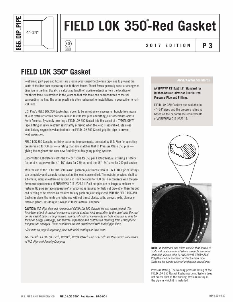
ANSI/AWWA C111/A21.11 Standard for Rubber-Gasket Joints for Ductile Iron Pressure Pipe and Fittings.
FIELD LOK 350 Gaskets are available in 4"–24" sizes and the pressure rating is based on the performance requirements of ANSI/AWWA C111/A21.11.
ANSI /AWWA Standards
NOTE: If specifiers and users believe that corrosive soils will be encountered where products are to be installed, please refer to ANSI/AWWA C105/A21.5 Polyethylene Encasement for Ductile Iron Pipe Systems for proper external protection procedures.
Pressure Rating: The working pressure rating of the FIELD LOK 350 Gasket Restrained Joint System does not exceed that of the working pressure rating of the pipe in which it is installed.
FIELD LOK 350® Gasket
FIELD LOK 350-Red GasketNSF®
Certified toANSI/NSF 61
P 4866.
DIP.
PIPE
REVISED 05.17U.S. PIPE AND FOUNDRY CO. FIELD LOK 350® Red Gasket BRO-001
4"–24"
2 0 1 7 E D I T I O N
®
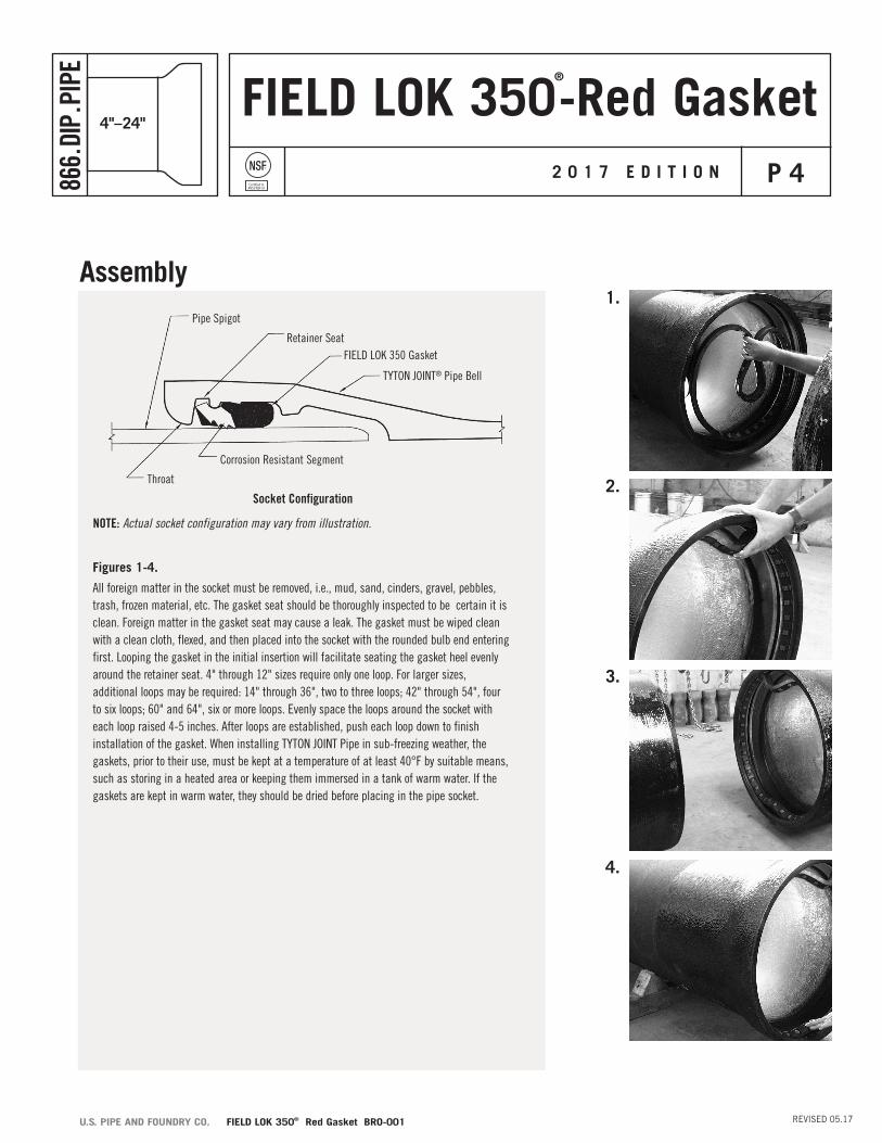
Assembly
Figures 1-4.
All foreign matter in the socket must be removed, i.e., mud, sand, cinders, gravel, pebbles, trash, frozen material, etc. The gasket seat should be thoroughly inspected to be certain it is clean. Foreign matter in the gasket seat may cause a leak. The gasket must be wiped clean with a clean cloth, flexed, and then placed into the socket with the rounded bulb end entering first. Looping the gasket in the initial insertion will facilitate seating the gasket heel evenly around the retainer seat. 4" through 12" sizes require only one loop. For larger sizes, additional loops may be required: 14" through 36", two to three loops; 42" through 54", four to six loops; 60" and 64", six or more loops. Evenly space the loops around the socket with each loop raised 4-5 inches. After loops are established, push each loop down to finish installation of the gasket. When installing TYTON JOINT Pipe in sub-freezing weather, the gaskets, prior to their use, must be kept at a temperature of at least 40°F by suitable means, such as storing in a heated area or keeping them immersed in a tank of warm water. If the gaskets are kept in warm water, they should be dried before placing in the pipe socket.
Pipe Spigot
Retainer SeatFIELD LOK 350 Gasket
TYTON JOINT® Pipe Bell
Corrosion Resistant Segment
Throat
NOTE: Actual socket configuration may vary from illustration.
Socket Configuration
1.
2.
3.
4.

FIELD LOK 350-Red GasketNSF®
Certified toANSI/NSF 61
P 5866.
DIP.
PIPE
REVISED 05.17U.S. PIPE AND FOUNDRY CO. FIELD LOK 350® Red Gasket BRO-001
4"–24"
2 0 1 7 E D I T I O N
®
Figure 5.
Apply a thin film of TYTON JOINT® Lubricant to the exposed surface of the gasket that will come into contact with the entering pipe spigot. In warm, dry weather conditions, the lubricant can dry out, especially when applied to warm or hot pipe, it will be necessary to add a small amount of water to hydrate the lubricant. Only TYTON JOINT Lubricant should be used.
CAUTION: The use of spray-on lubricant is not recommended. Experience has determined that spray-on lubricant may not have sufficient lubricity to allow joint assembly without gasket displacement.
Figure 6.
When pipe is cut in the field, the cut end may be readily conditioned so that it can be used to make up the next joint. The outside of the cut end (or any pipe without a bevel) should be beveled about 1/4" at an angle of about 30 degrees and the leading edge should be rounded. This can be done quite easily with a portable grinder. The operation removes any sharp, rough edges which otherwise might damage the gasket.
Figure 7.
When cut pipe, which have no assembly stripes, are to be assembled, the spigot insertion depth should be marked on the spigot to ensure that the joint is fully assembled. When deflection is required at the joint, the spigot should not be completely homed. Assembly mark locations by size and deflection information is given in Table 2.
Figure 8.
6 to 7 inches of the spigot should be cleaned and a thin coat of TYTON JOINT® Lubricant applied.
Assembly (cont.)
NOTE: Thick Coatings or Tape Wrap — The FIELD LOK 350 Gasket should not be used on pipe and fittings which have thick coatings or tape wrap on the outer diameter of the pipe. In general, if the peen pattern is not visible on the pipe surface, the asphalt coating may be too thick for proper penetration of the teeth of the FIELD LOK 350 Gasket. The thick coating should be removed from the end of the pipe or fitting before assembly. The coating must be no more than 2 mils thick for asphalt coating and 6 mils nominal thickness for 2 part epoxy coating on the plain end of the pipe.
When it is known that field cuts will be made, several lengths can be ordered as “gauged full length”. U.S. Pipe “gauged full length” pipe are marked with a green stripe on the bell face. The ANSI/AWWA C151/A21.51 standard for Ductile Iron pipe requires factory gauging of the spigot end. Accordingly, pipe selected for field cutting should be measured at the location of the intended cut and must be within the tolerances shown in Table 1.
5.
6.
7.
8.
FIELD LOK 350-Red GasketNSF®
Certified toANSI/NSF 61
P 6866.
DIP.
PIPE
REVISED 05.17U.S. PIPE AND FOUNDRY CO. FIELD LOK 350® Red Gasket BRO-001
4"–24"
2 0 1 7 E D I T I O N
®
FeelerGauge
Stainless SteelLocking Segment
FIELD LOK 350® Gasket
9.
10.
11.
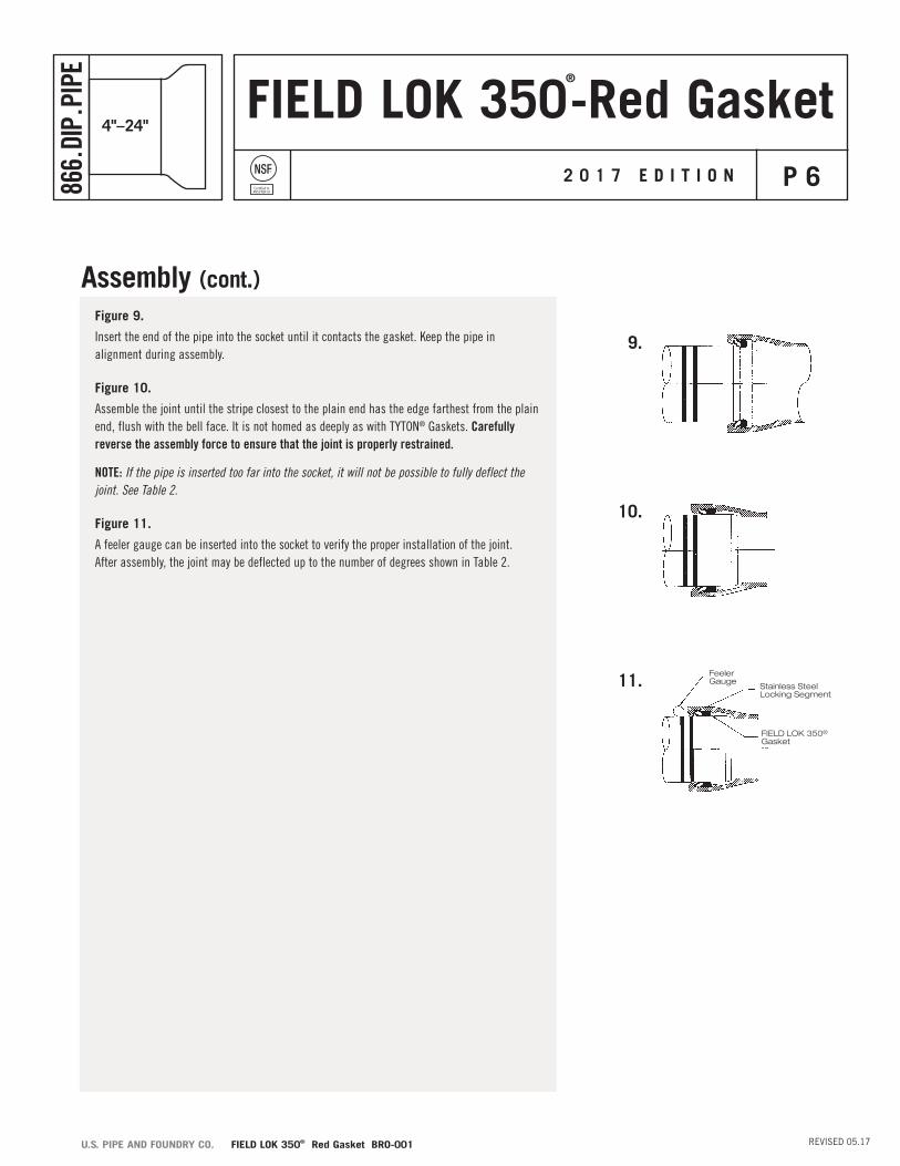
Figure 9.
Insert the end of the pipe into the socket until it contacts the gasket. Keep the pipe in alignment during assembly.
Figure 10.
Assemble the joint until the stripe closest to the plain end has the edge farthest from the plain end, flush with the bell face. It is not homed as deeply as with TYTON® Gaskets. Carefully reverse the assembly force to ensure that the joint is properly restrained.
NOTE: If the pipe is inserted too far into the socket, it will not be possible to fully deflect the joint. See Table 2.
Figure 11.
A feeler gauge can be inserted into the socket to verify the proper installation of the joint. After assembly, the joint may be deflected up to the number of degrees shown in Table 2.
Assembly (cont.)
FIELD LOK 350-Red GasketNSF®
Certified toANSI/NSF 61
P 7866.
DIP.
PIPE
REVISED 05.17U.S. PIPE AND FOUNDRY CO. FIELD LOK 350® Red Gasket BRO-001
4"–24"
2 0 1 7 E D I T I O N
®
The Backhoe Method of AssemblyA backhoe may be used to assemble pipe of all sizes. The plain end of the pipe should be carefully guided by hand into the bell of the previously assembled pipe. The bucket of the backhoe may then be used to push the pipe until fully seated. Keep pipe in alignment to avoid damage to or dislodging of the gasket. A timber header should be used between the pipe and backhoe bucket to avoid damage to the pipe. Avoid “slamming” the pipe home to prevent damage to the lining material inside the bell at the back of the socket.
The Come-A-Long Method of AssemblySome installers may prefer to use come-alongs to assemble TYTON JOINT® Pipe with FIELD LOK 350 Gaskets.
Alternative Assembly Methods
FIELD LOK 350-Red GasketNSF®
Certified toANSI/NSF 61
P 8866.
DIP.
PIPE
REVISED 05.17U.S. PIPE AND FOUNDRY CO. FIELD LOK 350® Red Gasket BRO-001
4"–24"
2 0 1 7 E D I T I O N
®
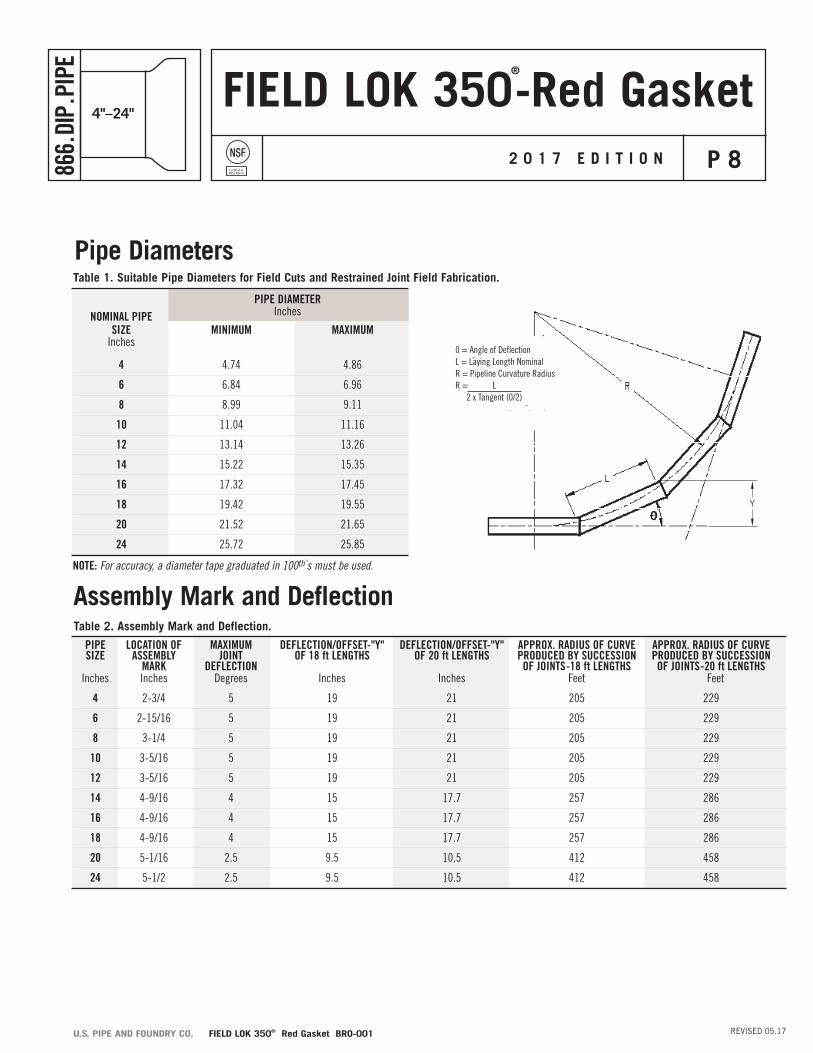
Pipe Diameters
NOMINAL PIPE SIZE MINIMUM MAXIMUM Inches
4 4.74 4.86
6 6.84 6.96
8 8.99 9.11
10 11.04 11.16
12 13.14 13.26
14 15.22 15.35
16 17.32 17.45
18 19.42 19.55
20 21.52 21.65
24 25.72 25.85
Table 1. Suitable Pipe Diameters for Field Cuts and Restrained Joint Field Fabrication.
Table 2. Assembly Mark and Deflection.
Assembly Mark and Deflection
PIPE LOCATION OF MAXIMUM DEFLECTION/OFFSET-"Y" DEFLECTION/OFFSET-"Y" APPROX. RADIUS OF CURVE APPROX. RADIUS OF CURVE SIZE ASSEMBLY JOINT OF 18 ft LENGTHS OF 20 ft LENGTHS PRODUCED BY SUCCESSION PRODUCED BY SUCCESSION MARK DEFLECTION OF JOINTS -18 ft LENGTHS OF JOINTS -20 ft LENGTHS Inches Inches Degrees Inches Inches Feet Feet
4 2-3/4 5 19 21 205 229
6 2-15/16 5 19 21 205 229
8 3-1/4 5 19 21 205 229
10 3-5/16 5 19 21 205 229
12 3-5/16 5 19 21 205 229
14 4-9/16 4 15 17.7 257 286
16 4-9/16 4 15 17.7 257 286
18 4-9/16 4 15 17.7 257 286
20 5-1/16 2.5 9.5 10.5 412 458
24 5-1/2 2.5 9.5 10.5 412 458
PIPE DIAMETER Inches
NOTE: For accuracy, a diameter tape graduated in 100th’s must be used.
0 = Angle of DeflectionL = Laying Length NominalR = Pipeline Curvature RadiusR = L 2 x Tangent (0/2)
FIELD LOK 350-Red GasketNSF®
Certified toANSI/NSF 61
P 9866.
DIP.
PIPE
REVISED 05.17U.S. PIPE AND FOUNDRY CO. FIELD LOK 350® Red Gasket BRO-001
4"–24"
2 0 1 7 E D I T I O N
®
FIELD LOK 350 Gaskets will have a tag attached to them with gasket assembly instructions and a “CAUTION!”notice.
1. Do not use FIELD LOK 350 Gaskets to provide electrical joint conductivity for thawing purposes. Such use may damage the gaskets.
2. Use FIELD LOK 350 Gaskets only in push-on joints which have the trademark TYTON®, TRIM TYTON® or TYTON JOINT®. Use in unapproved joints may result in joint separation.
3. FIELD LOK 350 Gaskets should not be used in above ground installations.
4. Do not use FIELD LOK 350 Gaskets with corroded pipe.
5. U.S. Pipe has not conducted tests with gray iron or plastic piping products and, therefore, cannot recommend or warrant the use of FIELD LOK 350 Gaskets with gray iron (pipe, fittings or valves) or plastic (pipe or fittings).
6. Always make sure that the gasket is properly placed in the socket with the bulb or thickest portion of the gasket being deepest in the socket.
7. Use in casings: pipelines restrained with FIELD LOK 350 Gaskets may be installed in straight casings by pulling, not pushing, the pipe through the casing. Assembly of the joints must be controlled, such as with come-a-longs or cable hoist, to prevent fully “homing” the spigot to the base of the socket to allow for joint deflection and to prevent damaging the cement lining or other special sewer linings.
8. Do not reuse FIELD LOK 350 Gaskets.
9. Do not use FIELD LOK 350 Gaskets with Tyton Plugs or TR FLEX® Joints since it is not possible to take the joint apart once it is assembled.
10. Although disassembly of joints restrained with FIELD LOK 350 Gaskets is possible, the use of TR FLEX Pipe and Fittings is recommended if disassembly of the joints is planned or anticipated.
11. If the maximum joint deflection is necessary, do not push the pipe to the bottom of the socket.
12. For cold weather assemblies, keep the temperature of the FIELD LOK 350 Gaskets above 40º F.
13. Approximately twice as much assembly force may be required to assemble a FIELD LOK 350 Gasket joint as is required for a conventional TYTON® Gasket push-on joint.
14. Concrete Thrust blocking or other means of thrust restraint is not required to be used with FIELD LOK 350 Gaskets when FIELD LOK 350 Gaskets are used in a designed thrust restraint system. The Thrust Restraint Design for Ductile-Iron Pipe published by the Ductile-Iron Pipe Research Association (DIPRA) is one method used to calculate the required length of restraint at a change in direction. This publication is available through your U.S. Pipe representative or at www.dipra.org Pressure Rating: The working pressure rating of the FIELD LOK 350 Gasket Restrained Joint System does not exceed that of the working pressure rating of the pipe in which it is installed.
Special Notes Regarding the use of FIELD LOK 350 Gaskets
FIELD LOK 350-Red GasketNSF®
Certified toANSI/NSF 61
P 10866.
DIP.
PIPE
REVISED 05.17U.S. PIPE AND FOUNDRY CO. FIELD LOK 350® Red Gasket BRO-001
4"–24"
2 0 1 7 E D I T I O N
®
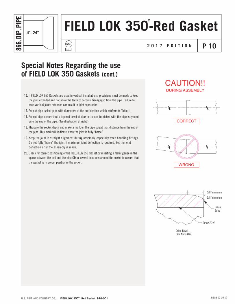
Grind Bevel(See Note #16)
Spigot End
BreakEdge
1/8"minimum
5/8"minimum
Special Notes Regarding the use of FIELD LOK 350 Gaskets (cont.)
15. If FIELD LOK 350 Gaskets are used in vertical installations, provisions must be made to keep the joint extended and not allow the teeth to become disengaged from the pipe. Failure to keep vertical joints extended can result in joint separation.
16. For cut pipe, select pipe with diameters at the cut location which conform to Table 1.
17. For cut pipe, ensure that a tapered bevel similar to the one furnished with the pipe is ground onto the end of the pipe. (See illustration at right.)
18. Measure the socket depth and make a mark on the pipe spigot that distance from the end of the pipe. This mark will indicate when the joint is fully “home”.
19. Keep the joint in straight alignment during assembly, especially when handling fittings. Do not fully “home” the joint if maximum joint deflection is required. Set the joint deflection after the assembly is made.
20. Check for correct positioning of the FIELD LOK 350 Gasket by inserting a feeler gauge in the space between the bell and the pipe OD in several locations around the socket to assure that the gasket is in proper position in the socket.
FIELD LOK 350-Red GasketNSF®
Certified toANSI/NSF 61
P 11866.
DIP.
PIPE
REVISED 05.17U.S. PIPE AND FOUNDRY CO. FIELD LOK 350® Red Gasket BRO-001
4"–24"
2 0 1 7 E D I T I O N
®
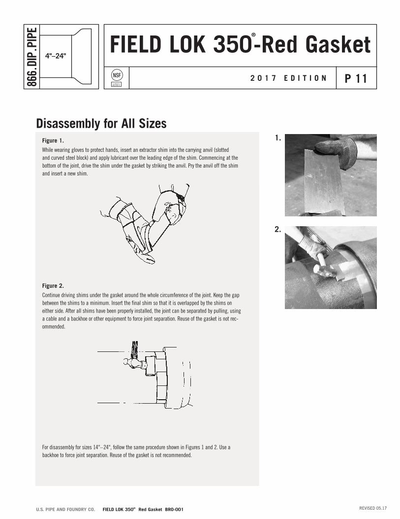
Figure 1.
While wearing gloves to protect hands, insert an extractor shim into the carrying anvil (slotted and curved steel block) and apply lubricant over the leading edge of the shim. Commencing at the bottom of the joint, drive the shim under the gasket by striking the anvil. Pry the anvil off the shim and insert a new shim.
Figure 2.
Continue driving shims under the gasket around the whole circumference of the joint. Keep the gap between the shims to a minimum. Insert the final shim so that it is overlapped by the shims on either side. After all shims have been properly installed, the joint can be separated by pulling, using a cable and a backhoe or other equipment to force joint separation. Reuse of the gasket is not rec-ommended.
For disassembly for sizes 14"–24", follow the same procedure shown in Figures 1 and 2. Use a backhoe to force joint separation. Reuse of the gasket is not recommended.
Disassembly for All Sizes1.
2.
FIELD LOK 350-Red GasketNSF®
Certified toANSI/NSF 61
P 12866.
DIP.
PIPE
REVISED 05.17U.S. PIPE AND FOUNDRY CO. FIELD LOK 350® Red Gasket BRO-001
4"–24"
2 0 1 7 E D I T I O N
®
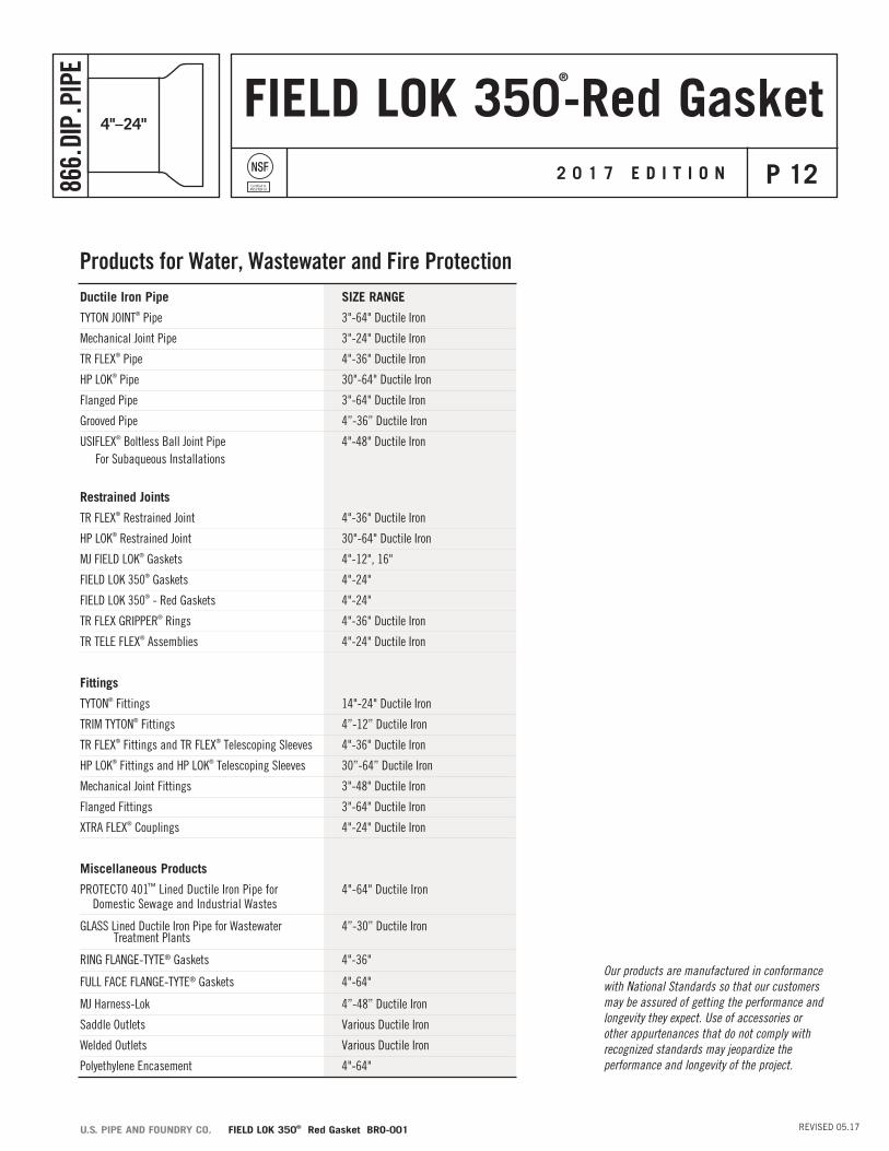
Products for Water, Wastewater and Fire ProtectionDuctile Iron Pipe SIZE RANGE
TYTON JOINT® Pipe 3"-64" Ductile Iron
Mechanical Joint Pipe 3"-24" Ductile Iron
TR FLEX® Pipe 4"-36" Ductile Iron
HP LOK® Pipe 30"-64" Ductile Iron
Flanged Pipe 3"-64" Ductile Iron
Grooved Pipe 4”-36” Ductile Iron
USIFLEX® Boltless Ball Joint Pipe 4"-48" Ductile Iron For Subaqueous Installations
Restrained Joints
TR FLEX® Restrained Joint 4"-36" Ductile Iron
HP LOK® Restrained Joint 30"-64" Ductile Iron
MJ FIELD LOK® Gaskets 4"-12", 16"
FIELD LOK 350® Gaskets 4"-24"
FIELD LOK 350® - Red Gaskets 4"-24"
TR FLEX GRIPPER® Rings 4"-36" Ductile Iron
TR TELE FLEX® Assemblies 4"-24" Ductile Iron
Fittings
TYTON® Fittings 14"-24" Ductile Iron
TRIM TYTON® Fittings 4”-12” Ductile Iron
TR FLEX® Fittings and TR FLEX® Telescoping Sleeves 4"-36" Ductile Iron
HP LOK® Fittings and HP LOK® Telescoping Sleeves 30”-64” Ductile Iron
Mechanical Joint Fittings 3"-48" Ductile Iron
Flanged Fittings 3"-64" Ductile Iron
XTRA FLEX® Couplings 4"-24" Ductile Iron
Miscellaneous Products
PROTECTO 401™ Lined Ductile Iron Pipe for 4"-64" Ductile Iron Domestic Sewage and Industrial Wastes
GLASS Lined Ductile Iron Pipe for Wastewater 4”-30” Ductile Iron Treatment Plants
RING FLANGE-TYTE® Gaskets 4"-36"
FULL FACE FLANGE-TYTE® Gaskets 4"-64"
MJ Harness-Lok 4”-48” Ductile Iron
Saddle Outlets Various Ductile Iron
Welded Outlets Various Ductile Iron
Polyethylene Encasement 4"-64"
Our products are manufactured in conformance with National Standards so that our customers may be assured of getting the performance and longevity they expect. Use of accessories or other appurtenances that do not comply with recognized standards may jeopardize the performance and longevity of the project.
All U.S. Pipe brochures and/or products are subject to change without further notice.
Revised 05-17
TWO CHASE CORPORATE DRIVESUITE 200
BIRMINGHAM, AL 35244
866.DIP.PIPE (866.347.7473)