journal - ijarem
TRANSCRIPT
International
Journal Of Advanced Research in Engineering & Management (IJAREM)
ISSN: 2456-2033 || PP. 71-86
\
| Vol. 03 | Issue 07 | 2017 | 71 |
Development of a hydropneumatic water pressure booster tank
system for water hammer mitigation
Chika Edith Mgbemena1, Chinedum Ogonna Mgbemena
2, Samuel Kika
Ugbebor2, Joseph Oyetola Oyekale
2
1Department of Industrial/Production Engineering, Nnamdi Azikiwe University, Awka, Anambra State, Nigeria.
2Department of Mechanical Engineering, Federal University of Petroleum Resources, Effurun, Delta State,
Nigeria.
Corresponding Author: Chika Edith Mgbemena. Department of Industrial/Production Engineering, Nnamdi
Azikiwe University, Awka, Anambra State, Nigeria. [email protected]
Notations q Pump flow capacity
∆𝐻𝐹𝐹 Pressure drop in fittings or valves
𝐾 Resistance factor for fitting or valve
V Fluid velocity
g Gravitational constant or acceleration due to gravity
𝐶𝐴 Corrosion Allowance
B Pump cut-in pressure
C Pump cut-out pressure
Abstract: In many developed and developing countries alike, installed elevated water storage tanks are
often characterized with pressure losses, thereby impairing the effectiveness of the installations. Also,
accidents and fatalities caused by water hammerare common experience during operational life of such
facilities, a situation that has been of serious concern to experts in this field in recent times. It is believed
that these challenges are mostly associated with design factors and/or design considerations not fully
satisfied. The concept of boosting the pressure of water during a no/low flow shutdown of the pump is
believed to be one major solution to the pressure drop challenge. This concept, when it utilizes air in its
operation to boost water pressure for enhanced delivery, is generally being referred to as hydropneumatic
water pressure booster (HWPB)tank system. HWPBsystems provide pressured water quickly when
needed without the use of a pump. They have received wide acceptance and application recently, in terms
of field applications, as well as in research and development. While HWPB system is already fully
operational in many advanced countries, its developmental trajectory has always pointed downwards in
many developing countries across the globe. Since most water-related problems are mostly common in
Africa and other developing economies, there is obvious need for tailored design and development of
such innovation asHWPB tank system, to augment the existing methods of water distribution for every
locality. The presentresearch article therefore aims to present comprehensive design of a 1.8m3capacity
HWPB tank. Itwas designed to safely boost water pressure to a maximum allowable pressure of 0.90MPa,
suitable for application in most Nigerian communities. The required total tank volume, pump capacity,
pipe size and velocitywere calculated in accordance with American Water Works Association (AWWA)
standard; while the pressure tank shell thickness, head thickness and flange rating were designed in
consonance with the requirement of ASME and API 650. Static structural analysis of the tank was
performed to ascertain its integrity against catastrophic failure. The HWPB tank developed was
implemented in a hostel for students at Federal University of Petroleum Resources, Effurun, Nigeria, to
ascertain its functionality and operability. The results obtained from the Stress analysis of the HWPB tank
showed that the deformation of the tank was within the elastic range, which is below the Yield strength of
the selected design material. It was therefore concluded that the tank would function safely when
operated at the maximum calculated internal pressure of 0.90MPa.
Keywords:Hydropneumatic water pressure booster, tank, stress distribution
International
Journal Of Advanced Research in Engineering & Management (IJAREM)
ISSN: 2456-2033 || PP. 71-86
\
| Vol. 03 | Issue 07 | 2017 | 72 |
D Pre-charge air pressure
ρ Density
ρw Density of water
σys Yield stress
σts Tensile stress
𝜎𝐻 Hoop stress
St Hydrostatic Test Stress
T Temperature
To Operating temperature
Td Design temperature
ɵmt Metal temperature
E Young’s Modulus
Q Quantity of liquid stored
Po Operating pressure
P Maximum Operating Pressure
Ph Hydrostatic Test Pressure
𝑃𝑤Maximum Internal Design Pressure at required thickness
S Maximum Allowable Stress at Design Temperature
Sd Product Design Stress
𝑆𝑝Stress at Maximum Allowable Working Pressure (MAWP) and required thickness
R Shell Inside Radius
L Shell Length
1. Introduction
The elevated tank system for water storage and distribution under pressure has been in existence since
ancient times. The tank is placed on a platform elevated at a height sufficient to pressurize the discharge of
water through gravity to the distribution zone.The elevated platform may be constructed of wood, concrete or
metal (steel), with steel being the most common material for elevated platform construction(―Water tank stands:
what material is best? | Rainharvest.co.za,‖ n.d.). A basic water distribution system is made up of storage tanks,
reservoirs, pipes, pumps, valves, metres, fittings and other hydraulic appurtenances that connects the treatment
plants to consumer taps(Drinking Water Distribution Systems, 2006).
Different types of water distribution and storage systems have been designed to meet different needs
for industrial and domestic purposes(Alberg, 2000; Henderson, 2012). These systems can be easily
differentiated by their physical features like component configuration, type of material used in the construction
and the mode of water distribution: by gravity pressure system, direct pressure system or by pneumatic pressure
system. Pneumatic water pressure booster tank system of water distribution is an improvement of the oldgravity
tank method used in elevated storage tank systems(Peerless Pump Company, 2005). A hydropneumatic tank
contains boththe pressurized air and water. Air is in direct contact with the water and it does not have a bladder.
The compressed air acts as a cushion exerting or absorbing pressure. A hydropneumatic tank servesthree main
roles:to deliver water within a selected pressure range thereby preventing the well pump from continuously
running, to keepthe pump from starting up every time there is a minor call for water from the distribution
system, and tominimize pressure surges (water hammer)(State Department of Health et al., 2011).
The major function of HWPB is to control or boost a limited water supply pressure to a higher or more
uniform value so that a continuous and satisfactory water supply would be available at all plumbing fixtures
within the system. The operating principle of a system which accomplishes this purpose consists of a suitable
booster pump, a hydropneumatic bladder tank and essential control devices such as pressure switch, pressure
gauge, foot valve and a non-return valve, to aid an automatic operation of the system with the least amount of
supervision. The pump is used for supplying the required amount of water into the tank at the proper pressure
while the tank acts as a storage vessel for the proper ratios of water and air within the pressure and levels
maintained by the pressure switch. A HWPB tank is widely used to enhance water flow rate;toserve as a
pressurized water storage tank for industrial and domestic purpose.It also helps to maintain the pump-cycle rate
required to avoid overheating and premature motor failure of the booster pump motor. These pressure tanks are
usually above ground level with supports to hold the weight.

International
Journal Of Advanced Research in Engineering & Management (IJAREM)
ISSN: 2456-2033 || PP. 71-86
\
| Vol. 03 | Issue 07 | 2017 | 73 |
In a study on HWPB, hydropneumatictanks were employed with pipe network models of water
systems, to evaluate the performance of existing water systems and the design of new distribution
facilities(Smith, 2005). In another study,model equations were developed for the dipping tube hydropneumatic
tank in water distribution systems to mitigate the problem of water hammer (Wang et al., 2013a). The use of
hydropneumatic tanks were found to be very effective in limiting the problem of water hammer (Besharat et al.,
2016; Cao et al., 2013; Triki, 2016; Wang et al., 2013b).
While HWPB system is already fully operational in many advanced countries, its developmental
trajectory has always pointed downwards in many developing countries across the globe. Since most water-
related problems are mostly common in Africa and other developing economies, there is need for tailored design
and development of such innovation as HWPB tank system to augment the existing methods of water
distribution for every locality.
In this study, a HWPB tank of 1.8m3 capacityhas been designed, such that it would be able to safely
enhance water pressure to a maximum pressure of 0.9MPa,with negligiblewater hammer effect. The HWPB tank
was designed to satisfy the requirements of the AWWA, ASME, API 650 and other relevant standards and
codes. The HWPB tank designedwasdeployed at the Federal University of Petroleum Resources, Effurun,
Nigeria (FUPRE Students’ hostel) water distribution network,to address the various limiting issues with
elevated tanks. The study area is depicted in Figure 1.
2. Design Details and Material Selection
The design considerations, calculations, fabrication and erection procedures for the HWPB tank are
presented below.
2.1 Design Considerations
The following parameters were considered and calculated using the appropriate formulas and
standards.
Booster pump flow capacity
The pump flow capacity, q [m3/s] was calculated using Hunters method in accordance with AWWA standard
(Bhatia, 2012).
Pipe sizing and flow velocity
Defined by the pump flow capacity q [gpm].
Dynamic pressure losses in fittings and valves
The fittings friction or pressure drop PD is obtained from the relation (Chaurette, 2005).
∆𝐻𝐹𝐹 = 𝐾𝑣2
2𝑔 (1)
Where, ∆𝐻𝐹𝐹 is the pressure drop in fittings or valves, 𝐾is the resistance factor for fitting or valve, V is the fluid
velocity, and g is the gravitational constant.
Pump total head
The pump total head is one of the first steps in pump selection for the design of a pneumatic water
pressure booster tanks. Equation (2) gives the pump total head (Chaurette, 2005).
𝑇𝑜𝑡𝑎𝑙𝑛𝑢𝑚𝑏𝑒𝑟𝑜𝑓𝑓𝑖𝑥𝑡𝑢𝑟𝑒𝑠 × 𝑓𝑎𝑐𝑡𝑜𝑟𝑓𝑟𝑜𝑚𝑡𝑎𝑏𝑙𝑒 2
Total tank volume
The total tank volume can be determined after selection of the pump capacity, tank type and pressureswitch
settings. The total tank volume can be determined by(Wellcare®, 2007):
𝑇𝑜𝑡𝑎𝑙𝑡𝑎𝑛𝑘𝑣𝑜𝑙𝑢𝑚𝑒 = 𝑀𝑖𝑛𝑖𝑚𝑢𝑚𝑑𝑟𝑎𝑤𝑑𝑜𝑤𝑛
𝐷𝑟𝑎𝑤𝑑𝑜𝑤𝑛𝑓𝑎𝑐𝑡𝑜𝑟 (3)
The minimum drawdown is the quantity of water the booster pump can supply to the bladder per minute; the
drawdown factor is the factor of the total tank volume that will provide available water. Wellcare® (2007)
recommends that the tank air pre-charge pressure should be set at 2 psi below the low system pressure or cut-in
pressure to prevent a noticeable drop in pressure at the fixture. The drawdown factor is expressed as:

International
Journal Of Advanced Research in Engineering & Management (IJAREM)
ISSN: 2456-2033 || PP. 71-86
\
| Vol. 03 | Issue 07 | 2017 | 74 |
𝐷𝑟𝑎𝑤𝑑𝑜𝑤𝑛𝑓𝑎𝑐𝑡𝑜𝑟 = 𝐷 + 14.7
𝐵 + 14.7−
𝐷 + 14.7
𝐶 + 14.7 (4)
Where B refers to the pump cut-in pressure, C is the pump cut-out pressure, and D is the pre-charge air pressure.
Design of Tank Head and Shell
Tank shell design method as per [UG-27] ASME section VIII was employed (ASME, 2010b). When
the thickness does not exceed one-half of the inside radius, or P does not exceed 0.385SE, the
following equations apply:
𝑡 =𝑃𝑅
𝑆𝐸 − 0.6𝑃+ 𝐶𝐴𝑜𝑟𝑃 =
𝑆𝐸𝑡
𝑅 + 0.6𝑡 (5)
𝑡 =𝑃𝑅
2𝑆𝐸 + 0.4𝑃𝑜𝑟𝑃 =
2𝑆𝐸𝑡
𝑅 − 0.4𝑡 (6)
Corrosion Allowance
Corrosion allowance (CA) for the head and shell plates was considered to be 1mm due to the severity
ofdegradation on these parts. Although water will not be in direct contact with the internal surface of the tank
since a butyl bladder mechanism will be installed. The added thickness to the shell and head in the course of
design would suffice any effect of corrosion.
2.2 Material Selection
Material selection was done based on the design consideration for the shell, and head plates of the tank.
A516 was selected from the list of ASTM recommended pressure vessel plate material as shown in Table 1.
However, ASTM carbon steel A516 was selected due to its moderate yield strength, moderate cost, low and
moderate operating temperature, environment consideration, resistance to corrosion, dimensional stability and
weldability. ASTM recommends a series of carbon steel plate material which could be considered when
fabricating pressure tanks.
Table 1 Preferred ASTM Specified pressure vessel plate materials
Materials σys
(MPa)
T
(0C)
ρ
(g/cc)
E
(GPa)
Cost
(N/ 4ft×8ft)
ASTM A515 265 100 and above 7.85 160 20,000
ASTM A516 240 10 and above 7.85 200 10,000
ASTM A202 310 100 and above 7.80 200 15,000
Stainless Steel 215 100 and above 8.00 200 25,000
The chemical composition and mechanical properties of ASTM A516 is shown in Table 2.
Table 2 ASTM A516 Chemical composition and mechanical properties
Chemical composition
Element Content
Carbon, C 0.31%
Manganese, Mn 0.85 - 1.2%
Phosphorus, P 0.035%
Sulphur, S 0.040%
International
Journal Of Advanced Research in Engineering & Management (IJAREM)
ISSN: 2456-2033 || PP. 71-86
\
| Vol. 03 | Issue 07 | 2017 | 75 |
Silicon, Si 0.15 - 0.40%
Mechanical Properties
Tensile Strength (MPa) 485 – 620
Yield strength (MPa) 220 – 260
Modulus of Elasticity (GPa) 200
Poisson’s Ratio 0.29
Shear Modulus (GPa) 80
Elongation at Break 17% - 21%
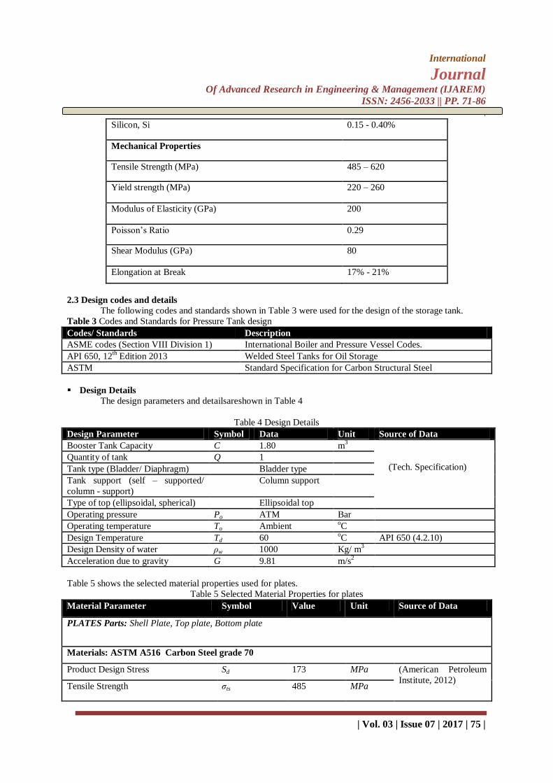
2.3 Design codes and details
The following codes and standards shown in Table 3 were used for the design of the storage tank.
Table 3 Codes and Standards for Pressure Tank design
Codes/ Standards Description
ASME codes (Section VIII Division 1) International Boiler and Pressure Vessel Codes.
API 650, 12th Edition 2013 Welded Steel Tanks for Oil Storage
ASTM Standard Specification for Carbon Structural Steel
Design Details
The design parameters and detailsareshown in Table 4
Table 4 Design Details
Design Parameter Symbol Data Unit Source of Data
Booster Tank Capacity C 1.80 m3
(Tech. Specification) Quantity of tank Q 1
Tank type (Bladder/ Diaphragm) Bladder type
Tank support (self – supported/
column - support)
Column support
Type of top (ellipsoidal, spherical) Ellipsoidal top
Operating pressure Po ATM Bar
Operating temperature To Ambient oC
Design Temperature Td 60 oC API 650 (4.2.10)
Design Density of water ρw 1000 Kg/ m3
Acceleration due to gravity G 9.81 m/s2
Table 5 shows the selected material properties used for plates.
Table 5 Selected Material Properties for plates
Material Parameter Symbol Value Unit Source of Data
PLATES Parts: Shell Plate, Top plate, Bottom plate
Materials: ASTM A516 Carbon Steel grade 70
Product Design Stress Sd 173 MPa (American Petroleum
Institute, 2012) Tensile Strength σts 485 MPa

International
Journal Of Advanced Research in Engineering & Management (IJAREM)
ISSN: 2456-2033 || PP. 71-86
\
| Vol. 03 | Issue 07 | 2017 | 76 |
Hydrostatic Test Stress St 195 MPa
Metal temperature ɵmt 150 °F
Yield Strength σys 240 MPa
Young Modulus EA516 200 GPa
Comment: Carbon Steel A516 was considered due to its high yield strength, low cost, availability in relevant
dimensions and well understood requirements for fabrication and testing. The carbon steel material was also
found to be compatible with the bladder material used.
The capacity of the pump in m3/s (cubic meters per second) is computed with the assumption that:
The time span ofsingle operation of different fixtures are known.
Not all plumbing fixtures were used simultaneously.
Fixtures will require more water supply during peak demand periods such as in mornings andevenings.
The air pressure in the pressure tank should be 13.78 kPa less than the cut-in pressure of the booster pump.
The water reservoir is underground and water level is 4.57metersbelow the booster pump.
A bucket and a water closet flush tank have a water capacity of 0.015 m3.
Only 10 Water closets are used during peak demand period.
The water supply pipe length between each room is 3.05meters long, and contains a Gate valve, Check
valve, Elbow and Tee fitting.
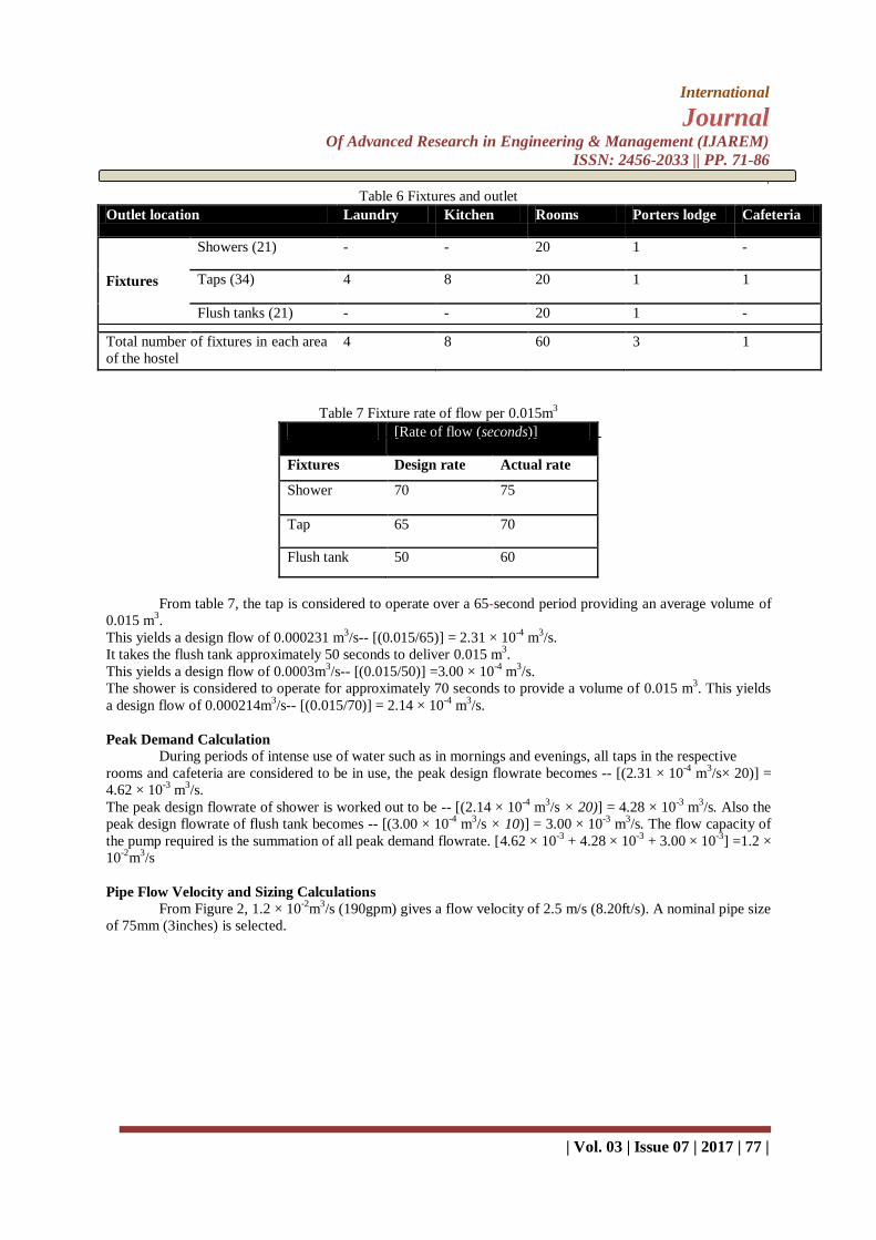
Table 6 shows the various types of plumbing fixtures and appurtenances installed atFederal University
of Petroleum Resources Nigeria, (FUPRE)students’ hostel, and the various plumbing outlet locations, while
Table 7 showsthe fixture rate of flow per 0.015m3. Figure 1 shows the aerial view of the study area.
Figure 1 Aerial view of FUPRE Hostel
International
Journal Of Advanced Research in Engineering & Management (IJAREM)
ISSN: 2456-2033 || PP. 71-86
\
| Vol. 03 | Issue 07 | 2017 | 77 |
Table 6 Fixtures and outlet
Outlet location Laundry Kitchen Rooms Porters lodge Cafeteria
Fixtures
Showers (21) - - 20 1 -
Taps (34) 4 8 20 1 1
Flush tanks (21) - - 20 1 -
Total number of fixtures in each area
of the hostel
4 8 60 3 1
Table 7 Fixture rate of flow per 0.015m3
[Rate of flow (seconds)]
Fixtures Design rate Actual rate
Shower 70 75
Tap 65 70
Flush tank 50 60
From table 7, the tap is considered to operate over a 65-second period providing an average volume of
0.015 m3.
This yields a design flow of 0.000231 m3/s-- [(0.015/65)] = 2.31 × 10
-4 m
3/s.
It takes the flush tank approximately 50 seconds to deliver 0.015 m3.
This yields a design flow of 0.0003m3/s-- [(0.015/50)] =3.00 × 10
-4 m
3/s.
The shower is considered to operate for approximately 70 seconds to provide a volume of 0.015 m3. This yields
a design flow of 0.000214m3/s-- [(0.015/70)] = 2.14 × 10
-4 m
3/s.
Peak Demand Calculation
During periods of intense use of water such as in mornings and evenings, all taps in the respective
rooms and cafeteria are considered to be in use, the peak design flowrate becomes -- [(2.31 × 10⁻⁴
m3/s× 20)] =
4.62 × 10⁻³
m3/s.
The peak design flowrate of shower is worked out to be -- [(2.14 × 10⁻⁴
m3/s × 20)] = 4.28 × 10
-3 m
3/s. Also the
peak design flowrate of flush tank becomes -- [(3.00 × 10⁻⁴
m3/s × 10)] = 3.00 × 10
-3 m
3/s. The flow capacity of
the pump required is the summation of all peak demand flowrate. [4.62 × 10⁻³
+ 4.28 × 10⁻³
+ 3.00 × 10⁻³
] =1.2 ×
10-2
m3/s
Pipe Flow Velocity and Sizing Calculations
From Figure 2, 1.2 × 10⁻²
m3/s (190gpm) gives a flow velocity of 2.5 m/s (8.20ft/s). A nominal pipe size
of 75mm (3inches) is selected.

International
Journal Of Advanced Research in Engineering & Management (IJAREM)
ISSN: 2456-2033 || PP. 71-86
\
| Vol. 03 | Issue 07 | 2017 | 78 |
Figure 2 Graphical depiction of friction loss through PVC pipe (Powers et al., 2007)
Tables 8-9 show the shell design and head plate calculations while Tables 10-11 show the flange
rating design and fixture and appurtenance design
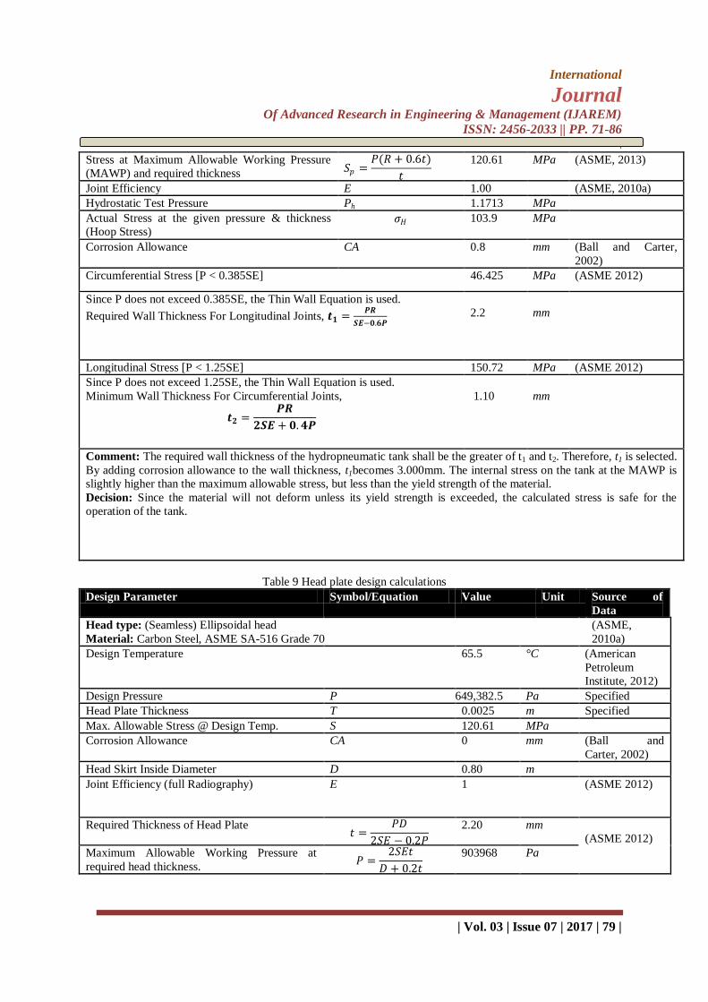
Table 8 Shell design calculations
Design Parameter Symbol/Equation Value Unit Source of Data
Cylindrical Shell Thickness Under Internal Pressure
Material: Carbon Steel, ASME SA-516 Grade 70
(ASME, 2012)
Shell Inside Diameter D 0.80 m
Shell Inside Radius R 0.40 m
Nominal Wall Thickness T 0.0025 m (ASME, 2012)
Shell Length L 1.40 m
Corrosion Allowance CA 0.002 m
Min. Design Metal Temperature -28.8 °C (ASME, 2010a)
Max. Design Temperature 65.5 °C
Max. Operating Pressure P 649,382.5 Pa
Max. Internal Design Pressure @
required thickness. 𝑃𝑤 =
𝑆𝐸𝑡
𝑅 + 0.6𝑡
900,523
Pa
Max. Allowable Stress @ Design Temp. S 120.61 MPa (ASME, 2012)
International
Journal Of Advanced Research in Engineering & Management (IJAREM)
ISSN: 2456-2033 || PP. 71-86
\
| Vol. 03 | Issue 07 | 2017 | 79 |
Stress at Maximum Allowable Working Pressure
(MAWP) and required thickness 𝑆𝑝 =𝑃(𝑅 + 0.6𝑡)
𝑡
120.61 MPa (ASME, 2013)
Joint Efficiency E 1.00 (ASME, 2010a)
Hydrostatic Test Pressure Ph 1.1713 MPa
Actual Stress at the given pressure & thickness
(Hoop Stress) 𝜎𝐻
103.9 MPa
Corrosion Allowance CA 0.8 mm (Ball and Carter,
2002)
Circumferential Stress [P < 0.385SE] 46.425 MPa (ASME 2012)
Since P does not exceed 0.385SE, the Thin Wall Equation is used.
Required Wall Thickness For Longitudinal Joints, 𝒕𝟏 =𝑷𝑹
𝑺𝑬−𝟎.𝟔𝑷
2.2
mm
Longitudinal Stress [P < 1.25SE] 150.72 MPa (ASME 2012)
Since P does not exceed 1.25SE, the Thin Wall Equation is used.
Minimum Wall Thickness For Circumferential Joints,
𝒕𝟐 =𝑷𝑹
𝟐𝑺𝑬 + 𝟎. 𝟒𝑷
1.10
mm
Comment: The required wall thickness of the hydropneumatic tank shall be the greater of t1 and t2. Therefore, t1 is selected.
By adding corrosion allowance to the wall thickness, t1becomes 3.000mm. The internal stress on the tank at the MAWP is
slightly higher than the maximum allowable stress, but less than the yield strength of the material.
Decision: Since the material will not deform unless its yield strength is exceeded, the calculated stress is safe for the
operation of the tank.
Table 9 Head plate design calculations
Design Parameter Symbol/Equation Value Unit Source of
Data
Head type: (Seamless) Ellipsoidal head
Material: Carbon Steel, ASME SA-516 Grade 70
(ASME,
2010a)
Design Temperature 65.5 °C (American
Petroleum
Institute, 2012)
Design Pressure P 649,382.5 Pa Specified
Head Plate Thickness T 0.0025 m Specified
Max. Allowable Stress @ Design Temp. S 120.61 MPa
Corrosion Allowance CA 0 mm (Ball and
Carter, 2002)
Head Skirt Inside Diameter D 0.80 m
Joint Efficiency (full Radiography) E 1 (ASME 2012)
Required Thickness of Head Plate 𝑡 =
𝑃𝐷
2𝑆𝐸 − 0.2𝑃
2.20 mm
(ASME 2012)
Maximum Allowable Working Pressure at
required head thickness. 𝑃 =
2𝑆𝐸𝑡
𝐷 + 0.2𝑡
903968 Pa

International
Journal Of Advanced Research in Engineering & Management (IJAREM)
ISSN: 2456-2033 || PP. 71-86
\
| Vol. 03 | Issue 07 | 2017 | 80 |
Comment: The required thickness of the plate is 2mm. Due to the effect of condensation of the compressed air on the
internal surface of the head plate, a corrosion allowance 0.8mm is added to the required thickness. Hence, the required
thickness becomes 3.000mm
Table 10 Flange Rating design
Design Parameter Symbol/Equation Value Unit Source of Data
Shell and Head Material: Carbon Steel, ASME SA-516 Gr.70
Flange type: Circular Flange
Flange Material: Forged Carbon Steel, ASME SA-105
(ASME, 2013)
Design Temperature T 65.5 °C (American Petroleum
Institute, 2012)
Design Pressure P 799240 Pa
Max. Allowable Stress @
Design Temp.
S 120.61 MPa (ASME 2012)
Material Specification Group
no.
Group 1.1 (ASME, 2013)
Maximum Allowable Design
Pressure
PW 1869946 Pa (ASME, 2013)
Comment: For the Flange rating selection, A105 material was selected in accordance with ASME B16.5. The
material group number for the selected material specification was obtained from Table B4. The intersection of
design temperature with the Flange Class that can accommodate the design Pressure (116psi) will give the
maximum allowable pressure of the flange.
Decision: At 150°F (65.5°C), for Group 1.1 flange material, the Lowest Class that will accommodate a design
pressure of 116 psi (799,240 Pa) is Class 150. At 65.5°C a Class 150 flange of Material Group 1.1 can have a
design pressure up to 18.72bar (1.872MPa). Hence, the maximum allowable design pressure of the flange is
1.87MPa.
Table 11 Fixtures and appurtenances
Fitting Description Quantity Size Location Source of Data
Galvanized Bushing 1 3/8‖ ×1/2‖ At one side of the head (ASTM, 2016)
Pressure gauge 1 0 – 10bar Screwed to the galvanized
bushing
(IS:3624-1987,
1988)
Schrader valve 1 M6 At the Centre of the head
Maintenance Chamber 1 6‖ At one side of the head
(ASME, 2010b) Lifting rings 1 100mm At the Centre of the head
Table 12 shows the hydropneumatic pressure tank design details
Parameter Value
Tank Capacity 2.000m3
Drawdown Capacity 0.72m3
Diameter 0.8 m
Tank Stand 0.3m
Stand base 0.13m
Tank Total Height 1.7m
Maximum System Pressure 9 bar
Maximum water pressure 6.5 bar

International
Journal Of Advanced Research in Engineering & Management (IJAREM)
ISSN: 2456-2033 || PP. 71-86
\
| Vol. 03 | Issue 07 | 2017 | 81 |
Minimum water pressure 3.5 bar
Air precharge pressure 3.36 bar
Tank Shell
Type Vertical
Height of Shell 1.28m
Circumference of tank 2.52m
Plate thickness 3mm
Tank Head
Type Ellipsoidal
Radius of curved edge 0.06m
Lifting ring length 0.12m
Head Plate Thickness 3mm
Maximum Working Pressure 0.65MPa
Maximum Allowable Working Pressure 0.90MPa
Hydraulic Test Pressure 117.13MPa
Minimum Water Design Temperature -28.80C
Maximum Water Design Temperature 65.50C
Materials
Shell and Head
Bladder type (BS 3227:1990)
Flange (Maintenance Chamber)
Pipe (3‖)
Pressure gauge (0 – 10Bar)
Schrader valve
Carbon Steel ASTM A516 Grade 70
Butyl rubber(fixed and replaceable)
Forged Carbon Steel, ASME SA-105
Polyvinyl Chloride (PVC)
IS-3624
Design Standard ASME Section VIII-1, ASTM and API
650
2.4 Tank Weld Details
According to API 650, vertical shell joints of the Pressure tank should be butt-welded with complete
penetration and complete fusion attained by double welding the inside and outside weld surfaces. Horizontal
shell joints shall have complete penetration and complete fusion. Bottom plates shall also be Butt-welded.
2.5 Finite Element Analysis of the Pressure Tank
The analysis of the hydropneumatic pressure booster tank was performed usingSolidWorks 2011. The
following assumptions were made for ease of analysis:
• Analysis will be static structural analysis
• Temperature effect was considered at room temperature
3. Results and Discussion
3.1 Design analysis
The following basic parameters for the pressure tank were determined; the nominal diameter (0.8m),
Shell height (1.28m), Tank height (1.4m), Maximum design temperature, maximum operating pressure with
respect to the given maximum allowable stress of the material from API 650 standard. Thin wall shell was
considered because the design pressure is less than 0.385SE and a corrosion allowance of 0.8 was
considered.The shell thicknesses are adjusted due to hydrostatic load and stability during design, hence
addedthickness would suffice any effect of corrosion. The maximum internal pressure and the stress atdesign
pressure were determined. The calculated internal stress on the tank at the MAWP is slightlyhigher than the
maximum allowable stress, but less than the yield strength of the material, this meansthat the material will not
deform unless its yield strength is exceeded. Therefore, the calculated stressis safe for the operation of the tank.
The required thickness of the head plate was determined as stated in Table 9. Due to the effect of corrosion as a
International
Journal Of Advanced Research in Engineering & Management (IJAREM)
ISSN: 2456-2033 || PP. 71-86
\
| Vol. 03 | Issue 07 | 2017 | 82 |
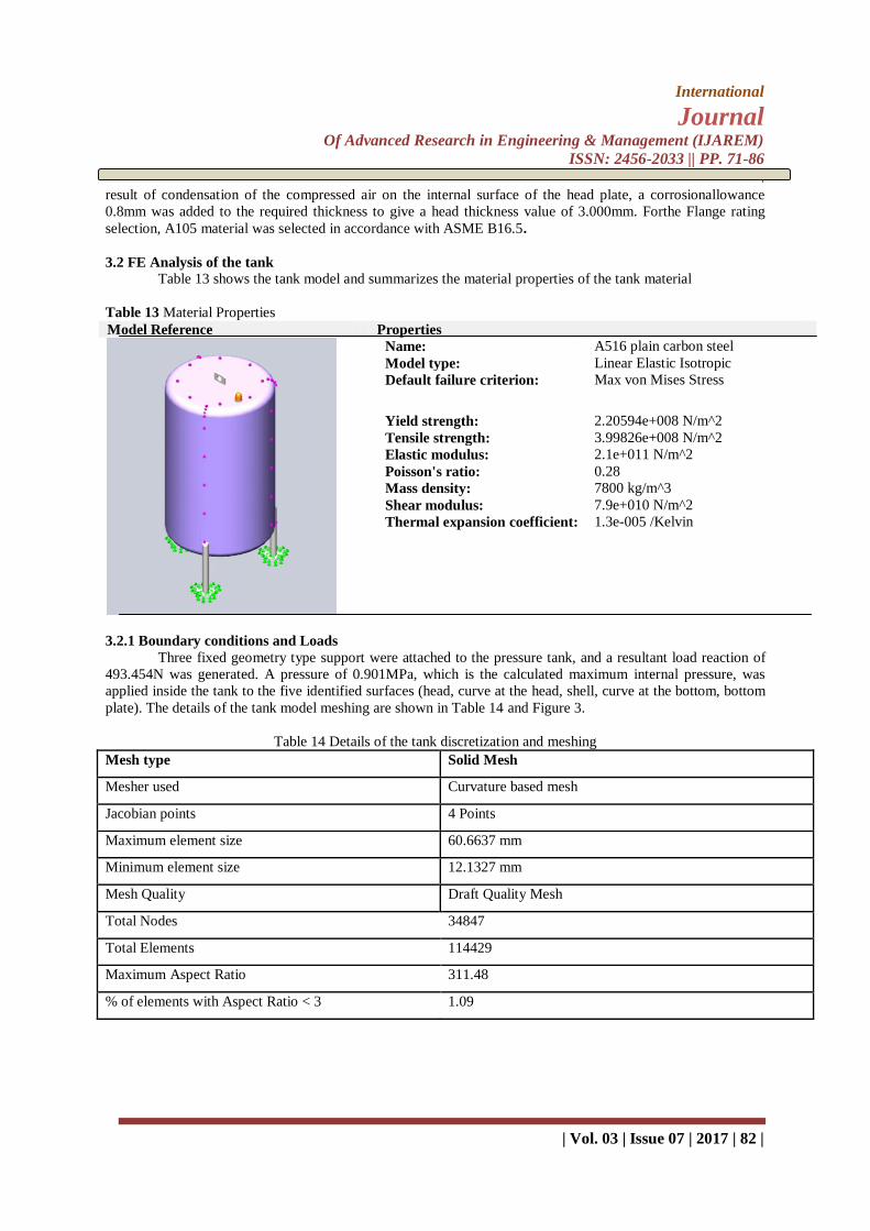
result of condensation of the compressed air on the internal surface of the head plate, a corrosionallowance
0.8mm was added to the required thickness to give a head thickness value of 3.000mm. Forthe Flange rating
selection, A105 material was selected in accordance with ASME B16.5.
3.2 FE Analysis of the tank
Table 13 shows the tank model and summarizes the material properties of the tank material
Table 13 Material Properties
Model Reference Properties
Name: A516 plain carbon steel
Model type: Linear Elastic Isotropic
Default failure criterion: Max von Mises Stress
Yield strength: 2.20594e+008 N/m^2
Tensile strength: 3.99826e+008 N/m^2
Elastic modulus: 2.1e+011 N/m^2
Poisson's ratio: 0.28
Mass density: 7800 kg/m^3
Shear modulus: 7.9e+010 N/m^2
Thermal expansion coefficient: 1.3e-005 /Kelvin
3.2.1 Boundary conditions and Loads
Three fixed geometry type support were attached to the pressure tank, and a resultant load reaction of
493.454N was generated. A pressure of 0.901MPa, which is the calculated maximum internal pressure, was
applied inside the tank to the five identified surfaces (head, curve at the head, shell, curve at the bottom, bottom
plate). The details of the tank model meshing are shown in Table 14 and Figure 3.
Table 14 Details of the tank discretization and meshing
Mesh type Solid Mesh
Mesher used Curvature based mesh
Jacobian points 4 Points
Maximum element size 60.6637 mm
Minimum element size 12.1327 mm
Mesh Quality Draft Quality Mesh
Total Nodes 34847
Total Elements 114429
Maximum Aspect Ratio 311.48
% of elements with Aspect Ratio < 3 1.09

International
Journal Of Advanced Research in Engineering & Management (IJAREM)
ISSN: 2456-2033 || PP. 71-86
\
| Vol. 03 | Issue 07 | 2017 | 83 |
Figure 3 The meshed Tank model
3.2.2 Stress Analysis
The von Mises stress obtained from the FE analysis are shown in figures 4 and 5. The maximum stress
at which the tank will fail is 631.972 MPa. This stress value is higher than both the allowable stress and the
yield strength of the material. The figure also shows that the minimum stress generated as 0.0104 MPa. The
stresses are localized at the head and bottom of the tank, and ranges between 155MPa and 160MPa as seen on
the colour plot.From Table 9 the maximum allowable design stress at the design temperature falls below the
range obtained from the colour plot in Figure 3. Since the yield strength of the selected material is higher than
the stress produced at the localized areas on the head of the tank, the localized stress are considered to be within
the permissible elastic range.
Figure 4 von Mises stress plot of the pressure tank

International
Journal Of Advanced Research in Engineering & Management (IJAREM)
ISSN: 2456-2033 || PP. 71-86
\
| Vol. 03 | Issue 07 | 2017 | 84 |
Figure 5 Section view of stress distribution in the tank
3.2.3 Displacement and Strain Analysis
The displacement plot of the pressure tank subjected to given loading conditions is as shown in figure
6. The maximum deformation obtained is 2.354 mm which is in the centre portion of the head; this is so due to
the reaction of the upward compression of air caused by the bladder. Maximum displacement occurring on the
shell is within the range of 1 ×10-30
mm to 0.231 mm. The displacement allowed is 5 mm; so the design is safe
for displacement. The strain plot of the pressure tank is shown in Figure 7. A maximum strain of 5.14 × 10⁻⁸
was
generated.
The strain generated on the shell is within 5.139 ×10⁻⁸
to 5.858 ×10⁻⁴
. A strain of 1.751 ×10⁻³
was generated at
the head of the tank.
Figure 6 Displacement plot of the pressure tank

International
Journal Of Advanced Research in Engineering & Management (IJAREM)
ISSN: 2456-2033 || PP. 71-86
\
| Vol. 03 | Issue 07 | 2017 | 85 |
Figure 7 Strain distribution of the tank
4. Conclusion The AWWA, ASTM, ASME Section VIII division 1 and API 650 and other relevant standards
weresuccessfully used to design ahydropneumatic water pressure booster tank system. A model of the
hydropneumatic water pressure booster tank system was developed and analysed, usingFinite Element Analysis,
implemented in SolidWorks 2014. Also, static structural analysis was carried out on the pressure tank model
using SolidWorks 2014. The effect of the calculated internal working pressure in the pressure tank was analyzed
and considered as being safe for the operation of the pressure tank,since the deformation of the tank at the
maximum allowable pressure appeared to be within the elastic range, which is below the yield strength of the
selected material. The study has no doubt contributed to the development of hydropneumatic water pressure
booster system in Nigeria, as a case of developing countries.
Acknowledgement The authors wish to acknowledge the efforts of Prof. Akii Ibhadode, the Vice Chancellor, Federal
University of Petroleum Resources, Effurun, Nigeria, in stimulating indigenous research.
References [1]. Alberg, S.C., 2000. PORTABLE WATER TANK AND BOOSTER. US6152707.
[2]. American Petroleum Institute, 2012. API 650:Welded Steel Tanks for Oil Storage.
[3]. ASME, 2013. ASME B16.34-2013 Valves—Flanged,Threaded, and Welding End. New York.
[4]. ASME, 2012. PDHonline Course M398 (3 PDH).
[5]. ASME, 2010a. II Part D Properties (Metric) MATERIALS, ASME Boiler & Pressure Vessel
Committee on Materials. New York.
[6]. ASME, 2010b. B31.1 Power Piping: New York.
[7]. ASTM, 2016. Standard Specification for Castings, Austenitic, for Pressure-Containing Parts 1 (No.
A351/A351M). PA. doi:10.1520/A0351_A0351M-16
[8]. Ball, B.E., Carter, W.J., 2002. CASTI Guidebook to ASME Section VIII Div. 1 - Pressure Vessels
CASTI Guidebook Series -Vol. 4, 3rd ed. CASTI Publishing Inc, Alberta.
[9]. Besharat, M., Tarinejad, R., Ramos, H.M., 2016. The effect of water hammer on a confined air pocket
towards flow energy storage system. J. Water Supply Res. Technol. - AQUA 65, 116–126.
doi:10.2166/aqua.2015.081
[10]. Bhatia, A., 2012. Sizing Plumbing Water Systems Course Content PART I - ESTIMATING WATER
International
Journal Of Advanced Research in Engineering & Management (IJAREM)
ISSN: 2456-2033 || PP. 71-86
\
| Vol. 03 | Issue 07 | 2017 | 86 |
DEMANDS (No. PDH Course M126), PDHonline Course M126 (3PDH).
[11]. Cao, H., Zheng, C., Luo, F., Guo, L., 2013. The Effect of Surge Tanks in the Process of the Protection
towards Water Hammer Fluctuation in Long-Distance Pipelines, in: ICPTT 2013. American Society of
Civil Engineers, Reston, VA, pp. 249–261. doi:10.1061/9780784413142.026
[12]. Chaurette, J., 2005. TUTORIAL CENTRIFUGAL PUMP SYSTEMS.
[13]. Drinking Water Distribution Systems, 2006. . National Academies Press, Washington, D.C.
doi:10.17226/11728
[14]. Henderson, E., 2012. The untold story of water tanks. J. Am. Water Works Assoc. 104, 64–66.
[15]. IS:3624-1987, 1988. Indian Standard Specification for Pressure and Vacuum Gauges (Second
Revision). New Delhi.
[16]. Peerless Pump Company, 2005. TECHNICAL INFORMATION Bulletin, TECHNICAL
INFORMATION Bulletin.
[17]. Powers, J.P., Corwin, A.B., Schmall, P.C., Kaeck, W.E., 2007. Friction Losses for Water Flow
Through a Pipe, in: Construction Dewatering and Groundwater Control: New Methods and
Applications. John Wiley & Sons, Inc., Hoboken, NJ, USA, pp. 597–602.
doi:10.1002/9780470168103.app1
[18]. Smith, R.S., 2005. Simulation of Hydropneumatic Tanks in Computer Pipe Network Models. J.
Hydraul. Eng. 131, 909–911. doi:10.1061/(ASCE)0733-9429(2005)131:10(909)
[19]. State Department of Health, W., Health Division, E., of Drinking Water, O., 2011. Hydropneumatic
Tank Control Systems. Washington D C.
[20]. Triki, A., 2016. Water-hammer control in pressurized-pipe flow using an in-line polymeric short-
section. Acta Mech. 227, 777–793. doi:10.1007/s00707-015-1493-1
[21]. Wang, R.H., Wang, Z.X., Zhang, F., Sun, J.L., Wang, X.X., Luo, J., Yang, H.B., 2013a. Hydraulic
Transient Prevention with Dipping Tube Hydropneumatic Tank. Appl. Mech. Mater. 316–317, 762–
765. doi:10.4028/www.scientific.net/AMM.316-317.762
[22]. Wang, R.H., Wang, Z.X., Zhang, F., Sun, J.L., Wang, X.X., Luo, J., Yang, H.B., 2013b. Hydraulic
Transient Prevention with Dipping Tube Hydropneumatic Tank. Appl. Mech. Mater. 316–317, 762–
765. doi:10.4028/www.scientific.net/AMM.316-317.762
[23]. Water tank stands: what material is best? | Rainharvest.co.za [WWW Document], n.d. URL
http://www.rainharvest.co.za/2014/05/water-tank-stands-what-material-is-best (accessed 5.24.17).
[24]. Wellcare®, 2007. Sizing a Pressure Tank 1–6.