journal of guidance, control, & dynamicsstrapdownassociates.com/blazing gyros for the...
TRANSCRIPT

1
BLAZING GYROS - THE EVOLUTION OF STRAPDOWN INERTIAL NAVIGATION TECHNOLOGY FOR AIRCRAFT
Paul G. Savage
Strapdown Associates, Inc. (SAI)
WBN-14009 www.strapdownasociates.com
May 29, 2015
Originally published in the AIAA Journal Of Guidance, Control, & Dynamics
Volume 36, Number 3, May - June, 2013, Pages 637-655 INTRODUCTION
Inertial navigation is the process of autonomously calculating the position and velocity of a moving vehicle from measurements of angular rotation and linear acceleration provided by vehicle mounted inertial sensors (gyros and accelerometers). The first inertial navigation system (INS) was developed at the MIT Instrumentation Lab (eventually becoming the Charles Stark Draper Laboratory) for ballistic missile guidance [1]. Soon thereafter, the technology was applied to aircraft navigation, with four companies eventually dominating the US aircraft inertial navigation (INS) industry in the 1960s; Honeywell Aerospace and Defense Group with gyro design/manufacturing in Minneapolis, MN and INS design/development/manufacturing in Clearwater, FL; Kearfott in Wayne, NJ; Litton Guidance & Control Division in Woodland Hills, CA, and Delco Electronics Division of General Motors in Milwaukee, WI. Honeywell specialized in high accuracy systems and introduced a new electrostatically suspended gyro (ESG) technology for precision applications. Delco concentrated on transoceanic commercial and military cargo/tanker aircraft applications using the Carousel IV system (a variation of the Titan II ballistic missile inertial guidance set). Litton and Kearfott focused on medium accuracy military tactical aircraft and airborne missile applications. To achieve required gyro accuracy, each of the aforementioned inertial navigation systems was configured with gimbaled platforms to isolate the inertial sensors from aircraft angular rates.
INS advanced development at Litton and Kearfott in the 1960s centered on improving accuracy, reducing size/weight/cost, and improving reliability of gimbaled INS products (important requirements for expanding military aircraft and airborne missile applications). A key contribution was the introduction of dry tuned-rotor-gyro (TRG) technology. Delco focused on reliability improvement for transport applications. Honeywell focused on improved accuracy and reliability of ESG gimbaled systems.
For future cost/reliability/size reduction based in-part on projected advances in computer technology, several companies (most prominently Honeywell), focused a significant portion of company resources on a radically new strapdown approach to inertial navigation; replacing the gimbaled platform with a computerized analytical equivalent, and mounting ("strapping") the inertial sensors directly to the user vehicle. Based on technical books, journals, internet archives,

2
discussions with past colleagues, but mostly from my direct experience and personal records, this article describes the curious and sometimes convoluted path by which the Honeywell strapdown program eventually led to development of the ring laser gyro (RLG) strapdown INS, and conversion from gimbaled to strapdown technology throughout the airborne inertial navigation industry.
For technical background, the article first discusses the concept of inertial navigation using gimbaled versus strapdown system implementations. Angular rotation sensors (gyros), the key instruments in inertial systems, are briefly described and compared for the strapdown approaches considered along the way. The Honeywell GG1300 RLG is described in more detail, the first RLG to meet aircraft strapdown INS accuracy and reliability requirements. Most of the article focuses on the interrelationships and testing of four Honeywell strapdown inertial systems developed in the early through mid 1970s; ATIGS (Advanced Tactical Inertial Guidance System) and LINS (Laser Inertial Navigation System) using the GG1300; RLGN (Ring Laser Gyro Navigator) and its derivative Laser IRS (Inertial Reference System) prototype using a new smaller size Honeywell GG1342 RLG, the latter known at Honeywell as the 7x7 strapdown system. Flight testing of the four Honeywell systems is described; ATIGS by the US Navy's Naval Weapons Center (NWC), LINS by the US Air Force Central Inertial Guidance Test Facility (CIGTF) at Holloman Air Force Base, RLGN by the US Navy's Naval Air Development Center (NADC), and the 757/767 Laser IRS prototype by the Boeing Airplane Company. The proposal process for the new Boeing 757/767 commercial airplane strapdown IRS is also discussed that, with Laser IRS prototype flight test results, led to the selection of Honeywell for the multi-year 757/767 IRS large scale procurement contract, the first for both aircraft strapdown inertial systems and for ring laser gyros. The article concludes with an epilogue of how the Honeywell and Boeing programs soon led to the general conversion from gimbaled to strapdown system technology throughout the entire aircraft inertial navigation industry.
ACRONYMS AFAL - US Air Force Avionics Laboratory, Wright Patterson Air Force Base, Dayton, OH ATIGS - Advanced Tactical Inertial Guidance System CEP - Circular Error Probable (Radius of a circle containing 50% of horizontal radial position
error samples).
CIGTF - US Air Force Central Inertial Guidance Test Facility, Holloman Air Force Base, Alamogordo, NM.
F3 - Form-Fit-Function standardized US Air Force interface specification for INS interchangeability between different suppliers.
INS - Inertial Navigation System with position, velocity, attitude, heading, etc. outputs. In commercial application parlance, also includes guidance steering outputs based on an input waypoint defined flight profile).
IRS - Inertial Reference System (In commercial application parlance, a strapdown INS with position, velocity, attitude, heading, etc. outputs but without guidance steering outputs).
IRU- Inertial Reference Unit (an INS in general) ISA - Inertial Sensor Assembly LASER - Light Amplification by the Stimulated Emission of Radiation

3
LINS - Laser Inertial Navigation System MIT - Massachusetts Institute of Technology MICRON - Micro Navigator NADC - US Naval Air Development Center, Warminster, PA NWC - US Naval Weapons Center, China Lake, CA RIG - Rate Integrating Gyro RLG - Ring Laser Gyro RLGN - Ring Laser Gyro Navigator TRG - Tuned Rotor Gyro ZLG - Zero-Lock Laser Gyro ENGINEERING UNIT NOTATION
arc-sec - Arc second, a unit of angular measurement (60 in one degree) deg - Degrees deg/rt-hr - Degrees per square root of hour fps - Feet per second hr - Hour micron - 0.000001 meters milli-g - 0.001 gs (1 g = 32.2 feet per second per second) min - Minute (of time) nmph - Nautical miles per hour GIMBALED VERSUS STRAPDOWN SYSTEM IMPLEMENTATION APPROACHES
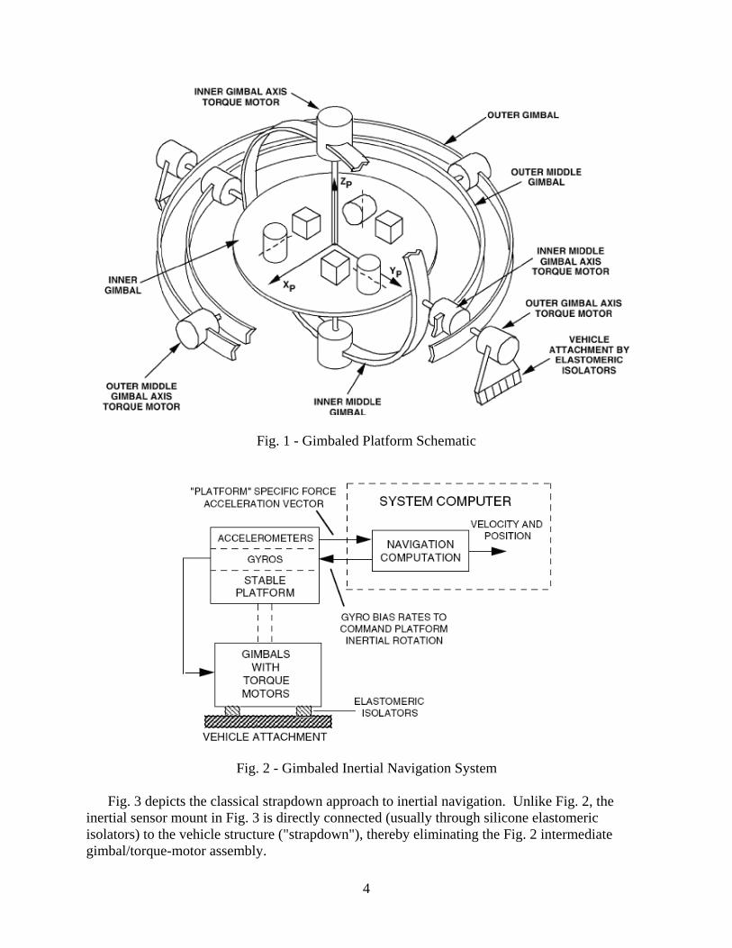
Inertial sensors in a gimbaled inertial navigation system (INS) are orthogonally mounted to a common base ("platform") surrounded by concentric gimbals, interconnected to the platform and each other through ball-bearing shafts (depicted schematically in Fig. 1, the cylinders representing gyros, cubes accelerometers, input axes dashed). Non-rotation of the Fig. 1 sensor platform is actively controlled by torque motors mounted on the gimbal shafts, driven by gyro output measurements of platform rotation. Four-gimbal platforms (Fig. 1) were typically used in aircraft applications for operation at any vehicle angular orientation while maintaining the three inner gimbal shafts near perpendicularity (the optimum orientation for minimum gimbal torque-motor size/power requirements under dynamic angular maneuvering).
Fig. 2 depicts the interfaces between the gimbaled platform and the INS navigation
computer. Platform accelerometer outputs in Fig. 2 (vector components along "platform" axes) are processed in the INS computer to calculate velocity and position. Feedbacks from the navigation computer bias the platform gyros (when allowable for the gyro configuration), commanding the platform to follow prescribed small angular rotation rates; e.g., to maintain a locally-vertical platform orientation relative to the earth in the presence of earth's rotation rate and aircraft translational motion over the earth.
4
Fig. 1 - Gimbaled Platform Schematic
Fig. 2 - Gimbaled Inertial Navigation System
Fig. 3 depicts the classical strapdown approach to inertial navigation. Unlike Fig. 2, the inertial sensor mount in Fig. 3 is directly connected (usually through silicone elastomeric isolators) to the vehicle structure ("strapdown"), thereby eliminating the Fig. 2 intermediate gimbal/torque-motor assembly.

5
Fig. 3 - Rate-Gyro Based Strapdown Inertial Navigation System With minor differences, the navigation computations in Fig. 3 are the same as for the
gimbaled INS configuration of Fig. 2. The basic difference is that the specific force acceleration components provided directly from platform accelerometers in Fig. 2 to the Navigation Computations block, are calculated in Fig. 3 with a vector-transformation operation performed in the system computer. This analytically converts the strapdown accelerometer outputs to the values that would be measured from accelerometers mounted on a Fig. 2 gimbaled platform. The second input to the Vector Transformation block in Fig. 3 is the angular orientation (attitude) of the gyro/accelerometer strapdown mount relative to the equivalent Fig. 2 gyro stabilized platform. The attitude data is calculated by high-speed digital integration operations on strapdown rate-gyro inputs. The feedback gyro biasing operation in Fig.1 for commanding platform rotation rates is also present in Fig. 3, but as part of the attitude computational process so that computed attitude outputs become referenced to Fig. 2 stable "platform axes".
Prior to engaging the inertial navigation function, the initial angular orientation of the Fig. 2 platform (or Fig. 3 computed attitude) must be established during "initial alignment" operations. Under quasi-stationary conditions, this is a self-alignment function in which the physical gimbaled platform (or strapdown computed attitude) is controlled to a locally level orientation, based on accelerometer measurements in Fig. 2 (or transformed acceleration measurements in Fig. 3). Simultaneously, accelerometer heading relative to true north is ascertained from gyro controlled platform accelerometer rates in Fig. 2 (or transformed acceleration rates in Fig. 3) in response to earth's rotation rate, based on the fundamental characteristic that the horizontal component of earth rate points north.
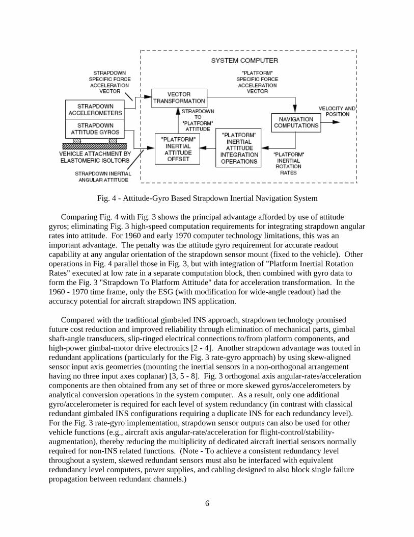
An alternative to the Fig. 3 Rate-Gyro strapdown approach is to use attitude gyros whose
output represents the angular orientation relative to non-rotating inertial space, of the gyro case (hence, the sensor mount to which the gyros are attached). The concept is depicted in Fig. 4.
6
Fig. 4 - Attitude-Gyro Based Strapdown Inertial Navigation System
Comparing Fig. 4 with Fig. 3 shows the principal advantage afforded by use of attitude gyros; eliminating Fig. 3 high-speed computation requirements for integrating strapdown angular rates into attitude. For 1960 and early 1970 computer technology limitations, this was an important advantage. The penalty was the attitude gyro requirement for accurate readout capability at any angular orientation of the strapdown sensor mount (fixed to the vehicle). Other operations in Fig. 4 parallel those in Fig. 3, but with integration of "Platform Inertial Rotation Rates" executed at low rate in a separate computation block, then combined with gyro data to form the Fig. 3 "Strapdown To Platform Attitude" data for acceleration transformation. In the 1960 - 1970 time frame, only the ESG (with modification for wide-angle readout) had the accuracy potential for aircraft strapdown INS application.
Compared with the traditional gimbaled INS approach, strapdown technology promised
future cost reduction and improved reliability through elimination of mechanical parts, gimbal shaft-angle transducers, slip-ringed electrical connections to/from platform components, and high-power gimbal-motor drive electronics [2 - 4]. Another strapdown advantage was touted in redundant applications (particularly for the Fig. 3 rate-gyro approach) by using skew-aligned sensor input axis geometries (mounting the inertial sensors in a non-orthogonal arrangement having no three input axes coplanar) [3, 5 - 8]. Fig. 3 orthogonal axis angular-rates/acceleration components are then obtained from any set of three or more skewed gyros/accelerometers by analytical conversion operations in the system computer. As a result, only one additional gyro/accelerometer is required for each level of system redundancy (in contrast with classical redundant gimbaled INS configurations requiring a duplicate INS for each redundancy level). For the Fig. 3 rate-gyro implementation, strapdown sensor outputs can also be used for other vehicle functions (e.g., aircraft axis angular-rate/acceleration for flight-control/stability-augmentation), thereby reducing the multiplicity of dedicated aircraft inertial sensors normally required for non-INS related functions. (Note - To achieve a consistent redundancy level throughout a system, skewed redundant sensors must also be interfaced with equivalent redundancy level computers, power supplies, and cabling designed to also block single failure propagation between redundant channels.)

7
Before strapdown technology could be considered viable, two major technological advances were required to achieve accuracy levels already attained in gimbaled INS high-volume production; 1) Computer advances to handle new rate-gyro strapdown INS throughput requirements, but most importantly, 2) Never-yet achieved gyro accuracies in a non-gimbaled strapdown dynamic rate environment.
The gimbaled platform in an INS exists for two basic reasons; reducing gyro error (as noted previously) induced by high input angular rates, and to create a stable mount for the accelerometers at a known angular orientation relative to the earth (for earth based position/velocity determination) [9]. By eliminating the stabilized platform, performance requirements for strapdown gyros dramatically increase in scale factor accuracy and sensor-to-sensor alignment for reduced error build-up under attitude changes. A more subtle requirement for aircraft systems is the need for long-term stability of critical inertial sensor performance parameters due to the lack of built-in rotation test equipment (used to measure and compensate inertial sensor performance parameters in a test facility). In a gimbaled INS, rotation calibration can be provided by the gimbal assembly during a special test mode. (For the Delco Carousel gimbaled system, the stable platform is used as a base for mounting a synchronously controlled rotating "table" that houses the horizontal sensors. By continuously rotating the table relative to the stabilized platform at 1 revolution/minute, horizontal accelerometer and gyro biases become averaged, effectively canceling their impact on position/velocity error build-up.) Additionally, normal self-alignment operations prior to navigation mode engagement, implicitly compensate critical sensor errors in a gimbaled INS. During self-alignment, all inertial navigation systems develop platform tilt and heading errors that cancel horizontal accelerometer and east gyro bias. For gimbaled systems, the cancellation remains after navigation mode entry because the sensor platform remains at its self-alignment orientation under subsequent vehicle maneuvering. In contrast, strapdown sensors rotate with the vehicle during navigation, altering their orientation from the alignment attitude (the worst case being a 180 deg heading rotation following initial alignment, effectively doubling the impact of the sensor errors).
To meet the strapdown performance challenge, major design changes had to be incorporated
in conventional angular-momentum based gyros, and a new angular rate sensor was introduced, the ring laser gyro, based on the relativistic properties of light [10]. (The term "gyro" is now commonly used for all angular rate sensing inertial instruments. It derives from "gyroscope", the term originally used for angular rate sensing based on the gyroscopic angular-momentum properties of rotating mass.)
CONVENTIONAL STRAPDOWN GYRO DEVELOPMENT
The distinguishing characteristic between angular-momentum based gyro configurations is the method used to contain the spinning rotor without inducing error from spurious torques on the rotor assembly. Angular-momentum gyros considered during the 1960s for strapdown application were the single-degree-of-freedom floated rate integrating gyro (RIG), the two-axis dynamically compensated dry tuned rotor gyro (TRG), and the electrostatically suspended gyro (ESG) [11 - 13, 14 Chapts 7 - 9, 15 Chapt 4]. The RIG (Fig. 5) supports the rotor assembly by the buoyancy of surrounding viscous fluid. The TRG (Fig. 6) supports the rotor by flexure pivots connected through an intermediate gimbal to the spin-motor shaft. Pivot-flexure spring-

8
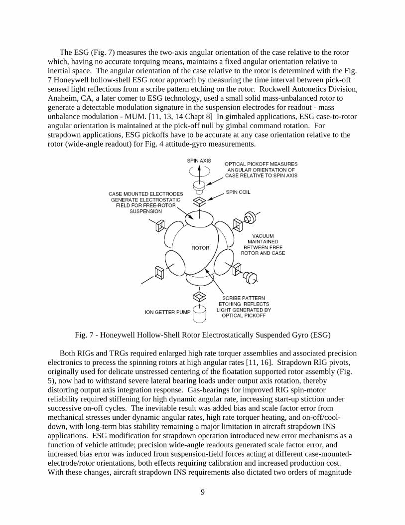
torques on the rotor developed under off-null operation, are thereby compensated by dynamic motion of the spinning gimbal. The two axis ESG (Fig. 7) supports the free-rotor with an electrostatic field applied by case-mounted electrodes.
The RIG (Fig. 5) measures the integrated difference between input axis angular rate and
applied bias rate, the latter provided by an electrical torquer. The TRG (Fig. 6) measures the two-axis angular orientation between the gyro case and rotor. The TRG also contains a torquer assembly for intentionally precessing the spinning rotor axis relative to inertial space. To meet the strapdown gyro performance challenge, "closed-loop" TRG and RIG configurations had to be developed in which electrical input to the torquers are provided in feedback fashion to maintain pickoff output null. The torquer input command thereby becomes proportional to gyro case angular rate, and the strapdown rate-gyro output in Fig. 3.
Fig. 5 - Single-Degree-Of-Freedom Floated Rate Integrating Gyro (RIG)
Fig. 6 - Two-Axis Dry Tuned Rotor Gyro (TRG)
9
The ESG (Fig. 7) measures the two-axis angular orientation of the case relative to the rotor which, having no accurate torquing means, maintains a fixed angular orientation relative to inertial space. The angular orientation of the case relative to the rotor is determined with the Fig. 7 Honeywell hollow-shell ESG rotor approach by measuring the time interval between pick-off sensed light reflections from a scribe pattern etching on the rotor. Rockwell Autonetics Division, Anaheim, CA, a later comer to ESG technology, used a small solid mass-unbalanced rotor to generate a detectable modulation signature in the suspension electrodes for readout - mass unbalance modulation - MUM. [11, 13, 14 Chapt 8] In gimbaled applications, ESG case-to-rotor angular orientation is maintained at the pick-off null by gimbal command rotation. For strapdown applications, ESG pickoffs have to be accurate at any case orientation relative to the rotor (wide-angle readout) for Fig. 4 attitude-gyro measurements.
Fig. 7 - Honeywell Hollow-Shell Rotor Electrostatically Suspended Gyro (ESG)
Both RIGs and TRGs required enlarged high rate torquer assemblies and associated precision electronics to precess the spinning rotors at high angular rates [11, 16]. Strapdown RIG pivots, originally used for delicate unstressed centering of the floatation supported rotor assembly (Fig. 5), now had to withstand severe lateral bearing loads under output axis rotation, thereby distorting output axis integration response. Gas-bearings for improved RIG spin-motor reliability required stiffening for high dynamic angular rate, increasing start-up stiction under successive on-off cycles. The inevitable result was added bias and scale factor error from mechanical stresses under dynamic angular rates, high rate torquer heating, and on-off/cool-down, with long-term bias stability remaining a major limitation in aircraft strapdown INS applications. ESG modification for strapdown operation introduced new error mechanisms as a function of vehicle attitude; precision wide-angle readouts generated scale factor error, and increased bias error was induced from suspension-field forces acting at different case-mounted-electrode/rotor orientations, both effects requiring calibration and increased production cost. With these changes, aircraft strapdown INS requirements also dictated two orders of magnitude
10
improvement in RIG/TRG torquer-loop scale-factor accuracy (compared to gimbaled system requirements), and 2 arc-sec ESG readout accuracy for arbitrary rotor/case attitude.
By the end of the 1960s, strapdown conventional gyros were incapable of meeting general aircraft strapdown INS requirements without performance specification relief or limiting usage to application areas where reduced INS accuracy was acceptable (e.g., operation with inertial aids to mitigate navigational error buildup or limiting strapdown technology to lower angular rate applications). Additionally, as with gimbaled system conventional gyros, strapdown versions required active temperature control (with heaters) to stabilize thermally sensitive performance parameters at compensation-calibrated values. The associated warm-up requirement precluded a desirable faster INS "reaction time", the time from system turn-on to entry into the navigation mode (including platform initial north alignment determination). Ironically, accelerometer thermally sensitive bias trending during heading alignment was actually the warm-up time determining factor. For conventional gyros and accelerometers mounted in close proximity, gyro heating becomes a dominant accelerometer thermal input driver, requiring accelerometer temperature control (and warm-up) for heated gyro compatibility.
RING LASER GYRO DEVELOPMENT
To directly meet the Fig. 3 strapdown rate-gyro challenge from a different perspective, the ring laser gyro (RLG) was introduced in 1963. Unlike traditional angular-momentum gyros whose operation is based on the Newtonian inertial properties of rotating mass, the operating principle for the RLG is based on the relativistic properties of optical standing waves generated by oppositely directed laser beams contained in a closed optical path [11, 12, 17, 18, 14 Chapt 13, 15 Chapt 8].
Fig. 8 depicts the basic operating elements in a ring laser gyro; a closed optical cavity containing two independent beams, each of single frequency light. The beams travel continuously between the reflecting surfaces of the cavity in a closed optical path; one in the clockwise direction, the other counter clockwise, each occupying the same physical space. The light beams are sustained by the lasing action of a helium-neon gas discharge within the optical cavity. The reflecting surfaces are dielectric mirrors designed to selectively reflect the frequency associated with the particular helium-neon transition being used. The counter-rotating beams combine into a standing wave of light that remains inertially fixed as the gyro cavity rotates. A small fraction of each beam escapes the cavity, one reflected through a corner prism, both recombined on photodiode readout detectors. The corner prism is designed to produce a small angle between the recombining beams, thereby creating an optical interference fringe pattern on the photodiodes, each fringe equivalent to a magnified image of the standing wave within the gyro. As the cavity rotates, the fringes traverse the diodes, each fringe corresponding to half the laser wavelength λ for the equivalent angular rotation of the gyro (λ / D radians), where D is the average gyro width (e.g., 2 arc sec of gyro rotation per fringe passage). Photodiode readout logic generates digital output pulses for each fringe quarter-wave passage. Two diodes are used, separated from each other by one quarter of a photodiode-sensed fringe so that resulting diode sinusoidal outputs are 90 deg phase separated. Comparison between diode outputs determines the direction of rotation, positive or negative, depending on whether one diode output is leading or lagging the other.

11
Fig. 8 - Ring Laser Gyro Operating Elements Laser stands for Light Amplification by the Stimulated Emission of Radiation. In an RLG,
the emission process is provided by the helium/neon gas discharge that generates light waves at a discrete atomic transition wavelength when impacted by photons of the same wavelength. For lasing to occur, the RLG mirrors must reflect the emitted light around the closed beam path so that it returns in phase with itself. The beam intensity will then be amplified into resonance until the light emitted ("gain") balances all cavity losses, which then also maximizes beam power. The gain is set by the current magnitude applied to the gas discharge. To satisfy the return-in-phase condition for lasing, the beam path length must be controlled to an integral multiple of discrete lengths corresponding to the optical wavelength of the helium/neon discharge. This is achieved implicitly in the RLG by mirror adjustment to a position for peak beam power. Beam power is measured by a photodiode power detector attached to one of the mirror substrates (Fig. 8). Piezoelectric transducers attached to the outer mirror substrates (Fig. 8) provide the means for actively controlling mirror position, enabling minute adjustments by an electrically applied voltage. The control voltage is generated in closed-loop fashion to sustain maximum output from the power detector. In addition to enabling lasing, the path-length-control process also produces two very important angular rate sensing operational benefits; 1) Stabilization of RLG performance parameters, and 2) Elimination of path length changes from gyro block thermal expansion.
The RLG concept bypassed many of the conventional gyro design issues. Piezoelectric transducer path-length control eliminated the principle source of thermal error sensitivity without requiring direct temperature control. This important characteristic eliminated the warm-up time penalty experienced with conventional gimbaled inertial systems. Stable high scale factor accuracy, the critical performance parameter for strapdown applications, was an inherent quality,

12
independent of bias producing mechanisms. Simple wide-angle readouts could be used with minimum impact on accuracy (because 360 deg laser signal detector scaling corresponds to arc-sec actual gyro input axis rotation). However, the RLG has a unique "lock-in" error mechanism of its own that cannot be eliminated, and had to be circumvented before RLGs could be considered for high accuracy INS application [19].
RLG lock-in is caused by imperfections in the laser reflecting mirrors and optical elements
placed in the beam path that introduce clockwise/counterclockwise beam energy coupling. Beam coupling tends to force the standing wave to follow the cavity rotation (losing its non-rotating inertial property), and producing a "dead-zone" in gyro output at low input rate (e.g., 0.03 deg/sec, depending on mirror quality). The general solution is to artificially bias the gyro input to avoid dwelling in the lock-in region. RLG design activities in the 1960s centered on competing methods for overcoming lock-in, the principle groups involved being Sperry Gyroscope Division of Sperry Rand, Great Neck, NY; Hamilton Standard Division of United Technologies, Windsor Locks, CN; and Honeywell Aerospace and Defense Group, Minneapolis, MN.
Sperry used a modular RLG design approach in which the helium/neon laser sustaining
plasma was contained in gain tubes inserted in the optical beam path, with reflecting mirrors for beam circulation mounted externally [20 - 22, 14 Chapt 13]. Separating the plasma from direct mirror contact eliminated the potential for long-term mirror dielectric coating degradation. Biasing was achieved by applying a cyclic saturating magnetic field to a ferromagnetic coating deposited on the reflecting mirror substrates, enabling magnetically controlled path length shifts (the equivalent of input bias) through the transfer Kerr effect ("magnetic mirror" biasing). The penalty was added bias error from the magnetic mirrors and beam interactions with the gain tube windows. Problems were compounded by ferromagnetic coating absorption of laser beam energy, requiring additional gain to sustain lasing operation, thus amplifying bias errors. Increased gain was acceptable for 1.15 micron helium-neon wavelength Sperry RLG technology, but ultimately limited performance in the 1970s from incompatibility with the more accurate 0.63 micron laser wavelength eventually used by competing groups. (Silicon photodiodes used in RLGs, provide a much stronger response to a 0.63 compared to a 1.15 micron laser beam. This allows 0.63 micron RLGs to operate at reduced gain, thereby reducing gain induced error mechanisms. However, 0.63 micron units are also less tolerant of gain increase without generating unwanted optical resonance modes within the lasing cavity ("multi-moding"). Thus, increased gain could not be used to recover beam energy loss from gain tube inserts and magnetic mirrors. Before finally discontinuing RLG design work in the 1970s, Sperry began investigating garnet magnetic mirror coatings (including "doping" to compensate thermally sensitive bias errors) for reduced laser energy absorption.
Hamilton Standard's DILAG (differential-laser-gyro) approach [11, 12, 23 - 25, 14 Chapt 13, 15 Chapt 8] to RLG lock-in circumvention used a "four-beam" design whereby two sets of superimposed clockwise/counterclockwise laser beams were created , one set right-circularly-polarized (RCP), the other left-circular-polarization (LCP) (as opposed to the plane-polarized clockwise/counterclockwise two-beam configurations of Sperry and Honeywell). The helium/neon gain media was contained directly within the lasing cavity, enclosed by the reflecting mirror substrates. The boundary condition to sustain circular polarization was created by a quartz-crystal insert in the beam path. Biasing for lock-in circumvention was achieved with

13
a magnetically excited glass insert. Through the Faraday effect, the applied magnetic field altered the effective path length of each beam across the glass insert, biasing the RCP and LCP beams out of lock-in. The basic principal for the concept is that true input rate generates the opposite response from each beam set, but that error producing mechanisms in the beam path (from quartz-crystal and glass inserts, plus applied and natural magnetic field bias) produce the same effect. By subtracting the RCP and LCP signals, the true input rate is generated while canceling the error mechanisms in the differencing process. Problems with DILAG were that complete error cancellation did not occur (even theoretically) between the RCP and LCP beams, and additional bias errors were generated by beam interactions with the glass and quartz-crystal inserts. (Note - Under a research program initiated by Raytheon in 1972, a 4 - beam "Multioscillator" RLG configuration was developed using a closed out-of-plane beam path to create circular polarization [26], thus eliminating the need for a quartz-crystal insert and its associated bias error mechanisms).
Honeywell used the Fig. 9 monolithic design approach in which the lasing plasma was enclosed by the mirrors within a closed optical cavity, free of optical material inserts (with associated error mechanisms and potential higher cost) in the laser beam path [11, 12, 17, 18, 14 Chapt 13, 15 Chapt 8]. Eliminating inserts (and associated beam energy loss) provided the
Fig. 9 - Honeywell Ring Laser Gyro Block Assembly
additional benefit of allowing operation at low gain, hence, easier transitioning in the later 1960s from 1.15 to the much more accurate 0.63 micron laser wavelength. High-rate biasing for lock-in circumvention is accomplished by mechanically oscillating the laser block about its input axis at high frequency to minimize dwell time through the lock-in region. Dither motion is generated using a piezoelectric driven rotary flexure suspension (Fig. 9) attached to the lasing block ("dither motor"). The penalty is generation of residual random error in the gyro output ("random walk on attitude") at each passage through the lock-in region (twice per dither cycle). To
14
minimize random walk, lock-in still had to be controlled to low levels by careful mirror design and manufacturing processes (with associated production costs). Selecting mechanical dither lock-in circumvention was an emotionally charged issue because of its seeming contradiction to Honeywell's RLG claim of "no moving parts" for higher reliability (compared to gimbal/motor-drives and gyro-rotor spin-motors in a conventional INS). Of more practical concern, however, were two major reliability problems that severely limited laser gyro life. 1) Susceptibility of "soft-coat" mirror technology to degradation from direct contact of the lasing-plasma with the dielectric- mirror coatings, and 2) Laser-cavity/electrode epoxy-seal leakage and out-gassing that contaminated the lasing cavity. (Onset of the leakage/out-gassing problem was measurable by color in the helium/neon gas discharge; a reddish glow being normal, blue indicating a forthcoming failure. One engineer commented that a pair of rose-colored glasses was needed for emotional survival on a laser gyro program).
By 1971, the required aircraft strapdown INS gyro capability was not in sight for either of the
Sperry, Hamilton Standard, or Honeywell RLG design approaches.
STRAPDOWN COMPUTER ADVANCES
Unlike the strapdown gyro design issues, evolution of required strapdown computer capabilities proceeded as a natural evolution of low-cost computer technology in the 1960s with introduction of digital large-scale integrated circuits (LSICs). Associated strapdown software computational algorithms were developed in parallel for compatibility with available computer memory-size and processor-throughput limitations.
In the early 1960s, general-purpose computers for stapdown application were as large and power consuming as the gimbaled platforms they were to replace. For compatibility with early computer throughput limitations, two competing approaches were pursued for the critical strapdown analytic platform attitude computation; high-order low-speed algorithms implemented by software in the strapdown general-purpose computer [27], and first order high-speed algorithms for DDA (digital differential analyzer) implementation with special purpose digital electronics within the strapdown computer [2]. The former had accuracy limitations through the inability to accurately measure high frequency multi-axis vibratory motion; the latter had cost penalties from added DDA electronics.
The concept of two-speed attitude updating was originated in 1966 [28] as a means to achieve high speed algorithm accuracy within the throughput limitations of existing general purpose computers. The method was to divide attitude updating operations into two parts, a low-speed higher-order algorithm to handle the bulk of the computations, a high-speed algorithm processed in parallel to handle the remaining small amount of computations, then summing the two at attitude update times. The result had the accuracy equivalent of a complete high-speed algorithm but within general-purpose computer throughput/memory limitations. The methodology was not recognized for several years, appearing again in 1969 based on independent work by Jordan and Bortz at NASA-Cambridge and MIT [29, 30]. Two-speed updating has since formed the basis for general strapdown computation algorithm design [31 - 35], with ever-increasing throughput/memory computer advances used to optimize the high-speed portion in higher order form for greater accuracy under vibration and dynamic sensor error [36 - 41].
15
RESTRUCTURING AT HONEYWELL
During the late 1960s and early 1970s, Litton, Kearfott, and Delco solidified their dominance in military airborne medium accuracy gimbaled INS production; Delco for C-141, C-5B, KC-135 aircraft; Kearfott for F-105, A-7D/E, F-16 aircraft and the AGM-69 Short-Range-Attack-Missile (SRAM); Litton for RF-4B/C/E, F-14 aircraft, the AGM-86 Air-Launched-Cruise-Missile (ALCM), and the BGM-109 Tomahawk ship-launched cruise missile. Honeywell continued its dominance in precision gimbaled INS classified applications, acquiring a US Air Force development contract for the GEANS (Gimbaled ESG Aircraft System) for strategic bomber application (applied to the B-1, F-111A and B-52 aircraft) [13]. By 1970, Honeywell strapdown INS development investments had made no inroads into the airborne medium accuracy inertial navigation market, and business planning activities began to consider a potential organizational restructuring for the future.
Before 1970, charter responsibilities between the Honeywell Florida and Minneapolis Divisions were predominantly technology oriented (e.g., inertial navigation systems and general purpose aerospace computers in Florida, aircraft flight/fire control and booster-launch/space attitude/control systems in Minneapolis). With evolving digital technology, aerospace transitioning to digital processing began to create overlap between the Florida and Minneapolis business areas, a notable example being digital attitude referencing using strapdown sensors. This was a technology area under development in Florida for the strapdown INS program and in Minneapolis for space-booster/satellite attitude referencing. To clarify Divisional responsibilities, a major reorganization took place in which charters were restructured based on application rather than technology areas. The result was that boost-launch, space, and missile programs became a Florida group responsibility (requiring movement of several existing programs from Minneapolis to Florida), aircraft applications became a Minneapolis group responsibility (as it had generally been in the past), an exception being that all precision gimbaled ESG applications would remain in Florida. The charter for aircraft medium accuracy strapdown INS development thereby became a new responsibility of the Minneapolis group, and funding was authorized in 1971 for an exploratory study examining whether further Honeywell investment was warranted in this new Minneapolis business area. During the transition of boost-launch/space programs from Minneapolis to Florida, I elected to remain in Minneapolis to conduct the study, and eventually (hopefully) lead a new medium accuracy strapdown aircraft INS program in Minneapolis.
The exploratory study recommended continuing Honeywell investment based on the (usual) projection of strapdown INS cost reductions from low cost LSIC based computer technology (then a reality) and by replacing inertial sensors used for other aircraft functions (e.g., autopilot) with strapdown INS sensor outputs. To eliminate inertial sensor duplication in redundant applications (e.g., INS on transoceanic commercial aircraft and providing inertial sensor outputs for non-INS related redundant aircraft functions), skewed sensor redundancy was promoted as a means for reducing the number of required strapdown sensors [3]. As a solution to the aircraft strapdown gyro long-term accuracy/stability requirement, the study recommended using conventional spinning-wheel strapdown RIG technology with spin-motor reversal applied during normal initial alignment operations (to separate gyro bias error from input earth rate, thereby compensating bias error, and eliminating a significant performance deficiency in earlier Honeywell strapdown INS programs). The conventional gyro baseline was a conservative
16
approach based on Honeywell long-term experience in the design and manufacture of high accuracy RIGs.
Honeywell Management approved continuing the Minneapolis program into the next
developmental phases, but under specific guidelines based on previous Honeywell INS marketing experience: "go slow, monitor the market", "make sure that internal INS interfaces are compatible with eventual transitioning to RLG technology" (when current reliability/performance issues would be resolved), and to avoid head-on competitions with high-volume INS production leaders Delco, Kearfott and Litton (the so-called "back-door marketing approach").
Having been the system project leader on one of the earlier programs with serious blue RLG problems (discussed previously), I was skeptical that laser gyros would ever be compatible with aircraft INS requirements. Nevertheless, believing (probably naively) in our recommended conventional gyro approach, we proceeded accordingly, assuring that sensor/computer interfaces were compatible with either RLG or strapdown RIG interfaces (an easily accomplished task). In sequential steps, the Minneapolis strapdown INS program first developed a spin-motor reversible RIG (a redesign of the Honeywell high accuracy GG8001 ball-bearing spin-motor production gimbaled platform gyro with a large torquer), then the gyro electrical rebalance loops, the analog-to-pulse converter for an analog rebalanced strapdown accelerometer (a to-be-determined model most likely supplied by a non-Honeywell manufacturer due to Honeywell's lack of an affordable strapdown accelerometer at that time), the strapdown navigation computer using the existing Honeywell LSIC-based 301 multi-processor card and an external SEMS-8 magnetic core programmable memory for software development, with strapdown algorithms based on the new two-speed computation approach. In 1974 the stage was set for build of the strapdown inertial sensor assembly (ISA), the final step to complete the system.
THE ADVENT OF LINS
In the early 1970s, 0.63 micron wavelength helium-neon hard-coat dielectric mirror technology was developed for conventional linear laser application and applied by Honeywell in late 1973 to RLGs. Almost simultaneously, Honeywell solved its RLG "metal-to-glass" seal leakage/out-gassing problems by replacing epoxy seals with a metalized solder (allowing dissimilar thermal expansion between metal electrodes and the laser block through seal compliance without epoxy-like micro-cracking). The new seal/coating technologies were cast into the Honeywell GG1300 RLG [42], Fig. 10.
The GG1300 changes from soft to hard coat mirrors and from epoxy to metalized electrode
seals solved Honeywell RLG reliability/life-time problems, and also stabilized key performance parameters. Previous concerns were eliminated for soft coat mirror deterioration from laser beam impingement, stabilizing lock-in (and random walk) at the as-built value. Previous cavity contamination buildup from epoxy seal leakage and out- gassing was eliminated, enabling realization of an outstanding long-term gyro bias stability. Fig. 11 is a sample of RLG bias stability achieved on one of the early GG1300 units over a two-year test period without calibration. Each data point represents a 4.5 hour bias measurement (cumulative output over 4.5 hours divided by 4.5) from gyro turn-on following at least 3 hours of off-time. All data taken is

17
shown in Fig. 11 (i.e., no selective editing). Also shown in Fig. 11 are ± 0.01 deg/hr 1-sigma boundaries representative of aircraft INS performance requirements to meet standard 1 nm/hr CEP (50 % radial error probability) navigational accuracy. Measurements taken on several GG1300s at that time [43, 44] demonstrated random walk accuracy in the 0.003 - 0.008 deg/rt-hr performance range, an important parameter directly impacting system self-alignment time.
Fig. 10 - Honeywell GG1300 Ring Laser Gyro (With 6 Inch Ruler)
Fig. 11 - Original GG1300 Bias Stability Test Data

18
Based on GG1300 test results, the US Naval Weapons Center (NWC), a long supporter of RLG technology development, awarded a contract to Honeywell Florida for design/build of ATIGS (Advanced Tactical Inertial Guidance System), an advanced tactical missile INS for flight-test demonstration against a 0.1 deg/hr gyro bias accuracy requirement. The system (Fig. 12) utilized 3 GG1300 RLGs, 3 Sundstrand QA-1000 quartz pendulum accelerometers, a Delco Magic computer, and associated sensor/system electronics.
Fig. 12 - NWC/Honeywell ATIGS ATIGS flight-testing at NWC began in 1974, the unit mounted in an A-7 Navy fighter
aircraft wing-pod. Performance easily met accuracy goals, demonstrating navigational accuracies in the 5-10 nmph CEP performance range. NWC began to believe that RLG accuracy was approaching 1-3 nmph CEP aircraft INS requirements. Unfortunately, the flight test program was marred with an unforeseen difficulty exacerbated by the ATIGS system/test configuration; use of the 200 watt Delco Magic programmable computer for strapdown inertial computations (an available state-of-the-art device at ATIGS program onset), mounting of the gyros to an aluminum structure that housed the computer (Fig. 12), mounting of the system to the A-7 test aircraft in a wing-pod exposed to ambient temperature, and the unexpected presence of unusual signals on GG1300 RLG output lines. The signals proved to be thermally induced error transients of most peculiar shape and particularly troublesome size (Fig. 13) [45]. The unexpected finding appeared to be in conflict with previous Honeywell claims of "no temperature sensitivity" as an important attribute of RLGs compared to conventional gyros.
The peculiar RLG response characteristic in Fig 13 was uncovered during thermal chamber
tests on a GG1300 at NWC. Following several days of confirmation tests and a series of telephone calls with Honeywell, a high level technical meeting was scheduled in Minneapolis where NWC presented their test results. Upon viewing the data presented, Honeywell engineers agreed that NWC's findings represented a real gyro error effect, and began to focus on the

19
Fig. 13 - Original Honeywell GG1300 Temperature Sensitivity Measurement
GG1300 design configuration, suggesting likely causes for the rogue transient. Identified solutions were to design and package next generation RLGs for thermal symmetry about a critical axis (thereby minimizing externally generated thermal gradients across the gyro lasing block), and to have the gyros mounted within a system to minimize gyro temperature change rate. Unfortunately, ATIGS gyro mountings around the 200 Watt Delco computer introduced significant and lengthy thermal transients into the gyros during computer warm-up, with the GG1300 unsymmetrical thermal packaging arrangement aggravating the problem (Fig. 10). To further complicate matters, the ATIGS wing pod mount on the NWC A-7 test aircraft introduced thermal transients from ambient temperature change with altitude. From a positive standpoint, however, the new findings also suggested that with future RLG packaging improvements, GG1300 technology-based strapdown systems would have a good chance of meeting military aircraft INS accuracy requirements.
Timing of the RLG performance breakthroughs almost exactly coincided with the planned start date for design/build of the strapdown ISA for the Honeywell Minneapolis strapdown system program. Based on the RLG test results, the planned use of conventional momentum-based gyros was abandoned and the decision was made to use GG1300 ring laser gyros in the ISA for LINS (Laser Inertial Navigation System, the acronym selected for the Honeywell Minneapolis aircraft strapdown INS). Since future LINS testing was presumed to be within a pressurized aircraft, it was reasoned that the sudden advent of RLG temperature sensitivity would only be minimally excited during system performance evaluation. For assurance, a gyro characterization study was initiated in Minneapolis as part of LINS ISA design activities, seeking potential methods to compensate residual thermally sensitive GG1300 bias error.
PROVING RLG STRAPDOWN INS TECHNOLOGY READINESS FOR US MILITARY AIRCRAFT
As a definitive demonstration of RLG readiness for aircraft INS application, it was
recognized that a formalized flight test was required to achieve Honeywell's ultimate goal; US government sponsorship (and investment) in a new aircraft RLG INS development program, ultimately leading to full-scale production. However, two programmatic issues had to be reconciled before a meaningful flight test program could be arranged; 1) Lack of readily available government funding for new INS development, and 2) Prior US Air Force selection of

20
the Rockwell Autonetics MICRON (Micro Navigator) ESG strapdown system as the next generation tactical military aircraft INS [46]. (Autonetics had resolved the ESG wide-angle readout problem to the Air Force's satisfaction using their small solid mass-unbalanced rotor MUM approach.) The MICRON program was then entering the Advanced Development Model (ADM) flight test phase. The Air Force had previously budgeted $25 M for MICRON full-scale production development, pending successful ADM flight testing at Holloman Air Force Base.
Through outstanding field work, a resourceful Washington DC Honeywell Sales Group representative briefed an enthusiastic Air Force colonel in the US Defense Department Pentagon of RLG advantages, GG1300 test results, and Honeywell's strapdown INS programs, suggesting that the Air Force might possibly consider changing from ESG to RLG technology for the next generation US military INS. As a direct result, limited funds were made available for government sponsorship of a Honeywell RLG INS demonstration flight test in April, 1975 at CIGTF (Central Inertial Guidance Test Facility), Holloman Air Force Base, Alamogordo, NM on the NC-141A CIGTF test aircraft. The accuracy goal for the test was set at 1 to 3 nmph CEP. A decision was then required by Honeywell as to which system should be tested; the NWC/Honeywell-Florida ATIGS advanced missile system, or the Honeywell Minneapolis LINS aircraft system, the latter not yet having a sensor assembly built for system integration testing, but with the hope of circumventing ATIGS performance limitations.
LINS versus ATIGS flight test system selection was to be made by the Honeywell Strategic Planning Group in Washington DC during an emotionally charged meeting between Honeywell Florida, Honeywell Minneapolis, NWC responsible for US Navy aircraft weapons system integration (the INS being a major component), and NADC responsible for US Navy aircraft INS development. (NADC had sponsored several Honeywell RLG earlier development/test programs) I had personal concerns regarding the meeting outcome because I realized that if the Honeywell-Florida ATIGS was selected as the test article, an inevitable result (assuming reasonable performance) could be transfer of the medium accuracy aircraft INS charter back to Honeywell Florida, and termination of the Honeywell Minneapolis LINS program. Lengthy technical presentations were given at the Washington meeting describing the ATIGS and LINS configurations, the LINS presentation by myself, stressing LINS sensor assembly packaging that would minimize thermally sensitive errors (and being careful not to criticize the Navy sponsored ATIGS). When the presentations were completed, all anxiously awaited the decision of the responsible local Honeywell Vice President - Which system should fly, ATIGS or LINS ? The answer: Both, ATIGS at NWC under recommended extended A-7 testing, and LINS at Holloman on the C-141. I breathed a sigh of relief.
JUMPING HURDLES DURING FLIGHT TEST PREPARATION
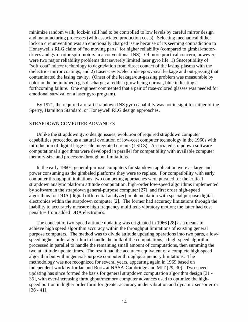
Six months remained before the C-141 flight test for ISA final design/build, LINS integration, and test, when several unexpected problems arose that had to be resolved prior to Holloman delivery in April. A fundamental problem at that time period was long lead-time for parts procurement, a key one needed for LINS being the ISA sensor mounting base, a huge aluminum casting to which the sensors, sensor electronics and cover were mounted within a standard ARINC Long-Tall ATR packaging envelope (Fig. 14). (Note - The ISA casting was designed to mount four RLGs, the fourth not visible in Fig. 14, on the bottom of the chassis. The
21
Fig. 14 - Honeywell Minneapolis Laser Inertial Navigation System (LINS) Inertial Sensor Assembly (Cover Removed)
skew aligned RLG in Fig 14 was included for potential skewed redundancy experiments. For the Holloman tests, the skewed RLG was replaced with an empty RLG case, the skewed RLG used as a spare.). A Honeywell Florida marketing manager predicted that we would never get the casting in time for the flight test. Due to an enthusiastic presentation by our mechanical design engineer Bill Schwartz to a local foundry near the Honeywell Minneapolis plant, the LINS casting was delivered within one month ("They've got the casting !" proclaimed the Florida manager).
Of greater importance, however, was the lead-time required for accelerometer procurement.
Having only limited experience in strapdown digital attitude and tactical missile inertial guidance systems, I had neglected to account for higher accelerometer accuracy requirements in an aircraft INS compared to our planned LINS procurement of available tactical missile grade Sundstrand Data Control (of Redmond, WA) QA-1000 quartz-pendulum accelerometers used in ATIGS (1 milli-g long-term bias stability instruments compared with 50 μg for 1 nmph CEP INS accuracy following calibration, in this case, over the flight test period). The potential risk in our plan was informally identified to me by Jack Shaw of the Seattle Boeing aircraft group who was then leading a feasibility program to assess the readiness of strapdown technology within an integrated all-digital flight-management system architecture for the next generation Boeing commercial aircraft (designated the 7x7 - later to become the 757 and 767). This presented not only a lead-time problem, but a fundamental sourcing question of whether an acceptable accelerometer could be obtained anywhere in the limited time remaining (companies with aircraft INS accuracy accelerometers were in the gimbaled INS business and unlikely to assist a potential new strapdown INS competitor). Jack suggested we consider the Systron Donner 4841 fluid-damped pendulous accelerometer. The 4841 had self-contained electronics and its analog

22
output was fully compatible with the LINS analog-to-pulse computer interface previously developed for the planned QA-1000 accelerometer. Systron Donner 4841s and Teledyne TRGs had been used in an experimental strapdown system built under Jack's Boeing program with encouraging results, both sensors operating heaterless to minimize system reaction time, an important element in establishing feasibility for commercial aircraft operations [47]. Heaterless operation was new for TRGs that had been normally operated with temperature controls in high accuracy gimbaled systems. Strapdown application required novel thermal compensation techniques for rotor-mounted torquer-magnet heating effects under high rotation rates. However, heaterless operation was standard for the 4841, then in production for the US Army Lance MGM-52 mobile surface-to-surface missile. The 4841 used a unique diamond-jewel onto steel press-fit interface for the accelerometer pendulum flexure pivot that was electrically "buzzed" at turn-on. The buzzing action produced press-fit slippage into a stress-free flexure orientation, eliminating residual error torques on the pendulum.
A rush meeting was arranged in Minneapolis with Systron Donner marketing manager Brad Sage and 4841 accelerometer design engineer Phil Flanner. Following a description of the GG1300 based LINS strapdown system, the fast approaching Holloman demonstration test date was discussed and Honeywell's future hopes for RLG strapdown INS technology presented, particularly regarding the forecasted new Boeing 7x7 and its promise for high volume production. Based on Honeywell's presentation, Systron Donner volunteered to quickly ship four 4841 accelerometers from the Lance production line to Honeywell (3 for the ISA plus one spare). With the accelerometers and casting now in hand, work was finally initiated on LINS ISA build and integration testing.
Another unexpected problem arose during system integration that had to be solved before Holloman flight testing would be permitted - The need for a non-interruptible (battery backed-up) power supply to interface 400 Hz 3-phase C-141 generator power with LINS. This is a standard requirement for all aircraft INS equipment to avoid system computer information loss during potential aircraft power transients. However, to conserve investment costs, design of such a device (not a simple task) was planned for future production development, not for the LINS engineering demonstration system. The fallacy in our plan was that a non-interruptible power supply was required even for the flight demonstration test. Prior to main engine start-up, the INS under test must perform initial self-alignment under power from the aircraft auxiliary power unit (APU); alignment must then be maintained through transition from APU to primary generator power following main engine start-up, with an accompanying power outage transient. An additional requirement at Holloman was to continue inertial navigation monitoring in the C-141 for 42 minutes following flight test completion, main engine shutdown, and retransfer of power to the APU. Fortunately, a local Minneapolis branch of Gulton Industries was able to quickly respond to our procurement request, providing a flyable custom "brass-board" backup power supply built around a huge battery capable of operating LINS for more than 1 hour with no input power.
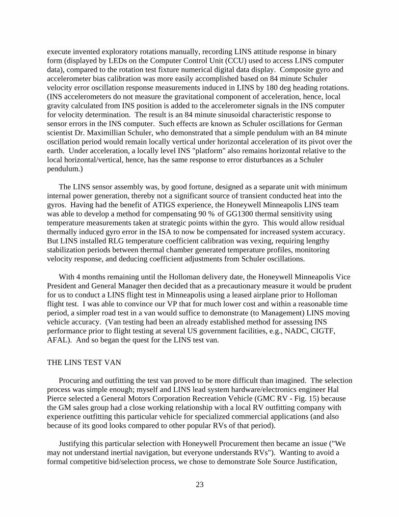
Being inexperienced with inertial navigation systems, we in Minneapolis had to learn/improvise methods for measuring and calibrating the multitude of strapdown sensor/system compensation coefficients in LINS software during final system integration. Sensor misalignment calibration was most difficult because the only precision rotation fixture then available in Honeywell Minneapolis had inoperable servo control motors, hence, we had to
23
execute invented exploratory rotations manually, recording LINS attitude response in binary form (displayed by LEDs on the Computer Control Unit (CCU) used to access LINS computer data), compared to the rotation test fixture numerical digital data display. Composite gyro and accelerometer bias calibration was more easily accomplished based on 84 minute Schuler velocity error oscillation response measurements induced in LINS by 180 deg heading rotations. (INS accelerometers do not measure the gravitational component of acceleration, hence, local gravity calculated from INS position is added to the accelerometer signals in the INS computer for velocity determination. The result is an 84 minute sinusoidal characteristic response to sensor errors in the INS computer. Such effects are known as Schuler oscillations for German scientist Dr. Maximillian Schuler, who demonstrated that a simple pendulum with an 84 minute oscillation period would remain locally vertical under horizontal acceleration of its pivot over the earth. Under acceleration, a locally level INS "platform" also remains horizontal relative to the local horizontal/vertical, hence, has the same response to error disturbances as a Schuler pendulum.)
The LINS sensor assembly was, by good fortune, designed as a separate unit with minimum internal power generation, thereby not a significant source of transient conducted heat into the gyros. Having had the benefit of ATIGS experience, the Honeywell Minneapolis LINS team was able to develop a method for compensating 90 % of GG1300 thermal sensitivity using temperature measurements taken at strategic points within the gyro. This would allow residual thermally induced gyro error in the ISA to now be compensated for increased system accuracy. But LINS installed RLG temperature coefficient calibration was vexing, requiring lengthy stabilization periods between thermal chamber generated temperature profiles, monitoring velocity response, and deducing coefficient adjustments from Schuler oscillations.
With 4 months remaining until the Holloman delivery date, the Honeywell Minneapolis Vice
President and General Manager then decided that as a precautionary measure it would be prudent for us to conduct a LINS flight test in Minneapolis using a leased airplane prior to Holloman flight test. I was able to convince our VP that for much lower cost and within a reasonable time period, a simpler road test in a van would suffice to demonstrate (to Management) LINS moving vehicle accuracy. (Van testing had been an already established method for assessing INS performance prior to flight testing at several US government facilities, e.g., NADC, CIGTF, AFAL). And so began the quest for the LINS test van.
THE LINS TEST VAN
Procuring and outfitting the test van proved to be more difficult than imagined. The selection process was simple enough; myself and LINS lead system hardware/electronics engineer Hal Pierce selected a General Motors Corporation Recreation Vehicle (GMC RV - Fig. 15) because the GM sales group had a close working relationship with a local RV outfitting company with experience outfitting this particular vehicle for specialized commercial applications (and also because of its good looks compared to other popular RVs of that period).
Justifying this particular selection with Honeywell Procurement then became an issue ("We
may not understand inertial navigation, but everyone understands RVs"). Wanting to avoid a formal competitive bid/selection process, we chose to demonstrate Sole Source Justification,

24
Fig. 15 - LINS Test Van (Mobile Laser Inertial Navigation Laboratory) requiring a detailed presentation for the Honeywell Procurement Office. The GM van had a unique air-bag rear-wheel suspension system that we fortunately were able to use in our final closing argument: "This was the only vehicle we could find that had the built-in capability of simulating the type of angular coning motion expected in an actual aircraft". Having thus received approval for van selection, we still couldn't avoid a 3-source selection process for the van interior-outfitter. GM's recommended R & R Industries group won that easily, being able to respond to our requirement for careful weight-and-balance considerations in the design process.
Our mechanical designer had the drafting department prepare the van interior outfitting
drawings for test racks, cabling, overhead racks, work table, and two Onan 6,000-watt gasoline powered electric generator sets, one as the LINS electrical power source, the other for RV lighting, heating/air-conditioning, etc. Fig. 16 is from the Onan Newsletter, the accompanying article (see Appendix) being one of the best descriptions I have read on what we were trying to accomplish. After final Honeywell approval, the van was purchased and outfitted.
Using the van for LINS road testing required a position reference for navigational data
comparison. (These were the days before GPS). This was a relatively simple task because selected interstate highways around Minneapolis for the test course had ample overpasses as checkpoints. To find overpass coordinates we contacted the Minnesota state highway department who were at first confused by our request ("Highway overpass coordinates ?" "You know, the overpass position locations." "What do you mean ? They're over the highways.") Finally communicating our request, they provided us with detailed survey maps having 1 mile per centimeter grids from which overpass latitude/longitude could be easily ascertained within 0.1 miles. Our meager budget didn't allow for sophisticated van test recording equipment. Instead, pencil/paper recordings were made of latitude/longitude saved on the LINS display by hitting the "freeze" button when passing under each overpass. Two stop-watches were used to

25
record the time interval between overpass fixes (stopping one for the last time interval measurement while starting the other for the next).
Fig. 16 - "RV 'flies' through on-the-ground flight tests". From Onan News No. 3, 1975
Provided courtesy of Cummins Power Generation Inc.
After several days of testing, van test results (as expected) demonstrated the same 1 nmph CEP accuracy we had seen earlier in the laboratory, and I began to worry that we were losing valuable time required to complete RLG temperature coefficient calibration testing in the laboratory. To get a head-start in the process, I thought we might be able to duplicate a portion of the tests in the parked van during evening off-hours. How do you think one might execute thermal testing on an INS in a test van in the Honeywell parking lot in the middle of the winter? By opening the doors of course, to generate temperature change. After a night of this procedure producing no useful results, we went back to the task of completing van road tests and moved LINS back to the test lab for final temperature calibration. System-level gyro temperature coefficient calibration eventually proved equally difficult in the laboratory thermal chamber and we finally used the thermal coefficients determined earlier by individual gyro testing. (I made a mental note for the next LINS configuration to design for sufficient sensor assembly thermal isolation that gyro test determined temperature coefficients would work properly in the system). With final system calibration/testing and software verification/release completed, preparations were made for April 1975 delivery of LINS to Holloman using the van as the delivery vehicle. The van photo in Fig. 15 was taken on the trip to Holloman traveling over the Rocky Mountains.
THE LINS HOLLOMAN FLIGHT TEST
The van was used at Holloman for storing our equipment, papers, and spare parts. In its designated parked location next to the CIGTF test hangar, it also became an unexpected Honeywell marketing tool, allowing us to describe LINS to interested parties then in attendance at the biannual Holloman test symposium. The total cost for the outfitted van was on the order of $30,000, a minor expense compared to Honeywell's investment in the LINS program.

26
Nevertheless it is amazing how its presence at Holloman somehow certified our authenticity to many observers (a Hamilton Standard engineer remarked: "We heard about you guys, but didn't know you were serious until we saw that van.")
Before LINS could be certified for C-141 flight, Air Force quality control inspection was required with the system installed in the standard CIGTF flight test pallet (Fig. 17 - The LINS Control/Display Panel is in the far right bay above the center opening that housed the ISA. The trusty battery back-up power supply is the large unit on the bottom far left). We easily passed quality inspection except for one item; one of the ISA connectors didn't meet Air Force C-141 flight standards. Then a long-lead-time procurement item (as usual), the required connector was shipped to us within a week from the Honeywell Los Angeles Sales Office (everyone was now on-board).
Fig. 17 - LINS C-141 Flight Test Pallet
Civilians were not allowed on the C-141 for INS evaluation, so military personnel were assigned to control each onboard system tested, Captain Dave Payne for LINS. Prior to takeoff, system representatives (myself in our case) were permitted on the C-141 to support and assure satisfactory INS self-alignment and entry into the navigation mode. The LINS display provided earth rate estimates during alignment, normal convergence indicating a successful alignment. Good convergence was achieved in our planned 10 minute alignment period, LINS was transitioned into the inertial navigation mode, and I gave the thumbs-up to the LINS crew who cheered from the hangar. I left the aircraft, the C-141 cargo doors were closed, and main engines started for the first flight test. Six hours later the C-141 returned, taxied to the hangar, initiated engine shut-down, and the cargo door was opened for access by test system representatives. I bounded on-board to look at the LINS latitude/longitude display - It was right on the money for Holloman hangar coordinates !

27
I will never forget the combined feelings of elation and relief I experienced, finally knowing for certain that all of the preparations and hidden worries I had were over. Up until that flight test I truly believed as I do now, that (assuming knowledgeable engineers designing an aircraft INS), moving vehicle testing is not necessary for demonstrating performance. An INS senses acceleration and angular rate, both of which are readily available in a test laboratory (including the inescapable one g upward gravitational reaction force) under controlled conditions including vibration, temperature, pressure, humidity exposure, or centrifuged acceleration as needed against INS specifications. On the other hand, I couldn't help but worry that there might be something we had missed. The success of that first LINS flight test completely erased any lingering doubts I might have harbored. I knew then for certain that future aircraft inertial navigation systems would be implemented using strapdown RLG technology.
We were not alone. Four other developmental systems were also on-board the C-141 during
the flight test series (a Boeing B-1 bombing system which controlled selected flight segments, the previously described Autonetics strapdown ESG MICRON system, a new Litton miniature gimbaled TRG INS, and a Hamilton Standard conventional floated RIG strapdown INS). (Ironically, the MICRON tests were part of the original Air Force plan for demonstrating MICRON readiness for full-scale production development). During the flight leg from Eielson AFB (Alaska) to Holloman, a 20 minute power outage occurred to all systems under test, "dumping" INS internal references, the exception being LINS that was held up by our back-up power supply. After power was restored, the C-141 pilot asked for a position fix from INS test monitoring personnel. Capt. Dave Payne manning the LINS test pallet provided the only response. "Right on !" was the pilot reply.
LINS was delivered to Holloman on April 14, 1975. Final system calibrations were completed on April 16, 1975. From April 16 until completion of the Holloman test program on July 14, 1975, no system calibrations were performed. Over 268 system operating hours were accumulated during the test period (including 82 aircraft navigation flight hours) with no system failures. All system tests were performed without temperature controls. Approximately 40 deg F temperature variations were experienced during the flight tests (high aircraft internal temperature on the ground at system turn-on followed by cool-down to 70 deg F or lower after engine-start and air-conditioning activation). All system test runs were initiated following at least 3 hours of off-time. All system runs entered the free-inertial navigation mode after 20 minutes from turn-on (10 minutes for warm-up and 10 minutes for inertial self-alignment). (Current Honeywell RLG INSs require no warm-up and 5 minutes for alignment).
A total of 13 flight tests were conducted from three Air Force Bases: Holloman
(Alamogordo, New Mexico), Elmendorf (Anchorage, Alaska), and Eielson (Fairbanks, Alaska). All flight test data was valid. Ensemble position accuracy for the first 11 flights was 0.89 nm/hr CEP 50% radial error probability [44, 48]. (Data from the 12th and 13th final flights were discarded from ensemble averaging; the largely over-water 11.5 - navigation-hr 12th flight from Alaska to Holloman (when the power interrupt occurred) had a 0.86 nmph CEP based mostly on US land-fall arrival checkpoints; the 3-navigation-hr continuous circling 13th flight around Holloman cancelled much of the navigation error build-up from the "Carouseling" aircraft rotation.) Ensemble per-axis velocity accuracy for the first 12 flights was 5.5 fps root-mean-square (or "one sigma").

28
LINS VAN DEMONSTRATION TOUR
Recognizing the newly discovered sales potential of the LINS van while at Holloman, Honeywell Minneapolis Marketing sponsored a LINS van road test tour across the US to demonstrate LINS performance to potential future aircraft customers. A key stop was at the Boeing Renton commercial aircraft facility in the Washington state Seattle area. During a presentation by LINS system engineer Al Eberlein to Boeing inertial navigation expert Bob Goodstein in the parked test van, LINS executed an unheard-of stationary velocity accuracy run with less than 0.1 fps (the displayed resolution level) for 10 minutes following entry into the navigation mode. The exchange between the two went something like this: "OK, I've heard your pitch, now let's see how it aligns and navigates around the parking lot." "It's been navigating ever since you entered the van." "I don't believe it, the displayed velocity has been reading zero all during your pitch." "Well, close the door then, and I'll show you how it displays true velocity while moving." And it did.
THE JOINT SERVICES ADVANCED DEVELOPMENT PROGRAM
Based on LINS Holloman flight test results, a US Defense Department Joint Services (Navy, Air Force, Army) $8.5 M contract was awarded to Honeywell in 1976 for RLG productionizing (the program monitored by NWC), and for design/build/flight-test of an Advanced Development Model RLG INS (the program monitored by NADC, to demonstrate reliability/maintainability readiness for full-scale production [50, 51]. The accuracy goal for the program was the standard military tactical strike aircraft INS requirement of 1 nmph CEP position error and 3 fps one-sigma per axis velocity accuracy (a factor of 2 reduction from Holloman test results).
During this time period, in an effort to improve cost competitiveness between suppliers, the
US Air Force had introduced a new next generation INS requirement to meet a standardized Form-Fit-Function (F3) specification for INS interchangeability between different suppliers. Based on recently achieved gimbaled INS size reductions, the F3 specification called for a packaging envelope with a 7 1/4 inch by 7 1/4 inch cross-section. The GG1300 RLG was more than 7 inches across alone, and as is well known, reducing RLG size significantly increases error.
In a back room of the Honeywell Minneapolis RLG test laboratory, Glen Peters, Vice President of Operations at Honeywell Minneapolis, initiated a closely guarded engineering effort ("Task A" led by RLG designers Ted Podgorski and Dave Thymian) to design/test an electronic method for reducing RLG random walk (RDI - Random Drift Improvement). Success would allow RLG size reduction while achieving desired random walk performance goals for aircraft INS applications (0.002 - 0.005 deg/rt-hr). Initial test results looked very promising. On being briefed of early program successes, an enthusiastic Honeywell marketing representative immediately announced to the US Air Force Avionics Laboratory (AFAL): "We can fit !" Now there was no turning back - A smaller size RLG configuration had to be baselined into the new Honeywell / Joint Services Ring Laser Gyro Navigator (RLGN). Thus was born the GG1342 ring laser gyro (Fig. 18) with 4.2 inch per side average path length (compared to 5.7 inches per side for the GG1300). Note - GGxxxx is the standard designation for all Honeywell designed gyros. Anticipating several future RLGs, engineering scientist Joe Killpatrick (the pioneering leader of RLG technology development at Honeywell) sent an engineer to have a block of

29
GGxxxx numbers reserved for RLGs. The GG13xx block was the only one available and thus became the Honeywell RLG standard. The GG1342 was the first to incorporate the triangle leg size (4.2 inches) in the name, future RLGs continuing the practice.
Fig. 18 - Honeywell GG1342 Reduced Size RLG
Some have noticed that unlike other Honeywell RLGs, the GG1342 lasing triangle is isosceles, not equilateral. The 4.2 inch average lasing leg size was selected for compatibility with the F3 INS chassis cross-section requirement, but during a meeting between the gyro and system design groups, RLG design engineer Dave Thymian asked: "Do all the sides have to be 4.2 inches ? We'll take any size increase we can get." After reviewing the RLGN sensor-assembly packaging layout it was decided that a small increase was acceptable on two sides of the new gyro. And so came about the unusual size configuration for the GG1342. Figs. 19 and 20 show the final RLGN and GG1342 sensor assembly (that still contained Systron Donner 4841 accelerometers).
To meet the 3 fps velocity accuracy goal, the RLGN sensor assembly was thermally isolated (with silicone elastomeric mounts) from the system chassis and heat producing electronics (housed in a separate chassis compartment), thereby minimizing thermal transients into the gyros and sensor mount expansion bending from thermal gradients. With accelerometers now in close proximity to the gyros, it became an added requirement for accelerometer heaterless operation to minimize heat transfer into the gyros (a significant departure from the previous practice of heating accelerometers in a gimbaled INS to prevent thermal gradients from heated gyros impacting accelerometer bias). Heaterless accelerometer operation also eliminated an accelerometer warm-up time requirement, complimenting the equivalent RLG capability, thus realizing the fast reaction time goal for new strapdown INS technology. Fortunately, we could rely on the heaterless Systron Donner 4841 to satisfy these objectives in the RLGN.

30
Fig. 19 - RLGN Advanced Development Model
Fig. 20 - RLGN Sensor Assembly
Achieving 3 fps velocity accuracy now also required precision measurement of sensor misalignments to set system/sensor software calibration coefficients. High accuracy requirements for misalignment coefficients had been perceived in the past as a serious disadvantage for strapdown aircraft inertial systems, presumably requiring precision and expensive rotation test equipment during production (in contrast with gimbaled inertial systems where platform-mounted gyro inputs and associated misalignment coupling are controlled to remain low, hence, tolerant of modest sensor misalignment). Concerned about this problem during the RLGN design/build period, it suddenly occurred to me that we had already hit upon a

31
simple solution during previous LINS accelerometer bias calibration; using the change in computed horizontal velocity following a 180 deg heading rotation as a measure of accelerometer error. (This procedure was also used for accelerometer bias calibration checks in the LINS van at Holloman by executing ISA 180 deg heading rotations on the van carpet - not what would be defined as a precision rotation test method, but it worked very well.) Why not extend the procedure to multiple rotations about other than the vertical axis, each designed to excite particular error sources being calibrated in a known manner so that the impact on horizontal velocity change could be translated into calibration coefficients. To prove the concept, I was able to construct a set of rotation sequences from error analyses performed during original LINS integration testing, with associated invertible error equations for compensation coefficient determination. The method was tested with the ISA mounted to an aluminum frame ("mounting cube") and the rotations executed on a rubber floor-mat (Fig. 21). The procedure worked - We were able to calibrate coefficients to arc-sec accuracy using a sequence of 15 cardinal-axis rotations with velocity measurements taken at static orientations between rotations [49].
To relieve back-pain experienced by Honeywell technicians using the Fig. 21 equipment (and eliminate engineering guilt when requiring rotation test repeats for questionable test results), the RLGN and other parallel RLG INS design programs in Minneapolis procured a custom-designed two-axis stand-up fixture from Volna Engineering for strapdown rotation testing (Fig. 22).
Fig. 21 - LINS Precision Rotation Test Fixture
The rotation test procedure has since been refined (for 16 rotations using transformed acceleration average-of-averages filtering for measurements between rotations [35]), and applied for strapdown INS calibration in other companies as well as Honeywell using computer
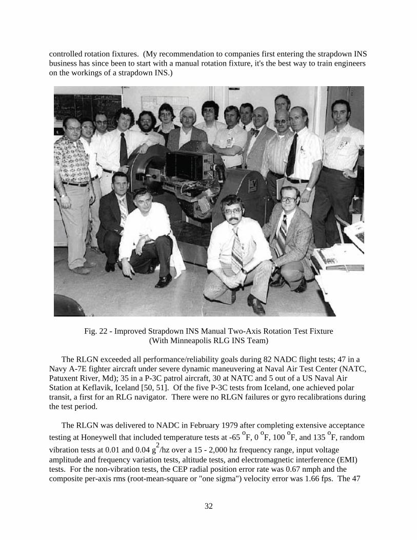
32
controlled rotation fixtures. (My recommendation to companies first entering the strapdown INS business has since been to start with a manual rotation fixture, it's the best way to train engineers on the workings of a strapdown INS.)
Fig. 22 - Improved Strapdown INS Manual Two-Axis Rotation Test Fixture (With Minneapolis RLG INS Team)
The RLGN exceeded all performance/reliability goals during 82 NADC flight tests; 47 in a
Navy A-7E fighter aircraft under severe dynamic maneuvering at Naval Air Test Center (NATC, Patuxent River, Md); 35 in a P-3C patrol aircraft, 30 at NATC and 5 out of a US Naval Air Station at Keflavik, Iceland [50, 51]. Of the five P-3C tests from Iceland, one achieved polar transit, a first for an RLG navigator. There were no RLGN failures or gyro recalibrations during the test period.
The RLGN was delivered to NADC in February 1979 after completing extensive acceptance testing at Honeywell that included temperature tests at -65 oF, 0 oF, 100 oF, and 135 oF, random vibration tests at 0.01 and 0.04 g2/hz over a 15 - 2,000 hz frequency range, input voltage amplitude and frequency variation tests, altitude tests, and electromagnetic interference (EMI) tests. For the non-vibration tests, the CEP radial position error rate was 0.67 nmph and the composite per-axis rms (root-mean-square or "one sigma") velocity error was 1.66 fps. The 47
33
A-7 flight tests were of approximately 1.5 hrs flight duration, all using a 0.5 minute warm-up time, 21 with a 5.5 minute alignment time (i.e., 0.5 + 5.5 = 6 minute reaction time), 20 with a 3 min reaction time, and 6 with a 1 min reaction time. The CEP rate was 0.74 nmph for the 6 min reaction time flights, and 1.14 nmph for all flights. (Note - The A-7 was not instrumented for velocity accuracy determination.) The 35 P-3C flight tests were of 2 hr typical flight duration, all using a 0.5 min warm-up time, 24 with a 5.5 min alignment time (6 min reaction time), and 11 with a 3 min reaction time. The CEP rate for the 6 min reaction time flights was 0.6 nmph, and 0.63 nmph for all flights. The velocity error per horizontal axis for 24 of the flights was 2.79 fps one sigma. Velocity reference data for the remaining 11 flights was invalid due to numerous failures in the AN/ASN-84 gimbaled INS and associated CP-901 computers used as a velocity reference [50, 51].
COMPETING FOR BOEING 757/767 STRAPDOWN IRS PRODUCTION
Following RLGN program initiation in 1976, Boeing's plans for the next generation commercial aircraft began to firm, and they selected a "fly-before-buy" approach for evaluating potential equipment suppliers on two planned new all-digital airplanes (designated as the 757 and 767) [47]. Potential avionics suppliers were to provide Boeing with a "production prototype" flight test demonstration unit so that performance could be assessed prior to issuing the formal Request For Proposal (RFP). The 757/767 had been forecasted by Boeing for several years and was considered by Honeywell as a key program for first production of the new Minneapolis RLG INS. To comply with the Boeing request, a 757/767 Laser IRS prototype flight test demonstration unit was designed/built in parallel with the RLGN program using a duplicate of the RLGN sensor assembly, electronics, and computer, with Boeing specified aircraft input power and standard ARINC output interfaces (the unit on the rotation table in Fig. 22, packaged into an ARINC standard Full ATR chassis envelope).
To meet the Boeing fly-before-buy tight schedule requirements, the 757/767 Laser IRS
prototype was delivered to Boeing in April 1978 (before RLGN delivery to NADC in February 1979). For flight test evaluation, the Laser IRS prototype was installed in an electronics bay mounted to the seat rails of a Boeing 727-100 test aircraft at Boeing Field, Seattle. Performance was assessed by comparison with a Delco Carousel INS unit mounted similarly behind the Honeywell unit, Boeing and Honeywell engineers controlling the individual INSs during flight tests. Accuracy was measured by manually recording and comparing system outputs at selected check times. To help resolve higher than expected velocity errors observed during flight (but not lab) tests, I had to man the Honeywell INS test console for several hours of nauseating 727 "touch-and-go" flight maneuvers at the Moses Lake, WA landing strip during gain calibration of a Sperry automatic landing system. (Honeywell engineer Walt Barniskis, also supporting the flight tests, had to employ "barf bag" survival tactics during the maneuvers). By constantly monitoring the display during turn-arounds (and hoping to avoid airsickness in the process), ground speed was compared during low forward acceleration (a measure of along-track velocity error), and track-angles were compared under low turning rates (a measure of cross-track velocity error when multiplied by ground speed). (Previous flight tests had ignored track-angle comparisons, the more difficult of the two because of the need to synchronize data measurements under momentary low turning rate maneuver segments. Ground-speed measurements were simpler because it is relatively constant, even under maneuver turns).

34
On returning to Boeing Field after the grueling flight test completed, it was discovered that there had been an error in initially aligning the Carousel before takeoff, so test results were invalid. One useful result, however, was visual observation that a Schuler velocity error oscillation was triggered in the Honeywell system while waiting for takeoff clearance at Boeing field (The same magnitude oscillation remained after returning to Boeing field at test completion, proving there were no other significant additions during the flight test). On immediately questioning the pilot if anything unusual had occurred during the hold for takeoff, I was told that the 727 air-conditioning system had been turned on. Later discussions with Boeing personnel revealed that this particular 727-100 aircraft had unusually large ground noise levels on its 400 Hz avionics power buss. Attempting to duplicate the effect back at Honeywell, a Schuler oscillation was "successfully" induced in the Laser IRS prototype test unit after several attempts by injecting extreme levels of conducted electromagnetic interference (EMI) into the system input power lines. The effect has since been eliminated in production units by EMI focused electrical grounding plane design to avoid triggering error pulses on RLG inputs to the system computer.
The Honeywell 757/767 Laser IRS prototype had no failures during the Boeing test period that included 50 system turn-ons, 190 hours of lab testing, and 70 hours of flight testing under various flight conditions. Composite position accuracy was less than 2 nmph 95% radial probable error [47], the commercial equivalent of a 1 nmph CEP military INS accuracy designation. The composite 95% probability per axis velocity error was 7.2 knots (equivalent to a 6 fps one sigma military INS designation), meeting the 8 knot 95% 757/767 Boeing velocity accuracy goal, but higher than expected. The factor of 2 velocity error increase over the 3 fps one sigma RLGN design goal was attributed to conducted noise on the 727 400 Hz input power lines (as experienced during the special velocity test noted previously). This interpretation is further supported by the 1979 RLGN flight tests by NADC on the P-3C aircraft (discussed previously), where the measured velocity accuracy was better than the RLGN 3 fps one sigma goal. (Recall that the 757/767 Laser IRS prototype used a duplicate of the RLGN sensor assembly, electronics, and computer).
Honeywell recognized that their selection for the 757/767 IRS production contract would
entail a significant risk for Boeing, even following a successful Laser IRS prototype 1978 flight test evaluation. To demonstrate confidence in RLG technology, Glen Peters, Vice President of Operations at Honeywell Minneapolis, then made a bold decision to initiate build of a GG1342 RLG manufacturing facility in Minneapolis before receiving any RLG production contracts. The decision was founded on Honeywell's experience building several GG1342s that met accuracy specifications, and the benefit of forecasted production efficiencies defined under the RLG portion of the US Defense Department Joint Services program at Honeywell, ongoing since 1976. With Honeywell Corporate approval, construction began prior to 1978 for a facility capable of supporting production deliveries for future forecasted Honeywell RLG INS contracts.
The Boeing IRS multi-year procurement RFP was issued in 1978 for triple-redundant
installations on the 757 and 767 aircraft. With construction of the new GG1342 production facility well under way, following the success of the Laser IRS flight test program at Boeing, Honeywell was well positioned to respond to the forthcoming multi-year procurement RFP. However, meeting traditional aircraft INS accuracy (a strength for the Honeywell RLG IRS design approach) was not a requirement, but a goal for the 757/767 IRS. This effectively
35
provided a technical edge to Honeywell's competitors (Teledyne and Litton), expected by Honeywell to propose a lesser accuracy IRS using strapdown TRGs compared to the navigational accuracy achieved with the RLG IRS.
Accuracy requirements in the 757/767 IRS performance specification stemmed from
previous Boeing analyses forecasting comparable life-cycle costs for a centralized strapdown inertial system providing outputs for all flight management functions, versus costs normally experienced using dedicated inertial sensors for each function (e.g., attitude/heading referencing, air-data velocity damping, magnetic heading detection, stability augmentation, etc. Note - In flight control terminology, "attitude" refers to roll/pitch angular orientation from the horizontal, "heading" refers to angular orientation around the vertical relative to north. In general inertial navigation terminology, "attitude" refers to the total angular orientation relative to a defined reference coordinate frame.) An inertial navigation capability was considered a useful benefit for automatic-landing augmentation, horizontal acceleration insensitive attitude measurement, wind-shear detection, anti-skid implementation, true vertical velocity, etc., but a long-term goal for anticipated future use of the twin-engine 757/767 medium range aircraft on longer-range over-water flights. (During that time period, the US Federal Aviation Administration FAA would only certify transoceanic flights for 3 or 4 engine aircraft like the DC-10 or 747 having a 2 nmph 95 % radial error probability navigational accuracy capability). To maintain competiveness with all potential IRS suppliers, the Boeing RFQ specified a requirement of 4 (not 2) nmph 95% radial error probability [47]. However, to justify introduction of new strapdown IRS technology on the 757/767, Boeing studies had also determined that a factor of 2.5 decrease was also required in IRS unit cost (based on procurement in 1978) compared to gimbaled INS unit costs experienced with the 747 [47]. The IRS unit cost requirement was also informally made known to the potential 757/767 IRS RFP responders.
Concerned that Teledyne, and particularly Litton (with extensive TRG production
experience), would meet the Boeing IRS cost target, Honeywell made a bold decision to bid the program at a cost deemed favorable to Boeing for the multi-year guaranteed-reliability fixed-price contract. A key part of the bid decision was a forecasted low cost for RLGs in high-volume production based on a predicted learning curve for a not-yet operational production line, assuming that no potential long-term reliability problems would develop in the future (e.g., RLG seal leakage or mirror coating long-term degradation). Based in part on the success of the Honeywell LINS and Laser IRS flight test programs, Honeywell's strong commitment to RLG technology as evidenced by the earlier decision to build the GG1342 production facility, and favorable cost proposal, Boeing selected Honeywell for the 757/767 IRS production program [47]. The contract was finalized on November 21, 1978. (Boeing confidence building in RLG technology for the 757/767 actually began one year prior to the 1975 LINS Holloman flight tests, from measurements taken on a GG1300 RLG consigned to Boeing for test. Particularly impressive to Boeing engineers was the remarkable scale factor repeatability of an RLG under wide-angle motion, with zero asymmetrical error. Note - Strapdown gyro asymmetrical scale factor error can be a major error source in airborne applications under continuous small angle oscillatory motions normally experienced during flight.)
Fig. 23 is a photo of the Honeywell production 757/767 IRS showing the packaging
arrangement in the designated ARINC new standard 10-MCU chassis. A change from the Laser IRS prototype is use of a Sundstrand QA-2000 quartz pendulum accelerometer, selected for the

36
Fig. 23 - Honeywell Production IRS For Boeing 757/767 Aircraft
IRS based on cost considerations and demonstrated required accuracy under heaterless operation [14 Chapt 4, 15 Chapt 3]. (Systron Donner also proposed a quartz-pendulum configured accelerometer in lieu of the more expensive 4841 fluid-damped Lance accelerometer). The QA-2000 is an extended version of the QA-1000 tactical missile grade accelerometer used on ATIGS. More than an order of magnitude accuracy improvement was obtained (over the QA-1000) using a modified plating process for force-rebalanced current across the quartz pendulum hinge (with temperature measurement/modeling/calibration to eliminate repeatable errors). The QA-2000 has subsequently been used in Honeywell military RLG strapdown systems.
Fig. 24 is a photo of the production GG1342 configuration for the 757/767 IRS built in the
new Honeywell production facility. Note the thermal packaging symmetry about the performance critical cathode axis and elimination of heat producing electronics from the gyro case (compared with the GG1300 Fig. 10 configuration). Except for readout amplifiers and ballast resistors used to set discharge current in each individual gyro, all gyro electronics are packaged on interchangeable cards to mount in the INS electronics compartment. An unexpected benefit was an improvement in recorded gyro reliability because gyro electronics failures are then assigned to the system rather than the gyro.
It is interesting to note that the centralized inertial sensing IRS concept was only accepted for
the 757/767 after a lengthy struggle within Boeing between proponents (notably Jack Shaw [4]) and advocates of the traditional approach of using dedicated inertial sensors for each aircraft function (e.g., attitude, heading, stability augmentation). A key deciding factor was the forecasted cost for the integrated IRS approach (with its added performance benefits) compared

37
Fig. 24 - GG1342 RLG Production Configuration
to traditional sensor/system costs. Boeing's cost estimate was based in part on Teledyne TRG experience acquired on Jack Shaw's in-house strapdown program. Ironically (based on rumors at Honeywell), Teledyne's TRG IRS proposal cost was significantly higher than Honeywell's. It was also later learned that Honeywell's cost-compatible proposal had actually been based on a flawed assumption of the competition's technical capabilities. Both Litton and Teledyne participated in the IRS competition as anticipated, but only Teledyne delivered a flight test system prototype. Litton eventually delivered a tuned-rotor gyro/electronics lab test unit, but neither the Teledyne or Litton delivered equipment exhibited the maturity required by Boeing for a commercial airplane program [47]. One can speculate on whether a centralized IRS approach would have ever been used on the 757/767 had not the Honeywell laser gyro IRS cost proposal been compatible with Boeing's forecasted requirement. Fortunately for Honeywell, following several years of production experience, the GG1342 RLG actually proved to be lower in cost and higher in reliability than the basis for the 757/767 IRS proposal. It is also interesting to note that the in-house centralized-versus-dedicated inertial sensing struggle continued at Boeing, even after Honeywell IRS selection, finally ending due to Phil Fenner's individual perseverance with 757/767 flight management function groups to use only IRS inertial sensing data. The one remaining exception was the flight-data recorder accelerometer triad [47].
EPILOGUE
After the Boeing IRS contract award, the Honeywell Minneapolis INS design group was divided into two sections; one for commercial production INS development, the other for military INS system development, the latter having the initial task of designing a new RLG

38
strapdown system that met US Air Force F3 standard INS design specifications. Shortly thereafter in 1980, I left Honeywell to form Strapdown Associates, Inc., a small Minneapolis based engineering firm for strapdown system analysis, software design, developmental consultation, and engineering education. The Honeywell charter was subsequently again revised, transferring military strapdown aircraft INS programs back to the Florida facility. Five years after the RLGN program and Boeing Honeywell 757/767 contract award, the first RLG INS military aircraft production contract was awarded to Honeywell Florida to retrofit the F-15D strike aircraft INS, thus completing the "back-door" process.
Following the RLGN and Boeing Honeywell contracts, Litton and Kearfott initiated major
new RLG INS development programs, Litton receiving an Air Force RLG technology improvement contract that led to a new dielectric mirror deposition process for reduced back-scatter. Both Litton and Kearfott were awarded dual-source development contracts under the US JCMPO (Joint Cruise Missile Program Office) for RLG IMUs (Inertial Measurement Units) on a new Medium Range Air To Surface Missile (MRASM). The MRASM program was eventually cancelled but in the process provided valuable funding for RLG INS design/development at the two companies. Litton and Kearfott were eventually awarded dual source development contracts for the strapdown RLG based Carrier Aircraft Inertial Navigation System (CAINS II) now used on Navy aircraft carrier based aircraft (replacing original Litton gimbaled INS based CAINS equipment). By 1990, virtually all worldwide INS production facilities had become strapdown technology based.
Following the 1975 LINS and MICRON C-141 flight tests [48, 52], the MICRON program was never funded by the Air Force for full-scale production development. After LINS program success, Sperry discontinued RLG design activities. Garnet magnetic-mirror based RLG technology development was continued at two Northrop Divisions for tactical missile and aircraft INS application, but was soon terminated. Hamilton Standard discontinued the DILAG program in the late 1970s, selling technology rights to Raytheon for their Multioscillator 4-beam RLG. RLG work at Raytheon was discontinued in 1985 with technology rights then sold to Litton. Based in part on previous multioscillator research activities initiated by Litton in 1974, further design improvements (including software compensation) led to the Litton production version 4-beam ZLG (Zero-Lock Laser Gyro) [53]. Both ZLG and mechanically dithered RLGs have since been used in Litton inertial systems, the choice depending on application requirements. Kearfott and Honeywell RLG configurations have remained exclusively based on mechanical dither for lock-in compensation.
In the late 1980s, the FAA certified the 757 and 767 for medium to long-range transoceanic
operation due to their demonstrated twin jet engine high reliability. Honeywell Minneapolis commercial RLG inertial system production continued to dominate the US non-military aircraft INS industry, expanding to Boeing 737, 747, 777, 787, Air Bus 310, 320 commercial aircraft, and numerous general aviation business jets. Management/marketing control of the Honeywell Minneapolis INS facility was eventually transferred to the Honeywell Phoenix Division (originally Sperry Aerospace and purchased by Honeywell in 1986). Sundstrand Data Control (manufacturer of the QA-2000 accelerometer used in Honeywell RLG INSs) was purchased by Allied Signal in 1993, eventually becoming part of Honeywell after Allied Signal's purchase of Honeywell in 1999 and the overall Allied Signal company renaming to Honeywell (a "back-door" process with a triple-reverse flip). Litton (now a part of Northrop Grumman) became an
39
equal competitor of Honeywell's Florida Division for US military airborne strapdown INS production, much of it targeted for retrofitting gimbaled INS equipment on existing aircraft. Kearfott remained in the RLG INS business but never achieved the prominence of Honeywell and Litton.
With strapdown technology successfully applied to 757/767 integrated flight management,
US military advanced INS development activities in the 1980s began to focus on applying strapdown INS sensor outputs for high performance fighter aircraft flight control; e.g., the NADC/Litton ISSA (Integrated Inertial Sensor Assembly) Program [54], and the AFAL/McDonnell-Aircraft MFCRS (Multifunction Flight Control Reference System) Program [55]. Wider bandwidth for fighter compared to commercial aircraft autopilot sensors dictated more sophisticated signal processing to reduce quantization noise and sensed RLG mechanical dither induced sensor assembly vibration. Survivability under battle conditions specified physical separation between redundant sensor installations. System approaches investigated incorporated dual redundant strapdown orthogonal-sensor INS configurations each providing accurate position/velocity/attitude/heading outputs. The INSs were mounted in skew alignment relative to one another, generating 6 angular-rate/acceleration flight control signals for skewed sensor failure detection/correction and equivalent orthogonal data output generation (i.e., the equivalent of quad redundant orthogonal sensor triads). Physical separation between sensors required additional signal conditioning for vehicle bending mode suppression and removal of angular maneuvering induced relative acceleration between widely separated skewed accelerometers on forming orthogonal acceleration outputs. Feasibility was tested in an F-15 fighter aircraft with 12 feet separation between INS mountings. For flight testing, orthogonally formed rate/acceleration outputs were substituted for the test aircraft autopilot sensor signals [54, 55] under various software controlled synthetic sensor failures [54]. Test results demonstrated equivalent aircraft performance with the substitute signals, and no noticeable transient generation during simulated failure detection/correction. Integrated skewed inertial sensor technology was then planned for a new US Navy A-12 carrier based strike fighter (a stealth replacement for the aging A-6 intruder). In the face of extensive overruns, however, the A-12 program was subsequently cancelled.
The Boeing commercial 777 became the first aircraft to use a skewed redundant strapdown inertial sensor assembly, all sensors mounted to a common mounting block, the system provided by Honeywell in a skewed 6-sensor hexad configuration using new 2-inch per side GG1320 RLGs. (GG1342 design/production learning applied to the GG1320 produced accuracies comparable to original GG1342s.) The hexad input axis geometry for the gyros and accelerometers places one axis along the aircraft yaw axis (i.e., approximately vertical during straight and level flight), with the remaining five axes positioned uniformly on the surface of a cone (at 72 degree intervals) for which the sixth (yaw) sensor axis is the cone axis. The angle between the cone surface sensor axes and the yaw sensor axis is 63.43 degrees, or 26.57 degrees from each cone sensor axis to the aircraft roll/pitch plane. This geometry also makes the angle between any two of the six sensor axes equal to 63.43 degrees (or 180 - 63.43 = 116.57 degrees, depending on input axis polarity).
The 777 hexad common sensor mount provides rigid alignment between all sensors, allowing
failure detection/correction for up to two gyro or accelerometer failures for navigation as well as flight control. An FAA minimum requirement for commercial aircraft dispatch is for two

40
operating independent sources of primary attitude data (plus two independent navigation data sources on transoceanic flights). To assure dispatch with a single failed attitude or navigation reference source, Boeing aircraft have traditionally been configured with triple redundant navigation/attitude capabilities. The equivalent of quad redundancy provided by the hexad allows time-unlimited dispatch with one navigation/attitude source failure, the equivalent of carrying a "spare" source during flight (the "spare is in the box" Boeing slogan). Note - The dispatch capability with one navigation failure was introduced on transoceanic commercial aircraft to reduce flight cancellation due to the unreliability of original gimbaled INS equipment (less than a few hundred hours mean operating time between random failures - MTBF). Design improvements eventually increased commercial aircraft gimbaled INS reliability to 2,000 hours MTBF. Commercial strapdown RLG inertial systems have experienced greater than 20,000 hours MTBF.
Quad redundant orthogonal strapdown sensor configurations (similar to the 757/767 units)
are being used on the new Boeing 787 commercial aircraft. For 787 IRU (Inertial Reference Unit) source selection, Boeing required that bidders meet a non-negotiable target price equal to Boeing's original goal for the 757/767 IRS procurement. Factored for inflation since 1978, this required a 7-fold decrease in IRU price compared to the 757/767 IRS goal (and a 20-fold decrease in price compared to original commercial gimbaled systems). Honeywell won the contract using GG1320 RLGs, based on two separate performance specifications. (The Boeing RFP allowed for negotiable IRU performance.) Two of the four IRUs provide the standard suite of attitude, heading, angular rates, accelerations, etc., plus inertial navigation outputs that meet the FAA standard of 2 nmph 95% radial probability accuracy. A third source of 787 navigation data is provided from GPS (basic equipment on Boeing aircraft since first introduced on the 747), thus allowing dispatch for transoceanic flight with two sources of navigation data in the event of any single navigation source failure. The remaining two 787 IRUs, although functionally and mechanically identical to the navigation accuracy units, meet a reduced performance requirement (by approximately a factor of 3), do not transmit position/velocity signals, but do output the standard flight control suite of attitude, heading, angular rates, etc. This allows Honeywell to use lower performance RLGs from the GG1320 production line for the reduced accuracy units. The combined four IRUs provide quad redundant flight control outputs, allowing dispatch with any single IRU failure while carrying a spare unit for flight control data during flight.
After a 20-year development cycle beginning in 1978, fiber-optic-gyro (FOG) technology
[12, 14 Chapt 14, 15 Chapt 7] has emerged as a cost-competitive alternative to RLGs in many strapdown applications, most prominently strapdown AHRS (Attitude, Heading Reference Systems). Although demonstrating equivalent bias accuracy for comparable cost in INS applications, FOG technology has yet to achieve the scale factor accuracy routinely provided by RLGs. FOGs have begun to see limited use in high accuracy gimbaled systems where excellent scale factor performance is not required (e.g., the new Trident II submarine launched ballistic missile guidance set).
The GG1342 ring laser gyro is still in production at Honeywell.

41
CONCLUSIONS
Development of a successful inertial navigation system entails the melding of several sophisticated design disciplines (mechanical, electrical, optical, thermal, computer, analytical, software) most at the limits of existing technological capabilities, into a producible, reliable, maintainable product providing required accuracies over extreme environments, at a product cost competitive with companies having long-term inertial navigation design and manufacturing experience. Entering the inertial navigation business requires a significant multi-year company investment for product development and design/production equipment/facilities. Many companies that have tried, eventually failed to successfully complete the process.
The likelihood of success for a new inertial navigation business increases if the inertial product is based on emerging technologies not previously available to competing established companies (e.g., lasers, fiber-optics, low-cost LSIC-based computers). Success likelihood is enhanced if the product development program is allowed to proceed in logical engineering steps, unencumbered by market-driven schedule constraints. One of the fortunate advantages for the Honeywell LINS program was the inadvertent relief from schedule pressure during most of the design cycle, afforded by the "Go-slow, monitor-the-market" strategy directed by Honeywell management. As many engineering managers will attest, this unfortunately is not the usual situation. Perseverance (sometimes in the face of internal or external company politics), patience, innovative engineering, and luck play major roles along the path to success.
Inertial sensor design is a frustrating time consuming iterative process of attempted design modifications/tests to improve/validate performance based on immeasurable material properties under limited funding and program schedule constraints. With luck, newly designed inertial sensors will simplify the solution to technical obstacles that will assuredly be encountered. The success of LINS and its follow-on programs can ultimately be attributed to two primary factors: 1) The inherent characteristics of mechanically dithered ring laser gyro technology that required relatively few design improvements (compared to other inertial components), with uncovered problems readily identified and corrected by design change and/or compensation, and 2) The unexpected good fortune of having accelerometer technology originally developed for less demanding requirements, easily modified for airborne strapdown INS accuracy under heaterless operation.
APPENDIX - RV "FLIES" THROUGH ON-THE-GROUND TESTS
From Onan News No. 3, 1975, Provided Courtesy of Cummins Power Generation Inc.
A group of electronics engineers spent several weeks recently cruising around the Twin
Cities lately in a sleek GMC recreational vehicle. They weren't on a bus tour, though. The "recreational" vehicle was in fact a specially-modified mobile electronics laboratory in which they were conducting some novel field tests.
The engineers, members of Minneapolis-based Honeywell, Incorporated's Government and
Aeronautical Products division, were testing the new Laser Inertial Navigation System (LINS) developed by Honeywell for use in military aircraft. When the Army, Navy, and Air Force

42
viewed preliminary reports on the LINS, they were so interested that Honeywell was asked to accelerate its testing program. Faced with accumulating a quantity of test data in a limited period of time, Honeywell engineers conceived the idea of testing the LINS on the ground in the special vehicle, rather than in the air. Following delivery of the system to the Department of Defense in April, actual flight tests were begun at Holloman Air Force Base in New Mexico.
The interstate highway system provided a serendipitous test environment for the LINS.
Federal government surveys have precisely determined the latitude and longitude of every bridge and underpass that is part of the interstate system. The engineers simply drove the interstate highways, recording the LINS bearings for each surveyed landmark, and checking them against the official survey data to compute the LINS' error rate.
Time was another factor used in the test procedure. Each test trip was timed to last around
84 minutes. That is the approximate time required for a theoretical pendulum suspended from the earth's surface to its center to complete one swing, and provides a standard against which navigational systems can be measured.
To conduct these simulated 'flight tests', the engineers needed a rather special vehicle. Their
mobile test lab was outfitted by R & R Industries, Inc., a Minneapolis firm specializing in custom vehicle modifications.
"We began with an empty shell - just the basic GMC transmode chassis, which is especially
adaptable to modification," said Richard Wiessner, president of R & R. "In addition to the LINS test equipment, we installed office and workshop areas, dinette, washrooom, etc. - all the facilities necessary to create a completely independent traveling laboratory."
One more special feature was needed to make the vehicle completely self-sufficient: a
reliable power source to run everything. So R & R equipped the lab with two Onan 6,000-watt gasoline powered 6.ONH-1R/9000E Power Drawer electric generator sets. The sets were supplied by Flaherty Equipment Corp., Onan's Minneapolis distributor.
One of the Onan sets provides power for the LINS equipment itself. "In a plane, the LINS
would run off the aircraft engine power," Weissner explained. "The other set runs the lights, heating and air conditioning, plumbing, and other miscellaneous 110-volt equipment on board."
The vehicle also carries four 12-volt batteries, Weissner mentioned, two in the chassis and
one for each of the two Onan sets as a backup. The Onan-powered land vehicle, originally chosen chiefly as an expedient alternative to an
airplane, proved to have several advantages over a plane. Installing the LINS in the GMC vehicle was far less costly than outfitting an airplane would have been. The roomy interior of the mobile lab provided the engineers with the ample working space a plane would have lacked. The smooth ride enabled them to test the LINS under conditions that closely approximate flight dynamics.
Most important, the vehicle gave them the time and convenience they needed. No licensed
pilot was necessary; the engineers could simply climb in and drive it. No flight clearance was

43
required, and the lab was never 'grounded' by inclement weather. In approximately two months of testing, sufficient test data was collected to permit Honeywell to deliver LINS to the government. The tests indicate that the system is quite capable of meeting the high accuracy standards set by the Department of Defense.
ACKNOWLEDGMENT
I would like to express my appreciation to my wife Paula, my daughter Kelly Roscoe (Applied Strapdown Analytics), and the following individuals (company affiliations noted for the 1960s and 1970s) for their helpful comments, suggestions, and encouragement during reviews of this paper: Fred Aronowitz, Walt Barniskis, Earl Carson, Joe Killpatrick, Chuck McClary, Glen Peters, Ted Podgorski, Cal Senechal, Dave Thymian, Hal West (Honeywell); Ken Bachman, Ed Dinter, Bob Skoyles (NADC); Bob Christenson, Merritt Mullen (NWC); Mel McIntyre, Jack Shaw (Boeing); Bob Acker (Kearfott); Jerry Gilmore, George Schmidt (CS Draper Lab). The "Blazing Gyros" title is attributed to Bob Christenson (NWC) for his response many years ago to my suggestion that the events of this article would make an interesting Hollywood movie.
REFERENCES [1] MacKenzie, Donald, Inventing Accuracy, Chapter 2, The MIT Press, 1993, Cambridge MA,
London. [2] Minor, J. W., “Low-Cost Strapdown-Down Inertial Systems”, AIAA/ION Guidance and
Control Conference, August 16-18, 1965. [3] Eberlein, A. J. and Savage, P. G., "Strapdown Cost Trend Study And Forecast", Prepared
Under Contract NAS2-8065, Report No. CR-137585, Jan. 1, 1975. [4] Shaw, Jack C., "Benefits of Strapdown Over Gimbaled Systems for Aircraft Application",
IEEE National Aerospace & Electronics Conference (NAECON), Dayton, Ohio, 18-20 May 1976.
[5] Gilmore, J.P., "A Non-Orthogonal Gyro Configuration", MIT/IL Report T-472, January
1967. [6] Gilmore, J.P., Cooper, R. J., "SIRU Development- Final Report, Volume 1, System
Development", CSDL R-746, Draper Laboratory, (NASA-CR-136033). [7] Gilbert, John F., McIntyre, Melville D., Olbrechts, Shaw, Jack C., "Integrated Strapdown Air
Data System", US Patent # 4303978, April 18,1980. [8] Hruby, Ronald J., Bjorkman, William S., "Flight Test Results of the Strapdown Hexad
Inertial Reference Unit (SIRU)", NASA TMX-73,223, Ames Research Center, Moffit Field, Calif., July 1977.
44
[9] Peterson, Roland, "Advantages of Gimbaled Inertial Navigation Systems", IEEE National Aerospace & Electronics Conference (NAECON), Dayton, Ohio, 18-20 May 1976.
[10] Klass, Philip J., "Ring Laser Device Performs Rate Gyro Angular Rate Sensor Functions",
Aviation Week and Space Technology, Feb. 11, 1963, pp. 98-103. [11] Savage, P. G., “Strapdown Sensors”, Strapdown Inertial Systems - Theory And Applications,
NATO AGARD Lecture Series No. 95, June 1978, Section 2. [12] Savage, Paul G., "Advances In Strapdown Sensors", Advances In Strapdown Inertial
Systems, AGARD Lecture Series No. 133, 14-15 May 1984. [13] Warzynski, Capt. Robert R. and Ringo, Ronald L., "The Evolution Of ESG Technology",
AGARD Symposium, June 1971. [14] Lawrence, Anthony, Modern Inertial Technology, Springer-Verlag 1993. [15] Merhav, Schmuel, Aerospace Sensor Systems and Applications, Springer-Verlag New York,
Inc., 1996. [16] Sinkiewicz, J.S., Feldman, J., Lory, C.B., "Evaluation of Selected Strapdown Inertial
Instruments and Pulse torque Loops", Final Report, Volume 1, CSDL R-286, Draper Laboratory, NASA-CR-120427, July 1974.
[17] Killpatrick, Joseph, "The Laser Gyro", IEEE Spectrum, Oct. 1967. [18] Aronowitz, Dr. F., "Fundamentals of the Ring Laser Gyro", Optical Gyros And their
Applications, RTO AGARDograph 339, June 1999. [19] Aronowitz, Frederick, and Collins, R. J., "Mode Coupling Due To Back Scattering In A
HeNe Traveling Wave Ring Laser", Applied Physics Letters, Vol. 9, No. 1, July 1966. [20] Morrison, R., Levinson, Dr. E, and Bryant Jr., B. L., "The SLIC-7 Laser Gyro Inertial
Guidance System", IEEE National Aerospace & Electronics Conference (NAECON), Dayton, Ohio 1977.", ION National Aerospace Symposium, Warminster, Pennsylvania, 27-28, April 1976.
[21] Morrison, R., Levinson, Dr. E, and McAdory, R, "The SLIC-15 Laser Gyro IMU For
Midcourse Missile Guidance", ION National Aerospace Symposium, Warminster, Pennsylvania, 27-28, April 1976.
[22] Feldman, Julius, "Sperry ASLG 15 Laser-Gyro Performance And Error Model", Final
Report, CDCL Report R-989, Prepared Under Contract NAS1-13958, July 1976. [23] Rountree, James P., Burns, John E., and McAdory, Robert W., "Differential Laser Gyro
Technology", IEEE National Aerospace & Electronics Conference (NAECON), Dayton, Ohio, 1975.

45
[24] Bresman, J., Cook, H., and Lysobey, "Differential Laser Gyro Development", ION National Aerospace Meeting, Warminster, Pennsylvania, 28 April 1976.
[25] Stowell, W. K., McAdory, R.W., and Rountree, J. P., "Differential Laser Gyro", IEEE
Southeast Conference, Clemson, South Carolina, 5-7 April 1976. [26] Smith, I. and Dorschner, T., "Clear-Path Four-Frequency Ring Laser Gyroscope", Journal of
the Optical Society of America, Volume 68, pp. 1381, 1978. [27] "A Study of Critical Computational Problems Associated With Strapdown Inertial
Navigation Systems", NASA Report Cr-968, April 1968. [28] Savage, P.G., “A New Second-Order Solution for Strapped-Down Attitude Computation”,
AIAA Joint Automatic Control Conference, Seattle, Washington, August 15-17, 1966. [29] Bortz J. E., "A New Concept In Strapdown Inertial Navigation", MIT Doctoral Thesis, June,
1969. [30] Jordan, J. W., “An Accurate Strapdown Direction Cosine Algorithm”, NASA TN-D-5384,
September 1969. [31] Savage, P. G., “Strapdown System Algorithms”, Advances In Strapdown Inertial Systems,
NATO AGARD Lecture Series No. 133, May 1984, Section 3. [32] Savage, P. G., “Strapdown Inertial Navigation System Integration Algorithm Design Part 1 -
Attitude Algorithms”, AIAA Journal Of Guidance, Control, And Dynamics, Vol. 21, No. 1, January-February 1998, pp. 19-28.
[33] Savage, P. G., “Strapdown Inertial Navigation System Integration Algorithm Design Part 2 -
Velocity and Position Algorithms”, AIAA Journal Of Guidance, Control, And Dynamics, Vol. 21, No. 2, March-April 1998, pp. 208-221.
[34] Roscoe, K. M., “Equivalency Between Strapdown Inertial Navigation Coning and Sculling
Integrals/Algorithms”, AIAA Journal Of Guidance, Control, And Dynamics, Vol. 24, No. 2, March-April 2001, pp. 201-205.
[35] Savage, Paul G., Strapdown Analytics - Second Edition, Chapter 7, Strapdown Associates,
Inc., Maple Plain, Minnesota, 2007. [36] Miller, R., “A New Strapdown Attitude Algorithm”, AIAA Journal Of Guidance, Control,
And Dynamics, Vol. 6, No. 4, July-August 1983, pp. 287-291. [37] Ignagni, M. B., “Optimal Strapdown Attitude Integration Algorithms”, AIAA Journal Of
Guidance, Control, And Dynamics, Vol. 13, No. 2, March-April 1990, pp. 363-369.

46
[38] Ignagni, M. B., “Efficient Class Of Optimized Coning Compensation Algorithms”, AIAA Journal Of Guidance, Control, And Dynamics, Vol. 19, No. 2, March-April 1996, pp. 424-429.
[39] Mark, J. G. and Tazartes, D. A., "Tuning Of Coning Algorithms To Gyro Data Frequency
Response Characteristics", AIAA Journal Of Guidance, Control, And Dynamics, Vol. 24, No. 4, July-August 2001, pp. 641-647.
[40] Savage, P. G., “Coning Algorithm Design By Explicit Frequency Shaping”, AIAA Journal
Of Guidance, Control, And Dynamics, Vol. 33, No. 4, July-August 2010, pp. 1123-1132. [41] Savage, P. G., “Explicit Frequency Shaped Coning Algorithms for Pseudoconing
Environments”, AIAA Journal Of Guidance, Control, And Dynamics, Vol. 34, No. 3, May-June 2011, pp.774-782.
[42] Podgorski, T.J. and Thymian, D.M., "Design and Development of the AA1300Ad02 Laser
Gyro", NASA Report No. CR-132261, pp. 10 and 11. [43] Savage, Paul G., "The Honeywell Laser Inertial Navigation System (LINS)", IEEE National
Aerospace & Electronics Conference (NAECON), Dayton, Ohio, June 1975. [44] Savage, Paul G. and Ignagni, Mario B., "Honeywell Laser Inertial Navigation System
(LINS) Test Results", IEEE Ninth Joint Services data Exchange Group For Inertial Systems, St. Petersburg, Florida, 18-19 November 1975.
[45] Savage, Paul G., "Laser Gyros In Strapdown Inertial Navigation Systems", IEEE Position
Location and Navigation Symposium, Nov. 1-3, 1976. [46] Duncan, Robert R., "MICRON - A Strapdown Inertial Navigator Using Miniature
Electrostatic Gyros", SAE Aerospace Control and Guidance Systems Committee, Paradise Valley, Arizona, 15-17 May 1974.
[47] Fenner, Phillip J.,"Requirements, Applications, And Results Of Strapdown Inertial
Technology To Commercial Airplanes", AGARD Lecture Series No. 133 - Advances In Strapdown Inertial Systems, 14-15 May 1984.
[48] "Development Test of the Honeywell Laser Inertial Navigation System (LINS)", Final
Report ADTC-TR-75-74, Central Inertial Guidance Test Facility, 6585th Test Group, Holloman Air Force base, November 1975.
[49] Savage, P. G., “Calibration Procedures For Laser Gyro Strapdown Inertial Navigation
Systems”, 9th Annual Electro-Optics / Laser Conference and Exhibition, Anaheim, California, October 25 - 27, 1977.
[50] NAVAIRDEVCEN Report NADC-80058-40, "Advanced Development Model Ring Laser
Gyro Navigator, A-7E Aircraft Flight Test Results", 15 August 1980.
47
[51] Bachman, Kenton L., "Ring Laser Gyro Navigator (RLGN) Flight Test Results", ION Journal, Vol. 28 No. 3, 1981, pp. 214-223
[52] "Development Flight Testing of the N-57A Inertial Navigation System", Final Report
ADTC-TR-75-86, Prepared by the Central Inertial Guidance Test Facility, 6585th Test Group, Holloman Air Force Base, November 1975.
[53] Volk, C.H., Gillespie, S.C., Mark, J.G., Tazartes, D.A., "Multioscillator Ring Laser
Gyroscopes And Their Applications", Optical Gyros And their Applications, RTO AGARDograph 339, June 1999.
[54] Savage, P. G., Introduction To Strapdown Inertial Navigation Systems, January 10, 2010,
Twelfth Printing, Strapdown Associates, Inc., 1981-2010, pp.327A-327D. [55] Sebring, D. L., Perdzock, J. M. , and Young, Capt. J. T., "Application of Multifunction
Strapdown Inertial System", Advances In Strapdown Inertial Systems, NATO AGARD Lecture Series No. 133, May 1984, Section 8.

48
ABOUT THE AUHOR
Paul G. Savage is an internationally
recognized expert in the design and test of strapdown inertial navigation systems, and president of Strapdown Associates, Inc., a company he founded in 1980. Strapdown Associates has provided software and engineering services to government agencies and aerospace companies for strapdown inertial system configuration definition, flight software development, system simulation, and testing. Mr. Savage has published and presented several papers on strapdown inertial navigation systems and associated computational elements.
From 1974 to 2009 he served as an
author/speaker on several NATO AGARD and RTO technology transfer lecture series tours. From 1981 to 2009, Mr. Savage
provided his Introduction To Strapdown Inertial Navigation Systems course to the aerospace industry. Since 2011 he has provided a two-day focused version of the Intro To Strapdown course on-site at host facilities in the continental United States. He has written and published the textbook Strapdown Analytics (available from Strapdown Associates) detailing the analytical aspects of strapdown inertial navigation system design.
From 1963 to 1980, Mr. Savage was
employed at Honeywell Avionics Division as Senior Principal Engineering Fellow where he led engineering design teams and provided technical consultation to Honeywell engineering managers for system design, analysis, software development, simulation, and integration/test in the evolutionary development of laser gyro strapdown inertial navigation systems for military and commercial aircraft. From 1971 through 1975, he was the engineering manager and system design engineer for the Honeywell LINS-0 strapdown inertial system, the first to prove the readiness of laser gyro strapdown inertial navigation technology for aircraft applications as demonstrated during a landmark flight test series at Holloman Air Force Base in 1975.
Mr. Savage is a graduate from the
Massachusetts Institute of Technology where he received his MS and BS degrees in Aeronautical Engineering in 1960. He is an Associate Fellow of the AIAA.