journal of magnetic resonance -
TRANSCRIPT

Journal of Magnetic Resonance 198 (2009) 261–270
Contents lists available at ScienceDirect
Journal of Magnetic Resonance
journal homepage: www.elsevier .com/locate / jmr
Cryogenic sample exchange NMR probe for magic angle spinningdynamic nuclear polarization
Alexander B. Barnes a, Melody L. Mak-Jurkauskas a,b, Yoh Matsuki a,b, Vikram S. Bajaj a,Patrick C.A. van der Wel a, Ronald DeRocher a, Jeffrey Bryant a, Jagadishwar R. Sirigiri c, Richard J. Temkin c,Johan Lugtenburg d, Judith Herzfeld b, Robert G. Griffin a,*
a Department of Chemistry and Francis Bitter Magnet Laboratory, Massachusetts Institute of Technology, Cambridge, MA 02139, USAb Department of Chemistry, Brandeis University, Waltham, MA 02454, USAc Plasma Science and Fusion Center, Massachusetts Institute of Technology, Cambridge, MA 02139, USAd Department of Chemistry, Rijksuniversiteit te Leiden, NL-2300 R A Leiden, The Netherlands
a r t i c l e i n f o
Article history:Received 12 February 2009Available online 17 March 2009
Keywords:Dynamic nuclear polarizationInstrumentationHardwareCryogenic MAS
1090-7807/$ - see front matter � 2009 Elsevier Inc. Adoi:10.1016/j.jmr.2009.03.003
* Corresponding author. Fax: +1 617 253 5405.E-mail address: [email protected] (R.G. Griffin).
a b s t r a c t
We describe a cryogenic sample exchange system that dramatically improves the efficiency of magicangle spinning (MAS) dynamic nuclear polarization (DNP) experiments by reducing the time requiredto change samples and by improving long-term instrument stability. Changing samples in conventionalcryogenic MAS DNP/NMR experiments involves warming the probe to room temperature, detaching allcryogenic, RF, and microwave connections, removing the probe from the magnet, replacing the sample,and reversing all the previous steps, with the entire cycle requiring a few hours. The sample exchangesystem described here—which relies on an eject pipe attached to the front of the MAS stator and a vac-uum jacketed dewar with a bellowed hole—circumvents these procedures. To demonstrate the excellentsensitivity, resolution, and stability achieved with this quadruple resonance sample exchange probe, wehave performed high precision distance measurements on the active site of the membrane protein bac-teriorhodopsin. We also include a spectrum of the tripeptide N-f-MLF-OH at 100 K which shows 30 Hzlinewidths.
� 2009 Elsevier Inc. All rights reserved.
1. Introduction
Dynamic nuclear polarization (DNP) increases the sensitivity ofNMR by transferring the large spin polarization from stable para-magnetic centers to the nuclear spin reservoir [1,2]. In recentapplications to biological solids, the enhanced polarization is gen-erated by millimeter wave irradiation of the EPR transitions ofbiradical polarizing agents [3] and is uniformly dispersed to thesystem of interest via proton spin diffusion [4,5]. During the polar-ization process, spin-lattice relaxation mechanisms compete withthe polarization growth in the proton bath. These T1 processesare slower at lower temperatures and cryogenic operation (pres-ently around 85 K) permits the polarization from the electrons toeffectively complete a relayed transfer to such systems as mem-brane or amyloid proteins [6,7] and peptide nanocrystals [8]. Inaddition, in the temperature regime discussed here, the spin polar-ization is proportional to the inverse of the sample temperature;thus, at 85 K the polarization is another factor of approximatelythree larger than at room temperature.
ll rights reserved.
However, conventional low temperature magic angle spinning(MAS) NMR experiments generally suffer from poor experimentalefficiency due to the time required to change samples. In particu-lar, the simple task of switching from a standard sample used toadjust B0 homogeneity, the magic angle, etc. to the sample of inter-est involves warming the probe to room temperature, detaching allcryogenic, radiofrequency (RF), and microwave connections,removing the probe from the magnet, and replacing the sample.Subsequently, the procedure is reversed, with the entire warm-ing–cooling cycle requiring a few hours. This process also increasesmechanical wear and the risk of damage to the microwave wave-guide and mirror system that delivers the millimeter wave radia-tion to the sample.
The sample exchange system described here permits the sam-ple to be changed in a matter of minutes without disturbing theprobe. It is driven by N2 and consists of a custom designed ejectpipe attached to the front of a Revolution NMR (Ft. Collins, CO)MAS stator that mates with a bellowed hole in a vacuum jacketeddewar. Thus, the rotor is ejected through the top of the dewar intoa vacuum jacketed transfer tube running through the magnet bore.A teflon tube on top of the magnet is used to slow and receive thesample. The quadruple resonance (1H, 13C, 15N, and e�) MAS probe

262 A.B. Barnes et al. / Journal of Magnetic Resonance 198 (2009) 261–270
described here is a fourth generation design, and the system (probeplus sample eject) has been operating routinely for over a year andhas dramatically increased the efficiency of our experiments. It isused routinely with an existing 380 MHz/250 GHz DNP spectrom-eter described elsewhere [9,10].
This paper is divided into two sections. First, we describe theoverall system architecture and the instrumentation required forachieving and maintaining cryogenic sample temperatures whilethermally isolating the probe tuning elements. This includes a de-tailed description of the design of the cryogenic sample exchangesystem. The instrumentation section closes with a description ofthe quadruple resonance RF/microwave circuit based on the Schae-fer–McKay air dielectric transmission line design.
In Section 3, we demonstrate the capabilities of the system byproviding illustrative examples, which include a demonstrationof a stable DNP enhancement over multiple sample exchanges, aspectrum showing the exquisite resolution achievable for a peptideat cryogenic temperature, and a precise distance measurement be-tween two selectively-labeled 13C sites in the membrane proteinbacteriorhodopsin.
2. Instrumentation
2.1. System architecture
Fig. 1 shows an overview of the system architecture used forcryogenic DNP/NMR. The major components consist of (left to rightin the figure) the N2 control system, the heat exchanger, the qua-druple resonance MAS probe and finally (moving vertically) thesample chamber and eject pipe, the eject tube, and the receivingand inserting chambers.
For cryogenic MAS experiments, dry pressurized nitrogen gas isseparated into the bearing and drive lines required to spin the sam-ple. The bearing gas passes through a manually controlled pressureregulator, while a standard Bruker MAS unit controls the drive gaspressure. The two independent gas streams transition to evacuatedtransfer lines before entering a heat exchanger that cools the gasesfrom room temperature to �80 K. Both gas streams are then vac-uum insulated from the point they leave the heat exchanger untilthey enter the sample chamber and MAS stator.
During MAS experiments the valves controlling the sample ejectgas at the bottom of the probe and at the top of the eject tube areclosed, thereby forcing the cold MAS gas to exit the sample cham-ber via the vacuum jacketed exhaust line. To exchange the sample,
Fig. 1. Overview of the system architecture for cryogenic MAS experiments and
the spinning is stopped, the exhaust valve is closed and the twoeject valves opened. Next, pressurized room temperature gas isconnected to the exhaust line, and forces the rotor out of the stator,into the eject pipe and tube leading to the top of the magnet. As therotor exits the magnet bore, it is guided into a receiving chamberby a Teflon tube. To insert a sample, the rotor is placed into theeject tube on the top of the magnet and a small flow of gas gentlylowers the rotor into the sample chamber and stator. We now pro-vide a more complete description of these components.
2.2. Heat exchanger and cryogen regulation
To maintain stable temperatures of �90 K for extended periodsof operation, a custom designed heat exchanger is required. Theheat exchanger used in the present experiments is depicted inFig. 2 and is a refinement of a design we described previously[11]. Room temperature N2 gas enters and exits the heat exchangerthrough two sets of rigid vacuum jacketed transfer lines. Vacuuminsulated lines are used on the input to the heat exchanger so thatthe overall cooling capacity is invariant to changes in the level ofthe liquid nitrogen reservoir. The output transfer lines mate to2.5 m flexible transfer lines that connect to the probe. The rigidtransfer lines are fabricated from stainless steel and are individu-ally silver soldered together, and also soldered to the inner heat ex-changer can, as illustrated in Fig. 2.
The heat exchange system is also designed to permit the liquidnitrogen reservoir to be refilled during operation [11] and to allowcontrol of the pressure of the inner heat exchanger vessel (and thusliquid level) that provides the user direct control of the overallcooling capacity. This makes it possible to bring the temperatureof the cryogen to just above its boiling point, while avoiding con-densation that results in pressure pulses in the bearing and drivegas, spinning frequency instability, and ultimately rotor crashes.
For MAS experiments, high pressure (�7.5 bar) dry N2 from anexternal dewar is warmed and passes through multiple ballaststo provide a stable nitrogen gas source. A Bruker MAS control unitfunctions in the same mode as in standard room temperatureapplications—monitoring the spinning frequency with optical fi-bers and maintaining 65 Hz spinning frequency stability up to�6 kHz with tight P.I.D. control of the drive pressure. Bearing gaspressure is controlled manually, bypassing the Bruker unit, and isfed directly into the heat exchanger. A manual override controllingthe main pressure supplied to the MAS control unit allows the user
sample exchange. Thick black lines indicate vacuum-jacketed transfer lines.

Fig. 2. Heat exchanger. The pressure of the inner can is regulated and controls theoutput temperature of the cryogen. The nitrogen reservoir is replenished automat-ically during operation by means of a level sensor and electromechanical valve.
A.B. Barnes et al. / Journal of Magnetic Resonance 198 (2009) 261–270 263
to stop spinning in a controlled manner in the case of loss of mainpressure or power failure.
Manual control of the bearing gas is also implemented to adjustthe gas flow, and thus overall cooling capacity, supplied to theprobe. Typically, at xr/2p = 4 kHz, the drive pressure is 600–900millibar, and the bearing pressure is 700–1400 millibar. At 700millibar bearing pressure we typically achieve temperatures of100 K, whereas at 1400 millibar we can maintain �85 K. We notethat significant gains in the DNP enhancement are realized byreducing the temperature from 100 to 85 K, but defer a more
Fig. 3. CAD drawings of the probe instrumentation needed for cryogenic MAS. (a) Evacuwhile an exhaust transfer line brings the cold cryogens out of the probe without coolingflexible evacuated transfer lines allow for precise control of the temperature. The probe-bcondensation. (b) Cut-out of probe. Multiple optical channels are required for in situ ofrequency. Modifications to the dewar, an angled eject pipe that mates to a commercianeeded for the cryogenic sample exchange system.
detailed discussion of temperature dependence of DNP enhance-ment to a forthcoming manuscript.
2.3. Cryogenic MAS strategies
Selected components of the experimental apparatus that con-nect to the output of the heat exchanger are shown in Fig. 3. Salientfeatures include two flexible transfer lines with integral 50 Wheaters, three vacuum jacketed lines internal to the probe that de-liver cryogens to the sample chamber and safely bring the cold gasout of the probe. We also show a non-magnetic, vacuum jacketeddewar modified with a bellowed hole in the top providing a path-way for sample exchange, and a custom designed eject pipe to di-rect the rotor into and out of the stator.
The vacuum-jacketed dewar and the use of insulating material inthe probe body reduces heat transfer from the probe box and magnetbore, which are maintained at ambient temperature, to the probesample chamber. The use of cryogenic bearing and drive gases,which are required at high flows and pressures for MAS, supplies asignificantly higher cooling power than a traditional dedicated var-iable temperature gas stream, and is more than sufficient to over-come the thermal losses through the probe-body, dewar, andtransfer lines. Our design also maintains the entire sample chamberat cryogenic temperature, in contrast to traditional designs that coolonly the rotor. Cooling the entire sample chamber (the Cu can andbase in Fig. 3b) minimizes temperature gradients across the sample.In implementations of MAS DNP/NMR, the cold spinning gas alsoeffectively overcomes microwave, RF, and frictional heating, espe-cially with an appropriate selection of rotor materials.
Rotors for DNP/NMR are machined from single crystals of sap-phire (Inasco; Quakertown, PA). Sapphire has high thermal con-ductivity, which facilitates active cooling of the sample. It is alsotransparent to the microwaves needed for DNP and to visible lightfor experiments involving optical irradiation of the sample, such ascharacterization of photocycle intermediates of bR [6]. The wallthickness of the sapphire rotor can be optimized to transmit the
ated bearing and drive transfer lines in the probe deliver the cryogens to the probe,the box containing the tuning elements. Heaters (50 W) at the termination of the
ox is purged with a low pressure flow of room temperature nitrogen gas to preventptical irradiation of the sample, temperature sensing, and monitoring of the MASlly available Revolution NMR stator, a GORE-TEX seal, and other modifications are

264 A.B. Barnes et al. / Journal of Magnetic Resonance 198 (2009) 261–270
maximum amount of microwave power to the sample [12], and4 mm sapphire rotors are sufficiently strong to spin routinely atxr/2p 6 10 kHz. Details of the preparation of the drive-tip andspacers for cryogenic use are shown below.
A fiber optic temperature sensor (Fiso Technologies; Quebec,Canada) placed near the rotor (Fig. 3b) provides an accurate read-ing of the sample temperature. This optical sensor is better suitedthan a platinum resistance thermometer, because the wiring of thelatter often acts as an antenna and couples RF pickup to the samplecoil.
As mentioned above, systems that combine room temperaturebearing and drive gas and a variable temperature gas stream direc-ted at the sample can introduce a temperature gradient across thesample. It is possible to minimize this gradient by use of a long zir-conia rotor but long rotors are difficult to fit into conventional89 mm magnet bores [13]. Furthermore, ejection of such long ro-tors requires rotation of the stator with respect to the magnet bore;a process that is difficult to implement in a cryogenic probe andcompromises the adjustment of the magic angle.
2.3.1. Transfer linesDuring cryogenic operation, room temperature bearing and
drive supplies of nitrogen are cooled to �80 K by the heat exchan-ger (Fig. 2) [11] and delivered to the MAS stator with minimal heattransfer from the environment. This is accomplished using flexiblestainless steel transfer lines (Precision Cryogenics; Indianapolis,IN) that connect the heat exchanger to the probe, and non-mag-netic vacuum-jacketed lines in the probe. Heaters and temperaturesensors (50 W) (Lakeshore Cryogenics; Westerville, OH) are in-stalled near the ends of the transfer lines to control the bearingand drive gas temperatures to ±0.5 K, a stability that is requiredto obtain stable DNP enhancements.
The flexible evacuated transfer lines from the heat exchangerare joined to the probe transfer lines with stainless steel, vac-uum-jacketed bayonet fittings (Precision Cryogenics; Indianapolis,IN). A small cryogen gas space between the male and female sec-
Fig. 4. Thermal isolation strategies. (a) Vacuum-jacketed transfer lines used to deliver themagnetic probe-dewar with a bellowed transfer pathway to accommodate the sample e
tions of the joint is sealed by a silicon O-ring at the warm-end joint[14]. These bayonets maintain excellent thermal isolation betweenthe cryogen and environment.
Within the probe, a set of rigid vacuum-jacketed transfer linesconstructed of stainless steel, aluminum, and fiberglass (seeFig. 4a) provide well-insulated transfer of the bearing and drivecryogens to the probe sample chamber. These transfer lines are asignificant improvement over vacuum-jacketed lines made ofglass, which are fragile, and also are commonly connected to thecryogen supply using a glass ball and socket joint that leads to sub-stantial heat transfer. The bottom section of the inner tube is madeof stainless steel that is silver-soldered to the bayonet and transi-tions to aluminum a few inches after the 90o turn into theprobe-body. Stainless steel is not used near the stator because it of-ten becomes slightly magnetic after repeated temperature cycling[15]. This is most evident in degradation of the homogeneity re-quired for high-resolution MAS experiments.
While the inner tube of the transfer line is maintained at cryo-genic temperatures, the outer tube is thermally coupled to theprobe box (ambient temperature) and the sample chamber, whichis maintained at cryogenic temperatures. Thus a non-magneticmaterial with a low thermal conductivity must be used for the out-er tube of the transfer line. 577CR fiberglass (Spaulding; Rochester,NH) is a good thermal isolator and is constructed of layers of fiber-glass sheets of vacuum tight material, resulting in a transfer linesuitable for vacuum applications. We use 577CR fiberglass in thetransfer lines and also in the probe-dewar.
2.3.2. Probe-dewarA schematic of the non-magnetic dewar used to thermally iso-
late the cryogenic probe interior from the ambient temperaturemagnet bore is shown in Fig. 4b. The dewar also prevents the boreof the superconducting magnet from dropping to temperatureswhere the O-ring sealing the magnet cryostat fails. As an addedsafety precaution, a low flow of room temperature purge nitrogengas flows into the magnet bore to ensure a dry environment free of
bearing and drive cryogens and transport the exhaust gas out of the probe. (b) Non-jection pipe (from the bottom) and transfer tube (from the top).

A.B. Barnes et al. / Journal of Magnetic Resonance 198 (2009) 261–270 265
condensation. Finally a bellowed hole in the top of the dewar pro-vides a path for the rotor to enter and exit the MAS stator.
The dewar has an outside diameter of 127 mm and accommo-dates the 93 mm diameter copper can of the probe sample cham-ber. The outer vessel is thin-wall aluminum (Future Metals;Tamarac, FL) and the inner vessel is 577CR. Both vessels are joinedwith epoxy to an aluminum base, which has four semicircularholes needed to attach the dewar to the shim stack on the bottomof the magnet bore. The holes allow for 15� of angular adjustmentof the dewar with respect to the magnet bore, leeway that is re-quired for proper alignment of the sample eject system. Thesemounting holes and details of mating the dewar to the box andmagnet are shown in Fig. 4b.
The aluminum base of the dewar mates to the probe-box via anO-ring to establish the air-tight seal necessary to prevent frost andcondensation during extended periods of use. Copper fingerstockbetween the aluminum base of the dewar and the probe estab-lishes an electrical ground that reduces RF pickup. Both the O-ringand the fingerstock are designed such that the dewar-to-probeconnection is vertically adjustable. In this manner, the vertical po-sition of the probe can be properly aligned with the stationary hor-izontal waveguide [16] that couples the probe to the microwaveoutput from the gyrotron. In addition to forming an air-tight sealto the probe, the dewar must also connect securely to the sampleeject pipe.
Changing the sample from above the magnet requires a vacuumjacketed transfer tube that passes through the top of the dewar.However, connecting the inner and outer vessels of the dewar witha thermally conductive material would compromise the thermalisolation of the dewar. The fiberglass tube shown in Fig. 4b pro-vides a channel for the sample transfer tube, while at the sametime acting as a thermal break to prevent heat transfer betweenthe vessels of the dewar. Beryllium copper bellows connect thefiberglass thermal break to the dewar’s outer vessel and accommo-date the vertical shrinkage of the inner vessel at lower tempera-
Fig. 5. Sample ejection schematics. (a) Cut-away of probe showing the rotor (purple). A binto the vacuum-jacketed sample exchange tube, carrying the rotor from the stator (1) in(4). For sample insertion, the rotor is lowered on a cushion of gas from the top of magnetand is guided by the bottom surface of the eject pipe to make the turn from 54.5� to 0� wipipe is a cone which fits inside the larger cone of the vertical eject tube to allow for adjusattachment allows for a secure coupling into the probe-dewar and proper alignment ofclosed during operation to prevent frost formation, and is remotely opened during samplslowly and safely slow the rotor. (For interpretation of the references to color in this fig
tures (Fig. 4b). Beryllium copper was chosen because it is non-magnetic, yet still malleable enough to expand and contract asneeded during temperature cycling.
2.4. Cryogenic sample exchange
The sample exchange system, including the eject pipe and de-war, is designed to integrate into the 130 mm bore of the380 MHz magnet. Within that space, the rotor must turn from54.7� relative to the magnetic field as it leaves the stator, to 0� withrespect to magnetic field to travel out of the magnet, in a systemthat allows adjustment of the magic angle. A custom designedangled eject pipe (Fig. 5b) (Accelerate Global Sourcing; Austin,TX) bolted to the face of a 4 mm Revolution NMR stator mechani-cally guides the rotor into and out of the stator. A cone on the ejectpipe fits into a larger cone on the eject tube to allow adjustment ofthe magic angle. Various seals on the sample chamber, and the de-war are needed for sample exchange and thermal isolation(Fig. 5a).
During the sample exchange process, the rotor is slowed to astop, and both the bearing and drive gas valves are closed. A cus-tom pneumatic valve in the sample exchange tube line at the topof the magnet is opened, and a burst of high pressure, room tem-perature, N2 gas entering the sample chamber through the exhausttransfer line increases the pressure in the sample chamber andforces the rotor out of the stator and into the vertical sample trans-fer line (Fig. 5a). A GORE-TEX seal around the eject pipe (Fig. 3b) isneeded to direct the gas in the sample chamber to flow out of thestator, through the eject pipe, and into the transfer tube. To pre-vent damage it is imperative that the rotor decelerates slowly onceit is clear of the magnet. This is accomplished by directing the rotorinto a ½” Teflon tube (Fig. 5c) that slows the rotor over a �2 mlength; the small coefficient of friction between the rotor and thetube reduces the force on the rotor during deceleration by extend-ing the time it takes the rotor to come to a stop.
urst of nitrogen gas into the exhaust port creates a flow of gas out of the probe andto the angled sample eject pipe (1 and 2) and finally into the vertical exchange tubeand follows the reverse path. (b) Angled sample eject pipe. The rotor exits the statorth respect to the magnet bore axis in the limited space provided. The top of the ejecttment of the magic angle. (c) Vertical sample exchange tube. A threaded aluminum
tube with respect to the cone on the sample eject pipe. A custom designed valve ise exchange. For ejection the rotor travels into a ½00 Teflon tube which coils around toure legend, the reader is referred to the web version of this article.)

Fig. 6. 250 GHz microwave channel and rotor details. (a) Enlarged view of the probewith selected components shown. A small groove in the vespel drive-tip is filledwith a cryogenic epoxy, Hysol EA 9361 (Loctite) to prevent the drive-tip fromcoming loose at cryogenic temperatures. The epoxy is also used to seal the top ofthe rotor. The top Kel-F spacer is threaded, providing a simple and safe way toempty and fill the rotor; the epoxy can be removed with a standard epoxy-stripper,while a 0–80 threaded tool threads into the top spacer, providing a grip to pull thespacer out of the rotor. The microwave power is coupled from the HE11 mode of thecorrugated waveguide to the sample by launching the microwaves from thewaveguide in the form of a free space propagating Gaussian beam. (b) A system ofmirrors inside the probe-box focuses the beam delivered by the horizontalcorrugated waveguide from the gyrotron into the vertical waveguide leading tothe sample. The red lines trace the trajectory of the microwaves. (For interpretationof color mentioned in this figure legend, the reader is referred to the web version ofthe article.)
266 A.B. Barnes et al. / Journal of Magnetic Resonance 198 (2009) 261–270
To insert the rotor, the valve is opened at the top of the transfertube, and a small flow of room temperature nitrogen gas from theexhaust line serves as a cushion to ease the rotor into the stator.Although room temperature gas is used for ejection and insertion,the heat capacity of the probe sample chamber is sufficiently largethat the brief flow of the warmer gas does not raise the tempera-ture of the chamber significantly. The rotor can be spun up to7 kHz while re-establishing a temperature of 90 K in the samplechamber in about 10 min.
2.5. Quadruple resonance RF/microwave circuit
The probe couples four frequencies—38, 96, and 380 MHz and250 GHz—to the sample utilizing an air dielectric transmission linepioneered by McKay [17]. A schematic of the circuit is shown inFig. 7, and photographs are available in the Appendix A.
Millimeter wave power from the 250 GHz gyrotron is carried ina Gaussian-like mode by a corrugated waveguide and is coupledquasi-optically in the probe-box to a smaller corrugated wave-guide that leads to the sample chamber [16]. The circuit, involvinga spherical concave mirror and a flat mirror, focuses the largerbeam to a smaller one with a beam shape and beam waist thatare approximately tuned to the dimensions of the smaller wave-guide. The DNP enhancement is sensitive to alignment of the mir-rors in the box, and the mirror mounts are both adjustable to allowoptimization of the angle of reflection and the horizontal place-ment of the mounts in the box. Fig. 6b depicts the mirrors andthe trajectory of the microwaves into the vertical corrugated wave-guide resulting in low insertion loss [16]. The microwaves travel upthe waveguide and then reflect off a miter mirror oriented at 35.7�with respect to B0. They then travel through another short segmentof corrugated waveguide and are launched into the sample cavityin a Gaussian mode. Details of the sample cavity, including the ro-tor, are shown in Fig. 6a.
The air dielectric transmission line between the sample coil andthe box [17] thermally isolates the tuning elements from the cryo-genic temperatures in the sample chamber. The bottom section ofthe outer conductor of the main transmission line (Tmain) is thin-walled stainless steel (non-magnetic alloy 321), chosen becauseit is structurally strong enough to support the probe and has alow thermal conductivity. However, stainless steel has poor electri-cal properties, so the surface is plated with 10 lm silver and 1 lmgold to prevent oxidation (Precious Metals Plating Company, SantaAna CA). The silver plating is approximately three times thickerthan the skin depth at 380 MHz, resulting in excellent electricalperformance of the transmission line [18]. The top section of theinner conductor is copper (Fig. 7b) which mates to the silver/goldplated stainless section �10 cm above the box.
The box is fabricated from 1=4” aluminum and includes modifica-tions to improve the RF shielding because the 13C frequency of96.4 MHz lies in the middle of the FM band, which can lead to sig-nificant RF pickup. The RF components in the box, including the sixvariable matching and tuning capacitors (Polyflon; Norwalk, NY)and the 1/2‘‘ 13C, 15N transmission line (TC,N), are enclosed in a cop-per box made up of 1/16” copper screwed onto the aluminum scaf-fold (see Fig. 7b) and a horizontal copper shield. The coppershielding reduces the RF pickup.
Poor isolation between the RF channels results in power andsignal loss between the spectrometer and the sample coil on exci-tation and reception. Our isolation strategies consist of connectingthe 13C, 15N transmission line at the inherent (3/4) k 1H node of themain transmission line that occurs inside the box, resulting in iso-lations of �20 dB from 1H to 13C and �19 dB from 1H to 15N. Toachieve �50 dB isolation from 15N to 13C, capacitors near the coiladjust the 15N node to the point on the 13C and 15N line where13C diverges from 15N. The capacitor holder between the coil and
ground (denoted CSample in Fig. 7) can accommodate two non-mag-netic fixed capacitors (American Technical Ceramics; HuntingtonStation, NY), which are held in place with BeCu finger stock be-cause of the mismatch of the thermal expansion of the ceramiccapacitors and the copper connections. A parallel LC trap between13C and 15N (LFilter and CFilter in Fig. 7), blocks 95 MHz power (at the13C frequency) and passes 38 MHz (15N), resulting in �21 dB isola-tion from 13C to 15N. We also achieve an isolation of �14 dB from13C to 1H and �18 dB from 15N to 1H. The isolations between thethree RF channels are summarized in Table 1.
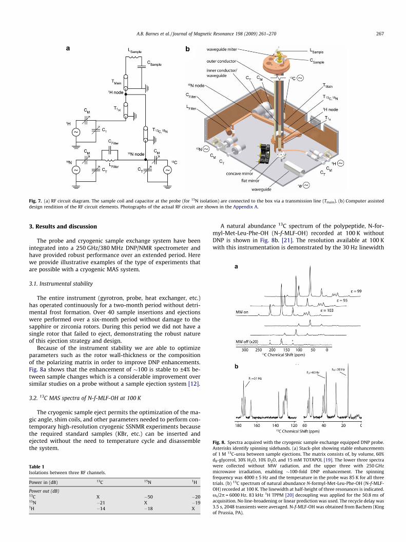
Fig. 8. Spectra acquired with the cryogenic sample exchange equipped DNP probe.Asterisks identify spinning sidebands. (a) Stack-plot showing stable enhancements
13
Fig. 7. (a) RF circuit diagram. The sample coil and capacitor at the probe (for 15N isolation) are connected to the box via a transmission line (Tmain). (b) Computer assisteddesign rendition of the RF circuit elements. Photographs of the actual RF circuit are shown in the Appendix A.
A.B. Barnes et al. / Journal of Magnetic Resonance 198 (2009) 261–270 267
3. Results and discussion
The probe and cryogenic sample exchange system have beenintegrated into a 250 GHz/380 MHz DNP/NMR spectrometer andhave provided robust performance over an extended period. Herewe provide illustrative examples of the type of experiments thatare possible with a cryogenic MAS system.
3.1. Instrumental stability
The entire instrument (gyrotron, probe, heat exchanger, etc.)has operated continuously for a two-month period without detri-mental frost formation. Over 40 sample insertions and ejectionswere performed over a six-month period without damage to thesapphire or zirconia rotors. During this period we did not have asingle rotor that failed to eject, demonstrating the robust natureof this ejection strategy and design.
Because of the instrument stability we are able to optimizeparameters such as the rotor wall-thickness or the compositionof the polarizing matrix in order to improve DNP enhancements.Fig. 8a shows that the enhancement of �100 is stable to ±4% be-tween sample changes which is a considerable improvement oversimilar studies on a probe without a sample ejection system [12].
3.2. 13C MAS spectra of N-f-MLF-OH at 100 K
The cryogenic sample eject permits the optimization of the ma-gic angle, shim coils, and other parameters needed to perform con-temporary high-resolution cryogenic SSNMR experiments becausethe required standard samples (KBr, etc.) can be inserted andejected without the need to temperature cycle and disassemblethe system.
Table 1Isolations between three RF channels.
Power in (dB) 13C 15N 1H
Power out (dB)13C X �50 �2015N �21 X �191H �14 �18 X
A natural abundance 13C spectrum of the polypeptide, N-for-myl-Met-Leu-Phe-OH (N-f-MLF-OH) recorded at 100 K withoutDNP is shown in Fig. 8b. [21]. The resolution available at 100 Kwith this instrumentation is demonstrated by the 30 Hz linewidth
of 1 M C-urea between sample ejections. The matrix consists of, by volume, 60%d8-glycerol, 30% H2O, 10% D2O, and 15 mM TOTAPOL [19]. The lower three spectrawere collected without MW radiation, and the upper three with 250 GHzmicrowave irradiation, enabling �100-fold DNP enhancement. The spinningfrequency was 4000 ± 5 Hz and the temperature in the probe was 85 K for all threetrials. (b) 13C spectrum of natural abundance N-formyl-Met-Leu-Phe-OH (N-f-MLF-OH) recorded at 100 K. The linewidth at half-height of three resonances is indicated.xr/2p = 6000 Hz. 83 kHz 1H TPPM [20] decoupling was applied for the 50.8 ms ofacquisition. No line-broadening or linear prediction was used. The recycle delay was3.5 s, 2048 transients were averaged. N-f-MLF-OH was obtained from Bachem (Kingof Prussia, PA).

Fig. 9. Chromophore in the active site of bacteriorhodopsin with a covalent Schiffbase linkage to Lys216. The retinylidene assumes a 13-cis, 15-syn conformation inbR555 and 13-trans, 15-anti in bR568. These conformers are named from theabsorption maximum in the UV–VIS spectrum; at 568 nm for bR568 and 555 nm inbR555.
Fig. 10. RFDR spectrum of [13C-14-retinal, 13Ce–Lys]: 15 mg of protein in 60 vol%d8-glycerol:40 vol% aqueous 0.3 M Guanadine.HCl (pH 10). xr/2p = 8000 Hz,temperature is 93 K at the stator, 32 indirect T1 points, spectrum recorded in 7.4 h.
268 A.B. Barnes et al. / Journal of Magnetic Resonance 198 (2009) 261–270
of the methionine–methyl peak. Furthermore, the data show reso-lution of signals from the 13C’s in the phenyl ring as its flipping rateentered the slow exchange regime near 100 K. The linewidths inthe aromatic region and of the central carbonyl in Fig. 8b(�51 Hz) demonstrate our ability to properly set the magic angleand shim at low temperature. The excellent resolution apparentin Fig. 8b suggests that, with proper attention to sample prepara-tion protocols, high resolution spectra of peptides and proteins atlow temperature should be attainable.
3.3. Distance measurements in the active site of bacteriorhodopsin
Bacteriorhodopsin (bR) is a 26 kDa light-driven ion pump thatestablishes an ion gradient across the cellular membrane of Halo-bacterium salinarium. In the active site of bR, a retinal co-factor iscovalently bound to the protein via a Schiff base linkage to Lysine216. At thermal equilibrium, bR exists as a 60:40 mixture of bR568
and bR555. The functional bR568 has a 13-trans, 15-anti retinylidenechromophore and bR555 has a 13-cis, 15-syn chromophore (Fig. 9).Detailed knowledge of the conformation around the C15@Nf bondat each stage of the bR photocycle is crucial to understanding theion translocation mechanism. For example, characterizing thetwist in the retinal polyene in the predischarge L state is importantin understanding the pump’s vectoriality.
Preliminary SSNMR studies suggest that double bond twist in Lis localized on the C15@N bond [6]. Here we use labeled 13C-14-retinal and 13Ce–Lys (see Fig. 9) in order to perform a standard
Fig. 11. Extraction of the 13C-14-retinal to 13Ce–Lys 216 distance in the active site of bbetween C14 and Ce in bR568 (red) and 3.11 Å in bR555 (black). The seven mixing pointconfidence interval of 3.90 ± 0.08 Å, and 11.7 ± 2.6 ms for bR568. (c) Similar contour plot f(For interpretation of color mentioned in this figure legend, the reader is referred to the
radio frequency driven recoupling (RFDR) [22] experiment. Accord-ingly, we determine the distance between the labeled sites, andthus the extent of isomerization around the C15@N bond. Althoughthis experiment was attempted some time ago in the absence ofDNP [23], only one mixing time was recorded due to low sensitiv-ity and instrument stability (the single 2D correlation spectrumtook �5 days to record). With DNP at 90 K, where the effectiveenhancement is �90, it required only 7.4 h to record a high quality2D spectrum (see Fig. 10) from 15 mg of protein even when theintensities of interest are divided into a roughly 60:40 ratio, corre-sponding to the populations of the two different intermediates.Consequently, we were able to acquire spectra with seven differentmixing times, providing reliable, quantitative data even whensmall amounts of sample are available.
acteriorhodopsin. (a) Least-squares fits of RFDR data yielding a distance of 3.90 Ås took a total of 52 h to record. (b) Residual sum of squares surface yielding a 95%or bR555, yielding 3.11 ± 0.22 Å, and 54.7 ± 19.2 ms for T2ZQ 95% confidence intervals.
web version of the article.)

A.B. Barnes et al. / Journal of Magnetic Resonance 198 (2009) 261–270 269
The recoupling build-up profiles yield distances of 3.11 ± 0.22 Åand 3.90 ± 0.08 Å between between C14 of retinal and Ce of Lys216in bR555 and bR568, respectively, corresponding well to the dis-tances of purely geometrical cis and trans conformations (3.1 and3.9 Å). The data were fit using the least-squares algorithm in SPIN-EVOLUTION, an NMR simulation package [24]. The random errorassociated with the measurements was also calculated using thesum of least squares function in the same software package; thecontour plots of which are shown in Fig. 11b and c.
Fig. A1. (a) Photograph of the probe. (b) The inside of the probe box showing the RF circubottom plate of the probe-box for coupling microwaves from the horizontal waveguide tDeceleration tube that gently stops the rotor during the ejection process.
4. Conclusions and outlook
We have designed and constructed a cryogenic, sample ex-change, MAS probe and successfully integrated it into a DNP/NMR spectrometer. The reliability of the system demonstratesthe robustness of the approach. The resulting system dramaticallyimproves experimental efficiency by eliminating the long periodsof time previously required for warming and cooling the probe tochange samples. Finally, while a cryogenic sample exchange sys-
it. (c) Top of the probe-box showing the seals to the probe-dewar. (d) Mirrors on theo the vertical waveguide. (e) Sample insertion chamber at the top of the magnet. (f)

270 A.B. Barnes et al. / Journal of Magnetic Resonance 198 (2009) 261–270
tem is advantageous for experiments performed at �85 K withnitrogen cryogens, this technology should prove even more valu-able at lower temperatures accessible with helium since the heatcapacity of He is lower and the corresponding warming/cooling cy-cles would be longer.
DNP has been shown effective at 5 and 9 Tesla, but its promiseresides in scaling of gyrotron technology and recent polarizationschemes to still higher fields[25,26] corresponding to 700–900 MHz. Movement of necessarily large and metallic probes insuch high magnetic fields generates eddy currents that decay overseveral hours. Since they are generated each time the probe is re-moved, a sample exchange system becomes even more desirableat higher magnetic fields.
Finally, in comparison to traditional NMR, DNP is well-suited forstudies of reaction intermediates. In particular, the cryogenic tem-peratures needed for DNP can also serve to trap reaction interme-diates, and provide the increase in sensitivity required toeffectively study mixtures of states. Maintaining a cryogenic tem-perature in the sample chamber during sample insertion permitsexperiments on flash-frozen samples. Although we have only gen-erated reaction intermediates of bacteriorhodopsin in situ [6], itshould be possible to flash freeze samples ex situ and withoutwarming insert them into the probe via the cryogenic sample ex-change system described here.
For these reasons we expect the instrumentation for sample ex-change at low temperatures described in this paper to play a sub-stantial role in applications of DNP to structural studies ofbiological solids.
Acknowledgments
This research was supported by the NIBIB through Grants EB-002804, EB-001960, EB-001035, EB-002026, and EB-003151.A.B.B. was supported through an NSF graduate research fellowshipand Y.M. acknowledges partial financial support from the NaitoFoundation. We thank Paul P. Woskov, Guo-Xing Miao, JagadeeshS. Moodera, Loren Andreas, Albert Smith and Thorsten Maly fortheir invaluable assistance and stimulating conversations duringthe course of this research.
Appendix A. Photographs of instrument
.
References
[1] A. Abragam, M. Goldman, Principles of dynamic nuclear polarisation, Rep. Prog.Phys. (1978) 395.
[2] T.R. Carver, C.P. Slichter, Polarization of nuclear spins in metals, Phys. Rev. 92(1953) 212.
[3] K.-N. Hu, H.-H. Yu, T.M. Swager, R.G. Griffin, Dynamic nuclear polarization withbiradicals, J. Am. Chem. Soc. 126 (2004) 10844–10845.
[4] T. Maly, G.T. Debelouchina, V.S. Bajaj, M.L. Mak-Jurkauskas, J.R. Sirigiri, K.-N.Hu, P.C.A. van der Wel, J. Herzfeld, R.J. Temkin, R.G. Griffin, Dynamic nuclearpolarization at high magnetic fields, J. Chem. Phys. 128 (2008) 052211.
[5] A.B. Barnes, G.d. Paepe, P.C.A. van der Wel, K.-N. Hu, C.-G. Joo, V.S. Bajaj, M.L.Mak-Jurkauskas, J.R. Sirigiri, J. Herzfeld, R.J. Temkin, R.G. Griffin, High fielddynamic nuclear polarization for solid and solution biological NMR, Appl.Magn. Reson. 34 (2008) 237–263.
[6] M.L. Mak-Jurkauskas, V.S. Bajaj, M.K. Hornstein, M. Belenky, R.J. Temkin, R.G.Griffin, J. Herzfeld, Energy transformations early in the bacteriorhodopsinphotocycle revealed by DNP-enhanced solid state NMR, Proc. Natl. Acad. Sci.USA 105 (2008) 883–888.
[7] T. Maly, Personal Communication, Massachusetts Institute of Technology,2008.
[8] P.C.A. van der Wel, K.-N. Hu, J.R. Lewandowski, R.G. Griffin, Dynamic nuclearpolarization of amyloidogenic peptide nanocrystals: GNNQQNY, a coresegment of the yeast prion protein sup35p, J. Am. Chem. Soc. 128 (2006)10840–10846.
[9] V.S. Bajaj, M.K. Hornstein, K.E. Kreischer, J.R. Sirigiri, P.P. Woskov, M. Mak, J.Herzfeld, R.J. Temkin, R.G. Griffin, 250 GHz gyrotron for dynamic nuclearpolarization in biological solid state NMR, J. Magn. Reson. 190 (2007) 86–114.
[10] K.E. Kreischer, C. Farrar, R.G. Griffin, R.J. Temkin, J. Vieregg, Development of a250 GHz CW gyrotron for EPR and NMR spectroscopy, in: L. Lombardo (Ed.),Proceedings of the 24th International Conference on Infrared and MillimeterWaves, UC Davis, Monterey, CA, 1999, pp. TU–A3.
[11] P.J. Allen, F. Creuzet, H.J.M. de Groott, R.G. Griffin, Apparatus for low-temperature magic-angle spinning NMR, J. Magn. Reson. 92 (1991) 614–617.
[12] Y. Masuki, Personal Communication, Massachusetts Institute of Technology,2008.
[13] K.R. Thurber, R. Tycko, Biomolecular solid state NMR with magic-anglespinning at 25 K, J. Magn. Reson. 195 (2008) 179–186.
[14] J.G.I. Weisend, Handbook of Cryogenic Engineering, Taylor & Francis,Philadelphia, 1998.
[15] M.J. Dickson, D. Green, The cold-rolling and primary-recrystallisation texturesof 18% chromium steels containing 10%, 12%, and 14% Nickel, Mater. Sci. Eng. 4(1969) 304–312.
[16] P.W. Woskov, V.S. Bajaj, M.K. Hornstein, R.J. Temkin, R.G. Griffin, Corrugatedwaveguide and directional coupler for CW 250 GHz gyrotron DNPexperiments, IEEE Trans. Microw. Theory Tech. 53 (2005) 1863–1869.
[17] R.A. McKay, Probes for special purposes, in: D.M. Grant, R. Harris (Eds.),Encyclopedia of Nuclear Magnetic Resonance, John Wiley and Sons, New York,1996, pp. 3768–3771.
[18] V.S. Bajaj, Dynamic Nuclear Polarization in Biomolecular Solid State NMR:Methods and Applications in Peptides and Membrane Proteins, MassachusettsInstitute of Technology (M. I. T.), 2007.
[19] C. Song, K.-N. Hu, T.M. Swager, R.G. Griffin, TOTAPOL—a biradical polarizingagent for dynamic nuclear polarization experiments in aqueous media, J. Am.Chem. Soc. 128 (2006) 11385–11390.
[20] A.E. Bennett, C.M. Rienstra, M. Auger, K.V. Lakshmi, R.G. Griffin, Heteronucleardecoupling in rotating solids, J. Chem. Phys. 103 (1995) 6951.
[21] V.S. Bajaj, P.C.A. van der Wel, R.G. Griffin, Observation of a low-temperature,dynamically driven, structural transition in a polypeptide by solid state NMRspectroscopy, J. Am. Chem. Soc. 131 (2009) 118–128.
[22] A.E. Bennett, C.M. Rienstra, J.M. Griffiths, W.G. Zhen, P.T. Lansbury, R.G. Griffin,Homonuclear radio frequency—driven recoupling in rotating solids, J. Chem.Phys. 108 (1998) 9463–9479.
[23] J.M. Griffiths, K.V. Lakshmi, A.E. Bennett, J. Raap, C.M. Vanderwielen, J.Lugtenburg, J. Herzfeld, R.G. Griffin, Dipolar correlation NMR-spectroscopy ofa membrane-protein, J. Am. Chem. Soc. 116 (1994) 10178–10181.
[24] M. Veshtort, R.G. Griffin, SPINEVOLUTION: a powerful tool for simulations ofsolid and liquid state NMR experiments, J. Magn. Reson. 178 (2006) 248–282.
[25] V. Weis, R.G. Griffin, Electron nuclear cross polarization, Solid State Nucl. Mag.Reson. 29 (2006) 105–117.
[26] K.-N. Hu, C. Song, H.-h. Yu, T.M. Swager, R.G. Griffin, High-frequency dynamicnuclear polarization using biradicals: a multifrequency EPR lineshape analysis,J. Chem. Phys. 128 (2008) 052302.