journal of rock mechanics and geotechnical engineering · p. jain et al. / journal of rock...
TRANSCRIPT

Pr
Pa
b
a
ARRA
KTORGD
1
cbtsbasmpb
PA
1Sh
Journal of Rock Mechanics and Geotechnical Engineering 6 (2014) 36–47
Journal of Rock Mechanics and Geotechnical Engineering
Journal of Rock Mechanics and GeotechnicalEngineering
j ourna l ho mepage: www.rockgeotech.org
erformance characteristics of tunnel boring machine in basalt and pyroclasticocks of Deccan traps – A case study
rasnna Jaina, A.K. Naithania, T.N. Singhb,∗
National Institute of Rock Mechanics (NIRM), Kolar Gold Fields, Karnataka, IndiaIndian Institute of Technology, Mumbai, India
r t i c l e i n f o
rticle history:eceived 6 May 2013eceived in revised form 16 October 2013ccepted 28 November 2013
eywords:unnelingpen-type tunnel boring machine (TBM)ock mass classificationround supporting
a b s t r a c t
A 12.24 km long tunnel between Maroshi and Ruparel College is being excavated by tunnel boring machine(TBM) to improve the water supply system of Greater Mumbai, India. In this paper, attempt has beenmade to establish the relationship between various litho-units of Deccan traps, stability of tunnel andTBM performances during the construction of 5.83 km long tunnel between Maroshi and Vakola. TheMaroshi–Vakola tunnel passes under the Mumbai Airport and crosses both runways with an overburdencover of around 70 m. The tunneling work was carried out without disturbance to the ground. The rocktypes encountered during excavation are fine compacted basalt, porphyritic basalt, amygdaloidal basalt,pyroclastic rocks with layers of red boles and intertrappean beds consisting of various types of shales.Relations between rock mass properties, physico-mechanical properties, TBM specifications and the cor-
eccan trap responding TBM performance were established. A number of support systems installed in the tunnelduring excavation were also discussed. The aim of this paper is to establish, with appropriate accuracy,the nature of subsurface rock mass condition and to study how it will react to or behave during under-ground excavation by TBM. The experiences gained from this project will increase the ability to cope withunexpected ground conditions during tunneling using TBM.
and
fatvgdhwAwhiwc
© 2013 Institute of Rock
. Introduction
The Brihanmumbai Municipal Corporation (BMC) has decided tohange all surface water pipelines and to create subsurface systemsy constructing tunnels to avoid problems of leakage, unconven-ional loss and also to protect water from contamination. The waterupply systems through surface pipelines in Mumbai are age-old,uilt for more than 70 years. These supply systems leak frequentlynd need repeated maintenance. All these pipes are highly pres-urized and badly encroached by the population, which makesaintenance difficult. In Maroshi and Vakola sections, these pipes
ass below the runways of Mumbai Airport and in case of strongurst it will affect the ground below the runways. The decision
∗ Corresponding author. Tel.: +91 22 2576 7271; fax: +91 22 2576 7253.E-mail address: [email protected] (T.N. Singh).
eer review under responsibility of Institute of Rock and Soil Mechanics, Chinesecademy of Sciences.
Production and hosting by ElsevierELSEVIER
674-7755 © 2013 Institute of Rock and Soil Mechanics, Chinese Academy ofciences. Production and hosting by Elsevier B.V. All rights reserved.ttp://dx.doi.org/10.1016/j.jrmge.2013.11.003
c
MMnllaCihs
Soil Mechanics, Chinese Academy of Sciences. Production and hosting byElsevier B.V. All rights reserved.
or the construction of tunnels was made because tunnels havedvantages of low maintenance and less security accident. Withhe development of tunneling technology, it is possible to exca-ate tunnels with tunnel boring machine (TBM) under favorableround conditions instead of adopting conventional methods likerill-and-blast method. For the Mumbai water supply scheme, aard rock TBM was deployed earlier in 1984 and a tunnel of 3.87 kmas driven with 3.5 m diameter gripper type TBM (Tribune no-ITA-ITES). The tunnel was reported successfully excavated in 450 daysith a best monthly advance of 376 m. Construction of the tunnelsas improved substantially the distribution of water supply system
n Mumbai, which is an effective manner. Prior to these projects,orldwide experiences in driving tunnel through basalts and pyro-
lastics rocks with full-face were limited. The present scheme is aontinuation to those successful efforts.
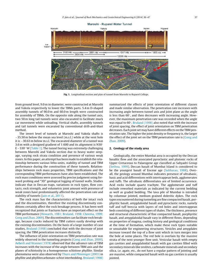
To improve the water supply to Vakola, Mahim, Dadar andalbar Hill of Greater Mumbai, a 12.24 km long tunnel betweenaroshi and Ruparel College is being excavated by TBM. The tun-
el is divided into three sections, i.e. Maroshi–Vakola (5.834 kmong), Vakola–Mahim (4.549 km long) and Mahim–Ruparel Col-ege (1.859 km long) (Fig. 1). The longest tunnel between Maroshind Vakola has been completed. A vent hole of 30 cm diameter at
hainage 3230 m at Maroshi–Vakola section was drilled for releas-ng pressure. For constructing tunnels from Maroshi to the ventole and from Vakola to the vent hole, vertical shafts were con-tructed at either end. The inlet shafts of 82.0 m and 68.0 m in depth
P. Jain et al. / Journal of Rock Mechanics and Geotechnical Engineering 6 (2014) 36–47 37
of tun
faaftcam
−i3Ebaztpscrwitws
adrTGatss
wAippp
saiiewodetZ
2
bU(babaAiabtptbaboaoitsg
Fig. 1. Longitudinal section and plan
rom ground level, 9.0 m in diameter, were constructed at Maroshind Vakola respectively to lower the TBMs parts. 5.4 m D-shapedssembly tunnels of 90.0 m and 60.0 m length were constructedor assembly of TBMs. On the opposite side along the tunnel axis,wo 50 m long tail tunnels were also excavated to facilitate muckar movement while unloading. Vertical shafts, assembly tunnelsnd tail tunnels were excavated by conventional drill-and-blastethod.The invert level of tunnels at Maroshi and Vakola shafts is
35.50 m below the mean sea level (m.s.l.) while at the vent holet is −30.63 m below m.s.l. The excavated diameter of a tunnel was.6 m with a designed gradient of 1:600 and its alignment is N30◦
– S30◦ W (Table 1). The tunnel boring was extremely challengingetween Maroshi and Vakola section due to heavy water seep-ge, varying rock strata condition and presence of various weakones. In this paper, an attempt has been made to establish the rela-ionship between various litho-units, stability of tunnel and TBMerformance during the construction of these tunnels. Relation-hips between rock mass properties, TBM specifications and theorresponding TBM performances have also been established. Theock mass conditions were assessed by precise judgment using for-ard probing and “3D” geological logging of tunnel walls. Studies
ndicate that in Deccan traps, variations in rock types, flow con-acts, rock strength, and volumetric joint amount with presence ofeak zones have predominantly affected the penetration rate and
tability of tunnels (Jain et al., 2011).The rock mass has the characteristics of both the intact rock
nd the discontinuities, therefore the existing discontinuity con-itions certainly affect the rock breakage process. It has been wellecognized that joints or fractures have an important effect on theBM performance (Howarth, 1981; Bruland, 1998; Cheema, 1999;ong and Zhao, 2009). The discontinuities can facilitate rock break-ge, because cracks induced by TBM cutters easily develop withhe existing discontinuities. On the basis of a large number of casetudies, Bruland (1998) concluded that with the decrease of jointpacing, the TBM penetration increases distinctly.
The influence of joint orientation on TBM penetration rate wasidely observed in the tunneling projects (Gong and Zhao, 2009).eberli and Wanner (1978) observed that the advance rate of TBM
ncreases with the increase of the angle between TBM axis and thelanes of schistosity in a homogeneous schistose phyllite. Similarhenomena were also observed by Thuro and Plinninger (2003) inhyllite and phyllitecarbonate-schist interbedding. Bruland (1998)
ssaj
nel from Maroshi to Ruparel College.
ummarized the effects of joint orientation of different classesnd made similar observation. The penetration rate increases withncreasing angle between tunnel axis and joint plane as the angles less than 60◦, and then decreases with increasing angle. How-ver, the maximum penetration rate was recorded when the angleas equal to 60◦. Bruland (1998) also noted that with the increase
f joint spacing, the effect of joint orientation on TBM penetrationecreases. Each joint set may have different effects on the TBM pen-tration rate. The higher the joint density or frequency is, the largerhe effect of the joint set on the TBM penetration rate is (Gong andhao, 2009).
. Geology of the study area
Geologically, the entire Mumbai area is occupied by the Deccanasaltic flow and the associated pyroclastic and plutonic rocks ofpper Cretaceous to Palaeogene age classified as Sahyadri Group
Sethna, 1999). Deccan basalt of Mumbai Island is considered toe the youngest basalt of Eocene age (Subbarao, 1988). Over-ll, the geology around Mumbai indicates presence of ultrabasic,asic and acid differentions with intertrappean beds, agglomeratesnd tuffs. The ultrabasic differentiates are of limited occurrence.cid rocks include quartz trachyte. The agglomerate and tuff
nclude reworked materials as indicated by the current beddings well as graded bedding. The lava pile of Mumbai is intrudedy columnar jointed, medium grained doleritic dykes. The rockypes encountered during tunneling are fine compacted basalt, por-hyritic basalt, amygdaloidal basalt and pyroclastic rocks, namelyuff and tuff breccia with layers of red boles and intertrappeaneds consisting of different types of shales. The thickness, presencend structural characteristic of fine compacted basalt, porphyriticasalt, and amygdaloidal basalt vary in different flows, dependingn properties of magma, cooling history and geological conditionst the time of formation, which make these rock types suitabler unsuitable for engineering structures. Vesicles and amygdalesncrease toward the top of a flow unit which in turn merges intohe bole at some places. The red bole is overlain by the massivetrata of the next younger flow unit. Vesicular basalt with emptyas cavities and amygdaloidal basalt with gas cavities filled with
econdary minerals like zeolites, carbonate minerals and secondaryilica, i.e. agate, etc., do not have a regular pattern of jointing andre massive, while compacted basalt with no gas cavities is usuallyointed.
38 P. Jain et al. / Journal of Rock Mechanics and Geotechnical Engineering 6 (2014) 36–47
Table 1Salient features of Maroshi–vent hole and Vakola–vent hole tunnels.
Tunnels Tunnel boringlength (m)
Shape Excavated diameter(bore section) (m)
Finisheddiameter (m)
Excavationquantity (m3/m)
Volume (totalexcavation) (m3)
Lining (reinforcedcement concrete,RCC)-grade andthickness
Concrete quantity(m3/m)
Maroshi–vent hole 3086.34 Circular 3.6 3.0 10.18 31,419 Total lined: M-20 and300 mm
3.11
Vakola–vent hole 2590.4 Circular 3.6 3.0 10.18 26,370 Total lined: M-20 and300 mm
3.11
Tunnels Boring startdate
Boring completiondate
Tunnel boringduration (month)
Monthly averagetunnel boring progress(m)
Maximum progressper month(m/month)
Daily average tunnelboring progress (m/d)
Maximum boringprogress in one day(m/d)
Maroshi–vent 27 Dec. 2008 26 Sep. 2009 9 339.16 542.6 13.57 29.5
fwaooiwspobcaw
titeafleiecatdlfflo
ajtcapfiGbtzta
wmtwio
ea((ateobgTor
3
vrrmsa3lsutaom
4
T
holeVakola–vent
hole7 Nov. 2008 10 Aug. 2009 9 281.57
The lava flows show various types of structures such as joints,ractures, vesicles, veins, breccias clasts, mafic-dykes and amygduleith different shapes like circular, elliptical and irregular bound-
ry. Due to the emplacement of the traps upon the eroded surfacesf the earlier rock strata, minor undulations in the flow were alsobserved. The general flows contact dip varies between 30◦ and 45◦
n N020◦–N040◦ and N200◦–N220◦ directions. Some flow contactsere open, filled with weathered, altered or soft materials while
ome were tight and commonly coalescent. Open flow contactsrovide passage for water and weathered materials. Weatheredr soft materials are generally deposited during the time internaletween two flows. The angle between the tunnel axis and the flowontact was 80◦ and penetration rate was less at flow contact. Thedvance rate was low in case of open flow contact zones while itas high in tight flow contact zones.
The sequences of flows are different in different chainages ofunnel indicating they do not have regular structure like ideal sed-mentary rocks. In sedimentary rocks, beds having plane surfacesops and bottoms, constant dip, uniform thickness and wide lateralxtent, such a disparity in sequences could validly be interpreteds a fault. It has now been well established that Deccan trap basaltows do not have such regular structure, and have limited the lat-ral extent and stretch out over short distances. There is variationn thicknesses, i.e. flows usually have different thickness in differ-nt parts. Its tops and bottoms are not regular plane surfaces withonstant dip but irregular surfaces. As a result, it is almost invari-ble that flow sequence in boreholes, which were drilled duringhe investigation does not normally match. This disparity howeveroes not indicate faulting as it would be in case of beds with regu-
ar structural behavior. Hence, the possibility of the occurrence of aault between boreholes need not be apprehended merely becauseow sequence in boreholes does not match, as this disparity is theutcome of the structural irregularity of the basalt flows.
Traps show two or more sets of vertical joints. Horizontal jointsre parallel to the top or bottom surfaces. Two sets of columnaroints were observed in thicker flows. Fractures were identified andhey were generally parallel to the prominent joint directions. Con-hoidal fracturing of rock mass was a common feature. Generally,mygdaloidal basalt and tuff breccia were massive while in por-hyritic basalt the spacing of joint sets was more than 2 m and inne grained jointed compacted basalt it varied from 10 cm to 30 cm.enerally, TBM penetration rate was greater in fine compactedasalt than that in the porphyritic basalt. Veins are extension frac-
ure that was filled with mineral deposits of quartz, calcite andeolites of different dimensions. They were generally sheet like orabular or regular in shape. Veins have major influences on cav-bility and fragmentation and may be weaker or stronger than thesrtr
474.4 11.26 39.9
all rock. In the tunnels, generally, calcite and zeolite veins wereapped. About 32 cm to 3.5 m thick mafic dykes were mapped in
he Vakola shaft area. The dyke exhibits prominent columnar joints,hich were formed due to differential volume changes in cool-
ng and contracting magma. No curviplanar (fold) structure wasbserved during the geological “3D” logging of the tunnel wall.
The mineralogical content of basaltic rocks was analyzed forach rock type. Major mineral composition of fine grained basaltnd porphyritic basalt constitutes plagioclase (40–45%), pyroxene15–20%), glass (10–15%), iron oxide (8–10%), and secondary calcite7–10%), and groundmass was composed of plagioclase, pyroxenend glass. The mineral contents of the amygdaloidal basalt anduff breccia are plagioclase (35%), devitrified glass (30%), pyrox-ne (20%), and oxide phase (15%), and groundmass was composedf glass, chlorite, calcite and zeolite. Cutter abrasion in basalts andreccia was less due to less quartz and low silica percentage. Basaltenerally has a composition of SiO2 (45–55%), total alkalis (2–6%),iO2 (0.5–2%), FeO (5–14%) and Al2O3 (14% or more). The contentf CaO is commonly about 10% and that of MgO is usually in theange of 5–12%.
. TBM specifications
WIRTH TB-II-320H and TB-II-360H TBMs were used for the exca-ation of Maroshi–vent hole and Vakola–vent hole tunnel sectionsespectively. These are refurbished full face hard rock TBMs andefurbishment was carried out under supervision of equipmentanufacturer. TBMs were previously used in earlier projects with
imilar bore diameter. TB-II-320H TBM has done 4.5 km boringt previous project and was idle at workshop for 3 years. TB-II-60H TBM has done 7.5 km boring at earlier project and was also
ying at workshop for 3 years before used at this project site. TBMspecifications collected from the documents provided by the man-facturer are given in Table 2. The operating parameters includinghrust force, torque and rotation per minute (RPM) of the machinere important for understanding the effect of geological conditionsn the machine performance and for penetration rate measure-ent.
. Physico-mechanical properties of rocks
The rock strength is directly related to the performance ofBM. Uniaxial compressive strength (UCS) and Brazilian tensile
trength tests were performed in accordance with the procedureecommended by ISRM (Brown, 1981). These are the parameterso evaluate the rock mass boreability. Laboratory rock strength testesults of core samples are given in Table 3.
P. Jain et al. / Journal of Rock Mechanics and Geotechnical Engineering 6 (2014) 36–47 39
Table 2Principal specifications of TBMs employed in Maroshi–Vakola sections.
Tunnel sections TBM model Type Input supply(kV)
Cutter headdiameter (m)
Cutter numbers Cutter diskdiameter (mm)
Cutter spacing(mm)
No. of buckets
Maroshi–vent hole WIRTHTB-II-320H
Hard rock,open type
11 3.6 31 (center cutters-6;face cutters-17;pregauge cutters-5;gauge cutters-3)
432 62 5
Vakola–vent hole WIRTHTB-II-360H
Hard rock,open type
6.6 3.6 31 (center cutters-6;face cutters-17;pregauge cutters-5;gauge cutters-3)
432 62 5
Tunnel sections No. of scrapers Cutter headspeed (rpm)
Cutter head torque(maximum) (bar)
Cutter head thrust(maximum) (bar)
Stroke (mm) Muck handlingcapacity (m/h)
Estimated weight (t)
Maroshi–vent hole 2 × 5 sets = 10scraper plates
0–14 225 220 1100 5 107
Vakola–vent hole 3 × 5 sets = 15scraper plates
0–12 185 220 1100 5 107
Table 3Laboratory rock strength results of core samples.
Rock type RQD (%) UCS (MPa) Point load test (Is50, MPa) Brazilian tensilestrength (MPa)
Brittleness index
Range Average Range Average Range Average Range Average
Fine compact basalt 30–90 33.35–115.90 78.20 – – 2.57–13.31 9.46 8.26–15.12 8.26Porphyritic basalt 90–100 115.87–143.33 130.60 – – 8.76–15.26 13.28 8.31–15.78 9.83Amygdaloidal basalt 95–100 54.10–65.70 59.80 – – – – – –Tuff breccia 95–100 26.43–50.20 34.46 1.33–3.44 2.38 1.5–3.2 2.35 4.60–11.5 14.48Tuff 95–100 15.68–24.28 18.40 0.5–1.25 0.87 1.6–3.8 2.7 4.12–15.17 6.8
–
–
rrtspi1at1Oi2t
fobatitGto
5
iit
VFrRtSIsgmgl3rowGtomwr
twd(tn
Flow contact zone 40–60 12.40–31.87 14.60
Intertrappeans (shale) 45–75 28.30–34.35 31.32
UCS is one of the most important rock strength parameters forock mass condition evaluation and is commonly used to assessock mass boreability. It has been proved that when the rolling cut-er indents the rock, the stress exerted must be higher than the rocktrength. The rock strength affects the rock behavior under com-ression. During the excavation of tunnels, the penetration rate
s distributed in a large range from about 2 mm/rev to more than2 mm/rev due to the effect of UCS. A loading rate of 200 N/s wasdopted. Some models for predicting penetration rate show thathe penetration rate is directly associated with rock UCS (Graham,976; Farmer and Glossop, 1980; Rostami and Ozdemir, 1993;’Rourke et al., 1994). The penetration rate decreases as the UCS
ncreases, for example, the penetration rate is about 6.3 m/h at5 MPa of the rock UCS, and 1.9 m/h at 105 MPa of UCS. Generally,he penetration rate and UCS show a linear relationship.
Brittleness index is another parameter to understand the per-ormance of TBM. The rock brittleness index is defined as the ratiof rock compressive strength to tensile strength. The effect of rockrittleness index on TBM penetration process was studied by Gongnd Zhao (2007). The result shows that with increasing rock brit-leness index, the cutter indentation process gets easier. Cutterndentation means the rolling cutter intrudes into the rock, andhen generates small and large fragments as well as internal cracks.enerally, the penetration rate increases with increasing rock brit-
leness index but there is not a linear relation due to the effects ofther rock mass parameters like jointing pattern in the rock mass.
. Assessment of rock mass
A detailed engineering geological investigation was carried outn the tunnels to acquire the geological and/or geotechnical details,.e. rock description, rock discontinuity orientation and descrip-ion, groundwater condition, etc., for rock mass quality assessment.
ptti
– – – – –– 4.90–6.10 5.50 4.63–7.10 5.70
arious rock types encountered during tunneling are illustrated inigs. 2 and 3. Some researchers have correlated TBM performance toock mass classification systems using RSR (rock structure rating),MR (rock mass rating), Q-system and IMS (integrated mass sys-em) (Innaurato et al., 1991; McFeat-Smith and Broomfield, 1997;undaram et al., 1998; Sapigni et al., 2002; Hamidi et al., 2010).n this project, the rock mass was characterized using RMR clas-ifications (Bieniawski, 1989). RMR values were calculated aftereological mapping and measurements of discontinuity data. Rockass classification for different litho-units of tunnel sections are
iven in Figs. 4 and 5. In the Maroshi–vent hole section, 1160 mength fell in good rock mass category, while 1098.5 m, 453 m and75 m lengths fell in fair, very good and poor rock mass categoriesespectively. In the Vakola–vent hole section, 1510.5 m length wasf good rock mass category, while 998 m, 60 m and 22 m lengthsere of fair, very good and poor rock mass categories respectively.enerally, the rock conditions were fair to good except at or near
he flow contacts where poor to fair rock mass conditions werebserved. For medium quality rock masses (RMR of 40–75), theaximum TBM performances (penetration rate and advance rate)ere achieved while lower penetration was for poor and very good
ock masses.Based on petrographic, textural and structural characteristics,
heir engineering properties and RMR, the tunneling rock mediaere classified into three main categories, i.e. basalts (amyg-aloidal basalt/compacted basalt/porphyritic basalt), pyroclasticstuff/tuff breccia) and intertrappeans (shaly material), to assessheir behaviors and the performances of TBM. The different diag-ostic engineering properties of amygdaloidal, compacted and
orphyritic basalts lie in the degree and pattern of jointing. Inhis area, commonly basalts were transitional between these threeypes. About 62.25%, i.e. 3534 m length, of the tunnel was excavatedn basalts (compacted basalt-3341 m, porphyritic basalt-193 m).
40 P. Jain et al. / Journal of Rock Mechanics and Geotechnical Engineering 6 (2014) 36–47
Fig. 2. Lithological mapping along tunnel from Maroshi to vent hole (Ch. 90–3180 m).
Fig. 3. Lithological mapping along tunnel from Vakola to vent hole (Ch. 57–2645 m).
-20
0
20
40
60
80
100
90 to
93
93 to
94
94 to
148
148
to 1
5715
7 to
163
163
to 1
7517
5 to
185
185
to 1
9519
5 to
208
208
to 2
0920
9 to
535
535
to 5
6556
5 to
582
582
to 5
9759
7 to
720
720
to 7
2872
8 to
759
759
to 7
6076
0 to
777
777
to 7
8278
2 to
849
849
to 8
5185
1 to
865
865
to 8
6786
7 to
975
975
to 9
8098
0 to
101
210
12 to
101
310
13 to
101
910
19 to
102
010
20 to
115
711
57 to
116
011
60 to
118
011
80 to
118
911
89 to
119
111
91 to
121
012
10 to
128
912
20 to
122
412
24 to
124
912
49 to
128
912
89 to
129
512
95 to
136
013
60 to
136
913
69 to
178
717
87 to
181
618
16 to
193
819
38 to
194
119
41 to
194
919
49 to
195
219
52 to
199
419
94 to
200
320
03 to
203
620
36 to
206
620
66 to
210
521
05 to
215
021
50 to
221
022
10 to
229
422
94 to
230
223
02 to
231
623
16 to
232
023
20 to
232
623
26 to
233
723
37 to
234
523
45 to
241
524
15 to
244
824
48 to
247
124
71 to
252
925
29 to
253
625
36 to
255
525
55 to
261
026
10 to
265
926
59 to
267
226
64 to
266
726
67 to
278
227
82 to
315
131
51 to
316
231
62 to
317
7
RM
R R
atin
g s &
Val
ue
Chainage in metres
UCS RQD Spacing Discontinuity Conditions Ground water Orientation RMR
Fig. 4. RMR rating at different chainage
s along Marosh–vent hole tunnel.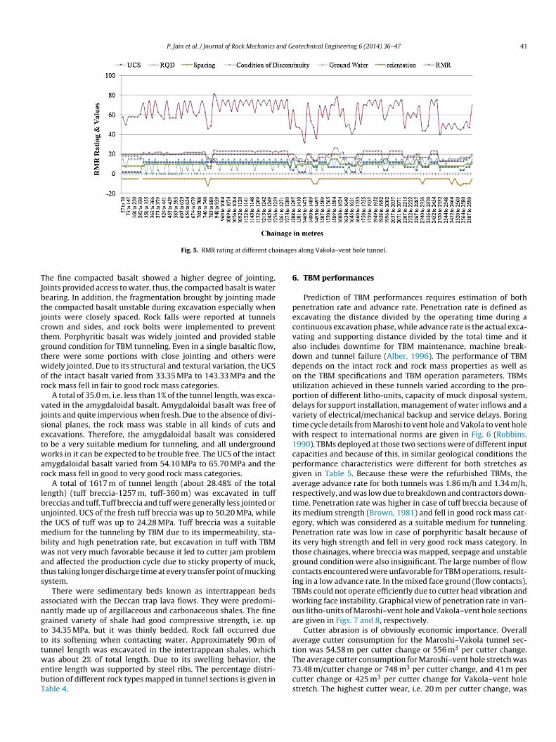
P. Jain et al. / Journal of Rock Mechanics and Geotechnical Engineering 6 (2014) 36–47 41
inage
TJbtjctgtwor
vjsetwar
lbutmbwats
angtttwebT
6
pecvaddoupdvtw1cpgartiePitgciTwoa
at
Fig. 5. RMR rating at different cha
he fine compacted basalt showed a higher degree of jointing.oints provided access to water, thus, the compacted basalt is waterearing. In addition, the fragmentation brought by jointing madehe compacted basalt unstable during excavation especially whenoints were closely spaced. Rock falls were reported at tunnelsrown and sides, and rock bolts were implemented to preventhem. Porphyritic basalt was widely jointed and provided stableround condition for TBM tunneling. Even in a single basaltic flow,here were some portions with close jointing and others wereidely jointed. Due to its structural and textural variation, the UCS
f the intact basalt varied from 33.35 MPa to 143.33 MPa and theock mass fell in fair to good rock mass categories.
A total of 35.0 m, i.e. less than 1% of the tunnel length, was exca-ated in the amygdaloidal basalt. Amygdaloidal basalt was free ofoints and quite impervious when fresh. Due to the absence of divi-ional planes, the rock mass was stable in all kinds of cuts andxcavations. Therefore, the amygdaloidal basalt was consideredo be a very suitable medium for tunneling, and all undergroundorks in it can be expected to be trouble free. The UCS of the intact
mygdaloidal basalt varied from 54.10 MPa to 65.70 MPa and theock mass fell in good to very good rock mass categories.
A total of 1617 m of tunnel length (about 28.48% of the totalength) (tuff breccia-1257 m, tuff-360 m) was excavated in tuffreccias and tuff. Tuff breccia and tuff were generally less jointed ornjointed. UCS of the fresh tuff breccia was up to 50.20 MPa, whilehe UCS of tuff was up to 24.28 MPa. Tuff breccia was a suitable
edium for the tunneling by TBM due to its impermeability, sta-ility and high penetration rate, but excavation in tuff with TBMas not very much favorable because it led to cutter jam problem
nd affected the production cycle due to sticky property of muck,hus taking longer discharge time at every transfer point of muckingystem.
There were sedimentary beds known as intertrappean bedsssociated with the Deccan trap lava flows. They were predomi-antly made up of argillaceous and carbonaceous shales. The finerained variety of shale had good compressive strength, i.e. upo 34.35 MPa, but it was thinly bedded. Rock fall occurred dueo its softening when contacting water. Approximately 90 m ofunnel length was excavated in the intertrappean shales, which
as about 2% of total length. Due to its swelling behavior, thentire length was supported by steel ribs. The percentage distri-ution of different rock types mapped in tunnel sections is given inable 4.
T7cs
s along Vakola–vent hole tunnel.
. TBM performances
Prediction of TBM performances requires estimation of bothenetration rate and advance rate. Penetration rate is defined asxcavating the distance divided by the operating time during aontinuous excavation phase, while advance rate is the actual exca-ating and supporting distance divided by the total time and itlso includes downtime for TBM maintenance, machine break-own and tunnel failure (Alber, 1996). The performance of TBMepends on the intact rock and rock mass properties as well asn the TBM specifications and TBM operation parameters. TBMstilization achieved in these tunnels varied according to the pro-ortion of different litho-units, capacity of muck disposal system,elays for support installation, management of water inflows and aariety of electrical/mechanical backup and service delays. Boringime cycle details from Maroshi to vent hole and Vakola to vent holeith respect to international norms are given in Fig. 6 (Robbins,
990). TBMs deployed at those two sections were of different inputapacities and because of this, in similar geological conditions theerformance characteristics were different for both stretches asiven in Table 5. Because these were the refurbished TBMs, theverage advance rate for both tunnels was 1.86 m/h and 1.34 m/h,espectively, and was low due to breakdown and contractors down-ime. Penetration rate was higher in case of tuff breccia because ofts medium strength (Brown, 1981) and fell in good rock mass cat-gory, which was considered as a suitable medium for tunneling.enetration rate was low in case of porphyritic basalt because ofts very high strength and fell in very good rock mass category. Inhose chainages, where breccia was mapped, seepage and unstableround condition were also insignificant. The large number of flowontacts encountered were unfavorable for TBM operations, result-ng in a low advance rate. In the mixed face ground (flow contacts),BMs could not operate efficiently due to cutter head vibration andorking face instability. Graphical view of penetration rate in vari-
us litho-units of Maroshi–vent hole and Vakola–vent hole sectionsre given in Figs. 7 and 8, respectively.
Cutter abrasion is of obviously economic importance. Overallverage cutter consumption for the Maroshi–Vakola tunnel sec-ion was 54.58 m per cutter change or 556 m3 per cutter change.
he average cutter consumption for Maroshi–vent hole stretch was3.48 m/cutter change or 748 m3 per cutter change, and 41 m perutter change or 425 m3 per cutter change for Vakola–vent holetretch. The highest cutter wear, i.e. 20 m per cutter change, was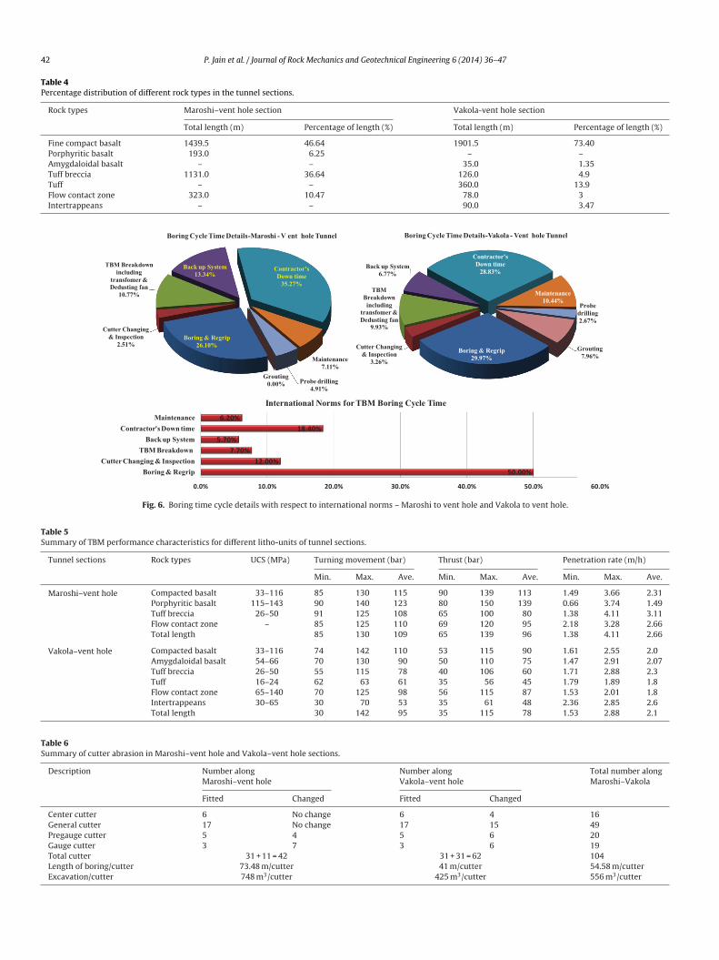
42 P. Jain et al. / Journal of Rock Mechanics and Geotechnical Engineering 6 (2014) 36–47
Table 4Percentage distribution of different rock types in the tunnel sections.
Rock types Maroshi–vent hole section Vakola-vent hole section
Total length (m) Percentage of length (%) Total length (m) Percentage of length (%)
Fine compact basalt 1439.5 46.64 1901.5 73.40Porphyritic basalt 193.0 6.25 – –Amygdaloidal basalt – – 35.0 1.35Tuff breccia 1131.0 36.64 126.0 4.9Tuff – – 360.0 13.9Flow contact zone 323.0 10.47 78.0 3Intertrappeans – – 90.0 3.47
Fig. 6. Boring time cycle details with respect to international norms – Maroshi to vent hole and Vakola to vent hole.
Table 5Summary of TBM performance characteristics for different litho-units of tunnel sections.
Tunnel sections Rock types UCS (MPa) Turning movement (bar) Thrust (bar) Penetration rate (m/h)
Min. Max. Ave. Min. Max. Ave. Min. Max. Ave.
Maroshi–vent hole Compacted basalt 33–116 85 130 115 90 139 113 1.49 3.66 2.31Porphyritic basalt 115–143 90 140 123 80 150 139 0.66 3.74 1.49Tuff breccia 26–50 91 125 108 65 100 80 1.38 4.11 3.11Flow contact zone – 85 125 110 69 120 95 2.18 3.28 2.66Total length 85 130 109 65 139 96 1.38 4.11 2.66
Vakola–vent hole Compacted basalt 33–116 74 142 110 53 115 90 1.61 2.55 2.0Amygdaloidal basalt 54–66 70 130 90 50 110 75 1.47 2.91 2.07Tuff breccia 26–50 55 115 78 40 106 60 1.71 2.88 2.3Tuff 16–24 62 63 61 35 56 45 1.79 1.89 1.8Flow contact zone 65–140 70 125 98 56 115 87 1.53 2.01 1.8Intertrappeans 30–65 30 70 53 35 61 48 2.36 2.85 2.6Total length 30 142 95 35 115 78 1.53 2.88 2.1
Table 6Summary of cutter abrasion in Maroshi–vent hole and Vakola–vent hole sections.
Description Number alongMaroshi–vent hole
Number alongVakola–vent hole
Total number alongMaroshi–Vakola
Fitted Changed Fitted Changed
Center cutter 6 No change 6 4 16General cutter 17 No change 17 15 49Pregauge cutter 5 4 5 6 20Gauge cutter 3 7 3 6 19Total cutter 31 + 11 = 42 31 + 31 = 62 104
Length of boring/cutter 73.48 m/cutterExcavation/cutter 748 m3/cutter
41 m/cutter 54.58 m/cutter425 m3/cutter 556 m3/cutter

P. Jain et al. / Journal of Rock Mechanics and Geotechnical Engineering 6 (2014) 36–47 43
0.000.501.001.502.002.503.003.504.004.505.005.506.00
Bre
ccia
90-
148
Bas
alt (
blac
k) 1
48- 1
57
Bas
alt a
nd b
recc
ia (
CZ)
157
- 163
Bas
alt (
blac
k) 1
63- 1
75
Bas
alt a
nd B
recc
ia (
CZ)
175
-185
Bre
ccia
185
-195
Br e
ccia
and
Bas
alt (
CZ)
195
-208
Gra
y B
asal
t 20
8-53
5
Bas
alt a
nd B
recc
ia (
CZ)
535
-565
Bre
ccia
565
- 582
Bre
ccia
and
Bas
alt (
CZ)
582
-597
Gra
y B
asal
t 59
7-72
0
Bas
alt a
nd B
recc
ia (
CZ)
720
-728
Br e
ccia
728
-777
Bre
ccia
and
Bas
alt (
CZ)
777
- 782
Porp
hyrit
ic B
asal
t (gr
ay)
782-
975
Bas
alt a
nd B
recc
ia (
CZ)
975
-980
Bre
ccia
980
-116
0
Gra
y B
asa l
t 11
60-1
180
Bas
a lt a
nd B
recc
ia (
CZ)
118
0-12
10
Bre
ccia
121
0-12
89
Bre
ccia
and
Bas
alt (
CZ)
128
9-12
95
Gra
y B
asal
t 12
95-1
360
Bas
alt a
nd B
recc
ia (
CZ)
136
0-13
69
Bre
ccia
136
9-17
87
Bre
ccia
and
Bas
alt (
CZ)
178
7-18
16
Gra
y B
asal
t 18
16-1
994
Bas
alt a
nd B
recc
ia (
CZ)
199
4-20
03
Bre
ccia
200
3-20
36
Bre
ccia
and
Bas
alt (
CZ)
203
6-20
66
Gra
y B
asa l
t 20
66- 2
105
Bre
ccia
210
5-21
50
Bre
ccia
and
Bas
alt (
CZ)
215
0-22
10
Gra
y B
asal
t 22
10-2
320
Bre
ccia
and
Bas
alt (
CZ)
232
0-23
45
Bre
ccia
with
Bas
alt p
atch
234
5-24
15
Bre
ccia
and
Bas
alt (
CZ)
241
5-24
48
Gra
y B
asal
t 24
48- 2
610
Bre
ccia
261
0-27
82
Bas
alt
2782
-317
6.5
Pene
trat
ion
rate
(m/h
r)
Chainage in metres and rock types
Lithology Vs Penetration Rate -Maroshi -Vent hole tunnel
PR- Min PR-AVE PR- Max
Fig. 7. Lithology vs. penetration rate along different chainages of Maroshi–vent hole tunnel.
0.00
1.00
2.00
3.00
4.00
5.00
6.00
7.00
Pene
trat
ion
Rat
e (m
/hr)
metr
Lithology Vs Penetration Rate -Vakola to Vent hole tunnel
PR-Min PR-Ave PR-Max
differ
rnabssvaSao
iT
trbg
Chainage in
Fig. 8. Lithology vs. penetration rate along
ecorded from chainage 57 m to 330 m in Vakola–vent hole tun-el section. At this stretch, tuff with patches of carbonaceous shalend basalts was encountered and highest cutter wear was inducedy blocking of cutters rotation due to sticky muck. Cutters abra-ion in basalts and breccia was low due to less quartz and lowilica percentage, compared to granitic and quartzitic rocks whereery high cutter consumption was reported (Goel, 2008; Gong
nd Zhao, 2009). Basalts generally have a composition of 45–55%iO2. The position of the cutters on cutter head is shown in Fig. 9nd the profile created after cutting is illustrated in Fig. 10. Typesf abrasion and corresponding details of cutters for TBMs usedwdaP
es and rock types
ent chainages of Vakola–vent hole tunnel.
n Maroshi–vent hole and Vakola–vent hole tunnels are given inable 6.
A gripper TBM (open TBM) can achieve higher advance rateshan a shield TBM only, if a small amount of ground support isequired (Farrokh et al., 2011). TBM performance can be improvedy increasing the penetration rate and decreasing the time forround support installation. Open-type machines can be equipped
ith support installation equipments like ring erectors, anchorrills and wire mesh erectors, etc., to enable the mechanicallyssisted installation of rock support measures behind cutter head.enetration rate improvement is limited by the ground material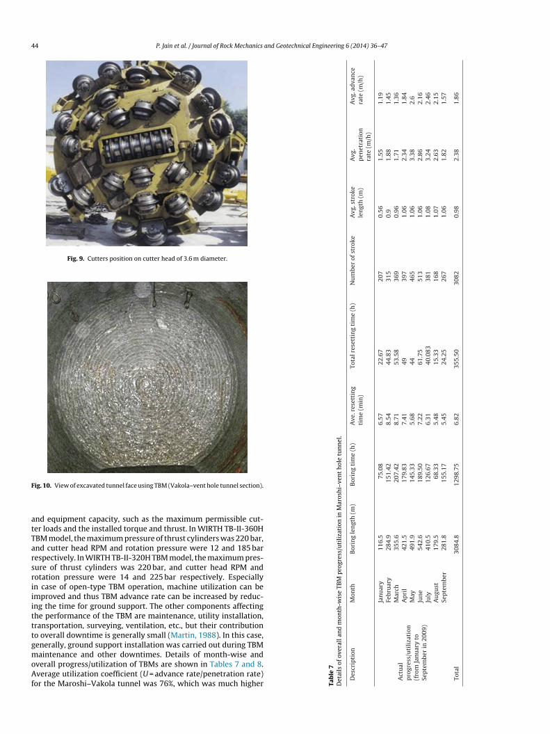
44 P. Jain et al. / Journal of Rock Mechanics and Geotechnical Engineering 6 (2014) 36–47
Fig. 9. Cutters position on cutter head of 3.6 m diameter.
F
atTarsriiitttgmoAf
7 s
of
over
all a
nd
mon
th-w
ise
TBM
pro
gres
s/u
tili
zati
on
in
Mar
osh
i–ve
nt
hol
e
tun
nel
.
crip
tion
Mon
th
Bor
ing
len
gth
(m)
Bor
ing
tim
e
(h)
Ave
. res
etti
ng
tim
e
(min
)To
tal r
eset
tin
g
tim
e
(h)
Nu
mbe
r
of
stro
ke
Avg
. str
oke
len
gth
(m)
Avg
.p
enet
rati
onra
te
(m/h
)
Avg
. ad
van
cera
te
(m/h
)
al ress
/uti
liza
tion
m
Jan
uar
y
toem
ber
in
2009
)
Jan
uar
y
116.
575
.08
6.57
22.6
720
7
0.56
1.55
1.19
Febr
uar
y
284.
9
151.
42
8.54
44.8
3
315
0.9
1.88
1.45
Mar
ch
355.
620
7.42
8.71
53.5
8
369
0.96
1.71
1.36
Ap
ril
421.
517
9.83
7.41
49
397
1.06
2.34
1.84
May
491.
9
145.
33
5.68
44
465
1.06
3.38
2.6
Jun
e
542.
618
9.50
7.22
61.7
551
3
1.06
2.86
2.16
July
410.
5
126.
67
6.31
40.0
83
381
1.08
3.24
2.46
Au
gust
179.
5
68.3
3
5.48
15.3
3
168
1.07
2.63
2.15
Sep
tem
ber
281.
8
155.
17
5.45
24.2
5
267
1.06
1.82
1.57
l
3084
.8
1298
.75
6.82
355.
50
3082
0.98
2.38
1.86
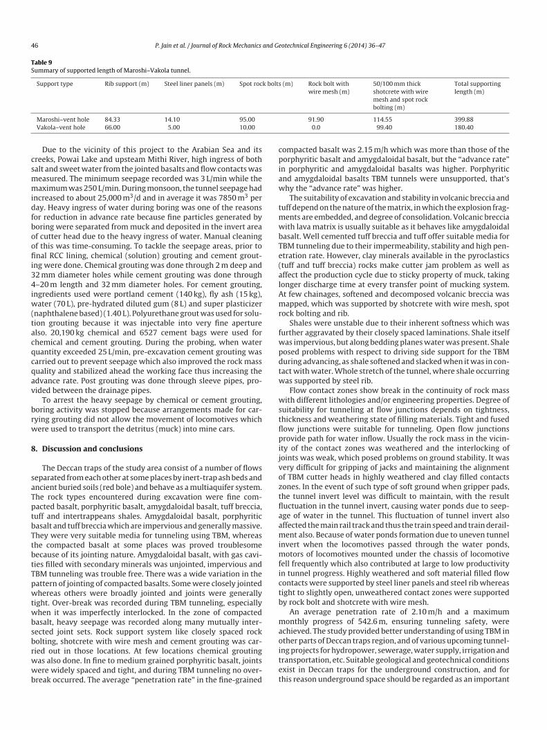
ig. 10. View of excavated tunnel face using TBM (Vakola–vent hole tunnel section).
nd equipment capacity, such as the maximum permissible cut-er loads and the installed torque and thrust. In WIRTH TB-II-360HBM model, the maximum pressure of thrust cylinders was 220 bar,nd cutter head RPM and rotation pressure were 12 and 185 barespectively. In WIRTH TB-II-320H TBM model, the maximum pres-ure of thrust cylinders was 220 bar, and cutter head RPM andotation pressure were 14 and 225 bar respectively. Especiallyn case of open-type TBM operation, machine utilization can bemproved and thus TBM advance rate can be increased by reduc-ng the time for ground support. The other components affectinghe performance of the TBM are maintenance, utility installation,ransportation, surveying, ventilation, etc., but their contributiono overall downtime is generally small (Martin, 1988). In this case,enerally, ground support installation was carried out during TBMaintenance and other downtimes. Details of month-wise and
verall progress/utilization of TBMs are shown in Tables 7 and 8.
verage utilization coefficient (U = advance rate/penetration rate)or the Maroshi–Vakola tunnel was 76%, which was much higher Tab
leD
etai
l
Des
Act
up
rog
(fro
Sep
t
Tota

P. Jain et al. / Journal of Rock Mechanics and Ge
Tab
le
8D
etai
ls
of
over
all a
nd
mon
th-w
ise
TBM
pro
gres
s/u
tili
zati
on
in
Vak
ola–
ven
t
hol
e
tun
nel
.
Des
crip
tion
Tim
e
Bor
ing
len
gth
(m)
Bor
ing
tim
e
(h)
Ave
. res
etti
ng
tim
e
(min
)To
tal r
eset
tin
g
tim
e
(h)
Nu
mbe
r
of
stro
ke
Avg
. str
oke
len
gth
(m)
Avg
.p
enet
rati
onra
te
(m/h
)
Avg
. ad
van
cera
te
(m/h
)
Act
ual
pro
gres
s/u
tili
zati
on(f
rom
Nov
embe
r20
08
to
July
2009
)
Nov
. 200
8
52.9
33.3
4
4.03
13.2
4
197
0.27
1.59
1.14
Dec
. 200
826
1.6
159.
585.
9041
.92
426
0.61
1.64
1.30
Jan
. 200
9
271.
3
193.
75
11.2
2
59.0
8
316
0.86
1.40
1.07
Feb.
2009
474.
422
8.17
10.1
077
.58
461
1.03
2.08
1.55
Mar
. 200
9
381.
0
189.
17
10.7
4
67.8
3
379
1.01
2.01
1.48
Ap
r.
2009
352.
117
4.75
10.0
062
372
0.95
2.01
1.49
May
2009
412.
819
9.00
10.0
6
70.7
5
422
0.98
2.07
1.53
Jun
e
2009
257.
7
138.
67
12.6
1
55.9
2
266
0.97
1.86
1.32
July
2009
113.
7
69.6
7
13.1
7
26.3
3
120
0.95
1.63
1.18
Tota
l
2577
.513
86.0
99.
7647
4.66
2959
0.85
1.81
1.34
bl
7
iiotfof1i(
Q
remwtTaE
w
L
cp2c
tamrbtsw
wtshir
thpttwTr1w
otechnical Engineering 6 (2014) 36–47 45
ecause of less ground support requirements, i.e. 10.25% of tunnelength only and less cutter consumption (556 m3 per cutter).
. Support system
For the support, economic reinforcement system was selectedn order to effectively cope with the stress change of the site rockncluded by excavation and to ensure the safety. The maximumverburden cover above the crown of the tunnel varied from 65 mo 80 m which was not very high. The reinforcement pattern usedor each rock mass class was based on the reinforcement standardf Barton (2000) which was modified from Q-system standardor Norwegian Method of Tunneling (NMT) (Grimstad and Barton,993). RMR values were assessed and then converted to Q accord-
ng to the correlation between RMR and Q given by Bieniawski1989):
= e(RMR−44)/9 (1)
Since TBM tunnels have a multiple of purposes, a range of safetyequirements exists as in the case of drill-and-blast tunnels. Thexcavation support ratio (ESR) concept used in the Q-system forodifying the effective tunnel dimension, when selecting support,as used for support design in TBM tunnel. The ESR was applied
o 1.5 according to the ESR values that Barton (2000) suggested forBM support/liner selection. The equivalent dimension (De) waspplied by dividing the span of the tunnel by the fore-mentionedSR and it was 2.4 m.
The rock bolt length (L) can be estimated from the excavationidth (B) and the ESR (Barton et al., 1974):
= 2 + 0.15B
ESR(2)
By applying the above formula, the length of rock bolt was cal-ulated to be 2.36 m. The value of Barton TBM Q-system chartroposed is 2.2–2.6 m. The proposed value of basic design was.0–2.5 m, accordingly rock bolt was applied according to the siteonditions.
Tunnel support measures were applied at several specific loca-ions from work platforms behind the cutter head. Tunnel supportnd rock reinforcement methods, such as rock bolts, shotcrete, wireesh, steel rib and steel liner panel were used in TBM tunnels. The
ocks met within the tunnels were generally self-supported. Rockolt is the fastest ground support method in the open-type TBMunnel. Rock bolts of 25 mm diameter, with corresponding yieldtrength of approximately 200 kN, and steel quality of 500 N/mm2
as used.The shotcrete of 50–100 mm thickness was applied considering
hat was proposed by Q-system. Shotcrete was normally applied inhe backup area; however, under difficult conditions, 100 mm thickhotcrete with wire mesh was applied immediately behind cutteread. Steel rib with 3.15 mm MS lagging plates was also installed
n the problematic areas. Steel liner panels were used in very poorock masses where rock bearing capacity was very low.
The first support was installed at a distance ranging from 4 mo 6 m from the working face, i.e. immediately behind the cutteread shield while other supports were generally installed afterassage of the main body of the TBM. From Maroshi to vent hole,otal 399.88 m out of 3086.34 m length of tunnel and from Vakolao vent hole, total 180.40 m out of 2590.40 m length of tunnelere supported and various types of supports are summarized in
able 9. Finally, the tunnels were lined by M-20 grade 300 mm thickoller compacted concrete (RCC) lining, which was completed in6 months. Perforated drainage pipes of 2 in. diameter, attached toire mesh were provided.
46 P. Jain et al. / Journal of Rock Mechanics and Geotechnical Engineering 6 (2014) 36–47
Table 9Summary of supported length of Maroshi–Vakola tunnel.
Support type Rib support (m) Steel liner panels (m) Spot rock bolts (m) Rock bolt withwire mesh (m)
50/100 mm thickshotcrete with wiremesh and spot rockbolting (m)
Total supportinglength (m)
csmmidfboofii34iw(tacqcqav
brw
8
saTptbTtbtTpwtwbsbrwwb
cpiaw
tmwbTe(alAmr
fwpdtw
wstflpijvoztflaamimfictb
mao
Maroshi–vent hole 84.33 14.10 95.00Vakola–vent hole 66.00 5.00 10.00
Due to the vicinity of this project to the Arabian Sea and itsreeks, Powai Lake and upsteam Mithi River, high ingress of bothalt and sweet water from the jointed basalts and flow contacts waseasured. The minimum seepage recorded was 3 L/min while theaximum was 250 L/min. During monsoon, the tunnel seepage had
ncreased to about 25,000 m3/d and in average it was 7850 m3 peray. Heavy ingress of water during boring was one of the reasonsor reduction in advance rate because fine particles generated byoring were separated from muck and deposited in the invert areaf cutter head due to the heavy ingress of water. Manual cleaningf this was time-consuming. To tackle the seepage areas, prior tonal RCC lining, chemical (solution) grouting and cement grout-
ng were done. Chemical grouting was done through 2 m deep and2 mm diameter holes while cement grouting was done through–20 m length and 32 mm diameter holes. For cement grouting,
ngredients used were portland cement (140 kg), fly ash (15 kg),ater (70 L), pre-hydrated diluted gum (8 L) and super plasticizer
naphthalene based) (1.40 L). Polyurethane grout was used for solu-ion grouting because it was injectable into very fine aperturelso. 20,190 kg chemical and 6527 cement bags were used forhemical and cement grouting. During the probing, when wateruantity exceeded 25 L/min, pre-excavation cement grouting wasarried out to prevent seepage which also improved the rock massuality and stabilized ahead the working face thus increasing thedvance rate. Post grouting was done through sleeve pipes, pro-ided between the drainage pipes.
To arrest the heavy seepage by chemical or cement grouting,oring activity was stopped because arrangements made for car-ying grouting did not allow the movement of locomotives whichere used to transport the detritus (muck) into mine cars.
. Discussion and conclusions
The Deccan traps of the study area consist of a number of flowseparated from each other at some places by inert-trap ash beds andncient buried soils (red bole) and behave as a multiaquifer system.he rock types encountered during excavation were fine com-acted basalt, porphyritic basalt, amygdaloidal basalt, tuff breccia,uff and intertrappeans shales. Amygdaloidal basalt, porphyriticasalt and tuff breccia which are impervious and generally massive.hey were very suitable media for tunneling using TBM, whereashe compacted basalt at some places was proved troublesomeecause of its jointing nature. Amygdaloidal basalt, with gas cavi-ies filled with secondary minerals was unjointed, impervious andBM tunneling was trouble free. There was a wide variation in theattern of jointing of compacted basalts. Some were closely jointedhereas others were broadly jointed and joints were generally
ight. Over-break was recorded during TBM tunneling, especiallyhen it was imperfectly interlocked. In the zone of compacted
asalt, heavy seepage was recorded along many mutually inter-ected joint sets. Rock support system like closely spaced rockolting, shotcrete with wire mesh and cement grouting was car-
ied out in those locations. At few locations chemical groutingas also done. In fine to medium grained porphyritic basalt, jointsere widely spaced and tight, and during TBM tunneling no over-reak occurred. The average “penetration rate” in the fine-grained
itet
91.90 114.55 399.880.0 99.40 180.40
ompacted basalt was 2.15 m/h which was more than those of theorphyritic basalt and amygdaloidal basalt, but the “advance rate”
n porphyritic and amygdaloidal basalts was higher. Porphyriticnd amygdaloidal basalts TBM tunnels were unsupported, that’shy the “advance rate” was higher.
The suitability of excavation and stability in volcanic breccia anduff depend on the nature of the matrix, in which the explosion frag-
ents are embedded, and degree of consolidation. Volcanic brecciaith lava matrix is usually suitable as it behaves like amygdaloidal
asalt. Well cemented tuff breccia and tuff offer suitable media forBM tunneling due to their impermeability, stability and high pen-tration rate. However, clay minerals available in the pyroclasticstuff and tuff breccia) rocks make cutter jam problem as well asffect the production cycle due to sticky property of muck, takingonger discharge time at every transfer point of mucking system.t few chainages, softened and decomposed volcanic breccia wasapped, which was supported by shotcrete with wire mesh, spot
ock bolting and rib.Shales were unstable due to their inherent softness which was
urther aggravated by their closely spaced laminations. Shale itselfas impervious, but along bedding planes water was present. Shaleosed problems with respect to driving side support for the TBMuring advancing, as shale softened and slacked when it was in con-act with water. Whole stretch of the tunnel, where shale occurringas supported by steel rib.
Flow contact zones show break in the continuity of rock massith different lithologies and/or engineering properties. Degree of
uitability for tunneling at flow junctions depends on tightness,hickness and weathering state of filling materials. Tight and fusedow junctions were suitable for tunneling. Open flow junctionsrovide path for water inflow. Usually the rock mass in the vicin-
ty of the contact zones was weathered and the interlocking ofoints was weak, which posed problems on ground stability. It wasery difficult for gripping of jacks and maintaining the alignmentf TBM cutter heads in highly weathered and clay filled contactsones. In the event of such type of soft ground when gripper pads,he tunnel invert level was difficult to maintain, with the resultuctuation in the tunnel invert, causing water ponds due to seep-ge of water in the tunnel. This fluctuation of tunnel invert alsoffected the main rail track and thus the train speed and train derail-ent also. Because of water ponds formation due to uneven tunnel
nvert when the locomotives passed through the water ponds,otors of locomotives mounted under the chassis of locomotive
ell frequently which also contributed at large to low productivityn tunnel progress. Highly weathered and soft material filled flowontacts were supported by steel liner panels and steel rib whereasight to slightly open, unweathered contact zones were supportedy rock bolt and shotcrete with wire mesh.
An average penetration rate of 2.10 m/h and a maximumonthly progress of 542.6 m, ensuring tunneling safety, were
chieved. The study provided better understanding of using TBM inther parts of Deccan traps region, and of various upcoming tunnel-
ng projects for hydropower, sewerage, water supply, irrigation andransportation, etc. Suitable geological and geotechnical conditionsxist in Deccan traps for the underground construction, and forhis reason underground space should be regarded as an important
and Ge
np
A
mtHSd
R
A
A
BB
B
B
B
C
F
F
G
G
G
G
G
H
H
I
J
M
M
O
R
R
S
S
SS
congress. Rotterdam: A.A. Balkema; 1998. p. 3353–9.
P. Jain et al. / Journal of Rock Mechanics
atural resource to be utilized wisely to reduce the populationressure on surface.
cknowledgements
First two authors are thankful to Director of NIRM for the per-ission to send the manuscript for publication. Authors are grateful
o the Managements of Municipal Corporation of Greater Mumbai,industan Construction Company Limited, Mumbai and Noble Geotructs, Mumbai for providing the valuable data and helping renderuring the visit of the site.
eferences
eberli U, Wanner WJ. On the influence of discontinuities at the application of tun-neling machines. In: Proceedings of the 3rd international congress IAEG; 1978.p. 7–14.
lber M. Prediction of penetration, utilization for hard rock TBMs. In: Proceedingof the ISRM international conference of Eurock’96. Rotterdam: A.A. Balkema;1996. p. 721–5.
arton N. TBM tunneling in jointed and faulted rock. Rotterdam: A.A. Balkema; 2000.arton N, Lien R, Lunde J. Engineering classification of rock masses for the design of
tunnel support. Rock Mechanics 1974;6(4):189–236.ieniawski ZT. Engineering rock mass classification. New York: John Willey & Sons;
1989.rown ET. Rock characterization testing and monitoring: ISRM suggested methods.
Oxford and New York: Pergamon Press; 1981.ruland A. Hard rock tunnel boring. PhD Thesis. Trondheim: Norwegian University
of Science and Technology; 1998.heema S. Development of a rock mass boreability index for the performance of
tunnel boring machines. PhD Thesis. Golden, USA: Colorado School of Mines;1999.
armer IW, Glossop NH. Mechanics of disc cutter penetration. Tunnels and Tun-nelling 1980;12(6):22–5.
arrokh E, Rostami J, Laughton C. Analysis of unit supporting time and sup-port installation time for open TBMs. Rock Mechanics and Rock Engineering2011;44(4):431–45.
oel RK. Evaluation of TBM performance in a Himalayan tunnel. In: Proceedings ofworld tunnel congress 2008—underground facilities for better environment andsafety; 2008. p. 1522–32.
ong QM, Zhao J. Influence of rock brittleness on TBM penetration rate in Singaporegranite. Tunnelling and Underground Space Technology 2007;22(3):317–24.
ong QM, Zhao J. Development of a rock mass characteristics model for TBM pen-etration rate prediction. International Journal of Rock Mechanics and MiningSciences 2009;46(1):8–18.
T
otechnical Engineering 6 (2014) 36–47 47
raham PC. Rock exploration for machine manufacturers. In: Bieniawski ZT, edi-tor. Exploration for rock engineering. Johannesburg: A.A. Balkema; 1976. p.173–80.
rimstad E, Barton N. Updating of the Q-system for NMT. In: Proceedings of theinternational symposium on sprayed concrete—modern use of wet mix sprayedconcrete for underground support. Oslo: Norwegian Concrete Association; 1993.p. 46–66.
amidi JK, Shahriar K, Rezai B, Rostami J. Performance prediction of hard rockTBM using Rock Mass Rating (RMR) system. Tunnelling and Underground SpaceTechnology 2010;25(4):333–45.
owarth DF. The effect of jointed and fissured rock on the performance of tunnelboring machines. In: Proceedings of ISRM international symposium on weakrock; 1981. p. 1069–74.
nnaurato N, Mancini R, Rondena E, Zaninetti A. Forcasting and effective TBM per-formances in a rapid excavation of a tunnel in Italy. In: Wittke W, editor.Proceedings of the 7th international congress on rock mechanics; 1991. p.1009–14.
ain P, Naithani AK, Singh TN. Application of tunnel boring machine for the construc-tion of Maroshi–Ruparel College Tunnel–Mumbai, India. Journal of EngineeringGeology 2011;37(1–4):151–9.
artin D. TBM tunnelling in poor and very poor rock conditions. Tunnels and Tun-nelling 1988;20(3):22–7.
cFeat-Smith I, Broomfield J. Mechanised tunneling for Asia: realising the ben-efits, avoiding the pitfalls, workshop manual. IMS Tunnel Consultancy Ltd;1997.
’Rourke JE, Spring JE, Coudray SV. Geotechnical parameters and tunnel boringmachine performance at Goodwill Tunnel, California. In: Nelson PP, LaubachSE, editors. Proceedings of the 1st North American rock mechanics symposium.Rotterdam: A.A. Balkema; 1994.
obbins RJ. Tunnel mechanics in hard rock. In: Civil engineering for undergroundrail transport. London: Butterworth; 1990. p. 365–8.
ostami J, Ozdemir L. A new model for performance prediction of hard rockTBMs. In: Rapid excavation and tunneling conference proceedings; 1993. p.793–809.
apigni M, Berti M, Bethaz E, Busillo A, Cardone G. TBM performance estimationusing rock mass classifications. International Journal of Rock Mechanics andMining Sciences 2002;39(6):771–88.
ethna SF. Geology of Mumbai and surrounding areas and its position in the Dec-can Volcanic Stratigraphy, India. Journal of the Geological Society of India1999;53:359–65.
ubbarao KV. Deccan flood basalts. Bangalore: Geological Society of India; 1988.undaram NM, Komoo I, Rafek AG. The influence of rock mass properties in the
assessment of TBM performance. In: Proceedings of the 8th international IAEG
huro K, Plinninger RJ. Hard rock tunnel boring, cutting, drilling and blasting: rockparameters for excavatability. In: ISRM 2003 – technology roadmap for rockmechanics. Johannesburg: South African Institute of Mining and Metallurgy;2003. p. 1–7.