jp pump repair manual
TRANSCRIPT

MAINTENANCE MANUAL
MÁQUINAS AGRÍCOLAS JACTO S.A.Rua Dr. Luiz Miranda, 1650
17580-000 - Pompéia - SP - BrazilTel.: +55 14 452-1811 - Fax: +55 14 452-1306
E-mail: [email protected]
08/99 - 750935 - MI-0097
PUMPSJP-4022857
JP-750414
JP-1000293
JP-1500431
JP-3000640

STATEMENT OF LIMITED WARRANTY
WARRANTY EXCLUSIONS:- Parts considered as normal maintenance such as: filtering elements, belts, hoses,nozzles, pistons, pressure gauges, as well as usual maintenance, adjustments,retightening, lubrication and painting.- Parts which show wear or tear due to use, UNLESS THEY SHOW DEFECTS INWORKMANSHIP, ASSEMBLY OR MATERIAL.- Hydraulic, lubricating oils and grease.- Injuries of personal or material nature to the user, owner, or third parties.- Additional charges resulting from paralyzation and repair of the equipment.- Freight charges, pick up and delivery charges.- Damages of any nature resulting from action of gases or liquids used in the equipment.
GENERAL INFORMATION:- Defective parts replaced under warranty period shall be property of JACTO.- Eventual delays in performing services do not confer to the owner the right toindemnity or to extension of the warranty period.- JACTO reserves the right to change its products or to interrupt manufacturing theequipment.- THIS LIMITED WARRANTY shall be understood by its expressed terms, and no one inanyway subject to JACTO shall be authorized to modify or amplify the conditions prescribedherein.- In case of need for warranty request, call for the authorized dealer supplying allinformation required for a prompt compliance. Do not forget the identification of theequipment, total hours of work, and the noticed defect.
FOR THIS WARRANTY TO BECOME EFFECTIVE THE PRODUCT REGISTRATIONCARD FOUND IN THE INSTRUCTION MANUAL MUST BE FILLED IN AND RETURNEDTO YOUR JACTO DEALER. THIS CARD MUST BE SIGNED BY THE ORIGINAL RETAILBUYER, INDICATING THAT HE HAS READ AND UNDERSTOOD ALL SAFETY ANDOPERATIONAL INTRUCTIONS IN THE MANUAL. FURTHER THE RETAILING DEALERHAS EXPLAINED TO THE ORIGINAL RETAIL BUYER ALL SAFETY INSTRUCTIONS. INNO CASE WILL WARRANTY BE SUPPLIED UNTIL THIS CARD, PROPERLY COMPLETEDAND SIGNED, IS ON FILE WITH JACTO RETAILING DEALER. A COPY OF THE PRODUCTREGISTRATION CARD SHOULD BE KEPT BY THE ORIGINAL OWNER, AS WELL AS
THE COMMERCIAL INVOICE.
39

PresentationIntroduction ............................................................................................................. 04Identification plate .................................................................................................. 04Specifications ......................................................................................................... 05Maintenance tools ........................................................................................... .05
Maintenance of JP-402 pump Disassembling the pump
I - Disassembling the hydraulic part ................................................................... 07II - Disassembling the mechanical part ................................................................. 08Assembling the pumpIII - Crankshaft ...................................................................................................... 10IV - Crankshaft and pump body ............................................................................. 12V - Piston ............................................................................................................. 13VI - Valves ............................................................................................................. 14VII - Valve Analysis ................................................................................................ 15VIII - Head ........................................................................................................16IX - Lubrication ...................................................................................................... 16X - Final tests ....................................................................................................... 17
Maintenance of JP-75 / 100 / 150 / 300 pumpsTrouble-shooting
1 - Excessive liquid leakage through the drain hole .............................................. 192 - Liquid leakage between the cylinder and head................................................. 193 - Lubricating oil leakage through the drain hole .................................................. 204 - Defficient suction and pumping ........................................................................ 205 - Inner noises .................................................................................................... 216 - Preventive maintenance................................................................................... 21
Disassembling the pump1 - Disassembling the hydraulic part .................................................................... 222 - Disassembling the mechanical part ................................................................. 24
Checking the parts condition1 - Piston cup ...................................................................................................... 262 - Tappet/Connecting rod .................................................................................... 263 - Rod guide housing .......................................................................................... 274 - Crankshaft ...................................................................................................... 275 - Valves ............................................................................................................. 276 - Valve spring test ............................................................................................. 287 - Valve seal test ................................................................................................ 28
Assembling the pump1 - Bearing and crankshaft ................................................................................... 292 - Connecting rod and rodded guide .................................................................... 303 - Crankshaft ...................................................................................................... 314 - Flanges ........................................................................................................... 325 - Cylinder guide and ceramic cylinder ................................................................ 336 - Valves ............................................................................................................. 347 - Head and valves cover ..................................................................................... 348 - Plugs ............................................................................................................. 359 - Assembling and filling ..................................................................................... 3610- Lubrication ...................................................................................................... 37
Statement of limited warranty ................................................................................... 38
TABLE OF CONTENTS
0338
STATEMENT OF LIMITED WARRANTY
MÁQUINAS AGRÍCOLAS JACTO S.A. warrants the equipment described
herein and agrees to repair or replace parts and components which, under normal
operation and wear, following the technical recommendations, show DEFECTS
IN MATERIAL OR WORKMANSHIP.
- WARRANTY PERIOD
- One (1) year from the purchase date by the original retail purchaser.
- WARRANTY APPLICATION:
Jacto or its authorized representative shall honor this warranty, if any part or
component shows confirmed defect in workmanship.
- IT SHALL BE UNDERSTOOD THAT THE REPLACEMENT OF ASSEMBLIES
SHALL BE ONLY PERFORMED IN CASE THAT THE DEFECT CANNOT BE
REPAIRED BY REPLACING PARTS AND/OR COMPONENTS.
THIS WARRANTY IS NULL AND VOID IF:
- Equipament is not used in accordance with the INSTRUCTIONS MANUAL,
overwork or accidents,
- Improper preventive maintenance or performed by unauthorized people.
- Modification of the equipment in any way from the original design.
- Change, damage, or loss of the product indentification plate.
- Utilization of parts and components not supplied by JACTO.
PRODUCT REGISTRATION CARD MUST BE COMPLETED BY THE
ORIGINAL RETAIL PURCHASER, AND RETURNED TO JACTO DEALER
WITHIN 30 DAYS OF THE PURCHASED DATE.

INTRODUCTION
04
INTRODUCTION
If used under good conditions, that is, with clean and sand-free water, properly
diluted agrochemicals and daily cleaning, Jacto pumps are able to work for more
than 500 hours with no need for repairs.
On the other hand, when using water containing sand and ill-diluted wettable
powders, the pistons suffer early wear due to use and thus cause liquid leakages
through the drain hole . Operating the pump of your sprayer for prolonged time with
leakages will contaminate the grease (JP-402)and the lubricating oil (other pumps)
and incorrect lubrication will cause damage to the connecting rods and bearings,
thus raising the maintenance cost.
IDENTIFICATION PLATE
In requesting replacement parts or maintenance, always specify the model
and serial number of your pump for prompt and efficient service. These data are
shown on the identification plate affixed to your pump.
SPRAYER NUMBER
MÁQUINAS AGRÍCOLAS JACTO S.A - CGC 55.064.562/0001-90POMPÉIA - S.P. - MADE IN BRAZIL
MODEL:
MAX. PRESSURE kgf/cm²
ROTATION: rpm POWER.: HP
FLOW RATE: liters/min
Jacto is trademark registered by Máquinas Agrícolas Jacto S.A.
ASSEMBLING THE PUMP
NOTE: The pump must be placed on a level surface.
- Fit the level plug and oil plug (breather).
-Test the pump with clean water under around 14 kgf/cm² (200 psi) during
10 minutes.
ATTENTION: Check for eventual leakages, vibrations, strange or excessive
noize. In case of doubt, please do not hesitate to contact your Jacto dealer.
10-LUBRICATION
PRODUCT PUMP QUANTITYRECOMMENDED
PRODUCTSFREQUENCY
Lubricationoil
1st change:30 hours
Further: every
100 h
JP-75
JP-100
JP-150
1.5 liters
2.0 liters
2.5 liters
API-SB orSuperiorSAE-30
JP-300 4.0 liters
WARNING
The maintenance instructions herein must only be applied to the pump
after the expiration of the one-year warranty term which shall be in force
as of the purchase date. Within said period the user shall be authorized
only to perform the replacement of parts subject to usual wear such as
piston cups, seals and change of lubricating oil. This except, contact your
Jacto dealer.
37

05
SPECIFICATIONS
Max. rotation on crankshaft
Maximum working pressure
Flow rate (liters/min at 540 rpm)
Power required at 400 psi
Weight
540 rpm
500 psi
75
5.3 HP
37 kg
540 rpm
500 psi
100
7.0 HP
47 kg
540 rpm
500psi
150
10.7 HP
60 kg
FEATURESJP-75 JP-100 JP-150
PUMP MODEL
SPECIFICATIONS
JP-402 JP-300
540 rpm
500 psi
300
24.0 HP
125 kg
540 rpm
300 psi
40
2.2 HP
19.5 kg
X
X
X
X
X
X
X
X
X
X
X
X
X
X
X
X
X
X
X
X
X
X
DESCRIPTIONJP-75 JP-100 JP-150
PUMP MODEL
MAINTENANCE TOOLS
L 1/2" spanner
L 9/16" spanner
L 3/4" spanner
7/16" multiended wrench
1/2" multiended wrench
3/4" multiended wrench
3/4" open-ended spanner
15/16" multiended wrench
15/16" open-ended spanner
Pliers for inner plastic ring
Plastic mallet
Torque wrench
1/2" socke wrench
9/16" socket wrench
3/4" socket wrench
15/16" socket wrench
X
X
X
X
X
X
X
X
X
X
JP-402 JP-300
X
X
X
X
X
X
X
X
X
X
X
X
X
X
X
X
X
X
36
ASSEMBLING THE PUMP
0419
9- Mounting and Filling
-Install the cork seal and mount the cover
- Install the drain plug with the ring.
- Fill the pump with lubricating oil up to the level plug.
Breather
Oil level
Level plug
Cover
Cork seal
RingDrain plug

06
JP-402 PUMPMAINTENANCE
2857
ASSEMBLING THE PUMP
8- Plugs
-Mount the plugs with chemical bond or teflon tube sealer.
NOTE: The position of plugs and inlet and outlet nipples can vary according to the
equipment. Please note their positions when disassembling the pump.
0415
InletPlug
PlugOutlet
35

07
DISASSEMBLING THE PUMP
1 - Identify and mark the liquid inlet andoutlet of the pump.
2807 2808
2 - Remove the heads and observe howthe inlet and outlet valves are mounted,in order to not mount it invert.
2809
I - Disassembling the hydraulic part (heads)
outlet
inlet
2810
Outletvalve
Inlet valve
34
ASSEMBLING THE PUMP
6- VALVES
- Fit the spring and the disc into the cage.
- Position the seat and the guide ring.
- Install the valve seal.
417
Seat
Spring
Guide ring
Valve seal
Disc
Cage
- Apply two drops of low
torque chemical bond to the
stud bolts and assemble.
-Mount the clip plate, install
the lock washers, apply two
drops of medium torque
chemical bond to the stud
bolt, fit all nuts and next
tighten them with 4.5kgf/m
torque for the JP-150 and
JP-300 pump.
NOTE:
Always observe the arrow
when mounting the head and
the valves.
0416
Grease
Packingring
Stud bolt
Clip plate
Head
Valve
Ceramicsleeve
Torque(4.5 kgf/mfor JP-75
and JP-100and 5.5 kgf/
m for JP-150 and
300)
Clearanceallowed
Torque (4.5 kgf/m forJP-75 and JP-100, and
5.5 kgf/m for JP-150 and 300)
Valve cover
7- Head and valves cover
ATTENTION:
Make sure the parts are clean, free from
impurities and mainly from abrasive
chemicals

08
DISASSEMBLING THE PUMP
2813
3 - Remove the bolt that is fixing the pistonand take out the whole assembly.
- bolt,
- piston,
- piston cup,
- sleeve,
- connecting rod guide, etc.
4 - Repeat this operation on the other head.
II - DISASSEMBLING THE MECHANICAL PART
1 -Remove the cover and the connectingrod.
2817 2818
2 - Remove the dust guard and the sealwith a spatula.
Cover
Connectingrod
Pump body
Protector
ASSEMBLING THE PUMP
5-Sleeve guide and ceramic sleeve-Install the seal, snap ring and scraper ring in the sleeve guide.NOTE: Make sure the seal is positioned correctly.
- Position the paper seal and mount the sleeve guide to the pump body.-Mount the piston cup and the piston to the ceramic liner.- Position the paper seal on the liner guide and the piston cup base on the rod.- Mount the sleeve with the piston cup, position the ring, install the brass washer,apply two drops of medium torque chemical bond to the rod thread and next fit thenut.- Tighten the nut all the way with 4.5 kgf/m torque for the JP-75 & JP-100 pumpsand 5.5 kgf/m torque for the JP-150 & JP-300 pumps.
0420 Nut
Brass waher
Pistoncup
Paper seal
Scraper ring
Seal
Snap ring
Piston cup base
Ceramic sleeve
Paperseal
Sleeve guide
Ring
Piston
Torque
33

09
DISASSEMBLING THE PUMP
3 - Remove the snap ring that is placedin the pump body.
2819 2820
4 - Tap the crankshaft with a brass stickto remove it from the pump body.
Attention: Never tap the small bearingshaft to avoid damaged.
Snap ringBrass or
wood stickCrankshaft
Small bearingshaft
5 - Remove the cranksaft bearings with an extractor, or use a press properlysupported.
2821
32
ASSEMBLING THE PUMP
4- Flanges
- Lubricate with oil (API-SB ou superior SAE-30) the flanges housing and install
the seal.
- Lubricate the seal with grease. Next mount the paper seal.
- Mount the flanges to the pump body and fit all screws.
- Tighten the screws with 1.6 kgf/m torque.
0422Seal Bearing flange
Make sure the seal iscorrectly positioned.
Bearing Flange
Packing
Torque(1.6 kgf/m)

10
ASSEMBLING THE PUMP
2844
1 - Check if the lubrication channels areobstructed.
2823 2824
2 - Mount the bearing (with the greasedeflector toward the outside). Tap untilit rests.
*The bearing is armor-plated on oneside, which must be toward the outsideso that the other receives the lubrication.
III - Crankshaft
NOTE: THE TUBE USED TO MOUNT THE BEARING SHOULD TOUCH ONLYTHE BEARING INNER TRACK.
Lubricationchannel
Tube
Bearing*
CrankshaftWood basis
ASSEMBLING THE PUMP
3-Crankshaft
- Lubricate with oil (API-SB or superior SAE-30) the bearings housing.
- Mount the crankshaft with the bearings to the pump body.
-Lubricate with oil (API-SB or superior SAE-30) the crankshaft journals.
- Mount the other part of the connecting rod and fit the screws (apply low torque
chemical bond) by following the numerical sequence engraved on the connecting
rod.
- Tighten the screws all the way: 1.9 kgf/m torque for the JP-75 & JP-100 pumps
and 2.8 kgf/m torque for the JP-150 pump.
NOTE: Make sure the crankshaft can be turned with the hands after being tightened.
The position of the crankshaft may vary on eachequipment. Please note the groove positionwhen disassembling the pump.
The crankshaft assembly way andnumerical sequence of the connectingrod: a) 1.1, 2.2, 3.3 (3 -piston model)b) 1.1, 2.2, 3.3, 4.4 (4-piston model).
0421
Pump body
Rod
Groove
Bearing
Connectingrod
31

11
ASSEMBLING THE PUMP
3 - Install the spacer ring and the otherbearing with the grease deflector facingthe outside.
2825 2826
NOTE: To support the crankshaft use apiece of wood with a hole,in which to fitthe small bearing shaft.
4 - Needle bearing.
2827 2828
- Mount the bearing and lock it.
Smallbearing
shaft
Spacer ring
Base
NOTE: The armor -plated side mustface the outside. Small bearing shaft
housing
Base
30
ASSEMBLING THE PUMP
2- Connecting rod and rodded guide
NOTE: Make sure they are clean.
- Fit the connecting rod into the rodded guide.
- Lubricate with oil (API-SB or superior SAE-30) the connecting rod pin and
mount the assembly.
- Lubricate with oil (API-SB or superior SAE-30) the rodded guide and the guide
housing (on the pump body). Next mount this assemly to the pump body as shown
in the figure below.
0418
Pin
Connectingrod
Rod guide
Oil
Rod

12
ASSEMBLING THE PUMP
1 - Align the crankshaft assembly to thepump body and tap the external cap (usea tube) until housing completely theassembly.
2845
2846
2 - Lock the entire assembly byinstaling the snap ring.
3 - Place the seal and the dust guard.
2847
2848
IV - Mounting the crankshaft assembly to the pump body
2848
5 - Lubricate the pump withgrease.
NOTE: Place the seal with the edge upward,so the seal can eliminate the grease excessand prevent dirts from entering.
4 -Install the matching cover and the external cover.-Fit the screws and tighten them sequencedcrosswise with 0.5 kgf/m torque.
External cover
Matching cover
ASSEMBLING THE PUMP
Some specifc tools are required for assembling the pump. In case you do not
have them, try to use those available, provided that you do not damage the parts.
Follow strictly the sequence shown below.
1- Bearing and crankshaft assembly
NOTE: Make sure they are clean.
- Place the crankshaft on the aluminum plate.
- Install the bearing guide
- Position the bearing with the numbers upward.
- Press the bearing until it is set to the indicated position.
- Disassemble the extension and guide.
NOTE: To follow the same sequence for mounting the other bearing..
Extension
Bearing seat
Crankshaft
Bearing guide
Bearing
Aluminum plate
0423
Gasket tightener
29

13
ASSEMBLING THE PUMP
1 - Install the seal and the seat washer.
2850 2851
2 - Fit the spacer bushing and the o-ringover the spacer bushing.
3 - Mount the ceramic sleeve and the
o-ring around the sleeve.
2836
4 -Install the tappet on the connectingrod with the piston cup guide.
2852
V - Mounting the pistons assembly
28
CHECKING THE PARTS CONDITION
7-Valve seal
- Place a thin sandpaper on a straightener and smooth the seating sides of thedisc and valve seat with 8-shaped movements.
- Mount the valve and pour water as
shown in the figure.
- If it leaks, replace the valve.
ATTENTION
Replace the seals whenever disassembling the valve for repair.
0426
0427
200 g 100 g
Spring
Cage
Seal
Seat
6- Valve spring
-Fit the spring, packing disc and
seat in the cage.
-Place weights of 100 g (for JP-75 &
JP-100 pumps) and 200 g (for JP-150
& JP-300 pumps) on the seat and
check if the seat rests on the cage. If
not, replace the spring and test again.
Valve with improper seal caused by wear, impurities or stuck disc results in
deficient suction and pumping.
Water

2853
5 - Install the piston cup with thepiston.
6 - Fit the fixing bolt with the o-ringand the flat washer.
2854
2855
7 - Tighten it with 3.5 kgf/m torque.
14
ASSEMBLING THE PUMP
8 - Do the same with the other piston assembly.
VI- VALVES
- Fit the spring and the disc into the cage.
- Position the seat and the guide ring.
- Install the valve seal.
0417
Seat
Spring
Guide ring
Valve seal
Disc
Cage
ATTENTION:
Make sure the parts are clean, free from
impurities and mainly from abrasive
chemicals
CHECKING THE PARTS CONDITION
ATTENTION: Overcharge on the valve spring will result in deficient suctionand pumping.
5-ValvesCheck:1-Cage2- Spring3- Packing disc4- Seat5- Seal6- Valve guide
3- Rod guide housing-Check if it is not slack or worn.
4- Crankshaft- Check if the crankshaft journal is not scratched.
0398
0407
0411
Rod guidehousing
6 5 4 3 2 1
Crankshaftjournal
27

15
ASSEMBLING THE PUMP
2- Valve seal
- Place a thin sandpaper on a straightener and smooth the seating sides of thedisc and valve seat with 8-shaped movements.
- Mount the valve and pour water
as shown in the figure.
- If it leaks, replace the valve.
ATTENTION
Replace the seals whenever disassembling the valve for repair.
3158
0427
100 g
Spring
Cage
Seal
Seat
1- Valve spring
-Fit the spring, packing disc and
seat in the cage.
-Place weights of 100 g (for JP-75 &
JP-100 pumps) and 200 g (for JP-150
& JP-300 pumps) on the seat and
check if the seat rests on the cage. If
not, replace the spring and test again.
Valve with improper seal caused by wear, impurities or stuck disc results in
deficient suction and pumping.
Water
VII- VALVE ANALYSIS
26
CHECKING THE PARTS CONDITION
1-Piston cup
Condition Causes
Normal wear due to time of use.
a) Improper maintenance - the inside of the pumpis not rinsed after the application of wettablepowdered agrochemicals which are built up onthe cylinder and head walls.b) Use of water containing sand - improperfiltering during the filling operation.c) Chemical mixture leakage when using wettablepowdered agrochemicals.
ATTENTION: Whenever disassembling the sleeve and piston cup assembly for
repair, replace the following parts (see figure 0430): sleeve seal (3), packing ring
(06) and packing ring(10).
Thinner wall
Wear and scratch
2- Tappet - Connecting rod
- Check if the guides and rods are not worn or scratched.
- Check if the connecting rod pin is not worn.
- Check if the connecting rod eye is not worn.
- Check if the connecting rod bearing is not worn or scratched.
Worn or scratched pistoncups cause liquid leakagethrough the drain hole.
0400
0434 0435
Connectingrod bearing
Rod Guide Connectingrod
Pin
Normal Worn

16
2843
- Mount the bearing and lock it.
- Mount the heads according to the identification (inlet and outlet) made on thebegining of the disassembling.
TORQUES:
1st fase1.4 to 2 kgf/m (10 to 15 lb/foot).
2nd fase2.8 to 3.5 kgf/m (20 to 35 lb/foot).
3rd fase:3.5 kgf/m (25 lb/foot).
IX - Lubrication-Lubricate the pump daily, using Lithiun base NGLI-2 grease.
Grease nipple
2857
ASSEMBLING THE PUMP
VIII - Assembling the head
DISASSEMBLING THE MECHANICAL PART
2.5 - Remove the tappets with the connecting rod and the connecting rod pin.
0404
0405
Crankshaft
2.4- Pull out all the tappets to the front so as to free the crankshaft.
NOTE: Remove the crankshaft carefully in order to avoid impact on the
connecting rod journal.
Connecting rodpin
TappetConnecting
rod
25

X - FINAL TESTS
After finishing the pump assembly, do the following tests to check if thepump was correctly repaired.
1st test: Operate the pump for 10 minutes with no pressure in the circuit.
2nd test:. LIQUID LEAKAGE THROUGH THE DRAIN HOLE.
Check if the leakage was eliminated by operating the pump with pressurein the circuit.
3rd test: WEAR OF MOVING PARTS
Check if the clearance on the bearings and the strong metallic noises wereeliminated with the pump running at the working pressure.
4th test: SUCTION AND PUMPING DEFICIENCY
Determine the pump actual capacity.( REFER TO THE INFORMATIONSHEET )
ASSEMBLING THE PUMP
1724
DISASSEMBLING THE MECHANICAL PART
2-Disassembling the mechanical part
2.1- Remove the crankcase cover.
2.2- Remove the bolts that fix the
connecting rods.
0432
0433
Crankcasecover
Connecting rod
Crankshaft
Drainplug
2.3-Remove the bolts and
the flanges
0403
Flange
18
JP-75 / 100 / 150 / 300PUMPS MAINTENANCE
JP-750414
JP-1000293
JP-1500431
JP-3000640
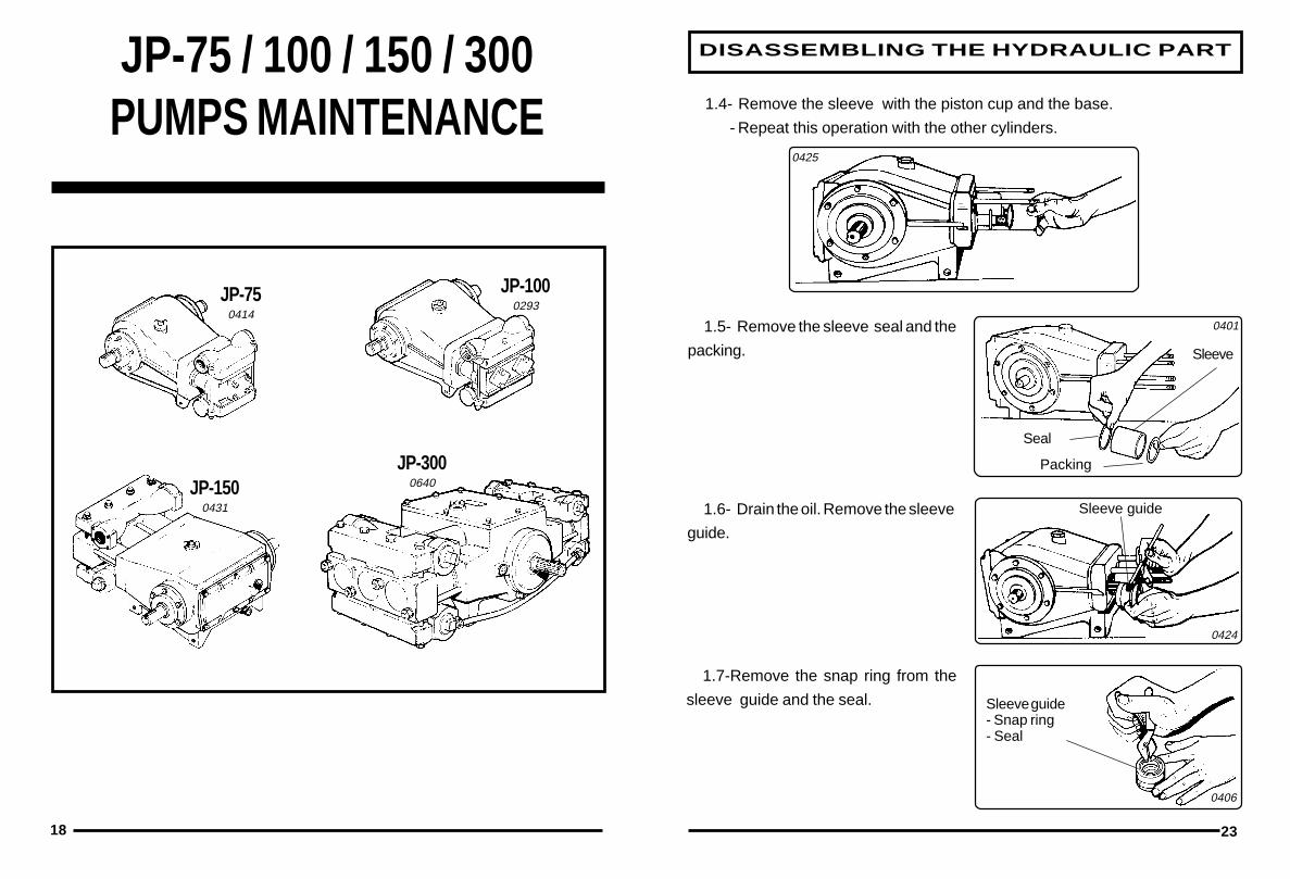
DISASSEMBLING THE HYDRAULIC PART
1.5- Remove the sleeve seal and the
packing.
1.6- Drain the oil. Remove the sleeve
guide.
1.7-Remove the snap ring from the
sleeve guide and the seal.
1.4- Remove the sleeve with the piston cup and the base.
- Repeat this operation with the other cylinders.
0425
0401
0424
0406
Packing
Seal
Sleeve
Sleeve guide
Sleeve guide- Snap ring- Seal
23

TROUBLE-SHOOTING
1- Excessive liquid leakage through the drain hole.
There will be leakage if:
- the piston cup is damaged (fig. 0430 - part 8).
- the nut fixing the piston cup is not tightened. (fig. 0430 - part 12).
- the packing ring is damaged (fig. 0430 - part 10).
2- Liquid leakage between the sleeve and head.
- Retighten the head nuts (fig. 0429).
- If the leakage continues, replace the packing ring (fig. 0430 - part 6).
0402
04280429
Drain
Packing ring
Drain
14
3
2
1922
DISASSEMBLING THE HYDRAULIC PART
1.1- Remove the nuts fixing the head,clip plates and head.
1.2- Remove the nut fixing the piston
cup.
1.3- Remove the nut (12), brass washer (11), packing ring (10) and piston ( 9).
1-Disassembling the hydraulic part- Remove the stud bolts fixing the
valves cover.
- Remove the valves cover.
ATTENTION: Observe the parts when disassembling the pump in order toidentify those damaged.
0410
0408
0409
0430
Stud bolt
Valvescover
Clip plate
Head
1 2 3 4 3 5 6 7 8 9 10 11 12

TROUBLE-SHOOTING
20
5- Inner noises
These noises result from wear on the connecting rod bearing.
ATTENTION: Check for the exact location of the noises. There may also be noises
if the filter is obstructed or a valve is not operating properly, thus leading you to a
wrong diagnosis.
6- Preventive maintenance
Pumps have parts which usually operate under rigorous conditions and thus are
subject to normal wear after a reasonable time of use. On our pumps the piston cup,
which is in continuous contact with abrasive chemical mixtures, is subject to wear
and therefore can cause liquid leakage through the drain hole. To avoid that such
a simple problem damage other parts of the pump, a preventive maintenance at the
end of the spraying season or every 300 hours is advisable , with the examination
of the pistons set and replament of the damaged parts.
0400
Connecting rodbearing
21
- Disconnect the return hose from the control valve and connect the filler unit hose.- Run the sprayer with 540 rpm at PTO.
- Collect water for one minute.- Measure the volume collected.
NOTE: The volume collected shouldapproximate this shown below for eachpump model:JP-402 = 40 litersminJP-75 = 75 liters/minJP-100 = 100 liters/minJP-150 = 150 liters/minJP-300 = 300 liters/min
TROUBLE-SHOOTING
3- Lubricating oil leakage through the drain holeThis can happen due to obstruction in the breather, deficient rod seal
(part 02) and sleeve guide seal (part 3) or improper tightening of the nuts fixing thehead.
01 - Snap ring02 - Seal03 - Packing04 - Sleeve guide05 - Sleeve06 - Packing ring
07 - Piston cup seat08 - Piston cup09 - Piston10 - Packing ring11 - Flat washer12 - Nut
0430
1 2 3 4 3 5 6 7 8 9 10 11 12
4- Deficient suction and pumpingIt can be caused by:-Damaged valve;- deficient packing on the valves due to impurities or stuck disc;- incorrect mounting of valves.
To confirm if this deficiency is really caused by the valves, measure the pumpactual flow rate.
0412
Filler unithose
Return hose