judy’s jams and jellies
TRANSCRIPT

1
Judy’sJams and Jellies
Instructions for Assemblyof the HO ScaleJudy’s Jams and Jellies
Kit Contents: 204 ea. white 1/16" laser cut acrylic part80ea. adhesive-backed brick parts (7 sizes)4 ea PVC pipe (5/8"x2", 1 1/16"x2", 1 1/16"x3.25", 1 5/16"x1")2 ea. 7.5" plastic coated wire1 ea. 2" x 1/8" round styrene rod4 ea. acetate4 ea. printed window shadesprinted signs1 sheet double-sided adhesive
Thank you for purchasing this kit. Please read these instructions completely before beginning andtake your time. Allow parts to dry after painting or gluing and do not try to build this in onenight.
Drawings of all the parts have been included for ease of part identification.
Practice gluing the acrylic together if you have never done it before. Scrap acrylic is included.
If by chance a part is missing or broken, please contact us indicating the kit name and partnumber and we will send you a replacement.
You will need the following items to assemble your model: Sharp hobby knife, file, paint (see“Painting Your Model”), paint brushes, glue (see “Gluing Acrylic”), and modeling putty.
About the Kit
A jelly factory? What were we thinking? Well...think of the possibilities. Fresh fruit from thesouth, jars from the glass factory, labels and boxes from the printer, sugar from the refinery. Andthen it all goes back out as freight to the grocery wholesaler. That could be quite a bit of railtraffic.

2
Originally the Furman Gear Company, the factory has been re-adapted as a food processing plant. Later in life it may end up as some other manufacturing company or maybe even condos. It hasrail service on one side and truck service on the end. There is a street entrance for the corporateoffice as well as some garage doors for the delivery trucks. A very versatile and adaptablebuilding that can be converted into just about any type of industry. Your imagination is the limit.
The kit is built up in modules labeled as units. Parts are labeled in the instructions insideparentheses. The first number is the unit number and the second is the part number in that unit.For instance (2-6) would be part six in unit two.
Gluing Acrylic
Always glue acrylic in a well-ventilated area, and read the glue manufacturer’s label forinstructions.
We recommend using Plastruct brand “Plastic Weld Solvent Cement” (PPC-2 or PPC-16) or“Bondine Solvent Cement”(Bond-2 or BOND-16). Plastruct sells a Solvent Syringe (HT-8 orHT-10) and various other solvent dispensers. Most hobby shops carry these products or they maybe ordered directly from Plastruct.
Acrylic must be glued together using a solvent that will melt the two edges and literally fusethem together. To do this, place the two pieces to be joined together and run a bead of solventdown the edge. Capillary action will suck the solvent into the joint and after several seconds thepieces will be fused. After only a few minutes the pieces will be strong enough to work with. Thebond will be completely dry within twenty-four hours using the above-mentioned products.
Solvent can be dispensed two ways. Typically the solvent comes in a small bottle with a brush inthe lid. The brush allows you to dispense a drop or two of solvent at a time. You may want touse a polyethylene bottle or syringe with a blunt needle dispenser. This allows larger amounts ofsolvent to be dispensed quickly and cleanly. Be sure the bottle you are using is approved for thesolvent you are using or you may melt through it. These may be purchased from CMR.
For this model, glue the windows into each building unit using super glue (CA). We alsorecommend using white glue for attaching some parts (where noted) because of its slower dryingtime and ease of cleaning up any excess.
Preparing Your Model for Painting
Lightly sand all parts to remove the raised edge created during the laser cutting process. In orderto hide any seams use “hobbyist putty” such as Green Squadron modeling putty. Do this in a wellventilated area. Apply the putty over the seams; allow to dry overnight. Once the putty has drieduse a sanding block to smooth. You may need to apply a second coat of putty and sand again.
Sometimes it is necessary to sand or file the tabs slightly in order to get them to seat themselvesinto the slots. This is due to slight variations in acrylic thickness. If the tabs are not fitting intothe slots you may need to file them back at an angle to fit properly.

3
Painting Your Model
For our building paint scheme, we used Krylon spray paints which are available in mosthardware stores or directly from Sherwin Williams Paints. We also used “Polly Scale Acrylics”for details and weathering. These are available in most hobby shops.
Always test compatibility of your paint with the acrylic by painting and testing a small area first.Alcohol can cause acrylic to crack and “shatter”. Do not use alcohol to clean the parts or alcohol-based paints. If you apply washes to your building we recommend using a water-based wash.
If you plan to light your building’s interior, we recommend that you prime the building insideand out. This will prevent the walls from glowing.
We spray painted the building khaki. The doors and blocked-up windows were painted gray. Thewindow frames were painted black. The front entrance windows (part 1-12) and awning werepainted silver. Brick pieces were spray painted primer ruddy brown primer and then had aconcrete wash applied to bring out the mortar lines. The rooftop was painted flat back and thenhad a brown wash applied.
If you wish to weather or air brush your building, do so before installing the windows.
Window Glass
There are printed window shades included with your kit. These are designed to be laminated withacetate window glazing prior to installing in your model.
Lightly spray glue the window shade pages on theprinted side with spray mount and apply a sheet ofacetate to them. Press in place and trim excess. Weused 3M Spray Mount part number 6065 which isavailable at craft and office supply stores. Gluethese to the back of the window frames using superglue (CA) after you have assembled and paintedthem as noted in the instructions.
After glueing the window glazing to the windowframes, place the assembly face up on a cuttingmatt and trim off any excess glazing with a hobbyknife. See Figure 1.
Figure 1

4
Assembling the Units
This structure is comprised of two units that sitside by side. Each unit is asymmetrical in thatopposite sides do not match one another in detailand character. Each unit has a “track” side, “end”wall, “street” side, and “common” wall. In ourmodel, we have constructed the building to haveUnit 2 to the left of Unit 1 when looking at the“track” side. This model has been designed so thatthis arrangement can be changed depending onhow it sits on your layout. The tabs of each part aresymmetrical, therefore opposite walls may be swapped to change the orientation of the building.If you want to build the structure in a reverse orientation, see the attached appendix. Figure 2shows base part A face up with the first set of wall parts face down and ready to install into therecommended orientation which we will use throughout the instructions. See Figure 2.
Unit 1
Begin by taking base (A) and laying it flat on yourwork surface with the engraved part number facingup. Insert the tabs of the “common” wall (1-1)into the slots on the short side of part (A) that hasan engraved “X” on it and glue in place (see Figure 2 for orientation). Note that the tabson the top and bottom of the wall parts aredifferent sizes. See Figure 3.
Figure 2
Figure 3

5
Working clockwise, next insert the tabs of the “street” side (1-2) into the slots of part (A) andglue in place. The two walls should meet and be glued at the corner. Insert the tabs of the “end”wall (1-3) into the slots of part (A) and glue in place. Then, insert the tabs of the “track” side (1-4) into the slots of part (A) and glue in place to form a box. Make sure to glue all the cornerstogether. See Figure 4.
Glue the top (B) onto the assembly with theengraved part number facing up. Make certain thatthe side of part (B) with the “X” engraved on it ison the “common” wall side of the unit. Check thatall the tabs are seated properly. Note that the toptabs of these parts will only insert halfway into part (B). See Figure 5.
Figure 4
Figure 5

6
Construct the cornice of Unit 1. Use parts (1-5)and (1-6). Note that these parts have tabs on bothsides, and on one side the tabs are shorter. Use theshorter tabs when inserting these parts into part(B). Parts (1-5) insert into part (B) on the shortersides, and parts (1-6) insert into the longer sides ofpart (B). Make sure to glue all the cornerstogether. Glue the top (C) onto the assembly withthe engraved part number facing up. Make certainthat the side of part (C) with the “X” engraved onit is on the “common” wall side of the unit. See Figure 6.
Now that the basic wall structure is together, all walls except the common wall (1-1) get built upwith an additional layer. These layers do not have tabs and are simply glued to the face of eachwall. They should be centered, and the window openings act as your guide. Begin with thelonger walls, as the pieces for the second layer are the same size as the pieces to which theyattach. Part (1-7) is glued to part (1-2), and part (1-9) is attached to part (1-4). Next, glue part(1-8) on top of part (1-3). This part is larger than part (1-3) and will overlap the sides of thelonger walls. Make certain to glue around the window openings so there is no gapping betweenlayers. See Figure 7.
Figure 6
Figure 7

7
Glue part (1-10) on top of part (1-7) centered onthe bottom to build up the entryway. See Figure 8.
Next, glue the sills (1-11) onto the outer windowsof part (1-10). See Figure 9.
Fill and sand the corners of the assembly ifnecessary. Use putty to fill the slots and engravedmarkings on part (F). Prime and paint the unitconcrete.
Paint brick pieces ruddy brown primer. Apply a concrete wash to all brick pieces to bring out themortar lines. Using the crack and peel adhesive, remove the paper backing and stick below eachwindow opening and above each door on both units. Paint the roof black. See Figure 10.
Figure 8
Figure 9
Figure 10

8
Unit 2
Begin by taking base (D) and laying it flat on yourwork surface with the engraved part number facingup. Figure 11 shows the wall parts ready to installin part (D) in the recommended orientation to haveUnit 2 to the left of Unit 1 when looking at the“track” side. If you want to build the structure in areverse orientation, see the attached appendix.
Insert the tabs of the “common” wall (2-1) into the slots on the side of part (D) that has anengraved “X” on it and glue in place. Note that the tabs on the top and bottom of the wall partsare different sizes. Working counter-clockwise, next insert the tabs of the “street” side (2-2) intothe slots of part (D) and glue in place. The two walls should meet and be glued at the corner.Insert the tabs of the “end” wall (2-3) into the slots of part (D) and glue in place. Then, insert thetabs of the “track” side (2-4) into the slots of part (D) and glue in place to form a box. Make sureto glue all the corners together. Glue the top (E) onto the assembly with the engraved partnumber facing up. Check that all the tabs are seated properly. Note that the top tabs of these partswill only insert halfway into part (E). See Figure 12.
Figure 11
Figure 12
9
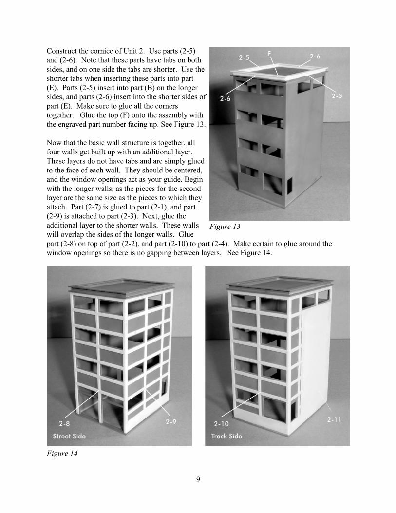
Construct the cornice of Unit 2. Use parts (2-5)and (2-6). Note that these parts have tabs on bothsides, and on one side the tabs are shorter. Use theshorter tabs when inserting these parts into part(E). Parts (2-5) insert into part (B) on the longersides, and parts (2-6) insert into the shorter sides ofpart (E). Make sure to glue all the cornerstogether. Glue the top (F) onto the assembly withthe engraved part number facing up. See Figure 13.
Now that the basic wall structure is together, allfour walls get built up with an additional layer.These layers do not have tabs and are simply gluedto the face of each wall. They should be centered,and the window openings act as your guide. Beginwith the longer walls, as the pieces for the secondlayer are the same size as the pieces to which theyattach. Part (2-7) is glued to part (2-1), and part (2-9) is attached to part (2-3). Next, glue theadditional layer to the shorter walls. These wallswill overlap the sides of the longer walls. Gluepart (2-8) on top of part (2-2), and part (2-10) to part (2-4). Make certain to glue around thewindow openings so there is no gapping between layers. See Figure 14.
Figure 13
Figure 14
10
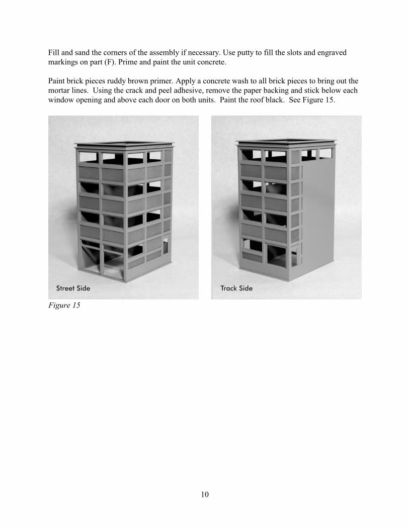
Fill and sand the corners of the assembly if necessary. Use putty to fill the slots and engravedmarkings on part (F). Prime and paint the unit concrete.
Paint brick pieces ruddy brown primer. Apply a concrete wash to all brick pieces to bring out themortar lines. Using the crack and peel adhesive, remove the paper backing and stick below eachwindow opening and above each door on both units. Paint the roof black. See Figure 15.
Figure 15

11
Windows and Doors
Paint part (1-12) silver, all doors (2-13) and garage doors (1-13), (1-14), (2-11), (2-12) gray, allwindow frames black, and all cinder block parts gray. Once dry, install window glazing asdescribed earlier. Apply a black wash to the cinder block to bring out the mortar lines. (See“Window Glass”)
Install all window and doors behind the appropriate openings in both units using super glue(CA). The window frames and cinder block parts will be used in both units. Note that there arefour window frames that are smaller and are only four blocks wide. These are used in Unit 1 onthe “end” wall. There are enough window frames for the entire building should you wish to buildit that way. There are 16 cinder block pieces that may be used to replace the window frames. Now that both units are complete, attach them together using white glue. The units should bejoined so that the street sides are flush. See Figure 16.
Stairs - Unit 1
Create the steps by taking parts (S1-2) though (S1-5) and stack them together with the largest onthe bottom and smallest on top. These parts shouldbe flush on both short sides and one long side.Glue together. Next, insert the tab of one part (S1-6) into the slot in either end of part (S1-1). The rounded corners of part (S1-1) go in the frontof the piece, and part (S1-6) will be flush with theback of part (S1-1). Glue the stair assembly on topof part (S1-1) and between parts (S1-6). Theseparts should be flush with the back of part (S1-1)and (S1-6). Glue one part (S1-7) to each part (S1-6) on the outside of the assembly. These partswill be flush with the back of the assembly. Paint khaki and set aside to dry. See Figure 17.
Figure 16
Figure 17

12
Stairs - Unit 2
Create the steps by taking parts (S2-4)x10 andgluing them together in a staggered fashion. Usethe engraved line on each step as placement fornext piece to be glued on top. On the top of thestack, glue part (S2-3) using the engraved line ofthe part below. Next, take part (S2-1) and put itflat on your work surface with the engraving facingup. Glue part (S2-2) onto part (S2-1). It should beplaced on the left side of the piece, flush with theedge and perpendicular to part (S2-1). Last, gluethe step assembly in place using the engraving asyour guide. (Due to variations in acrylic thickness,the engraved markings for the steps may not be exact.) Paint khaki and set aside to dry. See Figure 18.
(Note: assembly will need to be reversed if you arechanging the orientation of the building)
Track Side Loading Dock
Take part (D1-3)x5 and glue perpendicularly topart (D1-2). Parts (D1-3) should be attached usingthe short side without the notch. Attach to bothends of part (D1-2) and equal distance in between,with all the notches facing the same direction. Glue (D1-1) on top of the assembly. It should beflush on the left side and overhang the front andright side by 1/16". The notches will be on theback bottom of the loading dock. See Figure 19.
(Note: assembly will need to be reversed if you arechanging the orientation of the building)
Truck Loading Dock
Take part (D2-3)x2 and glue perpendicularly toeither end of part (D2-2). The long side without thenotch should be attached to (D2-2). Glue part (D2-1) to the top of the assembly. It should beflush on the back and overhang the other threesides. The notches will be on the back bottom ofthe loading dock. See Figure 20.
Figure 18
Figure 19
Figure 20

13
Entrance Awning
Glue part (A-1) to the top edge of part (A-2) tocreate a lip. Make certain parts are flush. Gluepart (A-3) centered and perpendicular to theassembly. Prime and then paint silver. Paint thelettering. See Figure 21.
Billboard
Take support brackets (B-2)x9 and adhereperpendicularly to the back of the billboard support(B-1). Paint black. Remove letters from the sheetand paint white. Using white glue, attach letters tothe billboard support. It is best to use the sheet theletters were cut from as a template when attachingthem in order to maintain placement and spacing. See Figure 22.
Water Tower, Tanks, etc.
Your kits comes with fours pieces of PVC pipe, 1sheet of parts, plastic coated wire, and styrene tubeso you may construct a water tower and tanks. Youmay choose to construct these items using anyvariation of parts to suit your purposes. The watertower is the only accessory that has a specificconstruction method.
To construct the water tower, take part (T-1) andput it flat on your work surface with the engravingfacing down. Glue part (T-2) on top of (T-1)centered all the way around. Next, glue thesupports (T-3)x8 into the slots of part (T-2). Cut a3/4" length piece of the 1/8" styrene rod and glue itinto the center opening of part (T-2). See Figure 23.
Figure 21
Figure 22
Figure 23

14
Flip assembly over. Using super glue, attach the 1 5/16"W x 1"H piece of PVC pipe centered tothe engraved side of part (T-1). Attach part (T-4) to the top of the PVC pipe using super glue.Last, attach part (T-5) as a cap centered on top of part (T-4). Prime gray and paint supportstructure black. See Figure 24.
The tanks may be constructed vertically or horizontally. Simply take a piece of PVC pipe, glueribs in place if so desired, and then cap the ends. Remember to use super glue when attachinganything to the PVC pipe. Supports may be added if the tank is horizontal. Small caps may beused on top or to cap off styrene rod pieces. Use a pin vise to drill small holes and plastic coatedwire to connect the tanks. See Figure 24.
Signs
Spray the signs with matte spray. Attach the double stick adhesive to the back of the signs, andtrim out using a hobby knife.
Figure 24

15
Final Assembly
Attach stairs, loading docks, signs, and tanks to the building. See below.
Your building is finished and ready to install on your layout. You may add lights and otherdetails. We thank you for purchasing this kit from CMR and hope that you have enjoyed buildingit. Be sure to see our other kits at www.cmrtrain.com.

16
Reverse Orientation Construction
If you wish to reverse the orientation of yourmodel, follow the instructions and figures below.
For Unit 1, swap the “street” and “track” walls. Becertain to install part (1-2) correctly, as it is notsymmetrical horizontally. The part will need to beflipped around so the doors are closer to“common” wall and will open onto the loadingdock correctly. See Figure 25.
For Unit 2, swap the “street” and “track” sidewalls. Note that because three of the wall parts arenot symmetrical, they will need to be flippedhorizontally so that the orientation of the 3 doorson this unit remain in their appropriate orientationwith respect to Unit 1. See Figure 26.
The window frames for asymmetrical walls aredivided into 2 parts, should you choose not to flipthe those walls. This way, the windows will fitwith any wall orientation.
Figure 27 shows the basic building constructed in reverse orientation.
Figure 25
Figure 26
Figure 27


